1
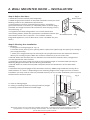
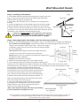
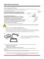
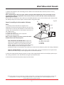
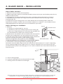
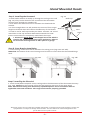
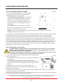
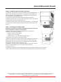
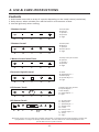
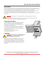
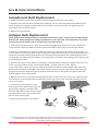
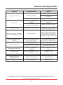
Range Hoods
Owner’s Manual
Pour version française, visitez notre site à l’adresse www.ardaappliances.com
Page 2 - Safety Information
Page 4 - Wall Mount Hoods
Page 8 - Island Mount Hoods
Page 12 - Use & Care instructions
Page 16 - Warranty & Registration
1. IMPORTANT SAFETY INFORMATION
!
Intended for Domestic Kitchen Use Only
* Important: Read the complete manual carefully before installation*
For accuracy, measurements and rough openings should be done based on the actual hood.
Warnings:
TO REDUCE THE RISK OF FIRE, ELECTRICAL SHOCK OR PERSONAL INJURY,
PLEASE OBSERVE THE FOLLOWING:
1. Installation and electrical work must be done by a qualified TECHNICIAN in
accordance with all applicable codes and standards.
2. If the supply cord is damaged, it must be replaced by the manufacturer,
its service agent or a similarly qualified person to avoid a hazard. Any
modifications that may be required to the home’s electrical system for the
installation of the range hood must only be made by qualified electricians.
3. Before servicing or cleaning unit, switch power off at the service panel.
Lock panel to prevent power from being switched on accidentally.
4. Use this unit only in the manner intended by the manufacturer.
5. Sufficient air is needed for combustion and exhausting of gases through the
chimney of fuel burning equipment to prevent back drafting. Follow the
heating equipment manufacturer’s guidelines and safety standards such as
those published by the National Fire Protection Association (NFPA), and the
American Society for Heating, Refrigeration and Air Conditioning Engineers
(ASHRAE), and the local code authorities.
6. When cutting or drilling into wall or ceiling, be careful NOT to Damage
existing electrical wiring and other hidden utilities.
7. Ducted fans must always be vented to the outdoors.
8. To reduce the risk of fire, use only metal ductwork.
9. This unit must be grounded.
We do the utmost to ensure that the provided information is complete and accurate; however, images and
specifications are subject to change without notice. Visit our website at www.ardaappliances.com
for the latest version of this manual.
-2-
Important safety information
!
1.
2.
3.
4.
TO REDUCE THE RISK OF INJURY TO PERSONS IN THE EVENT OF A RANGE
TOP GREASE FIRE, OBSERVE THE FOLLOWING:
SMOTHER FLAMES with a close-fitting lid, cookie sheet or metal tray, and
then turn off the burner. If the flames do not go out immediately, evacuate
and call the fire department.
NEVER PICK UP A FLAMING PAN. – You may be burned.
DO NOT USE WATER, including wet dishcloths or towels – a violent steam
explosion may result.
Use an extinguisher ONLY if:
• You know you have a Class ABC extinguisher and you already know how
to operate it.
• The fire is small and contained in the area where it started.
• The fire department is being called.
• You can fight the fire with your back to an exit.
CAUTION
1. To reduce the risk of fire and to properly exhaust air, be sure to duct air
outside. Do not vent exhaust air into spaces within walls, ceilings or into
attics, crawl spaces or garages.
2. Take care when using cleaning agents or detergents.
3. Avoid using food products that produce flames BENEATH the range hood.
4. The range hood must only be used for the exhausting of cooking fumes in
DOMESTIC kitchens. The manufacturer disclaims all liability for any other
use of the appliance.
5. Two installers are recommended because of the large size and/or weight of
this hood.
6. Only use with 110/120V power plug provided.
7. Please read specification label on product for further information and
requirements.
We do the utmost to ensure that the provided information is complete and accurate; however, images and
specifications are subject to change without notice. Visit our website at www.ardaappliances.com
for the latest version of this manual.
-3-
2. WALL MOUNTED HOOD -- INSTALLATION
Fig. 1
1. Read this manual carefully and completely.
Outlet Cover
2. ARDA range hoods conform to ETL/CSA standards. Check your local
building codes for any additional requirements.
Grounding Pin
3. The appliance has been manufactured as Class I, therefore a
ground connection is necessary. A 110/120V power cord with plug is
provided. The range hood must be installed so that the plug is easily
accessible (Fig. 1).
4. If appliance has been designed for use in both ducted and
recirculating modes, follow the appropriate installation method. (For
Grounded Outlet Plug
recirculation mode a kit is required – not included. Contact
Integrated Appliances, Ltd. to determine if a kit is available for your
hood.)
Step A: Before You Start...
Step B: Planning Your Installation
1. Measure:
a. The floor to ceiling height (A - Fig. 2).
b. Find the centre point of your opening. Mark a plumb line (B) through this point from ceiling to
your range/cook-top.
c. Check your range/cook-top user manual for the specified minimum and maximum distance
above your cooking surface. Mark the minimum clearance (C) on the centre line.
2. Decide where the ductwork will run between the hood and the outside. Short, straight duct
runs will provide the most air flow.
3. Installing a cross brace within the wall at the mounting height is recommended (see Step D Mounting Height Calculation & Cross-Bracing Installation).
4. Decide where to install the 110/120V receptacle within the dimensions of the decorative
chimney.
5. Calculate the required height of the decorative chimney. ARDA range hoods will usually fit on
walls between 7½’ and 8 ½’ depending on the mounting height of the range hood. For a shorter
installation you may need to have the provided chimney cut. For a taller installation you may need
to fabricate an extension piece.
Fig. 2
A - Floor to Ceiling height
B - Ceiling to Cooking Surface (center/plumb line) height
C- Cooking surface to bottom of hood height
A
B
C
We do the utmost to ensure that the provided information is complete and accurate; however, images and
specifications are subject to change without notice. Visit our website at www.ardaappliances.com
for the latest version of this manual.
-4-
Wall Mounted Hoods
Fig. 3
Step C. Installing the Ductwork
1. Arda hoods exhaust vertically up through the ceiling to the roof
(Fig. 3). They can be ducted to the rear behind the decorative
Roof Cap
chimney duct through an outside wall.
2. Plan where the ductwork will run between the hood and the
outside.
3. A short straight duct run will produce the most air flow. Longer
lengths and elbow ducts will reduce the efficiency of the blower.
Wall Cap
4. Install a roof or wall cap outside your home. Connect a 6” round
metal duct to the cap and work backwards towards the hood. Ensure
connections are completely sealed with duct tape.
5. Exhaust air must not be discharged into a flue which is
used for the exhaust fumes from other appliances. Exhaust
air cannot be discharged into an attic space or a garage.
Duct
Hood
!
Step D. Mounting Height Calculation and Cross-Bracing Installation
1. Decide on the mounting height of the hood (C - Fig. 2). You will need to consider the following:
The minimum mounting height. In general the minimum mounting height above an electric
range is 24” and above a gas range is 30”. Check your range’s
Fig. 4
installation manual for the correct minimum mounting height
Framing
for your installation.
Your eye level. Mounting the hood at a height where the
Wood
crosscontrols are at eye level is usually most convenient.
Moun
bracing
ting H
Design. Factors such as symmetry and alignment within your
oles
Drywall
backsplash and/or cabinetry.
The fit of the decorative chimney.
2. Mark the mounting height (C) on the plumb line (B).
Center line
3. The mounting holes on the hood are used for attaching the
hood to the wall. Measure the distance between the bottom of the hood and the top of the
mounting holes on the hood (D - Fig. 5). Draw a line perpendicular to the center/plumb line (B)
at this height. Measure the distance between the
Fig. 5
mounting holes on the hood (E). Center and mark this
Mounting Holes
Offset
measurement on line D. Ensure that this measurement
E
Height
is centered on either side of the center (plumb) line.
D
This is where the mounting holes are to be positioned.
4. Behind the drywall and any backsplash material, install cross-bracing between the wall joists at the level
of the mounting screw holes (Fig. 4)
5. Insert the mounting screws through the marked
mounting holes, leaving about 1/4” of the thread
exposed. Ensure you use the appropriate type of
Center (Plumb)
screws for your wall/crossbracing.
Line
Note: some wall/screw types will require pre-drilling
Mounting Height
B
a pilot hole before inserting the screw.
(to cooktop)
C
We do the utmost to ensure that the provided information is complete and accurate; however, images and
specifications are subject to change without notice. Visit our website at www.ardaappliances.com
for the latest version of this manual.
-5-
Wall Mounted Hoods
Step E. Installing the Electrical
1. Install a 110/120V electric receptacle on the wall within the dimensions of the decorative
chimney (Fig. 6). Note that removal of the plug will void the
Fig.6
warranty of the range hood.
Grounded
Note: All electrical wiring must be done by a qualified
Outlet
person and in accordance with all applicable codes and
Center/plumb
standards. This range hood must be properly grounded.
Line B
Step F. Mounting the Hood
Warning: If unit is being installed above an installed
cooking appliance, ensure the unit is turned off and is
completely cooled before beginning installation.
CAUTION: While installing the hood, take precautions not
to scratch your unit. Remove tool belts, large belt buckles
and any other sharp items while handling the unit. Cover
working surface with a soft blanket.
1. We recommend that two people mount the hood.
!
2. DO NOT REMOVE PLASTIC COATING FROM HOOD UNTIL INSTALLATION IS COMPLETE.
3. Damper installation for HAM52A and HAM52B only:
Inside the hood, under the grease filters, you will find the:
Damper (Fig. 7); Gasket (Fig. 8); Gasket screws (x 4); Wall bracket for the chimney (Fig. 9).
Set the bracket aside for use in Step G. Place the gasket on top of the hood. Place the damper
on top of the gasket. Using the screws provided, affix the damper to the hood.
Fig.9
Fig.7
When unpacking models HAM52A and HAM52B,
please note that the gasket and associated hardware
are packed inside the hood.
Fig.8
4. Before mounting the hood, plug the unit in and test all functions for proper operation:
a. Blower works at all speeds.
b. Lights turn on and off.
c. Damper flaps should open when blower is on.
5. Remove the grease filters from the bottom of the hood to prevent damage during the
installation.
6. With assistance from at least one other person, hold the hood temporarily in position ensuring
the bottom is above the minimum clearance for the cooking surface.
We do the utmost to ensure that the provided information is complete and accurate; however, images and
specifications are subject to change without notice. Visit our website at www.ardaappliances.com
for the latest version of this manual.
-6-
Wall Mounted Hoods
7. Mount the hood on the mounting screws. When the hood has been leveled, secure unit by
tightening screws.
Note: Depending on the hood type, before doing the final tightening of the mounting screws,
the chimney needs to be placed on the hood in order to secure the lips of the chimney when
tightening the screws.
8. Connect a 6” aluminum duct tube (not included) between your hood and duct path. Ensure that
the damper flaps are free to open. Seal all seams using duct tape.
Fig.10
D
Step G. Installing the Decorative Chimney
C
Duct
1. Carefully loosen but do not separate the
telescopic chimney duct pieces (A & B - Fig. 10). The
inside piece is the top and attaches to the wall at the
ceiling. The outside piece is the bottom and rests on
the range hood.
2. Plug in the hood.
3. Install the recirculation kit if required.
4. Attach the wall bracket.
Note: If your ceiling is not even, mount the wall
bracket level at the lowest point.
C
A
B
Arda
A.
vent
cover
A. Upper
Upper vent
cover
For HAM52A & HAM52B only: adjust the
cover
B.B. Lower
Lowervent
vent
cover
width of the support bracket (D) to match the
Screws
C.C. Screws
D. Bracket
upper duct width. Fix it to the wall using the
D. Bracket
screws. Mark a line 4 mm down from the ceiling.
Fix the adaptor to the wall using the screws
provided so that it is centered in line with your hood and at a distance from the ceiling indicated.
FOR ALL OTHER HOODS: on the wall, at the ceiling edge, center the bracket on the plumb line.
Attach to the wall using screws appropriate to the wall material.
5. Place the two nested chimney pieces on top of the range hood. Draw the inside/top piece up to
the ceiling and affix to the wall bracket using the provided screws.
6. Remove the decorative plastic wrap from the hood.
We do the utmost to ensure that the provided information is complete and accurate; however, images and
specifications are subject to change without notice. Visit our website at www.ardaappliances.com
for the latest version of this manual.
-7-
3. ISLAND HOOD -- INSTALLATION
Step A. Before You Start...
1. Read this manual carefully and completely.
2. ARDA range hoods conform to ETL/CSA standards. Please check your local building codes for any
additional requirements.
3. The appliance has been manufactured as Class I, therefore ground connection is necessary.
A 110/120V plug is provided. The range hood must be installed so that that the plug is easily
accessible (Fig. 11).
4.If appliance has been designed for use in both ducted and recirculating modes, follow the
appropriate installation method. (For recirculation mode a kit is required – not included. Contact
Integrated Appliances to determine if a kit is available for your hood.)
Step B. Planning your installation
Fig.11
1. Measure:
Outlet Cover
a. The floor to ceiling height (A - Fig. 12).
b. The distance from your cooking surface to your ceiling. (B)
Grounding Pin
c. Check your range/cooktop user manual for the specified min/
max hood distance (C) above your cooking surface.
2. Decide where the ductwork will run between the hood and the
outside. Short straight duct runs will provide the most air flow.
3. Find the centre point of your range/cooktop. Drop a plumb line
from your ceiling to this point on your cooking surface.
Grounded Outlet Plug
Mark the ceiling where the plumb line starts. Installing
crossbracing between the ceiling joists is required (See Step D).
4. Calculate the required height of the mounting cage and
decorative chimney. ARDA range hoods will usually fit on walls between 8 ½’ and 9 ½’ depending
on the mounting height of the range hood. For a shorter installation you may need to have the
provided chimney and/or mounting cage cut. For a taller installation you may need to fabricate an
extension piece.
Fig.12
A
A - Floor to Ceiling height
B - Ceiling to Cooking Surface (center/plumb line height
C - Cooking surface to bottom of hood height
B
C
We do the utmost to ensure that the provided information is complete and accurate; however, images and
specifications are subject to change without notice. Visit our website at www.ardaappliances.com
for the latest version of this manual.
-8-
Island Mounted Hoods
Step C. Installing the Ductwork
Fig. 13
1. Arda hoods exhaust vertically up through the ceiling to the roof
Roof Cap
(Fig. 13). They can be ducted to the rear behind the decorative
chimney duct through an outside wall.
2. Plan where the ductwork will run between the hood and the
outside.
3. A short straight duct run will produce the most air flow. Longer Wall Cap
lengths and elbow ducts will reduce the efficiency of the blower.
4. Install a roof or wall cap outside your home. Connect a 6” round
metal duct to the cap and work backwards towards the hood.
Ensure connections are completely sealed with duct tape.
5. Exhaust air must not be discharged into a flue which is
used for the exhaust fumes from other appliances. Exhaust
air cannot be discharged into an attic space or a garage.
Duct
Hood
!
Step D. Cross-Bracing Installation
1. In the ceiling, install cross-braces between the ceiling joists (Figs. 14a and 14b).
NOTE that the bottom of the cross-bracing must be level to ensure that the island hood hangs
level.
Fig. 14a
Fig. 14b
Step E. Installing the Electrical
1. Install a 110/120V receptacle on the ceiling within the dimensions of the decorative chimney
(Fig. 14a). NOTE that the removal of the plug will void the warranty of the range hood.
Note: All electrical wiring must be done by a qualified person and in accordance with all
applicable codes and standards. This range hood must be properly grounded.
We do the utmost to ensure that the provided information is complete and accurate; however, images and
specifications are subject to change without notice. Visit our website at www.ardaappliances.com
for the latest version of this manual.
-9-
Island Mounted Hoods
Step F. Mounting Height Calculation
1. For an island hood installation, you will need
to consider the following when calculating the
mounting height (C - Fig. 12 on p.8):
Z
The minimum mounting height. In general the
Telescopic
minimum mounting height above an electric
range is 24” and above a gas range is 30”.
Check your range’s installation manual for the
correct minimum mounting height for your
installation.
Y
Your eye level. On an island hood, mounting
the hood at a height where the controls are at
eye level is usually most convenient.
Design. Factors such as symmetry and alignment within your backsplash or cabinetry.
The fit of the decorative chimney.
Fig.15
X
2. Calculate the available height from the ceiling to the bottom of the hood (X - Fig. 15). Calculate
the height of the hood (Y), then calculate the extended height for the mounting cage (Z).
3. Expand the telescopic cage to the calculated size (Z). Use the screws provided to fix the
telescopic cage in place. If the calculated height of the mounting cage is smaller than the actual
height of the cage, you will need to have both the cage and the decorative chimneys cut to fit
your installation. We recommend that a stainless steel fabricator do this to ensure a straight even
cut. If the calculated height of the mounting cage is larger than the actual height of the cage,
you will need to fabricate an extension piece. Please call our office at 1-800-268-4086 or info@
ardaappliances.com for assistance if required.
Step G. Mounting to the Ceiling
CAUTION: While installing the hood, take precautions not to scratch your unit. Remove
tool belts, large belt buckles and any other sharp items while handling the unit. Cover
lower working surface with a soft blanket.
Warning: If unit is being installed above an installed cooking appliance, ensure the unit is
turned off and is completely cooled before beginning installation.
1. Centre the upper cage on the ceiling around the exhaust duct
Fig.16
opening. Ensure that:
a. The markings coincide with the cross-bracings between the
ceiling joints.
b. The cage is square with the cooking surface below.
c. The side of the cage that has the arrow on it faces the front.
When installed, this is the side of the hood that will have the
controls.
2. Mark the upper screw holes on the ceiling (Fig. 16).
3. Partially screw the four mounting screws provided into the
ceiling at these markings.
4. Ensure that the unit is square and level then completely tighten the screws. The cage should
now be firmly attached to the ceiling.
5. If you have not done so previously, insert the lower cage over the upper cage. Adjust the height
to the necessary distance using screws supplied.
!
We do the utmost to ensure that the provided information is complete and accurate; however, images and
specifications are subject to change without notice. Visit our website at www.ardaappliances.com
for the latest version of this manual.
- 10 -
Island Mounted Hoods
Step H. Installing the Decorative Chimney
1. Attach 6” aluminum duct (not included) to the prepared duct
work in the ceiling. Seal all seams. If using the recirculation kit
(not provided), the air deflector is installed at this step. Please
see instructions provided with kit.
2. Carefully separate the telescopic chimney duct pieces.
3. Attach the inner piece of the decorative chimney to the top of
the cage with screws provided (Fig. 17).
4. Slide the outer piece of the decorative chimney on to the cage
over the inner chimney and temporarily hold in place with two
screws.
Fig.17
Step I. Installing the Range Hood
Note that to avoid injury and/or damage to the hood, this step
of the installation requires three people.
1. Before mounting the hood, plug the unit in and test all
functions for proper operation:
a. Blower works at all speeds.
b. Lights turn on and off.
c. When blower is on, the damper flaps open.
2. Remove grease filters from range hood.
3. With the assistance of two other people lifting the hood from
below, raise the unit until the lower cage sits inside the range
hood lower cage. Be sure the unit is installed with the controls
facing front. Screw hood to cage (Fig. 18).
4. Attach 6” aluminum duct to the hood duct connector. Ensure
that the damper flaps are free to open. Seal all seams.
5. Plug in the unit.
6. Remove temporary screws holding the lower decorative chimney piece in place.
7. Re-install the grease filters and remove protective plastic wrap from the hood.
Fig.18
We do the utmost to ensure that the provided information is complete and accurate; however, images and
specifications are subject to change without notice. Visit our website at www.ardaappliances.com
for the latest version of this manual.
- 11 -
4. USE & CARE INSTRUCTIONS
Controls
1. Arda hoods come with a variey of controls depending on the model choice (see below).
2. Delay timers, when included, turn off the hood in a set amount of time.
3. Use the lights only when cooking.
5 Button Control
A
B
A=Power/Off
B=Speed 1
C= Speed 2
D=Speed 3
E= Light
C
D
E
5 Button Control
A
B
C
D
E
5 Button Control with Timer
B
A
C
A-Delay Timer/15 minutes
B- Speed 1
C= Speed 2
D=Speed 3
E= Light
D
E
Electronic Digital Control
A
B
C
A=Timer
B= Speed Adjust “-”
C=LED Display
D= Speed Adjust “+”
E= Light
D
E
LED Sensor Touch
88
A
B
C
D
E
LED Sensor Touch
:
A
B
C
D
A=Power/Off
B=Speed 1
C= Speed 2
D=Power Burst
E= Light
E1 F
E2
G
H
A=Delay Timer/15 minutes
B= Speed Adjust “-”
C=LED Display
D= Speed Adjust “+”
E= Light
A= Change Filter
B= Delay Timer
C= Speed Adjust “-”
D= Digital Clock
E1= Timer
E2= Delay Timer
F = Speed Adjust “+”
G= Timer
H= Light
We do the utmost to ensure that the provided information is complete and accurate; however, images and
specifications are subject to change without notice. Visit our website at www.ardaappliances.com
for the latest version of this manual.
- 12 -
Use & Care Instructions
Operation
1. For optimum performance in removing cooking odours, it is recommended that you turn
on your range hood prior to cooking and you leave it operating for 15 minutes after cooking.
2. Clean the surfaces of the range hood regularly using a non-abrasive detergent.
3. The grease filters capture the grease particles suspended in the air. They will accumulate
grease and dirt depending on the frequency of the use of your range/cooktop.
4. In order to prevent a fire hazard, it is recommended that you clean the filters at least every
2 months.
!
WARNING: This appliance is not intended for use by young children without
supervision.
There should be adequate ventilation in the room when the range hood is used
simultaneously with other fuel burning appliances.
Cleaning the filter
1. Remove the filters from the range hood and wash
them in a solution of water and liquid detergent,
leaving to soak if necessary. Rinse thoroughly with
warm water and leave to dry.
2. The filters may also be washed in the dishwasher.
3. The aluminum panels may alter in color after
several washes. This is normal and does not alter the
performance of the hood.
4. Replacement filters are available at
www.ardaappliances.com
Underside of Hood
Lighting:
!
WARNING: Do not touch or change light bulbs
while the hood is operating. Wait until the
bulb has cooled before removing.
Depending on your model of ARDA hood, there are two
possible types of lighting: incandescent and halogen.
The hood lights are designed for use during cooking and
not for prolonged general illumination of your kitchen.
Prolonged use of the lights may reduce the life time of
the bulbs.
We do the utmost to ensure that the provided information is complete and accurate; however, images and
specifications are subject to change without notice. Visit our website at www.ardaappliances.com
for the latest version of this manual.
- 13 -
Use & Care Instructions
Incandescent Bulb Replacement
1. Allow the bulb to cool for 10 minutes; remove the grease filter for easy access.
2. Carefully unscrew the bulb to avoid glass breakage. Ensure that the replacement bulb has the
same voltage and wattage specification as the old bulb. Install new bulb in the light fixture by
screwing it into the fixture socket.
3. Replace the grease filter.
Halogen Bulb Replacement
Note: Replacement halogen bulbs are available at hardware stores. Ensure that the replacement
bulb has the same voltage and wattage specification as the old bulb. This information is printed
on the stem of the bulb as well as on the inner ring of the fixture.
1. Disconnect the power source from the hood by unplugging the power cord or turning off the
circuit breaker. Allow the bulb to cool for 10 minutes before removing it from the light fixture.
2. Place a small flathead screwdriver under the outer lip of the fixture (A). With some models it is
also possible to remove the grease filter and press the light fixture out of its mounting bracket from
inside the hood (B). Avoid touching the wires when pressing the fixture out. Holding both ends of
the plug (do not hold wires) press down the locking lever (to unlatch the locking pin) and gently pull
the two sections apart.
3. Remove the cover on the fixture, by placing a small flathead screwdriver between the inner and
outer ring of the fixture in the area marked “OPEN,” and pry loose the inner ring (C).
Using a dry paper towel, pull out the old bulb and discard. Hold the new halogen bulb with a dry
paper towel between your fingers. The paper towel prevents oils from your skin from adhering to
the glass of the bulb. Align the pins of the bulb with the holes in the fixture and gently push the
bulb straight in until fully inserted.
4. Replace the cover on the fixture by aligning the three slots on the cover with the matching slots
on the fixture and pressing firmly on the outer metal ring of the cover. To avoid breakage, do not
press on the glass.
5. To reconnect the plug line up the
ends (square hole with square peg) and
gently press together until they lock.
Snap the light fixture back into its socket
by pressing the outer ring of the fixture.
Do not press on the glass.
B
A
6. Reconnect the power to the hood.
C
We do the utmost to ensure that the provided information is complete and accurate; however, images and
specifications are subject to change without notice. Visit our website at www.ardaappliances.com
for the latest version of this manual.
- 14 -
Trouble-Shooting Guide
Problem
Possible Reason
Solution
Ensure the plug is connected
Hood doesn’t turn on
Poor airflow
No electrical supply
Ensure the main switch is
turned on
Power cord is damaged
Call ARDA service
Aluminum grease filters
clogged
Clean the filters and replace
when dry
Charcoal filters clogged
(recirculating mode only)
Replace the charcoal filters
Hood is not secured in place
Check the installation of hood
Tighten mounting screws
Motor running but no airflow,
or air comes back into room
Damper blocked
Check outside cap to ensure
that it is clear. Check damper
opens when unit is turned
on. Call installer to check for
blockages or narrowing of the
duct.
Motor stops after a few
minutes
The hood is installed too near
the cooking surface
The hood must be at least
61cm (24” ) from the stove
Fan speed too low
Use one of the higher settings
Charcoal filters not installed
In recirculating mode, charcoal
filters must be installed
Oil dripping onto stove
Aluminum grease filter
saturated
Wash the aluminum grease
filters
Whirring sound
Something in contact with fan
blade
Call ARDA service
Hood is vibrating
Strong cooking smell
Fan does not work
Call ARDA service
Lights do not work,
but fan does
Bulbs have burnt out
Replace bulbs
All hood lights go out at once
Transformer blown
Call ARDA service
We do the utmost to ensure that the provided information is complete and accurate; however, images and
specifications are subject to change without notice. Visit our website at www.ardaappliances.com
for the latest version of this manual.
- 15 -
5. LIMITED WARRANTY
This warranty applies only to the original purchaser and may not be transferred. This warranty is
applicable within North America only, to hoods installed for normal, non-commercial use in PRIVATE
SINGLE FAMILY HOUSEHOLDS.
Arda Appliances North America (hereafter “Arda”) warrants its products to be free from defects in
materials or workmanship for a period of ONE YEAR from the date of original purchase. It further
warrants the motor (part only) for an additional ONE YEAR. During the warranty period,
Arda will, at its option, repair or replace, without charges, any product or part which is found to be
defective under normal use and service. This warranty covers parts and labor at approved company
rates, of $95 per hour, up to a maximum of one (1) hour. Proof of payment to service repair
company is required.
THERE ARE NO OTHER WARRANTIES, EXPRESS OR IMPLIED, INCLUDING BUT NOT LIMITED TO,
IMPLIED WARRANTIES OR MERCHANT ABILITY OR FITNESS FOR A PARTICULAR PURPOSE. Proof of
purchase/original invoice and serial number is required for warranty claims. Keep a photocopy
easily accessible.
This warranty will be void if the serial plate has been removed or disfigured.
EXCLUSIONS - This Arda limited warranty will not cover:
• Aluminum filters, lights or glass canopies, blower wheel damage
• Regular maintenance and service (except by an authorized Arda repair centre)
• Damage resulting from accident, alteration, misuse, abuse, fire, flood, acts of God, improper
installation, installation not in accordance with electrical codes, or use of consumables or cleaning
products not approved by Arda
• Repair of an appliance used in other than normal, single-family household, or in a manner that is
contrary to operation and/or installation instructions
• Cosmetic damage or freight damage caused by 3rd party freight company
• Service to product that is not easily accessible due to unusual, exceptional, or difficult installation
that requires removal of fixtures, other than the Arda product, for repair
• Service calls to instruct you how to use the appliance (i.e. user product education)
• Expenses for travel and transportation if your appliance is located in a remote area where service
by an authorized Arda servicer is not available
The cost of repair or replacement under these exclusions shall be borne by the customer and
agreed to before a servicer is dispatched.
ARDA SHALL NOT BE LIABLE FOR INCIDENTAL, CONSEQUENTIAL OR SPECIAL DAMAGES ARISING OUT
OF OR IN CONNECTION WITH PRODUCT USE OR PERFORMANCE.
For an ARDA authorized repair centre please contact Arda at:
1-800-387-3924 (U.S.), 1-800-268-4086 (CAN), or [email protected].
We do the utmost to ensure that the provided information is complete and accurate; however, images and
specifications are subject to change without notice. Visit our website at www.ardaappliances.com
for the latest version of this manual.
- 16 -
Place photocopy of proof of purchase
here
We do the utmost to ensure that the provided information is complete and accurate; however, images and
specifications are subject to change without notice. Visit our website at www.ardaappliances.com
for the latest version of this manual.
- 17 -
Distributed by Arda Appliances NA.
501 Oakdale Road, Toronto, Ontario M3N 1W7
Tel: 416-646-2500 Fax: 416-646-2505
1-800-387-3924 or 1-800-268-4086
www.ardaappliances.com
HM-20140820