1
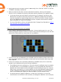
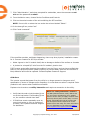
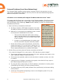
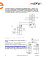
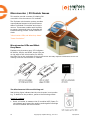
Reference Manual Troubleshooting an Enphase Microinverter System Contents Enlighten Messages and Alerts 4 ACFOOR (AC Frequency Out of Range) 4 ACVOOR (AC Voltage Out of Range) 5 Critical Temperature DC Too Low 8 DC Too High 8 7 Envoy/EMU not Reporting 9 Gateway Failure 9 GFDI / GFI trip 9 Grid Gone 10 Module Failed to Report 11 Over Temperature 11 Zigbee Device Failed to Report 11 Zigbee USB Stick Removed 11 ENVOY and Communications Issues General Envoy Issues 12 12 A physical Ethernet connection is not practical at this site LCD is completely blank 12 12 LCD displays “Reset Clock”12 LCD displays “Envoy Failure” 12 Internet Problems (Local Area Networking) 13 LCD shows a non-routable/self-assigned IP address and also shows “-Web” 13 LCD periodically shows “-Web” for minutes or hours at a time.14 LCD shows a good IP, but also shows “-Web” 15 The DSL modem at the site has only one Ethernet port, and it is being used 15 The Envoy cannot get a “+Web” even though all premises networking is intact 15 Internet service is not available on site 15 Can I use a dial up Internet connection with the Envoy? 16 Are My Power Line Communication Bridges Working? 16 The Envoy is using a static IP and cannot get a web connection 17 Communication Issues between Envoy & Microinverters (Power Line Communication)17 Inverters are not detected / Power line communication level is low/poor 18 How to identify an interfering load 20 This is a Line-side Tap (or Supply-Side, or PLC) Installation When do I need an additional Envoy? 21 22 How to get further training on Enphase power line communication Microinverter / PV Module Issues 23 Microinverter LEDs and What they Mean 23 The Microinverter LEDs are blinking red 22 23 The Microinverter LEDs are blinking orange 24 The Microinverter LEDs are not lit 24 Power Production 25 The unit under review shows low production. 25 Why is one unit showing 0W production when adjacent units are productive? My panels are dark in Enlighten and no production value is displayed Enlighten will not allow me to select the panel 28 I would like to see my panel’s production history 28 Run a report to view production history 28 Use the Graph widget to view production history 29 There is an event or alert message on the system 29 28 25 Troubleshooting An Enphase Installation This document describes trouble-shooting flows and procedures only. For product and installation information, refer to http://www.enphase.com/support/downloads. Troubleshooting areas covered in this document include: Enlighten Messages and Alerts ENVOY and Communications Issues Microinverter / PV Module Issues Enlighten Messages and Alerts The following event messages may appear in Enlighten or in the Envoy interface. If you have received an Enlighten alert in email, read the email through. It includes information on whether or not action is required and what that action should be. ACFOOR (AC Frequency Out of Range) The inverter reports that the frequency coming from the utility is either too low or too high as specified by UL standards (UL1741). The nominal frequency range for M190, M210 and D380 microinverters is 59.3 to 60.5; typical is 60.0. Frequency out of range events are usually transient and indicate an anomaly from the utility; usually this is self-correcting by the utility. If the condition persists, troubleshoot as follows. These events can happen because of an actual frequency outof-spec condition, but more likely, they trip because of either a poorly shaped AC waveform or excessive THD (Total Harmonic Distortion) emanating from the utility service. This type of error rarely affects just one unit, and is usually indicative of an AC service issue. Along with ACFOOR events, Grid Gone events may also be occurring. This is an indication of Anti-Islanding, which sometimes goes hand-in-hand with ACVOOR (AC Voltage Out of Range) and ACFOOR. 4 Copyright © Enphase Energy, Inc. 2011 What does “AntiIslanding” mean? “Anti-islanding” is protection against the continuous operation of the inverter and part of the utility load while isolated from the remainder of the electric utility system. This means that if power from the utility is disconnected, the utility-interactive inverter will stop exporting power within two seconds. This is to protect utility line workers and loads. 06/15/2011 ACVOOR (AC Voltage Out of Range) The inverter reports that the AC voltage coming from the utility is either too low or too high as specified by UL standards (UL1741). Acceptable ranges for AC service are shown in the table below: 240 Volt AC Split Phase 208 Volt AC Three Phase L1 to L2 211 to 264 Vac L1 to L2 to L3 183 to 229 Vac L1, L2 to neutral 106 to 132 Vac L1, L2, L3 to neutral 106 to 132 Vac This condition should correct itself, as there are often periodic variations in Utility voltage. If the condition persists, troubleshoot as follows. When an entire branch or multiple branches are impacted Things to check: 1. Measure voltages for L-L and L-N for all phase-conductors at the service entrance (PCC), at each Enphase branch circuit breaker, at each Enphase branch circuit junction box, at each Enphase branch circuit AC pigtail (if used in this installation), and at the last microinverter of each Enphase branch circuit. 2. Verify that the AC pigtail or cabling to the junction box is correctly terminated per wire color. (See the installation manual for the microinverter being used.) 3. Verify that the correct circuit breaker has been used. (Is the amperage rating correct? Are the number of termination poles correct?) • If the breaker is undersized, the branch may experience nuisance tripping at peak production times. • If the breaker is oversized, the branch may have been damaged with too much current flow through the microinverters. 5 Copyright © Enphase Energy, Inc. 2011 06/15/2011 4. Verify that the service entrance power is not coming from a 240 Vac “DELTA” or 240 Vac “STINGER” secondary transformer. 5. Make sure that the site does not have undersized conductors, either to the Enphase branch circuit or between the primary load center and the subpanel (if a subpanel exists). • In the case where the array branch circuits land on a PV subpanel, and there is additional wire run back to the main service tie-in, additional voltage drop calculations must be completed. A typical voltage drop limit is 3% for AC branch circuits; however, this is not adequate for utility-interactive inverters. Enphase recommends a voltage drop of less than 1.5 volts or 0.6 percent. • For more information, refer to our Application Note “Voltage Drop Calculations: http:// www.enphase.com/support/downloads. When only a few microinverters are impacted 1. If the condition alternates among microinverters, incorrect cabling may be in use. The following Enlighten snapshot shows the result of using 208 Volt cabling at a site with 240 Volt service. Notice that only every third unit is productive. 2. If there is only one unit affected by the ACVOOR, and the condition persists with consistent, out of spec readings, the problem is likely with the microinverter, and it may need to be replaced. 3. If there are multiple units consistently affected by ACVOOR events, this is most likely caused by an installation/wiring error during installation. • If the affected units are contiguous or if an entire branch is affected, there is probably an On/Off switch, or a homemade AC combiner, or an incompatible AC disconnect inbetween the circuit breaker and the AC pigtail of the PCU branch circuit. Or, it may be faulty wiring, terminations, or circuit breakers only for those affected Enphase branch circuits. Sometimes something as simple as a wire terminated on a circuit breaker that is not screwed down tightly will cause ACVOOR on a given branch circuit. • It may be that an AC pigtail is defective, or that it’s AC connector (or one of the microinverters on the branch’s AC connector) is damaged or defective. If, for example, 6 Copyright © Enphase Energy, Inc. 2011 06/15/2011 on a branch circuit the first three units are fine, but the remaining 8 or 9 units on the branch are in a state of ACVOOR, there is something wrong either at location #3 or #4 in the branch circuit, affecting the AC Voltage from that point and on downstream into the branch circuit. • If the ACVOOR is not an installation or wiring defect, and there are multiple units impacted on an intermittent basis, it may be that the site’s utility service is simply high. One of the following may be causing this on the utility side: - The utility transformer bringing service to the site is damaged or defective. - The utility is purposely pushing the higher AC voltage into some areas during times of peak demand. - The homerun conductors from the Enphase branch circuits to their respective circuit breakers are undersized. For more information, refer to the Application Note on Voltage Drop Calculations: http://www.enphase.com/downloads - Is the site using a step-up transformer in-between the primary load-center and the Enphase branch circuits? If so, this can create ACVOOR conditions. • If all of the above have been checked and verified, and ACVOOR nuisance tripping is still occurring, and neither the installer nor the utility can mitigate, Enphase can upgrade all of the microinverters to a parameter table which allows for slightly expanded trip-points, while still remaining within spec. Critical Temperature This rare condition occurs if the inverter reports an internal temperature that exceeds it rated range. It reacts by producing less power to reduce internal temperature. Once the internal temperature of the inverter diminishes, the microinverter resumes full power production and the error message will clear. No action is required unless the condition persists. If it persists, contact Enphase Energy customer support. This reflects internal temperature coming from a sensor inside the microinverter, not the ambient temperature. For more information, see the Enphase Technical Brief on temperature: http://www.enphase.com/downloads 7 Copyright © Enphase Energy, Inc. 2011 06/15/2011 DC Too Low The inverter reports that DC input voltage from the PV module is too low. This is a normal condition that occurs in the morning and in the evening, but during the day may results from any of the following conditions: • This message can appear during extended periods of low solar irradiance (for example, a period that includes the night hours plus a few hours of low sunlight after sunrise). • This event may indicate a bad or missing DC connection to the inverter. If this condition occurs during daylight hours, we recommend that a qualified electrician inspect the DC connection between the module and the inverter. The connection may need to be tightened or may be experiencing wear and tear and require replacement. • If the microinverter is having DC Too Low events during daylight hours, it may have been paired with an incompatible PV module. Is the PV module on the Enphase Compatibility list? If the PV module is not compatible it may work sometimes, but will not work consistently or effectively. Some incompatible PV modules will not produce enough DC to start up the microinverter. To check DC input measurements to a microinverter, see “Check DC measurements” in this document. • Is it producing at all, or does it show zero production? If it shows zero production, does the site use adaptors (or jumpers) between the PV module and the microinverter? It may be that polarity is reversed. Verify by measuring the PV modules VOC (Open Circuit Voltage) and inspect the positive and negative markings on the PV module and microinverter. • To determine if the problem is with the microinverter or with the PV module, it may be necessary to swap the DC leads from the suspect unit and an adjacent unit. If after checking Enlighten periodically (this may take up to 30 minutes), the problem moves to the adjacent module, this indicates that the PV module isn’t functioning correctly. If it stays in place, the problem is with the microinverter. Call Enphase Customer for help in reading most current microinverter data and for help in obtaining a replacement microinverter, if needed. Never rule out the possibility of a damaged or defective PV module. They are somewhat fragile, directly exposed to the elements, and have a very long service-life expectation. The glass on the surface of the PV module can become cracked, lowering the PV module’s output or causing it to trip a “Ground Fault” (GFI). DC Too High The inverter reports that DC input voltage from the PV module is too high. • If the microinverter is having DC Too High events, it may have been paired with an incompatible PV module. It may be that the PV module generates a higher voltage than is recommended for the inverter. Check that the PV module and inverter are compatible by referring to the Module Compatibility List: http://www.enphase.com/support/downloads. • If the DC Too High is being reported across multiple units, and incompatible PV modules have been ruled-out, contact Enphase customer support to verify the firmware version running on the microinverters. 8 Copyright © Enphase Energy, Inc. 2011 06/15/2011 Envoy/EMU not Reporting The broadband Internet connection that the Enphase Envoy uses to communicate to the Enlighten servers is experiencing a problem. If the Envoy displays a status of –Web in the LCD window, it is not currently communicating with the Enlighten servers. The Internet service may be down or the router may be unplugged or turned off. Internet connections often have temporary outages. If the situation persists, contact your ISP (Internet Service Provider). When the connection is restored, the Enphase Envoy communication gateway will catch up with the transmission of all energy data it has stored. • It could be that Internet service is dropping out periodically. Call your ISP if you notice that other devices at the site are also losing Internet connectivity. • Do you have dial up Internet service? Dial up internet service is not supported on the Envoy. • The Envoy may have an internal error, see “General Envoy Issues”. • See “2. Did the Envoy previously have an Internet connection at this site?” Gateway Failure The Envoy has detected a software problem. To clear this message: Unplug the Envoy from the electrical outlet and then plug it back in. Do this only once. If it returns to failure mode, contact Enphase Customer Support. GFDI / GFI trip A microinverter has detected ground fault current greater than one amp on the DC side. You can attempt to clear this condition through the Envoy Interface by sending the ClearGFI message to the affected microinverter. If the Envoy is on a Local Area Network, you can access it from another computer which is also on that same LAN (start with step 4 below). If the Envoy is not on a LAN, then you can directly connect an Ethernet cable between the Envoy and your laptop by performing all of the following steps: 1. Connect one end of the Ethernet cable supplied with the Envoy to the Ethernet port on the Envoy (or browse to it on your Local Area Network). 2. Connect the other end of the Ethernet cable to the RJ45 network port of the computer. 3. Open the Internet browser application on the computer. 4. In the browser address window, enter the IP address displayed in the Envoy’s LCD window (e.g., 192.168.1.101). 5. If you fail to make a connection at this point, you can manually configure your subnet to 169.254.120.2 and subnet mask to 255.255.0.0. 6. Once the browser has successfully connected with the Envoy, the home screen is displayed in the browser window. 9 Copyright © Enphase Energy, Inc. 2011 06/15/2011 7. Click “Administration”, and when prompted for credentials, enter the username as admin and the password as admin. 8. From the Admin menu, choose Device Conditions and Controls. 9. Click on the serial number of the unit exhibiting the GFI condition. NOTE: Do not click or select the box under the column labeled “Select”. 10.In the clear-gfi box, select “set”. 11.Click “send command”. If the condition persists, and keeps happening, there may be a physical, installation reason for it. Common reasons for GFI trips include: • Water ingress in the PV module itself, due to damage or defect of the surface or its seals • A pinched or crimped D/C wire from the PV module’s junction box. If GFI events persist after clearing the condition from the Envoy, and you have verified that there is not a physical problem (water-ingress or a pinched lead), then the microinverter is likely defective and must be replaced. Contact Enphase Customer Support. Grid Gone The inverter reports that power from the utility is no longer present or has gone out of specification in terms of voltage and/or frequency. In most cases no action is required. Solar production will resume when conditions normalize. Enphase microinverters are utility interactive and require a connection to the utility. What is a “Utility Interactive” inverter? • Verify that the solar circuit breaker(s) are on at the load center. If all breaker(s) are on, the condition should clear itself. • If Grid Gone events repeatedly occur on one microinverter or only on portions of a branch, call Enphase Customer Support for assistance. 10 The NEC (National Electric Code) defines this as, “An inverter intended for use in parallel with an electric utility to supply common loads that may deliver power to the utility.” In other words, it describes the type of inverter that lets PV system owners export their excess power back to the utility. For more information, see our whitepaper on the subject at http:// www.enphase.com/support/downloads. Copyright © Enphase Energy, Inc. 2011 06/15/2011 Module Failed to Report The microinverter reporting this condition is unable to communicate with the Envoy over the AC power lines. Occasional instances of this error may be ignored. Inverter communications will likely recover on the next reporting cycle. • If communications do not recover right away (the Envoy polls the microinverters every five minutes), make sure that the Envoy is plugged in very near to your circuit breaker panel. Also, if other devices are sharing the electrical outlet with the Envoy, remove those devices to improve communication signal strength. • If the Enphase Envoy was recently relocated or if new devices or appliances were added to the circuit, it is possible that the new situation is not suitable for power line communications. You may need to relocate the Envoy to improve signal strength and reduce interfering noise on the power lines. • If several inverters are reporting this condition, you may need to relocate the Enphase Envoy to another electrical outlet to improve communication signal strength. For further troubleshooting steps, see “Inverters are not detected / Power line communication level is low/poor”. Over Temperature See “Critical Temperature”. Zigbee Device Failed to Report If the Envoy is connected to an Environ thermostat, this condition may occur if there is an interruption in communication between the Environ thermostat and the Envoy. Make sure the Envoy ZigBee USB stick is plugged into the Envoy. Occasional instances of this error may be ignored, as a temporary interference to the radio signal may cause this condition and will recover on its own. If this condition persists, it may be necessary to add a ZigBee repeater to boost signal strength between ZigBee devices. See the Environ Smart Thermostat Installation and Operation Manual at http://www.enphase.com/support/downloads for more information. Zigbee USB Stick Removed The Envoy Communication Gateway no longer detects the presence of the ZigBee USB stick. Make sure that the ZigBee USB stick is fully seated in the Envoy USB port. See the Environ Smart Thermostat Installation and Operation Manual at http://www.enphase.com/support/downloads for more information. 11 Copyright © Enphase Energy, Inc. 2011 06/15/2011 ENVOY and Communications Issues The following sections describe possible problems and solutions. Areas covered include: “General Envoy Issues” “Internet Problems (Local Area Networking)” “Communication Issues between Envoy & Microinverters (Power Line Communication)” General Envoy Issues A physical Ethernet connection is not practical at this site You’ve found a location for the Envoy that yields a good signal-strength between the Envoy and the Microinverters (over the power lines), but it is remote from the router. An Ethernet cable from the broadband router to this spot is not practical. • Use the power line communication bridges that came with the Envoy as shown. • Or, you can use a wireless Ethernet bridge. (available at computer stores.) LCD is completely blank 1. Try another outlet (just in case). 2. If this fails, the unit must be replaced. There are no field replaceable parts for the Envoy. The whole unit will be replaced. LCD displays “Reset Clock” If the Envoy has a current Internet connection, let it use this connection to retrieve an upgrade from Enphase. This may take up to 90 minutes, depending upon the speed of the connection. You may need to call Enphase Customer Support to initiate the upgrade. LCD displays “Envoy Failure” This message displays after the Envoy has tried unsuccessfully three times to initialize. This may happen when the Envoy has been moved, and its initialization process interrupted. 1. Unplug the Envoy from the electrical outlet and plug it in once again. Leave it in place for at least 15 minutes. 2. If it continues to display Envoy Failure or if it never moves beyond the Initialization stage, call Enphase Customer Support. 12 Copyright © Enphase Energy, Inc. 2011 06/15/2011 Internet Problems (Local Area Networking) The Enphase ENVOY operates just as another computer would in the premises. As such, many of the troubleshooting steps for the Envoy are the same as troubleshooting steps for additional computers in the house. LCD shows a non-routable/self-assigned IP address and also shows “-Web” This means that the Envoy has no connection to the Enlighten website. If the Envoy shows a self-assigned IP (169.254.120.1) and “-Web”, either a physical Ethernet connectivity issue is preventing it from obtaining a DHCP-issued IP address, or there is a setup problem. Troubleshoot as follows. 1. How is the Envoy connected to the Router? a. The Envoy requires a CAT5 cable connection to a router. The USB port cannot be used for an Ethernet connection. b. Make sure it is connected to a broadband router. A switch or hub cannot be substituted for the router. i. Find out what make and model router is being used. Do a web search for the equipment (this will help you discover if it is a true router, rather than a hub or switch). ii. A switch or hub placed between the modem and the ISP connection may also cause this problem. c. On the rear of Envoy next to the LAN port, is the Envoy network port light lit? If so, the Envoy is waiting for a response from Enlighten, and will likely show “+Web” soon. If not, reseat connections or try another CAT5 cable. What is DHCP? The Envoy requests an IP address from the broadband router during the power-up sequence. The router obtains the IP address from a Dynamic Host Configuration Protocol (DHCP) server. IP Addresses are assigned from a pool of available IP addresses and ‘leased’ to each device in the Local Area Network (LAN). The Envoy, like other computers in the LAN, uses the DHCP IP address as its path to the Internet. 2. Did the Envoy previously have an Internet connection at this site? If so, what has changed? Is it a new router or ISP? Was there a power outage? a. If yes to any of these, power cycle all units in the chain, applying power again in this order: Cable/DSL Modem, Router, and Envoy. b. If the router was replaced, make sure the new device is actually a router, not a hub or a switch. c. Lookup the site in Enlighten. According to the graph, when did this Envoy report in last? What changed at that point in time? d. Try using the Envoy menu button to “Get IP address.” (Procedure for invoking menucommands can be found in the Envoy product manual) e. Try another Ethernet (CAT5) cable (between Envoy and Router) to eliminate cabling as the problem. f. Is there an “Envoy/EMU not Reporting” event on the Enlighten system? If so, see “Envoy/EMU not Reporting”. 13 Copyright © Enphase Energy, Inc. 2011 06/15/2011 3. If power line communication bridges (from Enphase) are being used, check that all three LEDs are either on or blinking as described in “Are My Power Line Communication Bridges Working?” a. Relocate one of the bridges to a different power outlet, and make sure that neither one is in a power-strip or UPS battery-backup device. b. Bypass the bridges and plug the Envoy directly into the Router to eliminate the bridges as the source of trouble. They may be faulty or too far apart. c. Replace the Ethernet cables, one at a time, to eliminate these as the cause. 4. Is there a firewall set up on the Local Area Network (LAN)? Most routers either have the firewall disabled or they come with a basic firewall rule of “Allow all outbound traffic but disallow all inbound traffic”. This allows you to view any website, but prevents unsolicited Internet traffic from coming into the premises via the router. If firewalling is active on the router at the site, enable the following rules: Direction Source Protocol Port Destination What is a Firewall? A network firewall is a mechanism used to allow or disallow certain types of inbound or outbound traffic to your LAN. Firewall rules are specific rules that you can set up to allow or disallow different types of network traffic. OUT <Envoy IP address> TCP 443 reports.enphaseenergy.com OUT <Envoy IP address> TCP 443 home.enphaseenergy.com OUT <Envoy IP address> TCP 123 us.pool.ntp.org 5. Is the premises router setup with MAC (media access control) filtering? This prevents the Envoy from obtaining a DHCP address. What is a MAC Address? If the broadband router has MAC Filtering enabled, the router refuses the DHCP A MAC address is a unique identifier permarequest. nently assigned to a network interface. MAC • Temporarily disable MAC filtering and then add the MAC address of the Envoy to eliminate this as the problem. LCD periodically shows “-Web” for minutes or hours at a time. filtering is a common security technique, where you can enter a list of MAC addresses from the other computers at your site that share the router. As a result, only those MAC addresses can participate in the router’s network. In other words, MAC filtering prevents outside MAC addresses from using the router. If the Envoy LCD intermittently shows a good IP and “+Web”, but periodically shows “-Web” for minutes or hours at a time. • It could be that Internet service is dropping out periodically. Call your ISP. • Does the Envoy connection drop when another device at the premises obtains an Internet connection? A switching device at the premises is likely allowing only one Internet 14 Copyright © Enphase Energy, Inc. 2011 06/15/2011 connection at a time. LCD shows a good IP, but also shows “-Web” This means that the Envoy has no connection to the Enlighten website. The LCD shows a good IP (something other than 169.254.120.1), but also shows “-Web”. • The Envoy is waiting for a response from Enlighten, and will likely show “+Web” soon. Wait a few minutes longer. What is a WAN, and what is a LAN? WAN = Wide Area Network (the network beyond your local premises) LAN = Local Area Network (the network within your local premises) • Check that the Envoy is connected to a broadband router and not a hub or switch. The DSL modem at the site has only one Ethernet port, and it is being used If the site has only a single-port DSL modem and the system owner’s one computer is already taking up that one port, you will need to install a broadband router to allow multiple private LAN connections to the single WAN connection. Also, if their broadband connection is setup to only allow one Internet-connected host at a time, contact the ISP to change the account to allow multiple hosts to connect at one time. The ISP may recommend a router, or you may opt to buy one at a retailer. The Envoy cannot get a “+Web” even though all premises networking is intact If you have gone through all appropriate troubleshooting exercises and cannot get the Envoy to show a “+Web” condition and other computers in the LAN are able to get to the Internet, then it may be that the Envoy has a hardware or networking problem. Call Enphase Customer Support. Internet service is not available on site Consider buying an air card. There are some cases where this is the only Internet connectivity option for the site. Air cards are also called EVDO or CDMA cards and typically provided by Sprint, Verizon or AT&T. There are two ways to use an air card: 15 Copyright © Enphase Energy, Inc. 2011 06/15/2011 • Purchase an air card compatible router (e.g., Cradlepoint MBR 900 or MBR 1000). Plug the air card in to the indicated port on the router to create a LAN at the site. • With the air card plugged into a laptop computer, configure the laptop for “Internet Connection Sharing”. Plug the Envoy’s Ethernet/Network cable into the RJ‐45 port of the laptop, and then configure the laptop to “bridge” the communications between the ENVOY and the wireless‐broadband card. Be aware that this configuration can be complex and possibly inconsistent. Also note that this works best if the computer is running the Microsoft Windows XP operating system. Windows XP offers a feature named “Internet Connection Sharing”, or ICS, to act as a “proxy” between a 2nd network computer (in this case, the ENVOY) and an alternate, broadband Internet connection (the Sprint/ Verizon/AT&T card). Consult Microsoft’s article on this for how to configure Windows XP to allow this: http://support.microsoft.com/kb/306126. For other operating systems, please browse the web for “Internet connection sharing” and your operating system name. After installing the air card, you can then install the Envoy as described in the Envoy Installation and Operation Manual at http://www.enphase.com/support/downloads. Can I use a dial up Internet connection with the Envoy? Dial-up Internet connections do not allow consistent communication between the Envoy and Enphase. As such, Enphase Energy does not recommend or support dial‐up connections. Are My Power Line Communication Bridges Working? Use the status lights to verify connections. The table below describes the lights on the front panel of the unit. Indicator State What it means Power On Off Indicates device powered on Indicates no power PLC Activity Blinking Off Indicates activity on power line Indicates no activity on power line (should blink intermittently) Ethernet Link On Blinking Off Indicates Ethernet connectivity Indicates Ethernet traffic Indicates no Ethernet activity 16 Copyright © Enphase Energy, Inc. 2011 06/15/2011 The Envoy is using a static IP and cannot get a web connection If the site owner prefers not to use DHCP, the Envoy must be set up to use a static IP address. • Use the Envoy’s web-interface to navigate to the ADMINISTRATION page. The Username is “admin”, and password is “admin”. Click the “Network Connectivity” menu item. This allows you to see if the Envoy is using DHCP or Static-IP, and allows you to change this setting if needed. • Click “Check Network Connectivity” to view the Envoy connections. For more information on how to use the Envoy Interface, refer to the Envoy Installation and Operation Manual at http://www.enphase.com/support/downloads. Communication Issues between Envoy & Microinverters (Power Line Communication) Built into each Enphase microinverter is a sophisticated protocol that uses the power lines at the site for communication with the Envoy. Every load in the house or business (televisions, lights, dishwasher, outlets, light switches, etc.) shares this common collection of power lines and circuits, all of which terminate at the load center. The load center is where all of the circuit breakers are located. It is typically found on the side of the house or building or in the garage. Since the power lines used for communication are shared with other loads, interference can occur to communication, particularly as new devices are plugged in. Power line communication between the Envoy and the microinverters is completely separate from the Envoy Internet communication. That is what makes the Envoy a “gateway device”. One side of the Envoy communicates with the microinverters via the power lines. The other side of the Envoy communicates with the Internet using a standard Ethernet/network cable plugged into your broadband router. 17 Copyright © Enphase Energy, Inc. 2011 06/15/2011 At power-up, the Envoy performs a power line communication check to determine the strength of the signal between the microinverters and the Envoy. This check does not check Internet communications. During this time, the Envoy LCD window shows that a Communication Check is being done. A few minutes after power up, the Envoy displays a number of bars, from 0 to 5 (similar to a cell-phone’s signal strength indicator), indicating the signal strength of the power line communications between the Envoy and the microinverters. • A level from 3-5 is usually sufficient. • A number of 1-2 is workable, but not ideal. In these cases, the Envoy should be relocated to a dedicated outlet closer to the load center. • Zero bars means that either the Envoy needs to be relocated, or there are one or more devices causing interference between the Envoy and its microinverters. It may also mean that the Envoy has never detected any devices, and a device scan should be initiated. Inverters are not detected / Power line communication level is low/poor The Envoy LCD level indicator shows a level of 2 or below, or you may be seeing “Module Failed to Report” events. 1. It may be that the Envoy is plugged into an AC outlet that is too far from the electrical load center. Try relocating it to an outlet physically closer to the load center. 2. Is there an unbroken Neutral line from the load center to the solar array branch circuit? This is required for system communications. 3. Is another device causing interference? • If the ENVOY is not detecting the Microinverters in the array(s), or if the event‐log is frequently lists “Module Failed to Report” events, then either the power line communication signal strength is weaker than required, or there is interference on the line from a device at the site. • In some instances, we’ve seen these devices interfere with power line communications: power strips and surge protectors on the same circuit UPS (Uninterruptible Power Supply) / battery backup units on the same circuit dimmer switches home automation/security devices that use power line communication touch lamps battery chargers (cell phone and laptop chargers) AC adapters (laptop power cord) heavy rotating motors (e.g., fans, refrigerators, freezers, water pumps) workshop equipment (e.g., drill press, table saw, wood routers, planers) CFLs (Compact florescent lights) with failed ballasts, anywhere in the home electronic pest deterrents GFI outlets some brands of arc-fault protected outlets (arc-fault breaker) • Try unplugging any other device that may be sharing the outlet with the Envoy. 18 Copyright © Enphase Energy, Inc. 2011 06/15/2011 • Try to determine the source of the interfering load by isolating the Enphase signal from other systems. The Enphase system transmits at 144kHz, and adequately filters X10 and other signals, but we have found that not all other systems adequately filter the Enphase signal. To best isolate the signal: Install a PV subpanel at which to land all the solar branch circuits. Install a dedicated outlet for the Envoy (and power line communication bridges, if needed) off the subpanel. Filter the phase conductors running from the subpanel back to the load center. Ferrite toroids are an effective, simple filtering mechanism. Please see Wikipedia for more information on ferrite toroids at: http://en.wikipedia.org/ wiki/Toroidal_inductors_and_transformers. The specific model required is shown here: http://search.digikey.com/scripts/DkSearch/dksus.dll?vendor=0 &keywords=Epcos+B64290L0082X087 Since this subpanel may be remote from the router, power line communication bridges may be required to span the gap from the Envoy back to the site’s router. However, remember that these bridges do not help or hinder the power line communication signal between the Envoy and the microinverters. If you find that the signal path for the bridges has been impeded by the use of the subpanel, a wireless Ethernet bridge may be used instead. 4. Is there a Phase-imbalance? An electrician should evaluate the circuit breakers in the load center to see how many breakers and of what size, are on each of the two phases of the split-phase 240 Vac service to ensure that the phases are balanced. As a troubleshooting technique, it may help to plug the Envoy into an outlet of a circuit on the other phase or move the breaker of the circuit in which the Envoy is plugged, onto the other phase. 19 Copyright © Enphase Energy, Inc. 2011 06/15/2011 5. Is the system energized? The PV module powers the microinverter. PV modules provide power only during daylight hours, and microinverters communicate only when powered. Thus, a device scan or communication check is successful only during daylight hours. a. Solar circuit breakers not in the “ON” position? For the Envoy to communicate with the microinverters, the circuit breakers for the solar have to be in the “ON” position in the electrical load-center. b. PV modules not yet placed/connected? PV modules power the microinverters, and microinverters cannot communicate unless powered. 6. Why aren’t all the microinverters being detected? a. It may be that all of the expected devices have not been detected because not enough time has passed. b. If the initial 7-day scan has expired, a new scan must be started. You can start a new scan from Enlighten or from the Envoy. To use the Envoy Menu button to initiate a communication check: • Press and hold the Envoy Menu button; after two seconds you will see the Envoy menu. • Continue holding the Menu button; when the LCD window displays “Enable New Device Scan”, release the Menu button. • The LCD window then reads “Device Scan Active”. The Envoy begins a 30-minute scan (if a longer scan is not already in progress) to identify all of the microinverters deployed at the site. Alternatively, if you have an installer account, you can use Enlighten to start a new device scan: • Log into Enlighten, select the site, and click Inverters. • Click the Envoy serial number. • Click the Rescan for Devices button. How to identify an interfering load Lastly, if you are still unable to resolve the power line communication issue after completing the troubleshooting steps above, you will have to go through the load center, one circuit breaker at a time, to identify the source(s) of interference. If there is no subpanel, you will have to identify which circuit(s) has the interfering load or loads. To do this: • Turn off all circuit breakers except those for the PV array and for the Envoy. • Check the Envoy to see that all microinverters are communicating. • Turn on one additional circuit breaker and wait 10 minutes or so, to see if there is any interference. • If not, turn on another circuit breaker and check again. Using this method, you should be able to find out which circuit has the interfering load. You can then look at the individual loads on that circuit to see if you can see which device is causing the interference. 20 Copyright © Enphase Energy, Inc. 2011 06/15/2011 The Envoy is in a circuit on the primary load-center, but the solar circuits are on a downstream subpanel If the primary load-center is full, and doesn’t have additional capacity to add circuit breakers for solar, the solar installer will sometimes add a subpanel, which is just another, “mini” load center with a small subset of circuit breakers. In these cases, it is best to add an additional 5-Amp circuit breaker and then run an outlet off of that subpanel. Plug the Envoy into that outlet, so that it can be close to the PV circuit breaker(s). This is a Line-side Tap (or Supply-Side, or PLC) Installation Note that line-side taps are called “parallel installations” in Canada. For information on line-side versus load-side connections, refer to an informative series by John Wiles, Making the Utility Connection: Perspectives on PV at http://www.nmsu.edu/~tdi/pdf-resources/IAEI-9-10-05.pdf. To facilitate power line communications with a line-side tap, you may need to install the Envoy on an outlet off the PV subpanel where you land the circuit breakers, prior to the utility tie-in. Try plugging the Envoy in near the electrical service center, as this may suffice. 21 Copyright © Enphase Energy, Inc. 2011 06/15/2011 Another option, in the case where the Envoy is on the premises wiring system, is to use a pair of wireless Ethernet bridges to span the gap between the Envoy and the router. A pair of power line communication bridges come with every Envoy. See the Envoy Installation and Operation Manual at http://www.enphase.com/support/downloads for installation instructions. If this does resolve the issue, you may need to use a wireless bridge. As the Envoy powered at the PV subpanel won’t be on the premise’s wiring system, the best solution is to add a wireless front end to the Envoy using the wireless Ethernet bridge. This assumes the home is set up for wireless access. A wireless bridge that has worked well is the Linksys WRT610N. When do I need an additional Envoy? In installations with fewer than 250 microinverters, a single Envoy can be used. However, in larger commercial installations, the number of Enphase Microinverters usually exceeds the capacity of a single Envoy. In installations requiring multiple Envoys, “LCF Envoys” must be used. Each LCF Envoy manages up to 180 microinverters. As such, the commercial integrator must build the site based on building blocks of up to 180 microinverters and one LCF Envoy. Multiply by these numbers to increase the size of the overall installation. When multiple Envoy gateways are required, a Line Communications Filter (LCF) is also required, to prevent cross talk. Refer to the commercial planning tools at http://www.enphase.com/support/downloads for more information. For assistance with large-system/commercial design, requiring multiple Envoy devices, contact [email protected] for a design review. How to get further training on Enphase power line communication For further training on Enphase power line communication, please attend the free, one-hour training webinar on this topic. You’ll see it listed at enphasetraining.webex.com. 22 Copyright © Enphase Energy, Inc. 2011 06/15/2011 Microinverter / PV Module Issues This section provide a means of isolating failures within microinverters or PV modules. The Enphase microinverter system provides unprecedented access to the performance data of individual PV modules and microinverters. This access enables rapid visibility to system issues and helps to expedite the troubleshooting process. Areas covered include: “Microinverter LEDs and What they Mean” “Power Production” Microinverter LEDs and What they Mean Enphase microinverters carry LED indicators. On M190s, M210s, and D380, these LEDs are on the edge of the microinverter. On M215s, the LEDs are on the underside of the microinverter and may require a mechanics mirror for viewing once the microinverter is installed. The Microinverter LEDs are blinking red Red blinking lights indicate that the microinverter is not producing. To determine the problem, perform the following checks. Check DC voltages • Use a volt meter to measure the PV modules VOC (Open Circuit Voltage) and inspect the positive and negative markings on the PV module and microinverter. 23 Copyright © Enphase Energy, Inc. 2011 06/15/2011 Check AC voltages • Are all of the phase conductors running to the microinverter branch circuits showing the appropriate nominal AC voltage? Measure line-to-line and line-to-neutral for all phase-conductors. An electrician must measure hot legs and neutral to ensure that the phases are balanced. • Is the system energized? Are the solar circuit breakers in the “ON” position? For the microinverters to produce, the circuit breakers for the solar have to be in the “ON” position in the electrical load-center. The Microinverter LEDs are blinking orange Orange blinking lights indicate that the microinverters are producing power, but not communicating with the Envoy. Is there an Envoy plugged in and operating at the site? • If so, what does the Communication Check show? This is likely a communications issue. See “Communication Issues between Envoy & Microinverters (Power Line Communication)”. • If not, the microinverters will continue to blink orange until an Envoy is installed. The Microinverter LEDs are not lit No lights indicate that the microinverter is not receiving power from the PV module. • Are the PV modules connected to the microinverters? PV modules power the microinverters, and microinverters cannot operate unless powered. • Does the site use adaptors (or jumpers) between the PV module and the microinverter? It may be that polarity is reversed. Does the site use Tyco connectors? If so, be warned that some Tyco connectors will mate but reverse polarity. Refer to the microinverter product manual to make sure that the appropriate lead from the PV module is connected to the appropriate DC lead on the microinverter. 24 Copyright © Enphase Energy, Inc. 2011 06/15/2011 Power Production In this section, you will be using Enlighten for most troubleshooting procedures. The unit under review shows low production. Has shading been ruled out as a possible cause? The 7-day time-lapse playback will give you a good idea whether a non-productive, or under producing PV/inverter pair shows repetitive production patterns that may be indicative of shading. The following Enlighten snapshot shows an example of a system with shading impacts. If the periods of low production are fairly consistent and happen at the same time of day, shading is likely the cause. Other possible causes See “Enlighten Messages and Alerts” for other possible causes of low production. Why is one unit showing 0W production when adjacent units are productive? This means the inverter is communicating, but not producing. A unit that is communicating, but not productive, may be experiencing a DC side failure. 25 Copyright © Enphase Energy, Inc. 2011 06/15/2011 Check DC measurements You can use Enlighten to gain a more detailed analysis of the problem. The DC measurements taken by the microinverter and viewable in Enlighten are key to identifying root cause of the problem. To view the DC measurements, 1. Click on the module under review in the Overview pane. The module will be highlighted (outlined with an orange box) after a few seconds. 2. Scroll down to the graphing pane. 3. Click on 7 days. The default view of the 7-day graph shows a production line in blue. 4. Open the drop down menu labeled ‘None’, and select ‘DC voltage’. This will add a line (in light green) showing DC voltage to the graph. In the following screen example, the microinverter under review reported production on 6/21/10, but did not report production after that. This module reaches DC voltage of only ~21V after 6/21/10. The measured DC voltage after 6/21/10 was too low to power on the microinverter for energy harvest. It does not meet the required voltage to start up the microinverter. Start up voltage requirements are: 26 Copyright © Enphase Energy, Inc. 2011 06/15/2011 • The M190 and D380 models require DC voltage of at least 28V to start up the inverter. • The M210 model requires DC voltage of at least 38V. • The M215 model requires DC voltage of at least 26V. Confirming Diagnosis When your analysis suggests that the PV module is not meeting its specifications, and is no longer able to turn on the inverter, the best method for confirming this is to swap the PV module with a known productive module in the array. Please call Enphase Energy Customer Support (877-797-4723) when you arrive on-site, and can assist you with real time readings as you make changes in your array configuration. If the problem moves with the PV module, you can reasonably conclude that the PV module is faulty. Notes on Open Circuit Voltage Measuring open circuit voltage on the PV module will not conclusively confirm a PV module fault. For example, excessive resistance will limit current flow. This will not be apparent until the PV module is connected, since there is no current flow at open circuit. In this case open circuit voltage might be within specifications and masking another problem. Sometimes a microinverter will report 0 DC voltage. In this case, measuring the open circuit voltage of the PV module will help identify a PV module that has failed. If the problem does not appear to be with the PV module, Enphase Energy Customer Support will assist you in further diagnosing the issue. Other Things to Check 1. Check Enlighten or use the Envoy interface to see if the affected inverter shows an event: • ACVOOR: see “ACVOOR (AC Voltage Out of Range)” • ACFOOR: see ACFOOR (AC Frequency Out of Range) • GFI Tripped: see GFDI / GFI trip • Grid Gone: see Grid Gone • DC Too Low: see DC Too Low • DC Too High: see DC Too High 2. How long has this device been reporting zero production? Check the graph (see Use the Graph widget to view production history) for this inverter or run a report (see Run a report to view production history). Did this cessation of production coincide with any other events at the site, such as a power-outage, lightning activity, or other change in the electrical environment? 27 Copyright © Enphase Energy, Inc. 2011 06/15/2011 My panels are dark in Enlighten and no production value is displayed Modules that are shaded gray, with no indication of production level, have temporarily lost connectivity with the Envoy. This is different than a unit that is reporting, but reporting 0W AC power. Communication outages may be caused by poor power line communications, or they may be caused by DC voltage that has slipped below the level required to turn on the inverter. Inverters that are not powered on will not communicate with the Envoy. Check Enlighten or use the Envoy interface to see if the affected inverter shows an event. • Is there a corresponding “Module Failed to Report” event for this unit? See Inverters are not detected / Power line communication level is low/poor. • Select the module in Enlighten and check its production history. When was the last report to Enlighten? Run a report to view production history or Use the Graph widget to view production history. Enlighten will not allow me to select the panel This means that this position in the array has no serial number associated with it. Use Array Builder to assign the serial number to that spot in the array. If the serial number has not yet been detected, see Inverters are not detected / Power line communication level is low/poor. I would like to see my panel’s production history To see production history for a PV module, see these sections: Run a report to view production history or Use the Graph widget to view production history. Run a report to view production history The following system-wide reports are available in Enlighten. From the main overview page, click on the Reports link. a. System Energy Production (enter a date range) – use this report to generate a report for any date range you choose b. System Recent Power Production (returns data for last week) c. Per Module One Day Energy Production (enter a date) 28 Copyright © Enphase Energy, Inc. 2011 06/15/2011 You can also generate reports for specific modules. To access the per module reports menu, select the module you want to report on in the array pane. Once selected the module will be bordered with an orange bracket. Click on the ‘Reports’ link. Then select from report options drop down menu. a. Microinverter Energy Production (enter a date range) b. Microinverter Recent Power Production (returns data for the last week) - this is useful if you want to see the 5-minute data bins for an individual module Use the Graph widget to view production history In Enlighten, click on the inverter you want to check. Enlighten will redraw the page with the selected inverter outlined in orange. Scroll down to the graph. It will show the last 24 hours of production. Click one of the choices (e.g., 7 days, lifetime) to see earlier data. Particularly useful is to select the history of DC Voltage and DC Current for the panel inquestion. This might reveal a date when one or the other significantly varied from historical patterns. There is an event or alert message on the system There may be an event or alert associated with one, several or all of the devices in your system. If so, see Enlighten Messages and Alerts. 29 Copyright © Enphase Energy, Inc. 2011 06/15/2011


![English [2015v1]](http://vs1.manualzilla.com/store/data/005829431_1-1fdc30543d444fb0915a40c3aab945a8-150x150.png)