1
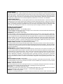
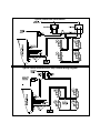
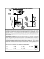
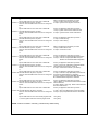
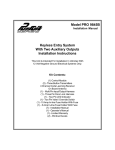
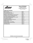
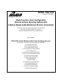
MODEL PRO-9744
INSTALLATION MANUAL
Multi Function, User Configurable
Remote Vehicle Security System with
4 Button Replaceable Membrane Remote Transmitter
This System Allows The Transmitter Buttons To Be Configured
For A Particular Vehicle, Dealer, Or Consumer
Based On Operational Preferences Or Requirements.
Kit Contents:
PRO-9744 Control Module w/Anti Code Grabbing Receiver
(2) PRO-OE4, Four Button Anti Code Grabbing Transmitters
Six Tone Multi Tone Siren
(1) 8 Pin Main Wiring Harness
(1) 10 Pin Mini Wiring Harness
(1) 3 Pin Primary Door Unlock Harness
(1) 2 Pin Plug In LED
(1) 2 Pin Plug In Valet/Program Switch
(1) 2 Pin Door Lock/2nd Unlock Harness
(1) 4 Pin Shock Sensor Harness
(1) Single Stage Shock Sensor
(1) Installation Manual
(1) Owner's Guide
(1) Transmitter Programming Guide
(1) Transmitter Wallet Card
(1) Limited Lifetime Warranty
(1) Vehicle Anti Theft Guarantee
(2) Window Warning Decals
PRO-9744
The PRO-9744 Remote Control Security System has been designed as a completely configurable system that will
meet the needs of any consumer. In addition to the many programmable features of the unit, the system offers a
transmitter membrane button replacement program. This will allows you to configure the button's of the transmitter
to coincide with configured operation of the system.
INSTALLATION OF THE MAJOR COMPONENTS:
CONTROL MODULE:
Select a mounting location inside the passenger compartment (up behind the dashboard). The mounting location
selected must insure that the module will not interfere with proper operation of the vehicle. Avoid mounting the
module to or routing the wiring around the steering shaft/column, as the module or wiring may wrap around or block
the steering wheel preventing proper control of the vehicle. Secure the module in the chosen location using cable
ties or screws as necessary.
Do Not Mount The Module In The Engine Compartment, as it is not waterproof.
SIREN:
Select a location in the engine compartment that is not accessible from below the vehicle. The selected location
must be clear of hot or moving parts within the engine compartment. The siren must be pointed downward to prevent
water retention, and the flared end must be pointed away and out of the compartment for maximum sound distribution. Before securing the siren, check behind your chosen location to assure that the mounting screws will not
penetrate any factory wiring or fluid lines. Secure the siren mounting bracket using #8 self taping screws or by first
using the mounting bracket as a template, scribe or mark the three bracket mounting holes. Drill the three marked
holes using a 1/8" drill bit, then mount the siren using #8 sheet metal screws.
HOOD AND TRUNK PIN SWITCHES:
The pin switches included in this package are intended for protecting the hood and trunk areas of the vehicle. In all
cases, the switch must be mounted to a grounded metal surface. When the pin switch is activated, (hood/trunk
open), it will supply a ground to the input wire activating the alarm. Mount the switches in the hood and trunk
locations away from water drain paths. If necessary, the included brackets may be used to move the switch away
from rain gutters or allow mounting to the firewall behind the hood seal. In both cases the switch must be set to allow
the hood or trunk door to depress the switch at least 1/4 inch when the hood or trunk is closed and, fully extended
when the hood or trunk is opened. For direct mounting, a 1/4 inch hole must be drilled. Carefully check behind the
chosen location to insure the drill will not penetrate any existing factory wiring or fluid lines. Drill a 1/4" hole in the
desired location and thread the pin switch into it using a 7/16" nut driver or deep well socket. If using the mounting
bracket, first secure the bracket to the desired location and secure the pin switch in the pre-threaded mounting
bracket hole.
DASH MOUNTED L.E.D.:
The small Red LED included in the kit will serve as a visual indicator of the alarm's status and provide a visual
deterrent to a potential thief. The LED also provides important feed back information during the transmitter and
feature program modes. The LED should be installed in the dash in an area highly visible so that it may be seen from
the drivers seat as well as from outside the vehicle. Inspect behind the chosen location to insure that the drill will not
penetrate any existing factory wiring or fluid lines. Carefully drill a 1/4" hole in the desired location and pass the
connector end of the LED through the hole and toward the control module. Press the LED firmly into place until it is
fully seated in the mounting hole.
VALET / PROGRAM / MANUAL OVERRIDE SWITCH :
Select a mounting location that is easily accessible to the operator of the vehicle. It is not necessary to conceal the
switch however concealment is recommended as it offers a higher level of security. The switch can be mounted to
the lower dash panel in the driver's area. Inspect behind the chosen location to insure that adequate clearance is
allowed for the body of the switch, as well that the drill will not penetrate any existing factory wiring or fluid lines. Drill
a 1/4" hole in the desired location and mount the switch by passing it through the panel from the underside. Secure
the switch using the nut, star washer, and on/off face plate. It is suggested that the switch be oriented to allow the on
position to be up toward the driver and the off position to be down or away from the driver. Route the switch's
connector toward the control module.
1
SHOCK SENSOR:
Select a centrally located, solid mounting surface for the shock sensor that will allow consistent operation from all
areas of the vehicle. The selected location must be within 18" of the control module to allow routing and connecting
of the 4 pin harness. Secure the shock sensor to the chosen location using two #8 self taping sheet metal screws.
The sensor can also be secured to an existing dash brace using cable tie straps. Whichever mounting method is
used be sure to allow access to the sensitivity adjustment potentiometer for use later in the installation.
STARTER INHIBIT RELAY:
Select a mounting location within 12" of the ignition switch's low current start solenoid wire. Secure the relay to an
existing harness in the chosen location using a cable tie around the relays wiring harness. Caution! Do not wire tie
the metal bracket to an existing wiring harness as vibration may cause chaffing and shorting damaging the factory
wiring. If an existing harness is not available then secure the relay's metal mounting tab to an under dash metal
brace with a #8 self taping sheet metal screw. Wire the relay as per the diagram found later in this manual.
WIRING THE CONTROL MODULE:
8 PIN MAIN WIRING HARNESS:
RED w/ WHITE Trace Wire: + 12 Volts Battery Source
The Red w/ White trace wire is the main 12 volt supply for the control module. Connect the RED wire with the 5 Amp
fuse to a constant + 12 volt battery source.
ORANGE Wire: Ground When Armed Output
This wire provides a 300 mA ground output when the alarm circuit is armed to control the starter inhibit relay.
Connect the Orange wire to terminal #86 (orange wire) of the relay provided. Connect terminal #85 (red wire) of the
relay to an ignition wire in the vehicle that is live when the ignition switch is turned to the on and start positions and
off when the key is off. Locate and cut the low current start solenoid wire found at the vehicles ignition switch
harness. This wire will have + 12 volts when the ignition key is moved to the start (crank) position and will have 0
volts in all other key positions. Connect one side of the cut wire to terminal #87a ( Black wire) of the relay. Connect
the other side of the cut wire to terminal #30 (White/Black wire) of the relay.
GREEN w/ WHITE Trace Wire: Entry Illumination Ground Output
This wire provides a 30 second ground output (300 mA Max.) ,whenever the remote is used to disarm the alarm or
to unlock the doors and, provides a continuous pulsed output whenever the alarm is triggered. This wire should be
connected to an external relay and wired to the vehicle's interior lighting circuit whenever the optional Interior Illumination circuit is desired.
DARK BLUE Wire: 300mA Channel 3 Ground Output
The Dark Blue wire supplies a 300mA ground output whenever channel three of the receiver is accessed. This
output is programmable for pulsed output or switched output and can be selected to operate from a double push of
the transmitter or a 2 second press & hold. This is a low current output and must be connected to a relay to supply
power to the trunk release or the circuit you wish to control. Connect the Dark Blue wire to terminal # 86 of a
VF45F11 P&B relay or equivalent. Connect terminal # 85 of the relay to a fused + 12 volt source. Connect the
common, normally open, and normally closed contacts of the relay to perform the selected function of channel 3. To
access this channel see section on receiver and transmitter configuration and programming shown later in this
manual.
WHITE w/ BLACK Trace Wire: + Siren Output
This is the positive siren feed wire. Route this wire through a grommet in the firewall to the siren location. Connect
the White w/ Black Trace wire to the Red wire of the Siren. Secure the Black wire of the Siren to a known chassis
ground or solid clean metal surface.
BLACK: Chassis Ground Source
Connect the Black wire to a known vehicle ground source or to a solid clean metal part of the chassis. Be certain to
remove any paint or grease and secure this wire with a self taping screw and ring terminal.
WHITE Wire: + 12 Volt Parking Light Flash Output
This wire is the normally open contact of the on board parking light flasher relay. Connect this wire to the vehicle's
parking light feed wire. This is the wire that gets + 12 volts from the parking light switch.
RED Wire: + 12 Volt Park Light Input
This is the on-board light flash relay + 12 volt input. This wire connects to the common contact of the internal relay.
2
This circuit is designed for a pulsed 15 Amp maximum current rating. Connect the Red wire with the 15 Amp fuse to
a constant + 12 volt supply. If it becomes necessary to replace the fuse in this wire, a fuse rated for 15 Amps maximum
is to be used.
WIRING THE 10 PIN MINI WIRING HARNESS
GREEN w/ BLACK Trace Wire: 300 mA Channel 6 Ground Output
The Green w/ Black Trace wire supplies 300mA pulsed ground output whenever channel 6 of the receiver is accessed. This output is pre-programmed to operate from a double push of the programmed transmitter button. This is
a low current output and must be connected to a relay to supply power to the circuit you wish to control. Connect the
Green w/ Black trace wire to terminal # 86 of a VF45F11 P&B relay or equivalent. Connect terminal # 85 of the relay
to a fused + 12 volt source. Connect the common, normally open, and normally closed contacts of the relay to
perform the selected function of control module's channel 4 output. To access this channel see section on receiver
and transmitter configuration and programming shown later in this manual. To access this channel see section on
receiver and transmitter configuration and programming shown later in this manual.
BLACK w/WHITE Trace Wire:
The Black w/ White Trace wire will provide a pulsed ground output which can be used to sound the vehicle's horn.
This is a low current (300 mA) output and must be connected to a relay for proper operation. Most vehicles have a
horn relay connected to the horn switch. If the existing relay requires less than 300 mA then direct connection to the
horn wire is possible. If the vehicle horn does not switch a existing low current relay or if the horn circuit is + 12 volts
switched, you must connect the Black w/ White Trace wire to a external relay coil. When connecting to an external
relay, connect the Black w/ White Trace wire to terminal # 86 of a P&B VF45F11 or equivalent relay. Connect terminal
# 85 to a fused +12 volt battery source. Arrange terminals # 30 & # 87 to switch ground or + 12 volts as necessary for
the horn circuit you are connecting to.
ORANGE w/WHITE Trace Wire:
The Orange w/ White Trace wire provides a ground output when the security system is disarmed. This low current
(300 mA), output may be used to control a normally open Starter Inhibit Circuit where desired. To use the Orange w/
White Trace wire, Connect the Orange w/ White Trace wire to terminal # 86 of a P&B VF45F11 or equivalent relay.
Connect terminal # 85 of the relay to an ignition wire in the vehicle that has + 12 volts when the ignition key is in the
on and start positions and has 0 volts in the off and accessory positions. Locate and cut the low current start solenoid
wire found at the vehicle's ignition switch harness. Connect terminal # 30 of the relay to the ignition switch side of the
cut wire. Connect terminal # 87 of the relay to the starter side of the cut wire.
NOTE: This normally open starter cut relay arrangement will prevent the vehicle from starting if the control module
or wiring to the control module is disconnected or removed. Audiovox does not recommend the use of this circuit to
interrupt anything but the starting circuit of the vehicle.
DARK GREEN Wire: (-) Instant Trigger Zone 2 Input
The Dark Green wire is the instant on ground trigger input wire. Connect this wire to the hood and trunk pin switches
previously installed. Note: This wire will be shunted whenever the receiver's R.F. Channels 3 or 6 are accessed, (Dark
Blue & Green w/ Black trace wires.). These wire will remain shunted all the while there is ground present, and for 5
seconds after the ground is removed. This allows the operator to open the trunk, remote start the vehicle, etc.... via
the remote transmitter without having to first disarm the alarm system.
BROWN Wire: (-) Negative Door Trigger Input
If the vehicle's door courtesy light switches ground when the door is opened, (Most GMs and Imports), Connect this
wire to the negative output from one of the vehicle's door pin switches. In most cases the Brown wire will need to be
connected to only one door switch no matter how many doors the vehicle has as most door lighting circuits are wired
in parallel.
PURPLE Wire: (+) Positive Door Trigger Input
If the vehicle's door courtesy light switches + 12 volts when the door is opened, (Most Fords and some Imports),
Connect this wire to the positive output from one of the vehicle's door pin switches. In most cases, the Purple wire will
need to be connected to only one door switch no matter how many doors the vehicle has as most door lighting circuits
are wired in parallel.
YELLOW Wire: (+) 12 Volts Ignition Switch Input
Connect this wire to a source in the vehicle that is live when the ignition switch is in the on, and start positions, and has
0 volts when the switch is turned off.
3
WHITE w/ BLUE Trace Wire: Low Current (-) Ground Headlight Output
The White w/ Blue Trace wire is provided to operate the optional headlamp illumination feature of the system. This
is a low current (300 mA) output and must be connected to an external relay to control the high current switching
circuit of the vehicle's headlamps. To use this option, Connect the White /w Blue Trace wire to terminal # 86 of a
P&B VF45F11 relay or equivalent. Connect Terminals #85 and # 30 to a fused + 12 Volts source with a current
capability equal to or in excess of the factory headlamp fuse. Connect terminal # 87 of the relay to the switched +
12 volt wire feeding the vehicle's headlamp circuit. (See receiver programming channel 4 and module programming features 1 & 2 for additional information.)
NOTE: For ground switched headlamp circuits, Connect the White /w Blue Trace wire to terminal # 86 of a P&B
VF45F11 relay or equivalent. Connect Terminal #85 to a fused + 12 Volts source. Connect terminal # 30 to a clean
chassis ground. Connect terminal # 87 to the ground switched headlamp control wire in the vehicle.
LIGHT GREEN Wire: (-) Instant Trigger Zone 1 Input
This is a instant on ground trigger input intended for the connection of optional triggering devices. The ground
trigger output wire of motion detectors, microwave detectors, or glass break detectors, can be connected to this
Light Green trigger input wire. If more than one device is connected to this wire, diode isolation may be necessary.
2 Pin LED Connector:
Plug the two pin LED connector from the previously installed LED into the mating two pin white connector shell of
the control module.
2 Pin Valet/Manual Override/Program Switch: (Blue Connector)
The Black & Grey twin lead wires loaded in the two pin blue connector are the ground supply and program/valet/
override input of the PRO-9744. When the Grey wire is grounded, under certain conditions, the unit will enter the
valet mode. When the Grey wire is sequentially grounded under other conditions, the unit will enter the various
program modes. When the switch is on, i.e.. grey wire is grounded, within 15 seconds of the ignition switch turning
on, the unit will disarm from the armed state. Route the twin lead Black and Grey wires from the Valet/Program/
Override Switch to the PRO-9744 and plug the two pin connector into the mating blue connector shell of the control
module. Refer to remote programming & feature/function programming shown later in this guide.
3 Pin Door Unlock Output Harness:
The 3 pin door unlock output harness serves as the primary (all door) unlock output, or 1st door unlock output in
a 2 step unlock circuit, depending on how the system is configured. This circuit is capable of switching up to 12
Amps and can be used to operate 3 wire ground, 3 wire positive or 5 wire alternate door unlock circuits. If you are
configuring the system for 2 step unlock, (drivers door first then all remaining doors), see diagram below. In
addition see section below referring to the 2nd unlock output.
BLUE Wire: Normally Closed Contact.
The Blue wire of the three pin connector is the normally closed contact of the primary unlock relay. If the circuit is
to be configured as a 2 step unlock system, this wire will connect to the switch side of the cut driver's door motor leg
wire as shown in the following diagrams. If the system is to be configured to unlock all doors with one transmitter
button activation, this wire will not be used for three wire switching circuits but will be used in five wire door unlock
configurations.
WHITE Wire: Common Contact
The White wire of the three pin connector is the common contact of the primary door unlock relay. If the circuit is
to be configured as a 2 step unlock system, this wire will connect to the driver's door unlock motor side of the cut
wire as shown in the following diagrams. If the system is to be configured to unlock all doors with one transmitter
button activation, this wire will connect to ground or +12 volts depending on the switching circuit used in the
vehicle.
ORANGE Wire: Open Contact
The Orange wire of the three pin connector is the normally open contact of the primary unlock relay. If the circuit is
to be configured as a 2 step unlock system, this wire will connect to a fused + 12 volt source if the vehicle switches
+ 12 volts to the drivers door unlock motor or a ground source if the vehicle switches ground to the drivers door
unlock motor. If the system is to be configured to unlock all doors with one transmitter button activation, this wire
will connect to the control wire in the vehicle's door lock circuit. See the following diagrams more details information for 2 step and single step door lock operation.
4
2 Pin Door Lock & 2nd Unlock Harness: (White Connector)
The Red & Green Door Lock & 2nd Unlock output wires provide either a pulsed ground or pulsed + 12 volts to control
the vehicle door locks & 2nd unlock circuits. The output of these wires have a maximum switching capability of
300mA. Many vehicles today have factory door lock relays which can be connected directly to these outputs,
however always confirm that the factory relays in your particular vehicle do not exceed the rated 300mA output of the
unit's door lock & 2nd unlock outputs. Plug the two pin connector of the door lock / 2nd unlock harness into the
mating 2 pin connector shell of the control module. Determine the door lock circuit of the vehicle you are working
with and wire accordingly.
NOTE: The 2nd unlock output will not be used if you are installing the system in the vehicle using a "One Step"
unlocking system. This output, in this configuration, may be used as a additional channel output but must be wired
accordingly. To access this output see the transmitter programming section shown later in this manual.
3 Wire Ground Switched Door Lock Circuits:
In this application, the Red wire of the two pin harness provides a ground pulse during the arming sequence, or
pulsed ground lock output. Connect the Red wire to the low current ground signal from the factory door lock switch
to the factory door lock relay.
The Green wire of the two pin harness provides a ground pulse during the 2nd step disarming sequence, or pulsed
ground 2nd unlock output. Connect the Green wire to the low current ground signal from the factory door unlock
switch to the factory door unlock relay.
3 Wire Positive Switched Door Locks:
In this application, the Red wire of the two pin harness provides a + 12 volt pulse during the 2nd step disarming
sequence, or pulsed 12 volt 2nd unlock output. Connect the Red wire to the low current 12 volt signal from the
factory door unlock switch to the factory door unlock relay.
The Green wire of the two pin harness provides a + 12 volt pulse during the arming sequence, or pulsed 12 volts
lock output. Connect the Green wire to the low current 12 volt signal from the factory door lock switch to the factory
door lock relay.
Note: For connection to Four Wire Polarity Reversal, 5 Wire Alternating 12 Volts, And All Other Door Lock Circuits
the Audiovox AS-9159 Door Lock Interface, or equivalent 30 A automotive Relay must be used. Refer to the
Audiovox Door Lock Wiring Supplement for proper wiring of these circuits.
Typical 5 Wire 2 Step Unlock/Lock Wiring Diagram
5
Typical 5 Wire Door Lock/Unlock
Typical 3 Wire Ground Lock/ 2 Step Unlock Wiring Diagram
6
Typical 3 Wire Ground Switched Door Lock/Unlock
Typical 3 Wire + 12 Volt Lock/ 2 Step Unlock Wiring Diagram
7
Typical 3 Wire + 12 Volt Switched Door Lock/Unlock
USING 2nd UNLOCK AS ADDITIONAL CHANNEL:
If installing the unit as a single step unlock circuit, the 2nd unlock wire is available as an auxiliary output. Program
any available transmitter button(s) into the receiver Unlock Channel #2 and, connect the unused wire Green, or
Red, of the two pin lock/2nd unlock connector to terminal #86 of a P&B VF45F11 or equivalent relay. Connect
terminal #85 of the relay to - or + 12 volts depending on the output of the 2nd unlock wire, and arrange the contacts
#30, #87a, & #87 to perform the switching function required by the device. NOTE: Programming the receiver channel #2 and module program feature #11 is necessary for proper operation also when accessing this channel, the
alarm will disarm.
PROGRAMMING THE PRO-9744:
The PRO-9744 has two program modes. One that will allow the transmitter to be configured to accommodate a
particular vehicle, consumer, or dealer, based on their preference. The second allows the module to respond to the
transmitter configuration in a particular way that will allow the door lock/unlock sequence to be controlled by either
a single button or two buttons, the panic feature to be controlled from the arm button or from a separate transmitter
button, channel 3 output to be controlled by a single button push or a double push, etc... The many transmitter
configurations are available by replacing the rubber membrane inside the transmitter case. You can choose a
particular button arrangement based on the requirement of your vehicle, dealer, or customer's preference from the
available membranes shown later in this manual or you can use the default membrane packaged with the kit.
ABOUT THE 4 BUTTON TRANSMITTER:
The 4 button transmitter produces 14 different R.F. codes that can be programmed into the receiver. The available
codes are produced by pressing one or any combination of the following button(s).
1
2
1
2
3
4
=
=
=
=
1
2
3
4
5
6
7
8
=
=
=
=
1&2
1&3
1&4
2&3
9
10
11
12
=
=
=
=
2&4
3&4
1,3,&4
2,3,&4
13 = 1,2,&3
14 = 1,2,&4
3
4
The button combination 1&2 is reserved for shock sensor delete feature leaving 13 available transmitter R.F. codes.
8
ABOUT THE PRO-9744 RECEIVER's PROGRAMMABLE FEATURES:
The PRO-9744 has six receiver slots available for programming to control various functions of the alarm system. The
programming of these receiver slots will be predicated on the transmitter membrane used and the functions desired.
The receiver slots available are as follows:
1
=
Lock and Arm (See Program Feature 11)
4
=
Headlight Operation
2
=
Unlock and Disarm
5
=
Dedicated Panic Button
3
=
Channel 3 Output (Trunk Release)
6
=
Channel 4 Output (Remote Start)
PROGRAMMING THE TRANSMITTERS:
Action
With the valet switch in the off position
Turn the ignition switch to the on position
Flip the valet switch on, off, on, off, on, then off
Press and hold the lock button on the transmitter
until a long siren chirp is heard, repeat for each transmitter
OR,
Flip the valet switch on then off.
Press and hold the unlock button on the transmitter
until a long siren chirp is heard, repeat for each transmitter
OR,
Flip the valet switch on then off.
Press and hold the transmitter button with the trunk
symbol on it until a long siren chirp is heard, repeat
for each transmitter
OR,
Flip the valet switch on then off.
Press and hold the transmitter button with the headlight symbol on it or, any unused button(s) you wish
to control activation of the headlights until a long siren chirp is heard, repeat for each transmitter
OR,
Flip the valet switch on then off.
Press and hold the Red transmitter panic button with
the circles on it or any unused button(s) you wish to
dedicate for the panic feature until a long siren chirp
is heard, repeat for each transmitter. Note: The
factory default transmitter button for the panic feature will be controlled from the arm button unless
otherwise programmed,
OR,
Flip the valet switch on then off.
Press and hold the transmitter button with the (start)
key symbol on it or any unused button(s) you wish to
control activation of the Green w/ Black trace wire's
output until a long siren chirp is heard, repeat for
each transmitter. Note: This channel requires a
double push within 5 seconds to activate the output.
OR,
Flip the valet switch on then off to exit the program
mode, or turn the ignition switch off to exit the program mode
System Response
Receiver Channel # & Function
Siren 1 chirp, LED 1 flash...
Channel 1 = Lock & Arm
Siren 2 chirps, LED 2 flashes...
Channel 2 = Unlock & Disarm
Siren 3 chirps, LED 3 flashes...
Channel 3 = module's output Dark
Blue wire (Trunk Release) can be
programmed for 1 second pulse or
output as long as TX. button is
pressed.
Channel 4 = R.F. Headlight activation from dedicated transmitter button.
Siren 4 chirps, LED 4 flashes...
Siren 5 chirps, LED 5 flashes...
Channel 5 = Dedicated transmitter
panic button. (See module programmable feature #9)
Siren 6 chirps, LED 6 flashes...
Channel 6 = module's output Green
w/Black trace wire (Remote Start) requires double push of programmed
transmitter button
Siren one long and one short
chirp.
Exit Program mode
9
PROGRAMMABLE FEATURES REFERENCE CHART:
FEATURE:
DESCRIPTION:
1
Headlights turn on for 20 seconds when Disarming.
SIREN REPORT:
1 Chirp on
2 Chirps off
LED REPORT:
1 Flash Pause, etc...
2
Headlights turn on for 20 seconds when
Arming
1 Chirp on
2 Chirps off
2 Flash Pause, etc...
3
Ignition Lock Select
1 Chirp on
2 Chirps off
3 Flash Pause, etc...
4
Ignition Unlock Select
1 Chirp on
2 Chirps off
4 Flash Pause, etc...
5
Ignition Unlock Dr. Door or All Doors
1 Chirp Dr. Door
2 Chirps All Doors
5 Flash Pause, etc...
6
Active or Passive Arming
1 Chirp Passive
2 Chirps Active
6 Flash Pause, etc...
7
Active or Passive Door Locks
1 Chirp Passive
2 Chirps Active
7 Flash Pause, etc...
8
Channel 3 Output select pulsed or as long
as tx. button held, (up to 8 seconds)
1 Chirp Pulsed
2 Chirps As Long As Held
8 Flash Pause, etc...
9
Panic from channel 1 or channel 5.
(See tx. programming #5)
1 Chirp Channel 5
2 Chirps Channel 1
9 Flash Pause, etc...
10
Hold Tx. Button 2 Seconds or, Press 2 X to
activate Channel 3 Output
1 Chirp Hold 2 seconds
2 Chirps Press 2X
10 Flash Pause, etc...
11
2 Button two Step Unlock or, 1 Button two
step Unlock
1 Chirp 2 Button Two Step
2 Chirps 1 Button Two step
11 Flash Pause, etc...
12
RF Chirp Eliminate
1 Chirp Chirp On
2 Chirps Chirp Off
12 Flash Pause, etc...
PROGRAMMING THE CONTROL MODULE:
Feature: Action and LED Flash Response:
Chirps Indicate:
Start with the valet switch in the off position.
Turn the ignition switch on.
Flip the valet switch on, off, on, off, on, then off.
The siren chirps one time.
Immediately turn the ignition switch off then on.
Feature 1 The siren will emit 1 short chirp followed by 1 long chirp,
followed by one or two chirps, The LED will flash 1 x
pause, 1x pause... indicating you are now in feature #1
program mode.
If when you turned the ignition switch on, you heard:
Press the arm transmitter button one time to change this *1 Chirp = The Headlights Will Turn On For 20 Seconds When
Disarming*
feature
2 Chirps = The Headlights Will Not Turn On When Disarming
or,
Flip the valet switch on then off to move to feature #2.
The LED will flash 2x pause, 2x pause...
Feature 2
Press the arm transmitter button one time to change this
feature
or,
Flip the valet switch on then off to move to feature #3.
The LED will flash 3x pause, 3x pause...
Feature 3 Press the arm transmitter button one time to change this
feature
10
If when you flipped the valet switch you heard:
1 Chirp = The Headlights Will Turn On For 20 Seconds When
Arming
*2 Chirps = The Headlights Will Not Turn On When Arming*
If when you flipped the valet switch you heard:
*1 Chirp = Ignition Control Lock On*
2 Chirps = Ignition Control Locks Off
Feature 4
Feature 5
Feature 6
Feature 7
Feature 8
Feature 9
Feature 10
Feature 11
Feature 12
or,
Flip the valet switch on then off to move to feature #4.
The LED will flash 4x pause, 4x pause...
Press the arm transmitter button one time to change this
feature
or,
Flip the valet switch on then off to move to feature #5.
The LED will flash 5x pause, 5x pause...
Press the arm transmitter button one time to change this
feature
or,
Flip the valet switch on then off to move to feature #6.
The LED will flash 6x pause, 6x pause...
Press the arm transmitter button one time to change this
feature
or,
Flip the valet switch on then off to move to feature #7.
The LED will flash 7x pause, 7x pause...
Press the arm transmitter button one time to change this
feature
or,
Flip the valet switch on then off to move to feature #8.
The LED will flash 8x pause, 8x pause...
Press the arm transmitter button one time to change this
feature
or,
Flip the valet switch on then off to move to feature #9.
The LED will flash 9x pause, 9x pause...
Press the arm transmitter button one time to change this
feature
or,
Flip the valet switch on then off to move to feature #10.
The LED will flash 10x pause, 10x pause...
Press the arm transmitter button one time to change this
feature
or,
Flip the valet switch on then off to move to feature #11.
The LED will flash 11x pause, 11x pause...
Press the arm transmitter button one time to change this
feature
or,
Flip the valet switch on then off to move to feature #12.
The LED will flash 12x pause, 12x pause...
Press the arm transmitter button one time to change this
feature
or,
Flip the valet switch on then off to exit the program mode,
or, turn the ignition switch off to exit the program mode.
If when you flipped the valet switch you heard:
1 Chirp = Ignition Control Ignition Unlock On
*2 Chirps = Ignition Control Ignition Unlock Off*
If when you flipped the valet switch you heard:
1 Chirp = Ignition Control Unlock Of Drivers Door.
*2 Chirps = Ignition Control Unlock Of All Doors*
If when you flipped the valet switch you heard:
*1 Chirp = Passive Arming*
2 Chirps = Active Arming
If when you flipped the valet switch you heard:
1 Chirp = Passive Door Locks
*2 Chirps = Active Door Locks*
If when you flipped the valet switch you heard:
*1 Chirp = Channel 3 Output (Dark Blue Wire) Pulsed*
2 Chirps = Channel 3 Output (Dark Blue Wire) For
Duration Of Transmitter Button Depression.
If when you flipped the valet switch you heard:
1 Chirp = Panic From Independent Transmitter Button.
(See transmitter programming channel 5)
*2 Chirps = Panic From Channel 1 (arm button)*
If when you flipped the valet switch you heard:
*1 Chirp = Channel 3 output (Dark Blue) 2 Second Push
And Hold Transmitter Button For Activation.*
2 Chirps = Channel 3 Output (Dark Blue) Double Push
Of Transmitter Button Required For Activation.
If when you flipped the valet switch you heard:
1 Chirp = Button 1 Lock All & Unlock Drivers Door. Button
2 Unlock All Doors.
*2 Chirps = Button 1 Lock Only. Button 2 Unlock Driver's
Door & All Other Doors.*
If when you flipped the valet switch you heard:
*1 Chirp = (R.F.) Chirp Eliminate On From Transmitter.*
2 Chirps = (R.F.) Chirp Eliminate Off From Transmitter.
1 Long Chirp
1 Long Chirp
NOTE: Features enclosed in Asterisk (*) indicate factory default setting.
11
ORANGE
BLUE
12
128-5039A
13