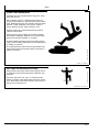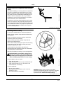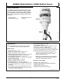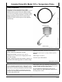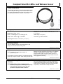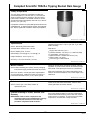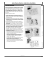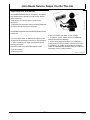
1
*DCY*
*OMPFP15006*
John Deere Field Connect™
OPERATOR'S MANUAL
John Deere Field Connect™
OMPFP15006 ISSUE J4
(ENGLISH)
CALIFORNIA
Proposition 65 Warning
Diesel engine exhaust and some of its constituents
are known to the State of California to cause cancer,
birth defects, and other reproductive harm.
If this product contains a gasoline engine:
The engine exhaust from this product contains
chemicals known to the State of California to cause
cancer, birth defects or other reproductive harm.
The State of California requires the above two warnings.
Additional Proposition 65 Warnings can be found in this manual.
John Deere Ag Management Solutions
PRINTED IN U.S.A.
*ompfp15006*
WARNING
Introduction
Foreword
WELCOME to the John Deere Field Connect™ system
offered by John Deere.
READ THIS MANUAL carefully to learn how to operate and
service your system correctly. Failure to do so could result
in personal injury or equipment damage. This manual and
safety signs on your machine may also be available in
other languages. (See your John Deere dealer to order.)
THIS MANUAL SHOULD BE CONSIDERED a permanent
part of your system and should remain with the system
when you sell it.
RECORD PRODUCT IDENTIFICATION NUMBERS
(P.I.N.). Accurately record all the numbers to help in
tracing the components should they be stolen. Your dealer
also needs these numbers when you order parts. File the
identification numbers in a secure place off the machine.
WARRANTY is provided as part of John Deere's support
program for customers who operate and maintain their
equipment as described in this manual. The warranty is
explained on the warranty certificate which you should
have received from your dealer.
This warranty provides you the assurance that John
Deere will back its products where defects appear within
the warranty period. In some circumstances, John Deere
also provides field improvements, often without charge
to the customer, even if the product is out of warranty.
Should the equipment be abused, or modified to change
its performance beyond the original factory specifications,
the warranty will become void and field improvements
may be denied.
John Deere Field Connect is a trademark of Deere & Company
RM72004,00001ED -19-17SEP13-1/1
www.StellarSupport.com
NOTE: Product functionality may not be fully represented in this document due to product changes occurring after the time of printing. Read
the latest Operator's Manual prior to operation. To obtain a copy, see your dealer or visit www.StellarSupport.com
CZ76372,000071F -19-18JUN14-1/1
www.AirmarTechnology.com
For additional information about the AIRMAR® WeatherStation® 150WX weather sensor, visit www.AirmarTechnology.com.
AIRMAR and WeatherStation are registered trademarks of
Airmar Technology Corporation
RM72004,00001DD -19-05SEP13-1/1
www.campbellsci.com
For additional information on these Campbell Scientific® products–107-L Temperature Probe, CS300-L Pyranometer, LWS-L Leaf Wetness Sensor,
and TE525-L Tipping Bucket Rain Gauge, visit www.campbellsci.com.
Campbell Scientific is a registered trademark of Campbell Scientific, Inc.
HC94949,0000255 -19-05MAR13-1/1
Read This Manual
Before installing soil moisture probe, gateway,
environmental sensors, operating data collection,
and display features, read this manual to learn proper
installation and operating procedures.
RM72004,00001DC -19-14OCT13-1/1
Notifications to User
These devices must be operated as supplied by John
Deere Ag Management Solutions. Any changes or
modifications made to these devices without the express
written approval of John Deere Ag Management Solutions
may void the user’s authority to operate these devices.
BA31779,00006FC -19-25OCT13-1/1
102914
PN=2
Introduction
FCC Notifications to User
John Deere Field Connect™
This device complies with part 15 of the FCC Rules.
Operation is subject to the following two conditions: (1)
This device may not cause harmful interference, and
(2) this device must accept any interference received,
including interference that may cause undesired operation.
Field Connect™ Gateway and Moisture Probe
This equipment has been tested and found to comply with
the limits for a Class A digital device, pursuant to part 15
of the FCC Rules. These limits are designed to provide
reasonable protection against harmful interference when
the equipment is operated in a commercial environment.
This equipment generates, uses, and can radiate radio
frequency energy and, if not installed and used in
accordance with the instruction manual, may cause
harmful interference to radio communications. Operation
of this equipment in a residential area is likely to cause
harmful interference in which case the user will be
required to correct the interference at his own expense.
Field Connect™ Gateway Modem and Airmar
Weather Sensor
This equipment has been tested and found to comply with
the limits for a Class B digital device, pursuant to part 15
of the FCC Rules. These limits are designed to provide
reasonable protection against harmful interference in
a residential installation. This equipment generates,
uses and can radiate radio frequency energy and, if not
installed and used in accordance with the instructions,
may cause harmful interference to radio communications.
However, there is no guarantee that interference a
particular installation. If this equipment does cause
harmful interference to radio or television reception, which
can be determined by turning the equipment off and on,
the user is encouraged try to correct the interference by
one or more of the following measures:
• Reorient or relocate the receiving antenna.
• Increase the separation between the equipment and
receiver.
BA31779,00006FB -19-29OCT13-1/1
102914
PN=3
Introduction
PC17927 —UN—29OCT13
Industry Canada Notifications to User
Continued on next page
BA31779,00006FD -19-28OCT13-1/2
102914
PN=4
PC17928 —UN—28OCT13
Introduction
BA31779,00006FD -19-28OCT13-2/2
102914
PN=5
Introduction
102914
PN=6
Contents
Page
Page
Safety
Recognize Safety Information ............................05-1
Understand Signal Words...................................05-1
Follow Safety Instructions...................................05-1
Practice Safe Maintenance.................................05-2
Use Steps and Handholds Correctly ..................05-2
Handle Electronic Components and
Brackets Safely ..............................................05-3
Handling Batteries Safely ...................................05-3
Avoid Buried Utility Lines....................................05-4
Avoid Exposure to High Radio
Frequency Fields............................................05-4
Waste Electrical and Electronic Equipment........05-4
Viewing Environmental Sensor Data
View Environmental Sensor Data.......................40-1
AIRMAR WeatherStation 150WX Weather Sensor
Theory of Operation............................................45-1
Specifications .....................................................45-1
Mounting Location ..............................................45-2
Maintenance .......................................................45-2
External Cleaning Of Probe, Sensors,
and Gateway ..................................................45-2
Troubleshooting..................................................45-2
Overview
Campbell Scientific Model 107–L Temperature
Probe
System Overview................................................10-1
Glossary .............................................................10-1
Theory of Operation............................................50-1
Specifications .....................................................50-1
Mount Location ...................................................50-1
Maintenance .......................................................50-2
External Cleaning Of Probe, Sensors,
and Gateway ..................................................50-2
Troubleshooting..................................................50-2
Components
Required Components........................................15-1
Battery ................................................................15-4
Connectors
Antenna Connections .........................................20-1
Field Connect™ Gateway Ports .........................20-2
Soil Moisture Probe Connection .........................20-3
Campbell Scientific CS300-L Pyranometer
Theory of Operation............................................55-1
Specifications .....................................................55-1
Mounting Location ..............................................55-1
Maintenance .......................................................55-1
External Cleaning Of Probe, Sensors,
and Gateway ..................................................55-1
Troubleshooting..................................................55-2
Website
Compatibility .......................................................25-1
Images................................................................25-1
Login...................................................................25-1
Website Navigation.............................................25-1
Campbell Scientific LWS-L Leaf Wetness Sensor
Specifications
Theory of Operation............................................60-1
Specifications .....................................................60-1
Mounting Location ..............................................60-1
Maintenance .......................................................60-1
External Cleaning Of Probe, Sensors,
and Gateway ..................................................60-1
Troubleshooting..................................................60-2
Field Connect™ Gateway...................................30-1
EC Declaration of Conformity .............................30-3
EC Declaration of Conformity .............................30-4
EC Declaration of Conformity .............................30-5
EC Declaration of Conformity .............................30-6
EC Declaration of Conformity .............................30-7
EC Declaration of Conformity .............................30-8
EC Declaration of Conformity .............................30-9
Campbell Scientific TE525-L Tipping Bucket Rain
Gauge
Manual Firmware Update
Theory of Operation............................................65-1
Specifications .....................................................65-1
Manual Firmware Update ...................................35-1
Continued on next page
Original Instructions. All information, illustrations and specifications in this
manual are based on the latest information available at the time of publication.
The right is reserved to make changes at any time without notice.
COPYRIGHT © 2014
DEERE & COMPANY
Moline, Illinois
All rights reserved.
A John Deere ILLUSTRUCTION ® Manual
i
102914
PN=1
Contents
Page
Mount Location ...................................................65-1
Maintenance .......................................................65-1
External Cleaning Of Probe, Sensors,
and Gateway ..................................................65-1
Troubleshooting..................................................65-2
End of Year Best Practices
Website...............................................................70-1
Hardware ............................................................70-1
Storage ...............................................................70-2
Archive and Data Management ..........................70-2
ii
102914
PN=2
Safety
Recognize Safety Information
This is a safety-alert symbol. When you see this symbol
on your machine or in this manual, be alert to the potential
for personal injury.
T81389 —UN—28JUN13
Follow recommended precautions and safe operating
practices.
DX,ALERT -19-29SEP98-1/1
Understand Signal Words
A signal word—DANGER, WARNING, or CAUTION—is
used with the safety-alert symbol. DANGER identifies the
most serious hazards.
TS187 —19—30SEP88
DANGER or WARNING safety signs are located near
specific hazards. General precautions are listed on
CAUTION safety signs. CAUTION also calls attention to
safety messages in this manual.
DX,SIGNAL -19-03MAR93-1/1
Follow Safety Instructions
TS201 —UN—15APR13
Carefully read all safety messages in this manual and on
your machine safety signs. Keep safety signs in good
condition. Replace missing or damaged safety signs. Be
sure new equipment components and repair parts include
the current safety signs. Replacement safety signs are
available from your John Deere dealer.
There can be additional safety information contained on
parts and components sourced from suppliers that is not
reproduced in this operator's manual.
Learn how to operate the machine and how to use controls
properly. Do not let anyone operate without instruction.
Keep your machine in proper working condition.
Unauthorized modifications to the machine may impair the
function and/or safety and affect machine life.
If you do not understand any part of this manual and need
assistance, contact your John Deere dealer.
DX,READ -19-16JUN09-1/1
05-1
102914
PN=9
Safety
Practice Safe Maintenance
Understand service procedure before doing work. Keep
area clean and dry.
Never lubricate, service, or adjust machine while it is
moving. Keep hands, feet , and clothing from power-driven
parts. Disengage all power and operate controls to relieve
pressure. Lower equipment to the ground. Stop the
engine. Remove the key. Allow machine to cool.
Securely support any machine elements that must be
raised for service work.
Keep all parts in good condition and properly installed.
Fix damage immediately. Replace worn or broken parts.
Remove any buildup of grease, oil, or debris.
On towed implements, disconnect wiring harnesses from
tractor before servicing electrical system components or
welding on machine.
TS218 —UN—23AUG88
On self-propelled equipment, disconnect battery ground
cable (-) before making adjustments on electrical systems
or welding on machine.
DX,SERV -19-17FEB99-1/1
Prevent falls by facing the machine when getting on and
off. Maintain 3-point contact with steps, handholds, and
handrails.
Use extra care when mud, snow, or moisture present
slippery conditions. Keep steps clean and free of grease
or oil. Never jump when exiting machine. Never mount or
dismount a moving machine.
T133468 —UN—15APR13
Use Steps and Handholds Correctly
DX,WW,MOUNT -19-12OCT11-1/1
05-2
102914
PN=10
Safety
Handle Electronic Components and Brackets
Safely
TS249 —UN—23AUG88
Falling while installing or removing electronic components
mounted on equipment can cause serious injury. Use a
ladder or platform to easily reach each mounting location.
Use sturdy and secure footholds and handholds. Do not
install or remove components in wet or icy conditions.
If installing or servicing a RTK base station on a tower or
other tall structure, use a certified climber.
If installing or servicing a global positioning receiver mast
used on an implement, use proper lifting techniques and
wear proper protective equipment. The mast is heavy and
can be awkward to handle. Two people are required when
mounting locations are not accessible from the ground
or from a service platform.
DX,WW,RECEIVER -19-24AUG10-1/1
Handling Batteries Safely
Do not open a sealed battery to check electrolyte level.
Battery gas can explode. Keep sparks and flames away
from batteries.
Never check battery charge by placing a metal object
across the posts. Use a voltmeter.
Always remove grounded (-) battery clamp first and
replace grounded clamp last.
PC15538 —UN—18JUL12
Sulfuric acid in battery electrolyte is poisonous and strong
enough to burn skin, eat holes in clothing and cause
blindness if splashed into eyes.
Avoid hazards by using battery manufacturer’s
instructions and this manual for proper use, maintenance
and replacement of sealed battery.
Dispose of the battery according to your local regulations.
CAUTION: Battery can explode, causing serious
injury to you or others. Only replace battery with
approved replacement type (see your John Deere
dealer and Battery Specifications in this manual).
TS204 —UN—15APR13
If acid is spilled on skin or in eyes:
1. Flush skin with water.
2. Apply backing soda or lime to help neutralize the acid.
3. Flush eyes with water for 15 – 20 minutes. Get
medical attention immediately.
If acid is swallowed:
1. Do not induce vomiting.
2. Drink large amounts of water or milk, but do not
exceed 2 L (2 qt.).
3. Get medical attention immediately.
WARNING: Battery posts, terminals, and related
accessories contain lead and lead compounds, chemicals
known to the State of California to cause cancer and
reproductive harm. Wash hands after handling.
BA31779,00004E7 -19-14NOV12-1/1
05-3
102914
PN=11
Avoid Buried Utility Lines
Digging through gas, electric, or water lines can cause
serious injury or death to you or others. Contact local
utility companies to determine and mark off location of
gas, electric, or water lines before digging.
PC18243 —UN—17DEC13
Safety
HC94949,0000462 -19-17DEC13-1/1
Prevent injury from exposure to high radio frequency fields
at the Field Connect Gateway. Do not touch the antennas
while the system is transmitting. Always disconnect power
to the Gateway before installing or servicing.
While using the Field Connect Gateway, stay at least 20
cm (8 in.) away from the antennas.
PC12632 —UN—04JUN10
Avoid Exposure to High Radio Frequency
Fields
BA31779,00004E9 -19-17JUL12-1/1
Waste Electrical and Electronic Equipment
Products marked with the crossed-out wheeled bin symbol
indicate electrical and electronic equipment that must not
be disposed of as unsorted municipal or household waste.
PC17530 —UN—06AUG13
Send electrical and electronic equipment, accessories
and packaging for environmental recycling.
RM72004,00001E6 -19-05AUG13-1/1
05-4
102914
PN=12
Overview
System Overview
Theory of Operation
The John Deere Field Connect™ system allows operators
to measure, store, and analyze multiple types of field data.
Soil moisture probe and environmental sensors measure
key inputs, including soil moisture and environmental
conditions. Cellular and satellite communication
technologies support data uploads.
Field Connect™ technology enhances the ability to
manage water usage and related inputs to maximize
yields, getting more output with the same, or less input.
• Telematics gateway
• Solar panel
• Satellite antenna
• Cellular antenna
• Wiring harnesses
• Battery
Optional Components
• AIRMAR WeatherStation 150WX Weather Sensor
• Campbell Scientific 107-L Temperature Probe
• Campbell Scientific CS300-L Pyranometer
• Campbell Scientific LWS-L Leaf Wetness Sensor
• Campbell Scientific TE525-L Tipping Bucket Rain Gauge
Components
• 0.5 m, 1 m, or 1.5 m soil moisture probe
BA31779,00006E0 -19-29OCT13-1/1
Glossary
Field–Used as a grouping of management zones.
Provides a name that describes reason for the grouping.
organization; Field Connect™ supports dealer and
customer accounts.
Soil Moisture Probe–Hardware installed in field soil.
Gateway–Hardware used for consolidating information
from soil moisture probe and sensors. Gateway transmits
information for display in a web application.
• Contains multiple soil moisture sensors measuring soil
Land–Specific to an organization, includes multiple fields
and management zones.
probe connected, but a soil moisture probe cannot be
connected to more than one gateway at a time.
Management Zone–Physical region used to manage
data. Data collected from a soil moisture pobe or sensor
is stored relative to management zone.
moisture at different soil depths.
• Attaches to a gateway for data transmission.
• Each gateway can have more than one soil moisture
User Account–Login credentials and identification
information for a specific person in a system. User login
credentials allow access to an organizational account.
Organizational Account–A virtual location for user and
equipment data. An account represents an individual
RM72004,00001DA -19-29OCT13-1/1
10-1
102914
PN=13
Components
Required Components
System is composed of several on-board components.
Gateway is primary component, which houses data
processing and communications equipment. Antennas,
soil moisture probe, and environmental sensors connect
to gateway through external communication ports.
Field Connect™ Gateway
Gateway contains:
• Main processor
• Cellular and satellite modem
• Cellular and GPS antenna
• Satellite antenna
• Solar panel
• Battery
• Communications ports
Gateway acquires measurement data from soil moisture
probe and environmental sensors. Data is collected at 30
min. intervals and stored until data is uploaded.
PC17605 —UN—04SEP13
Gateway transmits data to a central, web-based
management tool using cellular or satellite
communications. Data calls occur every 2 hr. If data
communication fails, data is stored until next successful
call.
BA31779,0000361 -19-29OCT13-1/4
GSM Cellular and GPS Antenna
NOTE: Without clear view of sky at installation site,
GPS accuracy is degraded. Follow installation
guidelines provided in John Deere Field Connect™
Installation Instructions.
A single antenna serves GSM cellular data transmission
and GPS signal reception.
PC12641 —UN—11JUN10
Two coaxial cables, one for GSM cellular and one for GPS,
connect to antenna within a single mounting enclosure.
Continued on next page
15-1
BA31779,0000361 -19-29OCT13-2/4
102914
PN=14
Components
Satellite Antenna
NOTE: Without clear view of sky at installation site,
GPS accuracy is degraded. Follow installation
guidelines provided in John Deere Field Connect™
Installation Instructions.
Satellite Coverage
John Deere Field Connect™ system primarily uses cellular
signals to send information. In poor or no cellular coverage
areas, system uses satellite signals to send information.
To check if there are gaps in satellite coverage, go to:
PC14727 —UN—20FEB12
http://orbservices.orbcomm.net/WH/DisplayCoverageMap
Continued on next page
15-2
BA31779,0000361 -19-29OCT13-3/4
102914
PN=15
Components
Field Connect™ Soil Moisture Probe
NOTE: Improperly installed soil moisture probe degrades
soil moisture data. Complete tube-to-soil contact
is required for accurate measurements. Follow
installation guidelines provided in John Deere
Field Connect™ Installation Instructions.
Soil moisture probe components are calibrated
for data accuracy when manufactured. Do not
install sensor array in different housing. Data
accuracy will be affected. Contact your John
Deere dealer if soil moisture probe housing or
sensor array have been damaged.
To open Soil Moisture Probe housing, use a
30 mm socket on square nut on top of housing
cap. When closing soil moisture probe housing,
torque cap to 16.4 N·m (145 lb.-in.).
PC17736 —UN—23SEP13
Store between -40 °C (-40 °F) and 70 °C (158
°F). Store soil moisture probe in a secure,
vertical, or horizontal position. Do not store
at an angle. See End of Year Best Practices
section for more information.
Soil moisture probe is a key component of system. The
soil moisture probe places a sensor array in the crop root
zone to facilitate direct, accurate measurement of soil
moisture at multiple depths. Sensor array is calibrated to
tube housing of soil moisture probe when it is installed.
Do not install a sensor array in a different housing.
Sensor array is a capacitance sensor; complete
tube-to-soil contact is required for accurate measurements.
Soil Moisture Probe Length
0.5 m (1.64 ft.)
1.0 m (3.28 ft.)
1.5 m (4.92 ft.)
Number of Sensors
Sensor Depths
4
10 cm (4 in.)
20 cm (8 in.)
30 cm (12 in.)
50 cm (20 in.)
5
10 cm (4 in.)
20 cm (8 in.)
30 cm (12 in.)
50 cm (20 in.)
100 cm (40 in.)
6
10 cm (4 in.)
20 cm (8 in.)
30 cm (12 in.)
50 cm (20 in.)
100 cm (40 in.)
150 cm (60 in.)
BA31779,0000361 -19-29OCT13-4/4
15-3
102914
PN=16
Components
Battery
Set battery charger at nominal 12 V and
not more than 16 V.
NOTE: Charge battery before first use.
A solar panel is part of Field Connect™ system to keep
battery charged.
If battery voltage drops below 11.5 V, gateway stops
transmitting data. When charging raises battery voltage
above 12.2 V, data transmissions begin again. If system
voltage drops below 10.5 V, system goes into hibernation
mode. If hibernation occurs, go to gateway and select
multifunction button to restore system.
Service
IMPORTANT: The battery is sealed. Do not
attempt to refill the battery.
Proper battery maintenance is vital to
dependable service. Keep batteries clean.
Keep all connections clean and tight. Remove
any corrosion, and wash terminals with
baking soda and water. Coat with grease
before attaching cables.
Do not short across battery terminals.
Keep batteries fully charged, especially during
cold weather. Disconnect and remove battery
when not used for 30 days or longer.
NOTE: Due to the self-discharge characteristics of
this type of battery, it is imperative that the
battery be charged within six months of storage,
otherwise permanent loss of capacity can
occur as a result of sulfation.
1. Disconnect battery terminals from gateway.
2. With charger in off position, connect positive charger
lead to positive terminal. Connect negative charger
lead to negative terminal.
3. Switch charger on and charge battery according to
charger instructions.
4. Switch charger off. Disconnect negative charger lead,
then positive lead.
Cycle Applications: Limit initial current to 3.6 A. Charge
until battery voltage (under charge) reaches 14.4–14.7 V
at 20 °C (68 °F). Hold at 14.4–14.7 V until current drops
to under 120 mA. Battery is fully charged under these
conditions. Disconnected charger or switch to “float”
voltage.
“Float” or “Stand-By” Service: Hold battery across
constant voltage source of 13.5–13.8 V.
Battery Specifications
Store batteries below 27 °C (81 °F) for maximum
shelf life. Check voltage after storage,
and recharge as needed, as recommended
by battery manufacturer.
Type
ES12-12
Nominal Voltage
12 V
Nominal Capacity
12 Ah / 20 HR
Height
94 mm (3.7 in.)
Do not store batteries in discharged state or
stack batteries on top of each other.
Length
151 mm (5.9 in.)
Width
98 mm (3.9 in.)
Max. Charge Current
3.6 A
Charging Battery
IMPORTANT: Do not use a booster battery or
attempt to jump the battery.
BA31779,0000362 -19-20OCT14-1/1
15-4
102914
PN=17
Connectors
Antenna Connections
Cables attached to the Field Connect™ gateway for
cellular (A), GPS (B), and satellite (C) services use coaxial
TNC connectors. To prevent incorrect connections, GPS
and cellular cables have different connectors. GPS
connector is a TNC plug and cellular connector is a TNC
receptacle. The matching connectors for cellular and GPS
are integrated into antenna cable.
Satellite connection utilizes a single, coaxial TNC
receptacle connector for antenna. The matching
connector is integrated into antenna cable.
PC15225 —UN—24SEP12
NOTE: Cellular (A) and satellite antenna cables (C)
have same TNC connector receptacles and can
be connected to incorrect connector on gateway.
When connecting antenna cables to gateway,
verify correct antenna cables connect to correct
gateway bulk head connectors.
A—Cellular Antenna Coax
Connection (CELL)
B—GPS Antenna Connection
(GPS)
C—Satellite Radio Whip
Antenna Coax Connection
(SAT)
RM72004,00001EC -19-29OCT13-1/1
20-1
102914
PN=18
Connectors
Field Connect™ Gateway Ports
NOTE: Record port connection for soil moisture probe and
each environmental sensor. Some port connections
must be entered in website when completing
installation of Field Connect™ hardware.
There are 16 ports located on side of gateway. Use ports
to connect soil moisture probe and environmental sensors
to gateway.
I— FRQ 1
J— FRQ 2
K—SER 1
L— SER 2
M—SMP 1
N—SMP 2
O—AUX 1
P—AUX 2
PC17564 —UN—08AUG13
A—DIG 1
B—DIG 2
C—DIG 3
D—DIG 4
E—ALG 1
F— ALG 2
G—ALG 3
H—ALG 4
BA31779,00006A8 -19-29OCT13-1/1
20-2
102914
PN=19
Connectors
Soil Moisture Probe Connection
NOTE: Do not activate probe before connecting
it to gateway.
PC15537 —UN—16JUL12
Before installing soil moisture probe in ground, connect
harness to soil moisture probe. Soil moisture probe uses a
keyed connector. Use proper alignment when connecting
harness to soil moisture probe.
BA31779,0000363 -19-21OCT13-1/1
20-3
102914
PN=20
Website
Compatibility
pages or data from site. A list of compatible browsers
is located under the Help section on Field Connect™
website.
Web Browsers
Use a compatible browser to view John Deere Field
Connect™ website. Unlisted browsers may not render
RM72004,00001D8 -19-29OCT13-1/1
Images
Images from John Deere Field Connect™ website used in
this manual change without notice on John Deere Field
Connect™ website.
Always refer to website Help and “What’s New” for current
instructions.
RM72004,00001DB -19-29OCT13-1/1
Login
Go to http://myjohndeere.deere.com and select Field
Connect™ to access Field Connect™ website. Enter
valid user name and password to access Field Connect™
website. Operators with access to one organization
are taken to organization account. If an operator has
access to multiple organizations, select one organization
from dropdown list. Dropdown list contains all available
organizations.
A Demo Login button is available to view Field Connect™
website in demo mode. Not all features are available in
demo mode.
BA31779,00006FA -19-29OCT13-1/1
PC17397 —UN—17OCT14
Website Navigation
Field Connect™ User Guide
For navigation information within Field Connect™ website,
select Help (A) to display Field Connect™ User Guide.
A—Help
CZ76372,000072A -19-17OCT14-1/1
25-1
102914
PN=21
Specifications
Field Connect™ Gateway
Electrical
• Input Voltage—Range, 9–16 V
• Fuse—Protect device with 5 A fuse.
Battery
• Nominal Voltage—12 V
• Rated Capacity—12.0 Ah/0.60 A (20 hr., 1.8 V/cell, at
PC17702 —UN—20SEP13
25 °C (77 °F))
LED Display
A—CELL
B—GPS
C—SAT
D—BATT
E—DIG 1–4
F— FAULT
LED
G—ALG 1–4
H—FRQ 1, 2
I— USB (Multi-colored LED)
J— SER 1, 2
K—SMP 1, 2
LED Display
STATE
Solid
CELL (A)
Blinking
Off
Solid
GPS (B)
Blinking
Off
Solid
SAT (C)
BATT (D)
Blinking
Blinking
Blinking
Blinking
Off
Solid
Blinking
Off
Solid
Blinking
Off
Solid
FAULT (F)
ALG 1 (G)
Blinking
Attempting connection or unable to connect
Critical power state
Unit not powered
Device present
Channel enabled; no device detected
Channel disabled
Device present
Channel enabled; no device detected
Channel disabled
Device present
Channel enabled; no device detected
Channel disabled
Device present
Channel enabled; no device detected
Channel disabled
N/A
Urgent Fault
Off
No Fault Active
Solid
Device present
Blinking
Off
Solid
ALG 2 (G)
Device not enabled
Connection established
Device not enabled
Solid
DIG 4 (E)
Attempting connection or unable to connect
Battery connected
Off
DIG 3 (E)
Device not enabled
Connection established
Solid
Solid
DIG 2 (E)
Attempting connection or unable to connect
Off
Off
DIG 1 (E)
DESCRIPTION
Connection established
Blinking
Off
Channel enabled; no device detected
Channel disabled
Device present
Channel enabled; no device detected
Channel disabled
Continued on next page
30-1
BA31779,000036B -19-20OCT14-1/3
102914
PN=22
Specifications
Solid
ALG 3 (G)
Blinking
Off
Solid
ALG 4 (G)
Blinking
Off
Solid
FRQ 1 (H)
Blinking
Off
Solid
FRQ 2 (H)
Blinking
Off
Solid
USB (Green) (I)
Blinking
Off
Solid
Device present
Channel enabled, no device detected
Channel disabled
Device present
Channel enabled; no device detected
Channel disabled
Device present
Channel enabled; no device detected
Channel disabled
Device present
Channel enabled; no device detected
Channel disabled
Successful data transfer or firmware update
Nothing performed
N/A
Failure
LED blinks for 5 seconds and goes out:
• If USB drive is unplugged during firmware update.
USB (Red) (I)
Blinking
LED blinks until USB drive is unplugged:
• If firmware update or data transfer fails.
• If no firmware update file exists on USB drive.
• If outdated firmware update file is detected.
• If USB drive failure occurs.
USB (Blue) (I)
USB (Yellow) (I)
USB (Teal) (I)
Off
N/A
Solid
N/A
Blinking
Update in progress — Reading from USB drive
Off
N/A
Solid
N/A
Blinking
Update in progress — Writing firmware to gateway
Off
N/A
Solid
N/A
Blinking
Off
Solid
Update in progress — Writing firmware to modem
N/A
Data transfer complete
USB (Magenta) (I)
Blinking
Off
N/A
USB (No LED lit) (I)
Off
No USB drive or ignoring USB drive
SER 1 (13-RS232 1) (J)
Blinking
Solid
Off
Solid
SER 2 (14-RS232 2) (J)
Blinking
Off
Solid
SMP 1 (K)
Blinking
Off
Solid
SMP 2 (K)
Blinking
Off
Data transfer in progress
Device detected by gateway; communication verified
Channel enabled; no communication or device connected
Device not enabled
Device detected by gateway; communication verified
Channel enabled; no communication or device connected
Device not enabled
Probe detected by gateway or communication verified
Probe channel enabled; no communication or probe detected
Probe not connected
Probe detected by gateway and communication verified
Probe channel enabled; no communication or probe detected
Probe not connected
Continued on next page
30-2
BA31779,000036B -19-20OCT14-2/3
102914
PN=23
Specifications
Charge Controller
LED
STATE
Charge Controller (A)
Solid
DESCRIPTION
Charging
Full Charge
Off
No Charging
PC17637 —UN—10SEP13
Blinking
A—Charge Controller
BA31779,000036B -19-20OCT14-3/3
EC Declaration of Conformity
DXCE01 —UN—28APR09
Deere & Company
Moline, Illinois USA
The undersigned hereby declares that:
Product Name: Gateway
Model(s): GW01
fulfills all relevant provisions and essential requirements of the following directives:
DIRECTIVE
NUMBER
CERTIFICATION METHOD
Radio and Telecommunication Terminal
Equipment (R&TTE)
1999/5/EC
Annex III of the Directive
Restriction of Hazardous Substances in
Electrical and Electronic Equipment (RoHS)
2011/65/EU
Article 7 of the Directive
The product is in conformity with the following standards and/or other nonnative documents:
EN 60950-1, EN 60950-22
EN 55022, EN 55024
EN 301 489-1, EN 301 489-20
EN 301 721, EN 301 511
1999/519/EC
Name and address of the person in the European Community authorized to compile the technical construction file:
Brigitte Birk
John Deere European
John Deere Strasse 70
Mannheim, Germany D-68163
Place of Declaration: Urbandale, Iowa
Name: Aaron Senneff
Date of Declaration: 01 August 2013
Title: Engineering Manager
Manufacturing Unit: John Deere Intelligent Solutions Group
RM72004,00001E0 -19-06AUG13-1/1
30-3
102914
PN=24
Specifications
EC Declaration of Conformity
DXCE01 —UN—28APR09
Deere & Company
Moline, Illinois USA
The undersigned hereby declares that:
Product Name: Leaf Wetness Sensor
Model(s): LWS-L
fulfills all relevant provisions and essential requirements of the following directives:
DIRECTIVE
NUMBER
CERTIFICATION METHOD
Electromagnetic Compatibility (EMC)
2004/108/EC
Annex II of the Directive
Restriction of Hazardous Substances in
Electrical and Electronic Equipment (RoHS)
2011/65/EU
Article 7 of the Directive
The product is in conformity with the following standards and/or other nonnative documents:
EN 61326-1
Name and address of the person in the European Community authorized to compile the technical construction file:
Brigitte Birk
John Deere European
John Deere Strasse 70
Mannheim, Germany D-68163
Place of Declaration: Urbandale, Iowa
Name: Aaron Senneff
Date of Declaration: 01 August 2013
Title: Engineering Manager
Manufacturing Unit: John Deere Intelligent Solutions Group
RM72004,00001E5 -19-06AUG13-1/1
30-4
102914
PN=25
Specifications
EC Declaration of Conformity
DXCE01 —UN—28APR09
Deere & Company
Moline, Illinois USA
The undersigned hereby declares that:
Product Name: Moisture Probe
Model(s): PB01, PB02, PB03
fulfills all relevant provisions and essential requirements of the following directives:
DIRECTIVE
NUMBER
CERTIFICATION METHOD
Electromagnetic Compatibility (EMC)
2004/108/EC
Annex II of the Directive
Restriction of Hazardous Substances in
Electrical and Electronic Equipment (RoHS)
2011/65/EU
Article 7 of the Directive
The product is in conformity with the following standards and/or other nonnative documents:
EN 55022, EN 55024
Name and address of the person in the European Community authorized to compile the technical construction file:
Brigitte Birk
John Deere European
John Deere Strasse 70
Mannheim, Germany D-68163
Place of Declaration: Urbandale, Iowa
Name: Aaron Senneff
Date of Declaration: 01 August 2013
Title: Engineering Manager
Manufacturing Unit: John Deere Intelligent Solutions Group
RM72004,00001E4 -19-06AUG13-1/1
30-5
102914
PN=26
Specifications
EC Declaration of Conformity
DXCE01 —UN—28APR09
Deere & Company
Moline, Illinois USA
The undersigned hereby declares that:
Product Name: Pyranometer
Model(s): CS300-L
fulfills all relevant provisions and essential requirements of the following directives:
DIRECTIVE
Restriction of Hazardous Substances in
Electrical and Electronic Equipment (RoHS)
NUMBER
2011/65/EU
CERTIFICATION METHOD
Article 7 of the Directive
Name and address of the person in the European Community authorized to compile the technical construction file:
Brigitte Birk
John Deere European
John Deere Strasse 70
Mannheim, Germany D-68163
Place of Declaration: Urbandale, Iowa
Name: Aaron Senneff
Date of Declaration: 01 August 2013
Title: Engineering Manager
Manufacturing Unit: John Deere Intelligent Solutions Group
RM72004,00001E3 -19-06AUG13-1/1
30-6
102914
PN=27
Specifications
EC Declaration of Conformity
DXCE01 —UN—28APR09
Deere & Company
Moline, Illinois USA
The undersigned hereby declares that:
Product Name: Tipping Bucket Rain Gauge
Model(s): TE525-L
fulfills all relevant provisions and essential requirements of the following directives:
DIRECTIVE
Restriction of Hazardous Substances in
Electrical and Electronic Equipment (RoHS)
NUMBER
2011/65/EU
CERTIFICATION METHOD
Article 7 of the Directive
Name and address of the person in the European Community authorized to compile the technical construction file:
Brigitte Birk
John Deere European
John Deere Strasse 70
Mannheim, Germany D-68163
Place of Declaration: Urbandale, Iowa
Name: Aaron Senneff
Date of Declaration: 01 August 2013
Title: Engineering Manager
Manufacturing Unit: John Deere Intelligent Solutions Group
RM72004,00001E2 -19-06AUG13-1/1
30-7
102914
PN=28
Specifications
EC Declaration of Conformity
DXCE01 —UN—28APR09
Deere & Company
Moline, Illinois USA
The undersigned hereby declares that:
Product Name: Temperature Probe
Model(s): 107-L
fulfills all relevant provisions and essential requirements of the following directives:
DIRECTIVE
Restriction of Hazardous Substances in
Electrical and Electronic Equipment (RoHS)
NUMBER
2011/65/EU
CERTIFICATION METHOD
Article 7 of the Directive
Name and address of the person in the European Community authorized to compile the technical construction file:
Brigitte Birk
John Deere European
John Deere Strasse 70
Mannheim, Germany D-68163
Place of Declaration: Urbandale, Iowa
Name: Aaron Senneff
Date of Declaration: 01 August 2013
Title: Engineering Manager
Manufacturing Unit: John Deere Intelligent Solutions Group
RM72004,00001E1 -19-06AUG13-1/1
30-8
102914
PN=29
Specifications
EC Declaration of Conformity
DXCE01 —UN—28APR09
Deere & Company
Moline, Illinois USA
The undersigned hereby declares that:
Product Name: Extension Harness
Model(s): PFA10396, PFA10395
fulfills all relevant provisions and essential requirements of the following directives:
DIRECTIVE
Restriction of Hazardous Substances in
Electrical and Electronic Equipment (RoHS)
NUMBER
2011/65/EU
CERTIFICATION METHOD
Article 7 of the Directive
Name and address of the person in the European Community authorized to compile the technical construction file:
Brigitte Birk
John Deere European
John Deere Strasse 70
Mannheim, Germany D-68163
Place of Declaration: Urbandale, Iowa
Name: Aaron Senneff
Date of Declaration: 06 August 2013
Title: Engineering Manager
Manufacturing Unit: John Deere Intelligent Solutions Group
BA31779,000036D -19-06AUG13-1/1
30-9
102914
PN=30
Manual Firmware Update
Manual Firmware Update
5. USB LED flashes blue and transitions to yellow and
teal. Wait approximately 3 - 10 minutes.
Firmware Update Files
To locate latest version of John Deere Field Connect™
gateway firmware and release notes, go to Downloads
and Updates section at StellarSupport.com.
Installation Instructions
1. Ensure USB drive is formatted to FAT32.
IMPORTANT: File must be named GWFRMWR.BIN
to be recognized by gateway as a firmware
update file. Remove any other firmware update
files in any folders on USB drive.
6. Unit automatically resets and all LEDs turn on
momentarily.
7. If update is successful, USB LED turns solid green.
Remove USB drive and USB LED turns off.
8. Verify GPS time source is valid. It is valid once GPS
LED is solid.
9. Press multifunction button on gateway.
• If GPS time source is valid, all LEDs flash once.
• If GPS time source is invalid, all LEDs flash three
times.
2. Copy update file to root of USB drive.
GPS time source has to be valid for gateway to
recognize probe.
3. Verify battery voltage is above 12.2 V.
4. Insert USB drive into USB port on gateway.
CZ76372,000072B -19-20OCT14-1/1
35-1
102914
PN=31
Viewing Environmental Sensor Data
View Environmental Sensor Data
NOTE: On Field Connect™ website, assign environmental
sensors to a port on gateway. During Field
Connect™ installation, assign connected sensor
to gateway port. Before installing Field Connect™
gateway, soil moisture probe, and sensors, log in to
website and open Help topics. Review procedures
to assign a sensor to a gateway port. Complete port
assignment, and then continue with field installation.
Sensor output is collected at gateway and transmitted
to Field Connect™ website. To view sensor output, go
to Graph page of http://fieldconnect.deere.com. Log in
with user ID and password. Navigate to Graph page of
appropriate management zone. To view specific sensor
data, select View and Filter Options and Data Layers.
Choose data from list, and select UPDATE DATA.
For more information and help on viewing environment
sensor data, use online Help available in the upper
dropdown menu of website. In Help table of contents,
select Environmental Sensors. Choose from the
environmental sensor topics.
Air Temperature (AIRMAR WeatherStation
150WX Weather Sensor)
• Unit of Measure: Degrees Celsius (Degrees Fahrenheit)
• Range: -40—55 °C (-40—131 °F)
• Precision: XX.X
Humidity (AIRMAR WeatherStation 150WX
Weather Sensor)
•
•
•
Wind Speed (AIRMAR WeatherStation 150WX
Weather Sensor)
• Unit of Measure: Kilometers Per Hour (Miles Per Hour)
• Range: 0–144 km/h (0–92 mph)
• Precision: XX.X
Wind Direction (AIRMAR WeatherStation
150WX Weather Sensor)
• Range: N, NW, W, SW, S, SE, E, NE
Air or Soil Temperature (Campbell Scientific
Model 107-L Temperature Probe)
• Unit of Measure: Degrees Celsius (Degrees Fahrenheit)
• Range: -35—50 °C (-31—122 °F)
• Precision: XX
Solar Radiation (Campbell Scientific CS300-L
Pyranometer)
• Unit of Measure: Watts Per Square Meter (Watts Per
Square Foot)
• Range: 0–1750 W/m2 (0–162.6 W/ft2)
• Precision: XXX.XX
Leaf Wetness (Campbell Scientific LWS-L
Leaf Wetness Sensor)
• Unit of Measure: Unitless Reference Value
• Range: 2,000–12,000
• Precision: XXX
Precipitation (Campbell Scientific TE525-L
Rain Gauge)
Unit of Measure: Percent, Relative Humidity
Range: 10–95% relative humidity (RH)
Precision: XXX.X
• Unit of Measure: Millimeters (Inches)
• Range: 0–100 mm (0–4 in.)
• Precision: XX.XX
RM72004,00001E9 -19-29OCT13-1/1
40-1
102914
PN=32
AIRMAR WeatherStation 150WX Weather Sensor
Theory of Operation
The AIRMAR WeatherStation 150WX weather sensor
provides air temperature, relative humidity, wind speed,
and wind direction. Air temperature, relative humidity,
and wind speed are used to calculate evapotranspiration
(ET), a critical measurement in irrigation planning and
scheduling.
C—Wiring Harness with 8-Pin
Connector
PC16619 —UN—25FEB13
A—Weather Sensor
B—Sensor Extension Piece
RM72004,0000171 -19-07MAY13-1/1
• Wind Direction Range: 0° to 360°
• Wind Direction Resolution: 0.1°
• Wind Direction Accuracy, Low Wind Speed: 7.4–18.5
Specifications
NOTE: Specifications are for a new sensor. System
performance may vary based on application.
km/h (4.6–11.5 mph), 5° RMS, typical
• Wind Direction Accuracy, High Wind Speed:
Greater
than 18.5 km/h (greater than 11.5 mph), 2° RMS, typical
Measurements
• Measurement Time: 10 ms
• Power: 2.5 VDC at 2 mA, to 5 VDC at 7 mA
• Output: 320–1000 mV at 3 V excitation
• Operating Temperature Range: -40–55 °C (-40–131 °F)
• Air Temperature Range: -40–55 °C (-40–131 °F)
• Air Temperature Resolution: 0.1 °C (0.1 °F)
• Air Temperature Accuracy: ±1 °C (±1.8 °F), wind greater
than 7.4 km/h (4.6 mph)
• Relative Humidity Range: 10–95% RH
• Relative Humidity Accuracy: ±4% RH
• Wind Speed Range: 0–144 km/h (0–90 mph)
• Wind Speed Accuracy, Low Wind Speed: 0–18.5 km/h
•
(0–11.5 mph), RMS error of 1.8 km/h (1.1 mph) + 10%
of reading
Wind Speed Accuracy, High Wind Speed: 18.5–144.5
km/h (11.5–90 mph), RMS error of 3.7 km/h (2.3 mph)
or 5% RMS, whichever is greater
NOTE: When wind speed is less than 7.4 km/h (4.6
mph) and (or) air temperature is below 0 °C (32
°F), wind, temperature, and relative humidity
readings are less accurate.
RMS error (root-mean-square error) is a measure
of the differences between values predicted by a
model and values actually observed.
Dimensions, Sensor Body
• Diameter, Top: 72 mm (2.83 in.)
• Diameter, Nut Assembly, Connection With Sensor
Body: 45 mm (1.77 in.)
• Length, Total: 131 mm (5.16 in.)
• Length, Sensor Body: 90 mm (3.54 in.)
CZ76372,000072E -19-20OCT14-1/1
45-1
102914
PN=33
AIRMAR WeatherStation 150WX Weather Sensor
Mounting Location
Sensor must be mounted away from obstructions that
interfere with readings of temperature, humidity, wind
speed, and the electronic compass. Mounting location
must be:
• 1.8 m (6 ft.) from objects on the same horizontal plane
• 0.5 m (20 in.) above surrounding surface
• 1 m (3.3 ft.) from sources of magnetic field (radio
transmitter, engine, alternator)
• Unobstructed sky view for GPS signal
NOTE: Align notch on bottom of lower housing
so it faces north.
CZ76372,000072C -19-17OCT14-1/1
Maintenance
Sensor requires minimal maintenance. Keep sensor free
of insects, dirt, and any other debris.
NOTE: Do not damage metal plate or blue film
when cleaning sensor.
Replace humidity sensor every two years for optimal
performance.
Contact your John Deere dealer for
replacement parts.
RM72004,0000156 -19-07MAY13-1/1
External Cleaning Of Probe, Sensors, and
Gateway
IMPORTANT: Field Connect components and
connections may not be weatherproof. Properly
close and latch enclosure cover after any
procedure completed inside enclosure.
Do not use pressure washer or common solvents such
as automotive brake cleaning fluid to clean soil moisture
probe, sensors, or gateway. To remove soil from plastic
components, use a solution of soap and water.
RM72004,000019D -19-07MAY13-1/1
Troubleshooting
NOTE: If data from sensor is not being displayed,
follow these steps.
Ice
If weather conditions indicate ice formation, remove the
weather sensor.
Wind Direction, Wind Speed Values
If wind direction and wind speed values are not accurate,
check for obstructions on sensor wind channel.
Temperature Limit
Do not expose sensor to temperatures greater than 65 °C
(149 °F); sensor calibration may no longer be accurate.
Data Not Displayed
If troubleshooting indicates sensor damage,
contact your John Deere dealer.
1. Confirm:
- power to sensor
- correct connections
- tight connections
- no kinks in harness
2. Check wind channel for obstructions.
3. Inspect blue, waterproof film for tears, punctures, or
other damage.
4. Inspect silver plate for dents, scratches, or other
damage.
CZ76372,000072F -19-28OCT14-1/1
45-2
102914
PN=34
Campbell Scientific Model 107–L Temperature Probe
Theory of Operation
Temperature probe measures air, soil, or water
temperature. For air temperature measurements, mount a
radiation shield to probe to limit solar radiation loading.
The probe can be buried in ground or submerged in water
up to 15 m (50 ft.). Maximum pressure is 145 kPa (21 psi).
PC15764 —UN—27AUG12
Multiple temperature probes can be used at varying
heights to monitor inversion layers for freeze detection
and warnings.
PC15767 —UN—28AUG12
Temperature Probe
Radiation Shield
RM72004,0000157 -19-07MAY13-1/1
Specifications
Operating Environment: -35—50 °C (-31—122 °F)
Sensor: BetaTherm 100K6A1B Thermistor
Dimensions: 10.4 cm (4.1 in.) long, 0.762 cm (0.3 in.)
diameter
Measurement Range: -35—50 °C (-31—122 °F)
Tolerance: ±0.2 °C over 0—50 °C range (±0.36 °F over
32—122 °F range)
Cable Length: 6 m (20 ft.)
Connector Type: Molex MX150
Output: Voltage drop across fixed resistors (1000 Ohm to
249 kOhm fixed resistors) @ 2500 mV excitation voltage
CZ76372,000072D -19-17OCT14-1/1
Mount Location
For air temperature measurements, locate probe over an
open, level area at least 9 m (30 ft.) in diameter. Ground
that is bare or covered by short grass provides best results.
Locate sensor at a distance of at least four times the
height of any nearby obstruction and at least 30 m (98
ft.) from large, paved areas.
When probe is used for air temperature measurements,
provide adequate ventilation and protection from thermal
radiation. Install probe with radiation shield.
For soil temperature measurements, probe can be
buried in ground. For water temperature measurements,
submerge probe in water.
RM72004,00001E8 -19-29OCT13-1/1
50-1
102914
PN=35
Campbell Scientific Model 107–L Temperature Probe
Maintenance
Temperature probe requires minimal maintenance. For air
temperature measurements, clean radiation shield every
month. Check cables for signs of damage and moisture
intrusion.
NOTE: Contact your John Deere dealer for
replacement parts.
RM72004,00001E7 -19-08OCT13-1/1
External Cleaning Of Probe, Sensors, and
Gateway
IMPORTANT: Field Connect components and
connections may not be weatherproof. Properly
close and latch enclosure cover after any
procedure completed inside enclosure.
Do not use pressure washer or common solvents such
as automotive brake cleaning fluid to clean soil moisture
probe, sensors, or gateway. To remove soil from plastic
components, use a solution of soap and water.
RM72004,000019E -19-07MAY13-1/1
Troubleshooting
Symptom: Incorrect Temperature
NOTE: If troubleshooting indicates sensor damage,
contact your John Deere dealer.
• Check cable for signs of damage and possible moisture
Verify:
Symptom: Unstable Temperature
• power to sensor
• correct connections
• tight connections
• no kinks in harness
• Make sure the clear, shielded wire is connected to
intrusion.
ground and gateway is properly grounded.
RM72004,000016C -19-07MAY13-1/1
50-2
102914
PN=36
Campbell Scientific CS300-L Pyranometer
Theory of Operation
PC15766 —UN—24AUG12
The pyranometer measures solar radiation. Output
from the pyranometer is an analog electric current. A
potentiometer located in the sensor converts current to
voltage.
RM72004,000015A -19-07MAY13-1/1
Specifications
Output:
0.20 mV per W/m2 (millivolts per watts
per square meter of surface area)
In full sunlight: 220 mV (1100 W/m2)
Linear Range: 0—350 mV (0—1750 W/m2)
• Responsivity:
•
•
Cosine Response:
Input Power: Not required. Internal thermopile generates
a voltage output signal that is proportional to the solar
radiation.
Operating Environment: -25—55 °C (-13—131 °F), 0
to 100% relative humidity
Dimensions: 2.4 cm diameter x 2.75 cm height (0.9 in.
x 1.1 in.)
Connector Type: Molex MX150
• 45º zenith angle, ± 1%
• 75º zenith angle, ± 5%
RM72004,000017C -19-07MAY13-1/1
Mounting Location
The pyranometer must be mounted in an unshaded area.
Sensor must be positioned with cable pointing toward
nearest magnetic pole.
RM72004,000015B -19-07MAY13-1/1
Maintenance
Check sensor monthly. Check bubble level and adjust
supporting screws.
NOTE: Handle sensor carefully when cleaning. Do
not scratch sensor surface area.
Remove dust or debris from sensor head with compressed
air or soft bristle brush.
Contact your John Deere dealer for
replacement parts.
RM72004,000015C -19-07MAY13-1/1
External Cleaning Of Probe, Sensors, and
Gateway
IMPORTANT: Field Connect components and
connections may not be weatherproof. Properly
close and latch enclosure cover after any
procedure completed inside enclosure.
Do not use pressure washer or common solvents such
as automotive brake cleaning fluid to clean soil moisture
probe, sensors, or gateway. To remove soil from plastic
components, use a solution of soap and water.
RM72004,000019F -19-07MAY13-1/1
55-1
102914
PN=37
Campbell Scientific CS300-L Pyranometer
Troubleshooting
• Disconnect sensor leads and use a digital voltmeter
(DVM) to check voltage between the red, positive (+)
and black, negative (-) wires. Voltage must be 0—200
mV for 0 to 1000 W/m2 radiation. No voltage indicates
a problem with either the photodiode or shunt resistor,
which are potted in the sensor head and cannot be
serviced.
NOTE: If troubleshooting indicates sensor damage,
contact your John Deere dealer.
Verify:
• power to sensor
• correct connections
• tight connections
• no kinks in harness
Symptom: Incorrect Solar Radiation Value
• Ensure that sensor head surface is clean and sensor is
level.
Symptom: Radiation Value is -9999 or 0
RM72004,000015D -19-07MAY13-1/1
55-2
102914
PN=38
Campbell Scientific LWS-L Leaf Wetness Sensor
Theory of Operation
PC15763 —UN—24AUG12
The Leaf Wetness Sensor imitates leaf characteristics and
is used in the plant canopy or on a weather station mast.
The sensor detects moisture or frost on the upper surface
by measuring the dielectric constant of the surface.
RM72004,000015E -19-07MAY13-1/1
Specifications
Measurement Time: 10 ms
Dimensions: 11.2 cm x 5.8 cm x 0.075 cm (4.4 in. x 2.3
in. x 0.03 in.)
Power: 2.5 VDC @ 2 mA, to 5 VDC @ 7 mA
Cable Length: 6 m (20 ft.)
Output: 320—1000 mV @ 3 V excitation
Connector Type: Molex MX150
Operating Environment: -20—60 °C (-4—140 °F)
RM72004,0000168 -19-07MAY13-1/1
Mounting Location
The Leaf Wetness Sensor is mounted either in crop
canopy or with other sensors being used.
RM72004,000015F -19-07MAY13-1/1
Maintenance
NOTE: Contact your John Deere dealer for
replacement parts.
Accumulation of dust and debris on Leaf Wetness Sensor
causes dry output to increase. Clean sensing surface with
a moist cloth periodically or when elevated dry output is
detected. Sensors exposed to high levels of UV radiation
develop a chalky residue on sensor surface. Chalky
residue causes surface to lose its sheen over time. A
small amount of chalky residue can be rubbed off sensor
during aggressive cleaning.
RM72004,0000160 -19-07MAY13-1/1
External Cleaning Of Probe, Sensors, and
Gateway
IMPORTANT: Field Connect components and
connections may not be weatherproof. Properly
close and latch enclosure cover after any
procedure completed inside enclosure.
Do not use pressure washer or common solvents such
as automotive brake cleaning fluid to clean soil moisture
probe, sensors, or gateway. To remove soil from plastic
components, use a solution of soap and water.
RM72004,00001A0 -19-07MAY13-1/1
60-1
102914
PN=39
Campbell Scientific LWS-L Leaf Wetness Sensor
Troubleshooting
• power to sensor
• correct connections
• tight connections
• no kinks in harness
NOTE: If troubleshooting indicates sensor damage,
contact your John Deere dealer.
Verify:
RM72004,0000161 -19-07MAY13-1/1
60-2
102914
PN=40
Campbell Scientific TE525-L Tipping Bucket Rain Gauge
Theory of Operation
The rain gauge measures precipitation (rainfall and
overhead irrigation) in 0.25 mm (0.01 in.) amounts and
sends a signal through the gateway to the John Deere
Field Connect website. The website collects the sensor
signals and presents precipitation amounts up to 100 mm
per hour (4 in. per hour).
PC15761 —UN—24AUG12
Precipitation collects in a bucket that tips when filled to the
calibrated level. A magnet triggers a switch as the bucket
tips. Switch signals are counted to measure precipitation.
RM72004,0000162 -19-07MAY13-1/1
Specifications
Switch: Momentary potted reed switch
Operating Environment: 0–50 °C (32–125 °F), 0–100%
relative humidity
Average Switch Closure Time: 135 ms
Dimensions:
Bounce Settling Time: 0.75 ms
• Height, Total: 255 mm (10 in.)
• Collector Diameter: 154 mm (6.1 in.) with knife-edge
• Funnel Depth: 163 mm (6.4 in.)
• Splash Protection: Greater than 50 mm (2 in.)
• Cable Length: 6 m (20 ft.)
• Connector Type: Molex MX150
Switch Rating: 30 VDC @ 2 A, 115 VAC @ 1 A
Output Resolution: 0.2 mm (0.01 in.)
Accuracy: 1.0% up to 50 mm/hr. (2 in./hr.)
RM72004,0000166 -19-07MAY13-1/1
Mount Location
NOTE: Before installing rain bucket, remove packaging
that secures tipping mechanism inside rain bucket.
Mount rain bucket in a level spot that is representative
of surrounding area. Install rain bucket so funnel lip is
horizontal and at least 30 cm (12 in.) above ground.
Install rain bucket above average snow depth. Natural
vegetation or gravel surface around rain bucket provides
best results. Avoid placing rain bucket in a paved area.
Place rain bucket away from objects that obstruct wind.
Position rain bucket a distance of 2–4 times height of any
obstruction.
RM72004,0000163 -19-29OCT13-1/1
Maintenance
Check funnel and bucket mechanism. Remove dust,
insects, plant litter, and other material.
NOTE: Contact your John Deere dealer for
replacement parts.
RM72004,0000164 -19-07MAY13-1/1
External Cleaning Of Probe, Sensors, and
Gateway
IMPORTANT: Field Connect components and
connections may not be weatherproof. Properly
close and latch enclosure cover after any
procedure completed inside enclosure.
Do not use pressure washer or common solvents such
as automotive brake cleaning fluid to clean soil moisture
probe, sensors, or gateway. To remove soil from plastic
components, use a solution of soap and water.
RM72004,00001A1 -19-07MAY13-1/1
65-1
102914
PN=41
Campbell Scientific TE525-L Tipping Bucket Rain Gauge
Troubleshooting
Symptom: No Precipitation
NOTE: If troubleshooting indicates sensor damage,
contact your John Deere dealer.
NOTE: Resistance measured at terminal block (on inside
of bucket between black and white leads) must be
less than 1 Ohm when bucket is balanced.
Verify:
Resistance varies when bucket is tipped.
• power to sensor
• correct connections
• tight connections
• no kinks in harness
1. Disconnect sensor; use Ohm meter to check switch
for continuity.
2. Check connection at gateway.
RM72004,0000165 -19-07MAY13-1/1
65-2
102914
PN=42
End of Year Best Practices
Website
3. Select management zone to deactivate.
NOTE: Deactivate management zone associated with
gateway and soil moisture probe before starting
maintenance or storage procedures. Do not
disconnect battery from gateway until management
zone has been deactivated.
Remove environmental sensors from website before
disconnecting sensors from gateway.
Confirm deactivated management zone and
removal of environmental sensors from website
before traveling to gateway and starting
maintenance or storage procedures.
If gateway loses power or data is not received from
soil moisture probe or environmental sensors, data
communication loss is recorded at John Deere Field
Connect™ website. Before starting maintenance or
storage procedures, log in to website and deactivate
management zone associated with gateway and delete
environmental sensors.
Deactivating Management Zone
NOTE: Access to data from deactivated management
zone continues after soil moisture probe is removed.
In Field Monitor, management zone shows as
Inactive with no soil moisture probes attached. Data
from management zone remains available.
4. Select Edit button. Scroll down and find checked
soil moisture probe serial number(s) associated with
management zone.
5. Deselect soil moisture probe serial number(s) that are
checked to remove the association.
6. Select Save.
7. Select Yes to disassociate soil moisture probe(s).
8. Proceed with maintenance and storage procedures.
When returning to Field Monitor, management zone
displays as inactive with no soil moisture probes attached.
Data from deactivated management zone is still available
even though a soil moisture probe is no longer associated.
Removing Installed Environmental Sensors
NOTE: Only sensors connected to ALG and DLG
ports are removed on website.
1. Log in to John Deere Field Connect™ website and
navigate to Field Monitor. Go to Assets tab and select
Hardware.
2. Select gateway serial number.
3. Select sensors from left menu.
4. Select Trash Can icon to remove digital and analog
sensors.
1. Log in to website and navigate to Field Monitor.
2. Go to Assets tab and select Land.
BA31779,0000360 -19-29OCT13-1/1
Hardware
NOTE: See Field Connect™ Installation Instructions for
more information on hardware removal.
website and deleting environmental sensors, remove
gateway, soil moisture probe, and environmental sensors
from installed location.
After disassociating gateway and soil moisture probe from
management zone using John Deere Field Connect™
BA31779,0000358 -19-29OCT13-1/1
70-1
102914
PN=43
End of Year Best Practices
Storage
Environmental Sensors
After removing gateway, soil moisture probe,
environmental sensors, and battery, prepare all
components for storage.
Refer to Environmental Sensors sections for cleaning of
environmental sensors.
Gateway
Battery
• Clean gateway using water.
• Remove soil from gateway post.
• Update gateway firmware.
See Battery in Components section for more information.
• Remove battery from gateway before removing unit
from field.
• Charge battery to specifications using a trickle charger
Soil Moisture Probe
limited to 3.6 A.
• Use water to remove soil and clean soil moisture probe.
• Store indoors in original packaging when not in use.
• Store between -40 °C (-40 °F) and 27 °C (81 °F).
Maximum storage temperature: 60 °C (140 °F).
• Protect soil moisture probe from bending or warping.
• Do not store battery on concrete floor.
• Do not store battery for more than six months without
recharging.
• Charge battery before next use.
Store in secure vertical or supported horizontal position.
BA31779,000035E -19-14OCT13-1/1
Archive and Data Management
3. Select a field or management zone.
Fields and management zones can be archived; data is
still available but is easily filtered out when doing a search.
1. Select Assets tab.
4. Select ARCHIVE to archive field and management
zone.
If field and management zone is currently archived, select
UNARCHIVE to unarchive Field and Management zone.
2. Select Land located under the Assets tab.
BA31779,000036C -19-29OCT13-1/1
70-2
102914
PN=44
Index
Page
Page
A
Antenna
Cellular/GPS Antenna............................................. 15-1
Satellite Antenna..................................................... 15-2
Archiving and Data Management
Best Practices ......................................................... 70-2
B
E
EC Declaration of Conformity
Extension Harness.................................................. 30-9
Gateway.................................................................. 30-3
Leaf Wetness Sensor.............................................. 30-4
Moisture Probe........................................................ 30-5
Pyranometer ........................................................... 30-6
Rain Bucket............................................................. 30-7
Temperature Probe ................................................. 30-8
Extension Harness
EC Declaration of Conformity ................................. 30-9
Battery ........................................................................ 15-4
Specifications.......................................................... 30-1
Battery Handling, Safety
Safety, Battery Handling ......................................... 05-3
Best Practices
Archiving and Data Management............................ 70-2
Hardware ................................................................ 70-1
Storage ................................................................... 70-2
Website ................................................................... 70-1
Firmware
Update .................................................................... 35-1
C
G
Charge Controller
LED Descriptions .................................................... 30-3
Compatibility
Web Browsers......................................................... 25-1
Components
Cellular/GPS Antenna............................................. 15-1
Field Connect Gateway........................................... 15-1
Satellite Antenna..................................................... 15-2
Soil Moisture Probe................................................. 15-3
Connectors
Gateway Antenna Connections .............................. 20-1
Gateway
EC Declaration of Conformity ................................. 30-3
D
Data Display
Air Temperature
AIRMAR Weather Sensor ................................... 40-1
Campbell Scientifice Temperature Probe ............ 40-1
Leaf Wetness
Campbell Scientific Leaf Wetness Sensor .......... 40-1
Precipitation
Campbell Scientific Rain Gauge.......................... 40-1
Relative Humidity
AIRMAR Weather Sensor ................................... 40-1
Soil Temperature
Campbell Scientifice Temperature Probe ............ 40-1
Solar Radiation
Campbell Scientific Pyranometer ........................ 40-1
Wind Direction
AIRMAR Weather Sensor ................................... 40-1
Wind Speed
AIRMAR Weather Sensor ................................... 40-1
F
H
Hardware
Best Practices ......................................................... 70-1
L
Leaf Wetness Sensor
EC Declaration of Conformity ................................. 30-4
Maintenance ........................................................... 60-1
Mounting Location................................................... 60-1
Specifications.......................................................... 60-1
Theory of Operation ................................................ 60-1
Troubleshooting ...................................................... 60-2
LED Descriptions
Charge Controller.................................................... 30-3
Field Connect Gateway........................................... 30-1
M
Maintenance
Leaf Wetness Sensor.............................................. 60-1
Pyranometer ........................................................... 55-1
Rain Bucket............................................................. 65-1
Temperature Probe ................................................. 50-2
Weather Sensor ...................................................... 45-2
Moisture Probe
EC Declaration of Conformity ................................. 30-5
Mounting Location
Leaf Wetness Sensor.............................................. 60-1
Pyranometer ........................................................... 55-1
Rain Bucket............................................................. 65-1
Continued on next page
Index-1
102914
PN=1
Index
Page
Page
Temperature Probe ................................................. 50-1
Weather Sensor ...................................................... 45-2
Troubleshooting
Leaf Wetness Sensor.............................................. 60-2
Pyranometer ........................................................... 55-2
Rain Bucket............................................................. 65-2
Temperature Probe ................................................. 50-2
Weather Sensor ...................................................... 45-2
P
Pyranometer
EC Declaration of Conformity ................................. 30-6
Maintenance ........................................................... 55-1
Mounting Location................................................... 55-1
Specifications.......................................................... 55-1
Theory of Operation ................................................ 55-1
Troubleshooting ...................................................... 55-2
R
Rain Bucket
EC Declaration of Conformity ................................. 30-7
Maintenance ........................................................... 65-1
Mounting Location................................................... 65-1
Specifications.......................................................... 65-1
Theory of Operation ................................................ 65-1
Troubleshooting ...................................................... 65-2
W
Weather Sensor
Maintenance ........................................................... 45-2
Mounting Location................................................... 45-2
Specifications.......................................................... 45-1
Theory of Operation ................................................ 45-1
Troubleshooting ...................................................... 45-2
Web Browsers ............................................................ 25-1
Website
Best Practices ......................................................... 70-1
Login ....................................................................... 25-1
S
Safety, Steps and Handholds
Use Steps and Handholds Correctly....................... 05-2
Satellite Coverage ...................................................... 15-2
Specifications
Field Connect Gateway
Battery ................................................................. 30-1
Charge Controller
LED Descriptions ............................................. 30-3
Electrical.............................................................. 30-1
LED Descriptions................................................. 30-1
Leaf Wetness Sensor.............................................. 60-1
Pyranometer ........................................................... 55-1
Rain Bucket............................................................. 65-1
Temperature Probe ................................................. 50-1
Weather Sensor ...................................................... 45-1
Storage
Best Practices ......................................................... 70-2
T
Temperature Probe
EC Declaration of Conformity ................................. 30-8
Maintenance ........................................................... 50-2
Mounting Location................................................... 50-1
Specifications.......................................................... 50-1
Theory of Operation ................................................ 50-1
Troubleshooting ...................................................... 50-2
Theory of Operation
Leaf Wetness Sensor.............................................. 60-1
Pyranometer ........................................................... 55-1
Rain Bucket............................................................. 65-1
Temperature Probe ................................................. 50-1
Weather Sensor ...................................................... 45-1
Index-2
102914
PN=2
John Deere Service Literature Available
• PARTS CATALOGS list service parts available for your
•
•
•
TS1663 —UN—10OCT97
•
machine with exploded view illustrations to help you
identify the correct parts. It is also useful in assembling
and disassembling.
OPERATOR’S MANUALS providing safety, operating,
maintenance, and service information. These manuals
and safety signs on your machine may also be available
in other languages.
OPERATOR’S VIDEO TAPES showing highlights of
safety, operating, maintenance, and service information.
These tapes may be available in multiple languages
and formats.
TECHNICAL MANUALS outlining service information
for your machine. Included are specifications, illustrated
assembly and disassembly procedures, hydraulic oil
flow diagrams, and wiring diagrams. Some products
have separate manuals for repair and diagnostic
information. Some components, such as engines, are
available in separate component technical manuals
FUNDAMENTAL MANUALS detailing basic information
regardless of manufacturer:
- Agricultural Primer series covers technology in farming
and ranching, featuring subjects like computers, the
Internet, and precision farming.
- Farm Business Management series examines
“real-world” problems and offers practical solutions
in the areas of marketing, financing, equipment
selection, and compliance.
- Fundamentals of Services manuals show you how to
repair and maintain off-road equipment.
- Fundamentals of Machine Operation manuals
explain machine capacities and adjustments, how to
improve machine performance, and how to eliminate
unnecessary field operations.
TS191 —UN—02DEC88
Available information includes:
TS224 —UN—17JAN89
Technical information can be purchased from John Deere.
Some of this information is available in electronic media,
such as CD-ROM disks, and in printed form. There are
many ways to order. Contact your John Deere dealer.
Call 1-800-522-7448 to order using a credit card. Search
online from http://www.JohnDeere.com. Please have
available the model number, serial number, and name of
the product.
TS189 —UN—17JAN89
Technical Information
DX,SERVLIT -19-31JUL03-1/1
SERVLIT-1
102914
PN=47
John Deere Service Literature Available
SERVLIT-2
102914
PN=48
John Deere Service Keeps You On The Job
John Deere Is At Your Service
CUSTOMER SATISFACTION is important to John Deere.
Our dealers strive to provide you with prompt, efficient
parts and service:
TS201 —UN—15APR13
–Maintenance and service parts to support your
equipment.
–Trained service technicians and the necessary diagnostic
and repair tools to service your equipment.
CUSTOMER SATISFACTION PROBLEM RESOLUTION
PROCESS
2. Discuss problem with dealer service manager.
Your John Deere dealer is dedicated to supporting your
equipment and resolving any problem you may experience.
3. If unable to resolve, explain problem to dealership
manager and request assistance.
1. When contacting your dealer, be prepared with the
following information:
4. If you have a persistent problem your dealership is
unable to resolve, ask your dealer to contact John Deere
for assistance. Or contact the Ag Customer Assistance
Center at 1-866-99DEERE (866-993-3373) or e-mail us at
www.deere.com/en_US/ag/contactus/.
–Machine model and product identification number
–Date of purchase
–Nature of problem
DX,IBC,2 -19-02APR02-1/1
IBC-1
102914
PN=49
John Deere Service Keeps You On The Job
IBC-2
102914
PN=50
John Deere Service Keeps You On The Job
IBC-3
102914
PN=51
John Deere Service Keeps You On The Job
IBC-4
102914
PN=52