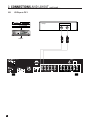
1
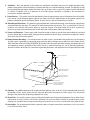
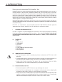
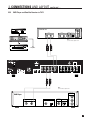
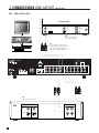
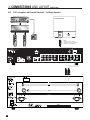
TLP 1
OPERATING MANUAL
w w w. a n t h e m AV. c o m
™
SAFETY PRECAUTIONS
READ THIS SECTION CAREFULLY BEFORE PROCEEDING!
WARNING
RISK OF ELECTRIC SHOCK
DO NOT OPEN
WARNING: TO REDUCE THE RISK OF ELECTRIC SHOCK,
DO NOT REMOVE COVER (OR BACK). NO USERSERVICEABLE PARTS INSIDE. REFER SERVICING TO
QUALIFIED SERVICE PERSONNEL.
The lightning flash with arrowpoint within an equilateral triangle
warns of the presence of uninsulated “dangerous voltage” within
the product’s enclosure that may be of sufficient magnitude to
constitute a risk of electric shock to persons.
The exclamation point within an equilateral triangle warns users
of the presence of important operating and maintenance (servicing)
instructions in the literature accompanying the appliance.
WARNING: TO REDUCE THE RISK OF FIRE OR ELECTRIC SHOCK, DO NOT EXPOSE THIS PRODUCT TO RAIN OR MOISTURE
AND OBJECTS FILLED WITH LIQUIDS, SUCH AS VASES, SHOULD NOT BE PLACED ON THIS PRODUCT.
CAUTION: TO PREVENT ELECTRIC SHOCK, MATCH WIDE BLADE OF PLUG TO WIDE SLOT, FULLY INSERT.
CAUTION: FOR CONTINUED PROTECTION AGAINST RISK OF FIRE, REPLACE THE FUSE ONLY WITH THE SAME AMPERAGE
AND VOLTAGE TYPE. REFER REPLACEMENT TO QUALIFIED SERVICE PERSONNEL.
WARNING: UNIT MAY BECOME HOT. ALWAYS PROVIDE ADEQUATE VENTILATION TO ALLOW FOR COOLING. DO NOT
PLACE NEAR A HEAT SOURCE, OR IN SPACES THAT CAN RESTRICT VENTILATION.
IMPORTANT SAFETY INSTRUCTIONS
1. Read Instructions – All the safety and operating instructions should be read before the product is operated.
2. Retain Instructions – The safety and operating instructions should be retained for future reference.
3. Heed Warnings – All warnings on the product and in the operating instructions should be adhered to.
4. Follow Instructions – All operating and use instructions should be followed.
5. Cleaning – Unplug this product from the wall outlet before cleaning. Do not use liquid cleaners or aerosol cleaners. Use
a damp, soft cloth for cleaning.
6. Water and Moisture – Do not use this product near water – for example, near a bath tub, wash bowl, kitchen sink, or
laundry tub; in a wet basement; or near a swimming pool; and the like.
7. Accessories – Do not place this product on an unstable cart, stand, tripod, bracket, or table. The product may fall,
causing serious injury to a child or adult, and serious damage to the product. Use only with a cart, stand, tripod, bracket,
or table recommended by the manufacturer, or sold with the product. Any mounting of the product should follow
manufacturer’s instructions, and should use a mounting accessory recommended by the manufacturer.
8. Ventilation – Slots and openings in the cabinet are provided for ventilation and to ensure reliable operation of the
product and to protect it from overheating, and these openings must not be blocked or covered. The openings should
never be blocked by placing the product on a bed, sofa, rug, or other similar surface. This product should not be placed
in a built-in installation such as a bookcase or rack unless proper ventilation is provided or the manufacturer’s
instructions have been adhered to.
9. Power Sources – This product should be operated only from the type of power source indicated on the marking label.
If you are not sure of the type of power supply to your home, consult your product dealer or local power company. For
products intended to operate from battery power, or other sources, refer to the operating instructions.
10. Grounding and Polarization – This product may be equipped with a polarized alternating-current line plug (a plug having
one blade wider than the other). This plug will fit into the power outlet only one way. This is a safety feature. If you are
unable to insert the plug fully into the outlet, try reversing the plug. If the plug should still fail to fit, contact your
electrician to replace your obsolete outlet. Do not defeat the safety purpose of the polarized plug.
11. Power-cord Protection – Power-supply cords should be routed so that they are not likely to be walked on or pinched
by items placed upon or against them, paying particular attention to cords at plugs, convenience receptacles, and the
point where they exit from the product.
12. Outdoor Antenna Grounding – If an outside antenna or cable system is connected to the product, be sure the antenna
or cable system is grounded so as to provide some protection against voltage surges and built-up static charges. Article
810 of the National Electrical Code, ANSI/NFPA 70, provides information with regard to the proper grounding of the mast
and supporting structure, grounding of the lead-in wire to an antenna-discharge unit, size of grounding conductors,
location of antenna-discharge unit, connection to grounding electrodes, and requirements for the grounding electrode.
Antenna Lead-In Wire
Ground Clamp
Antenna-Discharge Unit
(NEC Section 810-20)
Electrical Service
Equiptment
Grounding Conductors
(NEC Section 810-21)
Ground Clamps
S2898A
NEC-National Electrical Code
Power Service Grounding
Electronic System
(NEC ART 250. Part H)
13. Lightning – For added protection for this product during a lightning storm, or when it is left unattended and unused for
long periods of time, unplug it from the wall outlet and disconnect the antenna or cable systems. This will prevent
damage to the product due to lightning and power-line surges.
14. Power Lines – An outside antenna system should not be located in the vicinity of overhead power lines or other electric
light or power circuits, or where it can fall into such power lines or circuits. When installing an outside antenna system,
extreme care should be taken to keep from touching such power lines or circuits as contact with them might be fatal.
15. Overloading – Do not overload wall outlets, extension cords, or integral convenience receptacles as this can result in
a risk of fire or electric shock.
16. Object and Liquid Entry – Never push objects of any kind through openings as they may touch dangerous voltage points
or short-out parts that could result in a fire or electric shock. Do not expose this product to dripping or splashing and
ensure that no objects filled with liquids, such as vases, are placed on the product.
17. Servicing – Do not attempt to service this product yourself, as opening or removing covers may expose you to
dangerous voltage or other hazards. Refer all servicing to qualified service personnel.
18. Damage Requiring Service – Unplug this product from the wall outlet and refer servicing to qualified personnel under
the following conditions:
• When power-supply cord or plug is damaged.
• If liquid has been spilled, or objects have fallen into the product.
• If the product has been exposed to rain or water.
• If the product does not operate normally by following the operating instructions. Adjust only those controls that are
covered by the operating instructions as an improper adjustment of other controls may result in damage and will require
extensive work by a qualified technician to restore the product to its normal operation.
• If the product has been dropped or damaged in any way.
• If the product exhibits a distinct change in performance – this indicates a need for service.
19. Replacement Parts – When replacement parts are required, be sure the technician has used replacement parts
specified by the manufacturer or have the same characteristics as the original part. Unauthorized substitutions may
result in fire, electric shock, or other hazards.
20. Safety Check – Upon completion of any service or repairs to this product, ask the service technician to perform safety
checks to determine that the product is in proper operating condition.
21. Heat – The product should be situated away from heat sources such as radiators, heat registers, stoves, or other
products (including amplifiers) that produce heat.
RECYCLING AND REUSE GUIDELINES (Europe)
In accordance with the European Union WEEE (Waste Electrical and Electronic Equipment) directive effective
August 13, 2005, we would like to notify you that this product may contain regulated materials which, upon disposal,
require special reuse and recycling processing. For this reason Paradigm Electronics Inc. (the manufacturer of
Paradigm speakers and Anthem electronic products) has arranged with its distributors in European Union member
nations to collect and recycle this product at no cost to you. To find your local distributor please contact the dealer
from whom you purchased this product or go to our website at www.paradigm.com.
Please note that only the product falls under the WEEE directive. When disposing of packaging and other shipping
material we encourage you to recycle through the normal channels.
Anthem, Sonic Frontiers, and Paradigm are trademarks or registered trademarks of Paradigm Electronics Inc.
Copyright Paradigm Electronics Inc. All rights reserved. The information contained herein may not be reproduced in whole
or in part without our express written permission. We reserve the right to change specifications and/or features without
notice as design improvements are incorporated.
TABLE of CONTENTS
SECTION
PAGE
1. INTRODUCTION
1
1
Receiving and Unpacking the TLP 1 . . . . . . . . . . . . . . . . . . . . . . . . . . . . . . . . . . . . . . . . . . . . . . . . . . . . . . 1
1.1
Packing List
1
1.2 Important Safety Information . . . . . . . . . . . . . . . . . . . . . . . . . . . . . . . . . . . . . . . . . . . . . . . . . . . . . . . . . . . . 1
1.2.1 Before Operating Your TLP 1
1
1.2.2 Supply Power Requirements
2
1.2.3 In-Use Notices
2
1.3 Packing Materials . . . . . . . . . . . . . . . . . . . . . . . . . . . . . . . . . . . . . . . . . . . . . . . . . . . . . . . . . . . . . . . . . . . . . . 2
2. CONNECTIONS AND LAYOUT
3
2.1 Quick Start Guide . . . . . . . . . . . . . . . . . . . . . . . . . . . . . . . . . . . . . . . . . . . . . . . . . . . . . . . . . . . . . . . . . . . . . . 3
2.2 Front and Rear Panel Layout . . . . . . . . . . . . . . . . . . . . . . . . . . . . . . . . . . . . . . . . . . . . . . . . . . . . . . . . . . . . 4
2.2.1 Front Panel Display
5
2.3 Connection Examples
2.3.1 CD Player to TLP 1
2.3.2 DVD Player and Satellite Receiver to TLP 1
2.3.3 VCR and TV to TLP 1
2.3.4 TLP 1 to Amplifier and Powered Subwoofer – Small Speakers
2.3.5 TLP 1 to Amplifier and Powered Subwoofer – Full Range Speakers
6
7
8
9
10
2.4 Remote Control Layout . . . . . . . . . . . . . . . . . . . . . . . . . . . . . . . . . . . . . . . . . . . . . . . . . . . . . . . . . . . . . . . . 11
2.5 Connecting Power to the TLP 1 . . . . . . . . . . . . . . . . . . . . . . . . . . . . . . . . . . . . . . . . . . . . . . . . . . . . . . . . 12
2.6 Audio Inputs . . . . . . . . . . . . . . . . . . . . . . . . . . . . . . . . . . . . . . . . . . . . . . . . . . . . . . . . . . . . . . . . . . . . . . . . . 12
2.7 Audio Outputs . . . . . . . . . . . . . . . . . . . . . . . . . . . . . . . . . . . . . . . . . . . . . . . . . . . . . . . . . . . . . . . . . . . . . . . . 12
2.8 FM•AM Antennas . . . . . . . . . . . . . . . . . . . . . . . . . . . . . . . . . . . . . . . . . . . . . . . . . . . . . . . . . . . . . . . . . . . . 13
2.9 Relay Trigger . . . . . . . . . . . . . . . . . . . . . . . . . . . . . . . . . . . . . . . . . . . . . . . . . . . . . . . . . . . . . . . . . . . . . . . . 13
2.10 Infra Red Receiver . . . . . . . . . . . . . . . . . . . . . . . . . . . . . . . . . . . . . . . . . . . . . . . . . . . . . . . . . . . . . . . . . . . . 13
3. FRONT PANEL OPERATION
14
3.1 Power On/Off . . . . . . . . . . . . . . . . . . . . . . . . . . . . . . . . . . . . . . . . . . . . . . . . . . . . . . . . . . . . . . . . . . . . . . . . . 14
3.2 Master Control Knob . . . . . . . . . . . . . . . . . . . . . . . . . . . . . . . . . . . . . . . . . . . . . . . . . . . . . . . . . . . . . . . . . . . 14
3.3 Source Selection . . . . . . . . . . . . . . . . . . . . . . . . . . . . . . . . . . . . . . . . . . . . . . . . . . . . . . . . . . . . . . . . . . . . . 14
3.3.1 FM•AM Tuner
14
3.4 Bass / Treble / Balance . . . . . . . . . . . . . . . . . . . . . . . . . . . . . . . . . . . . . . . . . . . . . . . . . . . . . . . . . . . . . . . . 15
3.5 Contour. . . . . . . . . . . . . . . . . . . . . . . . . . . . . . . . . . . . . . . . . . . . . . . . . . . . . . . . . . . . . . . . . . . . . . . . . . . . . . . 15
3.6 Display Brightness . . . . . . . . . . . . . . . . . . . . . . . . . . . . . . . . . . . . . . . . . . . . . . . . . . . . . . . . . . . . . . . . . . . . 15
4. REMOTE CONTROL OPERATION
16
4.1 Powering the TLP 1 ON and OFF . . . . . . . . . . . . . . . . . . . . . . . . . . . . . . . . . . . . . . . . . . . . . . . . . . . . . . . . 16
4.2 Direct FM•AM Station Entry . . . . . . . . . . . . . . . . . . . . . . . . . . . . . . . . . . . . . . . . . . . . . . . . . . . . . . . . . . . 16
4.3 Controlling Other Components . . . . . . . . . . . . . . . . . . . . . . . . . . . . . . . . . . . . . . . . . . . . . . . . . . . . . . . . . . 17
4.3.1 Entering Manufacturer’s Codes
17
4.3.2 Searching For a Code
17
4.3.3 Volume Lock
17
4.4 Teaching the TLP 1 Remote Control to Universal Learning Remotes . . . . . . . . . . . . . . . . . . . . . . . . . 18
Appendix A – Preset Memory Codes
19
Specifications
21
Warranty
23
Big Pictures of Front and Rear Panels
Inside Back Cover
1. INTRODUCTION
Thank you for purchasing the Anthem TLP 1 Preamplifier • Tuner.
Anthem Electronics has been manufacturing high-quality, high-end audio equipment for over a decade. In
that time, Anthem has built an enviable reputation for products that can recreate the passion a music lover
experiences when attending a live musical performance, or the thrilling sound a movie buff experiences in
the very best movie theaters. Anthem equipment allows audiophiles to almost “be there” each and every
time they sit and enjoy music or home theater in the comfort of their home. Anthem provides all this with the
highest level of craftsmanship, sophisticated circuit designs, superior quality parts and materials, modern
intuitive ergonomics, and stylish industrial design.
Although Anthem products sound great “right out of the carton”, they will sound even better after they are
thermally stabilized. We therefore recommend that you operate this product for a period of time before doing
any critical listening.
The TLP 1 is a state-of-the-art stereo preamplifier with built-in FM • AM Tuner, Record output with
independent input selection, and built-in crossover with high-pass and low-pass outputs.
1
RECEIVING AND UNPACKING THE TLP 1
The TLP 1 is shipped in a reinforced shipping box. Check that you have received everything in the Packing
List below and report any discrepancies to your dealer as soon as possible. Keep the invoice that you
received from your authorized Anthem dealer at time of purchase – without it, service cannot be given
under warranty.
1.1
PACKING LIST
•
•
•
•
•
•
•
•
1.2
TLP 1
Remote Control
2 ‘AA’ Batteries
Power Cord
FM Antenna
75-ohm to 300-ohm FM Antenna Adapter
AM Loop Antenna
Operating Manual
IMPORTANT SAFETY INSTRUCTIONS
• The Front Panel power switch is secondary only; it does not disconnect the TLP 1 from the AC
power line.
• Failing to comply with any safety instruction, precaution, or warning in this Operating Manual is in
direct violation of the standards of design, manufacture, and intended use of the product.
• Anthem, Sonic Frontiers International, our agents, and any related party assume no liability
whatsoever for the user’s failure to comply with any or all of these requirements.
1.2.1 BEFORE OPERATING YOUR TLP 1
• Do not connect power to the TLP 1 if there are signs of damage to its exterior.
• Do not install in an unstable location or in an equipment rack that may be at risk of collapsing. Do
not mount to a wall or from a ceiling, or in any way that poses risk of injury.
• Allow at least 6 inches of unobstructed air space above the ventilation slots in the top cover of the
amplifier. Do not block any ventilation openings. Do not obstruct bottom vents by removing the
rubber feet or operating the amplifier directly on a carpet, sofa, or similar surface.
1
1. INTRODUCTION continued …
1.2.2 SUPPLY POWER REQUIREMENTS
The TLP 1 operates from a single phase AC power source that supplies between 105V and 130V at a
frequency of 60 Hz. It cannot be changed from 120V to 240V operation.
1.2.3 IN-USE NOTICES
• Use only the power supply cord with double insulation as supplied.
• Disconnect the amplifier’s power cord before connecting or disconnecting any components.
• Do not remove the top cover.
• Do not alter or modify the amplifier in any way.
• Rail fuses are not a user serviceable item.
1.3
PACKING MATERIALS
Retain the shipping box and all packing material. They are custom designed to prevent shipping damage from
occurring. Do not ship or transport the TLP 1 in anything other than the original box and packing material.
2
2. CONNECTIONS AND LAYOUT
With your TLP 1 in front of you, browse through the illustrations in this section to see several quick system
hookup options. It’s as simple as following the lines in the connection diagrams to and from each component.
2.1
QUICK START GUIDE – Before you start, make sure all components are unplugged.
To connect a CD player, DVD player, TV, VCR, amplifier, and powered subwoofer to the TLP 1:
• CD Player to TLP 1 – see diagram in section 2.3.1
Connect the L/R audio output of the CD player to Analog Audio-In/CD on the TLP 1.
• DVD Player to TLP 1 – see diagram in section 2.3.2
Connect the L/R audio output of the DVD player to Analog Audio-In/DVD on the TLP 1.
• Satellite Receiver to TLP 1 – see diagram in section 2.3.2
Connect the L/R audio output of the receiver to Analog Audio-In/SAT•AUX on the TLP 1.
• TV to TLP 1 – see diagram in section 2.3.3
Connect the L/R audio output of the TV to Analog Audio-In/SAT•AUX on the TLP 1. If you are
using a satellite receiver and your TV does not have audio inputs and outputs, connect the
satellite receiver directly to Analog Audio-In/SAT•AUX on the TLP 1.
• VCR to TLP 1 – see diagram in section 2.3.3
Connect the L/R audio output of the VCR to Analog Audio-In/VCR on the TLP 1.
To Record: Connect Analog Audio-Out/RECORD on the TLP 1 to the L/R audio input of the VCR.
• TLP 1 to Amplifier – see diagrams in sections 2.3.4 and 2.3.5
From the TLP 1, connect Left and Right outputs to the inputs of the power amplifier. Use
FULL RANGE if using full-range speakers either with or without a subwoofer, and HIGH
PASS if using speakers with limited low-frequency response along with a subwoofer.
Follow the amplifier manufacturer’s instructions for connecting the speakers.
• TLP 1 to Powered Subwoofer – see diagrams in sections 2.3.4 and 2.3.5
From the TLP 1, connect Analog Audio-Out/SUBWOOFER to the subwoofer’s line/low level
input. Use FULL RANGE if the subwoofer has a built-in crossover, and LOW PASS if the
subwoofer’s crossover is bypassed or if the subwoofer doesn’t have a crossover.
Reconnect the power to all components and turn them on. To turn on the TLP 1 press the POWER button on
the front panel.
To Listen to a CD:
• Press CD Source on the front panel of the TLP 1.
• Place a CD into the CD player and press play. You should hear music coming from your speakers.
Use the TLP 1 Master Control Knob on the front panel to adjust volume.
To Watch a DVD:
• Press DVD Source on the front panel of the TLP 1.
• Select the TV input that corresponds to the one that the DVD player’s video output is plugged into.
• Place a DVD into the DVD player and press play. You should see the picture on your TV and hear
sound from your speakers. Use the TLP 1 Master Control Knob on the front panel to adjust volume.
3
2. CONNECTIONS AND LAYOUT continued …
2.2
FRONT AND REAR PANEL LAYOUTS
1
15
14
13
2
12
3
11
4
5
10
9
6
8
7
1 – FM•AM Preset selection
7 – Power On / Stand-By
2 – Display
8 – Contour On/Off
3 – FM•AM Seek
9 – Mute
4 – FM•AM Tune
10 – Bass / Treble settings
5 – FM Stereo / Hi Blend / Mono
11 – Front Panel Remote Control IR Sensor
6 – Master Control Knob:
12 – Balance / Display Brightness setting
• Volume
13 – Headphone Jack
• Tune for FM•AM
14 – Record Path selection
• Setting Adjustment for Bass / Treble / Balance;
Display Brightness; Input Level
15 – Source selection
2
1
12
11
10
3
8
9
7
6
5
1 – RS-232 port (for custom installation)*
7 – 2 Subwoofer Outputs (Low Pass)
2 – FM Antenna Input
8 – 2 Line Level Outputs (Record, Zone 2 – L/R jacks)
3 – AM Antenna Input
9 – 5 Inputs (L/R jacks)
4 – Full Range Output (L/R jacks)
10 – Relay Trigger Output (3.5 mm mono jack)
5 – High Pass Output (L/R jacks)
11 – Infra Red Input (3.5 mm mono jack)
6 – 2 Subwoofer Outputs (Full Range)
12 – Power Cord Connection
4
*Custom Installers: RS-232 port is on newer production TLP 1s only. Command set is available at www.anthemAV.com.
4
2. CONNECTIONS AND LAYOUT continued …
2.2.1 FRONT PANEL DISPLAY
Main Display Example:
2
1
1 –
Source selection.
2 –
Volume setting. When muted, “Muted” flashes instead of the current volume setting.
FM•AM Display Example:
1
2
3
1 –
Source+Bank. The tuner has three FM banks (FM1, FM2, and FM3) and one AM bank. The number
after the selected bank is the preset station.
2 –
FM mode. Displays “St” when in stereo, “HB” when Hi-Blend is selected, or “Mn” when in mono or
mono is selected.
3 –
Currently tuned FM•AM frequency to the nearest 0.1 MHz for FM and to nearest 10 kHz for AM.
Record Display Example:
1
2
1 –
Source selection.
2 –
Record path indication. Note that the selection time lasts approximately 3 seconds, after which the
normal display returns.
5
2. CONNECTIONS AND LAYOUT continued …
2.3.1
CD Player to TLP 1
CD Player
Track 1
CD Player
EJECT
Amplifier
6
Audio Out
R
L
2. CONNECTIONS AND LAYOUT continued …
2.3.2
DVD Player and Satellite Receiver to TLP 1
SATELLITE
Component
Video Out
Satellite Receiver
Y
Digital Out
Audio Out
R
L
RCA
Composite
Video Out
S-Video Out
Toslink
Pb
Pr
Note:
Connect video output to TV.
DVD
Amplifier
Note:
Connect video output to TV.
Component
Video Out
DVD Player
Y
Digital Out
Audio Out
R
L
RCA
Toslink
Composite
Video Out
S-Video Out
Pb
Pr
7
2. CONNECTIONS AND LAYOUT continued …
2.3.3
VCR and TV to TLP 1
Rear Panel of TV
Audio
Out
Y
CATV
In
Composite
Video In
L
Vari
Pb
Fixed
S-Video In
R
Pr
Note:
Connect video output from
source components to TV.
Note:
If using a satellite receiver and a TV
monitor that does not have audio inputs
and outputs, connect satellite receiver’s
audio outputs directly to SAT•AUX.
VCR
EJECT
Note:
Connect video output to TV.
VCR
Composite
L
S-Video
R
OUT
8
Audio
Video
IN
OUT
IN
Component
Video In
2. CONNECTIONS AND LAYOUT continued …
TLP 1 to Amplifier and Powered Subwoofer – Small Speakers
Powered Subwoofer
Input
WE
PO
2.3.4
RCA
R
Level
Note:
If subwoofer does not have a
built-in crossover, use Low Pass
output instead of Full Range.
P V A
RIG H T
IN P U T
2
SERIAL NO.:
LEF T
IN P U T
9
2. CONNECTIONS AND LAYOUT continued …
2.3.5
TLP 1 to Amplifier and Powered Subwoofer – Full Range Speakers
Powered Subwoofer
PO
WE
R
Input
RCA
Level
Note:
If subwoofer does not have a
built-in crossover, use Low Pass
output instead of Full Range.
M C A
VA
10
20
WARNING
RISK OF HAZARDOUS ENERGY! MAKE PROPER SPEAKER CONNECTIONS. SEE OPERATING MANUAL BEFORE USING.
2. CONNECTIONS AND LAYOUT continued …
2.4
REMOTE CONTROL LAYOUT
1
2
1 – IR Transmitter (front face)
2 – Transmission Indicator LED (red)
3 – TLP 1 Power ON
Power ON/OFF for other components (see #4)
Note: This does not turn the TLP 1 off (see #21)
4 – Control Mode selection
5 – FM•AM Preset selection (6)
6 – FM•AM Preset Station Up
7 – FM•AM Preset Station Down
8 – Selects Tone Bypass
9 – Selects Stereo / Hi Blend / Mono for FM•AM
10 – RECORD Path selection
11 – Contour On/Off
12 – Display Brightness
13 – Source selection
14 – Bass setting
15 – Treble setting
16 – Balance setting
17 –
• Tune for FM•AM
• Setting Adjustment Bass / Treble
• Seek for FM•AM
• Setting Adjustment for Balance
18
19
20
21
22
23
–
–
–
–
–
–
FM•AM Direct Entry
Volume Down
Volume Up
TLP 1 Power OFF
Mute
Setup (for customization of remote)
23
3
4
5
22
21
20
6
19
7
18
17
16
15
14
8
9
10
13
12
11
11
2. CONNECTIONS AND LAYOUT continued …
2.5
CONNECTING POWER TO THE TLP 1
Connect the power cord to the back of the TLP 1 and then to an AC outlet. If excessive hum or buzz is heard
through the speakers during operation, remove the cord from the back of the TLP 1 and re-insert it after
turning the connector upside down.
2.6
AUDIO INPUTS
Audio connections are made through interconnect cables – typically white or black for the Left channel and
red for the Right channel. The audio output connectors on tape recorders, VCRs, and CD players are normally
color coded in this same manner – connect them to the appropriate inputs on the TLP 1:
2.7
AUDIO OUTPUTS
Any of the outputs shown below can be used simultaneously:
Fixed Outputs:
These provide a fixed line-level output for connection to a tape recorder’s or VCR’s audio record inputs,
and/or to an integrated amplifier or receiver that is used for another room (Zone 2) so sources connected to
the TLP 1 can be directed to that remote location. The volume control does not affect this output level.
Subwoofer:
Intended to be used with a powered subwoofer or subwoofer amplifier, each of the four jacks provides a
mono signal of the left and right channels combined. Up to two subwoofers can be connected in either of the
following configurations: Low Pass, which contains only low bass, or Full Range, which is unfiltered.
• Use Full Range if the subwoofer has a built-in crossover.
• Use Low Pass if the subwoofer’s crossover is bypassed or if there is no crossover in the subwoofer
or subwoofer amplifier.
Main:
The High Pass output reduces low bass which makes it ideal when using smaller speakers that are unable
to reproduce deeper bass or bass at full output levels. The use of a powered subwoofer is strongly
recommended with this setup. The unfiltered Full Range output is the ‘normal’ full bandwidth audio output.
• Use Full Range if using full bandwidth speakers, either with or without a subwoofer.
• Use High Pass if using smaller speakers and a subwoofer.
12
2. CONNECTIONS AND LAYOUT continued …
Headphone:
When a headphone plug is inserted into the headphone jack on the front panel, all audio
outputs on the rear panel are muted.
2.8
FM•AM ANTENNAS
To connect the FM antenna, first connect the two antenna wires to the
screw terminals of the 75-ohm to 300-ohm adapter. Then connect the
adapter to the FM ANTENNA connector on the TLP 1. If your local cable
company provides FM service, connect the cable directly to the TLP 1
instead of using the antenna.
75-ohm to 300-ohm adapter
To connect the AM loop antenna, press the spring-loaded tabs of the AM
ANTENNA connector, insert the bare ends of the wire from the loop antenna
and release the tabs.
Once the antennas are connected, move each of them around until best
reception is found. For the FM antenna, this will usually be in a “T” formation.
2.9
RELAY TRIGGER
If your other components, such as the power amplifier, have a trigger input, you can
automatically turn them on and off simultaneously with the TLP 1. Connect the RELAY
TRIGGER trigger output from the TLP 1 to the trigger input of your power amplifier, TV
monitor, etc., using a cable with 3.5mm mono mini plugs.
2.10
INFRA RED RECEIVER
An external IR repeater allows the Remote Control to be used from other locations in your
home, for example Zone 2. Once a repeater is wired to a selected room, connect it to the
I.R. RECEIVER input.
13
3. FRONT PANEL OPERATION
3.1
POWER ON/OFF
When turned on, the TLP 1 will have all of the same settings it had when it was last turned
off, except for Volume, which comes on at -30 dB.
3.2
MASTER CONTROL KNOB
Besides being a Volume Control, the MASTER CONTROL KNOB also operates other functions, including
adjustment of Bass / Treble / Balance, FM•AM tuning, Input Level, and Display Brightness selection.
Mute:
When MUTE is pressed, the audio output is silenced. Press MUTE again, or rotate the Master
Control Knob to adjust the volume, and sound will return.
3.3
SOURCE SELECTION
The TLP 1 accommodates up to five external sources plus the built-in FM•AM stereo tuner. The main path
selection is completely independent from the record path selection.
Main Path:
To make a source selection, simply press the corresponding button.
Record Path:
To make a selection for the Record outputs, press Record, then
press a source button within 3 seconds – the red indicator will
remain lit for the duration of the selection period.
Adjust Input Levels:
You can match main path input levels to each other to prevent large changes in volume as you change from
one source to another. Press and hold the source button of the input you want to adjust, and when ‘Lvl +0.0’
appears on the display, adjust using the Master Control Knob before the main display returns.
Before making input level adjustments, have all connected source components playing similar music
material. Also, make sure that all four tuner banks are tuned to a station (see below). Then, as you switch
through each source, you will hear that component play. This allows for easy comparative level adjustments.
Note: The selected tuner bank immediately changes when pressing FM•AM. To adjust AM input level,
select FM-3 first, then press and hold FM•AM and the band will automatically change to AM.
3.3.1 FM•AM TUNER
The TLP 1 has a built-in FM • AM tuner. The station that is selected for the main outputs is automatically
shared when FM•AM is selected for Record.
Manual Tuning:
Select the desired bank by pressing FM•AM, then press TUNE and rotate the Master Control
Knob to find a station.
Automatic Tuning:
To automatically find the next station, press SEEK or SEEK. To scan and listen to all
available radio stations for a few seconds at a time, press and hold SEEK or SEEK for
about a second. The ‘ Seek’ or ‘ Seek’ indicator on the display will change to ‘’ or
‘’ to indicate that the tuner is scanning. To stop scanning, press the same SEEK button
that was used to initiate scanning.
14
3. FRONT PANEL OPERATION continued …
Presets:
18 FM and 6 AM stations can be stored in the TLP 1. The
presets are divided into four banks of six. By repeatedly
pressing FM • AM, the display will show that you are cycling
through ‘FM1’, ‘FM2’, ‘FM3’, ‘AM’. Once you have selected the
desired bank, you can store the currently tuned radio station by pressing and holding one of the six preset
keys (1 through 6) for about a second. You can even do this while scanning for stations. The lower line of the
display briefly flashes once the station is stored. To recall a preset, select the bank that it is in, then press
the respective preset key.
ST / HB / Mn:
If FM reception is weak, switching a station out of stereo can reduce or eliminate unwanted
hiss and noise. Press ST / HB / Mn repeatedly to cycle through Stereo, Hi-Blend, or Mono.
Hi-Blend offers an alternative to Mono, offering decreased noise without the complete loss
of stereo – it decreases noise by reducing some stereo separation at higher frequencies.
When storing a station to a preset, your selected preference of Stereo, Hi-Blend, or Mono will also be stored.
3.4
BASS / TREBLE / BALANCE
To change Bass, Treble, or Balance, press BASS, TREBLE, or BALANCE • DISPLAY,
then adjust using the Master Control Knob.
Bass and Treble settings are stored in memory by source – for example, you may
want to set treble for AM to +6, FM to -1 and Tape to +1. The TLP 1 memorizes bass
and treble settings for each source independantly. This allows you to switch
between sources without having to constantly make Bass or Treble adjustments.
Tone Bypass:
Pressing BYPASS disables Bass/Treble adjustments, as well as defeating the Contour feature if it has been
engaged. To enable Bass/Treble again, press either BASS or TREBLE.
3.5
CONTOUR
When listening at low levels, our hearing sensitivity to bass and treble frequencies
decreases. When engaged, the Contour function of the TLP 1 compensates by adding bass
and treble according to volume setting and a psychoacoustically modeled compensation
curve. It begins to take effect when the volume setting is around -20 dB. Bass and treble
added relative to the overall signal gradually increases as the volume is lowered.
3.6
DISPLAY BRIGHTNESS
The intensity of the Front Panel display and indicators can be changed. Press BALANCE•DISPLAY twice and
then use the Master Control Knob to select High, Medium, or Low.
15
4. REMOTE CONTROL OPERATION
The TLP 1 Universal Remote Control has all of the
same functions as the front panel buttons and is
operated in a similar way, but there are some
differences. Please take the time to read this
section to fully understand all the functions of the
TLP 1 Remote Control.
IR Transmitter
Power ON
Transmission Indicatior
Setup Mode
Control Mode
The keys labeled in this illustration show those that
have a different method of operation from their
front panel counterparts. Those shown in bold
italics indicate keys that are unique to the Remote
Control and not found on the Front Panel. For a
detailed layout diagram see section 2.4.
Before we get started, we have to give the remote
a little attitude adjustment – set the ‘personality’ to
TLP by pressing TLP Control Mode key near the top
of the remote.
Note: The Control Mode keys do not transmit
any commands. They only determine where
subsequent commands are sent. For example,
if TV is selected followed by CH+, the channel
changes on your TV while the TLP 1 and all
other components remain unaffected (see
section 4.3.1 and Appendix A to set up reset
memory codes).
FM•AM Presets
FM•AM Presets
UP / DOWN
TLP 1 Power OFF
FM•AM Direct Entry
• FM•AM Seek / Tune
• Bass/Treble / Balance
Adjustments
• Input Level Adjustment
RECORD Path
Did we forget to mention the batteries? They go in
by taking off the rear cover – remember polarity.
Down the road, if the LED blinks twice each time a
command is sent and the TLP 1 doesn’t respond, it’s
an indication that the batteries need replacement.
4.1
Source Selection
Display Brightness
POWERING THE TLP 1 ON AND OFF
Separate power commands are a requirement in
custom multi-zone installations, and for this reason
two different keys are used to turn the TLP 1 ON
and OFF.
The
power key in the top right corner turns the TLP 1 Power ON. The red TLP OFF key in towards the
middle turns the TLP 1 Power OFF.
The TLP 1 is turned ON and OFF as follows:
• ON: Press
.
• OFF: Press TLP OFF.
4.2
DIRECT FM•AM STATION ENTRY (Remote Control Only)
When using the FM•AM Tuner, the station frequency can be entered as a four-digit number. For example, to
tune into 98.3 FM, press and hold SELECT until the display shows “<blank>0.0” in the lower left corner, then
press 0, 9, 8, 3.
16
4. REMOTE CONTROL OPERATION continued …
4.3
CONTROLLING OTHER COMPONENTS
The TLP 1 Remote Control can be set up to control your TV, DVD player or VCR, and satellite receiver or cable
converter. It contains a set of codes for models from many different manufacturers, which can be entered to
virtually duplicate another remote control.
4.3.1 ENTERING PRESET MEMORY CODES
In Appendix A, at the back of this manual, you will find codes for programming the TLP 1 remote. To enter a
preset memory code:
1. Press the Component key (e.g. DVD).
2. Press and hold SETUP until the LED flashes twice.
3. Enter the four-digit code from Appendix A. The LED should blink twice.
VCR and Laser Disc player codes can be programmed into the DVD key, and Cable Converter codes can
be programmed into the SAT key. A VCR code, for example, can not be programmed into the TV key.
4.3.2 SEARCHING FOR A CODE
If a code for your component is not listed in Appendix A, it may be buried under a different name, for example
if one DVD player manufacturer uses a mechanism from another manufacturer:
1. Turn the component on (e.g. DVD player).
2. Press the matching Component key (e.g. DVD).
3. Press and hold SETUP until the LED flashes twice.
4. Press 9, 9, 1.
5. Aim the remote towards the DVD player and alternate between pressing
and DVD.
6. Stop once the DVD player turns off. Immediately press and release SETUP to lock the code.
Note: There may be more than one manufacturer code that causes power to turn on/off on your
component – you may have to try this a few times before finding a code that controls all functions.
7. If, for future reference, you want to know what the code is, press and hold SETUP until the LED
flashes twice and then press 9, 9, 0, 1. Wait 3 seconds and count the number of flashes. The number
of flashes represent the first digit (i.e. 3 flashes = 3, no flash = 0). Next, press 2 for the second digit,
3 for the third digit, and 4 for the fourth digit, and count the number of flashes each time. Record this
code number in Appendix A for future reference.
4.3.3 VOLUME LOCK
After entering a code for your TV or satellite receiver, you may find it inconvenient to switch the Component
keys back and forth when you alternate between say, changing channels on your TV and adjusting volume
on the TLP 1. Not to worry, the Volume Lock feature takes care of this. When engaged, the volume keys adjust
TLP volume, regardless of which Component is selected. You can then leave your Component selection in TV
– you no longer have to press TLP first to adjust the volume of the TLP 1.
17
4. REMOTE CONTROL OPERATION continued …
In the following example, TLP volume is locked onto every Component selection except TV:
To Engage Volume Lock for TLP:
1. Press and hold SETUP until the LED flashes twice.
2. Press 9, 9, 3.
3. Press TLP.
At this point, the Volume and Mute keys now control the TLP 1, no matter which of the four Component
selections the Remote Control is in. However, since this may not be desirable, any individual Component
selection can be unlocked.
To Disengage Volume Lock for TV, and re-engage the TV Volume Control:
4. Press TV.
5. Press and hold SETUP until the LED flashes twice.
6. Press 9, 9, 3.
7. Press VOL .
The Volume and Mute keys now control the TLP 1 for every Component selection except for TV. You may
continue to unlock other Components one at a time. To unlock all Components at once and restore the default
setting, press VOL+ instead of VOL in step 7.
4.4
TEACHING THE TLP 1 REMOTE CONTROL TO UNIVERSAL LEARNING REMOTES
Some keys on the TLP 1 Remote, such as VOL+, VOL , and SELECT have press and hold commands as well
as regular press and release commands. The ‘press and hold’ command of a key is exactly the same as the
‘press and release’ command of that key, repeated as long as the key is held. It may be necessary to program
your aftermarket remote to loop or repeat a ‘press and release’ command to turn it into a ‘press and hold’
command. The methods of doing this vary with the model – contact the remote control manufacturer for
more information.
18
APPENDIX A – PRESET MEMORY CODES
VCR and Laser Disc player codes can be programmed into the DVD key, and Cable Converter codes can be programmed into the SAT key. To enter a code:
1.
2.
3.
Press the Component key (e.g. TV).
Press and hold SETUP until the LED flashes twice.
Enter the four-digit code. The LED should blink twice.
TVs:
AOC
Admiral
Aiko
Akai
Alaron
Allegro
Ambassador
Ampro
Anam
Audiovox
Aumark
Baysonic
Belcor
Bell & Howell
Bradford
Brockwood
Broksonic
CXC
Candle
Carnivale
Carver
Celebrity
Cineral
Citizen
Concerto
Contec
Craig
Crosley
Crown
Curtis Mathes
Daewoo
Daytron
Denon
Dumont
Dwin
Electroband
Emerson
Envision
Fisher
Fujitsu
Funai
Futuretech
GE
Gibralter
Go Video
GoldStar
Gradiente
Grunpy
Hallmark
Harley Davidson
Harman/Kardon
Harvard
Hitachi
Infinity
Inteq
JBL
JCB
JVC
KEC
KTV
Kenwood
LG
LXI
Logik
Luxman
MGA
0030, 0019
0093
0092
0030
0179
0720, 0774
0177
0751
0180
0451, 0180, 0092, 0623
0060
0180
0019
0154, 0016
0180
0019
0236, 0463
0180
0030, 0056
0030
0054
0000
0451, 0092
0060, 0030, 0056, 0039,
0092
0056
0180
0180
0054
0180, 0039
0047, 0054, 0154, 0051,
0451, 0093, 0060, 0030,
0145, 0056, 0016, 0039,
0166, 0466, 1147, 1347
0451, 0019, 0039, 0092,
0623, 0624
0019, 0039
0145
0017, 0019
0720, 0774
0000
0154, 0236, 0463, 0180,
0282, 0178, 0019, 0179,
0039, 0177, 0623, 0624
0030
0154
0179
0180, 0179, 0171
0180
0047, 0051, 0451, 0093,
0282, 0178, 0021, 0135,
1147, 1347
0017, 0030, 0019
0060
0030, 0178, 0019, 0056,
0039
0053, 0056
0180, 0179
0178
0179
0054
0180
0145, 0056, 0151
0054
0017
0054
0000
0053
0180
0180, 0030, 0039
0030, 0019
0056
0047, 0054, 0017, 0154,
0156, 0178, 1347
0016
0056
0150, 0030, 0178, 0019
MTC
Magnavox
Majestic
Marantz
Matsushita
Megatron
Memorex
Midland
Minutz
Mitsubishi
Motorola
Multitech
NAD
NEC
NTC
Nikko
Onwa
Optimus
Optonica
Orion
Panasonic
Penney
Philco
Philips
Pilot
Pioneer
Portland
Prism
Proscan
Proton
Pulsar
Quasar
RCA
Radio Shack
Realistic
Runco
SSS
Sampo
Samsung
Samsux
Sansei
Sansui
Sanyo
Scimitsu
Scotch
Scott
Sears
Semivox
Semp
Sharp
Shogun
Signature
Sony
Soundesign
Squareview
Starlite
Supreme
Sylvania
Symphonic
TMK
Tandy
0060, 0030, 0019, 0056
0054, 0030, 0179
0016
0054, 0030
0051, 0250
0178, 0145
0154, 0250, 0150, 0060,
0178, 0056, 0016
0047, 0017, 0051, 0039,
0135
0021
0093, 0150, 0178, 0019
0093
0180
0156, 0178, 0166
0030, 0019, 0056
0092
0047, 0017, 0154, 0156,
0030, 0178, 0092, 1347
0180
0154, 0250, 0166
0093, 0165
0236, 0463, 0179
0047, 0054, 0154, 0156,
0051, 0250, 0093, 0165,
0150, 0060, 0053, 0178,
0145, 1347
0047, 0156, 0051, 0060,
0030, 0178, 0021, 0019,
0056, 0039, 0135, 1347
0054, 0463, 0030, 0145,
0019
0054, 0017, 0000, 0021,
0019, 0039
0030, 0019, 0039
0166
0019, 0039, 0092
0051
0047, 0030, 1347
0178, 0466
0017, 0019
0051, 0250, 0165
0047, 0051, 0093, 0019,
0090, 0135, 1047, 1147,
1247, 1347
0047, 0154, 0165, 0180,
0030, 0178, 0019, 0056,
0039
0154, 0165, 0180, 0030,
0178, 0019, 0056, 0039
0017, 0030, 0603
0180, 0019
0030, 0039
0060, 0030, 0178, 0019,
0056, 0039
0039
0451
0463
0154
0019
0178
0236, 0180, 0178, 0019,
0179
0047, 0054, 0154, 0156,
0178, 0179, 0056, 0171
0180
0156
0093, 0165, 0039
0019
0016
0000
0180, 0178, 0179
0171
0180
0000
0054, 0030
0171
0178, 0056, 0177
0093
Technics
Technol Ace
Techwood
Teknika
Telefunken
Toshiba
Totevision
Universal
Vector Research
Victor
Vidikron
Vidtech
Wards
White Westinghouse
Yamaha
Zenith
0047, 0017, 0051, 0250,
1347
0179
0051, 0056
0054, 0180, 0150, 0060,
0019, 0179, 0056, 0016,
0039, 0092
0056
0154, 0156, 0060
0039
0021
0030
0053
0054
0178, 0019
0054, 0156, 0165, 0030,
0178, 0021, 0019, 0179,
0056, 0016, 0135
0623, 0624
0030, 0019
0017, 0016, 0092
VCRs:
Admiral
Adventura
Aiko
Aiwa
Akai
American High
Asha
Audiovox
Beaumark
Bell & Howell
Broksonic
CCE
Calix
Canon
Carver
Cineral
Citizen
Colt
Craig
Curtis Mathes
Cybernex
Daewoo
Denon
Dynatech
Electrohome
Electrophonic
Emerex
Emerson
Fisher
Fuji
Funai
GE
Garrard
Go Video
GoldStar
Gradiente
HI-Q
Harley Davidson
Harman/Kardon
Harwood
Headquarter
Hitachi
JVC
Jensen
KEC
KLH
Kenwood
Kodak
LXI
Lloyd’s
Logik
MEI
MGA
MGN Technology
0048
0000
0278
0037, 0000
0041
0035
0240
0037
0240
0104
0184, 0121, 0209, 0002
0072, 0278
0037
0035
0081
0278
0037, 0278
0072
0037, 0047, 0240, 0072,
0271
0060, 0035, 0041, 0162
0240
0045, 0278
0042
0000
0037
0037
0032
0037, 0184, 0000, 0121,
0043, 0209, 0002, 0278
0047, 0104
0035, 0033
0000
0060, 0035, 0048, 0240
0000
0526
0037, 0038
0000
0047
0000
0081, 0038
0072
0046
0000, 0042, 0041
0067, 0041
0041
0037, 0278
0072
0067, 0041, 0038, 0046
0035, 0037
0037
0000
0072
0035
0240, 0043
0240
19
APPENDIX A – PRESET MEMORY CODES continued …
MTC
Magnasonic
Magnavox
Magnin
Marantz
Marta
Matsushita
Memorex
Minolta
Mitsubishi
Motorola
Multitech
NAP
NEC
Nikko
Noblex
Olympus
Optimus
Orion
Panasonic
Penney
Pentax
Philco
Philips
Pilot
Pioneer
Profitronic
Proscan
Protec
Pulsar
Quarter
Quartz
Quasar
RCA
Radio Shack
Radix
Randex
Realistic
Runco
STS
Samsung
Sanky
Sansui
Sanyo
Scott
Sears
Semp
Sharp
Shintom
Shogun
Signature
Singer
Sony
Sylvania
Symphonic
TMK
Tatung
Teac
Technics
Teknika
Thomas
Toshiba
Totevision
Unitech
Vector
Vector Research
Video Concepts
Videosonic
Wards
White Westinghouse
XR-1000
Yamaha
Zenith
20
0240, 0000
0278
0035,0039, 0081, 0000,
0149
0240
0035, 0081, 0038
0037
0035,0162, 0454
0035, 0037, 0048, 0039,
0047, 0240, 0000, 0104,
0046, 1162, 1262
0042
0048, 0067, 0043
0035, 0048
0000,0072
0035, 0037, 0039, 0042,
0033
0104, 0067, 0041, 0038
0037
0240
0035
0037,0048, 0104, 0162,
0454,1062, 1162, 1262
0184, 0002
0035, 0162, 0225, 0454,
1162
0035, 0037, 0240, 0042,
0038
0042
0035, 0209
0035, 0081
0037
0067
0240
0060
0072
0039
0046
0046
0035,0162, 0454, 1162
0060,0035, 0048, 0240,
0042, 0149
0000
0037
0037
0035, 0037, 0048, 0047,
0000, 0104, 0046
0039
0042
0240, 0045
0048, 0039
0000, 0067, 0041, 0271
0047, 0240, 0104, 0046
0184, 0045, 0121, 0043
0035, 0037, 0047, 0000,
0042, 0104, 0046
0045
0048
0072
0240
0035
0072
0035, 0032, 0000, 0033
0035, 0081, 0000, 0043
0000
0240
0041
0000, 0041
0060, 0035, 0039, 0162
0035, 0037, 0000
0000
0045, 0043
0037, 0240
0240
0045
0038
0045
0240
0060, 0035, 0048, 0047,
0081, 0240, 0045, 0000,
0042, 0072, 0149
0278
0035, 0000, 0072
0041, 0038
0039, 0000, 0033
TV/VCR Combos:
American High
Brocksonic
Colt
Curtis Mathis
Daewoo
Emerson
Funai
GE
Hitachi
HQ
Lloyds
MGA
Magnavox
Magnin
Memorex
Mitsubishi
Orion
Panasonic
Penney
Quasar
RCA
Sansui
Sanyo
Sears
Sharp
Sony
Symphonic
Zenith
0035 (for TV use 0051)
0002, 0294
0072
0035 (for TV use 0051)
0278
0002, 0294, 0479
0000
0035 (for TV use 0051)
0060 (for TV use 0047)
0048 (for TV use 0093)
0240
0035 (for TV use 0051)
0000
0000
0000
0240
0081 (for TV use 0054)
0035 (for TV use 0051)
0000
0240
0037,
0162 (for TV use 0250)
0048 (for TV use 0093)
0002, 0294, 0479
0035 (for TV use 0051)
0162 (for TV use 0250)
0035 (for TV use 0051)
0240,
0162 (for TV use 0250)
0035 (for TV use 0051)
0162 (for TV use 0250)
0060 (for TV use 0047)
0035 (for TV use 0051)
0048 (for TV use 0093)
0000, 0479
0240
0000, 0037
0048 (for TV use 0093)
0032 (for TV use 0000)
0000
0000
Cable Converters:
ABC
Allegro
Archer
Bell & Howell
Century
Citizen
Comtronics
Contec
Eastern
Emerson
Everquest
Focus
Garrard
Gemini
General Instrument
GoldStar
Goodmind
Hamlin
Hitachi
Hytex
Jasco
Jerrold
Magnavox
Memorex
Movie Time
NAP
NSC
Oak
Optimus
Panasonic
Paragon
Philips
Pioneer
Popular Mechanics
Proscan
Pulsar
Quasar
0003, 0008, 0014, 0017,
0007, 0011, 0013
0153, 0315
0153, 0797
0014
0153
0153, 0315
0040
0019
0002
0797
0015, 0040
0400
0153
0015
0476, 0276, 0011, 0810
0144, 0040
0797
0020, 0259, 0009, 0034
0011
0007
0015, 0153, 0315
0003, 0012, 0476, 0276,
0014, 0015, 0011, 0810
0014
0000
0063
0007
0063
0019, 0007
0021
0000, 0107, 0021
0000
0153
0144, 0533
0400
0021
0000
0000
RCA
Radio Shack
Recoton
Regal
Regency
Rembrandt
Runco
SL Marx
Samsung
Scientific Atlanta
Signal
Signature
Sprucer
Starcom
Stargate
Starquest
TV86
Teleview
Tocom
Toshiba
Tusa
Unika
United Artists
Universal
Viewstar
Zenith
Zentek
0021
0015, 0315, 0797, 0883
0400
0020, 0259
0002
0011
0000
0040
0144, 0040
0008, 0477, 0017, 0877
0015, 0040
0011
0021
0003, 0015
0015,0040, 0797
0015
0063
0040
0012, 0013
0000
0015
0153
0007
0153,0191
0063
0008, 0000, 0015, 0525
0400
Satellite or DBS Receivers:
AlphaStar
Echostar
Expressvu
General Instrument
HTS
Hitachi
Hughes Net. Sys.
JVC
Jerrold
Magnavox
Memorex
Next Level
Panasonic
Philips
Primestar
Proscan
RCA
Radio Shack
Sony
Star Choice
Toshiba
Uniden
Zenith
0772
0775
0775
0627, 0361, 0869
0775
0819
0749
0775
0627, 0361
0724, 0722
0724
0869
0701
0724, 0722
0627, 0361
0566
0566, 0143, 0855
0566, 0869
0639
0869
0790
0724, 0722
0856
DVD Players:
Harman/Kardon
JVC
Kenwood
Magnavox
Mitsubishi
Onkyo
Optimus
Panasonic
Philips
Pioneer
Proscan
RCA
Samsung
Sony
Technics
Theta Digital
Toshiba
Yamaha
Zenith
0582
0558
0534
0503
0521
0503
0525
0490
0503, 0539
0525, 0571
0522
0522
0573
0533
0490
0571
0503
0490, 0545
0503, 0591
Laser Disc Players:
Denon
Mitsubishi
NAD
Pioneer
Sony
0059
0059
0059
0059
0193, 0201
SPECIFICATIONS
PREAMPLIFIER
Input Impedance . . . . . . . . . . . . . . . . . . . . . . . . . . . . . . . . . . . . . . . . . . . . . . . . . . . . . . . . . . . . . . . . . . . . . . 25 kΩ
Main Output Impedance. . . . . . . . . . . . . . . . . . . . . . . . . . . . . . . . . . . . . . . . . . . . . . . . . . . . . . . . . . . . . . . . 300 Ω
Record Output Impedance . . . . . . . . . . . . . . . . . . . . . . . . . . . . . . . . . . . . . . . . . . . . . . . . . . . . . . . . . . . . . . . 51 Ω
Rated Input . . . . . . . . . . . . . . . . . . . . . . . . . . . . . . . . . . . . . . . . . . . . . . . . . . . . . . . . . . . . . . . . . . . . . . . . . 1.0 Vrms
Maximum Input . . . . . . . . . . . . . . . . . . . . . . . . . . . . . . . . . . . . . . . . . . . . . . . . . . . . . . . . . . . . . . . . . . . . . 4.0 Vrms
Rated Output (100 kΩ load) . . . . . . . . . . . . . . . . . . . . . . . . . . . . . . . . . . . . . . . . . . . . . . . . . . . . . . . . . . . 1.0 Vrms
Minimum Load . . . . . . . . . . . . . . . . . . . . . . . . . . . . . . . . . . . . . . . . . . . . . . . . . . . . . . . . . . . . . . . . . . . . . . . . . 5 kΩ
Maximum Output. . . . . . . . . . . . . . . . . . . . . . . . . . . . . . . . . . . . . . . . . . . . . . . . . . . . . . . . . . . . . . . . . . . . 3.3 Vrms
Headphone Output. . . . . . . . . . . . . . . . . . . . . . . . . . . . . . . . . . . . . . . . . . . . . . 60 mW into 32 Ω at 0.2% THD+N
Volume Range . . . . . . . . . . . . . . . . . . . . . . . . . . . . . . . . . . . . . . . . . . . . . . -80.0 to +8.0 dB in 0.5 dB increments
Crossover
High-Pass Slope . . . . . . . . . . . . . . . . . . . . . . . . . . . . . . . . . . 12 dB/octave (2nd order) Butterworth
Low-Pass Slope (Subwoofer) . . . . . . . . . . . . . . . . . . . . . . 24 dB/octave (4th order) Linkwitz-Riley
Crossover Frequency . . . . . . . . . . . . . . . . . . . . . . . . . . . . . . . . . . . . . . . . . . . . . . . . . . . . . . . . . . . 80 Hz
Tone Control
Bass Center Frequency . . . . . . . . . . . . . . . . . . . . . . . . . . . . . . . . . . . . . . . . . . . . . . . . . . . . . . . . 100 Hz
Treble Center Frequency . . . . . . . . . . . . . . . . . . . . . . . . . . . . . . . . . . . . . . . . . . . . . . . . . . . . . . . . 6 kHz
Range . . . . . . . . . . . . . . . . . . . . . . . . . . . . . . . . . . . . . . . . . . . . . . . . . . . . . . ±12 dB in 2 dB increments
Channel Separation (at 1 kHz) . . . . . . . . . . . . . . . . . . . . . . . . . . . . . . . . . . . . . . . . . . . . . . . . . . . . . . . . . . . 94 dB
Crosstalk Between Inputs (at 1 kHz) . . . . . . . . . . . . . . . . . . . . . . . . . . . . . . . . . . . . . . . . . . . . . . . . . . . . . 86 dB
Frequency Response and Bandwidth
Main Outputs . . . . . . . . . . . . . . . . . . . . . . . . . . 20 Hz to 20 kHz (±0.2 dB), 1 Hz to 120 kHz (+0, -3 dB)
Record Outputs . . . . . . . . . . . . . . . . . . . . 10 Hz to 20 kHz (+0, -0.2 dB), DC Hz to 150 kHz (+0, -3 dB)
THD+N (1 kHz, rated input and output, 80 kHz BW)
Main Outputs . . . . . . . . . . . . . . . . . . . . . . . . . . . . . . . . . . . . . . . . . . . . . . . . . . . . . . . . . . . . . . . . 0.005%
Record Outputs . . . . . . . . . . . . . . . . . . . . . . . . . . . . . . . . . . . . . . . . . . . . . . . . . . . . . . . . . . . . . . 0.001%
IMD (CCIF at 15 kHz & 16 kHz)
Main Outputs . . . . . . . . . . . . . . . . . . . . . . . . . . . . . . . . . . . . . . . . . . . . . . . . . . . . . . . . . . . . . . . . 0.002%
Record Outputs . . . . . . . . . . . . . . . . . . . . . . . . . . . . . . . . . . . . . . . . . . . . . . . . . . . . . . . . . . . . . . 0.001%
S/N Ratio (IEC-A filter)
Main Outputs. . . . . . . . . . . . . . . . . . . . . . . . . . . . . . . . . . . . . . . . . . . . . . . . . . . . . . . . . . . . . . . . . 100 dB
Record Outputs. . . . . . . . . . . . . . . . . . . . . . . . . . . . . . . . . . . . . . . . . . . . . . . . . . . . . . . . . . . . . . . 112 dB
21
SPECIFICATIONS continued …
FM TUNER
Sensitivity
50 dB S/N . . . . . . . . . . . . . . . . . . . . . . . . . . . . . . . . . . . . . . . . . . . . . . . . . . . . 13 dBµ typ., 25 dBµ max.
IHF . . . . . . . . . . . . . . . . . . . . . . . . . . . . . . . . . . . . . . . . . . . . . . . . . . . . . . . . . . 10 dBµ typ., 20 dBµ max.
S/N Ratio
Mono . . . . . . . . . . . . . . . . . . . . . . . . . . . . . . . . . . . . . . . . . . . . . . . . . . . . . . . . . . . 75 dB typ., 65 dB min.
Stereo . . . . . . . . . . . . . . . . . . . . . . . . . . . . . . . . . . . . . . . . . . . . . . . . . . . . . . . . . . 69 dB typ., 60 dB min.
Distortion
Mono. . . . . . . . . . . . . . . . . . . . . . . . . . . . . . . . . . . . . . . . . . . . . . . . . . . . . . . . . . . . 0.2% typ., 1.0% max.
Stereo . . . . . . . . . . . . . . . . . . . . . . . . . . . . . . . . . . . . . . . . . . . . . . . . . . . . . . . . . . . 0.3% typ., 1.5% max.
Stereo Separation. . . . . . . . . . . . . . . . . . . . . . . . . . . . . . . . . . . . . . . . . . . . . . . . . . . . . . . . 40 dB typ., 25 dB min.
Adjacent Channel Selectivity (±400 kHz) . . . . . . . . . . . . . . . . . . . . . . . . . . . . . . . . . . . . 70 dB typ., 60 dB min.
Frequency Response. . . . . . . . . . . . . . . . . . . . . . . . . . . . . . . . . . . . . . . . . . . . . . . . . . . 25 Hz to 15 kHz +0, -2 dB
AM TUNER
Sensitivity (20 dB S/N) . . . . . . . . . . . . . . . . . . . . . . . . . . . . . . . . . . . . . . . . . . . . . . . . . 49 dBµ typ., 56 dBµ max.
S/N Ratio . . . . . . . . . . . . . . . . . . . . . . . . . . . . . . . . . . . . . . . . . . . . . . . . . . . . . . . . . . . . . . . 50 dB typ., 43 dB min.
Distortion . . . . . . . . . . . . . . . . . . . . . . . . . . . . . . . . . . . . . . . . . . . . . . . . . . . . . . . . . . . . . . . . 0.7% typ., 2.0% max.
One Signal Selectivity (±10 kHz) . . . . . . . . . . . . . . . . . . . . . . . . . . . . . . . . . . . . . . . . . . . 24 dB typ., 18 dB min.
CONTROL
Infra Red Remote
Carrier Frequency. . . . . . . . . . . . . . . . . . . . . . . . . . . . . . . . . . . . . . . . . . . . . . . . . . . . . . . . . . . . . 38 kHz
External Receiver Input Jack . . . . . . . . . . . . . . . . . . . . . . . . . . . . . . . . . . . . . . . . . . . . . 3.5 mm mono
Trigger Output
Jack. . . . . . . . . . . . . . . . . . . . . . . . . . . . . . . . . . . . . . . . . . 3.5 mm mono (tip positive, sleeve ground)
Maximum Output . . . . . . . . . . . . . . . . . . . . . . . . . . . . . . . . . . . . . . . . . . . . . . . . . . . . . 50 mA at 12 VDC
POWER REQUIREMENTS
Supply Voltage . . . . . . . . . . . . . . . . . . . . . . . . . . . . . . . . . . . . . . . . . . . . . . . . . . . . . . . . . . . . . . . 105-130 V, 60 Hz
Power Consumption. . . . . . . . . . . . . . . . . . . . . . . . . . . . . . . . . . . . . . . . . . . . . . . . . . . . . . . . . . . Maximum 25 W
Fuse Rating (Fuse is internal). . . . . . . . . . . . . . . . . . . . . . . . . . . . . . . . . . . . . . . . . 500 mA slow-blow 5x20mm
DIMENSIONS
Width
. . . . . . . . . . . . . . . . . . . . . . . . . . . . . . . . . . . . . . . . . . . . . . . . . . . . . . . . . . . . . . . . 17 1/4 inches (43.8 cm)
Height
. . . . . . . . . . . . . . . . . . . . . . . . . . . . . . . . . . . . . . . . . . . . . . . . . . . . . . . . . . . . . . . . . 4 1/8 inches (10.5 cm)
Depth
. . . . . . . . . . . . . . . . . . . . . . . . . . . . . . . . . . . . . . . . . . . . . . . . . . . . . . . . . . . . . . . . 11 1/4 inches (28.6 cm)
Weight
. . . . . . . . . . . . . . . . . . . . . . . . . . . . . . . . . . . . . . . . . . . . . . . . . . . . . . . . . . . . . . . . . . . . . . 14 lbs. (6.4 kg)
Audio measurements were performed with an Audio Precision System Two. Specifications and features
are subject to change without notice as design improvements are incorporated.
22
LIMITED WARRANTY
CANADA & USA
The warranty period on Anthem products is five (5) years for power amplifiers and integrated amplifiers, three (3) years
for audio preamplifiers and audio processing, two (2) years for video equipment and video processing, one (1) year for
remote controls, and six (6) months for projector lamps from date of purchase from Anthem or an Authorized Anthem
Dealer. If Anthem determines that the product has a defect in materials or manufacturing during the period Anthem will
at its option repair, replace or provide the necessary replacement parts without charging for parts or labor. Repaired or
replaced equipment or parts supplied under this warranty are covered by the unexpired portion of the warranty.
This warranty is transferable only if the re-sold product is purchased from an Authorized Anthem Dealer. Display
products sold by an Authorized Anthem Dealer are covered by the same warranty except that the period commences on
the date of the dealer invoice, not the purchaser’s invoice, and cosmetic flaws are excluded.
Warranty is void if the serial number has been removed, altered or defaced, if the product has been operated, installed
or handled other than in accordance with the intended application, tampered with, modified, or damaged by accident,
while in transport or by failure of electric power, or has been repaired by a non-authorized party. Anthem shall have no
obligation to correct any defect that is not reproducible by Anthem. If inspection by Anthem discloses that the repair
required is not covered by this warranty, regular repair charges shall apply.
If a problem is discovered in your Anthem product, please contact the Authorized Anthem Dealer from whom you
purchased the product. Your dealer will help to determine the cause of the problem and arrange for the appropriate
action. Alternatively, follow the procedure below for factory service.
A Return Authorization (RA) number must be obtained from Anthem Technical Support before a product can be shipped
to Anthem for any reason. Product shipped to Anthem without its RA Number clearly visible on the outside of the shipping
carton will be refused and returned to the sender, freight collect. Product shipped to Anthem must have shipping and
insurance prepaid by the sender, be packaged in the original carton and packing material and accompanied by a written
description of the defect. Service will not be given under warranty without an accompanying copy of the sales invoice.
Product repaired under warranty will be returned with shipping and insurance prepaid by Anthem (within Canada and
continental USA only).
Disclaimer of Liability
Under no circumstances shall Anthem, its agents, representatives or employees assume liability or responsibility for
injury or damages sustained in the use or operation of Anthem products or for damages to connected products. Some
jurisdictions do not allow limitations of incidental or consequential damages so this exclusion may not apply to you.
Anthem reserves the right to make design changes without obligation to revise prior versions. All specifications are
subject to change without notice.
This warranty shall be the sole and exclusive remedy to you. No other warranty or condition, statutory or otherwise,
expressed or implied, shall be imposed upon Anthem nor shall any representation made by any person, including a
representative or agent of Anthem, be effective to extend the warranty coverage provided herein.
On the expiration of the warranty all liability of Anthem in connection with the product shall terminate.
INTERNATIONAL
Terms and conditions are set and maintained by the Authorized Anthem Distributor, not Anthem.
23
THE BIG PICTURE FRONT PANEL
THE BIG PICTURE REAR PANEL
DESIGNED AND MANUFACTURED IN NORTH AMERICA
t e l . ( + 1 ) 905-362-0958
M-F
9:00 am - 5:30 pm (ET)
www.anthemAV.com
OM-850
3/24/09