1
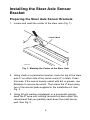
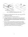
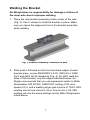
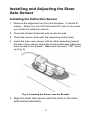
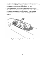
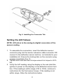
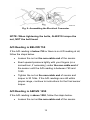
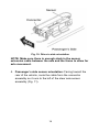
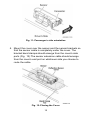
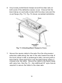
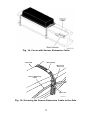
Self-Weighing Truck and Trailer Scales ™ Air-Weigh Scales Welded Steer Axle Deflection Sensor Kit Installation Guide For Use on Vehicles with Steel Spring Steer Axles Please Read Before Installing 901-0146-001 R0 Table of Contents ABOUT STEER AXLE DEFLECTION SENSORS ........................... 3 TOOLS REQUIRED ....................................................................... 4 Optional Tools .................................................................. 4 INSTALLING THE STEER AXLE SENSOR BRACKET .................. 5 Preparing the Steer Axle Sensor Brackets ........................... 5 Welding the Bracket ............................................................ 7 Adding a Protective Spray Paint Coating ............................. 8 INSTALLING AND ADJUSTING THE STEER AXLE SENSOR ...... 9 Installing the Deflection Sensor ........................................... 9 Setting the A/D Values ...................................................... 11 A/D Reading is BELOW 750 ........................................... 12 A/D Reading is ABOVE 1250.......................................... 12 Final Sensor Torque ....................................................... 13 Steer Axle Finishing Touches ............................................ 13 LIMITED WARRANTY ................................................................. 18 PROCEDURE FOR WARRANTY CLAIMS ................................... 19 2 About Steer Axle Deflection Sensors The Air-Weigh steer axle deflection sensor is a major component of several tractor and truck scale kits. Once installed, it allows the user to determine the weight resting on a spring-ride steer axle. This installation guide provides instructions for welding the steer axle brackets and installing the deflection sensor. See the User Guide included with your kit for complete scale installation, calibration and operation instructions. Follow the installation procedures in this guide exactly for the most accurate weighing. This guide assumes that you have already installed the QuickLoad or LoadMaxx display and, if you are using a LoadMaxx scale, the Comlink, or that you have access to a deflection sensor test box. You will need to connect the deflection sensor to either the display or the test box in order to adjust the sensor correctly. Please see the User Guide, included with your scale kit, to calibrate your scale after installation. 3 Tools Required You will need to supply to following tools to install deflection sensors on the steer and drive axles. Sander/grinder 40-grit medium sandpaper Chalk or permanent marker MIG or ARC welder For ARC welder: E7018 welding electrodes OR For MIG welder: E70S-3 or E71T-1 welding wire At least two C clamps Flat-blade screwdriver 9/16-inch combination wrench Torque wrench, 20 – 80 ft-lb 9/16-inch socket and 3/8-inch socket handle Enamel spray paint, any color Tape measure Optional Tools Deflection sensor test box, p/n 1001 4 Installing the Steer Axle Sensor Bracket Preparing the Steer Axle Sensor Brackets 1. Locate and mark the center of the steer axle (Fig. 1) Center Mark AW5800-1024 Fig. 1: Marking the Center of the Steer Axle 2. Using chalk or a permanent marker, mark the top of the steer axle 3" on either side of the center mark (6" in total). Clean this area. If the axle is heavily caked with dirt or grease, use Brakleen to remove the worst. Then clean the 6" area using two of the alcohol pads supplied in the installation kit. See Fig. 2. 3. Using 40-grit medium sandpaper or a pneumatic grinder, sand the 6" area until nothing remains but bare metal. We recommend that you partially sand down the mold line as well. See Fig. 2. 5 Alcohol Pad AW5800-1022 Fig. 2: Cleaning and Sanding the Steer Axle 4. Re-clean the sanded area on the steer axle using one of the supplied alcohol pads. 5. Re-mark the center of the steer axle (Fig. 1) 6. Verify that the bracket contact pads fit into the sanded area and that no axle paint is left under the pad. If there is any paint at all that will be touching the brackets, sand until it has been removed. 7. Once you have prepared the axle, place the new bracket onto the axle to ensure that it fits properly. All four bracket mounting pads should sit firmly on the axle without rocking in any direction. If the bracket rocks, sand or grind off any excess axle material until the bracket fits properly. 6 Welding the Bracket Air-Weigh takes no responsibility for damage or failure of the steer axle due to improper welding 1. Place the new bracket assembly at the center of the axle (Fig. 3). Use C clamps to hold the bracket in place. Make sure you leave the alignment tool in the bracket assembly while welding. Fig. 3: Bracket assembly centered on axle 2. Fillet weld a full bead on the front and back edges of each bracket piece, as per ANSI/AWS 2.4-79, AWS A5.4, AWS A5.9 and AWS A5.22 standards (Fig. 4). Do NOT weld the sides of the bracket, only the edges indicated below. AirWeigh recommends that you use equipment similar to Miller Shopmaster 300 AC/DC; AMP/VOLT setting of 22; wire speed of 3.5; and a welding argon gas mixture of 75/25. MIG welding should use Lincoln L-56 or Lincoln Arc L-56. MIG welding will use the same settings as the Miller Shopmaster noted above. 7 NOTE: Do not operate the vehicle while the alignment tool is still in place. Fig. 4: Welded axle and bracket Adding a Protective Spray Paint Coating To prevent steer axle corrosion, we recommend you spray paint around the base of the bracket. 1. Using any enamel-based spray paint, paint around the base of the bracket and over the welded section. Paint all bare metal around the bracket completely. 2. Once the paint is dry, we recommend that you paint all exposed metal a second time. Fig. 5: Spray Paint Coating 8 Installing and Adjusting the Steer Axle Sensor Installing the Deflection Sensor 1. Remove the alignment tool from the brackets. It should fit loosely. Retain the two 3/8" bolts and 3/8" nuts to use when you install the deflection sensor. 2. Clean the bracket channels with an alcohol pad. 3. Clean the sensor ends with the remaining alcohol pad. 4. Insert the steer axle sensor with its cable extending toward the side of the vehicle where the sensor extension cable has been routed to the firewall. Make sure the word “TOP” faces up (Fig. 6). Fig. 6: Inserting the Sensor into the Bracket 5. Align the steer axle sensor with the holes in the steer axle bracket assembly. 9 6. Insert one bolt through the bracket hole on the sensor end with the word “TOP” on it (Fig. 7). Place a washer and a nut at the end of the bolt and hand-tighten the nut. 7. Insert the second bolt through the second bracket hole. Place the connector assembly bracket tab on the other side of the bolt facing away from the bracket. Then place a washer and a nut behind the tab. Hand-tighten the nut (Fig. 8). Fig. 7: Attaching the Sensor to the Bracket 10 Fig. 8: Installing the Connector Tab Setting the A/D Values NOTE: A/D refers to the analog-to-digital conversion of the sensor reading. 1. To assemble the connectors, insert the deflection sensor connector plug into the sensor extension cable connector OR connect to the deflection sensor test box, not included in your installation kit. Ensure the locking tabs on the connector plug engage completely (Fig. 9). 2. Tighten both nuts and use a torque wrench to torque to 30 ftlbs. 3. Verify the A/D reading using the display in the cab (start the ignition to power on the display) or the deflection sensor test box. If the reading is within range (750 to 1250), continue to instructions for the final sensor torque. If the reading is not within range, follow the instructions below. 11 Fig. 9: Assembling the Electrical Connector NOTE: When tightening the bolts, ALWAYS torque the nut, NOT the bolt head. A/D Reading is BELOW 750 If the A/D reading is below 750 or there is no A/D reading at all, follow the steps below. Loosen the nut on the non-cable end of the sensor. Exert upward pressure lightly with your fingers (or a screwdriver, if necessary) under the non-cable end of the sensor until the A/D reading is between 750 and 1250. Tighten the nut on the non-cable end of sensor and torque to 30 ft-lbs. If the A/D readings are still within proper range, continue to instructions for the final sensor torque. A/D Reading is ABOVE 1250 If the A/D reading is above 1250, follow the steps below. Loosen the nut on the non-cable end of the sensor. 12 Exert downward pressure lightly with your fingers on the non-cable end of the sensor until the A/D reading is between 750 and 1250. Tighten nut and torque to 30 ft-lbs. If the A/D reading is still in range, proceed to instructions for the final sensor torque. Final Sensor Torque 1. Tighten both bolts to 60 ft-lbs. 2. Perform a final check of A/D values. If not within range, repeat the steps for altering A/D readings. 3. If you are using the deflection sensor test box to set A/D values, disconnect the box and connect the deflection sensor cable to the sensor extension cable. Steer Axle Finishing Touches 1. Slide the connector assembly onto the connector bracket tab mounted on the deflection sensor bracket, by inserting the tab into the grooves on the bottom side of the bracket. Ensure the connector assembly slides completely on the mounting tab. 2. Route the cable coming out of the receptacle portion of the connector assembly so it can be used for a driver’s side hookup or a passenger side hookup. 3. Driver’s side sensor orientation: Facing toward the rear of the vehicle, route the cable from the connector assembly so it runs to the right of the steer axle sensor assembly (Fig. 10). 13 Fig. 10: Driver’s side orientation NOTE: Make sure there is enough slack in the sensor extension cable between the axle and the frame to allow for axle movement. 4. Passenger’s side sensor orientation: Facing toward the rear of the vehicle, route the cable from the connector assembly so it runs to the left of the steer axle sensor assembly (Fig. 11). 14 Fig. 11: Passenger’s side orientation 5. Mount the cover over the sensor and the sensor brackets so that the sensor cable is completely under the cover. The bracket band clamps should emerge from the cover’s side ports (Fig. 12).The sensor extension cable should emerge from the cover’s end port on whichever side you choose to route the cable. Fig. 12: Placing the Cover 15 6. Very loosely install band clamps around the steer axle on both ends of the deflection sensor cover. Ensure that the band clamp on each side circles both the steer axle and the cover flange (Fig. 13). Fig. 14 shows completed installation. Fig. 13: Attaching Band Clamps to Cover 7. Secure the sensor cable to the axle. Run the drive sensor extension cable along the rear of the axle toward the side of the truck (driver’s side or passenger’s side), securing with a band clamp. Place split loom over the band clamp where it crosses over the cable. Secure the cable to the band clamp with nylon ties. See Fig. 15. Use additional 24” nylon ties as required to secure the cable to the steer axle. 16 Fig. 14: Cover with Sensor Extension Cable SteerAxle Band Clamp Split Loom Sleeving Sensor Extension Cable Nylon Tie AW5800-1037 Fig. 15: Securing the Sensor Extension Cable to the Axle 17 Limited Warranty For product failures due to material or manufacturing defects, Air-Weigh will replace or repair all components for up to 3 years from shipment date to the end-user Air-Weigh customer. These three-year components include: Displays, ComLinks, Sensors, Power Cables, Sensor Assemblies, Sensor Harnesses, and all other associated external components. Air-Weigh assumes no responsibility for administering warranty claims directly with any third party end users. The responsibility of Air-Weigh under this warranty is limited to the repair, replacement, or credit of the defective part or assembly. This warranty does not cover incidental or consequential damage to persons or property caused by use, abuse, misuse, or failure to comply with installation or operating instructions. This limited warranty does not apply to any product that has failed due to accident, abuse, alteration, installation not consistent with printed installation instructions, improper maintenance, improper operation, or as a result of system integration or installation not explicitly approved in writing by Air-Weigh. Air-Weigh and its resellers shall have no responsibility or liability for damages if the purchaser or any other person alters the vehicle incorporating Air-Weigh products. This limited warranty shall not apply to any product that has been repaired or altered by anyone not employed by Air-Weigh or not operated in accordance with the manufacturer’s printed material delivered with this product. Air-Weigh hereby expressly disclaims any and all implied warranties of any type, kind of nature whatsoever, and particularly any implied warranty of merchantability or fitness for a particular purpose not expressly stated by AirWeigh in its printed material delivered with its products. Some states do not allow the exclusion or limitation of incidental or consequential damages. If such laws apply, the limitations or exclusions contained in the terms and conditions of this Warranty may not apply. This warranty gives you specific legal rights and you may also have other rights, which vary state to state. May be covered by U.S. Patent Nos. 5478974, 5780782, 7478001 Foreign Patent Nos. 260494, 677998, 2122766 Copyright © 2004, 2006, 2007, 2010, 2011, 2012, 2013 by Hi-Tech Transport Electronics, Inc. All rights reserved. Air-Weigh®, ComLink™, and Hi-Tech Transport Electronics are trademarks or registered trademarks of Hi-Tech Transport Electronics, Incorporated. Other brand, product, or service names listed in this document are the trademarks or registered trademarks of their respective holders. Information contained in this literature was accurate at time of publication. Product changes may have been made after copyright dates that are not reflected in this document. 18 Procedure for Warranty Claims 1. For a warranty claim of an Air-Weigh product, customers should get the part number, serial number, and failure description of the failed item and call Air-Weigh Customer Support. Air-Weigh will replace or repair units that have failed due to workmanship, at the discretion of Air-Weigh. In the event that Air-Weigh requests to examine product prior to disposition, or for repairs or replacements, Air-Weigh requires a Return Material Authorization (RMA) number to be issued before the item is returned. Customers should contact Air-Weigh’s Customer Support Department at (888) 4593247 for an RMA number. Please reference this RMA number in all correspondence. 2. Claimed items shall be shipped freight pre-paid to: AirWeigh, Customer Support Department, 1730 Willow Creek Circle, Eugene, Oregon 97402, USA. The Air-Weigh RMA number shall appear on the outside of the return packaging. 3. Air-Weigh shall examine returned material within 30 days after receipt, or sooner if mutually agreed upon. If Air-Weigh determines that the part or assembly was defective in material or workmanship and within the warranty period, AirWeigh will repair or replace the part or assembly and return freight pre-paid. In the event Air-Weigh determines that the part or assembly cannot be repaired or replaced and is within the warranty period, a credit not to exceed the purchase price will be issued to the Air-Weigh customer. 4. Air-Weigh Accounting will process a credit memo and notify the Air-Weigh customer by email or fax. The Air-Weigh customer will process a corresponding debit memo and notify Air-Weigh Accounting. 5. If the part or assembly received by Air-Weigh does not meet the requirements of the warranty program set forth above, at the Air-Weigh customer’s request the part or assembly will either be discarded, returned freight collect, or repaired or replaced at the Air-Weigh customer’s expense and returned freight collect. 19 1730 Willow Creek Circle • Eugene, Oregon 97402-9152 USA P.O. Box 24308 • Eugene, Oregon 97402-0437 USA Telephone (541) 343-7884 • Order Desk (888) 459-3444 Customer Support (888) 459-3247 • FAX (541) 431-3121 Hours of Operation: Mon-Fri, 8am – 5pm, Pacific Time www.Air-Weigh.com 20