1
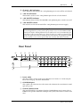
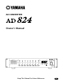
AD CONVERTER
Owner’s Manual
WORD CLOCK
INTERNAL
44.1kHz 48kHz
BNC
PEAK
SLOT
PEAK
NOMINAL
NOMINAL
SIGNAL
POWER
ON
OFF
SIGNAL
+48V
+48V
1
SEL
GAIN
dB
2
3
4
5
6
7
+48V MASTER
OFF ON
8
SEL
AD CONVERTER
Keep This Manual For Future Reference.
E
FCC INFORMATION (U.S.A.)
1. IMPORTANT NOTICE: DO NOT MODIFY THIS UNIT! This product, when installed as indicated in the instructions contained in this manual, meets FCC
requirements. Modifications not expressly approved by Yamaha may void your authority, granted by the FCC, to use the product.
2. IMPORTANT: When connecting this product to accessories and/or another product use only high quality shielded cables. Cable/s supplied with this product MUST
be used. Follow all installation instructions. Failure to follow instructions could void your FCC authorization to use this product in the USA.
3. NOTE: This product has been tested and found to comply with the requirements listed in FCC Regulations, Part 15 for Class “B” digital devices. Compliance with
these requirements provides a reasonable level of assurance that your use of this product in a residential environment will not result in harmful interference with
other electronic devices. This equipment generates/uses radio frequencies and, if not installed and used according to the instructions found in the users manual, may
cause interference harmful to the operation of other electronic devices. Compliance with FCC regulations does not guarantee that interference will not occur in all
installations. If this product is found to be the source of interference, which can be determined by turning the unit “OFF” and “ON”, please try to eliminate the
problem by using one of the following measures: Relocate either this product or the device that is being affected by the interference. Utilize power outlets that are on
different branch (circuit breaker or fuse) circuits or install AC line filter/s. In the case of radio or TV interference, relocate/reorient the antenna. If the antenna lead-in
is 300 ohm ribbon lead, change the lead-in to coaxial type cable. If these corrective measures do not produce satisfactory results, please contact the local retailer
authorized to distribute this type of product. If you can not locate the appropriate retailer, please contact Yamaha Corporation of America, Electronic Service
Division, 6600 Orangethorpe Ave, Buena Park, CA 90620
The above statements apply ONLY to those products distributed by Yamaha Corporation of America or its subsidiaries.
WARNING: THIS APPARATUS MUST BE EARTHED
IMPORTANT
THE WIRES IN THIS MAINS LEAD ARE COLOURED IN
ACCORDANCE WITH THE FOLLOWING CODE:
GREEN-AND-YELLOW :
EARTH
BLUE :
NEUTRAL
BROWN :
LIVE
As the colours of the wires in the mains lead of this apparatus may
not correspond with the coloured markings identifying the terminals in
your plug, proceed as follows:
The wire which is coloured GREEN and YELLOW must be
connected to the terminal in the plug which is marked by the letter E
or by the safety earth symbol
or coloured GREEN and YELLOW.
The wire which is coloured BLUE must be connected to the terminal
which is marked with the letter N or coloured BLACK.
The wire which is coloured BROWN must be connected to the
terminal which is marked with the letter L or coloured RED.
ADVARSEL!
Lithiumbatteri—Eksplosionsfare ved fejlagtig
håndtering. Udskiftning må kun ske med batteri
af samme fabrikat og type. Levér det brugte
batteri tilbage til leverandoren.
VARNING
Explosionsfara vid felaktigt batteribyte. Använd
samma batterityp eller en ekvivalent typ som
rekommenderas av apparattillverkaren.
Kassera använt batteri enligt fabrikantens
instruktion.
VAROITUS
Paristo voi räjähtää, jos se on virheellisesti
asennettu. Vaihda paristo ainoastaan
laitevalmistajan suosittelemaan tyyppiin. Hävitä
käytetty paristo valmistajan ohjeiden
mukaisesti.
* This applies only to products distributed by YAMAHA KEMBLE
MUSIC (U.K.) LTD.
NEDERLAND
THE NETHERLANDS
● Dit apparaat bevat een lithium batterij voor geheugen
back-up.
● This apparatus contains a lithium battery for memory
back-up.
● Raadpleeg uw leverancier over de verwijdering van de
batterij op het moment dat u het apparaat ann het einde
van de levensduur afdankt of de volgende Yamaha Service
Afdeiing:
Yamaha Music Nederland Service Afdeiing
Kanaalweg 18-G, 3526 KL UTRECHT
Tel. 030-2828425
● For the removal of the battery at the moment of the
disposal at the end of the service life please consult your
retailer or Yamaha Service Center as follows:
Yamaha Music Nederland Service Center
Address: Kanaalweg 18-G, 3526 KL
UTRECHT
Tel: 030-2828425
● Gooi de batterij niet weg, maar lever hem in als KCA.
● Do not throw away the battery. Instead, hand it in as small
chemical waste.
i
Important Information
Please read the following before using the AD824
Warnings
• Do not subject the AD824 to extreme temperatures, humidity, direct sunlight, or dust,
which could be a potential fire or electrical shock hazard.
• Do not allow water to enter the AD824 or allow it to become wet. Fire or electrical shock
may result.
• Connect the power cord only to an AC outlet of the type stated in this Owner’s Manual
or as marked on the AD824. Failure to do so is a fire and electrical shock hazard.
• Hold the power-cord plug when disconnecting from an AC outlet. Never pull the cord.
A power cord damaged through pulling is a potential fire and electrical shock hazard.
• Do not touch the power plug with wet hands. Doing so is a potential electrical shock
hazard.
• Do not place heavy objects, including the AD824, on top of the power cord. A damaged
power cord is a fire and electrical shock hazard. In particular, be careful not to place
heavy objects on a power cord covered by a carpet.
• Do not scratch, bend, twist, pull, or heat the power cord. A damaged power cord is a
fire and electrical shock hazard.
• If the power cord is damaged (e.g., cut or a bare wire is exposed), ask your dealer for a
replacement. Using the AD824 with a damaged power cord is a fire and electrical shock
hazard.
• Do not plug several devices into the same AC outlet. This may overload the AC outlet,
and could be a fire or electrical shock hazard. It may also affect the performance of some
equipment.
• If you notice any abnormality, such as smoke, odor, or noise, or if a foreign object or
liquid gets inside the AD824, turn it off immediately. Remove the power cord from the
AC outlet and consult your dealer for repair. Using the AD824 in this condition is a fire
and electrical shock hazard.
• Do not place small objects on top of the AD824. Metal objects falling inside the AD824
is a fire and electrical shock hazard.
• If a foreign object or water gets inside the AD824, turn it off immediately. Remove the
power cord from the AC outlet and consult your dealer for repair. Using the AD824 in
this condition is a potential fire and electrical shock hazard.
• Should the AD824 be dropped or the cabinet be damaged, turn off the power, remove
the power plug from the AC outlet, and contact your dealer. If you continue using the
unit without heeding this instruction, fire or electrical shock may result.
• Do not remove the AD824’s cover. You could receive an electrical shock. If you think
internal inspection, maintenance, or repair is necessary, contact your dealer.
• Do not attempt to modify the AD824. This is a potential fire and electrical shock hazard.
• Do not block the AD824 ventilation slots. Blocking the ventilation slots is a potential
fire hazard.
AD824—Owner’s Manual
ii
Cautions
• Allow enough free space around the unit for normal ventilation. This should be: 10 cm
at the sides, 15 cm behind, and 30 cm above. These distances should also be adopted
when rack-mounting the AD824. For normal ventilation during use, remove the rear
of the rack or open a ventilation hole. If the airflow is not adequate, the AD824 will heat
up inside and may cause a fire.
• Use the AD824 in an environment with a temperature of between 10˚C and 35˚C (50˚F
and 95˚F).
• Turn off all equipment before connecting it to the AD824, and use only the cables specified in the relevant owner’s manuals.
• If you plan not to use the AD824 for a long period of time, remove the power cord from
the AC outlet. Leaving the AD824 connected is a potential fire hazard.
• Do not use benzene, thinner, cleaning detergent, or a chemical cloth to clean the
AD824. Use only a soft, dry cloth.
• If the AD824 is stored in a cold place (e.g., overnight in a car), and then moved to a
warmer environment, or the temperature rises sharply, condensation may form inside
the AD824, which may affect performance. In such cases, the AD824 should be allowed
to acclimatize for about one hour before use.
• When the wordclock source is changed on the wordclock master device (e.g., this
AD824, a DME32 or 02R), noise may occur from the outputs of the wordclock slave
devices, especially a AD824 with an MY8-AT I/O card installed, so turn down your
power amps beforehand, otherwise any connected speakers may be damaged.
• If the error code “E1” or “E3” appears on the GAIN display when the AD824 is turned
on, see your dealer about changing the internal backup battery. Although the AD824
will work even when the battery voltage is low, it may not remember the current settings
next time it’s turned on.
Interference
The AD824 uses high-frequency digital circuits that may cause interference on radio
and television equipment located nearby. If interference is a problem, relocate the
affected equipment.
AD824 Exclusion of Certain Responsibility
Manufacturer, importer, or dealer shall not be liable for any incidental damages including personal injury or any other damage caused by improper use or operation of the
AD824.
Yamaha cannot be held responsible for any loss of data or data damage due to improper
use or operation of the AD824.
Package Contents
The AD824 package should contain the following items. Contact your Yamaha dealer if
anything is missing.
• AD824 AD Converter
• 9-pin D-sub crossed cable (1.5 m)
• This manual
AD824—Owner’s Manual
iii
Trademarks
ADAT MultiChannel Optical Digital Interface is a trademark of Alesis Corporation.
Tascam Digital Interface is a trademark and Tascam and Teac are registered trademarks
of Teac Corporation. Yamaha is a trademark of Yamaha Corporation. All other trademarks are the property of their respective holders and are hereby acknowledged.
Copyright
No part of the AD824 software or this Owner’s Manual may be reproduced or distributed in any form or by any means without the prior written authorization of Yamaha
Corporation.
© 2000 Yamaha Corporation. All rights reserved.
AD824—Owner’s Manual
iv
Contents
Contents
1
Introduction . . . . . . . . . . . . . . . . . . . . . . . . . . . . . . . . 1
Welcome . . . . . . . . . . . . . . . . . . . . . . . . . . . . . . . . . . . . . . . . . . . . . . . . . . . . . . . . . . .
Installation . . . . . . . . . . . . . . . . . . . . . . . . . . . . . . . . . . . . . . . . . . . . . . . . . . . . . . . . .
Connecting the Power Cord . . . . . . . . . . . . . . . . . . . . . . . . . . . . . . . . . . . . . . . . . . .
Turning On the Power . . . . . . . . . . . . . . . . . . . . . . . . . . . . . . . . . . . . . . . . . . . . . . .
2
1
1
1
1
Touring the AD824 . . . . . . . . . . . . . . . . . . . . . . . . . . . 2
Front Panel . . . . . . . . . . . . . . . . . . . . . . . . . . . . . . . . . . . . . . . . . . . . . . . . . . . . . . . . . 2
Rear Panel . . . . . . . . . . . . . . . . . . . . . . . . . . . . . . . . . . . . . . . . . . . . . . . . . . . . . . . . . . 3
3
Operation . . . . . . . . . . . . . . . . . . . . . . . . . . . . . . . . . . 5
Selecting the Wordclock Source . . . . . . . . . . . . . . . . . . . . . . . . . . . . . . . . . . . . . . . .
Setting the Phantom Power for Each Channel . . . . . . . . . . . . . . . . . . . . . . . . . . . .
Setting the +48V Phantom Power Master . . . . . . . . . . . . . . . . . . . . . . . . . . . . . . . .
Setting the Gain . . . . . . . . . . . . . . . . . . . . . . . . . . . . . . . . . . . . . . . . . . . . . . . . . . . . .
Controlling the AD824 Remotely . . . . . . . . . . . . . . . . . . . . . . . . . . . . . . . . . . . . . .
4
5
5
6
6
6
Digital I/O Cards . . . . . . . . . . . . . . . . . . . . . . . . . . . . . 7
About Digital I/O Cards . . . . . . . . . . . . . . . . . . . . . . . . . . . . . . . . . . . . . . . . . . . . . . 7
Card Specifications . . . . . . . . . . . . . . . . . . . . . . . . . . . . . . . . . . . . . . . . . . . . . . . . . . 7
Installing I/O Cards . . . . . . . . . . . . . . . . . . . . . . . . . . . . . . . . . . . . . . . . . . . . . . . . . . 8
5
Hookup Examples . . . . . . . . . . . . . . . . . . . . . . . . . . . . 9
Basic AES/EBU Connection . . . . . . . . . . . . . . . . . . . . . . . . . . . . . . . . . . . . . . . . . . . 9
Basic ADAT Connection . . . . . . . . . . . . . . . . . . . . . . . . . . . . . . . . . . . . . . . . . . . . . . 9
AES/EBU Connection with Splitter Cable . . . . . . . . . . . . . . . . . . . . . . . . . . . . . . . 10
Dual ADAT Connection . . . . . . . . . . . . . . . . . . . . . . . . . . . . . . . . . . . . . . . . . . . . . . 10
Insert Connection . . . . . . . . . . . . . . . . . . . . . . . . . . . . . . . . . . . . . . . . . . . . . . . . . . . 11
Personal Computer Connection . . . . . . . . . . . . . . . . . . . . . . . . . . . . . . . . . . . . . . . 11
Yamaha DME32 Connection . . . . . . . . . . . . . . . . . . . . . . . . . . . . . . . . . . . . . . . . . . 12
Multiple AD824 Connection . . . . . . . . . . . . . . . . . . . . . . . . . . . . . . . . . . . . . . . . . . 13
6
Wordclocks . . . . . . . . . . . . . . . . . . . . . . . . . . . . . . . . . 14
About Wordclocks . . . . . . . . . . . . . . . . . . . . . . . . . . . . . . . . . . . . . . . . . . . . . . . . . . . 14
Wordclock Hookup Examples . . . . . . . . . . . . . . . . . . . . . . . . . . . . . . . . . . . . . . . . . 14
Wordclock Termination . . . . . . . . . . . . . . . . . . . . . . . . . . . . . . . . . . . . . . . . . . . . . . 15
Appendix . . . . . . . . . . . . . . . . . . . . . . . . . . . . . . . . . . . 16
Error Messages . . . . . . . . . . . . . . . . . . . . . . . . . . . . . . . . . . . . . . . . . . . . . . . . . . . . . . 16
Specifications . . . . . . . . . . . . . . . . . . . . . . . . . . . . . . . . . . . . . . . . . . . . . . . . . . . . . . . 16
Dimensions . . . . . . . . . . . . . . . . . . . . . . . . . . . . . . . . . . . . . . . . . . . . . . . . . . . . . . . . 18
AD824—Owner’s Manual
Introduction
1
1 Introduction
Welcome
Thank you for choosing the Yamaha AD824 AD Converter. The AD824 is a high-performance 8-channel analog-to-digital converter, with 24-bit linear analog-to-digital
converters and 128-times oversampling, providing a typical dynamic range of 110 dB.
Optional mini YGDAI (Yamaha General Digital Audio Interface) cards offer a variety
of digital output interfaces, with support for all the popular digital audio interconnect
formats, including AES/EBU, ADAT, and Tascam TDIF-1.
Analog inputs feature electronically balanced XLRs, high-quality mic preamps, independently switchable 48-volt phantom powering, and rotary gain adjustment. Inputs
can be used with either microphones or line-level sources. Analog outboard equipment
can be patched into each channel by using the electronically-balanced analog insert
points on two 1/4" TRS phone jacks.
Remote control from a Yamaha DME32, personal computer, or other device is possible
using an exclusive control protocol.
Installation
The AD824 can be used freestanding on a stable surface, somewhere that complies with
the important information at the beginning of this manual, or mounted in a rack.
When mounting the AD824 in a rack, leave adequate ventilation space around the
AD824 (at least 10 cm of free space behind). If the AD824 is mounted in a portable rack
case, keep the rear of the case open when using the AD824 so as not to obstruct the flow
of air from the air vents. Do not mount the AD824 next to equipment that produces a
lot of heat, such as a power amplifier.
Connecting the Power Cord
Warning: Turn off all equipment before making any connections.
Connect the power-cord plug to a suitable AC wall outlet, one that conforms to the
power supply requirements stated on the AD824 rear panel.
Turning On the Power
To prevent audible thumps and clicks, turn on your audio equipment in
the following order (reverse this order when turning off)—sound
sources, AD824, mixer or recorder (e.g., 02R, DME32, D24, etc.), power
amplifiers.
1
POWER
ON
OFF
Press the [POWER] switch to turn on the AD824.
The AD824 starts up and the POWER indicator lights up.
2
Press the [POWER] switch again to turn off the AD824.
The POWER indicator goes out.
AD824—Owner’s Manual
2
Chapter 2—Touring the AD824
2 Touring the AD824
Front Panel
1
WORD CLOCK
INTERNAL
44.1kHz 48kHz
BNC
2
PEAK
PEAK
NOMINAL
SLOT
3
GAIN
NOMINAL
SIGNAL
45
POWER
ON
OFF
dB
SIGNAL
+48V MASTER
+48V
+48V
1
2
3
4
5
6
7
SEL
OFF ON
8
SEL
AD CONVERTER
6 789
J
K LM
A PEAK, NOMINAL & SIGNAL indicators
These indicators show the signal level of each channel and light up as follows:
PEAK 3 dB below maximum input level.
NOMINAL 14 dB below maximum input level.
SIGNAL 34 dB below maximum input level.
B GAIN display
This 3-digit, 7-segment display shows the gain setting of the selected channel.
C GAIN control
This rotary control is used to set the gain of the selected channel.
D POWER indicator
This indicator lights up when the AD824 is powered up.
E POWER switch
This switch is used to turn on the power to the AD824. See “Turning On the Power” on
page 1 for more information.
F WORD CLOCK indicators
These indicators show the selected wordclock source. When the AD824 cannot lock to
the selected source, the corresponding indicator flashes.
G WORD CLOCK Source button
This button is used to select the wordclock source: 44.1 kHz internal, 48 kHz internal,
BNC, or SLOT.
H Channel SEL indicators
These indicators show which channel is currently selected.
I Channel SEL buttons
These buttons are used to select channels for use with the gain and +48V phantom
power functions.
AD824—Owner’s Manual
3
Rear Panel
J Channel +48V indicators
These indicators show whether the +48V phantom power is on or off for each channel.
K +48V on/off button
This button is used to set the +48V phantom power for the selected channel.
L +48V MASTER indicator
This indicator shows whether the MASTER +48V phantom power switch is on or off.
M +48V MASTER switch
This switch is used to turn on and off the +48V phantom power master supply.
Security Cover
For certain applications you may wish to fit a protective cover over the AD824’s GAIN
controls and switches. Although Yamaha do not make such a cover, the AD824 has four
fixing holes to affix a custom-made cover. If you fit such a cover, make sure that the fixing
screws do not protrude inside the AD824 by more than 10 mm. The fixing holes accept
M3-size machine screws, and are spaced 45.0 mm vertically, 410 mm horizontally.
Rear Panel
2
3
4
5
WORD CLOCK
COM
NVERTER
AD824
6 7
OUT
RS422
PC RS422
8
7
6
5
4
3
2
1
75Ω
IN
ON OFF
INPUT
8
OUT
J
(BAL)
SLOT
8
7
6
5
4
3
2
1
(BAL)
8
7
6
5
4
3
2
1
INSERT
IN
(BAL)
1
K
9
A Power cable
The power cable is used to connect the AD824 to an AC outlet. See “Connecting the
Power Cord” on page 1 for more information.
B COM RS422 port
This 9-pin D-sub connector is used to connect the AD824 to the next AD824 in a multiple-unit system.
C COM PC/RS422 switch
This switch should be set to RS422 when the COM PC/RS422 port is connected to a
DME32 or the previous AD824 in a multiple-unit system, or PC when it’s connected to
a PC.
AD824—Owner’s Manual
4
Chapter 2—Touring the AD824
D COM PC/RS422 port
This 9-pin D-sub connector is for connecting the AD824 to a device for remote control,
such as a Yamaha DME32 or personal computer. It’s also used to connect to the previous AD824 in a multiple-unit system.
E WORD CLOCK OUT connector
This BNC connector transmits the wordclock signal.
F WORD CLOCK 75Ω ON/OFF switch
This switch is used to terminate the wordclock signal received at the WORD CLOCK
IN. See “Wordclocks” on page 14 for more information.
G WORD CLOCK IN connector
This BNC connector is used to connect an external wordclock source. See “Wordclocks”
on page 14 for more information.
H INPUT (BAL) connectors
These female XLR-3-31-type connectors are the analog inputs. They’re electronically
balanced and are wired as follows: pin-1 ground, pin-2 hot (+), and pin-3 cold (–).
hot
ground
cold
I SLOT
This slot is for use with optional mini YGDAI cards, which offer various digital output
options. See “Digital I/O Cards” on page 7 for more information.
J INSERT OUT (BAL) connectors
These balanced 1/4" TRS phone jacks are the insert outputs, or send connectors. The
insert point on each channel is located between the head amplifier and A/D converter.
They’re electronically balanced and are wired as follows: tip=hot, ring=cold, and
sleeve=ground.
ground
hot
cold
K INSERT IN (BAL) connectors
These balanced 1/4" TRS phone jacks are the insert inputs, or return connectors. The
insert point on each channel is located between the head amplifier and A/D converter.
The signal level indicators are located after the INSERT IN connector. They’re electronically balanced and are wired as follows: tip=hot, ring=cold, and sleeve=ground.
ground
cold
AD824—Owner’s Manual
hot
Operation
5
3 Operation
Selecting the Wordclock Source
The wordclock source can be set to 44.1 kHz internal, 48 kHz internal, BNC, or SLOT.
Note: When the wordclock source is changed on the wordclock master device (e.g., this
AD824, a DME32 or 02R), noise may occur from the outputs of the wordclock slave
devices, especially a AD824 with an MY8-AT I/O card installed, so turn down your power
amps beforehand, otherwise any connected speakers may be damaged.
1
Use the [WORD CLOCK] button to select a source.
The corresponding wordclock indicator flashes quickly.
2
While the indicator is flashing, press the [WORD CLOCK] button again.
The wordclock source changes and the corresponding indicator stops flashing and
lights up continuously. The indicator of previously selected wordclock source goes out.
When the AD824 cannot lock to the selected wordclock source, the corresponding indicator flashes.
See page 14 for more information on wordclocks.
Setting the Phantom Power for Each Channel
The +48V phantom power can be turned on and off for each channel individually.
Note: In order to use the +48V phantom power the +48V MASTER switch must be in
the ON position.
1
Use the [SEL] buttons to select a channel.
The selected channel’s SEL indicator lights up.
2
Press the +48V on/off button.
The channel’s +48V indicator flashes quickly.
3
While the indicator is flashing, press the [+48V] button again to turn the channel’s +48V phantom power on or off.
The channel’s +48V indicator lights up when the phantom power is on, and goes off
when it’s turned off.
AD824—Owner’s Manual
6
Chapter 3—Operation
Setting the +48V Phantom Power Master
The +48V phantom power for all channels can be turned on and off by using the +48V
MASTER switch.
1
Set the +48V MASTER switch to the ON position to turn on the +48V phantom
power master supply.
The +48V MASTER indicator lights up.
2
Set the +48V MASTER switch to the OFF position to turn off the +48V phantom
power master supply.
The +48V MASTER indicator goes out.
Note that the channel +48V indicators remain lit when the +48V MASTER switch is set
to the OFF position.
Setting the Gain
The head-amp gain for each channel can be set individually.
1
Use the [SEL] buttons to select a channel.
The selected channel’s SEL indicator lights up and the gain setting appears on the GAIN
display.
2
Use the GAIN control to set the gain.
The gain can be set in 6 dB steps.
Controlling the AD824 Remotely
Using an exclusive control protocol, the AD824 can be remotely controlled from a
Yamaha DME32, personal computer, or other device connected to the COM PC/RS422
port. In addition, several AD824s can be remotely controlled by connecting them
together in a chain-like fashion by using both the COM PC/RS422 port and the COM
RS422 port.
When a control signal is detected, the GAIN display indicates the AD824’s ID number,
which is useful for identifying AD824s in a multiple-unit system. When an operation is
next performed on the AD824, the ID number disappears. ID numbers are determined
by the position of each AD824 in the connection chain and are set automatically.
The COM PC/RS422 switch should be set to RS422 when the COM PC/RS422 port is
connected to a DME32 or the next AD824 in a multiple-unit system, or PC when it’s
connected to a PC.
Note: When connecting to an AD824’s COM PC/RS422 port and COM RS422 port, be
careful not to create a loop connection between them.
See “Personal Computer Connection” on page 11 and “Yamaha DME32 Connection”
on page 12 for hookup examples.
AD824—Owner’s Manual
Digital I/O Cards
7
4 Digital I/O Cards
About Digital I/O Cards
For digital output the AD824 uses optional mini YGDAI (Yamaha General Digital
Audio Interface) cards, which are available in all the popular digital audio interconnect
formats, including AES/EBU, ADAT, and Tascam TDIF-1.
The following digital I/O cards are currently available. See the Yamaha Professional
Audio Web site at the following address for up-to-date news on mini YGDAI cards:
<http://www.yamaha.co.jp/product/proaudio/homeenglish/>.
MY8-AT—ADAT
The MY8-AT card provides ADAT format digital I/O via two MultiChannel Optical
Digital Interface connectors, and supports 16-, 20-, and 24-bit wordlengths.
MY8-AE—AES/EBU
The MY8-AE card provides AES/EBU format digital I/O via a 25-pin D-sub connector,
and supports 16-, 20-, and 24-bit wordlengths.
MY8-TD—Tascam TDIF-1
The MY8-TD card provides Tascam TDIF-1 format digital I/O via a 25-pin D-sub connector, and supports 16-, 20-, and 24-bit wordlengths. A BNC connector is provided
for wordclock output.
MY8-TD cards feature a device selector switch (EXT: 88/INT: 38) that should be set to
match the device being connected. This should be set to “EXT: 88” when connecting a
Tascam DA-88, or “INT: 38” when connecting a Tascam DA-38, DME32, or other
device.
Card Specifications
The following table provides specifications for the AD824-compatible I/O cards.
Card
Format
In
Out
Wordlength
Connectors
MY8-AT
ADAT I/O
8
8
16, 20, 24
Optical x2
MY8-AE
AES/EBU I/O
8
8
16, 20, 24
25-pin D-sub
(cable not included)
MY8-TD
Tascam TDIF-1 I/O
8
8
16, 20, 24
25-pin D-sub,
BNC wordclock out
AD824—Owner’s Manual
8
Chapter 4—Digital I/O Cards
Installing I/O Cards
This section explains how to install mini YGDAI cards in the AD824.
1
Turn off the AD824.
2
Undo the two fixing screws and remove the slot cover, as shown below.
CO
M
PC
RS
42
2
OU
T
W
OR
D
SL
OT
CL
OC
K
7
ON 5Ω
OF
F IN
8
8
8
Keep the cover and fixing screws in a safe place for future use.
3
Insert the card between the guide rails and slide it all the way into the slot,
as shown below. You may have to push firmly to plug the card into the AD824
connector.
CO
M
PC
RS
42
2
OU
T
SL
OT
W
OR
D
CL
OC
K
7
ON 5Ω
OF
F IN
8
8
8
4
Secure the card using the attached thumbscrews. Do not leave the thumbscrews loose, as the card will not be grounded correctly.
AD824—Owner’s Manual
9
Hookup Examples
5 Hookup Examples
In the following hookup examples, the “digital audio device” could be any device with
a compatible AES/EBU or ADAT interface, including the following Yamaha products
with the necessary I/O cards installed: DME32 Digital Mixing Engine, 02R Digital
Recording Console, 03D Digital Mixing Console, 01V Digital Mixing Console, or D24
Digital Multitrack Recorder.
Basic AES/EBU Connection
This example shows how the
AD824 can be connected to a
digital audio device with an
AES/EBU interface by using
an MY8-AE I/O card and a
25-pin D-sub AES/EBU connecting cable. Either device
could be used as the wordclock master.
Digital Audio Device
(DME32, 02R, D24, etc.)
AES/EBU I/O
AES/EBU cable
SLOT: MY8-AE
AD824
WORD CLOCK
INTERNAL
44.1kHz 48kHz
BNC
PEAK
SLOT
PEAK
NOMINAL
NOMINAL
SIGNAL
GAIN
POWER
ON
OFF
dB
SIGNAL
+48V
+48V
1
2
3
4
5
6
7
+48V MASTER
OFF ON
8
SEL
SEL
AD CONVERTER
Analog intput x8
Basic ADAT Connection
This example shows how the
AD824 can be connected to a
digital audio device with an
ADAT interface by using a
MY8-AT I/O card and standard ADAT connecting cable.
The AD824 is the wordclock
master. In order to use the
digital audio device as the
wordclock master, its wordclock signal would need to be
fed to the AD824 using the
SLOT ADAT IN or BNC
WORD CLOCK IN.
Digital Audio Device
(DME32, 02R, D24, etc.)
IN
ADAT I/O
ADAT cable
AD824
OUT SLOT: MY8-AT
WORD CLOCK
INTERNAL
44.1kHz 48kHz
BNC
PEAK
SLOT
PEAK
NOMINAL
NOMINAL
SIGNAL
GAIN
POWER
ON
OFF
dB
SIGNAL
+48V
+48V
1
2
3
4
5
6
7
OFF ON
8
SEL
+48V MASTER
SEL
AD CONVERTER
Analog input x8
AD824—Owner’s Manual
10
Chapter 5—Hookup Examples
AES/EBU Connection with Splitter Cable
This example shows how both an AD824 and DA824 can be connected to a digital
audio device with a single AES/EBU interface by using MY8-AE I/O cards and a custom
AES/EBU splitter cable. Pin wiring details for the AES/EBU interface are supplied with
the MY8-AE I/O card. The digital audio device is the wordclock master, with the AD824
receiving its wordclock via a BNC connection, the DA824, via its slot input.
Digital Audio Device
(DME32, 02R, D24, etc.)
WC OUT
AES/EBU I/O
BNC cable
Custom AES/EBU splitter cable
AD824
WORD CLOCK
INTERNAL
44.1kHz 48kHz
SLOT: MY8-AE
WC IN
BNC
PEAK
SLOT
PEAK
NOMINAL
GAIN
NOMINAL
SIGNAL
PEAK
POWER
ON
OFF
dB
SLOT: MY8-AE
DA824
PEAK
NOMINAL
SIGNAL
1
2
3
4
5
6
7
2
3
4
5
6
7
8
+48V MASTER
+48V
OFF ON
8
SEL
POWER
ON
OFF
SIGNAL
1
+48V
LOCK
NOMINAL
SIGNAL
SEL
AD CONVERTER
DA CONVERTER
Analog output x8
Analog input x8
Dual ADAT Connection
This example shows how both an AD824 and DA824 can be connected to a digital
audio device with standard ADAT I/O by using MY8-AT I/O cards and standard ADAT
connecting cables. The digital audio device is the wordclock master, with the AD824
receiving its wordclock via a BNC connection, the DA824, via its slot input.
Digital Audio Device
(DME32, 02R, D24, etc.)
IN
WC OUT
BNC cable
OUT
ADAT I/O
ADAT cables
AD824
WORD CLOCK
INTERNAL
44.1kHz 48kHz
OUT
SLOT: MY8-AT
WC IN
BNC
PEAK
PEAK
SLOT
NOMINAL
NOMINAL
GAIN
PEAK
POWER
ON
OFF
dB
SIGNAL
SIGNAL
IN
SLOT: MY8-AT
DA824
PEAK
NOMINAL
NOMINAL
SIGNAL
+48V
+48V
1
2
SEL
3
4
5
6
7
2
3
4
5
6
7
POWER
ON
OFF
8
+48V MASTER
OFF ON
8
SEL
AD CONVERTER
Analog input x8
AD824—Owner’s Manual
LOCK
SIGNAL
1
DA CONVERTER
Analog output x8
11
Insert Connection
Insert Connection
This example shows how analog outboard equipment can be patched into each channel
by using the INSERT IN and OUT 1/4" TRS phone jacks. The insert point on each
channel is located between the head amplifier and A/D converter. The signal level indicators are located after the INSERT IN connector.
Digital Audio Device
(DME32, 02R, D24, etc.)
AES/EBU I/O
AES/EBU cable
SLOT: MY8-AE
AD824
Outboard equipment
Input
OUT
INSERT
WORD CLOCK
INTERNAL
44.1kHz 48kHz
PEAK
BNC
SLOT
PEAK
NOMINAL
NOMINAL
SIGNAL
+48V
+48V
1
2
3
4
5
6
7
POWER
ON
OFF
+48V MASTER
OFF ON
8
SEL
Output
GAIN
dB
SIGNAL
SEL
AD CONVERTER
IN
Analog intput x8
Personal Computer Connection
This example shows how a personal computer can be connected to the AD824 for
remote control. The computer is connected to the AD824’s COM PC/RS422 port, and
the COM PC/RS422 switch is set to PC.
Serial cable
AD824
COM PC/RS422
WORD CLOCK
INTERNAL
44.1kHz 48kHz
BNC
PEAK
SLOT
PEAK
NOMINAL
NOMINAL
SIGNAL
GAIN
POWER
ON
OFF
dB
SIGNAL
+48V
+48V
1
2
3
4
5
6
7
OFF ON
8
SEL
+48V MASTER
SEL
AD CONVERTER
COM port
Analog input x8
AD824—Owner’s Manual
12
Chapter 5—Hookup Examples
Yamaha DME32 Connection
The following example shows how the AD824 can be connected to the Yamaha DME32
Digital Mixing Engine for remote control. Channel gain and phantom power can be
remotely controlled and recalled from the DME32, which features Gain Trimmer components especially for use with the AD824. The COM PC/RS422 port on the AD824 is
connected to the COM port on the DME32. The AD824’s COM PC/RS422 switch is set
to RS422. The DME32 is the wordclock master, with the AD824 receiving its wordclock
via a BNC connection, the DA824, via its slot input.
DME32
SCENE NO.
88
CONFIGURATION
SCENE
DATA
XXXXXYAMAHAXDME32
XDigitalXMixingXEngine
COMPONENT
48kHz
PARAMETER
VALUE
44.1kHz
SCENE RECALL
7
8
9
4
5
6
1
2
3
STORE
0
RECALL
INC
POWER
ON
OFF
DEC
USER DEFINE
LOCK
EMERGENCY
PROTECT
UTILITY
CARD
BNC cable
WC OUT
COM
9-pin cable
WORD CLOCK
INTERNAL
44.1kHz 48kHz
BNC
Custom AES/EBU splitter cable
PEAK
PEAK
SLOT
AES/EBU I/O
SLOT: MY8-AE
COM PC/RS422
WC IN
DIGITAL MIXING ENGINE
NOMINAL
NOMINAL
SLOT: MY8-AE
GAIN
POWER
ON
OFF
dB
NOMINAL
NOMINAL
SIGNAL
SIGNAL
PEAK
PEAK
1
+48V
+48V
1
2
SEL
3
4
5
6
7
2
3
4
5
6
7
POWER
ON
OFF
8
+48V MASTER
OFF ON
8
SEL
AD CONVERTER
AD824
DA CONVERTER
DA824
Analog input x8
AD824—Owner’s Manual
LOCK
SIGNAL
SIGNAL
Analog output x8
Multiple AD824 Connection
13
Multiple AD824 Connection
The next example shows how the AD824 COM ports can be used to connect several
AD824s in combination with a DME32. The COM PC/RS422 port on the AD824 #1 is
connected to the COM port on the DME32, while the COM RS422 port on AD824 #1
is connected to the COM PC/RS422 port on AD824 #2. The COM PC/RS422 switches
on both AD824s are set to RS422. The DME32 is the wordclock master and both the
AD824s receive their wordclocks via their SLOT inputs.
DME32
SCENE NO.
CONFIGURATION
88
SCENE
DATA
SCENE RECALL
XXXXXYAMAHAXDME32
XDigitalXMixingXEngine
COMPONENT
48kHz
PARAMETER
7
8
9
4
5
6
1
2
3
STORE
0
RECALL
INC
VALUE
POWER
ON
OFF
DEC
44.1kHz
USER DEFINE
LOCK
EMERGENCY
PROTECT
UTILITY
CARD
DIGITAL MIXING ENGINE
SLOT 1
SLOT 2
COM
9-pin cable
SLOT
AD824 #1
WORD CLOCK
INTERNAL
44.1kHz 48kHz
BNC
COM PC/RS422
PEAK
SLOT
PEAK
NOMINAL
NOMINAL
SIGNAL
GAIN
POWER
ON
OFF
dB
SIGNAL
+48V
+48V
1
2
3
4
5
6
7
+48V MASTER
OFF ON
8
SEL
SEL
AD CONVERTER
COM RS422
Analog input x8
9-pin cable
SLOT
AD824 #2
WORD CLOCK
INTERNAL
44.1kHz 48kHz
BNC
COM PC/RS422
PEAK
SLOT
PEAK
NOMINAL
NOMINAL
SIGNAL
GAIN
POWER
ON
OFF
dB
SIGNAL
+48V
+48V
1
2
3
4
5
6
7
+48V MASTER
OFF ON
8
SEL
SEL
AD CONVERTER
COM RS422
Analog input x8
AD824—Owner’s Manual
14
Chapter 6—Wordclocks
6 Wordclocks
About Wordclocks
For correct operation and analog-to-digital conversion, it’s essential that the AD824 is
wordclock locked to the digital audio device connected to its SLOT output. The AD824
can generate a wordclock signal internally at either 44.1 kHz or 48 kHz, so it could be
used as the wordclock master, in which case the device connected to the SLOT would
be used as a wordclock slave. Alternatively, the AD824 can lock to an external wordclock
signal derived from its SLOT, or a wordclock signal received at the WORD CLOCK IN
connector.
See page 5 for information on selecting the wordclock source.
Wordclock Hookup Examples
In this example, the AD824
sources its wordclock signal
from its SLOT. Note that the
AD824 is transmitting digital
audio to the digital audio device
and deriving a wordclock signal
from it all down the same cable.
This works okay with AES/EBU
and Tascam TDIF-1 digital connections, because a single cable is
all that’s required to transmit
and receive digital audio. With
the ADAT format, however, separate optical cables are used to
transmit and receive, so in order
to transmit digital audio and
derive a wordclock signal, both
the ADAT IN and OUT on the
AD824 must be connected to the
digital audio device.
Digital Audio Device
(DME32, 02R, D24, etc.)
Digital I/O
Digital audio
Wordclock
MY8-xx
AD824
WORD CLOCK
INTERNAL
44.1kHz 48kHz
BNC
PEAK
SLOT
PEAK
GAIN
NOMINAL
NOMINAL
SIGNAL
POWER
ON
OFF
dB
SIGNAL
+48V MASTER
+48V
+48V
1
2
3
4
5
6
7
OFF ON
8
SEL
SEL
AD CONVERTER
Wordclock source = SLOT
In this example, the AD824
sources its wordclock signal
from its BNC WORD CLOCK
IN connector.
Digital Audio Device
(DME32, 02R, D24, etc.)
Wordclock out
(BNC)
Digital
audio
Wordclock
MY8-xx
AD824
WORD CLOCK
INTERNAL
44.1kHz 48kHz
Digital I/O
BNC
WORD CLOCK IN
PEAK
SLOT
PEAK
NOMINAL
NOMINAL
SIGNAL
+48V
+48V
1
SEL
GAIN
POWER
ON
OFF
dB
SIGNAL
2
3
4
5
6
7
+48V MASTER
OFF ON
8
SEL
AD CONVERTER
Wordclock source = BNC
AD824—Owner’s Manual
Wordclock Termination
15
Wordclock Termination
For correct and reliable operation, wordclock signals distributed via BNC cables must
be terminated correctly. Termination is typically applied at the last device, although it
depends on the distribution method being used. The AD824’s WORD CLOCK 75Ω
ON/OFF switch allows the AD824 to be connected in a variety of ways. The following
examples show three ways in which wordclock signals can be distributed and how termination should be applied in each case.
Wordclock Distribution Box
In this example, a dedicated wordclock distribution box is used to supply a wordclock
signal to each device individually. Termination is applied at each device.
WC OUT
(BNC)
Wordclock
master
WC IN (BNC)
Wordclock
distribution box
WC IN (BNC)
WC IN (BNC)
WC IN (BNC)
Device-A
Device-B
Device-C
Device-D
Termination = ON
Termination = ON
Termination = ON
Termination = ON
Wordclock slave
Wordclock slave
Wordclock slave
Wordclock slave
Bus Distribution
In this example, the wordclock signal is distributed via a common line. Termination is
applied at the last device only.
Wordclock
master
WC OUT (BNC)
WC IN (BNC)
WC IN (BNC)
WC IN (BNC)
WC IN (BNC)
Device-A
Device-B
Device-C
Device-D
Termination = OFF
Termination = OFF
Termination = OFF
Termination = ON
Wordclock slave
Wordclock slave
Wordclock slave
Wordclock slave
Daisy Chain Distribution
In this example, the wordclock signal is distributed in a “daisy-chain” fashion, with each
device feeding the wordclock signal on to the next. Termination is applied at the last
device only. This method of distribution is not recommended for larger systems.
Wordclock
master
WC OUT (BNC)
WC IN
(BNC)
WC OUT
(BNC)
WC IN
(BNC)
WC OUT
(BNC)
WC IN
(BNC)
Device-A
Device-B
Device-C
Termination = OFF
Termination = OFF
Termination = ON
Wordclock slave
Wordclock slave
Wordclock slave
AD824—Owner’s Manual
16
Appendix
Appendix
Error Messages
The AD824 performs several diagnostic checks when it’s turned on. If a problem is
detected, one of the following error codes appears briefly on the GAIN display.
E1—Internal backup-battery voltage low.
E2—Internal memory data corrupt.
E3—Internal backup-battery voltage low and internal memory data corrupt.
Specifications
MY8-AE, MY8-TD
39.69–50.88 kHz
MY8-AT
41.013–50.88 kHz
Sampling rate
AD conversion resolution
24-bit linear, 128-times oversampling
–1.5, +1 dB, 20 Hz–20 kHz, GAIN +10 dB
Frequency response
–3, +1 dB, 20 Hz–20 kHz, GAIN –62 dB
Dynamic range1
110 dB (typical), GAIN +10 dB
Gain error
±1 dB @ 1 kHz, GAIN –62 dB to +10 dB
0.1%, 4 dB output @ 20 Hz–20 kHz, GAIN –62 dB
0.05%, full scale output @ 1 kHz, GAIN –62 dB
THD2
0.05%, 4 dB output @ 20 Hz–20 kHz, GAIN +10 dB
0.01%, full scale output @ 1 kHz, GAIN +10 dB
–92 dB (typical), Rs = 150 Ω, GAIN +10 dB
Hum & noise level1
–62 dB, Rs = 150 Ω, GAIN –62 dB
Equivalent input noise1
–128 dB, Rs = 150 Ω, GAIN –62 dB
Crosstalk
–70 dB between adjacent channels @ 1 kHz
Signal delay
0.85 ms (analog input to digital output, fs = 48 kHz)
Phantom power
+48 V
PEAK
3 dB below full scale
NOMINAL
14 dB below full scale
Channel indicators SIGNAL
Other indicators
Gain display
AD824—Owner’s Manual
34 dB below full scale
+48V
Phantom power on/off
SEL
Channel select
Wordclock
44.1kHz, 48kHz, BNC, SLOT
+48V MASTER
Phantom power master on/off
POWER
Power on/off
3-digit, 7-segment LED
Specifications
17
Power requirements
U.S.A. & Canada 120 V AC, 60 Hz
Europe 230 V AC, 50 Hz
Power consumption
50 W
Dimensions (W × H × D)
480 × 97.5 × 377.6 mm (18.9 x 3.84 x 14.86 inches)
Weight
8.5 kg (18.7 lbs)
Free-air operating temperature
10˚ C to 35˚ C (50˚ F to 95˚ F)
Storage temperature
–20˚ C to 60˚ C (–4˚ F to 140˚ F)
Relative humidity
10%–95%
Power cord length
1.9 m
Supplied accessories
Owner’s Manual, 9-pin D-sub crossed cable (1.5m)
Options
MY8-AT, MY8-TD, MY8-AE mini YGDAI I/O cards
1. Measured with a 6 dB/octave filter at 12.7 kHz; equivalent to a 20 kHz filter with infinite
dB/octave attenuation.
2. Measured with a 6 dB/octave filter @ 80 kHz.
* Where dB represents a specific voltage, 0 dB is referenced to 0.775 V rms.
Analog Input
Connectio
n
GAIN
Actual
Load
Impedance
For Use
with
Nominal
3k Ω lines
50–600 Ω
mics &
600 Ω lines
10k Ω
600 Ω lines
–62 dB
INPUT 1–81
+10 dB
INSERT IN 1–8
1.
2.
3.
*
Input Level
Nominal
Max.
before clip
–62 dB
(615 µV)
–48 dB
(3.08 mV)
+10 dB
(2.45 V)
+24 dB
(12.28 V)
+10 dB
(2.45 V)
+24 dB
(12.28 V)
Connector
XLR-3-31 type
(balanced)2
TRS phone jack
(balanced)3
24-bit linear, 128-times oversampling A/D converters.
XLR-type connectors are electronically balanced (pin 1 = ground, pin 2 = hot, pin 3 = cold).
TRS phone jacks are electronically balanced (tip = hot, ring = cold, sleeve = ground).
Where dB represents a specific voltage, 0 dB is referenced to 0.775 V rms.
Analog Output
Connection
INSERT OUT 1–8
Actual
Source
Impedance
For Use
with
Nominal
150 Ω
10k Ω lines
Output Level
Nominal
Max.
before clip
Connector
+10 dB
(2.45 V)
+24 dB
(12.28 V)
TRS phone jack
(balanced)1
1. TRS phone jacks are electronically balanced (tip = hot, ring = cold, sleeve = ground).
* Where dB represents a specific voltage, 0 dB is referenced to 0.775 V rms.
AD824—Owner’s Manual
18
Appendix
Digital I/O
Connection
Format
Level/Impedance
Connector
COM PC/RS422
—
RS232C/RS422
9-pin D-sub (male)
COM RS422
—
RS422
9-pin D-sub
WORD CLOCK IN
—
TTL, 75Ω (ON/OFF)
BNC
—
TTL, 75Ω
BNC
mini YGDAI
—
—
WORD CLOCK OUT
SLOT
Dimensions
30
10.8
48
30
274
D: 377.6
355
(33)
13
430
W: 480
410
35
H: 97.5
45
17
35
88
67.5
345
67.5
Unit: mm
Specifications and external appearance subject to change without notice.
For European Model
Purchaser/User Information specified in EN55103-1 and EN55103-2.
Inrush Current: 10A
Conformed Environment: E1, E2, E3 and E4
YAMAHA CORPORATION
V546100 R0 1 IP 24
AD824—Owner’s Manual
00 05 1000 CP Printed in Japan
Pro Audio & Digital Musical Instrument Division
P.O. Box 3, Hamamatsu, 430-8651, Japan