1
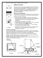
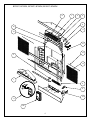
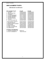
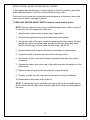
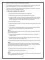
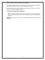
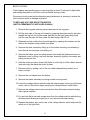
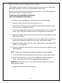
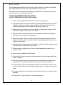
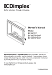
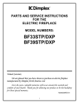
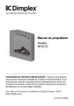
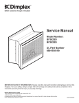
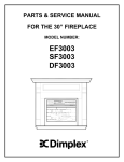
PARTS & SERVICE MANUAL
FOR THE BUILT IN FIREPLACE
MODEL NUMBERS:
BF33ST/DX
BF39ST/DX
BF45ST/DX
TABLE OF CONTENTS
OPERATION
PAGE 1
VOLTAGE SELECTOR SWITCH LOCATION
PAGE 3
PARTS LIST DRAWING
PAGE 4
PARTS LIST
PAGE 5
WIRING DIAGRAM – LOWER SECTION
PAGE 7
WIRING DIAGRAM – UPPER SECTION
PAGE 8
WIRING DIAGRAM – SCHEMATIC
PAGE 9
LIGHT BULB REPLACEMENT
PAGE 10
MAIN ON/OFF SWITCH REPLACEMENT
PAGE 11
HEATER ON/OFF SWITCH REPLACEMENT
PAGE 12
FLAME MOTOR/FLAME ROD REPLACEMENT
PAGE 13
VOLTAGE SELECTOR SWITCH REPLACEMENT
(UNIT IS PERMENANTLY INSTALLED IN WALL)
BF33ST, BF33DX
BF39ST, BF39DX, BF45ST, BF45DX
PAGE 15
PAGE 17
VOLTAGE SELECTOR SWITCH REPLACEMENT
(UNIT CAN BE REMOVED FROM WALL)
PAGE 19
HEATING ELEMENTS REPLACEMENT
(UNIT IS PERMENANTLY INSTALLED IN WALL)
PAGE 20
HEATING ELEMENTS REPLACEMENT
(UNIT CAN BE REMOVED FROM WALL)
PAGE 21
BLOWER MOTOR/BLOWER REPLACEMENT
(UNIT IS PERMENANTLY INSTALLED IN WALL)
BF33ST, BF33DX
BF39ST, BF39DX, BF45ST, BF45DX
PAGE 22
PAGE 24
BLOWER MOTOR/BLOWER REPLACEMENT
(UNIT CAN BE REMOVED FROM WALL)
PAGE 25
TEMPERATURE LIMIT SWITCH REPLACEMENT
(UNIT IS PERMENANTLY INSTALLED IN WALL)
BF33ST, BF33DX
BF39ST, BF39DX, BF45ST, BF45DX
PAGE 26
PAGE 28
TEMPERATURE LIMIT SWITCH REPLACEMENT
(UNIT CAN BE REMOVED FROM WALL)
PAGE 30
REMOTE CONTROL KIT REPLACEMENT
PAGE 31
BF33ST, BF33DX, BF39ST, BF39DX, BF45ST, BF45DX
OPERATION
MANUAL CONTROLS
(WITHOUT REMOTE OPTION)
The fireplace can be controlled by the manual
switches located on the fireplace (FIGURE 1).
Main Power Switch
Main ON/OFF switch, activates the flame effect.
Heater Control Switch
Heater ON/OFF switch, activates heater to the high
level.
MANUAL CONTROLS
(WITH REMOTE OPTION)
HEATER CONTROL
SWITCH
MAIN POWER
SWITCH
The fireplace can also be controlled in a similar
manner to the remote control with the manual
switches located on the fireplace (FIGURE 2).
(refer to initialization instructions on page 2)
Main Power Switch
Main ON/OFF switch supplies power to the circuit
board. When the Main ON/OFF switch is switched to
the ON position the Level 1 indicator light will flash.
FIGURE 1
OFF
SWITCH
On Switch
1. Pressing once on the remote control board “ON
SWITCH” activates the Level 1 function.
Level 1: The flame effect is turned on and the first
MAIN POWER
red indicator light is activated.
SWITCH
2. Pressing twice on the remote control board “ON
SWITCH” activates the Level 2 function.
Level 2: The flame effect remains on, the heater
is activated to the low heat setting, and
the first and second red indicator lights are
activated.
ON
SWITCH
LEVEL 3
INDICATOR
LEVEL 1
INDICATOR
LEVEL 2
INDICATOR
3. Pressing three times on the remote control board
“ON SWITCH” activates the Level 3 function.
Level 3: The flame effect remains on, the heater
is set to the high heat setting, and all three red
indicator lights are activated.
Off Switch
Pressing this button ONCE will turn the unit OFF.
FIGURE 2
1
BF33ST, BF33DX, BF39ST, BF39DX, BF45ST, BF45DX
REMOTE CONTROL
The remote control has a range of approximately 50ft. (15.25m). It
does not have to be pointed at the fireplace and can pass through
most obstacles (including walls). It is supplied with one of 243
independent frequencies to prevent interference with other units.
The frequency designation is indicated on the back of the
transmitter (FIGURE 3).
Remote Control Initialization
This procedure is required every time there is a loss of power to the
remote control in the fireplace (i.e. power failure, breaker tripped,
main power switch is turned off)
1. Ensure that power is supplied through main service panel.
2. Access the manual controls, (remove glass doors if applicable)
pull the right hand steel curtain to the side of the unit.
(FIGURE 4)
3. Locate manual controls refer to FIGURE 5.
4. Activate main power switch, (“ ” position is “ON”, “ ” position
is “OFF”) red Level 1 indicator light will flash.
Frequency 5. Press and hold the ON switch marked “ ” for five seconds.
Code
The red Level 2 indicator light will flash.
6. Press the ON button located on the remote control transmitter
(FIGURE 3). This will synchronize the remote control
FIGURE 3
transmitter and receiver.
Remote Control Usage
The remote control operates the fireplace levels sequentially. The level is increased
every time the ON button on the transmitter is pressed. The fireplace can be turned off
at any point by pressing the OFF button on the remote control transmitter.
Level 1: The flame effect is turned on and the first red indicator light is activated.
Level 2: The flame effect remains on, the heater is activated to the low heat setting,
and the first and second red indicator lights are activated.
Level 3: The flame effect remains on, the heater is set to the high heat setting, and all
three red indicator lights are activated.
MANUAL
CONTROLS
Off Switch
On Switch
FIGURE 4
Level 1 Indicator
2
Main Power
Switch
Level 3 Indicator
Level 2 Indicator
FIGURE 5
BF33ST, BF33DX, BF39ST, BF39DX, BF45ST, BF45DX
RESETTING THE TEMPERTURE CUTOUT SWITCH
The heater on this fireplace is protected with a safety device to prevent overheating.
Should the heater overheat, an automatic cut out will turn the heater off and it will not
come back on without being reset. It can be reset by switching the Main Power switch
(FIGURE 1) to OFF and waiting 5 minutes before switching it to ON.
WALL MOUNTED CONTROLS
The fireplace can be installed with wall mounted controls. These controls include wall
switches and thermostats. (see installation guide for details)
A. Wall Mounted Switches
This model may be installed such that a wall mounted switch activates the flame effect
and a wall mounted heater switch activates the heater. A wall mounted switch can also
be installed to operate the heater independent of the flame.
B. Wall Mounted Thermostat
This unit may be installed such that a wall mounted thermostat can adjust the heat
temperature to your individual requirements. Turn the thermostat control clockwise all
the way to turn on the heater. When the room reaches the desired temperature, turn
the thermostat knob counter clockwise until you hear a click. Leave in this position to
maintain the room temperature at this setting. For additional heat, turn the thermostat
clockwise until you hear the click again and the heater will turn on. To turn the heater
off, turn the thermostat counter clockwise all the way, and/or turn the manual heater
switch on the unit to the OFF position.
VOLTAGE SELECTOR SWITCH LOCATION
IMPORTANT:
Ensure that the incoming power supply voltage
matches the setting of the voltage selector
switch.
NOTE:
The voltage selector switch is located
inside the exhaust panel on the top
right hand corner (FIGURE 6).
CAUTION:
When changing the voltage selector
switch from 240 volts to 120 volts
ensure that the power supply is turned
off.
FIGURE 6
NOTE:
Carefully insert a flat headed screwdriver inside the exhaust panel to change the switch
from 240 volts (230 position) to 120 volts (115 position).
3
BF33ST, BF33DX, BF39ST, BF39DX, BF45ST, BF45DX
8
7
5
6
9
12
11
13
10
15
3
14
1
2
4
16
17
18
4
BF33ST, BF33DX, BF39ST, BF39DX
REPLACEMENT PARTS
DIMPLEX BUILT IN FIREPLACE
REPLACEMENT PART
1. LOG SET
2. REFLECTOR ROD
3. GROMMET
4. FLICKER ASSEMBLY
5. BLOWER ASSEMBLY
6. BLOWER MOTOR
7. HEATER ELEMENT
8. CUTOUT
9. VOLTAGE SELECTOR
10. MAIN ON/OFF SWITCH
11. HEATER SWITCH
12. MIRROR SEMI-SILVERED
13. EXTRUSION
14. STEEL CURTAIN
15. STEEL CURTAIN ROD
16. LAMPHOLDER
BF33ST
0438200300RP
5900081000RP
8500000600RP
6901811200RP
5300110300RP
5300110400RP
2200510100RP
2300200400RP
2500320100RP
2800070400RP
2800070700RP
5900161000RP
0438650200RP
8800240403RP
8800250300RP
4200120700RP
OPTIONAL ACCESSORIES
17. REMOTE CONTROL KIT
18. WALL THERMOSTAT
BFRC-KIT
TS901/TS901W
REPLACEMENT PART
1. LOG SET
2. REFLECTOR ROD
3. GROMMET
4. FLICKER ASSEMBLY
5. BLOWER ASSEMBLY
6. BLOWER MOTOR
7. HEATER ELEMENT
8. CUTOUT
9. VOLTAGE SELECTOR
10. MAIN ON/OFF SWITCH
11. HEATER SWITCH
12. MIRROR SEMI-SILVERED
13. EXTRUSION
14. STEEL CURTAIN
15. STEEL CURTAIN ROD
16. LAMPHOLDER
BF39ST
0438550200RP
5900080900RP
8500000600RP
6901811200RP
5300110300RP
5300110400RP
2200510100RP
2300200400RP
2500320100RP
2800070400RP
2800070700RP
5900160600RP
0438650100RP
8800240103RP
8800250100RP
4200120700RP
OPTIONAL ACCESSORIES
17. REMOTE CONTROL KIT
18. WALL THERMOSTAT
BFRC-KIT
TS901/TS901W
5
BF33DX
0438200300RP
5900081000RP
8500000600RP
6901811200RP
5300110300RP
5300110400RP
2200510100RP
2300200400RP
2500320100RP
2800070400RP
2800070700RP
5900161100RP
0438650200RP
8800240403RP
8800250300RP
4200120700RP
BF39DX
0438550200RP
5900080900RP
8500000600RP
6901811200RP
5300110300RP
5300110400RP
2200510100RP
2300200400RP
2500320100RP
2800070400RP
2800070700RP
5900160700RP
0438650100RP
8800240103RP
8800250200RP
4200120700RP
BF45ST, BF45DX
REPLACEMENT PARTS
DIMPLEX BUILT IN FIREPLACE
REPLACEMENT PART
1. LOG SET
2. REFLECTOR ROD
3. GROMMET
4. FLICKER ASSEMBLY
5. BLOWER ASSEMBLY
6. BLOWER MOTOR
7. HEATER ELEMENT
8. CUTOUT
9. VOLTAGE SELECTOR
10. MAIN ON/OFF SWITCH
11. HEATER SWITCH
12. MIRROR SEMI-SILVERED
13. EXTRUSION
14. STEEL CURTAIN
15. STEEL CURTAIN ROD
16. LAMPHOLDER
BF45ST
0438550200RP
5900080900RP
8500000600RP
6901811200RP
5300110300RP
5300110400RP
2200510100RP
2300200400RP
2500320100RP
2800070400RP
2800070700RP
5900160800RP
0438650100RP
8800240203RP
8800250200RP
4200120700RP
OPTIONAL ACCESSORIES
17. REMOTE CONTROL KIT
18. WALL THERMOSTAT
BFRC-KIT
TS901/TS901W
6
BF45DX
0438550200RP
5900080900RP
8500000600RP
6901811200RP
5300110300RP
5300110400RP
2200510100RP
2300200400RP
2500320100RP
2800070400RR
2800070700RP
5900160400RP
0438650100RP
8800240203RP
8800250200RP
4200120700RP
BF33ST, BF33DX, BF39ST, BF39DX, BF45ST, BF45DX
WIRING DIAGRAM - LOWER SECTION
WHITE
BLUE
1A
5B
2A
G
4B
GREEN
RED (L2)
BLACK (L1)
WHITE (N)
TWIST-TIE
2
HEATER SWITCH
1
BYPASS HARNESS
RED
BLACK (L1)
BROWN FROM TOP
RED FROM TOP
WHITE (N)
ORANGE FROM TOP
RED
RED (L2)
LOWER HARNESS
BLACK
MAIN
SWITCH
MARR
WHITE
7
RED (2)
RED (1)
BLUE (4)
MARR
BLUE (3)
WHITE
CAPACITOR
WHITE
BLACK
FLICKER
MOTOR
BROWN
BLACK
BF33ST, BF33DX, BF39ST, BF39DX, BF45ST, BF45DX
WIRING DIAGRAM - UPPER SECTION
BROWN
ORANGE
RED (CUT-OUT LONG WIRE)
BLK
5
3
1
6
4
2
YLW
BLK
BLW.
MOTOR
BLK
YLW
BLK
BLOWER WHEEL
ELEMENT #1
ELEMENT #2
RED (CUT-OUT SHORT WIRE)
CUT-OUT
BLK
YLW
8
BLK
BF33ST, BF33DX, BF39ST, BF39DX, BF45ST, BF45DX
WIRING DIAGRAM - SCHEMATIC
9
BF33ST, BF33DX, BF39ST, BF39DX, BF45ST, BF45DX
If unit was operating prior to servicing allow at least 10 minutes for light bulbs and
heating element to cool off to avoid accidental burning of skin.
Disconnect power before attempting any maintenance or cleaning to reduce the risk of
electric shock or damage to persons.
Light bulbs need to be replaced when you notice a dark section of the flame. There are
four bulbs under the log set which generate the flames and embers.
It is a good idea to replace all of the light bulbs at one time if they are close to the end of
their rated life. Group replacement will reduce the number of times you need to open
the unit to replace the light bulbs.
TO REPLACE LIGHT BULBS
1. Open the steel curtains (remove glass doors if applicable).
2. Remove the log grate retaining screws and remove the log grate.
3. Pull the rear edge of the log set forward by grasping the ember bed by the sides
(handle the log set only by the ember bed and not the logs) and pulling firmly
until the rear tab pops out from under the back ledge, then lift out.
4. Examine to determine which bulbs require replacement.
5. Unscrew bulb counter clockwise.
6. Insert new bulb screwing clockwise.
7. Replace the log set by inserting the front edge, pushing the back down until the
rear tab snaps under the back ledge and the logs are resting against the mirror.
Quantity 4 clear chandelier or candelabra bulbs with an E-12 (small) socket
base, 60 watt rating. Example GE 60BC or Philips 60CTC
CAUTION DO NOT EXCEED 60 WATTS PER BULB
10
BF33ST, BF33DX, BF39ST, BF39DX, BF45ST, BF45DX
If the fireplace was operating prior to servicing allow at least 10 minutes for light bulbs
and heating elements to cool off to avoid accidental burning of skin.
Disconnect circuit power before attempting any maintenance or cleaning to reduce the
risk of electric shock or damage to persons.
TO REPLACE MAIN ON/OFF SWITCH
1. Open the steel curtains (remove glass doors if applicable).
2. Remove the log grate retaining screws and remove the log grate.
3. Pull the rear edge of the log set forward by grasping the ember bed by the sides
(handle the log set only by the ember bed and not the logs) and pulling firmly
until the rear tab pops out from under the back ledge, then lift out.
4. Remove the light bulb closest to the main on/off switch for easier access.
5. Locate the switch cover plate and remove the mounting screws.
6. Remove the switch cover plate by releasing assembly from the quick connect
connection.
7. Reach hand into the opening and locate the main on/off switch.
8. Depress the retainer clips on the rear of the switch and push the switch out of the
bottom cover.
9. Disconnect the wiring connections noting their original locations.
10. Properly orientate the new switch and connect all of the wiring connections.
11. Reassemble in the reverse order as above.
NOTE: To replace the log set insert the front edge, pushing back down until the rear
tab snaps under the back ledge and the logs are resting against the mirror.
11
BF33ST, BF33DX, BF39ST, BF39DX, BF45ST, BF45DX
If the fireplace was operating prior to servicing allow at least 10 minutes for light bulbs
and heating elements to cool off to avoid accidental burning of skin.
Disconnect circuit power before attempting any maintenance or cleaning to reduce the
risk of electric shock or damage to persons.
TO REPLACE HEATER ON/OFF SWITCH (without remote control option)
NOTE: Remote control kit does not have individual heater switch. Refer to page 27
for remote control kit replacement instructions.
1. Open the steel curtains (remove glass doors if applicable).
2. Remove the log grate retaining screws and remove the log grate.
3. Pull the rear edge of the log set forward by grasping the ember bed by the sides
(handle the log set only by the ember bed and not the logs) and pulling firmly
until the rear tab pops out from under the back ledge, then lift out.
4. Remove the light bulb closest to the heater on/off switch for easier access.
5. Locate the switch cover plate and remove the mounting screws.
6. Remove the switch cover plate by releasing assembly from the quick connect
connection.
7. Depress the retainer clips on the rear of the switch and push the switch out of the
bottom cover.
8. Disconnect the wiring connections noting their original locations.
9. Properly orientate the new switch and connect all of the wiring connections.
10. Reassemble in the reverse order as above.
NOTE: To replace the log set, insert the front edge of the log set and pushing back
down until the rear tab snaps under the back ledge and the logs are resting against
the mirror.
12
BF33ST, BF33DX, BF39ST, BF39DX, BF45ST, BF45DX
If the fireplace was operating prior to servicing allow at least 10 minutes for light bulbs
and heating elements to cool off to avoid accidental burning of skin.
Disconnect circuit power before attempting any maintenance or cleaning to reduce the
risk of electric shock or damage to persons.
TO REPLACE FLAME MOTOR/FLAME ROD
1. Open the steel curtains (remove glass doors if applicable).
2. Remove the log grate retaining screws and remove the log grate.
3. Pull the rear edge of the log set forward by grasping the ember bed by the sides
(handle the log set only by the ember bed and not the logs) and pulling firmly
until the rear tab pops out from under the back ledge, then lift out.
4. Remove all lower light bulbs.
5. Remove the retaining screws on the light assembly retaining plate and set aside
retaining plate.
6. Reach hand into the opening created by removing the light assembly retaining
plate and locate the flame assembly mounting bracket screw.
NOTE:
Flame assembly bracket screw is secured to flame panel on the same side as the
manual control switches.
7. Remove the flame assembly mounting bracket screw using a ¼” hex head
wrench or socket.
8. Remove the flame rod from the flame assembly by pulling the rubber channel
section of the rod away from the flame motor.
9. Rotate the flame assembly down releasing the mounting tab from the rear panel.
NOTE:
In order for the mounting tab to release from the rear panel, the flame assembly
mounting bracket needs to be rotated a complete 90° down. Cutting of the wire tie
wraps may be required to move wires out of the way.
10. Disconnect the wiring connections noting their original locations.
11. Reassemble in the reverse order as above.
NOTE:
Ensure to secure the flame rod to the end of the flame motor prior to securing flame
motor assembly bracket to flame panel.
13
BF33ST, BF33DX, BF39ST, BF39DX, BF45ST, BF45DX
If the fireplace was operating prior to servicing allow at least 10 minutes for light bulbs
and heating elements to cool off to avoid accidental burning of skin.
Disconnect circuit power before attempting any maintenance or cleaning to reduce the
risk of electric shock or damage to persons.
TO REPLACE FLAME MOTOR/FLAME ROD
NOTE: To replace the log set, insert the front edge of the log set and pushing back
down until the rear tab snaps under the back ledge and the logs are resting against
the mirror.
WARNING: Ensure wires do not come in contact with moving parts by securing wires in
wire wraps.
14
BF33ST, BF33DX
If the fireplace was operating prior to servicing allow at least 10 minutes for light bulbs
and heating elements to cool off to avoid accidental burning of skin.
Disconnect circuit power before attempting any maintenance or cleaning to reduce the
risk of electric shock or damage to persons.
TO REPLACE VOLTAGE SELECTOR SWITCH
(UNIT IS PERMENANTLY INSTALLED IN WALL)
1. Remove the log grate retaining screws and remove the log grate.
2. Pull the rear edge of the log set forward by grasping the ember bed by the sides
(handle the log set only by the ember bed and not the logs) and pulling firmly
until the rear tab pops out from under the back ledge, then lift out.
3. Release the steel curtains from the side panels by opening the retainers on the
sides of the fireplace using needle nose pliers.
4. Remove the steel curtains by lifting up on the curtain mounting rod releasing it
from the side mounting tab, and pulling out.
5. Remove the heater cover mounting screws from inside the firebox and remove
the heater cover by lifting it up from the back, bowing it slightly in the center and
pulling out by one end.
6. Hold the mirror and use a sharp utility knife to cut the lip off of the rubber channel
(one side only) that holds the mirror in place.
7. Remove mirror by pulling it out of the cut rubber channel being careful not to
bump or drop it.
8. Remove the cut channel from the firebox.
9. Remove the heater assembly mounting screws from top panel.
10. Locate the voltage selector switch inside the exhaust panel on the top right hand
corner, and cut the wire tie wraps securing the voltage selector switch wires.
11. Remove the voltage selector wire connections from the heater elements noting
their original locations.
12. Cut and strip the brown and orange wires from the voltage selector switch along
the back panel allowing enough room to cut, strip and reconnect wiring.
13. Depress the retainer clips on the rear of the voltage selector switch and push the
switch out of the light block.
15
BF33ST, BF33DX
If the fireplace was operating prior to servicing allow at least 10 minutes for light bulbs
and heating elements to cool off to avoid accidental burning of skin.
Disconnect circuit power before attempting any maintenance or cleaning to reduce the
risk of electric shock or damage to persons.
TO REPLACE VOLTAGE SELECTOR SWITCH
(UNIT IS PERMENANTLY INSTALLED IN WALL)
14. Properly orientate the new switch and connect all of the wiring connections to the
heater elements.
NOTE: Ensure there is enough wire length to wire connect the wires together.
15. Cut and strip the brown and orange wires from the new voltage selector switch.
16. Use (2) wire connectors to connect the 4 stripped wire with their matching colour.
(brown wire with brown wire, orange wire with orange wire)
WARNING: Ensure wires do not come in contact with moving parts by securing
wires in wiring tie wraps.
17. Using a sharp utility knife, cut 3.22” off of the length of the new rubber channel so
the overall length is 17.33”.
18. Reassemble in the reverse order as above.
NOTE: Prior to installing the mirror, cut the one end off of the T-shaped groove on
the supplied rubber channel with a sharp utility knife as indicated in diagram below.
Remove the shaded area
from rubber channel with
sharp utility knife
NOTE: To install the mirror after the factory installed rubber channel has been cut,
use the channel that was supplied with the replacement motor / blower. Slide the
channel onto the edge of the mirror and push the other side of the mirror into the
existing rubber channel in the firebox, carefully press mirror into the mounting slot on
the firebox.
NOTE: To replace the log set insert the front edge, pushing back down until the rear
tab snaps under the back ledge and the logs are resting against the mirror.
16
BF39ST, BF39DX, BF45ST, BF45DX
If the fireplace was operating prior to servicing allow at least 10 minutes for light bulbs
and heating elements to cool off to avoid accidental burning of skin.
Disconnect circuit power before attempting any maintenance or cleaning to reduce the
risk of electric shock or damage to persons.
TO REPLACE VOLTAGE SELECTOR SWITCH
(UNIT IS PERMENANTLY INSTALLED IN WALL)
1. Remove the log grate retaining screws and remove the log grate.
2. Pull the rear edge of the log set forward by grasping the ember bed by the sides
(handle the log set only by the ember bed and not the logs) and pulling firmly
until the rear tab pops out from under the back ledge, then lift out.
3. Release the steel curtains from the side panels by opening the retainers on the
sides of the fireplace using needle nose pliers.
4. Remove the steel curtains by lifting up on the curtain mounting rod releasing it
from the side mounting tab, and pulling out.
5. Remove the heater cover mounting screws from inside the firebox and remove
the heater cover by lifting it up from the back, bowing it slightly in the center and
pulling out by one end.
6. Locate the voltage selector switch inside the exhaust panel on the top right hand
corner, and cut wire the tie wraps securing the voltage selector switch wires.
7. Remove the voltage selector wire connections from the heater elements noting
their original locations.
8. Cut and strip the brown and orange wires from the voltage selector switch along
the back panel allowing enough room to cut, strip and reconnect wiring.
9. Depress the retainer clips on the rear of the voltage selector switch and push the
switch out of the light block.
10. Properly orientate the new switch and connect all of the wiring connections to the
heater elements
NOTE: Ensure there is enough wire length to wire connect the wires together.
11. Cut and strip the brown and orange wires from the new voltage selector switch.
17
BF39ST, BF39DX, BF45ST, BF45DX
If the fireplace was operating prior to servicing allow at least 10 minutes for light bulbs
and heating elements to cool off to avoid accidental burning of skin.
Disconnect circuit power before attempting any maintenance or cleaning to reduce the
risk of electric shock or damage to persons.
TO REPLACE VOLTAGE SELECTOR SWITCH
(UNIT IS PERMENANTLY INSTALLED IN WALL)
12. Use (2) wire connectors to connect the 4 stripped wires with matching colour.
(brown wire with brown wire, orange wire with orange wire)
WARNING: Ensure wires do not come in contact with moving parts by securing
wires in wiring tie wraps.
13. Reassemble in the reverse order as above.
NOTE: To replace the log set insert the front edge, pushing back down until the rear
tab snaps under the back ledge and the logs are resting against the mirror.
18
BF33ST, BF33DX, BF39ST, BF39DX, BF45ST, BF45DX
If the fireplace was operating prior to servicing allow at least 10 minutes for light bulbs
and heating elements to cool off to avoid accidental burning of skin.
Disconnect circuit power before attempting any maintenance or cleaning to reduce the
risk of electric shock or damage to persons.
TO REPLACE VOLTAGE SELECTOR SWITCH
(UNIT CAN BE REMOVED FROM WALL)
1. Remove unit from installed wall. (remove trim surround if applicable)
2. Remove a total of 4 screws from both side trims on unit.
3. Remove the 6 top panel mounting screws and position heater assembly upright
being careful not to damage any wires.
4. Locate the voltage selector switch inside the exhaust panel on the top right hand
corner, and cut the wire tie wraps securing the voltage selector switch wires.
5. Disconnect voltage selector switch wire connections from heater elements noting
their original locations.
6. Cut and strip the brown and orange wires from the voltage selector switch along
the back panel allowing enough room to cut, strip, and reconnect wiring.
7. Depress the retainer clips on the rear of the voltage selector switch and push the
switch out of the light block.
8. Properly orientate the new switch and connect all of the wiring connections to the
heater elements.
NOTE: Ensure there is enough wire length to wire connect the wires together.
9. Cut and strip the brown and orange wires from the new voltage selector switch.
10. Use (2) wire connectors to connect the 4 stripped wires with their matching
colour. (brown wire with brown wire, orange wire with orange wire)
WARNING: Ensure wires do not come in contact with moving parts by securing
wires in wiring tie wraps.
11. Reassemble in the reverse order as above.
19
BF33ST, BF33DX, BF39ST, BF39DX, BF45ST, BF45DX
If the fireplace was operating prior to servicing allow at least 10 minutes for light bulbs
and heating elements to cool off to avoid accidental burning of skin.
Disconnect circuit power before attempting any maintenance or cleaning to reduce the
risk of electric shock or damage to persons.
TO REPLACE HEATING ELEMENTS
(UNIT IS PERMENANTLY INSTALLED IN WALL)
NOTE: The fireplace is equipped with two heating elements. The same removal &
installation instructions apply to both elements.
1. Remove the log grate retaining screws and remove the log grate.
2. Pull the rear edge of the log set forward by grasping the ember bed by the sides
(handle the log set only by the ember bed and not the logs) and pulling firmly
until the rear tab pops out from under the back ledge, then lift out.
3. Release the steel curtains from the side panels by opening the retainers on the
sides of the fireplace using needle nose pliers.
4. Remove the steel curtains by lifting up on the curtain mounting rod releasing it
from the side mounting tab, and pulling out.
5. Remove the heater cover mounting screws from inside the firebox and remove
the heater cover by lifting it up from the back, bowing it slightly in the center and
pulling out by one end.
6. Locate the elements mounted to the top cover and disconnect the connections
noting their original locations.
7. Remove the 2 element cover hex head screws using a ⅜” hex head socket.
8. Remove the 3 remaining element cover mounting screws and remove element.
9. Properly orientate the replacement element and connect all of the wiring
connections in their original locations.
10. Reassemble in the reverse order as above.
NOTE: To replace the log set insert the front edge, pushing back down until the rear
tab snaps under the back ledge and the logs are resting against the mirror.
20
BF33ST, BF33DX, BF39ST, BF39DX, BF45ST, BF45DX
If the fireplace was operating prior to servicing allow at least 10 minutes for light bulbs
and heating elements to cool off to avoid accidental burning of skin.
Disconnect circuit power before attempting any maintenance or cleaning to reduce the
risk of electric shock or damage to persons.
TO REPLACE HEATING ELEMENTS
(UNIT CAN BE REMOVED FROM WALL)
NOTE: The fireplace is equipped with two heating elements. The same removal &
installation instructions apply to both elements.
1. Remove unit from installed wall. (remove trim surround if applicable)
2. Remove a total of 4 screws from both side trims on unit.
3. Remove top panel mounting screws and position heater assembly upright being
careful not to damage any wires.
4. Locate the elements mounted to the top cover and disconnect the connections
noting their original locations.
5. Remove the 2 element cover hex head screws using a ⅜” hex head socket.
6. Remove the 3 remaining element cover mounting screws and remove element.
7. Properly orientate the replacement element and connect all of the wiring
connections in their original locations.
8. Reassemble in the reverse order as above.
21
BF33ST, BF33DX
If the fireplace was operating prior to servicing allow at least 10 minutes for light bulbs
and heating elements to cool off to avoid accidental burning of skin.
Disconnect circuit power before attempting any maintenance or cleaning to reduce the
risk of electric shock or damage to persons.
TO REPLACE BLOWER MOTOR / BLOWER
(UNIT IS PERMENANTLY INSTALLED IN WALL)
1. Remove the log grate retaining screws and remove the log grate.
2. Pull the rear edge of the log set forward by grasping the ember bed by the sides
(handle the log set only by the ember bed and not the logs) and pulling firmly
until the rear tab pops out from under the back ledge, then lift out.
3. Release the steel curtains from the side panels by opening the retainers on the
sides of the fireplace using needle nose pliers.
4. Remove the steel curtains by lifting up on the curtain mounting rod releasing it
from the side mounting tab, and pulling out.
5. Remove the heater cover mounting screws from inside the firebox and remove
the heater cover by lifting it up from the back, bowing it slightly in the center and
pulling out by one end.
NOTE: A new rubber channel that holds the mirror in place is supplied with the new
blower motor.
6. Hold the mirror and use a sharp utility knife to cut the lip off of the rubber channel
(one side only) that holds the mirror in place.
7. Remove mirror by pulling it out of the cut rubber channel being careful not to
bump or drop it.
8. Remove the cut channel from the firebox.
9. Remove the (3) heater assembly mounting screws from top panel.
10. Lower heater assembly and remove wiring connections from blower motor noting
their original locations.
11. Remove the (6) blower motor assembly screws and set aside blower motor
assembly.
12. Properly orientate the replacement blower assembly and connect all of the wiring
connections in their original locations.
13. Using a sharp utility knife, cut 3.22” off of the length of the rubber channel so the
overall length is 17.33”.
22
BF33ST, BF33DX
If the fireplace was operating prior to servicing allow at least 10 minutes for light bulbs
and heating elements to cool off to avoid accidental burning of skin.
Disconnect circuit power before attempting any maintenance or cleaning to reduce the
risk of electric shock or damage to persons.
TO REPLACE BLOWER MOTOR / BLOWER
(UNIT IS PERMENANTLY INSTALLED IN WALL)
14. Reassemble in the reverse order as above.
NOTE: Prior to installing the mirror, cut the one end off of the T-shaped groove on
the supplied rubber channel with a sharp utility knife as indicated in diagram below.
Remove the shaded area
from rubber channel with
sharp utility knife
NOTE: To install the mirror after the factory installed rubber channel has been cut,
use the channel that was supplied with the replacement motor / blower. Slide the
channel onto the edge of the mirror and push the other side of the mirror into the
existing rubber channel in the firebox, carefully press mirror into the mounting slot on
the firebox.
NOTE: To replace the log set insert the front edge, pushing back down until the rear
tab snaps under the back ledge and the logs are resting against the mirror.
23
BF39ST, BF39DX, BF45ST, BF45DX
If the fireplace was operating prior to servicing allow at least 10 minutes for light bulbs
and heating elements to cool off to avoid accidental burning of skin.
Disconnect circuit power before attempting any maintenance or cleaning to reduce the
risk of electric shock or damage to persons.
TO REPLACE BLOWER MOTOR / BLOWER
(UNIT IS PERMENANTLY INSTALLED IN WALL)
1. Remove the log grate retaining screws and remove the log grate.
2. Pull the rear edge of the log set forward by grasping the ember bed by the sides
(handle the log set only by the ember bed and not the logs) and pulling firmly
until the rear tab pops out from under the back ledge, then lift out.
3. Release the steel curtains from the side panels by opening the retainers on the
sides of the fireplace using needle nose pliers.
4. Remove the steel curtains by lifting up on the curtain mounting rod releasing it
from the side mounting tab, and pulling out.
5. Remove the heater cover mounting screws from inside the firebox and remove
the heater cover by lifting it up from the back, bowing it slightly in the center and
pulling out by one end.
6. Remove the (3) heater assembly mounting screws from top panel.
7. Lower heater assembly and remove wiring connections from blower motor noting
their original locations.
8. Remove the (6) blower motor assembly screws and set aside blower motor
assembly.
9. Properly orientate the replacement blower assembly and connect all of the wiring
connections in their original locations.
10. Reassemble in the reverse order as above.
NOTE: To replace the log set insert the front edge, pushing back down until the
rear tab snaps under the back ledge and the logs are resting against the mirror.
24
BF33ST, BF33DX, BF39ST, BF39DX, BF45ST, BF45DX
If the fireplace was operating prior to servicing allow at least 10 minutes for light bulbs
and heating elements to cool off to avoid accidental burning of skin.
Disconnect circuit power before attempting any maintenance or cleaning to reduce the
risk of electric shock or damage to persons.
TO REPLACE BLOWER MOTOR / BLOWER
(UNIT CAN BE REMOVED FROM WALL)
1. Remove unit from installed wall. (remove trim surround if applicable)
2. Locate and remove both side trims from unit.
3. Remove top panel mounting screws and position heater assembly upright being
careful not to damage any wires.
4. Remove the (3) heater assembly mounting screws from top panel.
5. Remove the (6) blower motor assembly screws and set aside blower motor
assembly.
6. Properly orientate the replacement blower assembly and connect all of the wiring
connections in their original locations.
7. Reassemble in the reverse order as above.
25
BF33ST, BF33DX
If the fireplace was operating prior to servicing allow at least 10 minutes for light bulbs
and heating elements to cool off to avoid accidental burning of skin.
Disconnect circuit power before attempting any maintenance or cleaning to reduce the
risk of electric shock or damage to persons.
TO REPLACE TEMPERATURE LIMIT SWITCH
(UNIT IS PERMENANTLY INSTALLED IN WALL)
1. Remove the log grate retaining screws and remove the log grate.
2. Pull the rear edge of the log set forward by grasping the ember bed by the sides
(handle the log set only by the ember bed and not the logs) and pulling firmly
until the rear tab pops out from under the back ledge, then lift out.
3. Release the steel curtains from the side panels by opening the retainers on the
sides of the fireplace using needle nose pliers.
4. Remove the steel curtains by lifting up on the curtain mounting rod releasing it
from the side mounting tab, and pulling out.
5. Remove the heater cover mounting screws from inside the firebox and remove
the heater cover by lifting it up from the back, bowing it slightly in the center and
pulling out by one end.
6. Hold the mirror and use a sharp utility knife to cut the lip off of the rubber channel
(one side only) that holds the mirror in place.
7. Remove mirror by pulling it out of the cut rubber channel being careful not to
bump or drop it.
8. Remove the cut channel from the firebox.
9. Remove the (3) heater assembly mounting screws from the top panel and lower
heater assembly.
10. Remove the temperature limit switch screw from heater bracket assembly and
disconnect the (1) temperature limit switch wire from the heater element.
11. Cut and strip the (1) other remaining temperature limit switch wire end with wire
cutters closest to blower motor allowing enough room to cut, strip and reconnect
wiring.
12. Properly orientate the new temperature limit switch and secure to heater bracket
assembly.
13. Connect the (1) wire connection to the heating element.
26
BF33ST, BF33DX
If the fireplace was operating prior to servicing allow at least 10 minutes for light bulbs
and heating elements to cool off to avoid accidental burning of skin.
Disconnect circuit power before attempting any maintenance or cleaning to reduce the
risk of electric shock or damage to persons.
TO REPLACE TEMPERATURE LIMIT SWITCH
(UNIT IS PERMENANTLY INSTALLED IN WALL)
14. Cut and strip the remaining temperature limit switch wire and wire connect, with
wire connector, to the other stripped cutout wire.
15. Reassemble in the reverse order as above.
WARNING: Ensure wires do not come in contact with moving parts by securing
wires in tie wraps.
NOTE: Prior to installing the mirror, cut the one end off of the T-shaped groove on
the rubber channel with a sharp utility knife as indicated in diagram below.
Remove the shaded area
from rubber channel with
sharp utility knife
NOTE: To install the mirror after the factory installed rubber channel has been cut,
use the channel that was supplied with the replacement motor / blower. Slide the
channel onto the edge of the mirror and push the other side of the mirror into the
existing rubber channel in the firebox, carefully press mirror into the mounting slot on
the firebox.
NOTE: To replace the log set insert the front edge, pushing back down until the rear
tab snaps under the back ledge and the logs are resting against the mirror.
27
BF39ST, BF39DX, BF45ST, BF45DX
If the fireplace was operating prior to servicing allow at least 10 minutes for light bulbs
and heating elements to cool off to avoid accidental burning of skin.
Disconnect circuit power before attempting any maintenance or cleaning to reduce the
risk of electric shock or damage to persons.
TO REPLACE TEMPERATURE LIMIT SWITCH
(UNIT IS PERMENANTLY INSTALLED IN WALL)
1. Remove the log grate retaining screws and remove the log grate.
2. Pull the rear edge of the log set forward by grasping the ember bed by the sides
(handle the log set only by the ember bed and not the logs) and pulling firmly until
the rear tab pops out from under the back ledge, then lift out.
3. Release the steel curtains from the side panels by opening the retainers on the sides
of the fireplace using needle nose pliers.
4. Remove the steel curtains by lifting up on the curtain mounting rod releasing it from
the side mounting tab, and pulling out.
5. Remove the heater cover mounting screws from inside the firebox and remove the
heater cover by lifting it up from the back, bowing it slightly in the center and pulling
out by one end.
6. Remove the (3) heater assembly mounting screws from the top panel and lower
heater assembly.
7. Remove temperature limit switch screw from heater bracket assembly and
disconnect the (1) temperature limit switch wire from heater element.
8. Cut and strip the (1) other temperature limit switch wire end with wire cutters closest
to blower motor allowing enough room to cut, strip and reconnect wiring.
9. Properly orientate the new temperature limit switch and secure to heater bracket
assembly.
10. Connect the (1) wire connection to the heating element.
11. Cut and strip the remaining temperature limit switch wire and wire connect, with wire
connector, to the other stripped cutout wire.
12. Reassemble in the reverse order as above.
NOTE: To reconnect temperature limit switch, cut and strip the long end of the cutout
wire, and wire connect to existing cutout wire closest to blower motor.
WARNING: Ensure wires do not come in contact with moving parts by securing wires in
tie wraps.
28
BF39ST, BF39DX, BF45ST, BF45DX
If the fireplace was operating prior to servicing allow at least 10 minutes for light bulbs
and heating elements to cool off to avoid accidental burning of skin.
Disconnect circuit power before attempting any maintenance or cleaning to reduce the
risk of electric shock or damage to persons.
TO REPLACE TEMPERATURE LIMIT SWITCH
(UNIT IS PERMENANTLY INSTALLED IN WALL)
NOTE: To replace the log set insert the front edge, pushing back down until the rear tab
snaps under the back ledge and the logs are resting against the mirror.
29
BF33ST, BF33DX, BF39ST, BF39DX, BF45ST, BF45DX
If the fireplace was operating prior to servicing allow at least 10 minutes for light bulbs
and heating elements to cool off to avoid accidental burning of skin.
Disconnect circuit power before attempting any maintenance or cleaning to reduce the
risk of electric shock or damage to persons.
TO REPLACE TEMPERATURE LIMIT SWITCH
(UNIT CAN BE REMOVED FROM WALL)
1. Remove unit from installed wall. (remove trim surround if applicable)
2. Locate and remove both side trims from unit.
3. Remove top panel mounting screws and position heater assembly upright being
careful not to damage any wires.
4. Remove the heater assembly mounting screws from top panel.
5. Remove temperature limit switch screw from heater bracket assembly and
disconnect the (1) temperature limit switch wire from heater element.
6. Cut and strip the (1) other temperature limit switch wire end with wire cutters
closest to blower motor allowing enough room to cut, strip and reconnect wiring.
7. Properly orientate the new temperature limit switch and secure to heater bracket
assembly.
8. Connect the (1) wire connection to the heating element.
9. Cut and strip the remaining temperature limit switch wire and wire connect, with
wire connector, to the other stripped cutout wire.
10. Reassemble in the reverse order as above.
NOTE: To reconnect temperature limit switch, cut and strip the long end of the
cutout wire, and wire connect to existing cutout wire closest to blower motor.
WARNING: Ensure wires do not come in contact with moving parts by securing
wires in tie wraps.
30
BF33ST, BF33DX, BF39ST, BF39DX, BF45ST, BF45DX
If the fireplace was operating prior to servicing allow at least 10 minutes for light bulbs
and heating elements to cool off to avoid accidental burning of skin.
Disconnect circuit power before attempting any maintenance or cleaning to reduce the
risk of electric shock or damage to persons.
TO REPLACE REMOTE CONTROL KIT
1. Open the steel curtains (remove glass doors if applicable).
2. Remove the log grate retaining screws and remove the log grate.
3. Pull the rear edge of the log set forward by grasping the ember bed by the sides
(handle the log set only by the ember bed and not the logs) and pulling firmly
until the rear tab pops out from under the back ledge, then lift out.
4. Locate the circuit board cover plate and remove the mounting screws.
5. Remove the circuit board cover plate by releasing assembly from the quick
connect connection.
6. Replace circuit board assembly kit.
7. Reassemble in the reverse order as above.
NOTE: To replace the log set, insert the front edge of the log set and pushing back
down until the rear tab snaps under the back ledge and the logs are resting against
the mirror.
31