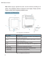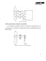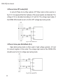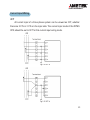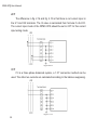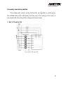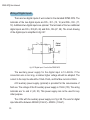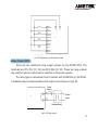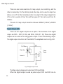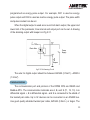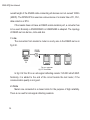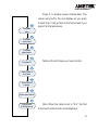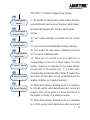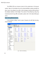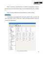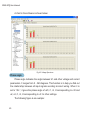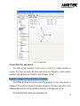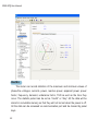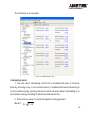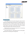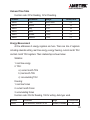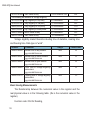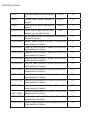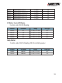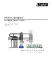
1
DPMS XPQ Multi-Function Power Meter User Manual 1087-332 POWER INSTRUMENTS POWER INSTRUMENTS Copyright 2008© V1.0 This manual may not be reproduced in whole or in part by any means, without the expressed written consent of AMETEK. The information contained in this document is believed to be accurate at the time of publication, however, AMETEK assumes no responsibility for any errors which may appear here and reserves the right to make changes without notice. Please ask your local representative for the latest product specifications before ordering. I DPMS XPQ User Manual Please read this manual carefully before installation, operation and maintenance of the DPMS XPQ meter. The following symbols are used in this user’s manual and on the DPMS XPQ meter to alert the danger or to prompt in the operating or setting process. Danger symbol, Failure to observe the information may result in injury or death. Alert symbol, Alert to potential danger. Observe the information after the symbol to avoid possible injury or death. Installation and maintenance of the DPMS XPQ meter should only be performed by qualified, competent personnel that have appropriate training and experience with high voltage and current devices. AMETEK is not liable for any problems that occur under proper operation. II POWER INSTRUMENTS content Chapter 1 Introduction……………………………………………………………………………6 Purpose..................................………………………………………………………7 Application Area..............................………………………………………………………9 Function......................................………………………..……………………………9 Comparison......................................………………………………………….………10 Chapter 2 Installation……………………………………………………………………………12 Appearance and Dimensions……………………..……………………………………13 Installation Method…………………………………………………….……….….……14 Wiring.......................………………………………………………...……………………17 Chapter 3 Meter Operation and Parameter Setting…………….…………………………36 Display Panel and Key………………………………….………………………………37 Metering Data Reading…………………………………...……………….……………39 Statistics Display……………………...…………………………………………………43 Meter Parameter Setting…………….………………….…....…………………………44 Energy Parameter Setting……………………………….………………………..……51 Voltage Eligibility Parameter Setting…………….……….……………………………53 Chapter 4 Function and Software…………………………….………………………..……56 Basic Analog Measurements……………………………....…………………….………57 Event Alarming…………………………………………………………..………………74 Chapter 5 Communication……………………………………………………..…….…………86 Introducing Modbus Protocol…………………….….….………………..………………87 Format of the communication………………………………….….……………………..90 Data Address Table and Application Details........................…..………………………96 Appendix……………………………………………………..……………………..……………122 Appendix A Technical Data and Specification………………………………………123 Appendix B Ordering Information………………………………………………..……127 III DPMS XPQ User Manual Getting Started! Congratulations! You have received an advanced, versatile, multifunction power meter, also known as a Remote terminal unit (RTU), which will greatly benefit your power system. When you open the package, you will find the following items. 1. DPMS XPQ meter 1 2. 14-Pin terminal 2 3. Installation clips 4 4. User’s operation manual 1 5. Maintenance guarantee card 1 Please read this manual carefully before operating or setting the meter to avoid unnecessary results. You can read only part of this manual depending on how you use the meter. Chapter 1 helps you to understand the fundamental function, specification and application area. Chapter 2 describes detailed installation and wiring. Chapter 3 describes the data display and parameter setting method. Chapter 4 outlines the functions of the meter and the way to use them. Chapter 5 gives the address table. Appendix lists the technical data and specifications and ordering information. IV Chapter 1 Introduction Purpose Application Area Functions DPMS XPQ Series 5 DPMS XPQ User Manual Purpose Powerful Multifunction Power Meter The DPMS XPQ series multifunction power meter is the new generation of the very popular DPMS. It has more functions and higher accuracy. It not only integrates three-phase energy measuring and displaying, energy accumulating, harmonic measuring, malfunction alarm, statistics and records, digital input / output and network communication, but also contains the following functions: four quadrant energy measuring, time-of-use (TOU), auto-freezing, waveform and over range waveform capture, programmable over range alarming, schedule of events, trending records etc. Graceful and high-lighted back light makes it easy to check the measuring data. Simple HMI interface makes it easy to master. The multi-row display lets you observe various data without touching any keys. Ideal Choice for Electric Automation SCADA System The DPMS XPQ can be used to replace all traditional electric meters. It also can be used as a Remote Terminal Unit (RTU) for monitoring and controlling in a SCADA system. All the measured data is available via digital RS485 communication ports running the ModbusTM protocol. Energy Management The DPMS XPQ can measure double direction four quadrant kWh and kVARh with accuracy up to class 0.5S of IEC60253-22. It can provide maximum/ minimum energy data and energy demand data. With the help of software, you can easily know how the load and energy are running. It also gives you all kinds of measurement tables. 6 POWER INSTRUMENTS Remote Power Control The main function of the DPMS XPQ is measurement, but it also has some flexible I/O functions. This makes the meter very useful as a distributed RTU (metering, monitoring, remote controlling in one unit). Power Quality Analysis With the powerful digital signal processing ability, the DPMS XPQ intelligent power meter can be used as an online power quality analysis instrument. It can simultaneously and continuously give out the analysis results such as THD of voltage and current, harmonics up to the 31st order and an unbalance factor of voltage and current, etc. Main functions of the DPMS XPQ are listed in table 1.1. Metering Energy VLN, VLN average, VLL, VLL average. I, I average, IN. Power, Reactive Power, Apparent Power and Power factor of each phase and total. Frequency. Bidirectional, four quadrants and system Energy, Reactive Energy, Apparent Energy Programmable energy freezing. Period Energy, Reactive Energy, Apparent Energy Four time zone schedules. Statistics and Records Energy and Demand Max/Min value of statistics with time stamp Maximum of Demand SOE, Waveform capture and records kWh, kVARh of 4 quadrants: Import, Export, Total, Net Demand of Power and Reactive Power Power Quality Analysis Over range Alarming THD, Even THD and Odd THD of Voltage, Current Harmonics and Crest factor of Voltage Telephone Harmonic waveform Factor (THFF). Harmonics and K Factor. Unbalance Factor of Voltage and Current. Statistics of Voltage Eligibility. Monitor up to 240 parameters. Programmable parameter limitations. Programmable alarming logic. Alarming outputs combined with DO or Relays. Auto-recording of alarming events. Alarming-trigger waveform recording. Communication I/O port and Control RS485 Communication port. Modbus RTU Protocol 4 Digital Input (DI) (Wet or Dry) 2 Relay Output and 2 Digital Output (DO) Table 1.1 Main functions of the DPMS XPQ series 7 DPMS XPQ User Manual Application Area Power Distribution Automation Intelligent Electric Switch Gear Industry Automation Building Automation Energy Management System Large UPS System Function Multifunction, High Accuracy The DPMS XPQ sSeries multifunction Intelligent power meter is powerful in data collecting and processing. Electric power parameters; metering, energy accumulating ,harmonic measuring, malfunction alarming, statistics and records, digital input /output and network communication, four quadrant energy measuring, time-of-use(TOU), auto-freezing, waveform and over range waveform capture, programmable over range alarming, schedule of events, trending records etc. Accuracy of Voltage and Current is 0.2%, True-RMS Accuracy of Power and Energy is 0.5%, four quadrants metering. Small Size and Easy Installation With the size of DIN96 ×96 and 55mm depth after mounting, the DPMS XPQ can be installed in a small cabin. The fixing clips are used for easy installation and removal. Easy to Use With a large high density LCD screen, the display of the DPMS XPQ is easy to read and use. All the setting parameters can be accessed by using panel keys or a communication port. The setting parameters are protected in 8 POWER INSTRUMENTS EEprom, which will maintain its content after the meter is powered off. With the backlight of the LCD, the display can be easily read in a dim environment. The back light “on” time is selectable. Multiple Wiring Modes The DPMS XPQ can easily be used in either: high voltage, low voltage, three phase three wires, three phase four wires or a single phase system. High safety, high stability, the DPMS XPQ was designed according to industrial standards. It can run stably under high power disturbance conditions as it has passed IEC and CE. Comparison To meet different demands of customers, the DPMS XPQ series consists of four types: DPMS XPQ-D (time-of-use pattern), DPMS XPQ-E (power quality pattern), DPMS XPQ-F (waveform and alarming pattern) and DPMS XPQ-G (general function pattern). In order to introduce them all, this manual is based on the DPMS XPQ-G. Other patterns may not contain some functions so please refer to the following table carefully. Table 1.2 Comparison of the DPMS XPQ series Function Basic parameters Digital I/O Demand Basic settings Device property D E F G ● ● ● ● ● ● ● ● ● ● ● ● ● ● ● ● ● ● ● ● 9 DPMS XPQ User Manual Harmonics THD Phases and all phase Voltage harmonic analysis current harmonic analysis Function Sequence phase angle Energy MAX/MIN Voltage eligibility SOE log Alarm log Waveform log Trending log System status Alarm Others 10 D Real time Current month TOU Previous month TOU Accumulative TOU Frozen Real time Current month TOU Accumulative TOU Current Previous Daily, Monthly, Yearly, Frozen, Accumulative ● ● ● ● ● ● ● ● ● ● ● ● ● ● ● ● E F G ● ● ● ● ● ● ● ● ● ● ● ● ● ● ● ● ● ● ● ● ● Alarming record SOE, waveform, trending Schedule of TOU Run time Alarming Waveform triggering Max and Min recording mode Trending settings ● ● ● ● ● ● ● ● ● ● ● ● ● ● ● ● ● ● ● ● ● ● ● ● ● ● ● ● ● ● Chapter 2 Installation Appearance and Dimensions Installation Method Wiring 11 DPMS XPQ User Manual Note: Before trying to operate the meter, note the functions according to its pattern. The installation method is introduced in this chapter. Please read this chapter carefully before beginning installation work. Appearance and Dimensions 6 3 7 2 8 1 5 4 Fig 2.1 Appearance of the DPMS XPQ PART NAME DESCRIPTION 1. Enclosure The DPMS XPQ enclosures are made of high strength anticombustible engineered plastic 2. Front Casing After the installation, this part is before the panel. The color of the front casing is optional 3. LCD Display Large bright blue backlight LCD Display 4. Key Four keys are used to select display and to set parameters of the meter 5. Input Wiring Terminals Used for Voltage and Current input 6. Auxiliary Wiring Terminals Used for auxiliary power, communication and DI 7. Extend Wiring Terminals Auxiliary I/O wiring terminals 8. Installation Clip The clips are used for fixing the meter to the panel Table2.1 Part Names of the DPMS XPQ 12 POWER INSTRUMENTS Dimensions Front 43.00 96.00 96.00 Side 38.50 55.00 96.00 Fig 2.2 Dimensions Installation Method Environmental Before installation, please check the environment temperature and humidity to ensure the DPMS XPQ meter is being placed where optimum performance will occur. Temperature Operation: -25 - 70 deg. Storage: -40 - 85 deg. Humidity 5% - 95% non-condensing 13 DPMS XPQ User Manual The meter should be installed in a dry and dust free environment and avoid heat, radiation and high electrical noise sources. Maximum Altitude: 2,000m Site Requirement: Indoor Use Installation Steps Normally, meters are installed on the panel of switch gear. 1. First, cut a square hole on the panel of the switch gear. The cutting size is in fig 2.3 Unit (mm) 0.5 90± 0.0 Cut panel 0.5 90± 0.0 Fig 2.3 Panel Cutting 2. Second, remove the clips from the meter and insert the meter into the square hole from the front side. 14 Fig 2.4 Put the meter into the square hole POWER INSTRUMENTS 3. Finally, install clips back on the meter from the backside and push the clip tightly so that the meter is affixed on the panel. panel Fig 2.5 Use the clips to affix the meter on the panel c a Space required for Installation The space around the meter should be large enough so that the meter removal, terminal strip wiring and wire arrangement could be done easily. The recommended minimum space around the meter is shown in Table 2.2 and Fig 2.6. d Panel f b e g panel Fig 2.6 Space around the meter 15 DPMS XPQ User Manual Environment Temperature Minimum Distance(mm) a b c d e <50℃ 25 25 38 38 64 ≥50℃ 38 38 51 51 76 f 25 38 g 25 38 Table 2.2 Minimum Space Wiring Terminal Strips There are three terminal strips on the back: Voltage & Current input, Auxiliary and Extend. Only the DPMS XPQ with the PRIO option has the Extend Terminal Strip. The 1, 2 and 3 are used to represent each phase of a three phase system. They have the same meaning with A, B and C or R, S and T in a three phase system. Voltage & Current Input Terminal Strip Auxiliary Terminal Strip Note: NC means No Connection 16 POWER INSTRUMENTS Extend Terminal Strip Fig 2.7 Terminal Strips DANEROUS Only qualified personnel should do the wire connection work. Make sure the power supply is off and all the wires are powerless. Failure to observe this may result in severe injury or death. Safety Earth Connection Before doing the meter wiring connection, please make sure that the switch gear has a safety Earth system. Connect the meter safety earth terminal to the switch gear safety earth system. The following safety earth symbol is used in this user’s manual. Auxiliary Power The auxiliary power supply of the meter is 100Make sure the auxiliary 240Vac (50/60Hz) or 100-300Vdc. The meter’s typical power terminal of the meter, G, is connected power consumption is less than 2W. A regulator or a to the safety Earth of UPS should be used when the power supply undulates switchgear. too much. The terminals for the auxiliary power supply are 20, 22 and 24 (L, N, G). A switch or circuit-breaker should be included in the building installation, and it should be in close proximity to the equipment and within easy reach of the operator, and it should be marked as the disconnecting device for the equipment. Note 17 DPMS XPQ User Manual Note 1A FUSE Make sure the power supply voltage is the same as what the meter needs for its auxiliary power. Power Supply Ground 20 L 22 N Acuvim-X 24 G Fig 2.8 Wiring of Power Supply A fuse (typical 1A/250Vac) should be used in the auxiliary power supply loop. No.24 terminal must be connected to the safety earth system of switchgear. An isolated transformer or EMI filter should be used in the auxiliary power supply loop if there is a power quality problem in the power supply. 1A FUSE Power Supply Ground L L Power filter N 20 L N 22 N Acuvim-X G G 24 G Fig 2.9 Wiring of Aux. Power Supply with power line filter Choice of wire should be AWG22~16 or 0.6~1.3mm2. Note: A filter should be used if there is an EMI problem. Note The secondary of PT can not be shorted, otherwise it may cause the severe damage of the instrument. 18 Voltage Input Meter input voltage should be 40~230Vac L-N, 60~400Vac. L-L. The voltage input could be directly connected to the meter terminal without the use of PT if the voltage system is less than 400Vac (L-L). If the input Voltage is higher than 400Vac, a PT or VT should be POWER INSTRUMENTS used. A fuse (typical 1A/250Vac) should be used in the voltage input loop. A PT should be used to transform the high voltage into the measurement range of the meter if it is used in a high voltage system. The wire gauge of the input voltage should be AWG16~12 or 1.3~2.0mm2. Note: In no circumstances should the PT secondary be shorted. The PT secondary should be well grounded at one end. Current Input In a practical engineering application, CTs should be installed in the measuring loop. Normally the CT secondary is 5A. 1A is possible as an option. A CT accuracy over 0.5% (rating over 3VA) is recommended and it will influence the measuring accuracy. The wire between the CT and meter should be as short as possible. The length of the wire may increase the error of the measurement. CTs must be required for rated current over 5A. The wire guage of the input current should be AWG15~10 or 1.5~2.5mm2. Note: The CT loop should not be open in any circumstances when the power is on. There should not be any fuse or switch in the CT loop and one end of the CT loop should be connected to the ground. Vn Connection Vn is the reference point of meter input voltage. The lower the wire resistance the lower the error. Three phase wiring diagram The DPMS XPQ can satisfy most kinds of three phase wiring diagrams. Please read this part carefully before you begin to do the wiring so that you may chose a wiring diagram suitable for your power system. 19 DPMS XPQ User Manual The voltage and current input wiring mode can be set separately in the meter parameter setting process. The voltage wiring mode could be 3-phase 4-line Wye (3LN), 3-phase 4-line 2PT Wye mode (2LN) and 3-phase 3-line open delta (2LL). The current input wiring mode could be 3CT, 2CT and 1CT. Any voltage mode could be grouped with one of the current modes. Voltage Input Wiring 3-Phase 4-Line Wye mode (3LN) The 3-Phase 4-Line Wye mode is commonly used in low voltage electric distribution power systems. The power line can be connected to the meter voltage input directly as in fig 2.10a. In the high voltage input system, 3PT Wye mode is often used as in fig 2.10b. The voltage input mode of the DPMS XPQ should be set to 3LN for both voltage input wiring modes. Acuvim-X Fig 2.10a 3LN direct connection 20 POWER INSTRUMENTS Fig 2.10b 3LN with 3PT 3-Phase 3-Line direct connection mode (3LN) In a 3-Phase 3-Line system, power line A, B and C are connected to V1, V2 and V3 directly. Vn is floated. The voltage input mode of the DPMS XPQ should be set to 3LN. Acuvim-X Fig 2.11 3LN 3-Phase 3-Line direct connection 21 DPMS XPQ User Manual 3-Phase 4-Line 2PT mode (2LN) In some 3-Phase 4-Line Wye systems, 2PT Wye mode is often used as in fig 2.12. It is supposed that the 3 phases of the power system are balanced. The voltage of V2 is calculated according to V1 and V3. The voltage input mode of the DPMS XPQ should be set to 2LN for 2PT voltage input wiring mode. Fig 2.12 2LN with 2PTs 3-Phase 3-Line open Delta Mode (2LL) Open delta wiring mode is often used in high voltage systems. V2 and Vn connect together in this mode. The voltage input mode of the DPMS XPQ should be set to 2LL for voltage input wiring mode. Fig 2.13 2LL with 2PTs 22 POWER INSTRUMENTS Current Input Wiring 3CT All current input of a three phase system can be viewed as 3CT, whether there are 2 CTs or 3 CTs on the input side. The current input mode of the DPMS XPQ should be set to 3CT for this current input wiring mode. Fig 2.14 3CT-a Fig 2.15 3CT-b 23 DPMS XPQ User Manual 2CT The difference in fig. 2.16 and fig. 2.15 is that there is not current input in the I21 and I22 terminals. The I2 value is calculated from formula i1+i2+i3=0. The current input mode of the DPMS XPQ should be set to 2CT for this current input wiring mode. Fig 2.16 2CT 1CT If it is a three phase balanced system, a 1 CT connection method can be used. The other two currents are calculated according to the balance supposing. Fig 2.17 1CT 24 POWER INSTRUMENTS Frequently used wiring method The voltage and current wiring method are put together in one drawing. The DPMS XPQ meter will display normally only if the setting of the meter is associated with the wiring of the voltage and current input. 1. 3LN, 3CT with 3 CTs Fig 2.18 3LN, 3CT with 3CTs 25 DPMS XPQ User Manual 2. 3LN, 3CT with 2 CTs Fig 2.19 3LN, 3CT with 2 CTs 3. 2LN, 2CT Fig 2.20 2LN, 2CT 26 POWER INSTRUMENTS 4. 2LN, 1CT Acuvim-X Fig 2.21 2LN, 1CT Fig 2.21 2LN, 1CT 5. 2LL, 3CT Fig 2.22 2LN, 3CT 27 DPMS XPQ User Manual 6. 2LL, 2CT Fig 2.23 2LL, 2CT 7. 2LL, 1CT 28 Fig 2.24 2LL, 1CT POWER INSTRUMENTS 8. Single Phase 2 Line (Wiring mode setting 3LN, 3CT) Fig 2.25 Single Phase 2 Lines 9. Single Phase 3 Line (Wiring mode setting 3LN, 3CT) Fig 2.26 Single Phase 3 Line 29 DPMS XPQ User Manual Wiring of Digital Inputs There are two digital inputs of wet contact in the standard DPMS XPQ. The terminals of the two digital inputs are DI1+, DI1- (15, 16) and DI2+, DI2- (17, 18). Additional two digital inputs are optional. The terminals of the two additional digital inputs are DI3+, DI3-(25, 26) and DI4+, DI4-(27, 28). The circuit drawing of the digital input is simplified in fig 2.27. Optical Isolator Acuvim-X fig 2.27 DigitalDigital Input Input CircultCircuit of the DPMS XPQ-X Fig 2.27 of Acuvim The auxiliary power supply for the digital input is 12~24Vdc. If the connection wire is too long, a relative higher voltage should be adopted. The current in the loop line should be 10mA~15mA, and the Max current is 30mA. A DI auxiliary power supply (optional) is provided for the convenience of field use. The voltage of the DI auxiliary power supply is 15Vdc (1W). The wiring terminals are V+ and V- (29, 30). This power supply can not be used for any other purpose. The 4 DIs with the auxiliary power supply is in fig 2.28. The wire for digital input should be between AWG22 (0.5mm2)~ AWG16 (1.3mm2). 30 POWER INSTRUMENTS Acuvim-X Relay Output (RO) Fig 2.28 Digital Input with Auxiliary Power Fig 2.28 Digital Input with Auxiliary Power There are two additional relay output options for the DPMS XPQ. The terminals are R11, R12 (31, 32) and R21, R22 (33, 34). These two relay outputs are used for remote control electric switches in the power system. The relay type is mechanical Form A contact with 3A/250Vac or 3A/30Vdc. A mediate relay is recommended in the output circuit shown in fig 2.29. Power Supply Control output Acuvim-X Mediate Relay Fig 2.29 Fig 2.29 RelayRelay outputoutput 31 DPMS XPQ User Manual There are two mode selections for relay output, one is latching, and the other is momentary. For the latching mode, the relay can be used to output two states, on or off. For the momentary mode, the output of the relay changes from off to on for a period of time Ton and then goes off. Ton can be set from 503000ms. The wire for relay output should be between AWG22 (0.5mm2)~AWG16 (1.3mm2). Digital Output (DO) There are two digital outputs as an option. The terminals of the digital output are DO1+, DO1-(35, 36) and DO2+, DO2-(37, 38). These two digital outputs can be used as an energy pulse output or over limit alarming output. The digital output circuit form is Photo-MOS. The simplified circuit is in fig 2.30. Photo -Mos Power Supply Acuvim-X FigFig 2.302.30 Digital output Circuit Digital output Circuit The Max output voltage and current are 100V and 50mA. When the digital output is used as pulse output, DO1 and DO2 can be 32 POWER INSTRUMENTS programmed as energy pulse output. For example, DO1 is used as energy pulse output and DO2 is used as reactive energy pulse output. The pulse width and pulse constant can be set. When the digital output is used as an over limit alarm output, the upper and lower limit of the parameter, time interval and output port can be set. A drawing of the alarming output with beeper is in fig 2.31. Photo -Mos Power Supply Acuvim -X Beeper fig 2.31 Do Alarming Circult Fig 2.31 DO Alarming Circuit The wire for digital output should be between AWG22 (0.5mm2) ~AWG16 (1.3mm2). Communication The communication port and protocol of the DPMS XPQ are RS485 and Modbus-RTU. The communication terminals are A, B, and S (11, 12, 13). A is differential signal +, B is differential signal - and S is connected to the shield of the twisted pair cable. Up to 32 devices can be connected on an RS485 bus. Use good quality shielded twisted pair cable, AWG22 (0.5mm2) or larger. The 33 DPMS XPQ User Manual overall length of the RS485 cable connecting all devices can not exceed 1200m (4000ft). The DPMS XPQ is used as a slave device of a master like a PC, PLC, data collector or RTU. If the master does not have an RS485 communication port, a converter has to be used. Normally a RS232/RS485 or USB/RS485 is adopted. The topology of RS485 net can be line, circle and star. 1. Line The connection from master to meter is one by one in the RS485 net as in fig 2.32. Converter Master PC Acuvim-X Acuvim-X Acuvim -X Fig 2.32 Line mode fig 2.31 Line Mode In fig 2.32 the Rt is an anti-signal reflecting resistor 120-300 ohm/0.25W. Normally, it is added to the end of the circuit beside the last meter, if the communication quality is not good. 2. Circle Meters are connected in a closed circle for the purpose of high reliability. There is no need for anti-signal reflecting resistors. 34 POWER INSTRUMENTS 232 /485 Converter Master PC Acuvim-X Acuvim-X Acuvim-X Acuvim-X Acuvim-X Acuvim-X fig 2.31 Circle Mode Fig 2.33 Circle mode 3. Star The connection for RS485 net is in Wye mode. An anti-signal reflecting resistor may be needed in each line. 232/485 Converter Master PC Acuvim-X Acuvim-X Acuvim-X Acuvim-X Acuvim-X Acuvim-X Fig 2.34 Star mode fig 2.31 Star Mode 35 DPMS XPQ User Manual Recommendations for high quality communication: Good quality shielded twisted pair of AWG22 (0.6mm2) or larger is very important. The shield of each segment of the RS485 cable must be connected to the ground at one end only. Keep communication cables as far away as possible from sources of electrical noise. Use an RS232/RS485 or USB/RS485 converter with optical isolated output and surge protection. 36 Chapter 3 Meter Operation and Parameter Setting Display Panel and Keys Metering Data Reading Statistics Display Meter Parameter Setting Energy Parameter Setting Voltage Eligibility Parameter Setting 37 DPMS XPQ User Manual Detailed human-machine interface of the meter will be described in this chapter. It includes how to get the metering data and how to do the parameter setting. This chapter is based on the DPMS XPQ-G, but other patterns can be operated the same way. Display Panel and Key There is one display panel and four keys in the front of meter. All the display segments are illustrated in fig 3.1. 1 13 3 4 7 5 6 2 1 2 3 4 5 6 7 8 8 12 9 Fig 3.1 All Display Segments 10 11 fig 3.1 All display segments 38 POWER INSTRUMENTS Table 3.1 Display Panel description SN 1 2 3 4 5 6 7 8 9 10 11 12 13 Display Description Item label letter, MAX, MIN, Demand, PF and F Item label: U: voltage, I: current, P: power, q: reactive power, S: apparent power, PF: power factor, F: frequency, MAX: Maximum value, MIN: Minimum Value, Demand:Demand value, Avg: average value, I with N: neutral current, PF, F, Avg and N indicate the data in the fourth line. Three phase unbalance label Load characteristic With letter U: Voltage unbalance factor With letter I: Current unbalance factor Capacitor label: capacitive load; Inductor: inductive load TOU indicator 1, 2, 3, 4 stands for sharp, peak, normal and valley Four lines of letter in Display metering data: Voltage, Current, Power, Power factor, Frequency, THD, Demand, Unbalance factor, the Max/Min Value etc. metering area One line of letter in Energy data display or real time clock the energy display area Load rate Display load current to rating current percentage Energy label imp: consumption energy; exp: generating energy; total: absolute sum of imp and exp energy; net: algebraic sum Communication indicator No label: no communication; One label: inquiry Two labels: inquiry and answer Energy pulse No label: no pulse output; output indicator With label: pulse output Digital input indicator Switch 1 to 4 indicate DI1 to DI4 Time label Time display in energy area Unit Indicate data unit Voltage: V, kV, Current: A, Power: kW and MW, Reactive Power: kVar and MVar, Apparent Power: kVA and MVA, Frequency: Hz, Energy: kWh, Reactive Power: kVARh, Percentage: % 39 DPMS XPQ User Manual There are four keys on the front panel, labeled as H, P, E and V/A from left to right. Use these four keys to read metering data and set the parameters. Metering Data Reading Normally, it displays the metering data, such as voltage, current, power etc. There are several key patterns: press H, P, E, V/A and press key P and key V/A simultaneously. V/A Three phase Voltage & avg V/A Three phase Current & avg Press V/A to read voltage and current in the metering area. The screen will roll to the next display as you press V/A each time. It will go back to the first screen if you press V/A at the last screen. V/A Line Voltage & avg Table on the left shows you how it scrolls: V/A Current & avg V/A Three phase Current demand 40 Note: When the meter is set to “2LL”, there is no phase voltage and neutral current display. So only the third, fourth and fifth screens will be displayed. POWER INSTRUMENTS P Three phase power Press P, to display power related data. The screen will scroll to the next display as you press P each time. It will go back to the first screen if you press P at the last screen. P Three phase reactive power P Three phase apparent power P Three phase PF Table on the left shows you how it scrolls: P Systerm power & power factor P Systerm power & frequency P Systerm power demand P Systerm power Predicting demand Note: When the meter is set to “2LL”, the first to the fourth screens will not be displayed. 41 DPMS XPQ User Manual H THD of phase or line power H THD of line current H Unbalance factor H Voltage Eligibility Press H, to display power quality data, including THD, unbalance factor and voltage eligibility. The screen will scroll to the next display as you press H each time. It will go back to the first screen if you press H at the last screen. The following table shows you how it scrolls: Note 1: Some patterns do not have these functions so the key function and display are invalid. Note 2: When the meter is set to “2LL”, THD, unbalance factor and voltage eligibility are based on the line-to-line voltage; otherwise they are based on the phase voltage. Press E to display energy and the real time clock. The screen will scroll to the next display as you press E each time. It will go back to the first screen if you press E at the last screen. The unit of power is kWh and kVARh for reactive power. The running time begins to record at the time when the meter is turned on, with the accuracy of 0.01H and is stored in the nonvolatile memory. It can be reset via communication port. The following table shows you how it scrolls: Note: Patterns without TOU functions will not display the 9th~16th screens. 42 POWER INSTRUMENTS E Consumption energy E Meter running time Generation energy E E Total energy Time. Format: hh:mm:ss. E E Net energy E The absorption reactive energy E The generation reactive energy E Total reactive energy E Net reactive energy E Consumption energy of sharp time E Consumption energy of peak time Date.Format: mm:dd:yyyy E Absorption reactive energy of normal time E Absorption reactive energy of valley time E Absorption reactive energy of peak time E Absorption reactive energy of sharp time E Consumption energy of normal time E Consumption energy of valley time E 43 DPMS XPQ User Manual Statistics Display Press the P and V/A keys simultaneously, the Max and Min value of metering data will be displayed on the screen. The time stamp can be accessed through the communication port. P is used to change the display between MAX and MIN, V/A is used to scroll the screen. The screen will scroll to the next display as you press V/A each time. It will go back to the first screen if you press V/A at the last screen. It will exit whenever you press P and V/A Keys simultaneously. The following shows you how it scrolls: P + V/A Max value of phase voltage V/A Max value of the line to line voltage V/A Max value of current V/A Max value of power V/A Max value of current harmonics V/A Max value of voltage harmonics V/A Max value of unbalance factor V/A Max value of current demand V/A Note: Set to "2LL", there is no display of "Max value of phase voltage". 44 POWER INSTRUMENTS Note The secondary of the PT can not be shorted, otherwise it may cause severe damage to the instrument. Meter Parameter Setting Under the metering data display mode, press the H and V/A key simultaneously, to get into the meter parameter setting mode. Most of the settings can be done through the keys on the panel. In the meter parameter setting mode, press H to move the cursor. Right moves one digit each time. Press P for increasing and press E for decreasing. Press V/A for acknowledgment and going to the next setting item page. Press H and V/A page keys simultaneously to exit in any setting item page. An access code is needed to access the parameter setting mode. Only the person who knows the access code can do the parameter setting. The access code is 4 digits decimal. It is from 0000 - 9999. The factory default is 0000. After you key in the right access code, press V/A to go to the first parameter setting page, otherwise go back to the metering data display page. The following table shows you how to set it: 45 DPMS XPQ User Manual P + V/A Access code page V/A 01: Address setting V/A 02: Baud rate setting V/A 03: Voltage input wiring V/A 04: Current input wiring V/A 05: PT primary V/A 06: PT secondary V/A 07: CT primary 01: It is any digit from 1 - 247. 02: 1200, 2400, 4800, 9600, 19200, 38400bps are available. 03: Voltage input could be one of three modes, 3LN, 2LN and 2LL. (Refer to chapter 2) 04: could be one of the three modes, 3CT, 2CT and 1CT. (Refer to chapter 2) 05: PT1 value is an integer from 50.0 - 500000.0, the unit is volt. 06: PT2 value is an integer from 100 - 400. The unit is volt. If there is no PT on the voltage input side of meter, the PT1 and PT2 should be the same and equal to the input rated voltage. 07: CT1 value is an integer from 5 - 50000 for a 5 Amp rated current meter, and 1 - 50000 for a 1 Amp rated current meter. 08: Output mode of DO can be set as alarm (AL) and pulse (PLS). 09: It is an integer from 0 - 4 and stands for no output, consumption energy, generation energy, absorption 46 POWER INSTRUMENTS V/A 08: DO mode setting V/A 09: DO1 output item V/A 10: 09: DO2 output item V/A 11:The DO pulse width V/A 12: Energy pulse rate V/A 13: Relay 1 mode V/A 14: Relay 1 closing time reactive energy and generation of reactive energy respectively. 10: The same as DO1 for setting, and they don’t affect each other. 11: The DO pulse width is an integer from 1 - 50. One digit is 20ms. 12: Pulse rate means the energy value per pulse. It can be an integer of 1 - 6000. One digit is 0.1kWh or 0.1kVarh. 13: For the latching mode, the relay can be used to output two states: on or off. For the momentary mode, the output of the relay changes from off to on for a period of time, Ton and than goes off. Ton can be set from 50-300ms. (0: latching; 1: momentary). 14: When the relay mode is set to momentary, the closing time, Ton is an integer from 50 - 3000ms. 15: The same as Relay1. 16: The same as Relay1 and they don’t affect each other. 17: The “on” time can be set from 0 - 120 minutes. The back light will always be “on” if the setting value is 0. If it is another value, it means after a long time it goes off if no key has been pressed. It will be “on” whenever you 47 DPMS XPQ User Manual V/A 15: Relay 2 mode V/A 16: Relay 2 closing time V/A 17: Display back light “ on” time V/A 18: MAX Statistic time mode V/A 19: Clearance of the Max and Min value V/A 20: Demand calculation mode V/A 21: Demand period V/A 22: Demand subinterval press any key if it is “off”. 18: 0 and 1 stands for current month and current day respectively. 19: To clear the Max and Min value does not mean write 0 to all the registers, it will copy the metering value to the statistic registers and start a new statistic period. 20: 1,2,3,4 stands for sliding window, fixed window, rolling window and thermal respectively. 21: 1 - 60 minutes are available. 22: 1 - 60 minutes are available, but the demand period must be divided exactly by the demand subinterval. 23: To clear demand memory means set “0” to all the registers used in the demand calculation. 24: To clear the peak demand means just set “0” to the peak demand registers and will not affect others. 25: “0” stands for no synchronous triggering, “1” for DI1 as the trigger, “2” for DI2 as the trigger, “3” for DI3 as the trigger and “4” for DI4 as the trigger. 26: “1” stands for from OFF to ON; “2” stands for from 48 POWER INSTRUMENTS ON to OFF; “3” stands for trigger at any change. V/A 23: Clearance of peak demand V/A 24: Clearance of peak demand memory V/A 25: DI synchronization triggering demand V/A 26: DI synchronization triggering mode V/A 27: Current I1 direction V/A 28: Current I2 direction V/A 29: Current I3 direction 27, 28, and 29: To adjust polarity of the current, the three currents direction can be set as “Negative” which means reversing 180 degrees and “Positive” which means normal. 30: “yes” means alarming is available and “no” means not. 31: “yes” means the backlight flashes during alarming. 32: “yes” means the relay works in alarming mode and “no” for remote controlling mode. 33: There are 16 records in all and each one is corresponding to one bit of a 16-bit register. For each record, it works or not depends on the enable setting. If some bits of the register are “1”, it means their corresponding records take effect. While “0” means they don’t work. On the panel, it is set as decimal but in the register it is binary, so it needs conversion. 34: When DO1 works in alarming mode, it is controlled by a 16-bit register which determines which record will output to DO1. On the panel, it is set as decimal but in the register it is binary, so it needs conversion. 35: When DO2 works in alarming mode, it is controlled by a 16-bit register which determines which record will 49 DPMS XPQ User Manual V/A 30: Alarming enable V/A 31: Backlight flashing V/A 32: Relay for alarming V/A 33: Alarming records enable V/A 34: Alarming output to DO1 V/A 35: Alarming output to DO2 V/A 36: Alarming output to RO1 V/A 37: Alarming output to RO2 50 output to DO2. On the panel, it is set as decimal but in the register it is binary, so it needs conversion. 36, 37: The same as DO1 and DO2. 38: Two alarm rules can be logically “and” by controlling the logic switch. When two alarm rules are logical and the alarming works, only both of them are true. This function is controlled by the low 8 bits of a 16-bit register; each bit is corresponding to a group. “1” means this function is turned on and “0” means off. 39: Any change on DI can trigger waveform capturing. It is controlled by a 16-bit register. Bit1, bit0 controls DI1, bit3, bit2 controls DI2, bit4, bit5 controls DI3 and bit7, bit6 controls DI4. “00” stands for no capturing, “01” capture from off to on, “10” from on to off and “11” for any changes. Note: You should convert the hex number to a binary number first. 40: Under the condition of a blank record, setting “yes” can initialize one record of the waveform capture. 41: After every interval, it records the value of frequency, UA (UAB), IA, UB (UBC), IB, UC (UCA), IC. The values are called trending records. The interval can be set from 1min - 60min with a default of 60min. 42: Display format is MM: DD: YYYY. 43: display format is hh:mm:ss. POWER INSTRUMENTS V/A 38: Logical and between alarm rules 44: This is the last screen of the setting page. The access code can be changed on this page. It is important to remember the new access code. V/A 39: DI triggering waveform mode V/A 40: Manual triggering waveform capture V/A 41: Intervals of trending record V/A 42: system date setting V/A 43: system time setting V/A 44: Access code 51 DPMS XPQ User Manual Energy Parameter setting Pressing H and E simultaneously under the metering data display mode will enter the energy settings page. The key operation is the same as in other setting pages. You need to press H and E simultaneously to exit this mode. H + E Access code page V/A 01: TOU energy enable V/A 02: TOU setting reset to default V/A 03: Real time energy reset selection V/A 04: TOU balance mode selection V/A 05: TOU balance time setting V/A 06: Energy freezing mode selection 52 The following table shows you how to set it: 01: TOU can be forbidden in application. 02: TOU time setting is complex, the meter has a default when it leaves the factory. You can use the default or set it yourself. 03: Energy can be reset by writing registers one by one or writing “0” to them all at one time. TOU and real time energy can be reset respectively. 04:“nature” means balance at the end of a month, “assign” means balance at an assigned time every month. TOU balance means to end the accumulation of the energy in the current balance month and begin to accumulate the energy in a new balance month. 05: When “assign” is selected, the time is to be set here, format is dd:hh:mm:ss. 06: Copy the real time energy and TOU energy of current month to the freezing memory. There are two modes. “Assign” means pointing a time to freeze, “at once” means freezing right now. If you select the “assign” mode, you need to set the time on the 8th screen skipping the 7th; if you select the “at once” mode, you need to finish the 7th screen in order to execute the order. POWER INSTRUMENTS V/A 07: Freezing at once setting V/A 07: This screen will display only when you select the “at once”. 08: Freezing time setting 08: Set your time of freezing on this screen when you select the “assign” mode. V/A 09: There are two modes of clearance: “assign” means 09: TOU clearance mode selection clear at an assigned time, this will skip the 10th screen to the 11th to set the time. “At once” means clear at once after you finish the 10th screen. V/A 10: TOU clearing at once setting V/A 11: TOU clearance date setting V/A 12: TOU clearance time setting 13: Energy measuring mode selection V/A 10: Finish this screen when you select the “at once” mode. 11: Execute this order every year at this date:MM:DD. 12: Execute this order every year at this time:hh:mm:ss. 13: “0”stands for fundamental based measuring, “1” stands for all-wave based measuring. 14: “0” stands for mode 0: “1” stands for mode 1: . 14: Apparent power measuring mode 53 DPMS XPQ User Manual Voltage Eligibility Parameter Setting Pressing H and P simultaneously under the metering data display mode will enter the voltage eligibility statistics setting page. The operation of keys is the same as in other setting pages. You need to press H and P simultaneously to exit this mode. Whether the voltage is eligible or not is according to whether the measured voltage is within the limitations set by the user. The limitations of the three phase voltages can be set respectively and the setting value is the same as the communication value, which is the secondary value without PT and CT. The following table shows you how to set it: H + P Access code page V/A 01: High limit of U1(U12) V/A 02: Low limit of U1(U12) 54 01, 02: When the meter is set to “2LL”, it is U12 and U1 for others. POWER INSTRUMENTS V/A 03: High limit of U2 (U23) 03, 04: when the meter is set to “2LL”, it is U23 and U2 for others. V/A 04: Low limit of U2 (U23) V/A 05: High limit of U3 (U31) V/A 06: Low limit of U3 (U31) V/A 07: Voltage Eligibility clearance mode 05, 06: when the meter is set to “2LL”, it is U31 and U3 for others. 07: There are two modes of clearance: “assign” means clear at an assigned time, this will skip the 8th screen to the 9th to set the time. “At once” means clear at once after you finish the 8th screen. After the clearance, all time values will be 0 and voltage eligibility will be 100%. V/A 08: Voltage Eligibility clear at once setting 08: Finish this page when you select the “at once” mode. 55 DPMS XPQ User Manual V/A 09: Voltage Eligibility clearing date setting V/A 10: Voltage Eligibility clearing time setting V/A 11: Voltage Eligibility freezing mode setting V/A 12: Freezing at once setting V/A 13: Freezing date setting V/A 14: Freezing time setting 56 09, 10: Set the time for the “assign” mode. 11: It only freezes real time measurement. There are two modes. “Assign” means pointing a time to freeze, “at once” means freezing right now. If you select the “assign” mode, you need to set the time on the 13th screen skipping the 12th; If you select the “at once’ mode, you need to finish the 12th screen in order to execute the order. 12: if you select the “At once” mode at the “Voltage Eligibility freezing mode setting”, you can go into this page to execute the order at once. 13, 14: The meter will freeze the data at this moment according to its inner clock. Chapter 4 Function and Software Functionality and Utility Software 57 DPMS XPQ User Manual The DPMS XPQ can measure almost all the parameters in the power system. Some of its functions may not be demonstrated by simply pressing the keys, hence, the software to go with it. We’ll introduce functions with the help of the software interface in this chapter. The version of the software you buy may be advanced and it may differ somewhere, please refer to the manual that goes with it. Basic Analog Measurements It can measure voltage, current, power, frequency etc with high accuracy, shown as below: Fig 4.1 Real-Time Metering 58 POWER INSTRUMENTS Note1: It should be clear that there is a defined correspondence between the real value and communication value. For more detail, please refer to chapter 5. Note 2: Settings related to measurements are in system settings. Harmonics It can measure and analyze THD, Harmonics (2nd to 31st), even HD, odd HD, Crest Factor, THFF, K factor etc. Values excluding harmonic ratios are shown in the figure below: Fig 4.2 Total Harmonic Distortion 59 DPMS XPQ User Manual A chart in the software is shown below: Phase angle Fig 4.3 Voltage Spectrum Phase angle indicates the angle between U1 and other voltage and current parameters. It ranges from 0 - 360 degrees. This function is to help you find out the relationship between all input signals avoiding incorrect wiring. When it is set to “2LL”, it gives the phase angle of u23, i1, i2, i3 corresponding to u12 and u2, u3, i1, i2, i3 corresponding to u1 for other settings. The following figure is an example: 60 POWER INSTRUMENTS Fig 4.4 Phase Angles Current direction adjustment The right current direction is from port 1 to port 2. To adjust polarity of current, the three currents direction can be set as “Negative” which means reversing 180 degrees and “Positive” which means normal. Sequence component and unbalance analysis The DPMS XPQ will do some sequential analysis for the input signal. it makes out the positive sequence, negative sequence and zero sequence of the fundamentals and will do the unbalance analysis of voltage and current. The following figure shows a sequence chart: 61 DPMS XPQ User Manual Max/Min Fig 4.5 Sequence Component The meter can record statistics of the maximum and minimum values of phase/line voltages, currents, power, reactive power, apparent power, power factor, frequency, demand, unbalance factor, THD as well as the time they occur. The statistic period can be set as “month” or “day”. All the data will be stored in nonvolatile memory so that they will not be lost when the power is off. All the data can be accessed via communication port and be cleared by panel keys. 62 POWER INSTRUMENTS The following figure is an example: Demand Fig 4.6 Max and Min Types of demands calculated are: consumption power demand of phases A, B, and C, generation power demand of phases A, B, and C, absorption reactive power demand of phases A, B, and C, generation reactive power demand of phases A, B, and C, consumption power demand of three phase, generation power demand of three phase, absorption reactive power demand of three phase, generation reactive power demand of three phase, apparent 63 DPMS XPQ User Manual power demand, current demand of I1, current demand of I2, current demand of I3, current demand of average current, consumption power predictive demand, generation power predictive demand, absorption reactive power predictive demand, generation reactive power predictive demand, and apparent power predictive demand. The values calculated include last period values, current period values, peak demands and their occurring time. Current period values are the calculation values of demand in the current period, while last period values refer to the values achieved for the last completed period. Peak demands are the maximum demands since cleared last time. Time stamp will be stored when the update of the calculation occurs. Peak demand and demand memory can be cleared. To clear is to reset all the registers to 0, like the initial state of the meter (demand calculation only). Demand calculating mode can be set as a sliding window, fixed window, rolling window or thermal demand according to the user. In the sliding window interval, you select an interval from 1 - 60 minutes, which is the period of the calculation. The demand updates every minute. In fixed window interval, select the period of the calculation as mentioned above. The meter calculates and updates the demand at the end of each period. In rolling window interval, you select an interval and a subinterval. The subinterval should divide exactly by the interval. Demands update at the end of each subinterval. Thermal demand method calculates the demand based on a thermal response which mimics the thermal demand meter. You select the period for the 64 POWER INSTRUMENTS calculation and the demands update at the end of each period. Synchronization demand When it is set as a fixed window, rolling window or thermal demand, the period can be synchronized via communication port or by changes of DI. DI Synchronization demand Changes to DI can trigger the synchronization of the demand period. The set is as follows. 1. Select a method from fixed window, rolling window or thermal demand. 2. Select a DI port (address is 1040H) as the trigger, the values are 0~4 corresponding to none and D1~D4. 3. Select the trigger mode of DI (address is 1041H), the values are 1~3 corresponding to from OFF to ON, from ON to OFF, triggering at any change. Command Synchronization demand Using a broadcast command to synchronize the demand, calculation can be set as follows: 1. Select a method from fixed window, rolling window or thermal demand. 2. Broadcast command: the addresses of all the meters are considered 0. Write ff00H to address 8000H using the 10H command. But the receiver may not answer. Note: All operations can only be finished via communication. Using key functions can only partially finish them. 65 DPMS XPQ User Manual Here is an example: Fig 4.7 Demand Here is to set demand: 66 POWER INSTRUMENTS Fig 4.8 Demand Setting Energy Various kinds of energy will be accumulated. The settings are explained in other chapters, so please refer to chapter 3 and chapter 5 carefully. Real time energy: the accumulation of energy for the kWh, kVARh and kVAh since cleared last time. 67 DPMS XPQ User Manual Fig 4.9 Real-Time Energy TOU You can point some different time block to go with different rates (sharp, peak, valley and normal). The meter will calculate the fee according to its inner clock and the settings. So it charges different fees for different rates. 68 POWER INSTRUMENTS The following is an example: Fig 4.10 Current Month TOU Calculating mode 1. You can select calculating mode from a fundamental base or all-wave base by pressing a key or via communication. Fundamental based calculating is to accumulate energy ignoring harmonics while all-wave based calculating is to accumulate energy including fundamental and harmonics. 2. There are two ways to calculate apparent energy(power): Mode 0: S = P 2 + Q2 69 DPMS XPQ User Manual Mode 1: S = P 2 + Q 2 + D2 The following figure shows how to set it: Fig 4.11 Energy Setting Freezing This is to backup the accumulated TOU, current TOU, and real time energy at some time point without affecting the existing data. You can use the freeze data for the statistic applications, with all the values recorded at the same time, enhance the accuracy and efficiency. Freezing can be set automatically or manually making the application very flexible. Here is an example: 70 POWER INSTRUMENTS Fig 4.12 Cumulative TOU TOU calendar: There are four schedules and each schedule has 8 time intervals. Each interval can charge one of the four rates: sharp, peak, valley and normal. Time format for each schedule is: enable | start time mm:dd:hh:mm:ss | end time mm:dd:hh:mm:ss Time format for each interval is: enable | start time hh:mm:ss | end time hh: mm:ss | rate kind 71 DPMS XPQ User Manual You can adjust the calendar to satisfy different uses. To ensure the validity of the calendar setting, the meter will check its rationality strictly. If there is no mistake in the calendar and the TOU function is enabled, TOU accumulation will begin. Requirement of the time format: 1. Schedules must be selected in turn. For example, if you use two schedules, you should enable the first and then the second. 2. The sum of all schedules must be one year. For example, if you only use schedules, the first is from January 1st 03:03:03 to July 6th 02:02:02, the second period must be from July 6th 02:02:02 to January 1st 03:03:03. 3. Start time of the next schedule must be the end time of the last schedule. 4. Schedules in use must be at least 1 and at most 4. 5. The record in use must be at least 1 and most 8 used in turn. If you use 3 intervals, you should use the 1st, 2nd and 3rd. 6. The sum of all time intervals in a schedule must be one day. For example, 3 intervals are enabled, if the first interval is from 03:03:03 to 12:02:02, the second interval is from 12:02:02 to 02:03:03, then the third interval must be from 02:03:03 to 03:03:03. 7. The next start time equals the last end time. 8. Many intervals can share the same rate. Note: You can order special factory settings, the product has default settings. You can reset the meter to default via communication or by key functions. Here is an example: 72 POWER INSTRUMENTS Fig 4.13 TOU Schedules Setting Pulse Energy Output The two digital outputs can be used as energy pulse output and cannot be used as the alarming outputs at the same time. The output energy can be selected among all kinds of energy and reactive energy. Pulse constant and pulse width can be set to meet your requirements. Pulse constant is the kWh a pulse stands for, pulse width is the pulse duration. When the accumulated energy reaches the pulse constant, there will be a pulse on DO. Related parameters: pulse energy output ranges from 0 to 4 corresponding to none, Ep_imp, Ep_exp, Eq_imp, Eq_exp. Pulse constant ranges from 1 - 6000 (integer) with a unit of 0.1kWh (kVARh), apparently that is the resolving power of energy output. 73 DPMS XPQ User Manual Pulse width ranges from 1 - 50 (integer) with a unit of 20ms. The narrowest interval between two pulses is 20ms. In practice the pulse width and the pulse ratio are selected according to system power. The relation of the two parameters should be satisfied by the following expression, In the expression, the Pmax is the maximum power or reactive power. The unit is kW or kVAR. Recommend pulse ratio is 3 to 5 times the right side value Pulse radio > of the above expression. ( pulse width + 1 ) × Pmax 18000000 The related settings are: Fig 4.14 Digital I/O Setting 74 POWER INSTRUMENTS Event alarming When the metering data is over the pre-setting limit and over pre-setting time interval, the over limit alarming will be picked up. The over limit value and time will be recorded and the maximum number of records is 16. The digital output (DO) and RO1, RO2 can be used as a trigger to light or sound alarming. Alarming can also trigger waveform capturing. Application and settings of event alarming: In order to use the event alarming function, you should finish all the settings (equation or in equation or enable switches) correctly, or it will fail. All the settings are to write their corresponding registers via communication. 1. Alarming setting Table 4-1 indicates a group of settings, there are 16 groups in all with the same format. Parameter is the main body. There are 247 parameters in all as shown in table 4-2. We use the serial number instead of its parameter to finish the settings, the serial number will be stored in the first storage unit of every group. What is most important is parameter, so we can calculate some equations or in equations to get the goal. For example, if we want one event of frequency equaling to 50 Hz, we set: serial number: 0; comparison mode: 2; setting value: 5000. Special attention: “setting value” corresponds to main parameter, the relationship between its value and real physical value is the same as the main parameter. 75 DPMS XPQ User Manual “Delay time” indicates the time period that the event keeps happening after the setting equation or in equation is satisfied, which is used to confirm the event. Its value ranges from 0 - 6000 (integer) with a unit of 10ms. There is no delay when it is set to be 0, so the event triggers alarming at once. For example, if it is set to be 20, delay is 20*10=200ms. “Waveform triggering” refers to whether waveform capture works when the set event occurs. address 14F0H 14F1H 14F2H 14F3H 14F4H parameter First group: serial number First group: comparison mode First group: setting value First group: delay time First group: waveform capture range 0~246 1:more,2:equal,3:less Related with parameters 0~6000(*10ms) 1:capture; 0:not capture Table 4-1 first group of alarming settings Serial number parameter 0~32 33 basic analog measurements parameters from“Frequency” to “Loadcharacteristic” discussed in chapter 5. 33~241 209 parameters from “THD_V1” to “K Factor of I3” discussed in chapter 5. 242 Consumption energy predict demand 243 Generation energy predict demand 244 Consumption reactive energy predict demand 245 Generation reactive energy predict demand 246 Apparent energy predict demand Table 4-2 parameters for alarming Thus far, the equations or in equations are finished, but the setting are not finished yet, we have to go through the following steps to finish them. 76 POWER INSTRUMENTS 2. Global settings The addresses of all global variables are 101dH~1024H and 103dH in system parameters discussed in chapter 5. “Alarming enable” determines whether the alarming function of this meter works. Only when it is set as “1”, the alarming function enables. When “Alarming flash enable“ is set to “1”, the backlight will flash when an alarm happens. “Alarming records enable setting” determines whether it records. There are 16 records in all and each one corresponds to one bit of a 16-bit register. For each record, it works or not depending on the enable setting. If some bits of the register are “1”, it means their corresponding records take effect. “Relay for alarming setting”: There are two relays. They can be used as remote controlling output and alarming output. But one can’t work in two modes at the same time. “1” means the relay works in alarming mode and “0” for remote controlling mode. This setting is valid for both relays. “Alarming output to RO1 setting”: when “Relay for alarming setting” is set to be “1”, the relay is available for alarming, but which record it will be driven by and whether output to RO1 or RO2 will depend on other settings. This setting will give an answer. There are 16 records in all and each one corresponds to one bit of a 16-bit register, when the corresponding bit is set to “1”, the relay will close if the alarming condition is satisfied. It opens only when all the alarms related to RO1 recover. If the corresponding bit is set to “0”, RO1 will not be disturbed. Note: When the relay is used in alarming mode, it works in latching mode. There is no pulse mode. So all setting of the relay's working mode will be ignored. 77 DPMS XPQ User Manual “Alarming output to RO2” decides which alarm will be output to RO2. It is set the same as RO1. “Alarming output to DO1 setting”: When “Digital output mode” is set to “1”, DO1 can be used as an alarming output. Which alarm will be output to RO2 is set here. You need to do the same as what you do in setting RO1. “Alarming output to DO2 setting”: The same as “Alarming output to DO1 setting”. “Logical and between alarming setting”: The 16 alarming records are divided into 8 groups. Each group has two records. The two alarms can be logically “and” by controlling the logic switch. When two alarms are logically “and”, the alarming works only when both are satisfied. If the switch is off, the two alarms work independently. The 8 groups are arranged as follows: according to their serial number, the 1st & 2nd make the 1st group as group A; the 3rd & 4th make the 2nd group as group B; The 5th & 6th make the 3rd group as group C; 7th & 8th make the 4th group as group D; 9rd &10th make the 5th group as group E; 11th & 12th make the 6th group as group F; 13th & 14th make the 7th group as group G; 15th & 16th make the 8th group as group H. This function is controlled by the low 8 bits of a 16 bits register, each bit corresponds to a group. “1” means this function is turned on and “0” means off. After finishing the previous settings, the alarming function is turned on. We’ll show you an example of how to use the logical “and” in a group. We set an event as follow: I1 greater than 180A, delay 5s for the 1st record; U1 less than 9980V, delay 10s for the 2nd record. No waveform triggering, 78 POWER INSTRUMENTS no output. The CT primary value of I1 is 200A. The primary voltage of U1 is 10000V, PT2 is 100V. Then let’s look how all the related registers are set. The first record: According to the table, the serial number of I1 is 9 ((14d8H)= 9); Conditions in equation 1 determine the high limit. So “comparison mode” (14d9H) = 1(>). CT1 is 200A, according to the relationship between the communication value and numerical value. I=Rx X(CT1/5)/1000, so I1 is 180A. Then the limit is (14daH) = 4500; Delay 5s, as the unit of Limit_t register is 10ms, so the delay time is (14dbH) = 500; Alarming but no waveform triggering, “waveform capture” (14dcH) = 0. The second record: According to the table, the serial number of U1 is 1 ((14ddH) = 1); Conditions in equation 1 determine the low limit. So “comparison mode” (14d9H) = 3(<); PT1 is 10000V, according to the relationship between the communication value and numerical value, U=Rx X (PT1 / PT2) /10, so the register value should be 998; Delay 10s, as the unit of Limit_t register is 10ms, so the delay time is (14e0H) = 1000; Alarming but no waveform triggering, so “waveform capture” (14e1H) = 0. Settings between the two records: “Alarming output” of the 1st, 2nd(101fH) = 0x0003; No hardware output, (1020H)=0; (1021H)=0;(1022H)=0; (1023H)=0; logical and(1024H)=0x0001; At last, the” alarming enable”, (101dH) =1. Here is a figture showing the alarming settings: 79 DPMS XPQ User Manual Fig 4.15 Alarm Setting Event alarming setting There are 16 of records to be stored. But they are not corresponding to setting records, they record in cycle. The latest event will cover the oldest one. It begins from the 1st record when the power is turned on. When over range parameters resume to normal, the time and value will be recorded as an event as well. So you can work out the continuous time of over range by checking the changing time. Here is the 1st record. Other records have the same format. 80 POWER INSTRUMENTS address 1540H 1541H 1542H 1543H~1549H parameter First group: alarming status First group: parameter number First group: over range or reset value First group: occur time: yyyy mm:dd:hh: mm:ss:ms range 0~65536 0~246 Related with parameters time Table 4-3 alarming status of the 1st record “alarming status” indicates information of the current status. It is a 16-bit unsigned integer. Serial number is stored in the high 8 bits. Bit1 indicates logical and. Bit1=1,yes; Bit1=0,no. Bit0 indicates alarming is to setup or to recover. Bit0=1, setup; Bit0=0, recover. Undefined bits are 0. “Serial number” indicates which parameter is recorded. “Value” indicates alarming limit value. “Time” indicates the time with accuracy of ms. Alarming event will set bit2 of “system status” to 1. At the same time, corresponding flags will be set to 1 to indicate new data. It should be cleared after the controller has read the data, then bit2 of the system parameter will be set to 0. Note: alarming records will not be lost during power off. The pointer will point to the 1st record after it is powered on again. Here is an example: 81 DPMS XPQ User Manual Fig 4.16 Alarm Log SOE Function There are 4 DI inputs, it can record changing information of DIs. The time resolution is 1ms. It can also determine whether to enable waveform capture and which kind of triggering by setting “DI triggering waveform capture mode” in system parameters. Its register forms a 16-bit unsigned integer. Bit1,bit0=DI1; Bit3,bit2=DI2;Bit5,bit4=DI3; Bit7,bit6=DI4. “00” stands for none, “01” stands for from OFF to ON, “10” stands for from ON to OFF ,“11” stands for trigger at any change. Format: DI status | occur time yyyy |mm | dd | hh | mm | ss | ms There are 20 groups of records, it will begin with the first one after power 82 POWER INSTRUMENTS on and it works in a cycle. The data won’t lose during power off SOE will set bit0 of “system status” to be 1. At the same time, corresponding flags will be set to 1 to indicate new data. The meter sets flag of SOE but does not clear it. It should be cleared after controller has read the data, then bit0 of system parameters will be set to 0. Here is an example: Fig 4.17 SOE Log 83 DPMS XPQ User Manual Waveform record The DPMS XPQ can record 5 cycles of waveforms both before and after the trigger point of the entire 6 input channels (U1, U2, U3, I1, I2 and I3). There are 16 points for each cycle and a maximum of 5 waveform records. There are three reasons for waveform triggering: DI changes, alarming and manual triggering. Please refer to related chapters for more details. Format: w1~w7 recording time (w1:yyyy; w2:mm; w3:dd; w4:hh; w5:mm; w6:ss; w7:ms). w8-w10 indicates the trigger: (w8: DI triggering, Bit1,bit0 indicates DI1; Bit3,bit2 indicates DI2; Bit5,bit4 indicates DI3 and Bit7,bit6 indicates DI4. “00” indicates not trigger by DI, “01” indicates trigger by DI from off to on, “10” indicates trigger by DI from on to off and “11” indicates a trigger by DI for any changes. w9: alarming trigger, bit0~bit15 are corresponding to the 1st - 16th of the 16 alarming groups. 1: alarming trigger capture; 0: alarming does not trigger capture. w10: manual triggering.1:yes; 0:no.) Then there are 10 cycle waveform of UA, 10 cycle waveform of IA, 10 cycle waveform of UB, 10 cycle waveform of IB, 10 cycle waveform of UC, 10 cycle waveform of IC. Please refer to the address table for more details. The waveform record will set bit1 of “system status” to 1. At the same time, corresponding flags will be set to 1 to indicate new data. The meter sets the flag of the waveform record but does not clear it. It should be cleared after the controller has read the data, then bit0 of system parameters will be set to 0. Update rule: It checks out empty records from the first one, if there is no blank record, it won’t take a new record. All records won’t be lost during power off. 84 POWER INSTRUMENTS Here is an example: Fig 4.18 Waveform Log Trending records The DPMS XPQ-G takes records of frequency, UA (or UAB), IA, UB (or UBC), IB, UC(or UCA), IC at a fixed interval. So the controller can draw trending charts easily. The time interval can be 1~60 minutes, with the default of 60. It can take 336 records in all and recurs after it is full. It takes the occurring time of the latest record and there are no time stamps for other records. “Trending record pointer” indicates the serial number of the next record. This pointer can 85 DPMS XPQ User Manual not be changed. “Trending record backup pointer” is used by the controller, it stores the serial number that the controller will read, it can not be changed by the meter either. It is used to compare “trending record pointer” with input data from the controller, when the two are equal, bit4 of “system status” will be cleared ensuring all data has been read by the controller. Bit4 of “system status” will be set to 1 when there is a new record. Trending records will not be lost during power off. “Trending record pointer”, “trending record backup pointer” and Bit4 of “system status” will be set to 0 after power on. Here is an example: Fig 4.19 Trending Log 86 POWER INSTRUMENTS Voltage Eligibility The DPMS XPQ-G can take the statistics of voltage eligibility, then give out a great amount of data. Eligibility = (1-overlimit time/Measuring time)*100% The upper and lower limits of voltage can be set according to the user. When voltage is out of range, it is not eligible. Three limitations of voltages of the phase or line can be set respectively. The format of the setting value and communication value is the same. They are all set according to input voltages. For example, if the PT used is a 10000/100 PT, the high limit of voltage is set as 10300V, then the setting value is 10300÷(10000/100)=103V. Then according to the relationship between the communication value and numerical value , U=Rx X (PT1 / PT2) /10, so the value to be written, Rx is 103*10=1030. Setting by pressing keys should use the same value. Voltage eligibility consists of running time, channel eligibility and eligible time. In order to find and analyze, it is divided into real time, statistics, and freezing zone. Please refer to the address table for more details. The format of eligibility is 99.9999999%. Voltage eligibility can be frozen and cleared. Here is an example: 87 DPMS XPQ User Manual Fig 4.20 Voltage Eligibility Ratio 88 Chapter 5 Communication Introducing Modbus Protocol Format of Communication Data Address Table Application Details 89 DPMS XPQ User Manual This chapter mainly discusses how to handle the meter via the communication port using software. To master this chapter, you should be familiar with Modbus and have read the other chapters in this manual. Once you have completed these steps you will have mastered the function and application of this product. This chapter includes: Modbus protocol, the format of communication and data address tables and application details. Introducing Modbus Protocol The Modbus RTU protocol is used for communication in the DPMS XPQ. The data format and error check methods are defined in the Modbus protocol. The half duplex query and respond mode is adopted in the Modbus protocol. There is only one master device in the communication net. The others are slave devices, waiting for the query of the master. Transmission mode The mode of transmission defines the data structure within a frame and the rules used to transmit data. The mode is defined in the following which is compatible with Modbus RTU Mode*. Coding System Start bit Data bits Parity Stop bit Error checking 8-bit binary 1 8 no parity 1 CRC check * Modbus is trademark of Modicon, Inc. 90 POWER INSTRUMENTS Framing Address 8-Bits Function 8-Bits Data N×8-Bits Check 16-Bits Table5.1 Data Frame Format Address Field The address field of a message frame contains eight bits. Valid slave device addresses are 0~247 decimal. A master addresses a slave by placing the slave address in the address field of the message. When the slave sends its response, it places its own address in this address field of the response to let the master know which slave is responding. Function Field The function code field of a message frame contains eight bits. Valid codes are 1~255 decimal. When a message is sent from a master to a slave device the function code field tells the slave what kind of action to perform. Code 01 02 03 05 16 Meaning Read Relay Output Status Read Digital Input(DI) Status Read Data Obtain current Control Relay Output Press Multiple-Register Action Obtain current status of Relay Output Obtain current status of Digital Input binary value in one or more registers Force Relay to a state of on or off Place specific binary values into a series of consecutive Multiple-Registers Table5.2 Function Code Data Field The data field is constructed using sets of two hexadecimal digits, from 00 to FF hexadecimal. The data field of messages sent from a master to slave devices contains additional information which the slave must use to take the action defined by the function code. This can include items like discrete and 91 DPMS XPQ User Manual register addresses, the quantity of items to be handled, and the count of actual data bytes in the field. For example, if the master requests a slave to read a group of holding registers (function code 03), the data field specifies the starting register and how many registers are to be read. If the master writes to a group of registers in the slave (function code 10 hexadecimal), the data field specifies the starting register, how many registers to write, the count of data bytes to follow in the data field, and the data to be written into the registers. If no error occurs, the data field of a response from a slave to a master contains the data requested. If an error occurs, the field contains an exception code that the master application can use to determine the next action to be taken. The data field can be nonexistent (of zero length) in certain kinds of messages. Error Check Field Messages include an error checking field that is based on a Cyclical Redundancy Check (CRC) method. The CRC field checks the contents of the entire message. It is applied regardless of any parity check method used for the individual characters of the message. The CRC field is two bytes, containing a 16 bit binary value. The CRC value is calculated by the transmitting device, which appends the CRC to the message. The receiving device recalculates a CRC during receipt of the message, and compares the calculated value to the actual value it received in the CRC field. If the two values are not equal, an error will result. The CRC is started by 66 first preloading a 16-bit register to all 1’s. Then a process begins of applying successive 8-bit bytes of the message to the current contents of the register. Only the eight bits of data in each character are used for generating 92 POWER INSTRUMENTS the CRC. Start and stop bits, and the parity bit, do not apply to the CRC. During generation of the CRC, each 8-bit character is exclusive ORed with the register contents. Then the result is shifted in the direction of the least significant bit (LSB), with a zero filled into the most significant bit (MSB) position. The LSB is extracted and examined. If the LSB was a 1, the register is then exclusive ORed with a preset, fixed value. If the LSB was a 0, no exclusive OR takes place. This process is repeated until eight shifts have been performed. After the last (eighth) shift, the next 8-bit byte is exclusive ORed with the register current value, and the process repeats for eight more shifts as described above. The final contents of the register, after all the bytes of the message have been applied, is the CRC value. When the CRC is appended to the message, the low-order byte is appended first, followed by the high-order byte. Format of communication Explanation of frame Addr Fun 06H 03H Data start Data start Data #of Data #of CRC 16 CRC 16 reg hi reg lo regs hi regs lo Hi Lo 00H 00H 00H 21H 84H 65H Table 5.3 Explanation of frame In table 5.3, the meaning of each abbreviated word is, Addr: address of slave device Fun: function code Data start reg hi: start register address high byte Data start reg lo: start register address low byte Data #of reg hi: number of register high byte Data #of reg lo: number of register low byte 93 DPMS XPQ User Manual CRC16 Hi: CRC high byte CRC16 Lo: CRC low byte 1. Read Status of Relay (Function Code 01) This function code is used to read status. 1=On, 0=Off; There are 2 Relays. The Address of each Relay is Relay1=0000H and Relay2=0001H. The following query is to read Relay Status of meter number 17. Query Addr Fun 11H relay start relay start relay #of reg hi reg lo regs hi 01H 00H 00H 00H relay #of regs lo 02H CRC 16 CRC 16 Hi Lo BFH 5BH Table 5.4 Read the status of Relay1 and Relay2 Query Message Response The DPMS XPQ response includes the meter's address, function code, quantity of data byte, the data, and error checking. An example response to read the status of Relay1 and Relay2 is shown in Table 4.5. The status of Relay1 and Relay2 is responding to the last 2 bits of the data. Relay1: bit0; Relay2: bit1 Address 11H Function code Byte count 01H 01H Data 02H CRC high D4H CRC low 89H Table 5.5 Relay status responds The content of the data is: 7 0 MSB 94 6 0 5 0 4 0 3 0 2 0 Relay1 = OFF (LSB ), Relay2=ON (Left to LSB ) 1 1 0 0 LSB POWER INSTRUMENTS 2. Read the Status of DI (Function Code 02) 1=On, 0=Off. There are 4 DIs. The Address of each DI is DI1=0000H, DI2=0001H, DI3=0002H and DI4=0003H. The following query is to read the 4 DI Status of Number 17 DPMS XPQ. Query Addr Fun 11H 02H DI start addr hi 00H DI start addr lo 00H DI num hi 00H DI num lo 04H CRC 16 Hi 7BH CRC 16 Lo 59H Table 5.6 Read 4 DIs Query Message Response The meter response includes its address, function code, quantity of data characters, the data characters, and error checking. An example response to read the status of 4 DIs is shown as Table 5.7. The status of each is responding to the last 4 bit of the data. DI1: bit0 DI2: bit1 DI3: bit2 DI4: bit3 Address Function code 11H 02H Byte count 01H Data 03H CRC high E5H CRC low 49H Table 5.7 Read Status of DI The content of the data is, 7 0 MSB 6 0 5 0 4 0 3 0 2 0 DI1=On, DI2=On, DI3=Off, DI4=Off 1 1 0 1 LSB 95 DPMS XPQ User Manual 3. Read Data (Function Code 03) Query This function allows the master to obtain the measurement results of the meter.Table 5.8 is an example to read the 3 measured data (F, V1 and V2) from slave device number 17, the data address of F is 0130H, V1 is 0131H and V2 is 0132H. Addr Fun 11H 03H Response Data start Data start Data #of regs hi addr lo addr hi 01H 30H 00H Data #of regs lo 03H CRC 16 regs Hi 06H CRC 16 regs Lo A8H Table 5.8 Read F, V1, V2 Query Message The meter's response includes its address, function code, quantity of data byte, data, and error checking. An example response to read F, V1 and V2 (F=1388H (50.00Hz), V1=03E7H (99.9V), V2=03E9H (100.1V) is shown in Table 4.9. Addr Fun Byte Data1 Data1 Data2 Data2 Data3 Data3 CRC16 CRC16 count hi Lo hi Lo hi Lo hi lo 11H 03H 06H 13H 88H 03H E7H 03H E9H 7FH 04H Table 5.9 Read F, V1 and V2 Message 4. Control Relay (Function Code 05) Query This message forces a single Relay either on or off. Any Relay that exists within the meter can be forced to be either status (on or off). The address of Relays starts at 0000H (Relay1=0000H, Relay2=0001H). The data value FF00H will set the relay on and the value 0000H will turn it off; all other values are illegal and will not affect that relay. 96 POWER INSTRUMENTS The example below is a request to meter number 17 to turn on Relay1. Addr Fun 11H 05H DO addr hi 00H DO addr lo 00H Value hi FFH Value lo 00H CRC 16 Hi 8EH CRC 16 Lo AAH Table5.10 Control Relay Query Message Response The normal response to the command request is to retransmit the message as received after the relay status has been altered. Addr Fun 11H 05H Relay addr Relay addr Value hi lo hi 00H 00H FFH Value lo 00H CRC Hi 8EH CRC Lo AAH Table5.11 Control Relay Response Message 5. Preset / Reset Multi-Register (Function Code 16) Query Function 16 allows the user to modify the contents of a Multi-Register. Any Register that exists within the meter can have its contents changed by this message. The example below is a request to number 17 to Preset Ep_ imp=(17807783.3KWH), while its Hex Value 0A9D4089H. Ep_imp data address is 0156H and 0157H. Addr Fun Data start Data start Data Data Byte Value Value Value Value CRC CRC register hi register lo register hi register lo count high lo hi lo hi lo 11H 10H 01H 56H 00H 02H 04H 0AH 9DH 40H 89H 4DH B9H Table5.12 Preset KWH Query Message 97 DPMS XPQ User Manual Response The normal response to a preset Multi-Register request includes the meter's address, function code, data start register, the number of registers, and error checking. Addr fun 11H 10H Data start Data start addr lo addr hi 01H 56H Data Data register hi register lo 00H 02H CRC high CRC low A2H B4H Table5.13 Preset Multi-Registers Response Message Data Address Table and Application Details There are several rules to follow in using the meter: 1. Data type: “bit” refers to binary “word” refers to 16-bit unsigned integer using one data address and 2 bytes of memory, it varies from 0 - 65535. “int” refers to 16-bit integer using one data address and 2 bytes of memory, it varies from -32768 - 32767. “dword” refers to 32-bit unsigned integer using two data addresses and 4 bytes of memory with high word at the front and low word at the end, it varies from 0 - 4294967295.Rx=high word *65536+low word. “float” refers to 32-bit single value using two data addresses and 4 bytes of memory, it varies from -1.175494E-38 - 3.402823E+38. 2. Relationship between communication value and numerical value. The numerical value may not be the communication value, it is important to notice this. The following table shows how they correspond to each other. 98 POWER INSTRUMENTS parameters relationship System parameters Numerical value equals to communication value Run time T=Rx/100 Clock Numerical value equals to communication value Energy Ep=Rx/10 Reactive energy Eq=Rx/10 Apparent energy Es=Rx/10 Voltage U=Rx X (PT1 / PT2) /10 Current demand I=Rx X(CT1/5) /1000 Power demand P=Rx X (PT1 / PT2) X (CT1/5) Reactive power Q=Rx X (PT1 / PT2) X(CT1/5) demand Apparent power S=Rx X (PT1 / PT2) X (CT1/5) demand unit No unit Format code F1 Hour Unit of time F2 F3 kWh kVARh KVA V A W var F4 F5 F6 F7 F8 F9 F10 VA F11 Power factor Frequency Unbalance factor THD Harmonics Total even HD PF =Rx / 1000 F=Rx / 100 Unbl=(Rx/1000)X100% THD=Rx / 10000 X 100% HDn=Rx / 10000 X 100% HDo=Rx / 10000 X 100% No unit Hz No unit No unit No unit No unit F12 F13 F14 F15 F16 F17 Total odd HD Crest factor K factor THFF Phase angle Phase Voltage Eligibility HDe=Rx / 10000 X 100% CF =Rx / 10000 KF =Rx / 10 THFF= Rx / 10000 X 100% angle=Rx/10 Eligibility=(Rx /1000000000)X100% Number after the dot No unit No unit No unit No unit Degree No unit F18 F19 F20 F21 F22 F23 ms F24 Time of Voltage Eligibility 99 DPMS XPQ User Manual System Parameter Setting System parameters determine how the meter works. You should understand it clearly by referring to chapters 3 and 4. Function code: 03H for Reading, 10H for Presetting, data type: word. Format code: F1. Address 1000H 1001H 1002H 1003H 1004H 1005H 1006H 1007H 1008H 1009H Parameter Access Code Communication Address Baud Rate Voltage Input Wiring Type Current Input Wiring Type PT1 (High 16 bit) PT1 (Low 16 bit) PT2 CT1 DO type 100AH Energy Variable Number associated with DO1 Energy Variable Number associated with DO2 0 500~4000 5~50000 0:Pulse Output 1:Alarm Output 0~8 0 0~8 100CH 100DH Pulse Width Pulse Rate 1 1 1~50 1~6000 100EH Relay1 Working Mode 1 100FH 1010H Relay1 Pulse Width Relay2 Working Mode 200 1 0: Latch 1: Momentary 50~3000 0: Latch 1: Momentary 100BH 100 Default 0 1 19200 0 0 0 380 380 5 0 Range 0~9999 1~247 600~38400 0:3LN, 1:2LN, 2:2LL 0:3CT, 1:1CT, 2:2CT 500~5000000 POWER INSTRUMENTS 1011H 1012H 1013H Relay2 Pulse Width LCD Back light Time Demand Slid Window Time 200 1 15 1014H Max/Min Clean oah 1015H 1016H 1017H 1018H Max/min statistics time Clear demand memory Clear demand peak Demand calculating mode 0 1 1 1 1019H 101AH Demand secondary period Current I1 direction 5 0 101BH Current I2 direction 0 101CH Current I3 direction 0 101DH 101EH Alarming enable Use of relay 0 0 101FH 1020H 1021H 1022H 1023H Alarming records enable Alarming output to DO1 Alarming output to DO2 Alarming output to RO1 Alarming output to RO2 0 0 0 0 0 0: Positive 1: Negative Only 1 works 1: alarming 0: remote control 0~65536 0~65536 0~65536 0~65536 0~65536 1024H 1025H Logic and between alarming DI triggering waveform capture mode Manual triggering waveform capture Intervals of trending record 0 0 0~255 0~255 0 1:capture at once 60 1~60 1026H 1027H 50~3000 0~120 1~60 Only 0ah works 0:month,1:day Only 1 works Only 1 works 1: sliding window, 2: fixed window, 4: rolling window, 8: thermal demand 1~60 0: Positive 1: Negative 0: Positive 1: Negative 101 DPMS XPQ User Manual 1028H 1029H 102AH 102BH 15 Only1 works Only 1 works Only 1 works 1: assigned time 0: end of month 1~31 0 0~23 0 0~59 0 0~59 1030H TOU monthly accounting time : minute TOU monthly accounting time : second Energy freezing mode 0 1031H 1032H 1033H 1034H 1035H Freezing at once Freezing time : hour Freezing time : minute Freezing time : second TOU energy clear mode 1 0 0 0 0 1036H 1037H 1038H 1039H 103AH 103BH TOU energy clear at once TOU clear time : month TOU clear time : day TOU clear time : hour TOU clear time : minute TOU clear time : second 1 1 1 0 0 0 1:assigned time 0:at once Only 1 works 0~23 0~59 0~59 1:assigned time 0:at once Only 1 works 1~12 1~31 0~23 0~59 0~59 103CH 103DH 103EH Run time clear Alarming flash enable Energy measure mode 1 1 1 102CH 102DH 102EH 102FH 102 TOU enable TOU default enable Real time energy clearance TO U m o n thly accounting mode TOU monthly accounting time : day TOU monthly accounting time : hour 1 1 1 0 Only1 works Only 1 works 0:base harmonic 1: all POWER INSTRUMENTS 103FH 1040H 1041H Apparent power measuring mode DI triggering demand synchronization enable DI triggering condition 1 0,1 0 0~4 1 1~3 To know more about these parameters, please refer to chapters 3 and 4. System Status Parameter “System status” indicates what events happened in the meter, what kinds of flags are read by the user and to be the index of the storage of the events. Flags should be clear after being read by the controller, otherwise new data will not store properly. Function code: 03H for Reading, 10H for writing, data type: word. Address 1046H Parameter system status 1047H~105AH Status flags for the 1~20th records of SOE Status flags for the 1~5th records of waveform capture Status flags for the 1~16th records of alarming Backup pointer of trending record 105BH~105FH 1060H~106FH 1070H Range Bit0:new SOE Bit1:new waveform Bit2:new alarming Bit3:new trending 1:new data Format code F1 F1 1:new data F1 1:new data F1 0~355 F1 103 DPMS XPQ User Manual Read-only Record Pointer and its Status “Pointer” is the index number of the addresses of coming-up records.” 0”stands for the first group of records,”1” stands for the second group of records and so on. The data type is “word”. The pointer and its status are produced by the meter, the controller can only read them but not change them. address 1078H 1079H 107AH 107BH 107CH parameter Pointer of SOE Pointer of waveform Pointer of alarming Pointer of trending TOU Time checking report range 0~19 0~4 0~15 0~335 0:right,1:wrong Format code F1 F1 F1 F1 F1 Running Time Accumulating meter’s running time: It can be cleared via communication, but data changing is not allowed. Function code: 03H for Reading. The data type is “dword”. Address 107DH(high) 107EH(low) 104 Parameter Running time Range 0~999999999 Format code F2 POWER INSTRUMENTS Date and Time Table Function code: 03 for Reading, 16 for Presetting. Address 1080H 1081H 1082H 1083H 1084H 1085H Parameter Year Month Day Hour minute second Range 2000~2099 1~12 1~31 0~23 0~59 0~59 Format code F3 F3 F3 F3 F3 F3 Energy Measurement All the addresses of energy registers are here. There are lots of registers including calendar setting, real time energy, energy freezing, current month TOU and last month TOU registers. Their relationship is shown below: Statistics: 1. real time energy 2. TOU: a): current month TOU b): last month TOU c): accumulating TOU Freezing: 1. real time frozen 2. current month frozen 3. accumulating frozen Function code: 03H for Reading, 10H for writing, data type: word. Address 1086H Parameter First schedule, enable it or not Range 1:enable; 0:disable Format code F1 105 DPMS XPQ User Manual Start time of first schedule: mm:dd:hh:mm:ss End time of first schedule: mm:dd:hh:mm:ss Time F3 Time F3 1091H 1092H~1094H 1095H~1097H 1098H First interval enable or not Start time of first interval: hh:mm:ss End time of first interval: hh:mm:ss Fee type of first interval 1099H~10A0H 10A1H~10A0H 10A9H~10A8H 10B1H~10B0H 10B9H~10B8H 10C1H~10C0H 10C9H~10C8H 10D1H~10D0H 111CH~1166H 1167H~11B1H The second interval The third interval The fourth interval The fifth interval The sixth interval The seventh interval The eighth interval The second schedule The third schedule The fourth schedule 1:enable; 0:disable F1 0~23 F3 0~23 F3 0:sharp,1:peak, F1 2:valley,3:normal Same as the first interval Same as the first interval Same as the first interval Same as the first interval Same as the first interval Same as the first interval Same as the first interval Same as the first schedule Same as the first schedule Same as the first schedule 1087H~108BH 108CH~1090H Real Time Energy Measurement Data stored in this block can be reset or cleared. Function code: 03H for Reading, 10H for writing, data type: dword. Address Parameter Range 11B2H(high) 11B3H(low) Consumption energy 0~99999999.9 106 Format code F4 POWER INSTRUMENTS 11B4H~11C3H In series, they are generation energy, 0~99999999.9 inductive energy, capacitive energy, absolute sum of imp and exp energy, algebraic sum of imp and exp energy, absolute sum of the reactive energy, algebraic sum of reactive energy, Apparent energy. F4 F5 F6 Energy Freezing Energy freezing is to copy real time energy, current month TOU energy, andaccumulating TOU energy without affecting any existing data and record the freezing time as well. Function code: 03H for Reading, data type: dword. Format code: F3 Address Parameter Range 11C4H~11C9H Freezing time: yyyy:mm:dd:mm:ss time Following are the accumulating TOU table 11CAH Phase A consumption energy(sharp) (high 16 bits) 11CBH 0~999999999 (low 16 bits) 11CCH~125BH In series, they are Phase A consumption energy(sharp), phase A generation energy(sharp), phase A inductive energy(sharp), phase A capacitive energy(sharp), Phase A consumption energy(peak), phase A generation energy(peak), phase A inductive energy(peak), Phase A consumption energy(valley), phase A generation energy(valley), phase A inductive energy(valley), Phase A consumption energy(normal), phase A generation energy(normal), phase A inductive energy(normal), Phase B consumption energy(sharp), Phase B generation energy(sharp), Phase B inductive energy(sharp), Phase B capacitive energy(sharp), Phase B consumption energy(peak), Phase B generation energy(peak), Phase B inductive energy(peak), Phase C consumption energy(valley), Phase B generation 107 DPMS XPQ User Manual energy(valley), Phase B inductive energy(valley), Phase B consumption energy(normal), Phase B generation energy(normal), Phase B inductive energy(normal), Phase C consumption energy(sharp), Phase C generation energy(sharp), Phase C inductive energy(sharp), Phase C capacitive energy(sharp), Phase C consumption energy(peak), Phase C generation energy(peak), Phase C inductive energy(peak), Phase C consumption energy(valley), Phase C generation energy(valley), Phase C inductive energy(valley), Phase C consumption energy(normal), Phase C generation energy(normal), Phase C inductive energy(normal), Three phase consumption energy(sharp), Three phase generation energy(sharp), Three phase inductive energy(sharp), Three phase capacitive energy(sharp), Three phase Apparent energy(sharp), Three phase consumption energy(peak), Three phase generation energy(peak), Three phase inductive energy(peak), Three phase Apparent energy(peak), Three phase consumption energy(valley), Three phase generation energy(valley), Three phase inductive energy(valley), Three phase Apparent energy(valley), Three phase consumption energy(normal), Three phase generation energy(normal), Three phase inductive energy(normal), Three phase Apparent energy(normal), Three phase consumption energy(all), Three phase generation energy(all), Three phase inductive energy(all), Three phase Apparent energy(all), 125CH~12EDH Current month TOU freezing, the same as the accumulating TOU table in series 12EEH~12FFH Real time energy freezing, the same as the Real time energy measurement TOU of Last Month Balance time and values of TOU are stored here. Function code: 03H for Reading, Address 1300H~1305H 1306H~1397H 108 Parameter Range Format code Month balance time: time F3 yyyy:mm:dd:hh:mm:ss the same as the accumulating TOU table in series POWER INSTRUMENTS TOU of Current Month TOU of current month is stored here. It refreshes every second and clears at the balance time. Function code: 03H for Reading, 10H for writing. Address 142AH~14BBH Parameter Range Format code the same as the accumulating TOU table in series Three phase consumption energy (all), three phase generation (all), three phase absorption reactive (all), three phase generation reactive (all) and three phase consumption, three phase generation, three phase absorption reactive , three phase generation reactive are the same physically, but their data may differ because they are controlled by different clearances. The former is cleared at the TOU clearance time while the latter is cleared at the real time clearance time. Furthermore, if the TOU function is disabling, the former will cease without any effect of the latter. Event Alarming Setting There are 16 groups of records with the same format. Function code: 03H for Reading, 10H for writing. Please refer to chapter 4 for more details. Address 14F0H 14F1H 14F2H 14F3H 14F4H 14F5H~153FH Parameter First group: serial number First group: comparison mode First group: setting value First group: delay First group: waveform capture 2ed to 16th group Range 0~246 1:more,2:equal,3:less Format code F1 F1 Related with parameters 0~6000(*10ms) 1:capture, 0:not capture Same as the first group F7~F21 F1 F1 109 DPMS XPQ User Manual Alarming Records There are 16 groups of records with the same format. Function code: 03H for Reading, 10H for writing. Please refer to chapter 4 for more details. Address 1540H 1541H 1542H 1543H~1549H 154AH~15DF Parameter First group: alarming status First group: parameter number First group: over range or reset value First group: occur time: yyyy:mm:dd 2ed to 16th group Range 0~65536 0~246 Related with parameters time Format code F1 F1 F7~F21 F3 Same as the first group SOE There are 20 groups of records with the same format. Function code: 03H for Reading, 10H for writing. Please refer to chapter 4 for more details. Address 15E0H 15E1H~15E7H 15E8H~167FH Parameter First group: DI status First group: occur time: yyyy:mm:dd:hh:mm:ss 2ed to 20th group Range 0~16 time Format code F1 F3 Same as the first group Waveform Record There are 5 groups of records including capture time, trigger condition and waveform data with the same format. The relationship between voltage waveform data and the numerical value is: numerical value (V) = waveform data*0.2525. The relationship between current waveform data and the numerical value is: numerical value (A)= waveform data*0.003071. Waveform data are secondary values of PT or CT. 110 POWER INSTRUMENTS Function code: 03H for Reading, 10H for writing. Please refer to chapter 4 for more details. Address 1680H~1686H 1687H 1688H 1689H 168AH~1729H 172AH~17C9H 17CAH~1869H 186AH~1909H 190AH~19A9H 19AAH~1A49H 1A4AH~2971H Parameter First group: occur time: yyyy:mm:dd:hh:mm:ss:ms First group: trigger condition First group: alarming trigger First group: manual trigger First group:10 cycles of UA First group: 10 cycles of IA First group: 10 cycles of UB First group: 10 cycles of IB First group: 10 cycles of UC First group: 10 cycles of IC 2ed to 5th group Range time 0~255 0~65535 0~1 -32768~32767 -32768~32767 -32768~32767 -32768~32767 -32768~32767 -32768~32767 Same as the first group Data type Word Word Word Word Int Int int Int Int Int Trending Records There are 336 groups of records with the same format. Function code: 03H for Reading, 10H for writing. Please refer to chapter 4 for more details. Address 2972H~2977H Parameter Latest record time: yyyy:mm:dd:hh:mm:ss 2978H First group: frequency 2979H First group: voltage UA(UAB) 297AH First group: current IA 297BH First group: voltage UB(UBC) 297CH First group: current IB 297DH First group: voltage UC(UCA) 297EH First group: current IC 297FH~32A7H Same as the first group Range Time 0~7000 0~65535 0~65535 0~65535 0~65535 0~65535 0~65535 Format code F3 F13 F7 F8 F7 F8 F7 F8 111 DPMS XPQ User Manual Voltage Eligibility Function code: 03H for Reading, 10H for writing, data type: word. Address 32A8H 32A9H 32AAH 32ABH 32ACH 32ADH 32AEH 32AFH 32B0H~32B5H 32B6H 32B7H 32B8H~32BDH Parameter High limit of U1(U12) Low limit of U1(U12) High limit of U2(U23) Low limit of U2(U23) High limit of U3(U31) Low limit of U3(U31) clearance mode clear at once clearing time: yyyy:mm:dd:hh:mm:ss freezing mode Freezing at once Freezing time: yyyy:mm:dd:hh:mm:ss Range 0~65535 0~65535 0~65535 0~65535 0~65535 0~65535 0:at once, 1:assign 0:no,1:yes Time Format code F7 F7 F7 F7 F7 F7 F1 F1 F3 0:at once, 1:assign 0:no,1:yes Time F1 F1 F3 Voltage Eligibility consists of running time, channel eligibility and eligible time. In order to find and analyze, it is divided into real time zone, statistics zone, and freezing zone. Data type of time is “float” with the unit “ms”. Data type of eligibility is “dword” Real Time Measurement Address Parameter Range The following are statistics including running time and eligible time 32CEH,32CFH Day: running time 0.0~3.402823E +38 32D0H,32D1H Day: eligible time of UA(UAB) 0.0~3.402823E +38 32D2H,32D3H Day: eligible time of UB(UBC) 0.0~3.402823E +38 32D4H,32D5H Day: eligible time of UC(UCA) 0.0~3.402823E +38 112 Format code F24 F24 F24 F24 POWER INSTRUMENTS 32D6H,32D7H Day: eligible time of three phase 32D8H~32E1H month: same as day 32E2H~32EBH Year: same as day 32ECH~32F5H Accumulation: same as day The following are statistics of Voltage Eligibility 32F6H,32F7H Day: eligibility of UA(UAB) 32F8H,32F9H Day: eligibility of UB(UBC) 32FAH,32FBH Day: eligibility of UC(UCA) 32FCH,32FDH Day: eligibility of three phase 32FEH~3305H month: same as day 3306H~330DH Year: same as day 330EH~3314H Accumulation: same as day 0.0~3.402823E +38 F24 0.0~3.402823E +38 0.0~3.402823E +38 0.0~3.402823E +38 F24 F24 F24 0~1000000000 0~1000000000 0~1000000000 0~1000000000 0~1000000000 0~1000000000 0~1000000000 F23 F23 F23 F23 F23 F23 F23 Freezing Zone: Real time data will cover the freezing zone after voltage eligibility is frozen while real time measurement keeps going on. The address range is 316H~ 335dH.You can use the 03H function to read it. Statistics Zone: When the day changes, the data of real time measurement will be stored in the statistics zone. The “day” data will clear and restart. Address Parameter Range The following are statistics including running time and eligible time 335EH,335FH Day: running time 0.0~3.402823E +38 3360H,3361H Day: eligible time of UA(UAB) 0.0~3.402823E +38 3362H,3363H Day: eligible time of UB(UBC) 0.0~3.402823E +38 3364H,3365H Day: eligible time of UC(UCA) 0.0~3.402823E +38 3366H,3367H Day: eligible time of three phase 0.0~3.402823E +38 3368H~3371H month: same as day 0.0~3.402823E +38 Format code F24 F24 F24 F24 F24 F24 113 DPMS XPQ User Manual 3372H~337BH Year: same as day The following are statistics of Voltage Eligibility 337CH,337DH Day: eligibility of UA(UAB) 337EH,337FH Day: eligibility of UB(UBC) 3380H,3381H Day: eligibility of UC(UCA) 3382H,3383H Day: eligibility of three phase 3384H~338BH month: same as day 338CH~3393H Year: same as day 0.0~3.402823E +38 F24 0~1000000000 0~1000000000 0~1000000000 0~1000000000 0~1000000000 0~1000000000 F23 F23 F23 F23 F23 F23 Voltage eligibility related Records including time of statistics, clearing time and freezing time. Data type is “word”. Address 3394H~3399H 339aH~339fH 33a0H~33a5H 33a6H~33abH 33acH~33b1H Parameter Refresh time of day statistic: yyyy:mm:dd:hh:mm:ss Refresh time of month statistic: yyyy:mm:dd:hh:mm:ss Refresh time of year statistic: yyyy:mm:dd:hh:mm:ss Clear time of Voltage eligibility parameters: yyyy:mm:dd:hh:mm:ss Freezing time of Voltage eligibility parameters: yyyy:mm:dd:hh:mm:ss Range Time Format code F3 Time F3 Time F3 Time F3 Time F3 Basic Analog Measurements The Relationship between the numerical value in the register and the real physical value is in the following table. (Rx is the numerical value in the register). Function code: 03H for Reading, 114 POWER INSTRUMENTS Address 4000H,4001H 4002H,4003H 4004H,4005H 4006H,4007H 4008H,4009H 400aH,400bH 400cH,400dH 400eH,400fH 4010H,4011H Parameter Frequency Phase voltage Phase voltage Phase voltage Average voltage Line voltage Line voltage Line voltage Average line voltage Relationship F=Rx / 100 V1 U=Rx X (PT1 / PT2) V2 U=Rx X (PT1 / PT2) V3 U=Rx X (PT1 / PT2) Vvavg U=Rx X (PT1 / PT2) V12 U=Rx X (PT1 / PT2) V23 U=Rx X (PT1 / PT2) V31 U=Rx X (PT1 / PT2) Vlavg U=Rx X (PT1 / PT2) 4012H,4013H 4014H,4015H 4016H,4017H 4018H,4019H 401aH,401bH 401cH,401dH Phase(line)current I1 Phase(line)current I2 Phase(line)current I3 Average current Iavg Middle line voltage Phase A power Pc 401eH,401fH Phase B power Pb 4020H,4021H Phase C power Pc 4022H,4023H System power Psum 4024H,4025H Phase A reactive power Qa Phase B reactive power Qa Phase C reactive power Qb System reactive power Qc I=Rx X(CT1/5) I=Rx X(CT1/5) I=Rx X(CT1/5) I=Rx X(CT1/5) VIN I=Rx X(CT1/5) P=Rx X (PT1 / PT2) X (CT1/5) P=Rx X (PT1 / PT2) X (CT1/5) P=Rx X (PT1 / PT2) X (CT1/5) P=Rx X (PT1 / PT2) X (CT1/5) P=Rx X (PT1 / PT2) X (CT1/5) P=Rx X (PT1 / PT2) X (CT1/5) P=Rx X (PT1 / PT2) X (CT1/5) P=Rx X (PT1 / PT2) X (CT1/5) 4026H,4027H 4028H,4029H 402aH,402bH Unit Hz V V V V V V V V A A A A A W W W W W W W W 115 DPMS XPQ User Manual 402cH,402dH 402eH,402fH 4030H,4031H 4032H,4033H 4034H,4035H 4036H,4037H 4038H,4039H 403aH,403bH 403cH,403dH 403eH,403fH 4040H,4041H Phase A Apparent power Sa Phase B Apparent power Sb Phase C Apparent power Sc System Apparent power Sa Phase A power factor PFa Phase B power factor PFb Phase C power factor PFc System power factor PFsum Voltage unbalance factor U_unbl Current unbalance factor I_unbl Load characteristic(R/L/ C) S=Rx X (PT1 / PT2) X (CT1/5) S=Rx X (PT1 / PT2) X (CT1/5) S=Rx X (PT1 / PT2) X (CT1/5) S=Rx X (PT1 / PT2) X (CT1/5) PF =Rx / 1000 VA None PF =Rx / 1000 None PF =Rx / 1000 None PF =Rx / 1000 None Unbl=Rx X 100% None Unbl=Rx X 100% none 76.0/67.0/82.0 none VA VA VA Harmonics: THD, Harmonics, evenHD, oddHD, Crest Factor, TIF, K factor etc are all stored here. The data type is “word”. Voltage parameters refer to line voltage when it is set to “2LL” and phase voltage for others. Function code: 03H for Reading. Address Parameter The following are the THD of voltage and current 4042H THD_V1 of V1(V12) 116 Range Format code 0~10000 F15 POWER INSTRUMENTS 4043H THD_V1 of V2(V23) 0~10000 F15 4044H THD_V1 of V3(V31) 0~10000 F15 4045H THD_V 0~10000 F15 4046H THD_I1 0~10000 F15 4047H THD_I2 0~10000 F15 4048H THD_I3 0~10000 F15 4049H THD_I 0~10000 F15 Voltage Harmonics, evenHD, oddHD, Crest Factor, TIF, K factor are shown as below 404aH~4067H Harmonics of V1(V12) (the 2nd to 31st) 0~10000 F16 4068H evenHD of V1(V12) 0~10000 F17 4069H OddHD of V1(V12) 0~10000 F18 406aH Crest Factor of V1(V12) 0~65535 F19 406bH TIF of V1(V12) 0~10000 F21 406cH~408dH Parameters of V2(V23) 0~10000 408eH~40afH Parameters of V3(V31) 0~10000 Current Harmonics, evenHD, oddHD, Crest Factor, TIF, K factor are shown as below 40b0H~40cdH Harmonics of I1 (the 2nd to 31st) 0~10000 F16 40ceH evenHD of I1 0~10000 F17 40cfH OddHD of I1 0~10000 F18 40d0H K Factor of I1 0~65535 F19 40d1H~40f1H Parameters of I2 0~10000 40f2H~4112H Parameters of I3 0~10000 Demand Function code: 03H for Reading, data type is “word, addresses of parameter memories are the same in series. Address 411eh~4123H Parameter Range Update time of last record time yyyy:mm:dd:hh:mm:ss All demands of positive power demand of A phase are shown below Format code F3 117 DPMS XPQ User Manual 4124H 4125H 4126H 4127H~412cH 412dH~4135H 4136H~413eH 413fH~4147H 4148H~4150H 4151H~4159H 415Ah~4162H 4163H~416bH 416Ch~4174H 4175H~417dH 417Eh~4186H 4187H~418fH 4190H~4198H 4199H~41a1H 118 0~32767 Last positive power demand of phase A Current positive power demand of 0~32767 phase A 0~32767 Peak positive power demand of phase A time Occur time of Peak positive power demand: yyyy:mm:dd:hh:mm:ss positive power demand of phase B(like positive power demand of A phase ) positive power demand of phase C (like positive power demand of A phase ) negative power demand of phase A(like positive power demand of A phase ) negative power demand of phase B(like positive power demand of A phase ) negative power demand of phase C(like positive power demand of A phase ) Inductive power demand of phase A(like positive power demand of A phase ) Inductive power demand of phase B(like positive powerdemand of A phase ) Inductive power demand of phase C (like positive power demand of A phase ) capacitive power demand of phase A(like positive power demand of A phase ) capacitive power demand of phase B(like positive power demand of A phase ) capacitive power demand of phase C(like positive powerdemand of A phase ) positive power demand of three phase(like positive powerdemand of A phase ) negative power demand of three phase(like positive power demand of A phase ) F3 F3 F3 F3 F9 F9 F9 F9 F9 F10 F10 F10 F10 F10 F10 F9 F9 POWER INSTRUMENTS 41a2H~41aaH Inductive power demand of three phase(like positive power demand of A phase ) 41abH~41b3H capacitive power demand of three phase(like positive power demand of A phase ) 41b4H~41bcH Apparent power demand of three phase(like positive power demand of A phase ) 41bdH~41c5H I1 demand(like positive power demand of A phase ) 41c6H~41ceH I2 demand(like positive power demand of A phase ) 41cfH~41d7H I3 demand(like positive power demand of A phase ) 41d8H~41e0H average current demand(like positive power demand of A phase ) Predict demand are shown below 41e1H negative power predict demand of 0~32767 three phase 41e2H positive power predict demand of 0~32767 three phase 41e3H Inductive power predict demand of 0~32767 three phase 41e4H capacitive power predict demand of 0~32767 three phase 41e5H Apparent power predict demand of 0~32767 three phase F10 F10 F11 F8 F8 F8 F8 F9 F9 F10 F10 F11 119 DPMS XPQ User Manual MAX/MIN record MAX/MIN and related time. Function code: 03H for Reading. Address 41e6H 41e7H~41ecH 41edH 41efH~41f3H 41f4H 41f5H~41faH 41fbH 41fcH~4201H 4202H 4203H~4208H 4209H 420aH~420fH 4210H 4211H~4216H 4217H 4218H~421dH 421eH 421fH~4224H 4225H 4226H~422bH Parameter MAX of V1 Occur time: yyyy:mm:dd:hh:mm:ss MAX of V2 Occur time: yyyy:mm:dd:hh:mm:ss MAX of V3 Occur time: yyyy:mm:dd:hh:mm:ss MAX of V12 Occur time: yyyy:mm:dd:hh:mm:ss MAX of V23 Occur time: yyyy:mm:dd:hh:mm:ss MAX of V31 Occur time: yyyy:mm:dd:hh:mm:ss MAX of I1 Occur time: yyyy:mm:dd:hh:mm:ss MAX of I2 Occur time: yyyy:mm:dd:hh:mm:ss MAX of I3 Occur time: yyyy:mm:dd:hh:mm:ss MAX of system power Occur time: yyyy:mm:dd:hh:mm:ss Range 0~65535 time 0~65535 time 0~65535 time 0~65535 time 0~65535 time 0~65535 time 0~65535 time 0~65535 time 0~65535 time -32768~32767 time Format code F7 F3 F7 F3 F7 F3 F7 F3 F7 F3 F7 F3 F8 F3 F8 F3 F8 F3 F9 F3 422cH 422dH~4232H 4233H 4234H~4239H MAX of system reactive power Occur time: yyyy:mm:dd:hh:mm:ss MAX of system apparent power Occur time: yyyy:mm:dd:hh:mm:ss -32768~32767 time 0~65535 Time F10 F3 F11 F3 423aH 423bH~4240H MAX of power factor Occur time: yyyy:mm:dd:hh:mm:ss -1000~1000 Time F12 F3 120 POWER INSTRUMENTS 4241H MAX of frequency 0~7000 F13 4242H~4247H Occur time: yyyy:mm:dd:hh:mm:ss time F3 4248H MAX of power demand -32768~32767 F9 4249H~424eH Occur time: yyyy:mm:dd:hh:mm:ss time F3 424fH MAX of reactive power demand -32768~32767 F10 4250H~4255H Occur time: yyyy:mm:dd:hh:mm:ss time F3 4256H MAX of apparent power demand 0~65535 F11 4257H~425cH Occur time: yyyy:mm:dd:hh:mm:ss time F3 425dH MAX of voltage unbalance factor 0~65535 F14 425eH~4263H Occur time: yyyy:mm:dd:hh:mm:ss time F3 4264H MAX of current unbalance factor 0~65535 F14 4265H~426aH Occur time: yyyy:mm:dd:hh:mm:ss time F3 426bH MAX of V1(V12) THD 0~65535 F15 426cH~4271H Occur time: yyyy:mm:dd:hh:mm:ss time F3 4272H MAX of V2(V23) THD 0~65535 F15 4273H~4278H Occur time: yyyy:mm:dd:hh:mm:ss time F3 4279H MAX of V3(V31) THD 0~65535 F15 427aH~427fH Occur time: yyyy:mm:dd:hh:mm:ss time F3 4280H MAX of I1 0~65535 F15 4281H~4286H Occur time: yyyy:mm:dd:hh:mm:ss time F3 4287H MAX of I2 0~65535 F15 4288H~428dH Occur time: yyyy:mm:dd:hh:mm:ss time F3 428eH MAX of I3 0~65535 F15 428fH~4294H Occur time: yyyy:mm:dd:hh:mm:ss time F3 4295H~4343H are the address of previous parameters’ MIN having the same format The following are the backups 4344H~4349H Backup time: yyyy:mm:dd:hh:mm:ss time F3 434aH~43f8H is for previous parameters’ MAX backup(last day or last month) 4423H~44a7H is for previous parameters’ MIN backup(last day or last month) 121 DPMS XPQ User Manual Sequence Component U1 (U12), I1 consist of real and complex parts. They have positive sequence, negative sequence and zero sequence. Data type is “int”. Function code: 03H for Reading. Address Parameter Range Format code 44a8H 44a9H 44aaH 44abH 44acH 44adH 44aeH 44afH 44b0H 44b1H 44b2H 44b3H positive sequence real part of UA positive sequence complex part of UA negative sequence real part of UA negative sequence complex part of UA zero sequence real part of UA zero sequence complex part of UA positive sequence real part of IA positive sequence complex part of IA negative sequence real part of IA negative sequence complex part of IA zero sequence real part of IA zero sequence complex part of IA -32768~32767 -32768~32767 -32768~32767 -32768~32767 -32768~32767 -32768~32767 -32768~32767 -32768~32767 -32768~32767 -32768~32767 -32768~32767 -32768~32767 F7 F7 F7 F7 F7 F7 F8 F8 F8 F8 F8 F8 Phase Angle All voltage and current’s phase angles corresponding to V1 (V12) are stored here. You can find out the phase sequence according to them. Data type is “word”. Function code: 03H for Reading. Address 44b4H 44b5H 44b6H 44b7H 122 Parameter phase angle of V2 to V1 phase angle of V3 to V1 phase angle of V2 to V1 phase angle of I2 to V1 Range 0~3600 0~3600 0~3600 0~3600 Format code F22 F22 F22 F22 POWER INSTRUMENTS 44b8H 44b9H 44baH 44bbH 44bcH phase angle of I3 to V1 phase angle of V23 to V12 phase angle of I1 to V12 phase angle of I2 to V12 phase angle of I3 to V12 0~3600 0~3600 0~3600 0~3600 0~3600 F22 F22 F22 F22 F22 DI Status: Current DI Status, Function code: 02H for Reading. Address 0000H 0001H 0002H 0003H Parameter DI1 DI2 DI3 DI4 Range 1 = ON , 0 = OFF 1 = ON , 0 = OFF 1 = ON , 0 = OFF 1 = ON , 0 = OFF Data type bit bit bit bit Relay Status: Function code: 02H for Reading, 05H for controlling output. Address 0000H 0001H Parameter RELAY1 RELAY2 Range 1 = ON , 0 = OFF 1 = ON , 0 = OFF Data type bit bit 123 DPMS XPQ User Manual 124 Appendix Appendix A Technical Data and Specifications Appendix B Ordering Information 125 DPMS XPQ User Manual Appendix A Technical data and specifications Input Ratings Voltage Input Voltage rating Frequency range Overload Voltage range through PT PT burden Measuring Current Input Current rating Current range Overload CT burden Measuring 126 40~230VAC LN, 60~400VAC L-L with 20% over range Category III, Pollution degree 2 45~65Hz 2 times for continue, 2500Vac for 1 Sec (None recurrence) 500KV highest at primary side <0.2VA True RMS 5Amp AC nominal F.S. input with 20% over range. 1Amp (Optional) 50000A highest at primary side 10A for continuous 100A for 1 Sec(None recurrence) < 0.5VA True RMS POWER INSTRUMENTS Accuracy Parameter Voltage1 Current2 Power Reactive Power Apparent Power Power Factor Frequency Energy Reactive Energy THD Unbalance Factor Drift with Temperature Stability Accuracy 0.2% 0.2% 0.5% 0.5% 0.5% 0.5% 0.2% 0.5% 0.5% 1.0% 0.5% Less than 100ppm/℃ 0.5‰/year Note: 1. Accuracy of directly measured voltage: 0.2%, Accuracy of indirectly measured (Calculated) voltage: 0.5% 2. Accuracy of directly measured current: 0.2%, Accuracy of indirectly measured (Calculated) current: 0.5% Standards Measuring Environmental Safety EMC Dimension IEC 60253-22 0.5S IEC 60253-23 IEC 60068-2 IEC 61010-1 IEC 61000-4/2-3-4-5-6-8-11 DIN43700 127 DPMS XPQ User Manual Digital Input (DI) Optical Isolation Isolate voltage Input Type Input resistance Input voltage range Close voltage Max input current DI Aux Power Resolving power of SOE 2500Vac rms Wet contact (Contact with power supply) 2K ohm (typical) 5~30Vdc > 10Vdc 20mA 15Vdc/60mA 1ms Digital Output (DO) Output Form Optical Isolation Max Positive Voltage Max Positive Current Photo-MOS, NO 2500Vac rms 100Vdc 50mA Relay Output (Relay) Output Form Contact Resistance Max Break Voltage Max Break Current Max Isolated Voltage Mechanical Contact, NO 30m ohm@1A 250Vac,30Vdc, 3A 2500Vac rms 128 POWER INSTRUMENTS Suitable Conditions Dimensions (mm) Protection Level Weight (g) Temperature Power Consumption 96x96x72 (Cut -out90x90) IP52 (Front) IP20 ( Cover) 350 -25℃~70℃, Metering -10℃~70℃, Display -40℃~85℃, Storage 0~95% Non-condensing 100-240Vac (±10%,50~60Hz) 100-300Vdc (±10%) 3W Communication Port Type Protocol Baud Rate RS485, Half Duplex, Optical Isolated Modbus RTU 1200~38400bps Humidity Power Supply 129 DPMS XPQ User Manual Appendix B ORDERING INFORMATION DPMS XPQ D-------DPMS XPQ-D E-------DPMS XPQ-E F-------DPMS XPQ-F G------DPMS XPQ-G D: Base unit with metering measurement package and 4 digital inputs, 2 solid-state digital outputs, 2 relay outputs, RS-485 Comm port w/Modbus. E: Base unit with PQ trending package (min/max), 4 digital inputs, 2 solid-state digital outputs, 2 relay outputs, RS-485 Comm port w/ Modbus. F: Base unit with PQ trending package (min/max), waveform capture, 4 digital inputs, 2 solid-state digital outputs, 2 relay outputs, RS-485 Comm port w/Modbus. G: Base unit with PQ trending package (min/max), waveform capture, metering measurements, 4 digital inputs, 2 solid-state digital outputs, 2 relay outputs, RS-485 Comm port w/Modbus 130 Experience the Power AMETEK Power Instruments 255 North Union Street, Rochester NY, 14605 U.S.A. 585-263-7700 Tel. 585-454-7805 Fax [email protected] www.ametekpower.com POWER INSTRUMENTS