1
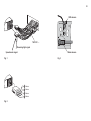
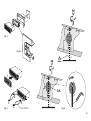
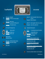
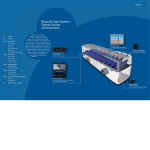
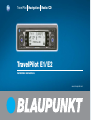
TravelPilot Navigation Radio/CD
TravelPilot E1/E2
Installation instructions
www.blaupunkt.com
Installation instructions
Safety notices
If these instructions are not suitable for
your particular installation, please contact your Blaupunkt dealer, your vehicle manufacturer or our telephone hotline.
Please observe the following safety
notices during installation and whilst
making the connections.
•
Battery voltage 10.5-14.4 V
•
•
Negative terminal on the vehicle body
Disconnect the negative terminal of the
battery! When doing so, please observe the safety notices provided by
the vehicle manufacturer.
•
When drilling holes, always make sure
that none of the vehicle’s components
can be damaged in the process.
•
The cross section of the positive and
negative cables must be at least
1.5 mm2.
Do not connect any of the vehicle’s
plugs directly to the TravelPilot!
•
You can obtain the adapter cables required for your vehicle type from your
Blaupunkt dealer.
•
•
Depending on the vehicle model, the
conditions in your vehicle may differ
from the description provided here. We
do not accept liability for any damages
caused by mistakes made during installation or when making connections
or for any consequential damages.
Notices on correct functioning
To ensure the navigation system functions correctly, it is very important that
you calibrate it after installation (see
operating instructions / Setup - Basic
settings / Installation).
The system uses its connection with the
vehicle’s speedometer signal to determine
the distance driven along the route. If there
is no speedometer signal available, an
odometer must be fitted by an authorized
customer service centre.
In this case, you must purchase a sensor kit (odometer, magnetic strip, installation bracket and plug) from your dealer. Order no. 7 607 611 093
1. Electrical connection
1.1 Electrical connection to the
vehicle-specific plugs
If your car radio connection in your
vehicle has already been fitted at the
factory with 10 A fuse protection (see
operating instructions or your vehicle’s
fuse box), you will additionally need the
vehicle-specific adapter cable (see
Fig. 1).
A vehicle-specific adapter cable
must also be used even in vehicles
that are already fitted with ISO plugs.
2. Loudspeaker connection
2.1 Loudspeaker connection to
standard ISO plug
The loudspeaker connection is made
in chamber B (see Fig. 2).
If the vehicle is prefitted for a passive installation (with 4-ohm loudspeakers), you can convert the ISO
plug that is present in the vehicle. If
required, you can extend it using the
ISO cable (Order no. 7 607 647 093).
If the vehicle is prefitted for an active installation, you can obtain special adapter cables from your dealer.
95
96
3. Antenna installation
3.1 Radio antenna
In the case of vehicles that have been
prefitted (e.g. VW, Seat, Audi), the supply voltage for the antenna is provided
via the antenna cable (see the vehicle’s operating instructions). If you
want to replace the original equipment
radio with a standard radio, you must
obtain an antenna supply diplexer (Order no. 7 691 290 202) or the adapter
cable (Order no. 7 607 621 129) from
your dealer.
You will find details on installing and
connecting the antenna in the antenna installation instructions.
After carrying out the installation, plug
the antenna cable into the socket designated for this on the TravelPilot (see
Fig. 3).
3.2 GPS antenna (satellite navigation)
You will find details on installing and
connecting the antenna in the supplied
antenna installation instructions.
You must take the following into account if installing the GPS antenna inside the vehicle:
The antenna requires a clear view of
as large an area of the sky as possible.
For this reason, the dashboard provides a suitable installation position
directly behind the windscreen, as long
as the windscreen has no metallic coating and the windscreen wipers do not
block the view.
The antenna should be installed in the
middle of the dashboard at a distance
of at least 2 cm from the windscreen.
Note: Despite these recommendations, installing the GPS antenna inside the vehicle is still unfavourable.
For this reason, no guarantee can be
given that the system will function correctly.
After carrying out the installation, plug
the SMB plug into the socket designated for this on the TravelPilot (see
Fig. 3).
4. TravelPilot installation
The TravelPilot is installed in the car
radio compartment designated by the
vehicle manufacturer.
For vehicles that do not have a DIN
compartment: Blaupunkt supplies
vehicle-specific installation kits (for
50/52 mm devices) for the most common vehicle models. Therefore, please
check the situation inside the vehicle
as regards installation and, if necessary, use a vehicle-specific installation
kit to carry out the installation.
4.1 Fitting the installation bracket
The installation bracket that comes
with this TravelPilot allows the TravelPilot to be installed in vehicles fitted
with a DIN-size car radio compartment
(182 x 53 x 165 mm) and a dashboard
thickness near the mounting tabs of
1-20 mm (see Fig. 4). To install, you
must insert the mounting bracket into
the compartment and check which securing tabs on the bracket can be bent
over using a screwdriver (see Fig. 4a).
Note: Bend over as many of the securing tabs as possible.
4.2 Installing the TravelPilot in the
installation compartment
All plugs must be pushed into the
chambers until the side clips click into
place.
Caution! Before inserting the TravelPilot completely, you must first level out
the gyro (see Fig. 6).
Caution! TravelPilot installation position: right / left: min. -5° / max. +5°, front
to back: min. -10° / max. +30°.
Slide the device 1/3 of its length into
the installation compartment.
Undo the gyroscope screw.
Use the hexagonal wrench to adjust
the position of the gyroscope so that
the marker is in a vertical position and
forms a 90° angle with the horizontal.
Tighten the gyroscope screw again.
Now, by gently pressing on both ends
of the frame, push the TravelPilot in
until the side spring latches on the left
and right lock into place (you will hear
a clear clicking sound).
Caution! When pushing in the device,
do not press on the display or any of
the buttons or switches!
4.3 Removing the TravelPilot
Detach the control panel. You must
now insert the stirrups into the designated holes on the left and right of the
surround panel and push them in until
you hear a clear clicking sound (side
springs unlocked). Now carefully pull
on the two stirrups to extract the
TravelPilot. The connecting cables can
now be disconnected by pressing on
the sides of the clips on the respective
plug-and-socket connections (see
Fig. 5).
Note: The clipped in stirrups can only
be detached after the TravelPilot has
been pulled out.
4.4 Connecting the reversing light
signal
Lay a cable from the reversing light to
pin 3 of chamber A (see Fig. 8). You
must make sure that +12 V are present
at the connection when the vehicle reverses.
Note: If it is not possible to connect to
the reversing light, you must connect
pin 3 to earth. This might lead to navigation inaccuracy since the TravelPilot will not be able to detect whether
the vehicle is reversing.
Caution! We do not accept liability for
incorrect connections and their consequences.
4.5 Connecting the speedometer
signal
The connection is made using a cable
from the vehicle-specific speedometer
signal connection to pin 1 of chamber
A (see Fig. 8).
Caution! We do not accept liability for
incorrect connections and their consequences.
5. Sensor test
After carrying out the installation, you
should test the connected sensors using the sensor test (see operating instructions / Setup - Basic settings / Installation).
6. Connection diagrams
Electrical connection to the
vehicle-specific plugs .................
Loudspeaker connection
(4 x 4 Ω/35 W) ...........................
Antenna connection ...................
TravelPilot installation ...............
Removing the TravelPilot ..........
Gyro adjustment ........................
Connection configuration ...........
Assignment of connections,
chamber A. ................................
Fig. 1
Fig. 2
Fig. 3
Fig. 4/4a
Fig. 5
Fig. 6
Fig. 7
Fig. 8
Caution! This connection should be
carried out by one of the vehicle manufacturer’s authorized workshops.
97
98
A
GPS antenna
7 607 621 …
Reversing light signal
Radio antenna
Speedometer signal
Fig. 3
A
Fig. 1
RR
Fig. 2
F LR
RF L
+
+
+
+
-
4 Ohm
4
ohms
4 Ohm
ohms
4 Ohm
ohms
4 Ohm
ohms
Fig. 4
–1 0
°
°
+30
Fig. 4a
90°
1.
1
– 0
°
°
+30
O.K.
2.
3.
Fig. 5
–10 °
2.
3.
8 601 910 003
0°
+3
90°
Fig. 6
99
100
C-1
2
8 11
15 18
A
14 17 20
C
1
2
3
4
5
6
7
8
6
3
4
8
9
C-3
13 16 19
9 12
5
2
1
7
6
3
1
5
C-2
7 10
4
2
D
10
1
3
5
7
4
6
8
1
3
5
7
2
4
6
8
B
A
Gala/speedometer
Telephone mute (active low)
Reversing light signal
Continuous positive (terminal 30)
Autom. antenna*
Illumination
Ignition (terminal 15)
Ground
1
2
3
4
5
6
7
8
Loudspeaker RR+
Loudspeaker RRLoudspeaker RF+
Loudspeaker RFLoudspeaker LF+
Loudspeaker LFLoudspeaker LR+
Loudspeaker LR-
C
C1
1
2
3
4
5
6
Line out LR
Line out RR
Line out GND
Line out LF
Line out RF
+12 V switched*
Equalizer
Telephone / Navigation AF IN +
Telephone / Navigation AF IN –
Radio / Navigation Mute (active low)
+12 V switched*
Remote control - IN
Remote control - GND
1
2
3
4
5
6
7
8
9
10
—
—
—
—
—
—
Sensor
—
Sensor
—
Wheel sensor
C2
7
8
9
10
11
12
D
B
C3
13
14
15
16
17
18
19
20
CDC data - IN
CDC data - OUT
+12 V continuous positive
+12 V switched*
CDC data - GND
CDC AF - GND
CDC AF - L
CDC AF - R
* Sum total 400 mA
Amplifier
Fig. 7
RC 10
CD changer
12V
Relais
Control cable (power antenna +)
The control cable is the switched positive output for external components, e.g. electric antenna (maximum load
< 150 mA).
Caution! You must not connect the control cable to terminal 15 (positive switched) or terminal 30 (continuous positive).
Wheel sensor
(only necessary for vehicles without
a speedometer signal)
A
Positive connection (switched via the ignition)
Terminal 15
+12 V
This connection must be connected in such a way that
it is switched via the ignition (terminal 15, +12 V).
8 604 390 045
Earth/ground connection
Do not connect the earth cable (min. cross section 1.5 mm2)
to the negative terminal of the battery.
Lay the ground cable to a suitable earth connection point
(e.g. a bolt connected to the car body / sheet metal of the
car body) and screw it in place.
Speedometer signal
Illumination connection
Illumination connection for vehicles with an adjustable instrument illumination (regulated positive).
Tel. mute (active low)
12V
Reversing light signal
Fig. 8
Subject to changes!
Continuous positive connection (connection terminal
30, battery +12 V)
Lay the positive cable (cross section min. 1.5 mm2) to the
battery (not directly alongside cable harnesses). Connect
the fuse holder (so as to protect the positive cable) and
then connect it to the positive terminal of the battery.
12V
101
Country:
Germany
Austria
Belgium
Denmark
Finland
France
Great Britain
Greece
Ireland
Italy
Luxembourg
Netherlands
Norway
Portugal
Spain
Sweden
Switzerland
Czech. Rep.
Hungary
Poland
Turkey
(D)
(A)
(B)
(DK)
(FIN)
(F)
(GB)
(GR)
(IRL)
(I)
(L)
(NL)
(N)
(P)
(E)
(S)
(CH)
(CZ)
(H)
(PL)
(TR)
Phone:
Fax:
www:
0180-5000225
01-610 39 0
02-525 5444
44 898 360
09-435 991
01-4010 7007
01-89583 8880
210 94 27 337
01-4149400
02-369 62331
40 4078
023-565 6348
66-817 000
01-2185 00144
902-120234
08-7501500
01-8471644
02-6130 0441
01-333 9575
0800-118922
0212-335 06 00
05121-49 4002
01-610 39 391
02-525 5263
44-898 644
09-435 99236
01-4010 7320
01-89583 8394
210 94 12 711
01-4598830
02-369 62464
40 2085
023-565 6331
66-817 157
01-2185 11111
916-467952
08-7501810
01-8471650
02-6130 0514
01-324 8756
022-8771260
0212-346 00 40
http://www.blaupunkt.com
Blaupunkt GmbH
Printed in Germany
TravelPilot E1/E2
An overview!
NAV
Short press: Navigation
Long press: Traffic jam and route options
FM·AM
Short press: Radio mode,
wavebands FM, MW and LW
Long press: Travelstore function
Radio/CD: Search upwards / Skip to the next track
Navigation: Jump to the selection list
CD·C
CD mode, CD-changer mode
Opening the release panel
Rotate:
Volume control
Short press: Activate mute
Long press: Switch on/off
Rotate:
1
_
6
Radio/CD: Search downwards / Skip to the previous track
Navigation: Delete characters
OK
Station buttons,
Destination memory
TRAF
Short press: Traffic information standby
Long press: View TMC messages
MENU
Setup menu
Short press during a navigation session:
Display your position and the active destination,
Repeat the last voice output
Long press during a navigation session:
Route list
Short press when a navigation session is inactive:
Display your current position,
Display list entries in full
ESC
08/04 CM/PSS2 (GB)
For selecting menus and characters,
manual station tuning
Short press: Confirm menu items
Long press: Scan function
Close menus, delete characters, cancel navigation
8 622 404 132 Index A