1
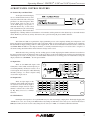
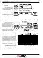
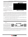
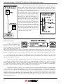
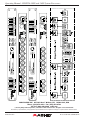
Protea™
4.8SP and 3.6SP
DSP Loudspeaker System Processors
Operating Manual
ASHLY AUDIO INC.
847 Holt Road Webster, NY 14580-9103 Phone: (585) 872-0010
Toll-Free: (800) 828-6308 Fax: (585) 872-0739
ashly.com
Operating Manual - PROTEA™ 4.8SP and 3.6SP System Processors
Important Safety Instructions
Consignes de sécurité à lire attentivement
The lightning flash with arrowhead symbol, within an equilateral triangle,
is intended to alert the user to the presence of uninsulated "dangerous
voltage" within the product's enclosure that may be of sufficient magnitude
to constitute a risk of electric shock to persons. The exclamation point
within an equilateral triangle is intended to alert the user to the presence
of important operating and maintenance instructions in the literature accompanying the device.
Le symbole de la flèche dans un triangle équilateral symbolisant la foudre
est prévu pour sensibiliser l’utilisateur à la présence de tension de voltage
non isolée à l’intérieur de l’appareil. Elle pourrait constituer un danger de
risque de décharge électrique pour les utilisateurs. Le point d’exclamation
dans le triangle équilatérale alerte l’utilisateur de la présence de consignes
qu’il doit d’abord consulter avant d’utiliser l’appareil.
1. Read these instructions.
2. Keep these instructions.
3. Heed all warnings.
4. Follow all instructions.
5. To reduce the risk of fire or electric shock, do not expose this apparatus to
rain or moisture.
6. Do not use this apparatus near water.
7. Clean only with dry cloth.
8. Do not block any ventilation openings. Install in accordance with the manufacturer’s instructions.
9. Do not install near any heat sources such as radiators, heat registers,
stoves, or other apparatus.
10. Do not defeat the safety purpose of the polarized or grounding-type plug. A
polarized plug has two blades with one wider than the other. A grounding type
plug has two blades and a third grounding prong. The wide blade or the third
prong are provided for your safety. If the provided plug does not fit into your
outlet, consult an electrician for replacement of the obsolete outlet.
11. Protect the power cord from being walked on or pinched particularly at plugs,
convenience receptacles, and the point where they exit from the apparatus.
12. Only use attachments/accessories specified by the manufacturer.
13. Use only with the cart, stand, tripod, bracket, or table specified by the
manufacturer, or sold with the apparatus. When a cart is used, use caution when
moving the cart/apparatus combination to avoid injury from tip-over.
14. Unplug this apparatus during lightning storms or when unused for long
periods of time.
15. Refer all servicing to qualified service personnel. Servicing is required when
the apparatus has been damaged in any way, such as power-supply cord or plug
is damaged, liquid has been spilled or objects have fallen into the apparatus, the
apparatus has been exposed to rain or moisture, does not operate normally, or
has been dropped.
1. Lisez ces instructions.
2. Conservez ces instructions.
3. Observez les avertissements.
4. Suivez ces instructions.
5. Pour réduire le risque de feu ou la décharge électrique, ne pas exposer cet
appareil pour pleuvoir ou l'humidité.
6. Ne pas utiliser l’appareil près de l’eau.
7. Le nettoyer à l’aide d’un tissus sec.
8. Ne pas bloquer les ouvertures de ventilation, installer selon les consignes du
fabricant.
9. Eloigner des sources de chaleur tel: radiateurs, fourneaux ou autres appareils
qui produisent de la chaleur.
10. Ne pas modifier ou amputer le système de la mise à terre. Une prise avec
mise à terre comprend deux lames dont une plus large ainsi qu’une mise à
terre: ne pas la couper ou la modifier. Si la prise murale n’accepte pas la fiche,
consulter un électricien pour qu’il remplace la prise désuète.
11. Protéger le cordon de secteur contre tous bris ou pincement qui pourraient
l’endommager, soit à la fiche murale ou à l’appareil.
12. N’employer que les accessoires recommandés par le fabricant.
13. N’utiliser qu’avec les systèmes de fixation,chariots, trépied ou autres, approuvés par le fabricant ou vendus avec l’appareil.
14. Débrancher l’appareil lors des orages électriques ou si inutilisé pendant une
longue période de temps.
15. Un entretient effectué par un centre de service accrédité est exigé si
l’appareil a été endommagé de quelque façon: si il a été exposé à la pluie,,
l’humidité ou s’il ne fonctionne pas normalement ou qu’il a été échappé.
WARNING: THIS APPARATUS MUST BE EARTHED
FCC COMPLIANCE:
This device complies with part 15 of the FCC Rules for class A operation, and is subject to the following two conditions:
1) This device may not cause harmful interference
2) This device must accept any interference received, including interference that may cause undesired operation.
2
Operating Manual - PROTEA™ 4.8SP and 3.6SP System Processors
Table Of Contents
1
2
INTRODUCTION . . . . . . . . . . . . . . . . . . . . . . . . . . . . . . . . . . . . . . . . . . . . . . . . . . . 4
1.1 Audio Features . . . . . . . . . . . . . . . . . . . . . . . . . . . . . . . . . . . . . . . . . . . . . . . . . . . . . 4
1.2 User Interface. . . . . . . . . . . . . . . . . . . . . . . . . . . . . . . . . . . . . . . . . . . . . . . . . . . . . . 4
UNPACKING . . . . . . . . . . . . . . . . . . . . . . . . . . . . . . . . . . . . . . . . . . . . . . . . . . . . . . . . 4
3 AC POWER REQUIREMENTS . . . . . . . . . . . . . . . . . . . . . . . . . . . . . . . . . . . . . . . 4
4
5
FRONT PANEL CONTROL FEATURES . . . . . . . . . . . . . . . . . . . . . . . . . . . . . . 5
4.1 Function Keys and Data Wheel. . . . . . . . . . . . . . . . . . . . . . . . . . . . . . . . . . . . . . . . . 5
4.2 Presets. . . . . . . . . . . . . . . . . . . . . . . . . . . . . . . . . . . . . . . . . . . . . . . . . . . . . . . . . . . . 5
4.3 Input Select. . . . . . . . . . . . . . . . . . . . . . . . . . . . . . . . . . . . . . . . . . . . . . . . . . . . . . . . 5
4.4 Output Select. . . . . . . . . . . . . . . . . . . . . . . . . . . . . . . . . . . . . . . . . . . . . . . . . . . . . . . 5
4.5 LED Indicators. . . . . . . . . . . . . . . . . . . . . . . . . . . . . . . . . . . . . . . . . . . . . . . . . . . . . 5
4.6 Audio Functions . . . . . . . . . . . . . . . . . . . . . . . . . . . . . . . . . . . . . . . . . . . . . . . . . . . . 6
4.6a Gain . . . . . . . . . . . . . . . . . . . . . . . . . . . . . . . . . . . . . . . . . . . . . . . . . . . . . . . . . . 6
4.6b EQ . . . . . . . . . . . . . . . . . . . . . . . . . . . . . . . . . . . . . . . . . . . . . . . . . . . . . . . . . . . 6
4.6c Delay . . . . . . . . . . . . . . . . . . . . . . . . . . . . . . . . . . . . . . . . . . . . . . . . . . . . . . . . . 7
4.6d Crossover. . . . . . . . . . . . . . . . . . . . . . . . . . . . . . . . . . . . . . . . . . . . . . . . . . . . . . 8
4.6e Limit. . . . . . . . . . . . . . . . . . . . . . . . . . . . . . . . . . . . . . . . . . . . . . . . . . . . . . . . . 10
4.7 Other Functions. . . . . . . . . . . . . . . . . . . . . . . . . . . . . . . . . . . . . . . . . . . . . . . . . . . . 10
4.7a Recall. . . . . . . . . . . . . . . . . . . . . . . . . . . . . . . . . . . . . . . . . . . . . . . . . . . . . . . . 10
4.7b Save. . . . . . . . . . . . . . . . . . . . . . . . . . . . . . . . . . . . . . . . . . . . . . . . . . . . . . . . . 11
4.7c Copy. . . . . . . . . . . . . . . . . . . . . . . . . . . . . . . . . . . . . . . . . . . . . . . . . . . . . . . . . 11
4.7d Mute. . . . . . . . . . . . . . . . . . . . . . . . . . . . . . . . . . . . . . . . . . . . . . . . . . . . . . . . . 11
4.7e Utilities. . . . . . . . . . . . . . . . . . . . . . . . . . . . . . . . . . . . . . . . . . . . . . . . . . . . . . . 11
4.7f Factory Reset. . . . . . . . . . . . . . . . . . . . . . . . . . . . . . . . . . . . . . . . . . . . . . . . . . 11
INTERCONNECT FEATURES . . . . . . . . . . . . . . . . . . . . . . . . . . . . . . . . . . . . . . . 12
5.1 Audio Connections. . . . . . . . . . . . . . . . . . . . . . . . . . . . . . . . . . . . . . . . . . . . . . . . . 12
5.2 USB Connection. . . . . . . . . . . . . . . . . . . . . . . . . . . . . . . . . . . . . . . . . . . . . . . . . . . 12
5.3 RS-232 Data Connection . . . . . . . . . . . . . . . . . . . . . . . . . . . . . . . . . . . . . . . . . . . . 12
6 PROTEA NE SOFTWARE . . . . . . . . . . . . . . . . . . . . . . . . . . . . . . . . . . . . . . . . . . . 12
7 TROUBLESHOOTING . . . . . . . . . . . . . . . . . . . . . . . . . . . . . . . . . . . . . . . . . . . . . . 14
8 SPECIFICATIONS . . . . . . . . . . . . . . . . . . . . . . . . . . . . . . . . . . . . . . . . . . . . . . . . . . 14
9 WARRANTY INFORMATION . . . . . . . . . . . . . . . . . . . . . . . . . . . . . . . . . . . . . . . 15
10 BLOCK DIAGRAM . . . . . . . . . . . . . . . . . . . . . . . . . . . . . . . . . . . . . . . . . . . . . . . . . 16
3
Operating Manual - PROTEA™ 4.8SP and 3.6SP System Processors
1. INTRODUCTION
Thank you for your purchase of this Ashly Protea 4.8SP or 3.6SP Digital Crossover/System Processor. The Protea series builds on the tradition of quality and value which has earned Ashly its place as a
market leader in crossovers, equalization, and signal processing.
The 4.8SP has four inputs and eight outputs, while the 3.6SP has three inputs and six outputs. The
front panel interface allows quick access to all control parameters by offering dedicated function buttons,
eliminating the need for hidden sub-menus. For even faster set-ups and stronger visualization of Input/
Output routing, EQ, and Filter curves, a USB port is provided for use with Windows™ Protea NE Software.
Full control by third party controllers is also available via RS-232.
1.1 AUDIO FEATURES
The Protea 4.8SP and 3.6SP utilize state of the art DSP technologies, beginning with 24 bit, 48kHz delta-sigma A/D
converters with 128x oversampling. Digital processing includes Gain, Parametric EQ, Shelving Filters, Time Delay, Crossover
Functions, Compression, Limiting, and Matrix Routing, all taking place in twin 120MHz Motorola DSP56362 high performance
DSP processors. D/A conversion uses 24 bit delta-sigma converters with 128x oversampling. All inputs and outputs are precision
balanced and RF protected using XLR connectors.
1.2 USER INTERFACE
Front Panel Interface: A backlit 2 x 20 character LCD displays channel and function settings. Dedicated buttons
provide access to all audio functions and system tools. The display indicates the current preset number, then subsequently shows
the selected input or output and its active control parameters. Five segment LED arrays on each input and output provide audio
level information and mute status.
Protea NE Software: The computer interface uses Ashly PROTEA NE SOFTWARE for Windows, which allows
complete PC control of the unit through a USB jack. Protea NE software is supplied with each unit, or can be downloaded at
no cost from the Ashly web site. Advantages of using the software include greater preset capacity, and a very intuitive visual
representation of the audio routing and control process.
2. UNPACKING
As a part of our system of quality control, every Ashly product is carefully inspected before leaving the factory to
ensure flawless appearance. After unpacking, please inspect for any physical damage. Save the shipping carton and all packing
materials, as they were carefully designed to minimize the possibility of transportation damage should the unit again require
packing and shipping. In the event that damage has occurred, immediately notify your dealer so that a written claim to cover the
damages can be initiated. The right to any claim against a public carrier can be forfeited if the carrier is not notified promptly
and if the shipping carton and packing materials are not available for inspection by the carrier. Save all packing materials until
the claim has been settled.
3. AC POWER REQUIREMENTS
Note: The AC power switch is on the back panel. The Protea 4.8SP and 3.6SP use a universal input power supply
which will accept any line voltage in the range of 100VAC to 240VAC, 50-60Hz. A standard IEC-320 grounded AC inlet is
provided on the rear panel to accept the detachable power cord. Never remove the AC earth ground connection to the unit.
In the event of fuse failure, refer the product to a qualified service technician for fuse replacement, replacing only with the same
type and rating fuse.
4
Operating Manual - PROTEA™ 4.8SP and 3.6SP System Processors
4. FRONT PANEL CONTROL FEATURES
4.1 Function Keys and Data Wheel
To the right of the LCD display
are two unlabeled function keys and a
rotary data wheel. All audio and system
parameters are edited using these three
controls. Each of the two lines of text
on the LCD display correspond to a
dedicated function key, so that various
tasks on both lines may be selected using
their respective keys. The selected task is
highlighted by a flashing underscore beneath the word or number, and the parameter is then adjusted up or down with the data
wheel. The Esc key will exit any activity and return to the top level showing the preset number and name.
4.2 Presets
The 4.8SP and 3.6SP are organized into 30 programmable presets, each completely defining the configuration of all
inputs and outputs along with their respective audio components. There are ten repeating preset configurations pre-loaded into
the unit which are simply starting points for common applications, and all can be modified, renamed, and saved to suit the end
user. Please Note: In addition to the 30 preset numbers, a constantly refreshed Working Preset is used to take a "snapshot" of
all current settings should the unit be turned off before changes can be saved.
When the unit is first powered up, the last working preset is loaded, displaying the number and name last used before
the unit was turned off. Any modifications made to that preset before saving it will remain in the working preset until either the
modified preset is saved, or a fresh preset is recalled. When modifications to an existing preset are made without saving, the
display adds the text (modified) after the preset number.
4.3 Input Select
There are four XLR audio inputs on the
4.8SP (three on the 3.6SP), and each input is processed independently and may be routed to one or
several outputs. Select an input to edit its Gain, EQ,
and Delay settings, or to mute it. Signal routing
occurs in the output section.
4.4 Output Select
There are eight outputs on the
4.8SP (six on the 3.6SP), and each output
can obtain its source from any input or
combination of inputs. Select an output
channel to edit its Source, Gain, Polarity, EQ, Delay, Crossover, or Limiter
functions.
4.5 LED Indicators
Each input and output has a five segment LED array for audio level display, ranging from -20 through clipping. The
-20 LED is two-color, also serving as the Mute indicator by turning red. The meter scale is factory set so that 0 on the meter is
0dBu (0.775Vrms), however it can be easily changed to VU scale (0 = +4dBu, or 1.228Vrms) within the Util menu.
5
Operating Manual - PROTEA™ 4.8SP and 3.6SP System Processors
4.6 Audio Functions
4.6a Gain
Input and Output Gain are
separately adjustable from -40dB to
+12dB in 0.1dB increments.
The output gain menu also
provides for selection of input source(s)
for a given output channel, as well as polarity of the outgoing signal. Any input
or combination of inputs can be routed
to any or all outputs. Keep in mind that
two signals which share significant
content, such as a stereo source, will
be up to 6dB louder when combined.
4.6b EQ
The Protea SP EQ section offers full parametric EQ as well as 1st
and 2nd order shelving filters on inputs
and outputs. Each input channel has six
selectable EQ filters, while each output
channel has four selectable EQ filters. In
all cases, each filter is selectable between
parametric (PEQ), 1st order Low Shelf
(LS1), 2nd order Low Shelf (LS2), 1st
order High Shelf (HS1), and 2nd order
High Shelf (HS2).
Shelving EQ filters: 1st order filters use
a gentle 6dB per octave slope, while 2nd order
filters use a 12dB per octave slope for more a
pronounced boost or cut. All shelving filters have
a boost/cut range of +/-15dB. Low shelving filters
have a frequency range from 19.7Hz through
2kHz, and the high shelving filters range from
3.886kHz through 21.9kHz. Shelving filters are
most useful as broad tone controls to boost or
cut the high end or low end of an audio signal's
frequency content. Because they affect a wider
spectrum of audio, they are not as suitable for
feedback control as parametric filters.
Parametric EQ (PEQ) uses peak filters
with the ability to control boost or cut, frequency
center, and bandwidth. Think of one band of
parametric EQ as a single graphic equalizer fader except that the frequency is variable, not fixed, and that the bandwidth, or
how "wide" the filter affects the frequency spectrum at the center frequency, is completely variable. The smaller the bandwidth,
the less the audio signal on either side of the frequency center is boost or cut, whereas a larger "wider" bandwidth produces an
6
Operating Manual - PROTEA™ 4.8SP and 3.6SP System Processors
audible change to the overall tone of a signal.
Parametric filters are best used to hunt down
and eliminate problem feedback frequencies,
add or remove a characteristic "hot spot" from
microphones, or clean up room resonance situations. It is well worth the time getting proficient
with parametric EQ filters, as they offer the best
solution to many EQ problems.
Protea SP parametric filters have a
boost/cut range of +15dB to -30dB. There is
more cut than boost because one of the more
common uses for parametric filters is to dramatically cut, or "notch out", very narrow frequencies
(low bandwidth) in order to eliminate system
feedback problems.
Every instance of a parametric EQ filter has a center frequency selected. The factory default is 1kHz, but each filter's
center frequency is adjustable from 19.7Hz to 21.9kHz in 1/24 octave steps. Carefully sweeping a narrow bandwidth filter through
a problem feedback area, with just a slight boost, is a quick way to find the exact frequency causing trouble. Once the offensive
frequency has been found, cut the filters level, and then the bandwidth is adjusted as narrow as possible while still eliminating
the feedback problem. Bandwidth is adjustable from about 1/64 octave to four octaves, and the lower the bandwidth, the less
audible the filter action will be. Finding the problem frequency is relatively easy, but finding the best combination of cut and
bandwidth takes a little practice. Again, it is well worth the time becoming comfortable with the notching procedure, so that
problems can be quickly addressed with a sufficient but minimal amount of correction.
The EQ functions on all four inputs and eight outputs are switched in or out on an individual channel basis. In other
words, each input or output has one "switch" for all of its EQ filters. If certain filters are not going to be used within a channel,
simply leave the gain for that filter at 0.0dB, and the filter will have no effect.
For an excellent interactive display of the way parametric and shelving filters work, experiment with the 4.8SP or 3.6SP
EQ section of Protea NE Software. The software works whether a unit is connected or not, so it is an invaluable teaching tool as
well as an audio setup tool for Protea products. The program is shipped with SP units, but is also available on the Ashly web site.
4.6c Delay
In large installations or outdoor
venues there are often many speaker
clusters in various locations to get the
best coverage possible. Since sound travels relatively slow through air (1130 ft/s
at 20ºC), multiple loudspeaker locations
can create a situation where the original
audio signal, simultaneously leaving all
loudspeakers, arrives at a single point in the venue at several different times. Needless to say this causes problems, and what may
be crystal clear sound directly in front of any one loudspeaker can be unintelligible in the farther reaches of the venue with direct
line-of-sound to multiple loudspeakers. The solution is to delay the audio signal to the loudspeakers located beyond the main
stage area, so that sound comes out of the distant loudspeakers at the exact time that sound from the main stage loudspeakers
arrives. Within the Protea SP, up to 682 milliseconds of time delay are available, allowing secondary loudspeaker clusters to be
time aligned with the primary speakers up to 771 feet (235m) away from the main stage area.
7
Operating Manual - PROTEA™ 4.8SP and 3.6SP System Processors
Output channels have time delay as well. Output delay is best used to align discrete
drivers within a speaker cabinet or cluster, normally quite close together. For example, a
typical three way speaker cluster would have low end, midrange, and high frequency drivers
all located near one another. The different drivers for each frequency band are not necessarily
the same physical depth with respect to the front of
the loudspeaker cluster, so there exists the problem
of same signals (at the crossover points) arriving
at the cluster "front" at different times, creating
undesirable wave interaction and frequency cancellation. The solution, again, is to slightly delay
the signal to the drivers closest to the cluster front.
Using the location of the driver diaphragm farthest
back as a reference point, measure the distance to
other drivers in the cluster, and set the output delay
for each accordingly, with the driver diaphragm
closest to the front getting the longest delay and
the driver at the very back getting no output delay.
Note: Although delay in the SP is adjusted only by
time, the corresponding distance in both feet and
meters is always shown as well.
4.6d Crossover (Xover)
Crossover functions are available only on the output channels. Every
channel's crossover consists of a high
pass filter (HPF) and a low pass filter
(LPF), along with the frequencies and
filter types used. Each output's crossover section is essentially a bandpass filter, making it necessary for the user to map out ahead
of time which outputs will be used for the various frequency bands, and set the overlapping filter frequencies and types accordingly. Note: The HPF determines the lower frequency limit of the signal, while the LPF determines the upper frequency limit.
The frequency range for the high pass filter (HPF) is from 19.7Hz to 21.9kHz, with an option to turn the filter off at
the low end of the frequency selection. The low pass filter (LPF) offers the same frequency range, with the "off" option at the
high end of the frequency selection.
There are 11 types of filters available in the crossover section, each suited to a specific preference or purpose. The slope
of each filter type is defined by the first characters in the filter type, 12dB, 18dB, 24dB, or 48dB per octave. The steeper the slope,
the more abruptly the "edges" of the pass band will drop off. There is no best filter slope for every application, so experiment
to see which one sounds most pleasing in a specific system. Ashly factory default presets use all 24dB/octave Linkwitz-Riley
filters in the crossover section, but of course they can be changed to suit the application.
In addition to the frequency and slope, crossover filters can be selected as having Butterworth, Bessel, or Linkwitz-Riley
response. These refer to the shape of a filter's slope at the cut-off frequency, affecting the way two adjacent pass bands interact
at the crossover point. 24db/octave Linkwitz-Riley filters produce a flat transition through the crossover region, assuming both
overlapping filters are set to the same frequency, slope, and response type. 24dB/oct Linkwitz-Riley filters are the industry
standard, the easiest to use, and the filter type recommended by Ashly. Other filter types are available, but may require polarity
switching or other adjustments for proper results. The following paragraphs offer a summary of the three filter types as used in
4.8SP and 3.6SP crossovers:
8
Operating Manual - PROTEA™ 4.8SP and 3.6SP System Processors
Butterworth
Butterworth filters individually are always -3dB at the displayed crossover frequency and are used because they have
a "maximally flat" passband and sharpest transition to the stopband. When a Butterworth HPF and LPF of the same crossover
frequency are summed, the combined response is always +3dB. With 12dB per octave Butterworth crossover filters, one of the
outputs must be inverted or else the combined response will result in a large notch at the crossover frequency.
Bessel
These filters, as implemented on the SP processors, are always -3dB at the displayed crossover frequency. Bessel filters
are used because they have a maximally flat group delay. Stated another way, Bessel filters have the most linear phase response.
When a Bessel HPF and LPF of the same crossover frequency are summed, the combined response is +3dB for 12dB/oct, 18dB/
oct, and 48dB/oct Bessel filters, and -2dB for 24dB/oct Bessel filters. One of the outputs must be inverted when using either
12dB/oct or 18dB/oct Bessel crossover filters or else the combined response will have a large notch.
Linkwitz-Riley
The 12 dB/oct, 24dB/oct and 48dB/oct Linkwitz-Riley filters individually are always -6dB at the displayed crossover
frequency, however the 18dB/oct Linkwitz filters individually are always -3dB at the displayed crossover frequency. The reason
for this is that Linkwitz-Riley filters are defined in terms of performance criterion on the summing of two adjacent crossover
HPF and LPF filters, rather than defined in terms of the pole-zero characteristics of individual filters. The 18dB/oct LinkwitzRiley individually are 18dB/oct Butterworth filters in that they have Butterworth pole-zero characteristics and also satisfy the
criterion for Linkwitz-Riley filters.
When a Linkwitz-Riley HPF and LPF of the same displayed crossover frequency are summed, the combined response
is always flat. With 12dB/oct Linkwitz-Riley crossover filters, one of the outputs must be inverted or else the combined response
will have a large notch at the crossover frequency.
4.6e Limit
A full function compressor/limiter is included on each output channel. A limiter is commonly used to prevent transient audio signal spikes from damaging
loudspeakers, manage analog and digital
recording levels, optimize broadcast
levels, or "thicken" the sound of an
audio source (compression). The adjustable parameters include Limiter In/Out,
Limiter Threshold, Ratio, Attack Time,
and Release Time.
The 4.8SP and 3.6SP limiter threshold range is from -20dBu to
+20dBu. This setting determines the
signal level above which gain reduction begins, and is indicated by the yellow LED (Lim) in the output meter section. Increases
in audio level above the threshold will be reduced according to the ratio settings.
The ratio control determines the amount of gain reduction above limiter threshold. Ratio ranges from a gentle 1.2:1 to
a brick-wall INF:1. To illustrate how the ratio control works, imagine a commonly used loudspeaker protection ratio of 10:1,
which means that for every input signal increase of 10 dB above threshold, the output level will only increase by 1dB. The higher
the ratio, the more pronounced the audio effect, so use the lowest ratio possible to sufficiently address the problem.
Attack (A__ms) and Release (R__ms) settings adjust the time it takes the limiter to engage and then disengage when
the signal increases above threshold and then subsequently falls back below threshold. Attack time is adjustable from 0.5ms
through 50ms, while release time ranges from 10ms through 1s. A very fast attack time can sound unnatural, while a very long
attack time can miss some of the initial transient. Similarly, a very short release time can make the audio sound uneven, while a
very long release time can create "pumping", or "breathing" characteristics depending on the kind of signal. Experiment to find
the best solution for a given application.
9
Operating Manual - PROTEA™ 4.8SP and 3.6SP System Processors
4.7 Other Functions
The Protea 4.8SP and 3.6SP have a full complement of non-audio functions within a single keystroke to navigate
around the product quickly. Recall, Save, Copy, Mute, and a Utilities menu complete the user friendly interface Protea products
are known for.
4.7a Recall
There are 30 stored presets which can be recalled on the SP processor. Note: A preset recall will overwrite the working
settings, so make sure the current configuration is saved before continuing or it will be lost. Remember, an unsaved working
preset shows (modified) on the preset name screen. Press Esc to see the preset name screen. The unit always loads the working
preset on power-up, so as to preserve any changes should the power be inadvertently turned off prior to saving.
Ashly has included ten preset templates as starting points for common 4.8SP or 3.6SP configurations, and these preset
templates repeat as they scroll through the 30 presets. To recall a new preset, press the recall button once, select the desired
preset number, and press recall again. At this point the LCD display prompts the user to mute the outputs or not, and selecting
Yes or No will load the new preset and mute all outputs if so desired. A new preset may have dramatically different settings
capable of damaging sound system components, so be careful not to recall the wrong preset while the system is on. To be safe,
always select "Yes" to mute all outputs.
4.7b Save
Once the unit has been adjusted to suit the application, the changes can be permanently saved to memory*. To save a
new configuration or save changes to an existing preset template, begin the process by pressing the Save button once. The LCD
display prompts for the new (or same) preset number, and after selecting the desired number press Save again. At this point the
name of the preset can be changed by selecting any one of the 20 text characters and scrolling through the list of 89 available
ASCII characters for each. Pressing the Save button again permanently stores the working preset to the new preset location.
*Note: performing a Factory Reset will erase all user presets and replace them with the ten original Ashly preset
templates. User defined presets can be stored off-line as files using Protea NE Software.
4.7c Copy
The Copy function is used to quickly transfer all settings from a currently selected input or output to another input or
output channel. An example of how this might be used is with stage monitors. Suppose there are eight monitor mixes on stage,
and they all use the same type of floor wedge. The first monitor could be set up with Gain, EQ, and Limiting, then those settings
could be quickly copied to the remaining seven monitors, providing a consistent starting point for each mix. To copy, first select
the input/output to copy from, then press the Copy button, then press the input/output to copy to, pressing the Copy button a
second time to complete the action.
4.7d Mute
The Protea 4.8SP and 3.6SP allow the user to mute both inputs and/or outputs. When muted, an input or output's red
Mute LED is lit. When an input or output is selected, pressing the Mute button will toggle its mute function. To quickly mute
all outputs, escape out to the top level preset display, then press the Mute button, pressing it a second time to confirm. Additionally, when recalling a new preset number to the unit, the LCD display prompts the user to mute all outputs, as a new preset can
introduce dramatic changes to the system configuration.
10
Operating Manual - PROTEA™ 4.8SP and 3.6SP System Processors
4.7e Util
The Protea 4.8SP and 3.6SP
utilities include a security section for
password protected lockout, a dBu/VU
meter preference select, and a device
name display.
Security
There are four security modes in the 4.8SP and 3.6SP: Off, Preset Lock, Parameter Lock, and Full Lockout. When
connected to a PC via the USB port, security settings made on the SP unit are read and used within the Protea NE software
security section, sharing the same passcode.
1.) Off (none) allows full access to all controls.
2.) Preset Lock allows full access while disabling the save function.
3.) Parameter Lock allows the user to recall different presets, but allows no changes other than mute.
4.) Full Lockout allows absolutely no local changes, but allows viewing of current settings.
To access the security menu, first press the Util button, then select the Security display line on the LCD. Use the data
wheel to select from the four security levels. If the unit is brand new and has never had a security code, or has had a factory
reset, a four digit code must first be entered before changing security status. Use the output select buttons 1-8 (recommended)
or the data wheel (0-9) to enter a new code, then press Enter on the LCD. The LCD then prompts the user to either change the
code to a new four digit number, or change the Security status to one of the other three options.
The only way to fully remove a security code once it has been entered is with a factory reset. This is done by turning the
power on while pressing Esc and Recall together, returning all settings, including user defined presets, to their original factory
settings. Note: In the event the four digit security code is forgotten, turn the unit on while pressing both the Esc and Util buttons.
dBu/VU Meter Select
The input and output meter scale is factory set so that a green LED flashing at 0 indicates a signal level of 0dBu, or
0.775Vrms. To change this to a VU scale, where 0VU = +4dBu (1.228Vrms), select the <Ref:> option in the Util menu to VU.
Note: Protea NE software for the 4.8SP and 3.6SP can only display LED meters in dBu.
Device Name
The device name is assigned from within Protea NE software, and is displayed in the LCD window.
4.7f Factory Reset
To clear all preset names, reset all controls to their original factory settings, and delete the password from memory,
Factory Reset may be performed by simultaneously pressing and holding Esc and Recall while switching power on. Caution:
doing this will erase all user-defined presets!
11
Operating Manual - PROTEA™ 4.8SP and 3.6SP System Processors
5. INTERCONNECT FEATURES
5.1 Audio Connections
All Protea audio connections use three pin XLR jacks, with pin 2 (+), pin 3 (-), and pin 1(G). Inputs and outputs are
electronically precision balanced. If an unbalanced signal is fed to an input, the signal should be on the (+) connection (pin 2)
and pin 3 must be tied to ground, or significant signal loss will result. In other words, never float pin 2 or pin 3. It is strongly
recommended that balanced signals be used whenever possible.
A Note About Input Signal Levels:
There are no analog gain trim adjustments on the Protea SP unit, therefore all the processing (including gain) is done
in the digital domain. As a consequence of this design philosophy, it is important to feed the Protea processor with the proper
nominal signal level to achieve good signal to noise performance as well as headroom before clipping. This unit is designed to
clip at signal levels above +20dBu = 7.75Vrms which places the noise floor lower than -90dBu. The optimum input signal level
which should be fed into the Protea processor is 0dBu = .775Vrms. This input level will allow 20dB of headroom while giving
a nominal signal that is >90dB above the noise floor.
5.2 USB Connection
There are two USB ports on the SP unit, one on the front and one on the back panel. They both serve
the same function, but a front panel USB connection will always override the back panel USB port if both are
being used simultaneously. A six foot USB-A to USB-B cable is provided with every Protea SP unit to connect
to a computer running Ashly Protea NE software.
5.3 RS-232 Data Connections
Several third party controllers use RS-232 for control of other devices which may include the Protea
SP processors. For detailed information regarding the implementation of RS-232 control, contact the Ashly
service department. Note: Protea NE software will not work with a 4.8SP or 3.6SP processor using RS-232.
The computer connection must use a USB port.
6. PROTEA NE SOFTWARE
Loading the software
Ashly Protea NE software is included on a CD with each unit. Check the Ashly web site at www.ashly.com to verify
that you are installing the latest software release. Autorun will launch the application<ProteaSystemSoftwareNE> to install the
Protea software.
Connect the SP processor
The control connection is made using a standard USB-A to USB-B cable, provided by Ashly with each unit.
Identify the processor in software
Once the software is loaded to the computer and the data connection has been made to the 4.8SP or 3.6SP, all installed
NE software compatible Ashly products will be automatically detected and shown in the active device listing on the left side of
the Protea NE software startup canvas. Note: In the event of multiple processors of the same model on the network, the user can
find a single physical unit by right clicking over the unit’s name in the drop down menu, and then click <Identify>, which will
flash the Com LED on that unit’s face panel for two seconds.
The software scans for active devices on power-up, but the user can manually scan at any time as well with <Scan For
Devices> at the bottom of the network device listing. All Ashly devices continuously broadcast their availability to the software.
All currently connected and active products are highlighted in green, while units which may be or have been formerly installed
but are currently off-line or unavailable show up in red. Individual products can be dragged onto the project canvas to simulate
physical rack installation groups, but editing each product can be done from either the product list or the image on the canvas.
12
Operating Manual - PROTEA™ 4.8SP and 3.6SP System Processors
The NE software project canvas
The project canvas is used to visually represent and control a fixed physical sound system installation, and can display
any of the Ashly processors, amplifiers, and remotes used in that system. The user can also place an assortment of isolated control objects such as level faders, single LEDs, meter bars, etc, and map them to specific product functions within that project.
Once a control object is placed, right click on it to bring up its properties. Additionally, lines, rectangles, text, and even image
files can be added to create a custom virtual control screen along with the Ashly products and individual control objects. To see
all available canvas tools, right click anywhere over open canvas. Checking <Design Mode> allows placed objects to be moved
around, while unchecking <Design Mode> locks objects in place
Meters
Inputs and outputs each have real-time virtual meter displays, shown in dBu only. Output compressor/limiters have
meter displays shown in dB.
Presets Options
The 4.8SP or 3.6SP will store up to 30 total presets. A preset file takes a “snapshot” of all current settings and stores
complete control data for all channels and all audio functions. In addition to pressing the Save button on the face panel, individual
presets can be saved to the processor by using <Preset Options/Save Preset To Protea>, or saved to a PC using <Preset Options/
Save To Disk>. Preset files for Ashly SP products use the extension (*.pne).
In addition to the face panel preset recall button, a preset can be recalled in software from either a computer or from
the processor’s internal memory. Caution: A new preset may have dramatically different settings capable of damaging sound
system components, so be careful not to recall the wrong preset while the system is on.
The Protea 4.8SP and 3.6SP are similar to the older Ashly Protea 4.24C and 3.24CL models respectively. An existing
preset file from the older *.pcc format can be loaded onto the new SP unit using <Preset Options/Load 4.24C Preset From Disk>.
Security
The 4.8SP and 3.6SP processors have front panel security options within the utilities menu. Additionally, Protea NE
software offers independent management of the front panel security as well as software security. The password will be the same
in software as it is on the physical unit.
13
Operating Manual - PROTEA™ 4.8SP and 3.6SP System Processors
7. TROUBLESHOOTING
7.1 - Audio Troubleshooting Tips
No power - Is the detachable AC cord fully plugged in? Is the rear panel power switch on?
Controls don't work - check the Security Level. If set to Full Lockout, then Protea unit is "view only". Change security
settings in Util menu or software.
No sound - Check to see if the input or output is muted. Is the input or output Gain turned down? Check the selected
audio source(s) for each output, making sure there is signal applied to the designated input(s). If the crossover is used, make
sure the high pass filter (HPF) is set to a lower frequency than the low pass filter (LPF).
Clip light stays on - Is the input signal level too high? Check to see that the nominal input level is 0dBu, allowing 20dB
of input headroom. Are input or output gain settings too high? Check to see if an EQ filter has too much boost.
Distorted sound but no Clip LED- Check individual EQ filters to see if there is excessive boost.
Muffled sound - If expecting full range audio on an output, make sure the crossover settings are not inadvertently set
so as to limit the pass band.
Excessive Noise - An input signal level or an input gain setting that is too low could require the loss to be made up for
at the output gain stage, producing more noise than a properly set up gain structure. Do not use the DSP processor section for
dramatic increases in level, but rather optimize the signal source for a nominal 0dBu output.
Forgot the password - See section 4.7e
8. SPECIFICATIONS
Input . . . . . . . . . . . . . . . . . . . . . . . . . . . . . . Active Balanced, 18KΩ
Max. Input Level . . . . . . . . . . . . . . . . . . . . +20dBu
Input Gain Range . . . . . . . . . . . . . . . . . . . -40dB to +12dB
Output . . . . . . . . . . . . . . . . . . . . . . . . . . . . . Active Balanced, 112Ω
Max. Output Level . . . . . . . . . . . . . . . . . . . +20dBu
Output Gain Range . . . . . . . . . . . . . . . . . . -40dB to +12dB
EQ
EQ Filter Types . . . . . . . . . . . . . . . . . . . . .
Shelving Filter Boost/Cut Range . . . . . . .
Shelving Filter Frequency Range . . . . . . .
Parametric Filter Boost/Cut Range . . . . .
Parametric Filter Frequency Range . . . .
Parametric Filter Bandwidth . . . . . . . . . .
1st or 2nd Order High or Low Shelf, Parametric
±15dB
Low Shelf 19.7Hz to 2kHz, High Shelf 3.8kHz to 21.9kHz
+15dB/-30dB
19.7Hz to 21.9kHz, 1/24 Octave Steps
Four Octaves to 1/64 Octave
Input and Output Delay . . . . . . . . . . . . . . 0-682 milliseconds
Crossover
HPF and LPF Frequency Range . . . . . . .
Available Filter Types . . . . . . . . . . . . . . . .
14
19.7Hz to 21.9kHz, Off
12dB/Oct Butterworth, 12dB/Oct Bessel, 12dB/Oct Linkwitz-Riley
18dB/Oct Bessel, 18dB/Oct Linkwitz-Riley
24dB/Oct Butterworth, 24dB/Oct Bessel, 24dB/Oct Linkwitz-Riley
48dB/Oct Butterworth, 48dB/Oct Bessel, 48dB/Oct Linkwitz-Riley
Operating Manual - PROTEA™ 4.8SP and 3.6SP System Processors
Limiter
Threshold Range . . . . . . . . . . . . . . . . . . . .
Ratio Range . . . . . . . . . . . . . . . . . . . . . . . .
Attack Time Range . . . . . . . . . . . . . . . . . .
Release Time Range . . . . . . . . . . . . . . . . .
-20dBu to +20 dBu
1.2:1 to INF:1
0.5ms to 50ms
10ms to 1 Second
Frequency Response . . . . . . . . . . . . . . . . .
THD . . . . . . . . . . . . . . . . . . . . . . . . . . . . . .
Dynamic Range . . . . . . . . . . . . . . . . . . . . .
Audio Sampling Rate . . . . . . . . . . . . . . . .
Propagation Delay . . . . . . . . . . . . . . . . . . .
Signal LEDs & Clip . . . . . . . . . . . . . . . . . .
AC Requirements . . . . . . . . . . . . . . . . . . .
Environmental . . . . . . . . . . . . . . . . . . . . . .
Weight . . . . . . . . . . . . . . . . . . . . . . . . . . . . .
Dimensions . . . . . . . . . . . . . . . . . . . . . . . . .
20Hz to 20KHz, ±0.25dB
<0.01% @ 1KHz, +20dBu
>110dB 20Hz - 20KHz unweighted
48KHz
1.46mS
Inputs: -20/Mute, -10, 0, +10, Clip (dBu or VU)
Outputs: -20/Mute, -10, 0, Limit Threshold, Clip (dBu or VU)
Universal Power Supply, 100-240VAC, 50/60Hz, 20W max
40°F - 120°F (4°C-49°C) Non-condensing
9 Lbs
19.0” L x 1.75” H x 8.5” D (48.3 cm x 8.9 cm x 21.6 cm)
9. ASHLY AUDIO INC Limited Warranty (USA ONLY)
(Other countries please contact your respective distributor or dealer)
For units purchased in the USA, warranty service for this unit shall be provided by ASHLY AUDIO, INC. in accordance with the following warranty statement:
ASHLY AUDIO, INC. warrants to the owner of this product that it will be free from defects in workmanship and materials for a period of FIVE years
from the original date of purchase. ASHLY AUDIO INC. will without charge, repair or replace at its discretion any defective product or component parts upon
prepaid delivery of the product to the ASHLY AUDIO, INC. factory service department, accompanied with a proof of original date of purchase in the form of
a valid sales receipt. This warranty gives you specific legal rights, and you may also have other rights, which vary from state to state.
EXCLUSIONS: This warranty does not apply in the event of misuse, neglect or as a result of unauthorized alterations or repairs made to the product.
This warranty is void if the serial number is altered, defaced, or removed. ASHLY AUDIO reserves the right to make changes in design, or make additions to,
or improvements upon this product, without any obligation to install the same on products previously manufactured.
Any implied warranties which may arise under the operation of state law shall be effective only for FIVE years from the original date of purchase of
the product. ASHLY AUDIO, INC. shall be obligated to only correct defects in the product itself. ASHLY AUDIO, INC. is not liable for any damage or injury
which may result from or be incidental to or a consequence of such defect. Some states do not allow limitations on how long an implied warranty lasts, or the
exclusion, or limitation of incidental or consequential damages, so the above limitations or exclusions may not apply to you.
OBTAINING WARRANTY SERVICE:
For warranty service in the United States, please follow this procedure:
1) Return the product to ASHLY AUDIO, INC, freight prepaid, with a written statement describing the defect and
application that the product is used in. ASHLY AUDIO, INC. will examine the product and perform any necessary service,
including replacement of defective parts, at no further cost to you.
2) Ship your product to:
Ashly Audio Inc.
Attn: Service Department
847 Holt Road
Webster, NY 14580-9103
15
Operating Manual - PROTEA 4.8SP and 3.6SP System Processors
ASHLY AUDIO INC. 847 Holt Road Webster, NY 14580-9103, USA
Phone: (585) 872-0010 Fax: (585) 872-0739
Toll Free (800) 828-6308 ashly.com
©2014 by Ashly Audio Corporation, a division of Jam Industries Ltd. All rights reserved worldwide.
All features, specifications, and graphical representations are subject to change or improvement without notice.
Printed in USA
Protea 4.8SP and 3.6SP R5 0214