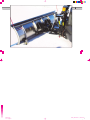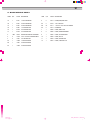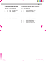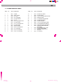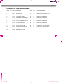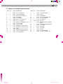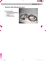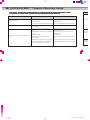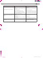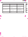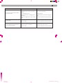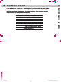
1
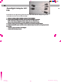
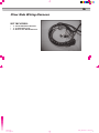
SNOW PLOWS
OPERATION & MAINTENANCE MANUAL
09/06
Manual.pub
tile 1 of page 1
Friday, November 17, 2006 12:29
Black
Magenta
Yellow
Cyan
INTRODUCTION
Congratulations on the purchase of your new AirAir-Flo®
Flo QuickQuick-Silver™
Silver
Snow Plow. AirAir-Flo®
Flo Manufacturing has produced this Operation and
Maintenance Manual to familiarize you with the distinct features we
have created for snow plowing safety and efficiency, and to help you
get the MAXIMUM PERFORMANCE from your AirAir-Flo®
Flo
QuickQuick-Silver™
Silver Snow Plow. By following the recommended operation
and maintenance instructions, your QuickQuick-Silver™
Silver Snow Plow will be
ready before the first snow and you will be an expert in
it ’ s operation.
Most vehicle manufacturers insist that vehicles which are to be used
for snow plow operations be equipped with distinct options and
accessories. Vehicles with AirAir-Flo®
Flo QuickQuick-Silver™
Silver Snow Plows
installed Must be equipped as to meet vehicle manufacturer ’ s
specifications and recommended options for snow plowing use. DO
NOT EQUIP ANY VEHICLE WITH A SNOW PLOW WITHOUT
CONSULTING VEHICLE MANUFACTURER
MANUFACTURER ’ S
RECOMMENDATIONS.
Air--Flo®
WARNING: Air bag deployment while using an Air
Flo snow plow is
not covered under AirAir-Flo®
Flo Manufacturing, Inc. Warranty.
TA
For optimum performance, AirAir-Flo®
Flo Manufacturing recommends that
vehicles used for snow plowing be equipped with the following
options:
•
4 Wheel Drive
•
Snow Plow Prep Package
•
Mud and Snow Tires
•
Increased Radiator Cooling
•
Transmission Cooler
•
Automatic Transmission
•
Power Steering
•
Power Brakes
•
Minimum 100 Amp Alternator
•
Minimum 600 C.C.A. Battery
Qu
Ve
Pa
Ge
Wir
Qu
Tro
Saf
Hy
Wa
No
AirAir-Flo Manufacturing reserves the right to change design
specifications and furnish products so altered without prior notice.
Air-Flo® Manufacturing Quick-Silver™ snow plow equipment should be used only on vehicles equipped with manufacturer ’ s snow plow
preparation packages. Plowing snow without the original snow plow preparation package may damage your vehicle or impair the operation and
control of the vehicle with the added weight of the equipment. Snow plowing with a vehicle not recommended by the manufacturer for that
purpose may void your new vehicle warranty. If your vehicle is not originally equipped with a snow plow preparation package, additional
equipment and options may be necessary before plowing. Owners should consult with their truck dealers before the purchase and installation of
this equipment. CAUTION: The installation, on any vehicle, of these parts is not a substitute for the original snow plow preparation package as
offered from the vehicle’ s manufacturer.
Manual.pub
tile 1 of page 2
The
Qu
Friday, November 17, 2006 12:29
Black
Magenta
Yellow
Cyan
•
•
•
TABLE OF CONTENTS
The QuickQuick-Silver™
Silver Snow Plow
Quick--Silver
Silver™ Models
Quick
2
4
QuickQuick-Silver™
Silver Operation
Vehicle Application Requirements
6
12
14
Parts Diagram and List
General Maintenance
Wiring
Quick--Stick
Stick™ Hand Held Control
Quick
1
Page
26
27
Trouble Shooting Guide
Safety
36
38
44
Hydraulic System
Warranty
46
47
Notes
48
PLEASE READ
AirAir-Flo Manufacturing requests that
you read this manual completely. It is
the consumers responsibility to be
completely aware of all important
operation and safety
recommendations.
ALWAYS INSIST ON GENUINE AIR-FLO PARTS & ASSESSORIES
•
Warranty Protection
•
Made Specific to AirAir-Flo®
Flo Specifications •
Better Performance
•
Always the Right Fit
Always Your Best Value
Manual.pub
tile 1 of page 3
•
•
Longer Wear
Friday, November 17, 2006 12:29
Black
Magenta
Yellow
Cyan
2
QUICK-SILVER™ SNOW PLOW
Please get to know your Quick-Silver™ Snow Plow. It is the consumers
responsibility for proper operation and maintenance.
MOLD BOARD
11 gauge 304 Stainless Steel or 11 gauge Carbon Steel
CUTTING EDGE
Produced with Hi Carbon Steel for an extended operating life.
Easily Replacable.
SKID SHOES
Adjustable and easily replacable that allow you to plow at the
proper height.
QUADRANT
Produced of high quality carbon steel. Allows mold board to
adjust to for plowing angles.
PIVOT PIN
Made of stainless steel. Attaches mold board to quadrant.
RIBS
Made of 1/4 ” 304 stainless or carbon steel. Help support the
mold board.
AA-FRAME
Attaches plow and quadrant to the light mount assembly.
LIGHT MOUNT ASSEMBLY
Houses light mounts, hydraulics, electrical components,
QuickQuick-Latch®
Latch assembly, height adjuster brackets and
mounting forks.
PLOW LIGHTS
Complies with all State and Federal Vehicle Safety Standards
with the AutoAuto-Light™
Light feature.
Manual.pub
tile 1 of page 4
ELECTRIC / HYDRAULIC POWER UNIT
Hydraulically adjusts mold board position. Raises, lowers, angles
left and right, holds and floats the moldboard.
QUICKQUICK-LATCH®
LATCH ASSEMBLY
Allows for mounting and dismounting from chassis in seconds.
LATCH TAB
Readies the cam latch handle for mounting.
QUICKQUICK-LATCH®
LATCH LOCKING CAMS
Spring loaded mechanism to automatically lock plow to chassis.
LATCH CAM HANDLES
Indicates that QuickQuick-Latch®
Latch is successfully locked. Also allows
for manual connection to chassis mount.
LOCK HANDLE
Single arm lever to allows for easy connection and
disconnection from the drivers side of the snow plow.
LIFT FRAME
Attachment for lift cylinder and dual chains to lift and lower
plow to proper position.
PIVOTING JACK STAND
Positions plow for easy mounting and dismounting from chassis.
WIRING HARNESS
Convenient single plug connection to power your plow.
CHASSIS MOUNTING BRACKET
Connects snow plow assembly to chassis frame.
Friday, November 17, 2006 12:29
Black
Magenta
Yellow
Cyan
3
Manual.pub
tile 1 of page 5
Friday, November 17, 2006 12:29
Black
Magenta
Yellow
Cyan
4
QUICK SILVER™ MODELS
Quick--Silver™ Snow Plow is available
The Quick
in 3 sizes with either Carbon Steel or
Stainless Steel Mold Boards. All of the
Quick-plows come with our exclusive Quick
Latch® Mounting System.
SP
MODEL
QSSQSS-75
QSCQSC-75
QSC--75 - 7 ’ 6 ” Carbon Steel Mold Board
QSC
QSS--75 - 7 ’ 6 ” Stainless Steel Mold Board
QSS
QSSQSS-80
QSCQSC-80
QSC--80 - 8 ’ Carbon Steel Mold Board
QSC
QSS--80 - 8 ’ Stainless Steel Mold Board
QSS
QSSQSS-85
QSCQSC-85
QSC--85 - 8 ’ 6 ” Carbon Steel Mold Board
QSC
QSS--85 - 8 ’ 6 ” Stainless Steel Mold Board
QSS
Manual.pub
tile 1 of page 6
Friday, November 17, 2006 12:29
Black
Magenta
Yellow
Cyan
SPECIFICATIONS
MODEL
BLADE
WIDTH
BLADE
HEIGHT
BLADE
GAUGE
TRIP
SPRINGS
VERTICAL
RIBS
SHOCK
ABSORBER
ANGLING
RAMS
PLOWING
WIDTH
APPROX.
WEIGHT
CUTTING
EDGE
QSSQSS-75 Stainless
7 1/2’
29”
11
4
7
1
1 1/2’ X 10”
6’ 6”
641
3/8” x 6”
QSCQSC-75
7 1/2’
29”
11
4
7
1
1 1/2’ x 10”
6’ 6”
641
3/8” x 6”
QSSQSS-80 Stainless
8’
29”
11
4
7
1
1 1/2’ x 10”
6’ 11”
657
3/8” x 6”
QSCQSC-80
8’
29”
11
4
7
1
1 1/2’ x 10”
6’ 11”
657
3/8” x 6”
QSSQSS-85 Stainless
8 1/2’
29”
11
4
7
1
1 1/2’ x 10”
7’ 4”
674
3/8” x 6”
QSCQSC-85
8 1/2’
29”
11
4
7
1
1 1/2’ x 10”
7’ 4”
674
3/8” x 6”
Manual.pub
tile 1 of page 7
BLADE
STEEL
5
Carbon
Carbon
Carbon
Friday, November 17, 2006 12:29
Black
Magenta
Yellow
Cyan
6
QUICK-SILVER™ OPERATION
Manual.pub
tile 1 of page 8
Friday, November 17, 2006 12:29
Black
Magenta
Yellow
Cyan
7
Manual.pub
tile 1 of page 9
Friday, November 17, 2006 12:29
Black
Magenta
Yellow
Cyan
8
QUICK-SILVER™ OPERATION
TO ATTACH PLOW
!Failure to follow installation and removal procedures may result in serious injury, death or damage to property.
1. Make sure jack stand is set at proper height (See initial Jack Settings) and hitch extensions are level. (#10)
2. Place latch cam handles in horizontal (down) position.
3. Pull up on latch tab to release handle. (#3)
4. Drive into plow until latch cams automatically engage the receiver rod. If plow attaches and latch cam handle moves fully
rearward (as in Diagram #9), go to step #5. If not, see #4a & #4b below
a) If hitch extensions will not partially engage, then jack stand can be raised or lowered to allow engagement.
b) If hitch extensions are only partially engaged, then plug in electrics and place plow in float by holding the down
control until float light is on. Once in float, check to see if jack stand needs to be raised or lowered and make necessary
necessary
adjustments. Then, repeat step #4
5. Place lock pin (#5) through lock handle and lock tabs after plow is attached.
6. Connect power harness. (#6)
7. Raise plow to full up position.
jack
k pin
8. Raise jack stand by pulling spring loaded jack pin while pulling up on the jack positioning handle. Release spring loaded jac
and allow jack to lock in the raised horizontal position.
Manual.pub
tile 1 of page 10
Friday, November 17, 2006 12:29
Black
Magenta
Yellow
Cyan
INIT
NO
the
1. F
N
2. A
3. T
4. C
d
9
INITIAL JACK STAND SETTINGS
NOTE: Truck receiver height and plow hitch extensions (#10)should be aligned level. Any variance can be eliminated with
the jack stand.
1. From a level surface, measure from the ground to any reference point on the plow mount attached to the truck.
Note measurement.
2. Attach the plow to the truck. Lower the jack stand, and then lower the plow.
3. Take the same measurement as in step 1. Note any difference in height.
4. Crank the jack stand up or down to restore truck chassis to original height noted in Step 1. Once the initial setting is
done on the jack stand, little or no adjustment is needed for future plow operations.
Manual.pub
tile 1 of page 11
Friday, November 17, 2006 12:29
Black
Magenta
Yellow
Cyan
10
12
QUICK SILVER™ OPERATION
TO REMOVE PLOW
!Failure to follow installation and removal procedures may result in serious injury, death or damage to property.
1. Raise plow to full up position with blade straight.
2. Lower jack stand by pulling spring loaded jack locking pin while pushing down on the jack positioning handle.
Release spring loaded pin and allow jack to lock in the lowered, vertical position.
3. Position plow blade on the ground with the “ float ” control off.
NOTE: It may be necessary to raise the plow slightly off the ground to deactivate the float control, and then
set the plow back on the ground. It is important that the plow lift chains remain taut.
4. Disconnect power plug harness. Install weather cap on “ t ruck ” side plug. Push plow side plug into frame holder
for protection.
5. Remove lock pin on lock handle (#5), pull handle forward until holding latch drops into place. Plow is ready to
dismount.
6. Using caution, slowly back truck away from plow, making sure no obstructions exist.
NOTE: Re
Manual.pub
tile 1 of page 12
Friday, November 17, 2006 12:29
Black
Magenta
Yellow
Cyan
11
13
instructions.
ructions.
NOTE: Read and understand all operating instructions prior to operating plow. Refer to owners manual for complete operating inst
Manual.pub
tile 1 of page 13
Friday, November 17, 2006 12:29
Black
Magenta
Yellow
Cyan
12
VEHICLE APPLICATION REQUIREMENTS
RECOMMENDATIONS ARE BASED ON THE FOLLOWING:
•
•
•
•
•
•
BA
The snow plow, when installed on the vehicle, must comply with the applicable Federal Motor Vehicle
Standards (FMVSS).
The snow plow, when installed on the vehicle, must comply with the vehicle manufacturers stated
gross vehicle and axle weight ratings & front and rear weight distribution ratio.
Note: Gross vehicle and axle weight ratings are found on the driver side door cornerpost of the
vehicle. Rear ballast may be required to comply with these requirements in some cases. Refer
to Ballast Requirements (pg. 13).
Representative vehicle equipped with snow plow, all options, and front seat occupants must not
exceed vehicle GVWR or GAWR.
Additional limitations and requirements may apply in some cases.
Air--Flo instructions and
Installation, modification, and additional accessories must comply with Air
recommendations. Loading the vehicle with additional cargo, other truck equipment, or installing
snow plow accessories decreases the available capacity.
The actual vehicle as configured must be weighed if there is any uncertainty to whether available
capacity exists.
Manual.pub
tile 1 of page 14
Friday, November 17, 2006 12:29
Black
Magenta
Yellow
Cyan
•
•
•
13
BALLAST REQUIREMENTS:
•
•
•
When qualifying vehicles for snow plow eligibility, ballast (additional weight) must be considered. To
remain in compliance with the axle ratios and settings as specified by the vehicle manufacturer, when
necessary, rear ballast must be used.
It is important if ballast is required, that it is secured properly behind the rear axle. Sand bags may be
used as a ballast but must be contained using a retainer.
Please refer to manufacturer or dealer specifications for recommended ballast requirements
Manual.pub
tile 1 of page 15
Friday, November 17, 2006 12:29
Black
Magenta
Yellow
Cyan
14
QUICK-SILVER™ PARTS DIAGRAM & LIST
A– BLADE SERVICE PARTS
B– QUADRANT SERVICE PARTS
C– A-FRAME SERVICE PARTS
Manual.pub
tile 1 of page 16
Friday, November 17, 2006 12:29
Black
Magenta
Yellow
Cyan
15
D– LOWER LIFT FRAME SERVICE PARTS
E– UPPER LIFT FRAME SERVICE PARTS
F– NON-RETAIL SERVICE PARTS
(NOT SHOWN)
Manual.pub
tile 1 of page 17
Friday, November 17, 2006 12:29
Black
Magenta
Yellow
Cyan
16
QUICK-SILVER™ PARTS DIAGRAM
A– BLADE SERVICE PARTS
A– B
ITEM#
1A
1B
1C
1D
1E
1F
2
3
4
5A
5B
5C
Manual.pub
tile 1 of page 18
Friday, November 17, 2006 12:29
Black
Magenta
Yellow
Cyan
17
A– BLADE SERVICE PARTS
ITEM#
QTY
PART # DESCRIPTION
ITEM
QTY
PART#
DESCRIPTION
1A
1
51001
7.5' SS PLOW BLADE
6
2
51014
PLOW (SKID) SHOE ASSY
1B
1
51003
8.0' SS PLOW BLADE
6A
2
01484
7/16" LYNCH PIN
1C
1
51005
8.5' SS PLOW BLADE
6B
52
01471
1 1/16" ID X 1 3/4" OD FLAT WASHER
1D
1
51000
7.5' C PLOW BLADE
6C
2
51013
PLOW SHOE
1E
1
51002
8.0' C PLOW BLADE
7
1
24000
LABEL, SERIAL TAG
1F
1
51004
8.5' C PLOW BLADE
8
2
24090
LABEL, DANGER/WARNING
2
1 SET
10025
PLOW GUIDE ASSY W/ FASTENERS
9
1
24095
LABEL, ATTACH/DETACH
3
8
01076
1/2" X 1 3/4" GR. 8 CARRIAGE BOLT
10
1
24092
LABEL, AIR FLO
4
8
01487
1/2" TOPLOCK NUT
11
1
24094
LABEL, QUICKSILVER
5A
1
51006
7.5' CUTTING EDGE
12
1
24091
LABEL, LARGE AIR-FLO
5B
1
51007
8.0' CUTTING EDGE
5C
1
51008
8.5' CUTTING EDGE
Manual.pub
tile 1 of page 19
Friday, November 17, 2006 12:29
Black
Magenta
Yellow
Cyan
18
4
QUICK-SILVER™
QUICK-SILVER™ PARTS
PARTS LIST
DIAGRAM
B- QUADRANT SERVICE PARTS
BITE
1
2
3
4
5
6
7
8
9
Manual.pub
tile 1 of page 20
Friday, November 17, 2006 12:29
Black
Magenta
Yellow
Cyan
19
5
B- QUADRANT SERVICE PARTS
F– NON RETAIL SERVICE PARTS (Not Shown)
ITEM#
QTY
PART # DESCRIPTION
QTY
PART # DESCRIPTION
1
4
01442
5/8" EYE BOLT ASSY
1
1
15064
BASE ASSEMBLY (18249)
2
4
10016
TRIP SPRING
2
1
15056
MOTOR DC, 12V - 4.5"
3
1
37052
SHOCK
3
1
15057
CARTRIDGE 4-W/2-P
4
1
51012
QUADRANT
4
1
15058
CARTRIDGE 2W/2P, NC
5
3
01478
5/8" X 3" HEX BOLT GR. 8
5
4
15065
CAP SCREW SS 1/4"-20 X 2 3/4"
6
3
01479
5/8" TOPLOCK NUT
6
1
15059
SUCTION FILTER
7
2
01476
3/4" X 3 1/4" HEX BOLT GR. 8
7
1
15060
PUMP KIT
8
1
01477
3/4" JAM NUT
8
2
15066
TUBE, RTN 1/8" NPT
9
1
01475
3/4" TOP LOCK NUT
9
1
15067
TUBE, SUCTION 3/8" NPT
10
1
15061
RESV, 6 DIA X 5.5
11
1
15062
RESV, BREATHER - 3/8 NPT
12
1
15063
CARTRIDGE, 3W/2P
13
3
15055
COIL 10VDC, 2 PIN
14
1
15068
PLUG, FLUSH 3/8" NPT
Manual.pub
tile 1 of page 21
Friday, November 17, 2006 12:29
Black
Magenta
Yellow
Cyan
20
QUICK-SILVER™ PARTS DIAGRAM
C– A-FRAME SERVICE PARTS
C– A
ITEM#
1
2
3
4
5
6
7
8
9
10
11
12
13
14
15
Manual.pub
tile 1 of page 22
Friday, November 17, 2006 12:29
Black
Magenta
Yellow
Cyan
21
C– A-FRAME SERVICE PARTS
ITEM#
QTY
PART # DESCRIPTION
ITEM#
QTY
PART#
DESCRIPTION
1
1
51001
A-FRAME
16
1
51031
S/S JACK ADJ. HANDLE
2
2
01426
CHAIN - 30 LINKS
17
1
51032
S/S JACK HANDLE
3
2
01010
3/8" U-BOLT
18
1
09035
7/16" X 3 1/4" SILVER HANDLE COVER
4
2
01018
3/8" FLAT WASHER
19
1
51025
SCREW JACK FOOT
5
2
01016
3/8" LOCK WASHER
20
1
01508
3/4" INTERNAL RETAINING RING
6
2
01270
3/8" NUT
21
1
10028
JACK RELEASE SPRING
7
1
01480
3/4" X 4" FLANGE BOLT GR.8
22
1
51033
S/S JACK LOCK PIN
8
1
01475
3/4" TOPLOCK NUT
23
1
09038
7/16" X 2" SILVER HANDLE COVER
9
2
01011
3/4" X 3 1/2" HEX BOLT GR.8
24
1
51026
LEFT HAND SCREW JACK MOUNT
10
2
01475
3/4" TOPLOCK NUT
25
1
51027
RIGHT HAND SCREW JACK MOUNT
11
2
37051
ANGLE CYLINDER
26
1
51028
12
2
01189
5/32" X 3 1/2" COTTER PIN
13
2
01036
3/4" FLAT WASHER
27
1
01029
14
2
01482
3/4" X 3 1/2" CLEVIS PIN
28
1
01486
15
2
01472
5/16" X 1 1/2" LYNCH PIN
29
2
01034
SCREW JACK EXTENTION TUBE
(NOT SHOWN)
3/8" X 2" HEX BOLT GR. 8 - TUBE
EXTENSION (NOT SHOWN)
3/8" X 2 3/4" HEX BOLT GR. 8 JACK FOOT
3/8" LOCK NUT
Manual.pub
tile 1 of page 23
Friday, November 17, 2006 12:29
Black
Magenta
Yellow
Cyan
22
QUICK-SILVER™ PARTS DIAGRAM
D– LOWER LIFT FRAME SERVICE PARTS
D–
ITE
1
2
3
4
5
6
7
8
9
10
11
12
Manual.pub
tile 1 of page 24
Friday, November 17, 2006 12:29
Black
Magenta
Yellow
Cyan
23
D– LOWER LIFT FRAME SERVICE PARTS
ITEM#
QTY
PART # DESCRIPTION
ITEM#
QTY
PART# DESCRIPTION
1
1
09037
RED VINYL GRIP
13
1
01500
3/8" X 3/4" HEX BOLT GR. 8
2
1
01430
DETENTION PIN W/ LANYARD
14
1
01047
3/8" LOCK WASHER
3
1
51023
LOCK HANDLE CATCH
15
1
01420
3/8" FLAT WASHER
4
1
51022
CAM BLOCK W/ CROSS SHAFT
16
1
01049
1/2" FLAT WASHER
(ASSEMBLED)
17
1
01188
1/8" X 1" COTTER PIN
5
2
01428
7/9"-9 X 4 3/4" HEX BOLT GR. 8
18
1
01420
3/8" FLAT WASHER
6
2
01491
7/8" FLAT WASHER
19
1
01188
1/8" X 1" COTTER PIN
7
2
01492
7/8" CENTERLOCK NUT
20
4
01420
3/8" FLAT WASHER
8
1
51021
LEFT HAND CAM ASSIST HANDLE
21
1
01496
3/4" X 3" CLEVIS PIN
9
4
01019
5/16" X 2" ROLL PIN - SS
22
1
01189
5/32" X 1 1/2" COTTER PIN
10
4
51015
TRUCK HITCH ROLLERS - SS
23
4
01012
5/8" X 2" HEX BOLT GR.8
11
1
51020
RIGHT HAND CAM ASSIST HANDLE 24
4
01479
5/8" TOPLOCK NUT
12
2
09036
SILVER HANDLE COVER
Manual.pub
tile 1 of page 25
Friday, November 17, 2006 12:29
Black
Magenta
Yellow
Cyan
24
QUICK-SILVER™ PARTS DIAGRAM
E– UPPER LIFT FRAME SERVICE PARTS
E–
ITE
1
2
3
4
5
6
7
8A
8
9
10
11
12
13
14
15
Manual.pub
tile 1 of page 26
Friday, November 17, 2006 12:29
Black
Magenta
Yellow
Cyan
25
E– UPPER LIFT FRAME SERVICE PARTS
ITEM#
QTY
PART # DESCRIPTION
ITEM#
QTY
PART# DESCRIPTION
1
2
01496
3/4" x 3" CLEVIS PIN
16
2
01042
1/4" LOCK WASHER
2
2
01037
3/4" NYLON WASHER
17
2
01305
1/4" NUT
3
2
01189
5/32" X 1 1/2" COTTER PIN
18
1
51024
PUMP MOUNT
4
1
51010
LIFT FRAME
19
2
01015
1/2" x 3 1/4" HEX BOLT GR.8
5
1
37050
LIFT CYLINDER
20
2
01049
1/2" FLAT WASHER
6
2
01189
5/32" X 1 1/2" COTTER PIN
21
2
01337
1/2" LOCK NUT
7
2
01496
3/4" x 3" CLEVIS PIN
22
1 SET
07180
LIGHT KIT
8A
1
13040
HOSE KIT - INCLUDES 8,9,10, & 11
23
1
07200
8
1
13042
1/4" X 24" HOSE
STORAGE PLUG W/ CARRIAGE
BOLTS
9
2
13041
1/4" X 41" HOSE
24
1
07182
PLOW SIDE WIRING HARNESS
10
1
13043
#6 MORB X 1/4" MALE JIC 90°
25
1
07188
1 1/8" CLAMP
11
5
13044
#6 MORB X 1/4" FEMALE JIC 90°
26
1
07187
1/2" CLAMP
12
1
15054
PUMP
13
1
01430
DETENTION PIN W/ LANYARD
14
2
01509
1/4" X 2 1/4" HEX BOLT GR. 8
15
8
01329
1/4" FLAT WASHER
Manual.pub
tile 1 of page 27
27
2
07187
1/2" CLAMP
28
2
01305
1/4" NUT
29
2
01042
1/4" LOCK WASHER
30
2
01328
1/4"-20 X 1" HEX BOLT GR. 8
Friday, November 17, 2006 12:29
Black
Magenta
Yellow
Cyan
26
QUICK-SILVER™ GENERAL MAINTENANCE
V
! To reduce friction and wear between moving parts, inspect the
overall condition of the complete snow plow on a regular basis.
•
•
•
•
•
•
•
Lubricate all shafts, pivots, and cam lock hitches with low temperature grease.
To ensure proper connection and conductivity, clean plow harness ends with brake cleaner, coat
contacts with white lithium or dielectric grease and place weather caps on both plowplow-side and
trucktruck-side when not in use. AirAir-Flo Manufacturing recommends this procedure be completed on the
snow plow harness, both plowplow-side and trucktruck-side plugs, every 25 hours. All other connections need
to be serviced every 100 hours.
Hydraulic hoses, hose ends, connectors, cylinders, and wiring connectors need to be inspected
periodically. Any excessive wear or damage requires replacement of all affected components.
Before the start of each plowing season, it is recommended to change pump fluid using a Dexron
automatic transmission fluid. Also installation of the plow and activation of the pump at least once
during the unused months is recommended.
To avoid rust or corrosion, any paint chips on the plow frame should be touched up with black paint.
Check all hardware, including nuts, bolts, pins, springs, and spring hardware, making sure they are
tight and in good condition. Replace any damaged, worn, or broken hardware or components
immediately.
Check pump reservoir regularly for proper fluid level. Fluid level should be approximately 1/2” b elow
bottom of filler neck. DO NOT OVERFILL.
Manual.pub
tile 1 of page 28
Friday, November 17, 2006 12:29
Black
Magenta
Yellow
Cyan
P
K
•
•
•
•
•
•
WIRING
27
Vehicle Side Wiring Harness
P/N 07184
KIT INCLUDES:
•
•
•
•
•
•
131311-
Manual.pub
tile 1 of page 29
Vehicle Side Wire Harness
Blue Splice Lock Connectors
V.S Weather Cap
Relays
Relay Plug Chart
V.S Mount Bracket
Friday, November 17, 2006 12:29
Black
Magenta
Yellow
Cyan
28
Headlight Adapter Kit
Ve
P/N
Installation & Operating Instructions for Advanced Adapter System
ADAPTER INSTALLATION PROCEDURE:
1. Remove existing vehicle headlight connector from headlight.
2. Plug in (ASS) headlight connector into the vehicle headlight receptacle.
Note: If more than one plug is present, match color of connectors; i.e.
Gray to Gray, Black to Black. In Chevy daylight running: Clear to Gray.
3. Plug the existing vehicle headlight connector into the (ASS) headlight adaptor.
4. Plug in the Black five pin connector into the White five pin connector on the (ASS) harness.
Final Steps:
• Check for proper operation of headlights.
• Check that all wiring is secure.
Manual.pub
tile 1 of page 30
Friday, November 17, 2006 12:29
Black
Magenta
Yellow
Cyan
29
Vehicle Side Wiring Harness—MAIN PLUG
Manual.pub
tile 1 of page 31
Friday, November 17, 2006 12:29
Black
Magenta
Yellow
Cyan
30
Vehicle Side Wiring Harness - LIGHTING HARNESS
Manual.pub
tile 1 of page 32
Ve
Friday, November 17, 2006 12:29
Black
Magenta
Yellow
Cyan
31
Vehicle Side Wiring Harness - CONTROL HARNESS
Manual.pub
tile 1 of page 33
Friday, November 17, 2006 12:29
Black
Magenta
Yellow
Cyan
32
P
Vehicle Side Wiring Harness - RELAYS
P
PLUGGING CHART FOR RELAYS
K
PIN#
85
86
30
87
87a
Manual.pub
tile 1 of page 34
RELAY # 1
RELAY # 2
RELAY # 3
HIGH
LOW
GROUND
COLOR
GREEN/YELLOW
WHITE/BLACK
YELLOW
YELLOW/BLACK
YELLOW/RED
AWG
18
18
16
16
16
PIN #
85
86
30
87
87a
COLOR
GREEN/YELLOW
WHITE/BLACK
GREEN
GREEN/BLACK
GREEN/RED
AWG
18
18
16
16
16
PIN #
85
86
30
87
87a
COLOR
GREEN/YELLOW
WHITE/BLACK
WHITE/RED
WHITE
N/A
•
•
•
AWG
18
18
16
16
18
Friday, November 17, 2006 12:29
Black
Magenta
Yellow
Cyan
33
Plow Side Wiring Harness
P/N 07182
KIT INCLUDES:
•
•
•
1- Plow Side Wire Harness.
1- P.S Weather Cap.
3– Screws for DIN Connector
Manual.pub
tile 1 of page 35
Friday, November 17, 2006 12:29
Black
Magenta
Yellow
Cyan
34
Plow Side Wiring Harness - MAIN PLUG
Manual.pub
tile 1 of page 36
Pl
Friday, November 17, 2006 12:29
Black
Magenta
Yellow
Cyan
35
Plow Side Wiring Harness - LIGHTING HARNESS
Manual.pub
tile 1 of page 37
Friday, November 17, 2006 12:29
Black
Magenta
Yellow
Cyan
36
QUICK-STICK™ Hand Held Control
HANDHELD CONTROL
1. Depending on how the truck side plow harness is wired, the QuickQuick-Stick may operate with the ignition
switch in the ON or OFF position. Please consult with your installer.
2. Turn the ON/OFF switch on the control to the ON position. The control keypad will glow green, indicating the control is on. NOTE: THE ON/OFF SWITCH CAN BE USED AS AN EMERGENCY STOP
WHEN REQUIRED.
SO
Th
an
3. To control the plow, press the corresponding buttons on the keypad.
4. To engage the FLOAT Mode, press the down button for 1.3 seconds. The FLOAT indicator light, located in the center of the keypad (logo), will change from green to red. To cancel the FLOAT mode,
momentarily press the UP button. FLOAT mode will automatically cancel after 17 minutes and the
FLOAT indicator light will turn back to green. To restart FLOAT mode, repeat step 4.
BLADE OPERATION TIME OUTS
All control functions automatically time out (shut off) after a period of time. This helps reduce wear on the
pump motor and prevent unnecessary battery drain. The UP function will time out after 2.6 seconds,
while the LEFT and RIGHT functions will time out after 3.0 seconds.
AUTOMATIC SHUTDOWN
After being idle for approximately 22 minutes, the control will automatically turn off and the indicator light
located at the center of the keypad (logo) will blink from red to green. To restart the control, turn the control OFF (ON/OF switch) and then back ON.
Manual.pub
tile 1 of page 38
Friday, November 17, 2006 12:29
Black
Magenta
Yellow
Cyan
(L
37
SOFT STOP
The Control automatically allows the blade to coast to a soft stop, This results in a smoother operation
and decreased wear on the plows hydraulic system.
ON/OFF SWITCH
(Located on the Top of the Handheld control)
KEY PAD
! WARNING
TO PREVENT ACCIDENTAL ACTIVATION OF PLOW, TURN PLOW
OFF WHEN NOT IN USE
Manual.pub
tile 1 of page 39
Friday, November 17, 2006 12:29
Black
Magenta
Yellow
Cyan
38
QUICK-SILVER™ Trouble Shooting Guide
This guide is provided as a general reference to possible plow failures. Please remember to contact
your local AirAir-Flo Quick Silver™ Dealer for factory original parts and trained service.
CONDITION
Motor does not run.
Motor will not shut off.
Snowplow will not raise or raises slowly or partially.
Manual.pub
tile 1 of page 40
POSSIBLE CAUSE
CORRECTION
1) Snow plow harness not connected.
1) Properly connect all wire harnesses.
2) Fuses are blown.
2) Replace fuses.
3) Cab control malfunction or fault in wiring.
3) See an Air-Flo dealer for repair information.
Motor relay or cab control malfunction or
fault in wiring.
See an Air-Flo dealer for repair information.
1) Excesses weight on the blade and Aframe.
1) Remove built up snow and ice or any after
market accessories
2) Hydraulic Fluid level low or incorrect fluid
is used.
2) Fill reservoir to proper level with recommended fluid.
3) Fuses are blown.
3) Replace fuse.
4) Truck battery weak or malfunction in
charging system.
4) Replace battery and/or check charging system.
5) Motor worn or damaged or fault in wiring.
5) See an Air-Flo dealer for repair information.
6) Pump filter clogged, worn or damaged
pump, or hydraulic system malfunction.
6) See an Air-Flo dealer for repair information.
Snowplo
Snowplo
not float
Snowplo
raised po
Friday, November 17, 2006 12:29
Black
Magenta
Yellow
Cyan
39
CONDITION
Snowplow angles move slowly or partially.
Snowplow will not lower, lowers slowly, or will
not float.
POSSIBLE CAUSE
1) Hydraulic fluid level low or incorrect fluid is
used.
1) Fill reservoir to proper level with recommended fluid.
2) Vehicle battery weak or malfunction is charging system.
2) Replace battery and/or check charging system.
3) Air in angle cylinders.
3) Cycle plow to remove air.
4) Angle cylinders damaged or leaking.
4) See an Air-Flo dealer for repair information.
5) Motor worn or damaged or fault in wiring.
5) See an Air-Flo dealer for repair information.
6) Pump filter clogged, worn or damaged pump,
or hydraulic system malfunction.
6) See an Air-Flo dealer for repair information.
1) Hydraulic fluid is incorrect for outside temperature.
1) Use recommended fluid.
2) Quill adjusted in too far.
2) Adjust Quill out.
3) Blown fuse.
3) Replace fuse.
4) Cab control or hydraulic system malfunction
or fault in wiring.
4) See Air-Flo dealer for repair information
1) Hydraulic fittings or hoses loose or damaged.
1) Tighten or replace components or see an
Air-Flo dealer for repair information
Snowplow lowers by itself or will not stay in the
2) Cab control or hydraulic system malfunction.
raised position.
Manual.pub
tile 1 of page 41
CORRECTION
2) See an Air-Flo dealer for repair information.
Friday, November 17, 2006 12:29
Black
Magenta
Yellow
Cyan
40
CONDITION
Snowplow does not perform the selected
function or performs a different function.
Fluid Leaks from the hydraulic power unit.
Fluid leaks from angle or lift arms.
Cab control fuses blown.
Manual.pub
tile 1 of page 42
POSSIBLE CAUSE
CORRECTION
1) Hydraulic hose routing is incorrect.
1) See an Air-Flo dealer for repair information.
2) Cab control or hydraulic system malfunction.
2) See an Air-Flo dealer for repair information.
1) Reservoir overfilled.
1) Drain excess fluid and verify proper fluid
level.
Excessiv
while usi
2) Loose or damaged hydraulic fittings, hoses, 2) Tighten loose components or see an Air-Flo
dealer for repair information.
plugs, or hardware.
1) Angle or lift ram gland nut loose.
1) Tighten ram gland nut or see an Air-Flo
dealer for repair information.
2) Hydraulic fittings or hoses loose or damaged.
3) Angle or lift rams damaged.
2) Tighten or replace components, or see an
Air-Flo dealer for repair information.
1) Motor relay or cab control malfunction, or
fault in wiring.
1) See an Air-Flo dealer for repair information.
3) See an Air-Flo dealer for repair information.
Vehicle b
is not be
Snow plo
not at all
Friday, November 17, 2006 12:29
Black
Magenta
Yellow
Cyan
41
CONDITION
Excessive load on vehicle electrical system
while using snow plow.
POSSIBLE CAUSE
CORRECTION
1) Too many accessories on.
1) Turn off unnecessary accessories.
2) Hydraulic fluid not correct for outside temperature.
2) Use recommended fluid.
3) Quill adjusted in too far.
3) Adjust Quill out.
4) Vehicle battery weak or charging system
Malfunction.
4) Replace battery and/or check charging system.
5) Worn or damaged motor or pump, or fault in 5) See an Air-Flo dealer for repair information.
wiring.
Vehicle battery loses charge when snow plow
is not being used.
Snow plow headlamps operate irregularly or
not at all (snow plow attached).
Manual.pub
tile 1 of page 43
1) Vehicle battery weak.
1) Replace battery.
2) Fault in wiring.
2) See an Air-Flo dealer for repair information.
1) Snow plow wire harness not connected.
1) Properly connect wire harness.
2) Burned out bulbs or vehicle fuse.
2) Replace bulbs, clean contacts.
3) Fault in wiring.
3) See an Air-Flo dealer for repair information.
Friday, November 17, 2006 12:29
Black
Magenta
Yellow
Cyan
42
CONDITION
POSSIBLE CAUSE
N
CORRECTION
1) Burned out bulbs or vehicle fuse.
Vehicle headlamps operate irregularly or not at 3) Fault in wiring.
all (snow plow removed).
1) Replace bulbs or fuse.
Snow plow park / turn lamps not operating.
1) Burned out bulb or vehicle fuse.
1) Replace bulbs or fuse.
2) Fault in wiring.
2) See an Air-Flo dealer for repair information.
Manual.pub
tile 1 of page 44
3) See an Air-Flo dealer for repair information.
Friday, November 17, 2006 12:29
Black
Magenta
Yellow
Cyan
43
Notes
Manual.pub
tile 1 of page 45
Friday, November 17, 2006 12:29
Black
Magenta
Yellow
Cyan
44
SAFETY
SAFETY PRECAUTIONS
Fo
!CAUTION: Read owners manual prior to operation of plow.
!WARNING: To avoid serious injury: Lower blade when vehicle is parked. Be aware of temperature
changes which can change hydraulic pressure. In turn, this can cause blade to drop unexpectedly. This
may also cause damage to hydraulic components.
!WARNING: Including vehicle, blade and ballast: Do Not Exceed GVWR or GAWR. The vehicle rating
label is found on the drivers side vehicle door corner post.
!WARNING: Before placing vehicle on hoist, remove blade assembly.
!CAUTION: Plowing speed should not exceed 10 mph and transport speed should not exceed 45
mph. Speed should be reduced under adverse conditions.
•
•
•
Batteries produce explosive gases which can cause personal injury. Disconnect the battery before
removing or replacing any electrical connections. Always use and wear protective equipment when
working around batteries.
While operating snow plow, the airborne noise emmissions should be below 70db.
Wear safety goggles to protect your eyes from gasoline, battery acid and other foreign matter.
Manual.pub
tile 1 of page 46
•
•
•
•
For Your Personal Protection
•
•
Friday, November 17, 2006 12:29
Black
Magenta
Yellow
Cyan
45
For Your Personal Protection
•
Avoid touching hot surfaces such as exhaust pipes, hoses, engine and radiator.
•
Always have a BC rated fire extinguisher available for flammable liquid and electrical fires.
•
Gasoline is highly flammable and gasoline vapor is explosive. Keep all open flames away from gasoline tanks and lines. Clean up any spilled gasoline immediately.
•
Be aware that vehicle exhaust contains deadly carbon monoxide gas. Vent exhaust to the outside if
operating vehicle in an enclosed area.
•
Always inspect hydraulic hoses and components before using snow plow. Replace damaged or worn
parts immediately.
•
Do not use your hand to detect a hydraulic fluid leak as hydraulic fluid under pressure can cause skin
infection injury. Use a piece of cardboard or wood to detect possible leaks.
Manual.pub
tile 1 of page 47
Friday, November 17, 2006 12:29
Black
Magenta
Yellow
Cyan
46
HYDRAULIC SYSTEM
Q
Air--Flo Manufacturing’ s Quick
Quick--Flo ® hydraulic system provides a simple and reliable system
Air
for trouble free service. This efficient hydraulic system allows for smooth and fast plow
operations with minimal amperage draw. For hydraulic fluid type, filling instructions and fluid
change intervals, see General Maintenance Section.
System Capacity / Pump Motor Specifications
Thi
Ma
opi
the
the
ser
System Capacity - Reservoir: 1.5 qts.
12 Volt DC with +/- Connections
1500 PSI Pump Relief Valve
Ma
or p
2000 PSI Angling Relief Valve
4 1/2“ Diameter 1000 kw Motor
Gal/Rev Pump:
THI
IMP
and
of a
on
2.75 GPM @ 0 PSI 2 GPM @ 500 PSI
1.5 GP @ 1000 PSI 1.3 GPM @ 1500 PSI
Hydraulic Hose SAE 1/4”
Manual.pub
tile 1 of page 48
AIR
Plo
of T
one
sat
doe
par
Friday, November 17, 2006 12:29
Black
Magenta
Yellow
Cyan
QUICK-SILVER™ Snow Plow WARRANTY
47
AIRQuick--Silver™ Snow
AIR-FLO MANUFACTURING CO., INC., hereinafter referred to as “ Manufacturer ” , warrants each new Quick
Plow sold by the manufacturer to be free from defects in material and workmanship, under normal use and service, for a period
of Two (2)years after the date of delivery to the original retail purchaser, and Manufacturer will, at its option, replace or repair, at
one of the Manufacturer ’ s Dealer ’ s,
s , or at a point designated by the Manufacturer, any part or parts which shall appear to the
satisfaction of the Manufacturer upon inspection at such point, to have been defective in material or workmanship. This warranty
does not obligate the Manufacturer to bear any transportation charges in connection with the replacement or repair of defective
parts.
This warranty shall not apply to any Unit which shall have been installed or operated in a manner not recommended by the
Manufacturer, nor any Unit which shall have been repaired, altered, neglected or used in any way which, in the Manufacturer ’ s
opinion, adversely affects it ’ s performance; nor to any Unit in which parts not manufactured by the Manufacturer, or supplied by
the Manufacturer or by one of Manufacturer’
Manufacturer’ s Distributors or Service Centers, have been used; nor any accessories installed on
the unit where the accessory manufacturer has its own warranty; nor to normal maintenance services or replacement of normal
service items. Items this would pertain to include the Electric/Hydraulic Pump Assembly and Hydraulic Cylinders.
Manufacturer reserves the right to modify, alter, and improve a Unit or parts without incurring any obligation to replace any Unit
Unit
or parts previously sold with such modified, altered, or improved Unit or part.
THIS WARRANTY, AND THE MANUFACTURER ’ S OBLIGATION HEREUNDER, IS IN LIEU OF ALL OTHER WARRANTIES, EXPRESS,
IMPLIED, OR STATUTORY, INCLUDING ANY WARRANTIES OR MERCHANTABILITY OR OF FITNESS FOR A PARTICULAR PURPOSE,
and all other obligations or liabilities, including special or consequential damages or contingent liabilities arising out of the fa
failure
ilure
of any Unit or part to operate properly. No person is authorized to give any other warranty or to assume any additional obligation
obligation
on the Manufacturer ’ s behalf unless made in writing and signed by the Manufacturer.
AirAir-Flo Mfg. Co., Inc.
Prattsburgh, New York 14873
Manual.pub
tile 1 of page 49
Friday, November 17, 2006 12:29
Black
Magenta
Yellow
Cyan
48
NOTES
IMP
wil
Dat
Ser
Dea
Dea
Tele
Tel
Veh
Veh
Veh
Veh
Bla
Manual.pub
tile 1 of page 50
Friday, November 17, 2006 12:29
Black
Magenta
Yellow
Cyan
IMPORTANT: Please fill out completely and retain for your records. This information
will be necessary to process any warranty claims.
Date of Purchase:
Serial Number:
Dealer:
Dealer Contact:
Telephone:
Vehicle Mount Kit:
Vehicle Make:
Vehicle Model:
Vehicle Year:
Blade Size:
Manual.pub
tile 1 of page 51
□ 7 1/2’
□ 8’
□ 8 1/2 ’
Friday, November 17, 2006 12:29
Black
Magenta
Yellow
Cyan
AirAir-Flo Manufacturing
40 South Main Street
Prattsburgh, NY 14873
Manual.pub
tile 1 of page 52
Friday, November 17, 2006 12:29
Black
Magenta
Yellow
Cyan