1
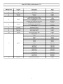
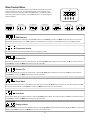
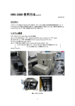
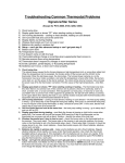
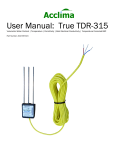
Check that the unit has not been damaged during transport
Protection Against Fire
1.
2.
3.
4.
5.
Maintain a minimum of 1 foot distance from any type of flame.
Replace fuse only with the specified type and rating.
Do Not install the unit to close to a heat source.
Make sure cable are properly secured away from unit movement.
Maximum surface operating temperature 80º.
Protection Against Fire
1.
2.
3.
4.
Disconnect power before servicing.
For connection to main power supply proceed to page 4.
This unit must be earthed. (electronically grounded)
Do not expose unit to rain or moisture.
Protection Against Mechanical Hazards
1. Make sure head movement is not blocked.
2. Use safety chain when hanging unit
3. Unit surface may reach high temperature. Allow about 5 minutes after lamp has been turned off before moving.
3
Technical Features
Part Numbers
Fixture
Flight Case
1100 - AXIS LED
P-1100DUALCASE
Mechanical Specifications
7”
9.25”
Pan: 360° Tilt: 270°
DMX Connectors:
3-pin XLR connectors
Thermal:
Maximum ambient temperature 35° C
Maximum surface temperature 80° C
Mounting Points:
2 pairs of L-turn locks
Fastening System:
2 quick clamp release
3.5”
9.5”
10.75”
Packaged for Shipping
Fixture
4.75”
Size: 12.25”L x 13.5”W x 14.25”H
Size: 16.5”L x 16.5”W x 19”H
Weight: 24 lbs
Weight: 28 lbs
12.25
Electrical Specifications
LED Quantity:
Red:
Green:
Blue:
54
18
18
18
LED Watts: 3
LED Lifetime: 60,000 - 100,000 hours
LED Angle: 32°
Power Consumption: 110V 50/60 Hz
Ballast: Electronic
Watts: 236
Amps: 2.50
Control & Programming
Protocol: DMX 512
DMX Channels: 12 Channels
Pan, Tilt, Pan Fine, Tilt Fine, Speed, Control, Red, Green, Blue, Strobe, Macro, Dimmer
4
13.5”
Main Power Connection
Caution!
1.
2.
3.
Do not connect fixture to a dimmer system.
This unit must be earthed. (electronically grounded)
Replace fuse only with the specified type and rating.
The occupation of the connection-cable is as follows:
110V 50/60hz Connection
Cable (USA)
Cable (EU)
Pin
International
Brown
Brown
Live
L
Light Blue
Light Blue
Neutral
N
Yellow/Green
Yellow/Green
Pin
DMX-512 Connection
The fixture is equipped with 3 pin XLR Sockets for DMX input and output. The sockets are wired in parallel. Only use a shielded
twisted pair cable designed for RS-485 and 3 pin XLR plugs and connectors in order to connect the controller with the fixture or
the fixture with another.
DMX—output
DMX—input
2
1
1. Shield/Ground
1
2
2. Signal (-)
3
3. Signal (+)
3
Caution!
At the last fixture the DMX signal needs to be terminated with a terminator. Solder a 120
Ohm resistor between the (-) and the (+) signal into a 3 pin XLR plug and plug it in to the
last fixture on the signal run. Pre-manufactured terminator plugs are available for
purchase from your Mega-Lite dealer (HOS-DMXT).
Note: After switching the unit on it will automatically detect whether DMX 512 data is received or not . There is a single red LED
above the display that will flash once it is receiving DMX. If there is no DMX present the LED will not light.
5
Rigging the fixture
Caution!
1.
2.
3.
4.
The installations must be carried out by an authorized dealer or trained professional.
Unit may cause severe injures if you have doubts concerning the safety do not install.
Unit is to be 24inches away from flammable materials (decoration material)
Use high quality installation equipment to hang unit.
When rigging a unit it is very important that you follow common safety procedures. Rigging requires extensive experience including but not limited to calculating working loads, material being used and periodic safety inspections. If you lack these qualifications, do not attempt the installation yourself, instead use a professional structural rigger.
When rigging the unit always be secured with a secondary safety attachment. The installation location of the projector has got to
be built in the way that it can hold 10 times the weight for 1 hour with out any harming. Installation should be checked at least
one time a year by a skilled person.
6
Axis LED DMX profile-version 1.0
DMX Channel
Function
Description
Value
1
2
3
4
Pan
Tilt
Pan Fine
Tilt Fine
5
Speed
6
Control
0-255
0-255
0-255
0-255
0
1-244
245-252
253-255
0-127
140-150
151-255
0-255
7
Red LED
Pan course
Tilt course
Pan fine
Tilt fine
Max speed (tracking mode)
Max to min speed (vector mode)
Changes
Changes with pan and tilt movement
Fan speed from fast to slow
Reset (hold for 3 secounds)
No Changes
Red LED (0-100%)
8
Green LED
Green LED (0-100%)
0-255
9
Blue LED
Blue LED (0-100%)
0-255
10
Strobe
Strobe from slow to Fast
0-255
No Function
0
Red
Green
Blue
Yellow
Purple
Aqua
Fast Scroll
Red Pulse
Green Pulse
Blue Pulse
Yellow Pulse
Purple Pulse
Aqua Pulse
White Pulse
Dimmer from off to full
1-19
20-39
40-59
60-79
80-99
100-119
120-139
140-159
160-179
180-199
200-209
210-219
220-229
230-255
0-255
11
Macro
12
Dimmer
7
Main Control Menu
The control board on the fixture base is your interface to access and control
all the functions on the unit. Its digital display gives you a code view of the
options and functions including errors and diagnostics. The following will explain each function and its options. Press Mode button to scroll through the
different options.
MODE
ENTER
0-512
UP
Programme
DOWN
DMX Address
DMX
MODE
ENTER
UP
DOWN
Pan Reverse
Tilt Reverse
Demo Mode
Unit Reset
Display
Yes/No
Yes/No
Yes/No
Yes/No
Yes/No
DMX Address
Use the up/down keys to select the required DMX channel. Press Enter to confirm or Mode to exit and return to main menu.
The display will flash if there is no DMX signal been received from the console. The Axis 500 uses 16 or 14 DMX channels
Programme Version
No function this will just show you what version of program you have.
Reverse Pan
This function allows you to invert the Pan direction. Use the up/down keys to select, Y to invert pan and N not to invert the pan.
Press Enter to confirm or Mode exit and return to the mail menu.
Reverse Tilt
This function allows you to invert the Tilt direction. Use the up/down keys to select, Y to invert tilt and N not to invert the tilt.
Press Enter to confirm or Mode exit and return to the mail menu.
Demo Mode
This function allows you to turn on the demo mode operation. Use the up/down keys to select, Y to turn demo mode on and N
not to turn demo mode on. Press Enter to confirm or Mode exit and return to the mail menu.
Unit Reset
This function allows you to reset the fixture. Use the up/down keys to select, Y to reset the fixture and N not to reset the fixture.
Press Enter to confirm or Mode exit and return to the mail menu.
Display reverse
This function allows you to invert the display direction. Use the up/down keys to select, Y to invert display and N not to invert the
display. Press Enter to confirm or Mode exit and return to the mail menu.
8
Cleaning and maintenance
Installation Maintenance: The operator has to make sure that the unit is operating safely and has the installations and electronics checked by an expert every 2 years.
The following points have to be considered during the inspection:
1) All screws used for installing the device or part of the device have to be tightly connected and must not be corroded.
2) There must not be any deformations on the housing, fixation and installation spots (ceiling, suspension, trussing).
3) Mechanically moved parts like axles, fans and other must not show any traces of wearing and must not rotate with unbalances.
4) The electronic power supply cables must not show any damages, material fatigue (e.g. porous cables) or sediments. Further
instructions depending on the installation spot and usage have to be adhered by a skilled installer and any safety problems
have to be removed.
Disconnect from mains before starting maintenance operation!
Caution Danger to life!
We recommend a frequent cleaning of the device. Please use a moist, lint free cloth. Never use alcohol or solvents!
1) The objective lens will require periodic cleaning on usage and environment. Environment with foggers will require more periodic cleaning as fog fluid tends to build up residues, reducing the light output.
2) The cooling-fans should be cleaned monthly. DO NOT blow high pressure air into fans as incorrect rotation can damage the
fans operation.
3) The gobos, dichroic color filters and internal lenses may be cleaned with soft brush using soapy water.
Note: There is no serviceable parts inside the device except for the fans and the fuse. Maintenance and service operations are
to be carried out by authorized dealers.
Replacing the fuse: Only replace the fuse with the same type and rating.
Replacing the power cable: If the power cable of this device becomes damaged, it has to be replaced by authorized dealers only
In order to avoid hazards.
Should you have further questions , please contact your dealer.
Parts List
P-1100C
Quick Release Mount Set
P-1100PBS
Plastic Body Set
P-1100DISC
Display Card
P-1100PM
Pan Motor
P-1100DMXC
DMX Card
P-1100PS
Power Switch
P-1100FH
Fuse Holder
P-1100PSUP
Power Supply
P-1100LEDb
Blue LED
P-1100RF
LED Reflector
P-1100LEDg
Green LED
P-1100SF
Small Fan
P-1100LEDr
Red LED
P-1100T
Transformer
P-1100LF
Large Fan
P-1100TB
Tilt Band
P-1100PCB
Main PCB Card
P-1100TM
Tilt Motor
P-1100MS
Motor Sensor
P-1100PB
Pan Band
9
Mega-Lite
5718 Kenwick St
San Antonio, TX 78238
Ph 210-684-2600 Fax 210-855-6279
www.mega-lite.com / [email protected]