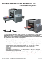
1
Go to table of contents
Maintenance
and
Troubleshooting
DCS_Direct_Jet_1024UV_1014UV_Maintenance_Troubleshooting_Guide_2.1.docx
Notices
The information in this document is subject to change without notice.
NO WARRANTY OF ANY KIND IS MADE WITH REGARD TO THIS MATERIAL, INCLUDING,
BUT NOT LIMITED TO, THE IMPLIED WARRANTIES OF MERCHANTABILITY AND FITNESS
FOR A PARTICULAR PURPOSE.
No liability is assumed for errors contained herein or for incidental damages in connection
with the furnishing, performance, or use of this material.
This document contains proprietary information which is protected by copyright. All rights
are reserved. No part of this document may be photocopied, reproduced, or translated into
another language without prior written consent.
Trademark
Acknowledgements
IBM is a registered trademark of International Business Machines
Corporation. Windows is a trademark of Microsoft Corporation. All other
product and company names mentioned herein are the trademarks of their respective
owners.
Technical
Support
If you require technical assistance, contact a technical representative at 860-829-1027
or email [email protected]
Technical information and downloads are available on our FTP site:
ftp://ftp.directcolorsystems.com/.
The FTP site requires a Login and password.
You will be prompted to put in a user name and password. (If you are not prompted then
double click on a file)
Passwords are as follows and are case sensitive:
Login: dcs
Password: dcsftp
Corporate
Direct Color Systems®
99 Hammer Mill Rd
Rocky Hill, CT 06067
T: 860-829-2244
F: 860-829-2255
Email: [email protected]
Web Site: www.directcolorsystems.com
EAA
Rua do Alto Das Torres, 942
4430-009 Vila Nova De Gaia, Portugal
Email: [email protected]
DCS_Direct_Jet_1024UV_1014UV_Maintenance_Troubleshooting_Guide_2.1.docx
Equipment
Certificate of
Compliance
This Equipment has been tested and found to be within compliance with
CE Compliance:
• Directive 2006/95/EC
Printing
History
Edition 2.1 – February 2013
Addition to FAQs
Printed in the USA
© Copyright 2013, Direct Color, LLC. All rights reserved.
DCS_Direct_Jet_1024UV_1014UV_Maintenance_Troubleshooting_Guide_2.1.docx
Go to table of contents
Table of Contents
SAFETY AND PRECAUTIONS………………………………………………………………………………………6
MAINTENANCE and CLEANING……………………………………………………………………………………8
Daily Maintenance and Cleaning…………………………………………………………………………9
Weekly Maintenance and Cleaning……………………………………………………………………9
Monthly or Periodic Maintenance………………………………………………………………………13
Correcting a Bad Nozzle Check Condition……………………………………………………………15
The Capping Station……………………………………………………………………………………16
Replacing a Direct Jet Print Head………………………………………………………………………27
TROUBLE SHOOTING………………………………………………………………………………………………28
PRINTING - INFO SHEET AND FAQs……………………………………………………………………………37
DCS_Direct_Jet_1024UV_1014UV_Maintenance_Troubleshooting_Guide_2.1.docx
4 | Page
Go to table of contents
Direct Jet 1024UV/1014UV Maintenance and
Troubleshooting Guide
Thank You...
…for choosing a Direct Color Systems® Direct Jet UV printer. Your printer is designed to provide you with
exceptional output quality on a variety of substrates. The Direct Jet's ability to print to many different
materials without the need for surface pre-coating or undercoating represents a sound investment in time
and productivity that will put you ahead of your competition.
Direct Jet printers have many distinct advantages that will help you produce high quality graphics in record time.
• The Direct Jet 1024UV accepts material up to 6" (152 mm) thick and the Direct Jet 1014UV model accepts
material up to 4" (102mm) thick.
• The Direct Jet 1024UV model accepts substrates up to 13" (330 mm) x 24" (610 mm) in size and has
a printable area of 10" (254mm) x 24" (610 mm). The Direct Jet 1014UV model accepts substrates
up to 13" (330 mm) x 14" (356 mm) in size and has a printable area of 10" (254 mm) x 14" (356
mm).
• Innovative Multisolve™ UV-LED inks print and bond to plastic, wood, stone, etc. Using our adhesion
promoter, the inks will bind to many difficult surfaces, such as glass or stainless steel.*
• Prints white ink.
• Prints clear ink.
• A print speed of 2.75 minutes to print an 8" x 10" image bi-directionally at 1440 x 720 dpi / High Speed.
• Exceptional print resolution of up to 5760 dpi.
• Direct Jet UV printers print from any IBM-PC® or compatible computer running Windows® 7 or 8, 32- and 64bit versions using Direct Color Systems' exclusive Color Byte RIP (Raster Image Processing) software.
* All substrates should be tested for image receptivity, adhesion and durability with final acceptance and suitability
determined by the customer. Direct Color Systems® makes no warranty, expressed or implied.
DCS_Direct_Jet_1024UV_1014UV_Maintenance_Troubleshooting_Guide_2.1.docx
5 | Page
Go to table of contents
SAFETY AND PRECAUTIONS
•
•
•
•
•
•
•
•
•
•
•
•
•
•
Please read these guidelines before operating your Direct Jet printer.
Keep all inks, solvents and lubricants out of the reach of children.
Use only approved cleaning agents and solvents and then only for the purposes specified in this
guide.
Use only genuine Multisolve™ UV-LED inks.
Keep inks in a cool, dark and dry location.
Inks must be used in opaque cartridges only.
This printer produces potentially harmful UV light. Protect eyes and skin from exposure.
This printer should be in a well-ventilated area, particularly if used for long periods or in a small
space.
Avoid physical contact with the printer's table and print head while the printer is in operation.
Avoid dropping items or spilling liquids in or on the printer.
Keep hair, jewelry or loose clothing away from the moving parts of the printer.
Lifting this printer by hand requires a minimum of two people.
Do not attempt to repair this machine yourself without prior DCS authorization. Unless specified
in this guide, only qualified service personnel should attempt any disassembly, repair or access
to internal components. If you need to make mechanical adjustments, turn off your printer and
disconnect it from all power and data sources.
Safety Warning: Safety Glasses and gloves should be used whenever filling ink cartridges or
manually cleaning the print head. These symbols will be used throughout this manual as a
reminder to use safety glasses and gloves. Wear protective gear whenever there is
exposure to the inks, regardless of whether a symbol is displayed.
For prolonged exposure, DCS recommends Butyl Black or Ethylene Vinyl Alcohol Copolymer
laminated gloves.
• The Adhesion Promoter should not be used in an enclosed area without
adequate ventilation. RESPIRATORY PROTECTION: If exposure can exceed the
PEL/TLV, use only NIOSH/MSHA approved air-purifying or supplied air
respirator operated in a positive pressure mode per the NIOSH/OSHA 1981
occupational health guidelines for chemical hazards.
Look for helpful hints.
DCS_Direct_Jet_1024UV_1014UV_Maintenance_Troubleshooting_Guide_2.1.docx
6 | Page
Go to table of contents
Below you will find diagrams of the printer and its parts. Be sure to familiarize yourself with all
the individual parts and descriptions of printer as they will be referred to later in this guide.
Control Panel for Direct Jet with Optional Direct Drive
DCS_Direct_Jet_1024UV_1014UV_Maintenance_Troubleshooting_Guide_2.1.docx
7 | Page
Go to table of contents
MAINTENANCE and CLEANING
When powering the printer back on, remember to turn on the main power then wait 5 seconds before
powering up the print engine. This is to allow time for the LED light to calibrate its distance from the print
head.
Although your Direct Jet printer is engineered to provide many years of trouble-free operation, regular
cleaning and periodic maintenance are required to keep your machine running smoothly.
T
A
S
K
O
V
E
R
V
I
E
W
√
√
√
√
√
√
BEGINNING OF THE DAY
Turn on main power (wait 5 seconds)
Inspect spit tray – clean as needed
Shake white ink (before turning on print engine)
Power up the print engine
Achieve a correct nozzle check
Correct missing nozzles if necessary
Page
9
9
9
9
9
15
√
√
√
√
√
√
END OF THE DAY
Achieve a correct nozzle check
Clean gaskets on capping station
Power down print engine
Turn off main power
Check the ink waste tray
Complete Maintenance Log
9
9
40
√
√
√
√
√
√
√
√
√
√
√
BEGINNING OF THE WEEK
Turn on main power (wait 5 seconds)
Shake white ink (before turning on print engine)
Power up the print engine
Reset Waste Ink Pad Counter and power cycle print engine
Inspect spit tray – clean/replace as needed
Clean and lubricate print station X-axis shafts and rails
Clean the UV lamp
Lubricate Y-axis rails
Achieve a correct nozzle check
Clean print head encoder strip for X-axis
Clean the wiper blade
9
9
9
9
9
10
12
12
9
13
13
√
√
√
END OF THE WEEK
Achieve a correct nozzle check
Power down print engine
Turn off main power
9
9
9
9
LONG TERM MAINTENANCE
√
Run a nozzle check once per week (if printer is idle)
9
√
Inspect intake fan filter on UV lamp and replace as necessary
13
√
Replace syringes and filling needles every 28 days
14
√
Clean encoder wheel for Y-axis every 84 days
14
√
Replace capping station every 84 days
16
√
Replace cartridges every 84 days
14
See the Maintenance Log for a printable checklist. You will be required to present a completed
maintenance log for any tech support and warranty requests. Find the printable log at the end of this
document.
DCS_Direct_Jet_1024UV_1014UV_Maintenance_Troubleshooting_Guide_2.1.docx
8 | Page
Go to table of contents
1.
Turn on main power. Power on the printer with the main power switch. Do not turn on
the print engine (green power button) unless specifically instructed.
2.
Inspect Spit Tray. The spit tray should be cleaned of dried ink regularly. Failure to do so
will lead to a buildup of ink that could eventually hit the bottom of the head and cause a
head strike. Remove the ink by wiping with a dry cloth.
3.
Shake the white ink. Cover the bottom of the ink cartridge with a gloved
finger. Shake up and down 4 or 5 times.
4.
Power up the print engine. Press the green button. Power up is complete when the LED
light turns from amber to solid green.
5.
Nozzle Check. Perform a nozzle check from the Color Byte Rip Queue as outlined in your
Getting Started Guide. If the nozzle check is unsatisfactory, try the steps on page 15. Do
not begin printing before you are satisfied with the nozzle check.
6.
Clean gaskets on capping station. Using a cotton swab, clean the edges of the gaskets
of any ink. If dried ink exists, use alcohol on the swab.
7.
Turn off the main power. When the green LED light on the control panel power has
turned to amber, power off the printer with the main power switch.
8.
Check the ink waste tray. The ink waste tray needs to be monitored and if there is
excess ink in the tray, it should be removed with a syringe and filling needle and disposed
of. Otherwise, overflow of the tray is possible. If there is a crust that has built up on the
surface of the pad, it should be replaced. On average, the pad should be replaced every
month.
Weekly Maintenance and Cleaning
9.
Reset Waste Ink Pad Counter and power cycle print engine.
a. In the Color Byte Rip 9 Queue click on the Printer Status and Settings icon.
b. Click on Reset Ink Pad Counter. You must immediately
restart the printer. It cannot be done the following day.
Press the green button and wait until the LED on the
button is amber. This shuts down the print engine power.
Wait 10 seconds and power on the print engine. When the
LED is solid green, resume normal printer operations.
Note
The waste ink pad counter should be reset at least once per week during normal operations. See Reset
Waste Ink Pad Counter in your Maintenance and Troubleshooting Guide. Failure to do so may result in
downtime and the need to contact DCS Technical Support for resolution.
DCS_Direct_Jet_1024UV_1014UV_Maintenance_Troubleshooting_Guide_2.1.docx
9 | Page
Maintenance
Daily Maintenance and Cleaning
Go to table of contents
11. Clean and lubricate print station X-axis shafts and rails. Due to the additional heat
and dryness created by the UV lamp and its fans, it is necessary to clean and lubricate the rails of
the printer often. DCS recommends this be done weekly for moderate users. Heavy users (48 hours/day, 5-6 days/week) should perform this maintenance daily. Use your discretion
and perform this maintenance as needed.
Use a 3-in-1 oil or a light sewing machine oil on the shafts and rails. Use the lithium grease
on the round shaft only.
Locate a spare syringe and filling needle in your printer accessory kit. Fill the syringe with
a small amount of 3-in-1 oil. Use a new syringe and filling needle and label it to
avoid mixing the oil with any inks or wash. The lithium grease can be applied with a
gloved finger.
Move the print head carriage into position
Use the up arrow to raise the print engine to its maximum height. Press
to unlock the
print head carriage. When it has stopped moving, manually move it to the center of the
shaft.
With a lint-free cloth or paper towel soaked in WD-40, polish the round shaft clean.
Also remove any build up around the bushings. Do not spray WD-40 on or near the printer.
Do not let it come into contact with the UV lamp bracket or rails. Use the cloth to clean
the entire shaft from one end to the other.
Slide the print head back and forth. Check that no grease or debris is left on the shaft. If there is,
repeat the cleaning procedure.
DCS_Direct_Jet_1024UV_1014UV_Maintenance_Troubleshooting_Guide_2.1.docx
10 | P a g e
Maintenance
10. Remove build up ink from the spit tray. Wearing gloves, wipe the inside
of the spit tray with a paper towel. Dried ink that is elevated above the edges
should be removed as well. It should break off in your gloved hand, but can
also be scraped off with a tool if necessary. Dispose of the towel in
accordance with local and city ordinances.
Go to table of contents
The outside of
the print head
bushings on both
sides.
It is critical that the
area between the
print head bushings
be lubricated.
Apply the 3-in-1 oil and
then, using a gloved
finger, apply lithium
grease to the same
locations.
Upper and lower rail and
car on both sides of the
UV lamp carriage. Do
not use WD-40 on
the UV lamp rails.
Clean with an IPA
wipe when needed.
Manually move the print head left and right (do not move the lamp, it will follow
along with the print head) to spread the oil along the length of the shaft.
Again, using a gloved finger, apply a light grease (ex: lithium) in the areas indicated
to the print head upper guide.
Use a very small amount of
grease and apply to the
underside of the guide rail.
Apply in several areas, moving the print
head for access when necessary. DO NOT
grab the UV lamp. It will track with the
print head.
Move the print head left and right to ensure even distribution of the grease.
DCS_Direct_Jet_1024UV_1014UV_Maintenance_Troubleshooting_Guide_2.1.docx
11 | P a g e
Maintenance
Apply a drop or two of oil to the areas indicated. Do not over-lubricate.
Go to table of contents
Clean the UV lamp after you've cleaned and
lubricated the rails. The print head carriage is already
in place. Skip right to step b!
a. Press
to unlock the print head carriage. When it has stopped moving, manually
move it to the center of the shaft.
b. Turn off the printer by the main power switch.
c. Spray a general purpose glass cleaner onto a soft lint-free cloth and wipe the glass
covering the UV light. Do not spray cleaner directly onto the lamp. If this does not
clean the glass, dried ink will need to be scraped off. Hold the lamp firmly so that it
does not move during this process. Use a glass scraper
(found in your accessories kit) and gently scrape across the
surface until the glass is clear. Wipe the glass again. Visually
confirm that the lamp has not moved by checking that it is
higher than the print head and that it is parallel to the media
table. Also confirm that the reflectors surrounding the glass
have not been damaged. Replace if they are bent.
12.
Lubricate Y-axis rails. Using WD-40 sprayed on a lint-free cloth, first wipe the Y-axis
rails so they are clean of any debris or lubrication. Apply a drop or two of oil to the media
table rails as indicated. Use the left and right arrow buttons to move the table back and
forth to spread the oil. Do not push the table by hand.
Oil should be applied to the edges only. Do
not apply to the screws.
Apply a drop or two.
Apply the oil to the rails near the
center
Using the arrow keys, move the table to the
opposite end and again, apply oil to the rails
near the center.
Move the table back and forth once more to ensure even distribution of the oil.
DCS_Direct_Jet_1024UV_1014UV_Maintenance_Troubleshooting_Guide_2.1.docx
12 | P a g e
Maintenance
11. Clean the UV lamp. Use the up arrow to raise the print engine to its maximum height.
Go to table of contents
Both sides of the encoder strip used by the print head
should be wiped gently with an IPA wipe (included in
the cleaning kit) in order to remove any debris that may
have fallen on to it during the lubrication process or from
ink residue.
14. Clean the wiper blade. Clean the wiper in the capping station to avoid streaking in your
finished images and/or if drops of ink on the bottom of the head are not being wiped off
after a cleaning cycle.
Monthly or Periodic Maintenance
15. Inspect intake fan filter on UV lamp. Lift the cover. Press
to unlock the print
head carriage. When it has stopped moving, manually move it to the far left of the shaft.
Inspect the fan filter.
Old filter
New filter
Change the intake fan filter
1.
Press
to unlock the print head carriage. When it has stopped moving, manually
move it to the far left of the shaft. Turn off main power.
2.
Remove the 4 screws from the filter
retainer.
DCS_Direct_Jet_1024UV_1014UV_Maintenance_Troubleshooting_Guide_2.1.docx
13 | P a g e
Maintenance
13. Clean the print head encoder strip for the X-axis. Using an IPA wipe, clean the
encoder strip.
Go to table of contents
Discard the old filter.
4.
Clean the retainer and fan guard with a dry cloth if needed.
Maintenance
3.
Fan guard
Retainer
5.
Place the new filter over the fan guard and secure with the retainer and 4 screws.
16. Replace syringes and filling needles every 28 days. No more than every 28 days,
discard all filling syringes and filling needles. Begin using new ones.
17. Clean encoder wheel for Y-axis every 84 days. Clean with an IPA wipe.
18. Every 3 months, replace the capping station. Go to page 16 for instructions.
19. Replace all ink cartridges every 84 days or more often as needed.
DCS_Direct_Jet_1024UV_1014UV_Maintenance_Troubleshooting_Guide_2.1.docx
14 | P a g e
Go to table of contents
1.
If you are unsatisfied with a nozzle check, first run a head clean. Perform a head clean from
the device properties dialog box in the Queue or to perform the head clean from the printer,
hold
2.
for 5 seconds. After the head clean, run another nozzle check.
Check for weeping ink. Look at the bottom of the Print Head to determine if either there is ink
weeping (dripping) from the print head or if no ink is flowing.
Use the up arrow to raise the print engine to its maximum height. Press
to unlock the
print head carriage. When it has stopped moving, manually move it to the center of the
shaft.
3.
a.
b.
c.
Wipe the bottom of the print head with an alcohol wipe so it is clear of ink.
Check the bottom of the head after 5 minutes.
If you see lines of ink form on the print head, remove the cartridges and reseat
the filler caps. Turning the filler cap as you seat it will help it to install more
easily and ensure a tight fit. Reinstall the cartridges and repeat step a. If the
cartridge continues to weep, replace it.
d.
Press
to return the print head to its normal position. Do one print head
cleaning cycle and then a nozzle check.
Check for no ink flow. Check that ink is flowing from the cartridge.
1.
2.
3.
If necessary, press
to return the print head to its normal position.
Remove the filler cap on the cartridge (color) that has the bad nozzle check. This will allow
more ink flow through that head.
Do 2 print head cleaning cycles. Replace the cartridge filler cap. Do a nozzle check. If this
doesn't give a good nozzle check then proceed to Clear a Clogged Nozzle for the Print Head.
Clear a Clogged Nozzle for the Print Head
1.
2.
3.
4.
While running a head clean, inspect the capping station caps to be sure that they
are filling with ink. If the caps do not fill, clean the gasket on the capping station
with a swab. If this doesn't resolve the ability of the capping station to seal, the
capping station should be replaced. DCS recommends replacing the capping
station every 3 months.
Discard the current set of filling syringes, needles and cartridges being used for the
color which is not achieving good nozzle results. Using a new filling needle and
syringe, refill a new cartridge with ink and reinstall in the printer. One or two
cleaning cycles may be needed at that time. Perform a nozzle check again.
Print a large square (approximately 6" or 150mm) image of the color that does not
exhibit a proper nozzle test result. This image may need to be printed several
times to eliminate air bubbles trapped in the head.
If proper nozzle check output is not achieved at this time, contact DCS Technical
Support or your local dealer.
DCS_Direct_Jet_1024UV_1014UV_Maintenance_Troubleshooting_Guide_2.1.docx
15 | P a g e
Maintenance
Correcting a Bad Nozzle Check Condition
Go to table of contents
Maintenance
The Capping Station
Clean the wiper blade
1.
Press
. Manually move the capping station away from the print head.
2.
Pull back on the tab as shown below and
then flip up the wiper. Do not remove
the capping station. The picture is for
demonstration purposes only.
Wiper
Tab
3.
Wearing gloves, wipe the blade clean with an IPA wipe (provided in your cleaning kit). Inspect
the edge of the wiper blade for damage or irregular shaped dried ink that can't be removed
with cleaning. If it cannot be removed, the blade must be replaced. Contact DCS for
instructions for replacing the blade.
4.
Return the blade to its original position.
5.
Press the blue button again.
DCS_Direct_Jet_1024UV_1014UV_Maintenance_Troubleshooting_Guide_2.1.docx
16 | P a g e
Go to table of contents
Replace a Capping Station if:
a. The gaskets no longer form a tight seal around the print heads, and the cleaning cycle does
not perform properly.
b. Some type of physical damage has occurred to the unit.
c. There is an electrical failure of the pump motor.
d. It is more than 90 days old.
Tools Required
Long magnetized Philips head screwdriver
Needle-nose pliers
Time Required
Approximately 20 minutes
The Capping Station is mounted to the printer with 5 Philips head screws (4 hold it in place + 1 for
the orange ground wire). There is also 1 small electrical connector that needs to be disconnected.
1.
Remove the acrylic front cover. Remove the four thumb screws. With assistance, lift the cover
straight up and off of the printer.
2.
Press the up arrow button until the print engine is at its maximum height. Press
off main power. DO NOT PRESS
3.
. Turn
.
Remove the 4 Philips head screws.
DCS_Direct_Jet_1024UV_1014UV_Maintenance_Troubleshooting_Guide_2.1.docx
17 | P a g e
Maintenance
Replace the Capping Station
Go to table of contents
Remove the locking bracket holding the unit to the
side plate. Use pliers to remove the bracket from the
side of the print engine.
Maintenance
4.
Disconnect orange ground wire.
5.
Disconnect the electrical cable that goes to the motor. Do
not leave the gender changer connected to the capping
station. Leave it connected to the wire that is attached
to the printer.
6.
Carefully remove the unit.
7.
Reverse procedure to install the replacement unit.
8.
Select an Initial Charge from the Device Properties screen to get the ink flowing through the
new Capping Station.
DCS_Direct_Jet_1024UV_1014UV_Maintenance_Troubleshooting_Guide_2.1.docx
18 | P a g e
Go to table of contents
This procedure is used for adjusting the X and Y "0" point of the printer to be equal to the Color
Byte software "0" point.
Tools Required
1/16" hex head wrench
3/32" hex head wrench
Time Required
Approximately 20 minutes
1.
Make sure the print engine power is ON (
2.
Load a piece of 8.5" x 11" (or A4) paper or a white substrate of similar size. Use the edge
guides to align it on the left edge of the table.
3.
Open the Color Byte Rip Pro Queue. Select the Color Only queue.
4.
Be sure the table is at Print Home. Go to Devices>Print Test Page. Select the First Dot file and
click OK.
5.
After the file has been imported, click Print.
the green LED is on solid).
DCS_Direct_Jet_1024UV_1014UV_Maintenance_Troubleshooting_Guide_2.1.docx
19 | P a g e
Maintenance
X & Y "0" Calibration Adjustment
Go to table of contents
To adjust the print home sensor, look carefully at the printed picture. Verify that the black line
across the top of the page is parallel and is .500" (12.7mm) thick. Verify that the vertical line is
exactly 1.000" (25.4mm) thick. See below if any of these conditions is not met.
Not Parallel
If the black line across the top is not parallel with the edge of the paper then the Photo
Paper may not have been aligned properly, go back to step 2 and reprint the picture. If you
are sure the paper was aligned properly and the black line does not appear parallel, the print
engine is not aligned with the front edge of the slide table. Contact Direct Color Systems tech
support.
Horizontal line is less than .500"
If the black line is less than .500" then the print home sensor must be moved toward the left
by the difference between the width of the black line and .500".
1. Raise the elevator to its maximum height.
2. Loosen the locking screws holding the sensor.
3. Turn the adjustment screw clockwise to move the
sensor toward the far left position. One full rotation of
the adjustment screw equals approximately .025".
Tighten the locking screws and reprint the test page to
verify the adjustment is correct.
There is a white gap before the horizontal line
If there is a white gap before the .500" thick line then
the start print sensor must be moved toward the right
to close this gap.
1. Raise the elevator to its maximum height.
2. Loosen the locking screws holding the sensor.
3. Turn the adjustment screw counter-clockwise to
move the sensor toward the far left position.
One full rotation of the adjustment screw equals
approximately .025". Tighten the locking screws
and reprint the test page to verify the
adjustment is correct.
DCS_Direct_Jet_1024UV_1014UV_Maintenance_Troubleshooting_Guide_2.1.docx
20 | P a g e
Maintenance
6.
Go to table of contents
There is a white gap before the vertical line
If there is a white gap before the 1.000" thick line then an adjustment must be made to
close this gap. Measure the gap and record the resulting value without decimals. For
example, if the gap is 0.003" thick, record a value of 3.
1. Click on Printer Status and Settings
2. Select "Read First Dot" and record this value
3. Click Yes to change the value
4. Subtract your value from the First Dot value and enter the new value. For example, if
the First Dot value was 35, subtract 3 from that and enter a value of 32.
5. Reprint the Test Page
Note
If the new value that is calculated from these steps exceeds -60 or +60, then the left edge of the Print
Head Engine Assembly must be readjusted. Contact Direct Color Systems Tech support.
DCS_Direct_Jet_1024UV_1014UV_Maintenance_Troubleshooting_Guide_2.1.docx
21 | P a g e
Maintenance
Vertical line is less than 1.000"
If it is less than 1.000", subtract this value from 1.000". Record the resulting value without
decimals. For example, if the line is 0.995" thick, then 1.000 – 0.995 = 0.005. Record a value
of 5. This value must be determined in inches, not millimeters.
1. Click on Printer Status and Settings
2. Select "Read First Dot" and record this value
3. Click Yes to change the value
4. Add your value to the First Dot value and enter the new value. For example, if the
First Dot value was 35, add 5 to that and enter a value of 40.
5. Reprint the Test Page
Go to table of contents
Read all of the instructions prior to execution
When powering the printer back on, remember to turn on the main power then wait 5
seconds before powering up the print engine. This is to allow time for the LED light to
calibrate its distance from the print head.
Tools Required
T-15 Torx driver
.050" Hex Head Driver
3/32" Hex Head Driver
# 1 Philips head screwdriver (customer
supplied)
Head Height Gauge (.040" shim)
provided by DCS
PT-1320-T004 Head Height Tool
provided by DCS
Make sure the print engine power is ON (
Press
Time Required
Approximately 20 Minutes
LED solid green).
and raise the print engine ½" so that there is no chance of damaging the print
head during this procedure. Press
to move the table to print home. Open the Color
Byte Rip Pro Queue. Click OK on the Reminder dialog box that says "Have you performed
your weekly Ink Pad Reset?"
Select Queue from the toolbar; then select Manage Queues from the drop down menu.
Confirm that Epson Stylus
Photo R1900 (any USB
number is OK) is selected.
Click Close. Note, that any
time you connect a
different Direct Jet, you
will have to reselect this
printer option as each
board has its own unique
USB signature.
Click on the Printer Status and Settings icon.
DCS_Direct_Jet_1024UV_1014UV_Maintenance_Troubleshooting_Guide_2.1.docx
22 | P a g e
Maintenance
Print Head and Lamp Height Check
Go to table of contents
Close the Device Properties dialogue box, and go to your Nozzle Check queue. Click on the
preloaded file and print.
The print head will move to the far side. As it returns, turn OFF the printer main AC power
switch when it is approximately halfway. Wait 10 seconds.
Turn the power main AC power switch ON. This will bring power to the printer but not move
the Print Head (amber light is displayed on the green button of the front panel). DO NOT
turn print engine on.
Check for level
Move the media table to the far left. Remove any substrate (and tacky mat) from the media
table. Remove the media guide and lower the edge guides. Move the media table to the far
right. Use SLOW TABLE SPEED by pressing and holding
while pressing
to move
the media table toward the print head, but not under it. If you have a standard drive, you can
push the table with your hand at a slow speed. Do not manually push the table if you have a direct
drive. Place the head height tool on the edge of the table and move the print engine up until
the LED sensor is approximately level with the tool (see picture below). Slide the sensor
stop under the sensor. Approach it from an angle so that the neither the tool nor your hand
blocks the sensor. This will raise the print engine. Do not lower the print engine while
the tool is in place. You may damage the sensor. Without moving the table or print
engine, place the sensor stop under the sensor on the opposite side. If the two sensors are
level, you are done. If not, go to page 25.
DCS_Direct_Jet_1024UV_1014UV_Maintenance_Troubleshooting_Guide_2.1.docx
23 | P a g e
Maintenance
If this is the first time the printer is going to print, make
sure all of the ink cartridges are filled with ink. On the
Device Properties dialogue box, click on Head Clean, and
wait for the printer to finish (The green LED will go from
blinking to solid). Do this 2 more times. This will fill the
print head nozzles with ink.
Go to table of contents
Remove the tool. Press the down arrow button and hold it until the elevator stops, then
release it. This sets the print head height.
Using
and the arrow buttons once again, move the table until it is under the print
head. If you have a standard drive, you can push the table with your hand at a slow speed. Do not
manually push the table if you have a direct drive.
Slide the DCS Head Height Gauge between the Print Head and the Media Table. It should fit
all the way under the head, with very little gap (just enough to slide a piece of paper in
between. Move the head to another point on the axis and check again. Check in several
places. If there is any significant difference at any of these points, contact DCS Tech
Support for adjustment information. If the head height needs adjustment, go to page 25.
Otherwise, if the head is at the proper height, stack the two guides and check the height of
the UV lamp using the same method. If the lamp height needs adjustment, go to page 26.
DCS_Direct_Jet_1024UV_1014UV_Maintenance_Troubleshooting_Guide_2.1.docx
24 | P a g e
Maintenance
Check head height
Go to table of contents
If the LED sensors aren't level, use these
instructions but only adjust one of the
blocks
Manually move the print head carriage toward the capping station. Move the media table to
the far right. Press and hold the down arrow button until the elevator stops moving.
Press and hold
then press
to move the media table toward the print engine until
the front edge of the table is past the LED sensor on the print head assembly. If you have a
standard drive, you can push the table with your hand at a slow speed. Do not manually push the
table if you have a direct drive. See picture below. This will cause the elevator to adjust to the
height of the sensors.
Press and hold
then use the arrow keys to move the media table so the front edge is
under the print head. If you have a standard drive, you can push the table with your hand at a
slow speed. Do not manually push the table if you have a direct drive. Place the print head near
the center of the media table. Slide the Head Height Gauge between the media table and
print head. It should slide easily, but not have a gap larger than the thickness of a piece of
copier paper.
Each full turn of the adjustment screw
equals .010" (0.25mm)
If the Gauge will not fit:
a. Loosen the locking screws on both blocks
b. Turn the adjustment screw counter-clockwise the same
number of turns on both blocks
c. Test the Gauge again and repeat adjustments until satisfied
d. Tighten the locking screws on both blocks.
If the gap is too large:
a. Loosen the locking screws on both blocks
b. Turn the adjustment screw clockwise the same number of
turns on both blocks
c. Test the Gauge again and repeat adjustments until satisfied
d. Tighten the locking screws on both blocks.
DCS_Direct_Jet_1024UV_1014UV_Maintenance_Troubleshooting_Guide_2.1.docx
25 | P a g e
Maintenance
Adjusting the head height
Go to table of contents
Maintenance
UV Lamp Height Adjustment
Always check the head height
before the UV lamp height!
If you have performed and are satisfied with the
head height adjustment, place two shims on the
media table in front of the UV lamp.
Press and hold
then use the arrow keys to move the media table so the shims
are under the lamp. If you have a standard drive, you can push the table with your hand at a
slow speed. Do not manually push the table if you have a direct drive. The lamp should be only
slightly above the shims (enough so that a piece of copier paper can fit).
If the lamp is not at the right height, hold the
lamp and use the hex tools to first loosen the set
screw and then the lamp screw. Do not let the
lamp slide on its own. Move the lamp so that it is
at the proper height then tighten the lamp screw
and then the set screw.
Lamp screw
Set screw
DCS_Direct_Jet_1024UV_1014UV_Maintenance_Troubleshooting_Guide_2.1.docx
26 | P a g e
Go to table of contents
Replace a Print Head if:
1)
Some type of physical damage has occurred to the Print Head unit.
2)
Some electrical problem has occurred with the Print Head unit.
3)
There is a clog in the head that prevents the correct nozzle check pattern to be printed, and
after all attempts at clearing the head, the head will not properly print the correct nozzle
check.
Contact Direct Color Systems for the print head replacement instructions and special tools
needed for replacing the print head.
DCS_Direct_Jet_1024UV_1014UV_Maintenance_Troubleshooting_Guide_2.1.docx
27 | P a g e
Maintenance
Replacing a Direct Jet Print Head
Go to table of contents
If you have difficulty operating the printer, the troubleshooting procedures in this section should, in
most cases, solve the problem. Turning the printer off and back on and rebooting the P.C. (cold
booting the system) may also clear the error. Use the lights on the Control Panel buttons to
determine various error conditions.
Control Panel for Direct Jet with Optional Direct Drive
Control Panel for Standard Drive
Print Engine Condition and LED Status
Printer Status
Power
Power OFF
Flashes at
high speed
Fatal error
OFF
Maintenance request
Media error
Ink cartridge replacement
is in progress
Ink sequence is in progress
Indicators (LEDs)
Error light
Error light
1
2
Priority1
OFF
1
Press
Flashes at
high speed
Flashes at
high speed
2
See below.
OFF
Flashes
alternately
Flashes
alternately
3
--
ON
--
4
The waste ink counter has exceeded its
maximum number. Reset the waste ink pad
counter.
See below.
Flashes
--
--
5
Wait for command to finish.
Flashes
--
--
6
Wait for command to finish.
Install ink cartridges or reseat existing
cartridges.
2
CSIC error
--
--
ON
No ink cartidge error or
ink-out error
--
--
ON2
Data processing
Flashes
--
--
8
Ink level low
Power ON
-Flashes
---
Flashes2
--
9
--
1
2
Solution
7
to turn the print engine on.
See below.
Wait for command (print, nozzle check, head
cleaning) to finish.
See below.
Wait for the light to be solid.
When two or more errors occur at the same time, the one with higher priority will be indicated.
The cartridge LED corresponding to each ink cartridge lights.
DCS_Direct_Jet_1024UV_1014UV_Maintenance_Troubleshooting_Guide_2.1.docx
28 | P a g e
Troubleshooting
TROUBLE SHOOTING
Go to table of contents
There are a number of conditions that will cause a fatal error.
The most common is that the print engine, media table or head assembly was not in the
correct position when the print engine was powered on and tried to perform its self test.
Power the print engine off and the main power supply off. Turn on the main power
supply, wait 5 seconds and then power on the print engine normally to clear this error. If
after 3 times of powering on and off the fatal error continues, the fault may be one of the
items below. Contact Direct Color Systems Technical Support to help diagnose the
problem.
1)
2)
3)
4)
5)
6)
Media error
Y-axis motor not turning.
A) Lost Y-axis encoder feed back
B) Missing 42 volts, Check YACB board for bad 2 amp. Fuse.
ASF motor control error
A) Disconnected cable to ASF motor or sensor.
B) Failed ASF motor or sensor
Auto Platen Gap control error
A) Disconnected cables to APG motor or sensors.
B) Failed APG motor or top or bottom sensor.
Capping Station Pump Motor
Paper Width sensor error
Head temperature error
This condition is caused when a print command was sent to the printer and the media
table was not at print home. To clear, press the Print Home button, then Press the Media
Feed/ Cancel button. This should clear the error and start the print.
No ink cartridge error
One or more ink cartridges are not installed or installed incorrectly (wrong slot) or the
cartridge chip is reading ink out. Press
and the Print Station will move to an
accessible position for ink cartridge installation. Open the cover. Determine which
cartridge has the problem by viewing the LEDs above the cartridge carriage. The lit one
indicates the problem cartridge. Remove and check the cartridge for the proper number
cartridge for that slot, also check for ink or debris on the cartridge chip, clean if needed.
Install cartridge making sure it clicks into the cartridge head. Press
printer to complete the ink cartridge load cycle.
Ink low
and allow the
This condition will stop operations. Press
and the Print Station will move to an
accessible position for ink cartridge installation. Open the cover. Determine which
cartridge has the problem by viewing the LEDs above the cartridge carriage. The lit one
indicates the problem cartridge. Remove the cartridge. If necessary, fill and reset it before
reinserting. Press
and allow the printer to complete the ink cartridge load cycle.
DCS_Direct_Jet_1024UV_1014UV_Maintenance_Troubleshooting_Guide_2.1.docx
29 | P a g e
Troubleshooting
Fatal error
Go to table of contents
Use the following table to indentify and fix Mechanical and Electrical faults
Symptoms
The UV light is not lit.
Check
The light will automatically shut off when the
temperature exceeds 104°F (40°C). It will turn
back on automatically when the operating
temperature has returned to an acceptable value.
The filter. If it is dirty, it will reduce air flow and
can cause high temperature leading to automatic
shut down.
Switch AC main power on.
No lights on the control
panel and no table or
elevator movement when
control panel buttons are
pressed.
Replace
The ambient temperature.
Check AC power cord.
The filter
Replace power cord.
Check AC power source (wall plug).
Change AC power
source.
Check AC power fuses.
Replace AC power fuses
Replace Printer Power
Supply
DCS_Direct_Jet_1024UV_1014UV_Maintenance_Troubleshooting_Guide_2.1.docx
30 | P a g e
Troubleshooting
Hardware Troubleshooting Guide
Go to table of contents
Check
Check and verify print home (table control lock)
has not been pressed (See Print Home
Description).
Pressing Control Panel
buttons: Left Arrow, Right
Arrow, or Print Home
doesn't move the media
table.
Check and reseat cable connected to CN3 on the
YACB board.
Check and reseat cable connected to CN11 on
the YACB board.
Check F1, 42 VDC fuse on the YACB board.
Check F2, 5 VDC fuse on the YACB board.
Replace
Replace 42 VDC 2 Amp
Fuse.
Replace 5 VDC 1 Amp.
Fuse.
Replace YACB Board.
Replace Y-axis motor.
Replace Printer Power
Supply
Check the Y-axis motor and gear train.
Replace 24 VDC 2 Amp.
Fuse.
Pressing Control Panel
buttons: Up Arrow and
Down Arrow, doesn't move
the print engine elevator
up or down.
Check and reseat cable connected to CN1 on the
EIB board and the Z-axis motor.
Check 24VDC fuse on the EIB board.
Check Z-axis Limit sensors, motor and gear train.
Replace EIB board.
Replace Z-axis motor.
Replace Z-axis Limit
sensor.
Replace Printer Power
Supply
DCS_Direct_Jet_1024UV_1014UV_Maintenance_Troubleshooting_Guide_2.1.docx
31 | P a g e
Troubleshooting
Symptoms
Go to table of contents
Check
Replace
If you have shut the printer down abnormally,
you will need to press the green button again to
clear the fatal error. The amber light should light
on the green button. Make sure the table is all
the way to the right and then press the green
button. You may have to do this up to 3 times to
clear this error.
If the fatal error continues to occur check the
following:
1.
When pressing the green
button with the amber
light lit, after a short time
#1 & #2 LED's turn on and
flash at a 1 second rate.
This is a fatal error.
CR motor not turning (Print Head Motor).
A.
Missing 42 volts, check EIB F3, 42 volt
.75 amp fuse.
B.
Check the CR motor connector at the
motor end and at the Epson bd.
Replace EIB 42 volt
Fuse.
Replace CR motor.
The ASF assembly in the DSC configuration is the
motor, a haft moon disc attached to the motor,
and the sensor. It mimics the feed roll operation
of the Epson printer.
Replace ASF sensor.
2.
Replace ASF motor.
ASF motor control error.
A.
3.
Check the sensor and motor
connectors and cables.
Auto Platen Gap control error.
A.
Check APG sensors and motor
connectors and cables.
Replace upper or lower
sensor.
Replace APG motor.
DCS_Direct_Jet_1024UV_1014UV_Maintenance_Troubleshooting_Guide_2.1.docx
32 | P a g e
Troubleshooting
Symptoms
Go to table of contents
Capping Station Pump motor.
Note: Loud grinding noise will occur in addition
to flashing lights.
When pressing the green
button with the amber
light lit, after a short time
#1 & #2 LED's turn on and
flash at a 1 second rate.
This is a fatal error.
5.
6.
A.
Check Pump motor connector.
B.
Check gear train position in capping
station.
Replace capping station.
Paper Width sensor
A.
Check and or clean Width Sensor.
B.
Check for strong overhead light
reflecting into sensor.
Head temperature error
Replace Width sensor
cover.
Replace print head.
Replace Epson board.
Troubleshooting a fatal error
Use this sequence to follow the startup procedure and try to determine which item might be failing.
The last step completed before getting the fatal error is where the error occurred. This is where
you should look to determine what in the above table should be done to correct the problem.
The carriage unit is in the home position with the CR locked.
Press
to begin the sequence.
1. The drive of the APG Motor is transmitted to the Carriage Shaft, and Carriage Unit (Print Head) will lift
up a little.
2. The drive of the CR motor is transmitted to the Carriage Unit, and the Carriage Unit performs Head
Position detection operation in the following path.
• The Carriage Unit Verifies that it's at the Home Position > It tries to move Right > then moves left
to confirm Carriage Unit lock position > Then moves Right to Home position.
3. The drive of the Pump Motor is transmitted to the Cap Unit, the Cap opens (lowers), and the Carriage
Lock is released.
4. After the Carriage Unit has moved leftward by the specified number of steps, the Wiper, driven by the
Pump Motor, performs the following.
• Wiper Setting > Wiper resetting.
5. The Carriage Unit returns to home position. And the APG Motor lowers the Carriage Unit to its normal
position.
6. The drive of the PF Motor is transmitted to the Media Table Drive, which then rotates for about 2
seconds (moves the Media Table about 2" at slow speed).
7. The ASF motor is rotated (this is the motor with the half moon disc on it).
8. Then the Carriage Unit moves between the left and right frames twice, the Carriage Unit moves to the
right end of the print carriage rod near the control panel. This calibrates the width sensor in the print
head.
9. The PF Motor rotates moving the media table.
• Rotation for about 4 seconds (slow speed) > Rotation for about 2 seconds
10. The Carriage Unit returns to the home position and is secured by the CR Lock.
11. The green LED on the Green button lights solid.
DCS_Direct_Jet_1024UV_1014UV_Maintenance_Troubleshooting_Guide_2.1.docx
33 | P a g e
Troubleshooting
4.
Go to table of contents
Check
Replace
Check Print Head Height (See Head Height
Adjustment)
Check that all items on the table are of a similar
height.
Check for Static on Substrate (Use Novus
Cleaner)
Over Spray on the print
Check Nozzle Check Pattern for Correct spray
Check Print Head for drips on the bottom of the
Print Head
Replace Small Waste
Pad.
Replace Print Head.
Check for Small Waste Pad touching the Print
Head
Check Print Head ID# to be the same on Print
Head as read from the software.
Check Nozzle Check Pattern for Correct spray.
Check Print Head Height (See Head Height
Adjustment)
Check Print Head ID# to be the same on Print
Head as read from the software.
Horizontal banding in the
Image being printed
Check Media Table speed to make sure it is not
to slow and causing erratic table movement.
Check and make sure the printer platform is
stable and doesn't move or shake when the
printer is printing.
Replace Y-axis motor
assembly.
Replace rail bearings
and or rails.
Replace Print Head
Clean Encoder Disc on Y-axis drive.
Increase Max Ink or DPI to improve image
quality.
DCS_Direct_Jet_1024UV_1014UV_Maintenance_Troubleshooting_Guide_2.1.docx
34 | P a g e
Troubleshooting
Symptoms
Go to table of contents
Troubleshooting
During Normal Operation the capping
station should last 3 months on average.
Normal operation is running the printer 8
hours a day, 5 days a week.
Why does the capping station fail? The
reason the capping station fails is because
the solvents in the ink and cleaning solutions
dry out the rubber gasket that is used to seal
against the print head. This gasket is used to
create a vacuum that pulls air and dried ink
from the print head nozzles.
Premature Failure of the
Capping Station
There are a number of items that can
accelerate the failure of the capping station:
Capping station failing
sooner than 3 months
2.
Failing to put the filler cap tightly
on the cartridge. This will allow an
excessive amount of ink to flow through
the nozzle and into the capping station.
3.
Filling the cartridges while they are
still in the Print Head. This should
never be done because when the filler
cap on the cartridge is removed, the
valve on the bottom of cartridge is still
open. This will allow an excessive
amount of ink to flow through the
nozzle and into the capping station.
This will continue even after the filler
cap is replaced and will cause the ink to
continue to drip through the head.
Another concern is that the inks are
conductive and if spilled can damage
the electrical connection in the print
head.
4.
If the cap in the capping station is
mispositioned. The cap in the capping
station is spring loaded and should float
to the level of the print head during
cleaning. If the cap is pushed out of
position by cleaning with a swab or
some other means, it will not seat
against the print head properly and not
operate correctly.
DCS_Direct_Jet_1024UV_1014UV_Maintenance_Troubleshooting_Guide_2.1.docx
35 | P a g e
Go to table of contents
The printed image is faint or has gaps
Possible Cause
Solution
1. The gap between the head and
substrate is too large
1. Press the down button until the Z axis sensor touches the substrate; release the
button when you hear a clicking noise and the stepper motor stops. The Print Head
Assembly goes up again automatically.
2. Nozzles are clogged
2. Run a nozzle check to confirm if ink is flowing. If output is faulty, perform a cleaning
operation. If it is still not correct, check the following:
• Ensure there is ink in the cartridge(s).
• When performing a cleaning cycle, observe the amount of ink in the caps of the
capping station. If there is very little ink in the caps, you may need to replace the
capping station. Look for instructions on this procedure later in this manual.
3. If printing on paper, the paper may
be damp, curled, or loaded printing
side down
3. Use only dry, flat paper securely loaded with the printing side up.
4. The ink is not compatible with the
substrate
5. Use only substrates to which the ink is able to bond.
The printed image has a halo or faded outline around the image
Possible Cause
Solution
1. Static on plastic substrate
1. Wipe down the substrate lightly with an alcohol wipe.
The printed image has excessive debris, dots or lint in the image
Possible Cause
Solution
1. Airborne dust settling on the
substrate
1. Ensure that the printer's cover is installed at all times during printing.
2. Airborne dust settling on the Media
table or Printer.
2. Remove with an absorbent cloth or blow out with compressed air.
3. Lint left over from paper towels or
"lint-free" cloths.
3. Use only lint-free micro-fiber cloths for wiping and glass cleaner or similar mild
cleaning agent.
Vertical banding is present in the printed image
Possible Cause
Solution
1. The horizontal encoding film is dirty
1. Clean the encoding film with an IPA wipe from the printer’s cleaning kit.
The following
i.
ii.
iii.
iv.
v.
vi.
vii.
viii.
ix.
x.
has a criteria impact on consistent image location and/or pass to pass registration:
Encoder strip cleanliness
Page size and printer size of job
Table printer is placed on
Motor speed
Invoke lead in smoothing in the printer options
Parts in fixture or on table held tight
Table clunking at end of path (motor speed too high)
Power cycle the print engine for any weight change greater than 1 lb
All mechanical parts of drive train are secure and tight
Table moves smoothly when moved by hand along linear motion guides
DCS_Direct_Jet_1024UV_1014UV_Maintenance_Troubleshooting_Guide_2.1.docx
36 | P a g e
Troubleshooting
Print quality and Ink Supply Problems
PRINTING - INFO SHEET AND FAQs
Q:
Why do I have shadows or halos around my image?
A:
The print head is too high or there is too much static electricity. Make sure the print head height is set
correctly and that you have cleaned the substrate with an alcohol wipe prior to printing.
Q:
How will I be able to check to see if the clear ink is flowing through the head?
Q:
Do I have to use a bi-directional print mode for priming?
Q:
Why should I use the same resolution for priming and printing?
A:
A:
Using a glossy PVC or similar material will allow you to view the clear ink with a nozzle check. Photo
paper or regular paper will not work. Follow the procedure in your Getting Started Guide.
You can prime in any of the White Print modes, uni- or bi-directional. In any case, it is recommended
that you print in the same resolution as you prime in and in the same direction if possible.
A:
You can expect fine detail and precise application of inks with Direct Jet UV printers. As a result, if the
resolution for priming is different than that for printing, you may notice a different start point. This is
usually not a problem when creating full-bleed images.
Q:
When should I use the adhesion promoter?
Q:
Even with the adhesion promoter, the ink is not adhering. What should I do?
Q:
How can I print larger images on rounded objects?
A:
A:
The adhesion promoter will be most useful on non-porous surfaces like metal, glass, ceramic and rubber.
In addition to using the promoter, try reducing the amount of ink (starting with the clear). A thinner
layer will be harder to get under and scrape off. Always allow the printed product to cure completely for
24 hours before testing adhesion.
A:
When printing to round objects (golf balls, bottles, etc.) eliminate the small dots and use a mixture of
medium and large dots. This will help get a larger radius. Be aware, though, that it will also mean that
more ink is laid down and you may see slight color shifts. Contact Direct Color's Tech Support
department for custom print modes.
Q:
What is the maximum curve an object can have and still be printed on?
Q:
What is the necessary table space for the printer?
Q:
What tools are required for maintenance?
Q:
What start-up/shutdown procedures are necessary?
Q:
Do the inks require special storage?
A:
A:
A:
A:
A:
On a golf ball, you can print up to a 7/8" diameter logo. Other items are subject to your testing.
The Direct Jet 1024UV measures approximately 33" wide x 50" long (838mm x 1270mm). The table
should be at least this large so that all of the leveling feet make full contact with the table. The table
should be placed with space around it sufficient that all sides of the printer can be easily accessed. The
1014UV is the same width, but does not require the same length.
A Philips screwdriver, several Allen wrenches and a few special tools are all provided with the printer.
Shake the white ink prior to turning on the printer. Prior to filling the white ink cartridge, invert the white
ink bottle and shake vigorously. Other daily and periodic maintenance procedures are outlined in 3.1.
Yes. The inks should be stored at room temperature in the supplied ink box and inside a cabinet with no
light.
DCS_Direct_Jet_1024UV_1014UV_Maintenance_Troubleshooting_Guide_2.1.docx
37 | P a g e
Q:
Do the inks have a "use by" date?
Q:
How do I refill the inks?
Q:
How often do I refill the inks?
Q:
What substrates can I print to? Are there any made specifically for the UV printer?
Q:
Which of my printed substrates can be kept outdoors?
Q:
Can I clean finished pieces with standard cleaning products (Windex®, Pledge®, etc.)?
Q:
How long does it take to print an 8"x10" (203mm x 254mm) image?
Q:
What is the largest object that can be printed on?
Q:
What is the maximum resolution that this printer will print?
Q:
How long is the warranty and what does it cover?
Q:
What parts will need to be periodically replaced? How often?
A:
A:
A:
A:
A:
A:
A:
A:
A:
A:
Inks are viable for 12 months from DOM and 6 months after opening.
See section Filling Ink Cartridges, in the Getting Started Guide.
Inks will need to be refilled depending on the amount of printing you do and the print modes that you
use. On average, you will need to refill every day or two. It is recommended that you fill and reset all ink
cartridges at the end of the day or the start of the next in order to minimize down time.
DCS recommends that all substrates be tested and approved before beginning a job. However, with the
use of our Adhesion Promoter, we have successfully printed to glass, brass, aluminum, silver, and
stainless steel. Without Promoter, we have also printed to PVC, acrylic, plastic and sealed wood. Because
the Direct Jet UV printers print to nearly all standard materials, there are very few "custom" materials
being made for it.
All. The inks are UV stable.
Yes. The UV inks are resistant to cleaners and solvents.
Again, this is print mode dependent. Consult the current DCS Product Catalog for a complete list of
printer metrics.
The 1024UV can print on an object 13"w x 24"l x 6"h (330mm x 610mm x 152mm) and the 1014UV can
print 13"x14"x4" (330mm x 356mm x 102mm). Please note, however, that the required 3" (76mm) left
margin means that the image printed can only be 10" (254mm) wide.
5760 x 1440 dpi
The printer comes with a one year parts and labor standard warranty. This does not warranty
against normal wear and tear. Extended warranties are available for purchase for domestic
customers only. Extended warranties can be purchased for parts only or for parts and labor.
A:
You should expect to replace the capping station 3-4 times per year. Heavy users (daily usage, 4-8
hours) may need to replace the print head once per year. Lighter users may need to replace the print
head once every two years.
Q:
What is the drying/curing time for the ink?
A:
The ink is dried virtually instantaneously after printing due to the curing of the UV LED light at the side of
the print head.
DCS_Direct_Jet_1024UV_1014UV_Maintenance_Troubleshooting_Guide_2.1.docx
38 | P a g e
Q:
Can the UV inks cure without being exposed to the LED light?
Q:
How do I properly sense the height of clear materials?
Q:
How do I properly store my filling needles and syringes?
Q:
Should I use a new filling needle and syringe every time I fill my ink cartridges?
Q:
What do I do if I run out of ink during a print job?
A:
A:
A:
A:
A:
They can over a long period of time. This is why it is important to swap out your syringes every 28 days
and cartridges every 84 days. Continued exposure to overhead and natural light during the filling process
will eventually create contaminants in the form of dried ink. These cured inks are solvent resistant so
using a wash will not get rid of them.
When printing to clear substrates, such as acrylic, glass and crystal, it is necessary to tape the edges.
Otherwise, the LED will not sense the material. Som e crystal and acrylic products are not a
uniform thickness throughout. In these cases, it is recommended that you apply a transfer tape or
similar to the entire surface and over the edges of the material. Use the slow button with the left and
right arrows if you have a Direct Drive Stepper Motor. This will assure that no head strikes will occur
during printing.
New filling needles and syringes can be stored anywhere. Once they have been used and have ink
residue on them, it is important that they be stored in a light-tight box. For best results, use the provided
cardboard ink box and store the box in a light-tight cabinet as well. Do not store the needles and
syringes in an air-tight box .
No. It is only necessary to use a new filling needle and syringe every 84 days. However, after filling a
cartridge, be sure to pump the syringe into the trash to discharge as much "old" ink as possible.
If you run out of ink during the job, you have a small window (approximately 2 minutes) in which
to change the cartridges before there is an error and you will have to reprint the job. In order to
accomplish this in such a short time: 1) have a complete spare set of full cartridges available, 2)
make sure the chips are reset, 3) change all of the inks at the same time so you ensure you do
not run out again during the same job. If the job is nearly complete, you may be able to squeeze
a little more ink out of the cartridge by removing the cartridge and reseating it: press the blue
button, lift the cartridge up, reinsert, press the blue button again. There is very little ink in the
cartridge at this point, so only try this method in an emergency.
See the Quick Reference Guide for information about unpacking your printer and readying it for
setup.
See the Getting Started Guide for help installing software and preparing your printer for first use.
See the Software Guide for information and tips on designing, print modes and printing.
DCS_Direct_Jet_1024UV_1014UV_Maintenance_Troubleshooting_Guide_2.1.docx
39 | P a g e