1
Using FreeHand MX
Macromedia FreeHand MX
Copyright © 1988 - 2003 Macromedia, Inc. All rights reserved.
This manual, as well as the software described in it, is furnished under a license and may not be copied, photocopied,
reproduced, translated, or converted to any electronic or machine-readable form in whole or in part without prior written
approval of Macromedia, Inc. Macromedia, Inc. assumes no responsibility or liability for any errors or inaccuracies that may
appear in this manual.
Trademarks
Allaire, Authorware, ColdFusion, Contribute, Director, Dreamweaver, Fireworks, Flash, Fontographer, FreeHand, HomeSite,
Jrun, Kawa, Macromedia, Macromedia M Logo & Design, Macromedia Contribute, Macromedia Flash, Macromedia Flash
Communication Server, Macromedia Flash Remoting, Roundtrip, Roundtrip HTML, SoundEdit, Shockwave, UltraDev, what
the web can be and Xtra are trademarks of Macromedia, Inc. and may be registered in the United States or in other jurisdictions
including internationally. Macromedia, Inc. does not waive any rights to any Macromedia trademark, service mark, trade name,
product name, or logo that does not appear on this list. Third party trademarks, trade names, product names and logos,
contained in this manual may be the trademarks or registered trademarks of their respective owners.
This guide contains information related to third-party products and services that are not under the control of Macromedia.
Macromedia provides this information only as a convenience, and the inclusion of such information does not imply that
Macromedia endorses or accepts any responsibility for the content or performance of such third-party products and services.
Apple Disclaimer
APPLE COMPUTER, INC. MAKES NO WARRANTIES, EITHER EXPRESS OR IMPLIED, REGARDING THE
ENCLOSED COMPUTER SOFTWARE PACKAGE, ITS MERCHANTABILITY OR ITS FITNESS FOR ANY
PARTICULAR PURPOSE. THE EXCLUSION OF IMPLIED WARRANTIES IS NOT PERMITTED BY SOME
STATES. THE ABOVE EXCLUSION MAY NOT APPLY TO YOU. THIS WARRANTY PROVIDES YOU WITH
SPECIFIC LEGAL RIGHTS. THERE MAY BE OTHER RIGHTS THAT YOU MAY HAVE WHICH VARY FROM
STATE TO STATE.
Part Number ZFH11M100
Acknowledgments
Writers: Dale Crawford and Tonya Estes
Editors: Mary Ferguson, Rosana Francescato, Rebecca Godbois, and Anne Szabla
Managing Editor: Rosana Francescato
Documentation Manager: Gary White
Production: Chris Basmajian, Aaron Begley, Caroline Branch, and Benjamin Salles
Production Manager: Patrice O’Neill
Special thanks to Melana Orton, Delores Highsmith, David Spells, David Morris, and David Halpin.
Macromedia, Inc.
600 Townsend St.
San Francisco, CA 94103
CONTENTS
INTRODUCTION
Getting Started . . .
.................................................. 7
System requirements . . . . . . . . . . . . . . . . . . . . . . . . . . . . . . . . . . . . . . . . . . . . . . . . . . . . 7
Installing and starting FreeHand . . . . . . . . . . . . . . . . . . . . . . . . . . . . . . . . . . . . . . . . . . . 8
Uninstalling FreeHand . . . . . . . . . . . . . . . . . . . . . . . . . . . . . . . . . . . . . . . . . . . . . . . . . . 8
Resources for learning FreeHand . . . . . . . . . . . . . . . . . . . . . . . . . . . . . . . . . . . . . . . . . . . 9
What’s new in FreeHand MX . . . . . . . . . . . . . . . . . . . . . . . . . . . . . . . . . . . . . . . . . . . . 10
CHAPTER 1
FreeHand Basics
. . . . . . . . . . . . . . . . . . . . . . . . . . . . . . . . . . . . . . . . . . . . . . . . . . 13
About vector graphics and bitmap images . . . . . . . . . . . . . . . . . . . . . . . . . . . . . . . . . . .
The Macromedia Studio MX interface . . . . . . . . . . . . . . . . . . . . . . . . . . . . . . . . . . . . .
The Document window . . . . . . . . . . . . . . . . . . . . . . . . . . . . . . . . . . . . . . . . . . . . . . . .
Using panels . . . . . . . . . . . . . . . . . . . . . . . . . . . . . . . . . . . . . . . . . . . . . . . . . . . . . . . . .
Using toolbars . . . . . . . . . . . . . . . . . . . . . . . . . . . . . . . . . . . . . . . . . . . . . . . . . . . . . . . .
Using preferences . . . . . . . . . . . . . . . . . . . . . . . . . . . . . . . . . . . . . . . . . . . . . . . . . . . . .
Using tooltips . . . . . . . . . . . . . . . . . . . . . . . . . . . . . . . . . . . . . . . . . . . . . . . . . . . . . . . .
Using and managing Xtras. . . . . . . . . . . . . . . . . . . . . . . . . . . . . . . . . . . . . . . . . . . . . . .
Setting the document view . . . . . . . . . . . . . . . . . . . . . . . . . . . . . . . . . . . . . . . . . . . . . .
Using the right mouse button (Windows) . . . . . . . . . . . . . . . . . . . . . . . . . . . . . . . . . . .
Printing a shortcut quick-reference card . . . . . . . . . . . . . . . . . . . . . . . . . . . . . . . . . . . .
Customizing your environment . . . . . . . . . . . . . . . . . . . . . . . . . . . . . . . . . . . . . . . . . . .
CHAPTER 2
Setting Up Your Document
13
14
15
15
22
25
27
27
28
33
35
35
. . . . . . . . . . . . . . . . . . . . . . . . . . . . . . . . . . . . . . . . . 43
Using the Document panel . . . . . . . . . . . . . . . . . . . . . . . . . . . . . . . . . . . . . . . . . . . . . .
Working with pages. . . . . . . . . . . . . . . . . . . . . . . . . . . . . . . . . . . . . . . . . . . . . . . . . . . .
Working with master pages . . . . . . . . . . . . . . . . . . . . . . . . . . . . . . . . . . . . . . . . . . . . . .
Using the rulers . . . . . . . . . . . . . . . . . . . . . . . . . . . . . . . . . . . . . . . . . . . . . . . . . . . . . . .
Using the grid and guides . . . . . . . . . . . . . . . . . . . . . . . . . . . . . . . . . . . . . . . . . . . . . . .
Creating and opening documents . . . . . . . . . . . . . . . . . . . . . . . . . . . . . . . . . . . . . . . . .
Linking and embedding . . . . . . . . . . . . . . . . . . . . . . . . . . . . . . . . . . . . . . . . . . . . . . . .
Handling font substitution . . . . . . . . . . . . . . . . . . . . . . . . . . . . . . . . . . . . . . . . . . . . . .
Sending mail (Windows). . . . . . . . . . . . . . . . . . . . . . . . . . . . . . . . . . . . . . . . . . . . . . . .
Using AppleScript to automate FreeHand (Macintosh) . . . . . . . . . . . . . . . . . . . . . . . . .
Working with wizards (Windows) . . . . . . . . . . . . . . . . . . . . . . . . . . . . . . . . . . . . . . . . .
43
44
50
52
54
58
62
65
67
67
68
3
CHAPTER 3
Drawing . . . . . .
. . . . . . . . . . . . . . . . . . . . . . . . . . . . . . . . . . . . . . . . . . . . . . . . . . . . . 69
About vector graphics . . . . . . . . . . . . . . . . . . . . . . . . . . . . . . . . . . . . . . . . . . . . . . . . . . 69
Drawing rectangles, ellipses, and lines . . . . . . . . . . . . . . . . . . . . . . . . . . . . . . . . . . . . . . 74
Drawing polygons and stars. . . . . . . . . . . . . . . . . . . . . . . . . . . . . . . . . . . . . . . . . . . . . . 77
Drawing spirals and arcs . . . . . . . . . . . . . . . . . . . . . . . . . . . . . . . . . . . . . . . . . . . . . . . . 79
Drawing freeform paths. . . . . . . . . . . . . . . . . . . . . . . . . . . . . . . . . . . . . . . . . . . . . . . . . 81
Drawing with the Pen tool and Bezigon tool . . . . . . . . . . . . . . . . . . . . . . . . . . . . . . . . . 84
Editing paths . . . . . . . . . . . . . . . . . . . . . . . . . . . . . . . . . . . . . . . . . . . . . . . . . . . . . . . . . 86
Creating charts and pictographs . . . . . . . . . . . . . . . . . . . . . . . . . . . . . . . . . . . . . . . . . . 96
Dynamically linking objects . . . . . . . . . . . . . . . . . . . . . . . . . . . . . . . . . . . . . . . . . . . . 102
Drawing with the Graphic Hose tool. . . . . . . . . . . . . . . . . . . . . . . . . . . . . . . . . . . . . . 103
CHAPTER 4
Working with Objects.
. . . . . . . . . . . . . . . . . . . . . . . . . . . . . . . . . . . . . . . . . . . . . 107
Using the Object panel . . . . . . . . . . . . . . . . . . . . . . . . . . . . . . . . . . . . . . . . . . . . . . . . 107
Selecting objects . . . . . . . . . . . . . . . . . . . . . . . . . . . . . . . . . . . . . . . . . . . . . . . . . . . . . 109
Moving objects . . . . . . . . . . . . . . . . . . . . . . . . . . . . . . . . . . . . . . . . . . . . . . . . . . . . . . 112
Copying objects. . . . . . . . . . . . . . . . . . . . . . . . . . . . . . . . . . . . . . . . . . . . . . . . . . . . . . 115
Grouping objects. . . . . . . . . . . . . . . . . . . . . . . . . . . . . . . . . . . . . . . . . . . . . . . . . . . . . 119
Arranging objects . . . . . . . . . . . . . . . . . . . . . . . . . . . . . . . . . . . . . . . . . . . . . . . . . . . . 123
Adding names and notes to objects . . . . . . . . . . . . . . . . . . . . . . . . . . . . . . . . . . . . . . . 124
Making global changes . . . . . . . . . . . . . . . . . . . . . . . . . . . . . . . . . . . . . . . . . . . . . . . . 124
Combining paths. . . . . . . . . . . . . . . . . . . . . . . . . . . . . . . . . . . . . . . . . . . . . . . . . . . . . 127
Working with clipping paths . . . . . . . . . . . . . . . . . . . . . . . . . . . . . . . . . . . . . . . . . . . . 132
Expanding a path . . . . . . . . . . . . . . . . . . . . . . . . . . . . . . . . . . . . . . . . . . . . . . . . . . . . 134
Insetting a path . . . . . . . . . . . . . . . . . . . . . . . . . . . . . . . . . . . . . . . . . . . . . . . . . . . . . . 135
Transforming objects . . . . . . . . . . . . . . . . . . . . . . . . . . . . . . . . . . . . . . . . . . . . . . . . . . 136
Undoing actions . . . . . . . . . . . . . . . . . . . . . . . . . . . . . . . . . . . . . . . . . . . . . . . . . . . . . 145
Changing default attributes . . . . . . . . . . . . . . . . . . . . . . . . . . . . . . . . . . . . . . . . . . . . . 146
CHAPTER 5
Working with Color . . .
. . . . . . . . . . . . . . . . . . . . . . . . . . . . . . . . . . . . . . . . . . . . . 147
Applying color to objects. . . . . . . . . . . . . . . . . . . . . . . . . . . . . . . . . . . . . . . . . . . . . . . 147
Spot and process colors . . . . . . . . . . . . . . . . . . . . . . . . . . . . . . . . . . . . . . . . . . . . . . . . 149
Color spaces . . . . . . . . . . . . . . . . . . . . . . . . . . . . . . . . . . . . . . . . . . . . . . . . . . . . . . . . 149
Using the Color Mixer panel . . . . . . . . . . . . . . . . . . . . . . . . . . . . . . . . . . . . . . . . . . . . 150
Using the Tints panel . . . . . . . . . . . . . . . . . . . . . . . . . . . . . . . . . . . . . . . . . . . . . . . . . 152
Using the Swatches panel. . . . . . . . . . . . . . . . . . . . . . . . . . . . . . . . . . . . . . . . . . . . . . . 153
Editing colors . . . . . . . . . . . . . . . . . . . . . . . . . . . . . . . . . . . . . . . . . . . . . . . . . . . . . . . 161
Exporting colors . . . . . . . . . . . . . . . . . . . . . . . . . . . . . . . . . . . . . . . . . . . . . . . . . . . . . 164
CHAPTER 6
Using Strokes and Fills
. . . . . . . . . . . . . . . . . . . . . . . . . . . . . . . . . . . . . . . . . . . . 165
Adding strokes and fills to objects . . . . . . . . . . . . . . . . . . . . . . . . . . . . . . . . . . . . . . . . 165
Applying attributes to strokes . . . . . . . . . . . . . . . . . . . . . . . . . . . . . . . . . . . . . . . . . . . 166
Applying attributes to fills . . . . . . . . . . . . . . . . . . . . . . . . . . . . . . . . . . . . . . . . . . . . . . 177
4
Contents
CHAPTER 7
Special Effects . .
. . . . . . . . . . . . . . . . . . . . . . . . . . . . . . . . . . . . . . . . . . . . . . . . . . 193
Adding live special effects to objects . . . . . . . . . . . . . . . . . . . . . . . . . . . . . . . . . . . . . .
Extruding objects . . . . . . . . . . . . . . . . . . . . . . . . . . . . . . . . . . . . . . . . . . . . . . . . . . . .
Working with blends . . . . . . . . . . . . . . . . . . . . . . . . . . . . . . . . . . . . . . . . . . . . . . . . . .
Adding points to objects or paths . . . . . . . . . . . . . . . . . . . . . . . . . . . . . . . . . . . . . . . .
Roughening objects or paths . . . . . . . . . . . . . . . . . . . . . . . . . . . . . . . . . . . . . . . . . . . .
Applying a fisheye lens effect . . . . . . . . . . . . . . . . . . . . . . . . . . . . . . . . . . . . . . . . . . . .
Bending or bloating objects or paths . . . . . . . . . . . . . . . . . . . . . . . . . . . . . . . . . . . . . .
Creating perspective . . . . . . . . . . . . . . . . . . . . . . . . . . . . . . . . . . . . . . . . . . . . . . . . . .
CHAPTER 8
Using Type . .
193
205
212
216
216
217
218
227
. . . . . . . . . . . . . . . . . . . . . . . . . . . . . . . . . . . . . . . . . . . . . . . . . . . . . 233
Creating text . . . . . . . . . . . . . . . . . . . . . . . . . . . . . . . . . . . . . . . . . . . . . . . . . . . . . . . . 233
Working with text blocks. . . . . . . . . . . . . . . . . . . . . . . . . . . . . . . . . . . . . . . . . . . . . . . 234
Importing text . . . . . . . . . . . . . . . . . . . . . . . . . . . . . . . . . . . . . . . . . . . . . . . . . . . . . . . 237
Selecting text . . . . . . . . . . . . . . . . . . . . . . . . . . . . . . . . . . . . . . . . . . . . . . . . . . . . . . . . 238
About text appearance . . . . . . . . . . . . . . . . . . . . . . . . . . . . . . . . . . . . . . . . . . . . . . . . . 238
Linking text blocks . . . . . . . . . . . . . . . . . . . . . . . . . . . . . . . . . . . . . . . . . . . . . . . . . . . 239
Editing text . . . . . . . . . . . . . . . . . . . . . . . . . . . . . . . . . . . . . . . . . . . . . . . . . . . . . . . . 240
Working with the type adjustment tools . . . . . . . . . . . . . . . . . . . . . . . . . . . . . . . . . . . 247
Setting precise type specifications . . . . . . . . . . . . . . . . . . . . . . . . . . . . . . . . . . . . . . . . 250
Setting tabs, indents, and margins . . . . . . . . . . . . . . . . . . . . . . . . . . . . . . . . . . . . . . . . 261
Aligning paragraphs and adding paragraph rules . . . . . . . . . . . . . . . . . . . . . . . . . . . . . 267
Applying color to text and text blocks . . . . . . . . . . . . . . . . . . . . . . . . . . . . . . . . . . . . 269
Copying type attributes . . . . . . . . . . . . . . . . . . . . . . . . . . . . . . . . . . . . . . . . . . . . . . . . 270
Working with columns, rows, and tables . . . . . . . . . . . . . . . . . . . . . . . . . . . . . . . . . . . 270
Using text styles. . . . . . . . . . . . . . . . . . . . . . . . . . . . . . . . . . . . . . . . . . . . . . . . . . . . . . 274
Applying text effects . . . . . . . . . . . . . . . . . . . . . . . . . . . . . . . . . . . . . . . . . . . . . . . . . . 278
Converting text to paths . . . . . . . . . . . . . . . . . . . . . . . . . . . . . . . . . . . . . . . . . . . . . . . 287
CHAPTER 9
Using Layers, Symbols, and Styles
. . . . . . . . . . . . . . . . . . . . . . . . . . . . . . . . . 289
Using layers . . . . . . . . . . . . . . . . . . . . . . . . . . . . . . . . . . . . . . . . . . . . . . . . . . . . . . . . . 289
Using the Library panel . . . . . . . . . . . . . . . . . . . . . . . . . . . . . . . . . . . . . . . . . . . . . . . . 297
Using styles . . . . . . . . . . . . . . . . . . . . . . . . . . . . . . . . . . . . . . . . . . . . . . . . . . . . . . . . . 301
CHAPTER 10
Using Imported Artwork
. . . . . . . . . . . . . . . . . . . . . . . . . . . . . . . . . . . . . . . . . . . 309
Importing a graphic. . . . . . . . . . . . . . . . . . . . . . . . . . . . . . . . . . . . . . . . . . . . . . . . . . .
Import file formats . . . . . . . . . . . . . . . . . . . . . . . . . . . . . . . . . . . . . . . . . . . . . . . . . . .
Working with bitmap images in FreeHand . . . . . . . . . . . . . . . . . . . . . . . . . . . . . . . . .
Launching Fireworks to edit imported bitmap images . . . . . . . . . . . . . . . . . . . . . . . .
Editing bitmap images using other external editors . . . . . . . . . . . . . . . . . . . . . . . . . . .
Tracing bitmaps. . . . . . . . . . . . . . . . . . . . . . . . . . . . . . . . . . . . . . . . . . . . . . . . . . . . . .
Converting vector graphics to bitmap images . . . . . . . . . . . . . . . . . . . . . . . . . . . . . . .
Cropping a bitmap image . . . . . . . . . . . . . . . . . . . . . . . . . . . . . . . . . . . . . . . . . . . . . .
Contents
309
310
318
320
322
323
326
326
5
CHAPTER 11
Creating Web Graphics and Animation
. . . . . . . . . . . . . . . . . . . . . . . . . . . . . 327
Attaching URLs to objects and text . . . . . . . . . . . . . . . . . . . . . . . . . . . . . . . . . . . . . . . 327
About compressing artwork for the web . . . . . . . . . . . . . . . . . . . . . . . . . . . . . . . . . . . 328
Publishing FreeHand documents as HTML . . . . . . . . . . . . . . . . . . . . . . . . . . . . . . . . 329
Animating objects and text . . . . . . . . . . . . . . . . . . . . . . . . . . . . . . . . . . . . . . . . . . . . . 331
Assigning Flash actions . . . . . . . . . . . . . . . . . . . . . . . . . . . . . . . . . . . . . . . . . . . . . . . . 332
Using the Action tool . . . . . . . . . . . . . . . . . . . . . . . . . . . . . . . . . . . . . . . . . . . . . . . . . 334
Using Flash movies . . . . . . . . . . . . . . . . . . . . . . . . . . . . . . . . . . . . . . . . . . . . . . . . . . . 335
Controlling SWF files . . . . . . . . . . . . . . . . . . . . . . . . . . . . . . . . . . . . . . . . . . . . . . . . . 338
CHAPTER 12
Saving and Exporting Files. .
. . . . . . . . . . . . . . . . . . . . . . . . . . . . . . . . . . . . . . . 341
Saving files . . . . . . . . . . . . . . . . . . . . . . . . . . . . . . . . . . . . . . . . . . . . . . . . . . . . . . . . . 341
Adding IPTC file information . . . . . . . . . . . . . . . . . . . . . . . . . . . . . . . . . . . . . . . . . . . 342
About export file formats. . . . . . . . . . . . . . . . . . . . . . . . . . . . . . . . . . . . . . . . . . . . . . . 342
Exporting files . . . . . . . . . . . . . . . . . . . . . . . . . . . . . . . . . . . . . . . . . . . . . . . . . . . . . . . 345
Exporting vector artwork. . . . . . . . . . . . . . . . . . . . . . . . . . . . . . . . . . . . . . . . . . . . . . . 350
Exporting bitmap images. . . . . . . . . . . . . . . . . . . . . . . . . . . . . . . . . . . . . . . . . . . . . . . 352
Exporting PDF files. . . . . . . . . . . . . . . . . . . . . . . . . . . . . . . . . . . . . . . . . . . . . . . . . . . 358
Exporting text . . . . . . . . . . . . . . . . . . . . . . . . . . . . . . . . . . . . . . . . . . . . . . . . . . . . . . . 361
CHAPTER 13
Color Management . . .
. . . . . . . . . . . . . . . . . . . . . . . . . . . . . . . . . . . . . . . . . . . . . 363
Color management strategy . . . . . . . . . . . . . . . . . . . . . . . . . . . . . . . . . . . . . . . . . . . . . 364
Calibrating monitor colors visually . . . . . . . . . . . . . . . . . . . . . . . . . . . . . . . . . . . . . . . 365
Using Kodak Digital Science and Apple ColorSync CMS . . . . . . . . . . . . . . . . . . . . . . 367
Managing RGB image color for selected images . . . . . . . . . . . . . . . . . . . . . . . . . . . . . 370
Using color tables . . . . . . . . . . . . . . . . . . . . . . . . . . . . . . . . . . . . . . . . . . . . . . . . . . . . 372
CHAPTER 14
Printing . . . . . . .
. . . . . . . . . . . . . . . . . . . . . . . . . . . . . . . . . . . . . . . . . . . . . . . . . . . . 375
Printing a document . . . . . . . . . . . . . . . . . . . . . . . . . . . . . . . . . . . . . . . . . . . . . . . . . . 375
Using print preview . . . . . . . . . . . . . . . . . . . . . . . . . . . . . . . . . . . . . . . . . . . . . . . . . . . 380
Defining an output area . . . . . . . . . . . . . . . . . . . . . . . . . . . . . . . . . . . . . . . . . . . . . . . 382
About printing fonts . . . . . . . . . . . . . . . . . . . . . . . . . . . . . . . . . . . . . . . . . . . . . . . . . . 383
Applying halftone settings to selected objects. . . . . . . . . . . . . . . . . . . . . . . . . . . . . . . . 385
About choosing an output device . . . . . . . . . . . . . . . . . . . . . . . . . . . . . . . . . . . . . . . . 385
Guidelines for faster printing. . . . . . . . . . . . . . . . . . . . . . . . . . . . . . . . . . . . . . . . . . . . 386
INDEX . .
6
. . . . . . . . . . . . . . . . . . . . . . . . . . . . . . . . . . . . . . . . . . . . . . . . . . . . . . . . . . . 389
Contents
INTRODUCTION
Getting Started
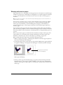
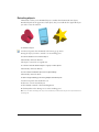
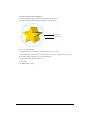
Macromedia FreeHand MX is a vector-based drawing application. With FreeHand, you can
create vector graphics that can be scaled and printed at any resolution, without losing detail
or clarity.
You can use FreeHand to create print and web illustrations such as logos and advertising banners.
You can also use FreeHand to turn your artwork into Macromedia Flash animations.
The FreeHand user interface contains a workspace and Tools panel that are consistent with other
Macromedia products such as Macromedia Dreamweaver, Fireworks, and Flash, to give you a
true integrated print and web solution. In addition, now you can view and test your FreeHand
documents in a Macromedia Flash Player window without ever leaving the FreeHand
environment.
System requirements
FreeHand runs on both Microsoft Windows and Macintosh operating systems. Their installers
are found on separate CDs. To install FreeHand and begin using the application, you will need
the following hardware and software:
• For Windows: An Intel Pentium II processor (300 MHz or faster), or the equivalent, running
Windows 98SE, Windows ME, Windows 2000, Windows NT version 4 (Service Pack 6), or
Windows XP; enough random-access memory (RAM) to meet your operating system’s
requirements, plus 64 MB of application memory (128 MB recommended); 70 MB of
available hard disk space; a CD-ROM drive; a color monitor capable of 1024 x 768 pixel
resolution and 16-bit display (thousands of colors, millions of colors recommended); Adobe
Type Manager version 4 or later with Type 1 fonts; and a PostScript Level 2–compatible
printer or later (recommended).
• For the Macintosh: a Power Macintosh G3 (or faster) computer running Mac OS 9.1 or later,
or Mac OS 10.1 or later; enough RAM to meet your operating system’s requirements, plus 64
MB of application memory; 70 MB of available hard disk space; a CD-ROM drive; a color
monitor capable of 1024 x 768 pixel resolution and 16-bit display (thousands of colors,
millions of colors recommended); Adobe Type Manager version 4 or later with Type 1 fonts
(Mac OS 9.x); a PostScript Level 2–compatible printer or later (recommended); and
QuickTime 6 (Mac OS 9.x).
7
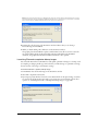
Installing and starting FreeHand
This section describes how to install FreeHand on your hard disk and start the application.
Before you begin, make sure your computer meets the requirements listed under “System
requirements” on page 7. Read the Read Me document on the FreeHand CD for late-breaking
information.
To install and start FreeHand in Windows:
1
Disable any virus-protection software.
2
Insert the FreeHand CD into the computer’s CD-ROM drive.
3
Follow the onscreen instructions. The FreeHand installer prompts you to enter the serial
number found on your registration card.
4
Select Start > Programs > Macromedia FreeHand MX > FreeHand MX to launch FreeHand.
To install and start FreeHand on the Macintosh:
1
Insert the FreeHand CD into the computer’s CD-ROM drive.
2
From the Apple menu, select Control Panels > Extensions Manager.
3
Disable virus-protection extensions and restart your computer.
The CD folder appears on your desktop.
4
Open the FreeHand MX folder.
5
Double-click the FreeHand MX Installer icon to launch the FreeHand installer.
6
Follow the onscreen instructions. The FreeHand installer prompts you to enter the serial
number found on your registration card.
When the installation is complete, the FreeHand folder opens on your desktop.
7
If prompted, restart your computer.
Uninstalling FreeHand
To uninstall FreeHand, you use Add/Remove Programs (Windows) or the installer (Macintosh)
to ensure that all FreeHand files are removed from your system.
To uninstall FreeHand in Windows:
1
Select Start > Settings > Control Panel.
2
Double-click Add/Remove Programs.
3
Select Macromedia FreeHand MX from the list of programs that can be removed.
4
Click the Add/Remove button.
5
Follow the onscreen instructions.
All FreeHand MX program files are removed from your system.
8
Introduction
To uninstall FreeHand on the Macintosh:
1
Insert the FreeHand CD into the computer’s CD-ROM drive and launch the installer.
2
A pop-up menu prompts you to select an option. Select Uninstall.
3
Follow the onscreen instructions.
Note: If you used custom installation to install FreeHand in a folder other than the default folder, you must specify
the same folder when uninstalling.
The installer removes all FreeHand application files from your computer.
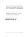
Resources for learning FreeHand
FreeHand MX includes a variety of media to help you learn the program quickly and become
proficient in creating your own FreeHand illustrations. These resources include Using FreeHand, a
user’s guide that comes in two formats: the help system, and in book form as a PDF file on the
application CD.
In addition, Macromedia presents helpful information via the Answers panel. The Answers panel
gives you easy access to the latest information on the Macromedia website. On the website, the
FreeHand Support Center (www.macromedia.com/support/freehand) offers support and
problem-solving information. The Designer & Developer Center (www.macromedia.com/
desdev) presents information to help you improve your skills and learn new ones.
FreeHand lessons
If you are new to FreeHand, or if you have used only some of its features, start with the lessons.
The lessons introduce you to the main features of FreeHand, letting you practice on isolated
examples.
To view the lessons:
1
With a working Internet connection, do one of the following:
• Select Help > Learning FreeHand.
• Select Window > Answers. In the Answers panel, select the Tutorials link.
A browser window displays the “Learning FreeHand MX” web page.
2
Select one of the lessons in the list.
FreeHand tutorial
The FreeHand tutorial presents a hands-on introduction to the FreeHand workflow by leading
you through the creation of a FreeHand illustration. Included in the tutorial are steps involving
many features that are new to FreeHand MX. The tutorial assumes that you already understand
the topics covered in the FreeHand lessons.
To view the tutorial:
1
With a working Internet connection, do one of the following:
• Select Help > Learning FreeHand.
• Select Window > Answers. In the Answers panel, select the Tutorials link.
A browser window displays the “Learning FreeHand MX” web page.
2
Select the link to the tutorial.
Getting Started
9
What’s new in FreeHand MX
Whether you design illustrations for print media, the web, or a combination of both, FreeHand
MX offers new features that enhance the approachability, creativity, and power of FreeHand.
Standards and interactivity
FreeHand MX has a new user interface that simplifies workflow and organizes the workspace
better. The new interface makes FreeHand easier to learn if you already know other Macromedia
Studio MX products, including Dreamweaver MX, Flash MX, and Fireworks MX.
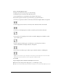
Panel grouping/tabs Panels are now conveniently docked together at the right edge of the
application window. You can move, separate, or combine these customizable panel groups. For
more information, see “Using panels” on page 15.
Object panel The Object panel is a context-sensitive panel that lets you view and change
properties for selected objects and text. It is extremely useful in performing practically any
drawing task. For more information, see “Using the Object panel” on page 107.
FreeHand can now launch Flash to edit imported Flash movies.
For more information, see “Editing imported Flash movies” on page 336.
Launching and editing Flash
Launching and editing Fireworks When you’re editing a bitmap file, FreeHand can
automatically launch Macromedia Fireworks, letting you use Fireworks bitmap editing tools to
modify the image or to make quick optimization changes. Together, the two applications give you
a more streamlined workflow for editing and designing graphics. For more information, see
“Launching Fireworks to edit imported bitmap images” on page 320 and “Launching Fireworks
to optimize bitmap images” on page 321.
Answers panel The Answers panel helps you work more effectively by giving you quick access
to Macromedia website content such as tutorials, lessons, TechNotes, and other useful
information. To learn more, see “The Answers panel” on page 21.
Power illustration
Many new features make FreeHand MX an even more powerful illustration tool.
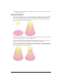
Extrude tool The new Extrude tool lets you apply 3D extrusion effects to an object. To learn
more, see “Extruding objects” on page 205.
With FreeHand MX, you can now apply more than one stroke or fill
to an object, opening up fascinating new potentials for your illustrations. See “Adding strokes and
fills to objects” on page 165.
Multiple strokes and fills
Live raster effects work similarly to some of the image
manipulation tools found in photo editing software such as Fireworks. These effects act as
properties of the object they are applied to, and do not modify the object itself. For more
information, see “Applying live raster effects” on page 198.
Live raster effects and transparency
Transparency effects allow a fill or stroke (or parts of a fill or stoke) to appear clear or semiopaque. To learn more, see “Using a Transparency effect attribute” on page 204.
Live vector effects Live vector effects work similarly to some of the other object manipulation
capabilities of FreeHand, except that they act as properties of the object they are applied to,
and do not modify the object itself. For more information, see “Applying live vector effects” on
page 194.
10
Introduction
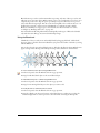
Blend tool Blends are now easier to apply. The Blend tool lets you drag a line between two
blend shapes to create the blend. See “Using the Blend tool” on page 213.
This new feature lets you create beautiful calligraphic strokes as part of your
vector objects. For more information, see “Using calligraphic stroke attributes” on page 173.
Calligraphic stroke
Eraser tool The new Eraser tool lets you erase parts of vector objects. To learn more, see
“Erasing paths” on page 95.
FreeHand MX provides full import and display support for the alpha
channels of common bitmap image files. See “Working with bitmap images in FreeHand” on
page 318.
Image alpha channels
Two new gradient fills have been added to FreeHand MX: rectangular and
cone gradients. Also, gradient fills now have new options. For more information, see “Using
gradient fill attributes” on page 179.
New gradient fills
The Rounded Corners attribute gives brushed paths a more fluid and
natural look as they wrap around corners and sharp angles. To learn about brushes, see “Using
brush stroke attributes” on page 169.
Brush enhancements
Web-related features
Many new and enhanced FreeHand MX features help you plan, mock up, and develop website
components. With these additions, FreeHand MX becomes the tool of choice for the beginning
stages of web development, and the first step in the Macromedia Studio MX workflow.
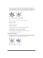
The Connector tool lets you draw connector lines that dynamically link objects
together. Connector lines automatically adjust when you move connected objects in the
Document window. For more information on the Connector tool, see “Dynamically linking
objects” on page 102.
Connector tool
The Action tool lets you assign Flash actions to an object. For more information, see
“Using the Action tool” on page 334.
Action tool
You can now print or export an area of the Document window by using the
Output Area tool. To learn more, see “Exporting an area of a document” on page 348.
Output area
It’s now easier to control the settings of a Flash movie inside
FreeHand. For more information, see “Using Flash movies” on page 335.
Simplified movie settings
Flash SWF files can be directly imported and placed in
FreeHand MX, and then exported. See “Editing imported Flash movies” on page 336 and
“Exporting FreeHand documents as Flash movies” on page 336.
SWF import, placement, and export
Getting Started
11
Ease of use
Finally, many new FreeHand MX features are dedicated to making your workflow easier than ever.
The Tools panel has been reorganized to make finding and using your
tools easier. To find out more, see “Using the Tools panel” on page 24.
Tools panel changes
Gradient fill handles increase your control in manipulating gradient fills.
See “Using gradient fill attributes” on page 179.
Gradient fill handles
Adding a new page to your document is now as easy as clicking the Add Page
button at the bottom of the application window. See “Working with pages” on page 44.
Add page button
You can control what types of object attributes a style will apply to. See
“Applying styles” on page 302.
Style behavior changes
12
Introduction
CHAPTER 1
FreeHand Basics
To get the most out of working in Macromedia FreeHand MX, it’s helpful to familiarize yourself
with the FreeHand workspace, which includes the Document window, command menus at the
top of your screen, tools and panels for editing and adding objects, and the pasteboard in which
you create your artwork.
You can add more commands to the menus by installing software applications called plug-ins, and
you can add and rearrange tools in toolbars by customizing your work environment.
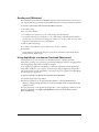
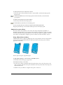
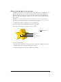
About vector graphics and bitmap images
FreeHand is a vector-graphic drawing application. A vector-graphic image is resolutionindependent—it can be scaled to any size and printed on any output device at any resolution,
without losing detail or clarity. In contrast, bitmap graphics—commonly used in image-editing
applications—are composed of pixels. Their display depends on the resolution of the monitor
or printer. Bitmap graphics can appear jagged and lose detail when they’re scaled onscreen or
printed at a low resolution. For more details on vector graphics, see “About vector graphics” on
page 69.
Although vector graphics always appear at your computer’s maximum screen resolution, you can
specify a lower resolution for preparing draft documents. For more information, see Chapter 14,
“Printing,” on page 375.
13
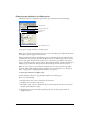
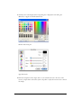
The Macromedia Studio MX interface
FreeHand is part of the Macromedia MX product family, so it utilizes the Macromedia MX
workspace, an interface that is shared by the other Macromedia MX products. Consistency
among products allows users of one product to easily learn and use the others.
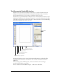
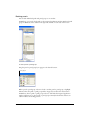
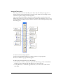
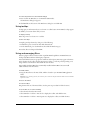
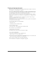
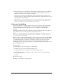
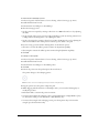
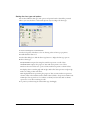
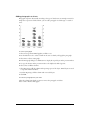
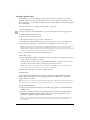
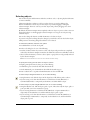
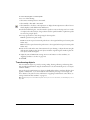
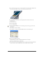
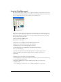
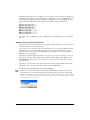
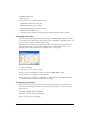
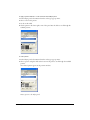
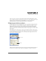
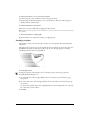
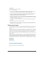
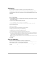
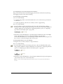
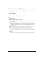
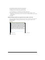
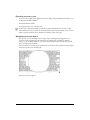
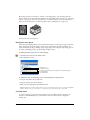
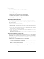
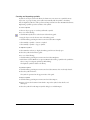
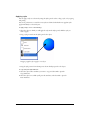
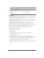
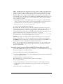
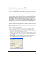
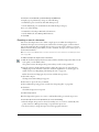
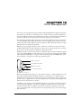
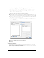
The first time you open FreeHand, the workspace consists of the Document window and a set of
docked panels. In Windows, the workspace is integrated, so you can dock all panels and toolbars
to the single, larger application window. This helps to eliminate the clutter associated with having
many panels and toolbars open at the same time.
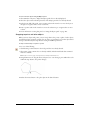
Panels
Units pop-up menu
Drawing Mode pop-up menu
Add Page button
Go to Page pop-up menu
Page selector buttons
Magnification pop-up menu
The integrated workspace is not supported on the Macintosh. However, panels and toolbars
are docked together by default in a configuration that resembles the integrated workspace
in Windows.
On all operating systems, FreeHand panels, toolbars, and windows can be rearranged,
repositioned, and docked to one another.
For more details about the FreeHand workspace, see the sections that follow.
14
Chapter 1
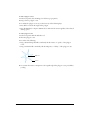
The Document window
In addition to panels, when you launch FreeHand you’ll also see the Document window and the
pasteboard—the area that contains the pages of your document.
The Document window contains all your documents’ objects. Objects must be placed on a page
in order to be printed with the Print command; if they are placed on the pasteboard outside of
page boundaries, you can print them using the Output Area feature. For more information, see
“Defining an output area” on page 382.
The pasteboard measures up to 222 x 222 inches and can hold 520 letter-sized pages. You can
customize the buttons, panels, and toolbars. For more information on panels and toolbars, see
“Using panels” on page 15 and “Customizing toolbars” on page 38.
If you modify a document, an asterisk appears next to the document name in the Document
window until you save it again. For more information, see “Saving files” on page 341.
Using panels
When you first launch FreeHand, visible panels (excluding the Tools panel) are docked together
at the right edge of the application window. You can move, separate, or combine these
customizable panel groups. Panels and panel groups can be opened, closed, docked, expanded,
and collapsed.
The following panels are grouped together by default:
• The Object and Document panels reside in a panel group called Properties.
•
•
•
•
The Swatches, Styles, and Library panels reside in a panel group called Assets.
The Color Mixer and Tints panels reside in a panel group called Mixer and Tints.
The Align and Transform panels reside in a panel group called Align and Transform.
The Find & Replace panel and the Select panel reside in a panel group called Find & Replace
and Select.
FreeHand Basics
15
• The Halftones, Layers, Answers, and Navigation panels are not grouped with other panels by
default, but you can group them if you want. With the exception of the Properties and Assets
panel groups, when you group panels together, all panel group names appear in the panel
group title bar. You can, however, name panel groups anything you like; see “Grouping panels”
on page 19.
The Layers panel, the Answers panel, and the Properties, Assets, and Mixer and Tints panel
groups appear onscreen by default when you first open FreeHand, although some may be
collapsed.
To open a panel:
Select its name from the Window menu.
If a panel was already open, choosing its name from the Window menu closes it or collapses it,
depending on whether the panel is docked.
Note: The Find & Replace and Select panels are available in the Edit menu.
To expand or collapse a panel:
Click the panel group name or the expander arrow beside it.
Tip: If a panel is open but collapsed, you can select the panel’s name from the Window menu to expand it.
To close a panel:
Click the Close button at the top of a floating panel or floating panel group.
To activate a panel in a panel group:
Click the panel’s name or icon.
To move an undocked panel or panel group to another location:
Drag the panel group by its title bar (the area above the panel group name).
Tip: Be careful not to drag a panel group’s gripper, or you might inadvertently dock it to another panel group.
To switch between open, floating panel groups (Windows):
Press Control+Tab.
To show or hide all open panels:
Select View > Panels.
16
Chapter 1
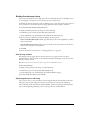
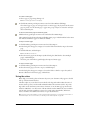
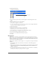
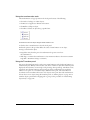
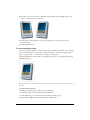
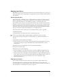
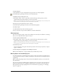
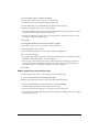
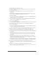
To show or hide panels docked to the application window (Windows only):
Click the small arrow that separates the docked panel area from the rest of the application
window.
Click to show or hide docked panel area
To return panels to their default positions:
1
Exit FreeHand.
2
Locate the Macromedia/FreeHand/11/English/Settings folder within your user-specific
Application Data (Windows) or Application Support (Macintosh) folder.
Note: The exact location of your user-specific Application Data or Application Support folder varies depending
on your operating system. For more information, see your operating system’s documentation.
3
Delete the fhprefs.txt (Windows) or Preferences (Macintosh) file.
To define the appearance of panel labels:
1
Display panels preferences by doing one of the following:
• In Windows, press Control+U, then click the Panels tab.
• On the Macintosh, press Command+U, then click the Panels category.
2
From the Label Panel Tabs With pop-up menu, choose to label panels with text only, icon only,
or a text and icon combination.
3
Click OK.
FreeHand Basics
17
Docking panels
You can dock individual panels and panel groups to one another.
In Windows, you can also dock panels to the integrated application window. Panels and panel
groups in Windows can be docked on the right side, left side, or both sides of the screen.
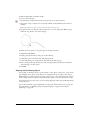
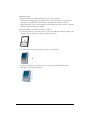
To dock a panel or panel group:
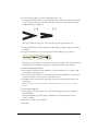
Drag the panel or panel group by its gripper to the desired location.
Panel gripper
When a panel or panel group is about to dock to another panel or panel group, a highlight
indicates where the panel or panel group will be dropped if you release the mouse button.
In Windows, when a panel or panel group is about to dock with the integrated application
window and there are no other panels or panel groups currently docked in that location, an
outline indicates the docking position.
18
Chapter 1
To undock a panel or panel group:
Drag the panel or panel group by its gripper to the desired location.
Using a panel’s Options menu
Each panel has an Options menu listing a range of choices specific to the active panel.
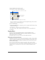
To open a panel’s Options menu:
Click the Options menu control in the upper right corner of the panel group.
Options menu control
Grouping panels
You can group panels with other panels, add them to existing panel groups, or remove them from
panel groups.
When you combine panels into a group, the panel group title reflects the names of each of the
panels. If a panel group title becomes too long, you can rename it.
To group panels:
1
Open or expand the panel that you want to add to a group.
2
Select Group [Panel Name] With from the panel’s Options menu, and select a panel or panel
group from the pop-up menu.
FreeHand Basics
19
To remove a panel from a group:
1
Activate the panel you want to remove from the group.
2
Select Group [Panel Name] With from the panel’s Options menu, and select New Panel
Group.
The panel becomes its own panel group.
To rename a panel group:
1
With any panel active in the panel group, select Rename Panel Group from the panel’s Options
menu.
2
Type a new name.
3
Click anywhere outside the panel group, or press Enter (Windows) or Return (Macintosh).
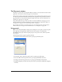
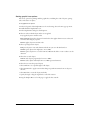
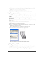
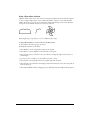
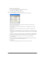
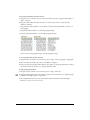
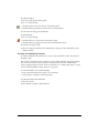
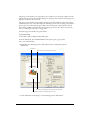
The Properties panel group
The Properties panel group contains two panels that allow you to display and alter the properties
of objects and pages.
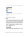
The Object panel displays properties for a selected object or objects. The top half of the panel
displays a list of properties, such as stroke, fill, and effect, applied to a selected object. The bottom
half of the panel is context-sensitive; it displays options for the selected property in the
list above it.
The Object panel is used in almost all drawing tasks. For more information about the Object
panel, see “Using the Object panel” on page 107; “Applying attributes to strokes” on page 166;
“Applying attributes to fills” on page 177; “Displaying type attributes in the Object panel” on
page 248; and Chapter 7, “Special Effects,” on page 193.
20
Chapter 1
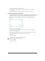
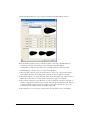
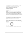
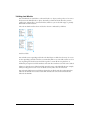
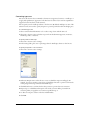
The Document panel displays thumbnail icons for each page in your document. Using the
Pointer tool, you can move the thumbnails in the panel to move the corresponding pages on the
pasteboard. You can choose from three magnified views. The Document panel also has options
for adding, duplicating, and removing pages, plus options to set page size, orientation, bleed, and
printer resolution. For more information, see “Using the Document panel” on page 43.
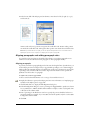
The Answers panel
The Answers panel helps you work more effectively in FreeHand by providing quick access to
Macromedia website content such as tutorials, TechNotes, and other useful information.
To get the latest FreeHand information from macromedia.com, with an active Internet
connection, click the Update button.
FreeHand Basics
21
Using toolbars
FreeHand has several toolbars that can either float or be docked along the top, left, and bottom of
the Document window. You can customize toolbars; for more information, see “Customizing
toolbars” on page 38.
You can display information about each tool as the pointer passes over it (see “Using tooltips” on
page 27).
FreeHand has the following toolbars:
• The Tools panel is actually a toolbar. Like other toolbars, it can be docked to the top or bottom
of the application window. For more information, see “Using the Tools panel” on page 24.
• The Main toolbar replicates many of the menu commands and lets you create, open, or save
documents; import files; find and replace graphics; lock and unlock objects; and display
commonly used panels. For more information, see “The Main toolbar” on page 23.
• The Text toolbar contains common text commands and lets you choose a font, font size, font
style, leading, and alignment as well as other text-related functions. For more information, see
“The Text toolbar” on page 249.
• The Envelope toolbar has tools for applying envelope transformations to objects or groups. For
more information, see “Creating perspective” on page 227.
• The Info toolbar gives information on selected objects, depending on the object type and
current action. Possible items included in this toolbar are the object type, the pointer position,
the change in an object’s position, the object’s angle, the center of rotation, the radius, and the
number of sides the object has.
• The Status toolbar (Windows) appears along the bottom of the Document window. For more
information, see “The Status toolbar” on page 25.
• The Xtra Tools toolbar contains plug-in drawing and transformation tools, which can be
added and removed from the application. For more information, see “Using and managing
Xtras” on page 27.
• The Xtra Operations toolbar contains buttons for applying path operations. For more
information, see “Combining paths” on page 127.
To dock and undock toolbars:
Drag the toolbar to the desired location.
An outline appears indicating where the toolbar will be dropped if you release the mouse button.
To show or hide toolbars, do one of the following:
• To show or hide individual toolbars, select Window > Toolbars and select the toolbar name.
• To show or hide all active toolbars, select View > Toolbars.
• To show or hide the Tools panel, select Window > Tools.
22
Chapter 1
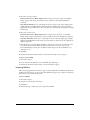
The Main toolbar
The Main toolbar contains the basic commands you use when beginning your FreeHand project.
You use the Main toolbar to open document files and to manage the appearance of your
document. The Main toolbar also provides quick access to many common panels. The following
buttons are available on the Main toolbar by default, but you can add other buttons if you want.
For more information, see “Customizing toolbars” on page 38.
Creates a new document
Opens the Align panel
Opens an existing document
Opens the Transform panel
Saves the active document
Opens the Library panel
Imports a file or object
Opens the Object panel
Prints the active document
Opens the Color Mixer panel
Locks the selected objects
Opens the Swatches panel
Unlocks the selected objects
Opens the Layers panel
Opens the Find & Replace panel
FreeHand Basics
23
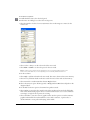
Using the Tools panel
The Tools panel contains tools that allow you to select, draw, and edit objects; apply color to
objects; and create text. It is divided into four sections: Tools, View, Colors, and Snap. You can
customize the panel by adding and removing buttons.
Some tools in the Tools panel have a down arrow in the lower right corner. The down arrow
indicates the presence of a tool pop-up menu. You can select the other members of a tool pop-up
menu by clicking and holding on any tool that has a down arrow, then selecting from the pop-up
menu that appears.
To select a tool from a tool pop-up menu:
1
In the Tools panel, click and hold on a tool that is part of a tool pop-up menu.
2
Select a tool from the pop-up menu that appears.
To add a tool to the Tools panel, do one of the following:
• Select Window > Toolbars > Customize. Expand the desired category in the Commands list,
and drag a tool from the right side of the dialog box into the Tools panel.
• Alt-drag (Windows) or Command-drag (Macintosh) a tool from another toolbar into the
Tools panel.
24
Chapter 1
To remove a tool from the Tools panel, do one of the following:
• Select Window > Toolbars > Customize, and drag the desired button from the Tools panel.
• Alt-drag (Windows) or Command-drag (Macintosh) a tool from the Tools panel.
Once you remove a tool from the Tools panel, you cannot move the tool back onto the panel
without using the Customize dialog box. For more information on customizing toolbars, see
“Customizing toolbars” on page 38.
The Status toolbar
The Status toolbar appears along the bottom of the Document window. It contains a page
addition button and page selector buttons as well as pop-up menus for magnification, page view,
drawing mode, and units of measure.
In Windows, the Status toolbar displays messages about the task in progress or the menu
command highlighted. To cancel an operation in progress in Windows, you can click the toolbar’s
Cancel button.
On the Macintosh, the Status toolbar is permanently docked to the Document window; you can’t
undock it or move it to another location.
Using preferences
FreeHand preferences let you customize your work environment. Settings stored in the
Preferences file include the following:
•
•
•
•
•
•
•
•
•
Number of undo operations
•
•
•
•
Spelling preferences
Path-editing behavior, path fills, and path behavior
Default line widths and graphic styles
Text behavior
Document views and window location
Active page settings
Settings for reviewing documents when closing them
Attributes of imported and exported files
Settings for embedding graphics in Encapsulated PostScript (EPS) and other Clipboard
formats
Guide and grid colors and color management options
Panel display options
Text effects, small text size (“greeked” type), image screen resolution, and objects set to
overprint
• Snap sounds (Macintosh only)
FreeHand Basics
25
To find an explanation of a particular preference option or set of options, refer to the index.
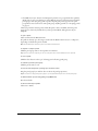
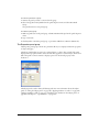
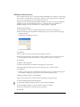
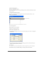
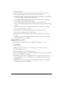
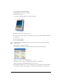
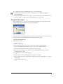
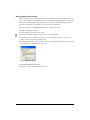
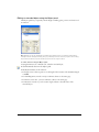
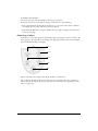
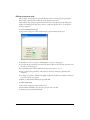
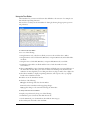
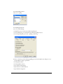
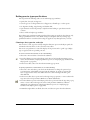
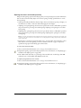
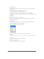
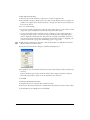
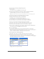
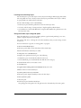
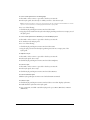
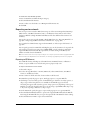
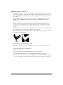
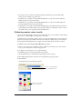
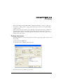
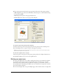
To display preference options:
1
Press Control+U (Windows) or Command+U (Macintosh).
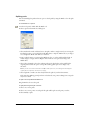
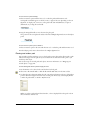
2
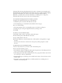
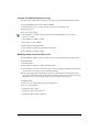
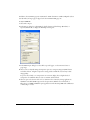
In Windows, click a tab; on the Macintosh, click an item in the Category list.
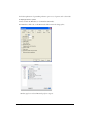
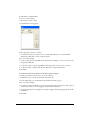
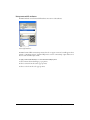
Windows preference tabs and Macintosh preference categories
26
Chapter 1
To restore all preferences to their default settings:
1
Press Control+U (Windows) or Command+U (Macintosh).
The Preferences dialog box appears.
2
Click Defaults at the bottom of the Preferences dialog box, and click OK.
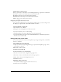
Using tooltips
Tooltips give you information about a tool name or toolbar button. In FreeHand, tooltips appear
by default; you can turn them off if you want.
To display a tooltip:
Pause the pointer over a button on a toolbar.
To turn off tooltips:
1
Display panels preferences by doing one of the following:
• In Windows, press Control+U, then click the Panels tab.
• On the Macintosh, press Command+U, then click the Panels category.
2
Deselect Show ToolTips and click OK.
Using and managing Xtras
Xtras are plug-in software extensions that expand FreeHand capabilities. FreeHand Xtras are
developed by Macromedia and third-party companies.
Xtras with similar features are grouped in submenus. A third-party Xtra may appear in the Xtras
menu, the Xtra Tools toolbar, the Xtra Operations toolbar, or a custom panel, depending on its
design and the customizations made within the user interface.
Xtras included with FreeHand are automatically installed with FreeHand. You can install
additional Xtras and remove Xtras.
To install an Xtra:
1
Drag the Xtra file into the Xtras folder, which is located in your FreeHand MX application
folder.
Note: On some operating systems, this folder may be located in the English subfolder within the FreeHand MX
application folder.
2
Restart FreeHand.
To remove an Xtra:
Drag the Xtra file out of the Xtras folder. (See the previous procedure for folder location.)
To use an Xtra, do one of the following:
• Select the Xtra from the Xtras menu.
• Select Window > Toolbars > Xtra Tools to display the toolbar, and click the Xtra.
• Select Window > Toolbars > Xtra Operations to display the toolbar, and click the Xtra.
FreeHand Basics
27
Setting the document view
You can set your document view to help you work more efficiently. You can use multiple views to
see several pages or documents at once, and you can create custom views.
Commands in the View menu let you choose different ways to view and preview your work. You
can set preferences to determine the view and page placement when opening a document.
To set document view and placement preferences:
1
Display document preferences by doing one of the following:
• In Windows, press Control+U, then click the Document tab.
• On the Macintosh, press Command+U, then click the Document category.
2
Select an option to define how documents will appear when opened:
Restore View When Opening Document
opens documents at the same magnification as when
they were last saved.
opens documents in the same window size and at the
same location as the last saved document.
Remember Window Size and Location
3
Click OK.
For more information on preferences, see “Using preferences” on page 25.
Anti-aliasing artwork
Anti-aliasing removes jagged edges in onscreen artwork, so it appears smooth even when
magnified. Vector objects and text are anti-aliased by default in all drawing modes. You can turn
this option off if you want.
Note: On the Macintosh, anti-aliasing is available only if you’re running Mac OS X or later.
To turn off anti-aliasing:
1
Display redraw preferences by doing one of the following:
• In Windows, press Control+U, then click the Redraw tab.
• On the Macintosh, press Command+U, then click the Redraw category.
2
Deselect Enable Anti-Aliasing and click OK.
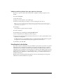
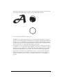
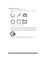
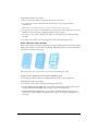
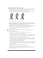
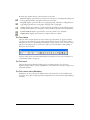
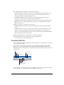
Optimizing document redrawing
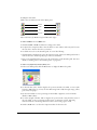
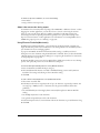
You can choose how to view a document onscreen using drawing modes. Drawing modes don’t
affect object data or print quality. You can also set preferences to control screen redrawing.
The fast drawing modes, Fast Preview and Fast Keyline, optimize redrawing by reducing blend
steps to 10 and greeking (dimming) text for onscreen point sizes of 50 and below.
28
Chapter 1
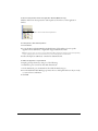
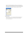
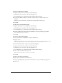
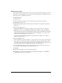
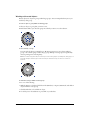
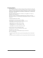
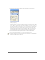
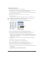
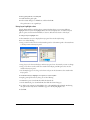
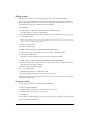
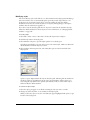
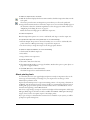
To choose a drawing mode:
Select an option from the Drawing Mode pop-up menu in the Status toolbar (Windows) or at the
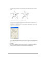
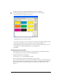
bottom of the Document window (Macintosh):
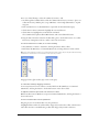
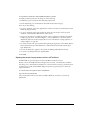
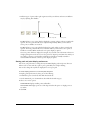
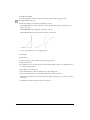
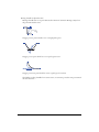
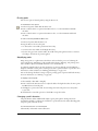
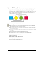
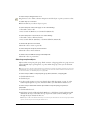
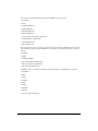
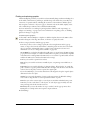
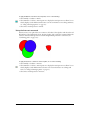
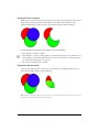
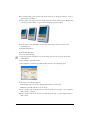
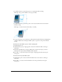
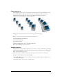
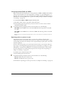
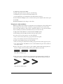
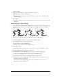
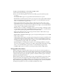
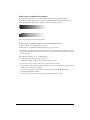
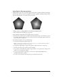
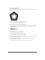
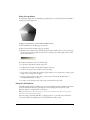
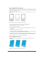
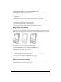
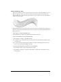
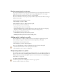
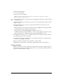
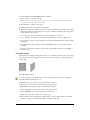
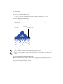
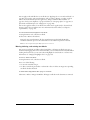
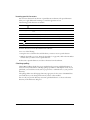
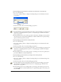
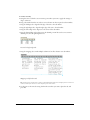
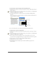
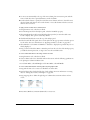
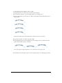
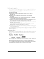
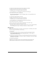
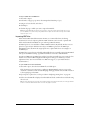
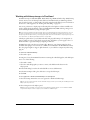
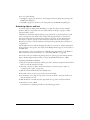
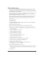
Preview displays the document as it will print. (You can’t preview custom, PostScript, or textured
strokes and fills.)
Fast Preview
displays blends with reduced steps and greeked (dimmed) text.
Keyline displays only a black hairline stroke, no fill for objects, and X-boxes for EPS images and
bitmap images.
Fast Keyline
displays blends with reduced steps and greeked (dimmed) text.
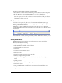
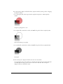
From left to right: Preview, Fast Preview, Keyline, Fast Keyline
To switch between Preview mode and Keyline mode:
Select View > Keyline.
This command is a toggle. A checkmark beside Keyline indicates that the document is in one of
the Keyline modes. When no checkmark is displayed, the document is in one of the Preview
modes.
To switch between fast modes and other modes:
Select View > Fast Mode or press Control+Shift+K (Windows) or Command+Shift+K
(Macintosh).
These commands toggle between fast modes and other modes. A checkmark beside Fast Mode
indicates the document is either in Fast Preview or Fast Keyline mode.
FreeHand Basics
29
To set how scrolling affects redrawing:
1
Display redraw preferences by doing one of the following:
• In Windows, press Control+U, then click the Redraw tab.
• On the Macintosh, press Command+U, then click the Redraw category.
2
Select Redraw While Scrolling to redraw the document when you click a scroll arrow or
scroll bar.
When this option is deselected, the document is redrawn when scrolling stops.
3
Click OK.
To enable object previews while dragging:
1
Display object preferences by doing one of the following:
• In Windows, press Control+U, then click the Object tab.
• On the Macintosh, press Command+U, then click the Object category.
2
Deselect the Alt-Drag Copies Paths option (Windows) or the Option-Drag Copies Paths
option (Macintosh), if it is selected.
3
Click OK.
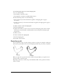
To preview an object while dragging it:
1
Press and hold down Alt (Windows) or Option (Macintosh).
2
Drag the object.
Note: Before dragging the object, ensure that the Alt-Drag Copies Paths option (Windows) or the Option-Drag
Copies Paths option (Macintosh) is deselected in object preferences. See the previous procedure.
To set the maximum number of objects to preview while dragging:
1
Display redraw preferences by doing one of the following:
• In Windows, press Control+U, then click the Redraw tab.
• On the Macintosh, press Command+U, then click the Redraw category.
2
Enter a value in the Preview Drag text box.
Note: Previewing a large number of objects can slow redrawing.
3
Click OK.
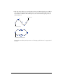
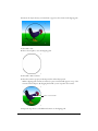
To drag an object without previewing it:
Drag the object within the Document window.
The object’s path displays the object’s movement, similar to the way in which objects appear in
Keyline mode.
30
Chapter 1
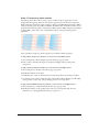
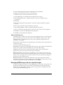
Magnifying and reducing the view
You can zoom in or out to magnify or reduce your view using tools, menu commands, or
keyboard shortcuts. Using the Zoom tool, you can create custom views based on the applied
magnification. Using the View menu or the document’s Magnification pop-up menu, you can
select magnifications ranging from 6% to 6400%, depending on the menu you use.
In Windows, you can use the right mouse button to magnify a selected area. You specify this
behavior through preferences; see “Using the right mouse button (Windows)” on page 33.
To enlarge or reduce a page view using the Zoom tool:
1
Click the Zoom tool.
2
Do one of the following:
•
•
•
•
To enlarge the page, click the page.
To enlarge a selected area, drag the selection.
To reduce the page view, hold down Alt (Windows) or Option (Macintosh) and click the page.
To reduce a selected area, Alt-drag (Windows) or Option-drag (Macintosh) the selection.
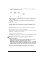
To enlarge or reduce a page using menu commands, do one of the following:
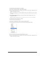
• Select an increment from the Magnification pop-up menu in the Status toolbar (Windows) or
at the bottom of the Document window (Macintosh), or enter a value into the text box. You
can also enter a value followed by x, up to 256x.
Magnification pop-up menu
• Select View > Magnification to select an increment from 25% to 800%.
• In Windows, right-click in the workspace to display a context menu, then select View and
select an increment between 6% and 6400%.
To enlarge or reduce a page using keyboard shortcuts:
1
Click the Zoom tool.
2
Do one of the following:
• To reduce the page view to the next increment, hold down Alt (Windows) or Option
(Macintosh) and click the page.
• To zoom out to the lowest magnification, hold down Shift+Alt (Windows) or Control+Option
(Macintosh) and click the page.
• To zoom in to the highest magnification, hold down Shift (Windows) or Control (Macintosh)
and click the page.
FreeHand Basics
31
To fit the view to a selection or page:
Select an option from the View menu, or from the Magnification pop-up menu in the Status bar
(Windows) or at the bottom of the Document window (Macintosh):
Fit to Page
fits the active page inside the Document window.
Fit Selection
Fit All
fits all selected objects inside the Document window.
fits all pages inside the Document window.
Displaying multiple document views
To see a document at different views or magnifications simultaneously, you can use multiple views
and display up to eight windows of the same document at one time.
To open an additional document view:
1
Select Window > New Window.
2
Change the view and magnification of the new window.
To close document views, do one of the following:
• Click the window’s Close button (Windows) or close box (Macintosh).
• To close all document views, press Control+Shift+F4 (Windows) or hold down Option and
click the close box (Macintosh).
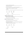
Naming and saving custom views
You can name and save the current view’s magnification percentage, drawing mode, and scroll bar
positions to recall later.
To save settings with a custom view name:
1
Adjust view elements using the Magnification pop-up menu, Drawing Mode pop-up menu,
and scroll bars, as desired.
2
Select View > Custom > New.
3
Name the view and click OK.
To recall a saved view, do one of the following:
• Select the view name from the Magnification pop-up menu.
• Select View > Custom, and select the view from the pop-up menu.
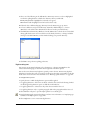
To define, name, and save a view using the Zoom tool:
1
Click the Zoom tool.
2
Shift-drag to define the new view.
The New View dialog box appears after the new view is set.
3
32
Name the new view and click OK.
Chapter 1
To edit a custom view:
1
Adjust view elements to redefine the view using the Magnification pop-up menu, Drawing
Mode pop-up menu, and scroll bars.
2
Select View > Custom > Edit.
3
In the Edit Views dialog box, select a custom view name and click Redefine.
Tip: To change the name of a custom view, double-click the custom view name and type a new name.
4
Click OK.
To delete a custom view:
1
Select View > Custom > Edit.
2
Select the view to be deleted.
3
Click Delete; then click OK.
To switch from the current to the previous view:
Select View > Custom > Previous.
Note: You can switch to the previous custom view only if you have created at least two custom views.
Using the right mouse button (Windows)
In Windows, you can choose commands from context menus as you work. By clicking the right
mouse button, you can display context-specific commands for panels and objects, including
paths, text blocks, bitmap images, EPS paths, groups, and blends.
You can also use the right mouse button to magnify an area of your document.
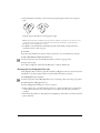
To display a context menu, do one of the following:
• Right-click an object to display a context menu with object-specific commands.
FreeHand Basics
33
• Select multiple objects by pressing Shift as you select the objects or by dragging a bounding
box around the objects. Right-click the selection to display common commands.
• Right-click a page, color box, style, or foreground or background layer.
This approach works in the Document panel, Swatches panel, Layers panel, Styles panel, and
Tints panel, as well as for any color swatch, color box, or blank area of the document.
To use the right mouse button to magnify an area of your document:
1
Display general preferences by doing one of the following:
• In Windows, press Control+U, then click the General tab.
• On the Macintosh, press Command+U, then click the General category.
2
Select Right Mouse Button Magnification, and click OK.
Note: Selecting this option disables Windows context menus.
34
Chapter 1
Printing a shortcut quick-reference card
You can print a shortcut quick-reference card and save a custom card.
To print a shortcut quick-reference card:
1
Select Edit > Keyboard Shortcuts.
2
In the Keyboard Shortcuts dialog box, click Print.
3
In the dialog box that appears, click Print again.
A system Print dialog box appears. Set any desired options and click the appropriate button to
send the card to your printer.
To save a custom keyboard shortcut card:
1
Select Edit > Keyboard Shortcuts.
2
In the Keyboard Shortcuts dialog box, click Print.
3
In the dialog box that appears, click Save As.
4
Navigate to a location to save the shortcut card, and enter a filename in the File Name text box.
5
Click Save.
FreeHand produces a text file that can be opened in another application (such as a word
processor), where you can format and reorder the text to create your own custom shortcut card.
For example, you might want to place the text in a table or sort it by shortcuts, commands, or
descriptions.
Customizing your environment
FreeHand lets you customize many aspects of its work environment. You can add and remove
keyboard shortcuts, use shortcuts from other applications, rearrange toolbars, and change toolbar
buttons.
Customizing shortcuts
To change current keyboard shortcuts or to assign shortcuts to commands that have no shortcuts,
you use the Shortcuts tab in the Customize dialog box (Windows) or the Customize Shortcuts
dialog box (Macintosh). Although you can assign shortcuts to the Repeat Xtra command, you
cannot assign shortcuts to other Xtras.
In addition to the default FreeHand shortcut group, FreeHand provides the default shortcut
groups for FreeHand 8, FreeHand 9, and many other applications, including Adobe Illustrator,
QuarkXPress, Adobe PageMaker (Macintosh), Adobe Photoshop (Macintosh), and Macromedia
Director (Macintosh). You can also copy custom shortcut groups from another user’s computer or
from another location on your hard disk.
FreeHand Basics
35
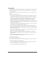
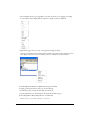
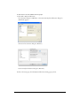
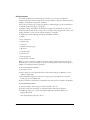
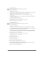
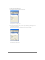
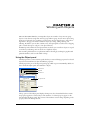
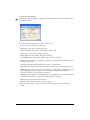
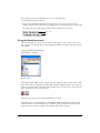
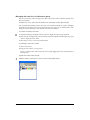
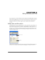
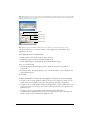
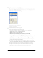
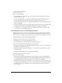
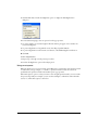
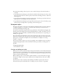
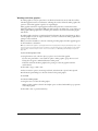
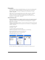
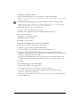
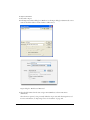
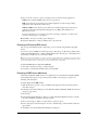
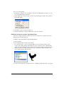
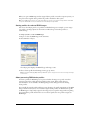
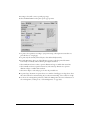
To view and choose from available shortcut groups:
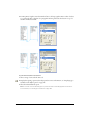
1
Select Edit > Keyboard Shortcuts.
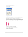
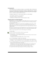
The Customize dialog box (Windows) or the Customize Keyboard Shortcuts dialog box
(Macintosh) appears.
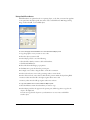
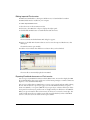
Shortcuts tab in Customize dialog box (Windows)
Customize Keyboard Shortcuts dialog box (Macintosh)
2
36
Select a shortcut group from the Keyboard Shortcuts Setting pop-up menu.
Chapter 1
To copy a customized shortcut group from one computer to another:
1
Select the Shortcuts file, located in the Keyboard folder within the Macromedia/FreeHand/11/
English/Settings folder in your user-specific Application Data (Windows) or Application
Support (Macintosh) folder.
Note: The location of your user-specific Application Data or Application Support folder varies depending on
your operating system. Refer to your operating system’s documentation for information on locating this folder.
2
Copy the file to the same location within a user folder on another computer.
The new group’s name appears in the Keyboard Shortcuts Setting pop-up menu. (Windows
adds the extension .set to the shortcut group file, but the extension does not appear in the
Keyboard Shortcuts Setting menu.)
To assign a custom shortcut:
1
Select Edit > Keyboard Shortcuts.
The Customize dialog box (Windows) or the Customize Keyboard Shortcuts dialog box
(Macintosh) appears.
2
Do one of the following to create a custom shortcut:
• Select an application from the Keyboard Shortcuts Setting menu.
• To keep all default FreeHand shortcuts intact and create your own shortcut group, click the
Plus (+) button under Keyboard Shortcuts Setting. Navigate to a location, name the file, and
click Save.
3
In the Commands list, click the plus (+) sign (Windows) or triangle (Macintosh) to expand the
categories.
The Commands list replicates all FreeHand menus, with some additional features. If the
command to which you want to assign a shortcut is not in a FreeHand menu, expand the
Tools/Commands category in the Commands list.
4
Click the name of the command to which you want to assign a new shortcut.
The command description appears under Description. The Current Shortcut Keys text box
displays any shortcuts already assigned to the command. A command can have more than one
shortcut, but only one appears in the menu.
5
Click in the Press New Shortcut Key text box, then press the key or keys that make up the new
shortcut sequence.
The new shortcut appears in the Press New Shortcut Key text box. Any shortcuts already
assigned to the command or keyboard sequence are listed under Currently Assigned To.
6
Select how to assign the shortcut:
• Select Go to Conflict on Assign to highlight in the Command list the command for a
previously assigned keyboard shortcut.
• Click Assign to assign the new shortcut to the specified command and disable any previous
assignment for the shortcut.
7
Repeat steps 4 through 6 to assign additional shortcuts.
8
Click Close to confirm the new shortcut assignments, or click Reset to revert to the previous
shortcuts without saving the new shortcuts.
FreeHand Basics
37
To remove a shortcut:
1
Select Edit > Keyboard Shortcuts.
2
Expand the Commands list to locate and select the desired command.
3
Select the shortcut you want to delete under Current Shortcut Keys.
4
Click Remove.
5
Click Close or select a new shortcut group to confirm the removal.
Customizing toolbars
To customize the form, location, and contents of a toolbar, you can use the Customize dialog box
(Windows) or the Customize Toolbars dialog box (Macintosh). You can also drag toolbar buttons.
Note: Disabled buttons cannot be moved or deleted.
38
Chapter 1
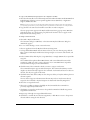
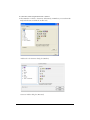
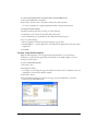
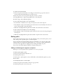
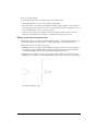
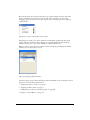
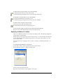
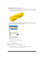
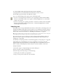
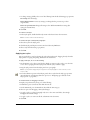
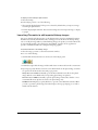
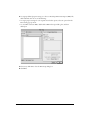
To customize toolbars using the Customize command:
1
Select Window > Toolbars > Customize. (Alternatively, in Windows you can select Edit >
Keyboard Shortcuts and click the Toolbars tab.)
Toolbars tab in the Customize dialog box (Windows)
Customize Toolbars dialog box (Macintosh)
FreeHand Basics
39
2
Do one of the following to select the command you want to add:
• Scroll through the Commands list to find the command whose button you want to place on a
toolbar. If necessary, click the plus (+) sign (Windows) or the triangle (Macintosh) to expand
categories.
• If the command is not in a FreeHand menu, expand the Tools/Commands category.
• Click a menu or menu command to highlight the associated buttons.
• Click a button to highlight the associated menu command.
The Commands list replicates all FreeHand menus, with some additional features.
3
Drag the button from the Customize Toolbars dialog box to the desired location on a toolbar.
If necessary, existing buttons move to make room for the new button.
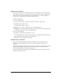
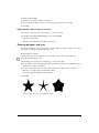
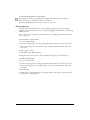
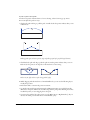
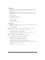
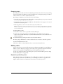
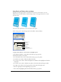
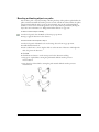
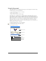
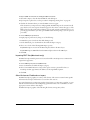
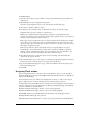
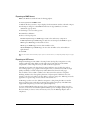
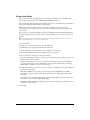
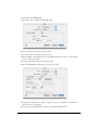
To remove a button from a toolbar, do one of the following:
• Select Window > Toolbars > Customize, and drag the button off the toolbar.
• Hold down Alt (Windows) or Command (Macintosh), and drag the button off the toolbar.
Note: You cannot undo this procedure once you drag the button off the toolbar, but you can put a button back using
the Customize command. For more information, see the previous procedure.
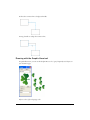
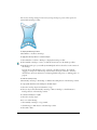
Dragging a button off the toolbar (left), and the result (right)
To customize toolbars by dragging tool buttons:
To move any button from one toolbar to another, hold down Alt (Windows) or Command
(Macintosh), and drag the button to the desired location on the other toolbar.
To duplicate a button for placement on more than one toolbar:
Hold down Alt+Control (Windows) or Option+Command (Macintosh), and drag the button to
the second location.
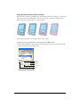
To move a docked toolbar onto the pasteboard:
Drag the gray area of a docked toolbar onto the pasteboard.
A highlight indicates where the toolbar will be dropped if you release the toolbar at that location.
The toolbar becomes a resizable floating toolbar when dropped beyond the toolbar area.
40
Chapter 1
To dock a floating toolbar onto the top, bottom, or side toolbar area:
Drag the gray area of the floating toolbar onto the top, bottom, or side toolbar area.
A highlight indicates where the toolbar will be dropped if you release the toolbar at that location.
The floating toolbar becomes a regular toolbar when dropped in the area surrounding the
pasteboard.
FreeHand Basics
41
42
Chapter 1
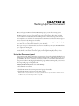
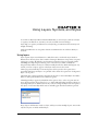
CHAPTER 2
Setting Up Your Document
When you begin your Macromedia FreeHand MX project, you can choose among various
document settings to best meet your design and final output requirements. You use the
Document panel to set page options such as page size and orientation, bleed value, and final
output resolution. You can also use the Document panel to define custom page sizes. You can
create templates to use as defaults for creating new documents. You can also create master pages to
create a consistent look throughout a document.
To aid in aligning and placing objects in your documents, you can set up guides, grids, and page
rulers. You can also set the unit of measure for your document.
If you open or import a document that uses fonts not installed on your system, FreeHand allows
you to replace the missing fonts.
In Windows, you can quickly begin a project and simplify your workflow using FreeHand
wizards, which are interactive screens that guide you through and simplify a variety of tasks.
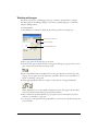
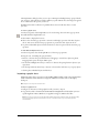
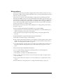
Using the Document panel
The Document panel displays a miniature representation of the pasteboard, with thumbnail icons
for each page in your document. You can use the Document panel to add and remove pages or set
page attributes, such as size, orientation, and bleed, as well as to set document attributes such as
target printer resolution. By dragging thumbnails of pages in the Document panel, you can move
the corresponding pages on the pasteboard.
To display the Document panel, do one of the following:
• Select Window > Document.
• Click the Document tab in the Properties panel group if it is visible.
• Click the Document panel button in the Main toolbar.
Note: The Document panel button does not appear by default when you open FreeHand. To add the button to
your Main toolbar, see “Customizing toolbars” on page 38.
43
Working with pages
You can set page options—including page size, page orientation, and bleed value—using the
Document panel or the Add Pages dialog box. You can also quickly add pages to a document
using the Add Page button.
To set page options:
1
Select Window > Document to display the Document panel if it isn’t already open.
Page size pop-up menu
Page orientation
Page thumbnail views
2
Select a page size from the Page Size pop-up menu.
3
Click one of the page orientation buttons to the right of the Page Size pop-up menu to select a
page orientation: portrait (tall) or landscape (wide).
4
Enter a desired bleed value in the Bleed text box. The paper dimensions must be larger than
the page size you specify. To set the dimensions, select File > Print. For more information on
bleeds, see “Printing” on page 375.
5
Click a page magnification button to enlarge or reduce the size of the page thumbnails.
When magnification is set to the middle or highest level, some of the pages in the document
may not be visible in the Document panel’s pasteboard window.
44
6
Select a value from the Printer Resolution pop-up menu. For more information on printer
resolution, see “Printing” on page 375.
7
To move pages on the pasteboard, drag a thumbnail to a new location in the Document panel
preview window.
Chapter 2
8
To scroll the pasteboard view, hold down the Spacebar while dragging the pasteboard.
To add pages to a document using the Document panel:
1
Click the Document panel Options menu control, and select Add Pages.
2
Set options in the Add Pages dialog box.
3
Click OK.
To add pages to a document from the Document window, do one of the following:
• Click the Add Page button at the bottom of the Document window.
• Select the Page tool in the Tools panel, and Alt-drag (Windows) or Option-drag (Macintosh)
the page.
Selecting pages
To change a page’s attributes, you must first select the page. You can do this directly in your
document, or in the Document panel.
You can also set preferences that let you select a page in the Document window using a tool in the
Tools panel.
To select a page, do one of the following:
• Click the Page tool in the Tools panel and click a single page on the pasteboard.
• In the Document panel, click a page thumbnail.
• Select a page number from the Go to Page pop-up menu in the Status toolbar (Windows) or at
the bottom of the Document window (Macintosh), or enter a value in the text box.
Setting Up Your Document
45
• Click a page selector button in the Status toolbar (Windows) or at the bottom of the
Document window (Macintosh).
• Click the page in the Document window with any tool. For this to work with all tools,
the Using Tools Sets the Active Page option must be selected; see the following procedure.
To set how pages become active:
1
Display document preferences by doing one of the following:
• In Windows, press Control+U, then click the Document tab.
• On the Macintosh, press Command+U, then click the Document category.
2
Select one or both of the following options:
lets you select a page in the Document panel or in the
Document window using the scroll bars. When this option is selected, you can activate a new
page by scrolling through the Document window. The active page appears in the Status toolbar
(Windows) or at the bottom of the Document window (Macintosh), and it is highlighted in
the Document panel.
Changing View Sets the Active Page
lets you use any tool to select a page. When this option is
selected, you can activate a new page by using any tool on the page in the Document window.
Using Tools Sets the Active Page
3
Click OK.
Duplicating, removing, and moving pages
To duplicate, remove, or move pages, you use either the Document panel or the Page tool.
To duplicate a page:
1
Select the page (see “Selecting pages” on page 45).
2
Do one of the following:
• Click the Document panel Options menu control and select Duplicate.
• Using the Page tool, Alt-drag (Windows) or Option-drag (Macintosh) the page in the
workspace.
To remove a page:
1
Do one of the following:
• Select the page in the pasteboard preview of the Document panel. Then click the Document
panel Options menu control and select Remove.
• Using the Page tool, select the page in the workspace, then press Delete.
2
If the selected page contains objects, click OK at the prompt.
Note: To remove a page, you must have more than one page on the pasteboard.
46
Chapter 2
To move a page and its contents, do one of the following:
• Using the Page tool, select the page and drag it to the desired location on the pasteboard.
• In the Document panel, select the page and drag it to the desired location.
To move a page without moving its contents:
1
Using the Page tool, select the page.
2
Start dragging the page, then hold down Control (Windows) or Command (Macintosh) and
continue dragging the page on the pasteboard.
Modifying, resizing, and rotating pages
You can modify page attributes, as well as resize and rotate pages, using the Page tool.
You cannot modify, resize, or rotate a child of a master page; these types of changes must be made
to the master page.
To modify a page:
1
Using the Page tool, Alt-double-click (Windows) or Option-double-click (Macintosh) the page
to open the Modify Page dialog box.
2
Do any of the following:
• Select a new page size from the Page Size pop-up menu. To create a custom size, select Custom
from the pop-up menu and enter the dimensions in the text boxes.
• Select a new page orientation.
• Enter a new bleed size in the text box.
• If a master page is available, select a master page from the Make Child of Master Page pop-up
menu.
3
Click OK.
To snap a page to the grid while resizing it:
1
Verify that View > Grid > Snap to Grid is selected.
For more information, see “Using the grid” on page 54.
2
Click the Page tool in the Tools panel.
3
Click the page you want to resize to display its selection handles.
4
Drag a corner, top, or side handle. To resize the page proportionately, hold down Shift while
you drag.
To rotate a page:
1
Click the Page tool in the Tools panel.
2
Click the page to display its selection handles.
3
Position the pointer outside the page and close to a selection handle. The pointer changes to
the Rotate pointer.
4
Drag to change the page orientation.
Note: Rotating a page does not rotate the objects on the page.
Setting Up Your Document
47
Defining custom page sizes
You can add custom page sizes to a document using the Edit Page Sizes dialog box. Custom page
sizes are based on the document’s current unit of measure. Custom pages cannot be changed; to
edit a custom page definition, you must delete and re-create it.
Custom pages are retained within the FreeHand document. To make a custom page definition
available to newly created FreeHand documents, you add the custom page definition to a
FreeHand template. For more information, see “Using templates” on page 60.
To add a custom page size:
1
Select Window > Document to display the Document panel if it isn’t already open.
2
In the Document panel, select Edit from the Page Size pop-up menu to the left of the page
orientation buttons.
The Edit Page Sizes dialog box appears.
3
Click New.
4
Enter a name for the new custom page in the Page Size text box.
5
Enter the page dimensions in the X and Y text boxes. Values are in the document’s current
units of measure. For more information, see “Setting units of measure” on page 49.
6
Click Close.
To delete a custom page size:
1
In the Document panel, select Edit from the Page Size pop-up menu.
2
In the Edit Page Sizes dialog box, select the custom page size you want to delete.
3
Click Delete.
Deleting a custom page size in the Edit Page Sizes dialog box does not affect custom pages in
your document. Their page type changes to Custom in the Document panel.
To apply a custom page size to a selected page:
Select the custom page size from the Document panel’s Page Size pop-up menu.
To create a new page using a custom page size:
48
1
Click the Document panel Options menu control and select Add Pages.
2
In the Add Pages dialog box, enter the number of pages to be added.
3
Select the custom page from the Page Size pop-up menu.
4
Click OK.
Chapter 2
Setting units of measure
FreeHand offers precision and flexibility for entering numeric values and displaying the rulers
and grid:
• You can choose from points, picas, inches, decimal inches, millimeters, kyus, centimeters, or
pixels to display in the rulers, panels, and dialog boxes.
• You can override the default unit of measure in numeric text boxes. If you override the default
unit of measure, FreeHand automatically converts the value to the default unit of measure. For
example, entering 125m in a text box yields 125 millimeters instead of 125 points; the 125millimeter value is automatically converted to 354.3307 points.
• You can enter mathematical equations and combine units of measure in numeric text boxes to
have FreeHand automatically calculate values for you.
• You can define custom units of measure equivalent to other units of measure, including meters,
feet, miles, ciceros, and didots. For more information, see “Using the rulers” on page 52.
To set the unit of measure for an entire document:
1
Click the Units pop-up menu in the Status toolbar (Windows) or in the bottom of the
Document window (Macintosh).
2
Select a unit of measure.
This setting affects almost all numeric text boxes except the text-related settings based on
points. For example, if the Units pop-up menu is set to inches, entering 12 in a font size text
box yields 12-point type regardless of the unit of measure.
To set a unit of measure other than the default in a numeric text box:
1
Enter a numeric value followed by the unit—i for inches, p for picas, pt for points, m for
millimeters, c for centimeters, and x for pixels.
For example, enter 7p for 7 picas.
2
Press Enter (Windows) or Return (Macintosh).
To specify a value using mathematical functions:
1
Enter numeric values and create an equation using any of the following mathematical symbols:
+ (addition)
– (subtraction)
* (multiplication)
/ (division)
Multiplication and division operations are evaluated before addition and subtraction if you
combine these operations.
You can combine different units in an equation. For example, if the default unit of measure in
the Units menu is set to points, entering 4*50-49, 71+80, or 2i + p7 in a text box yields 151
points. If you enter an invalid equation or unit, FreeHand tries to resolve it or enters 0.
2
Press Enter (Windows) or Return (Macintosh).
Setting Up Your Document
49
Working with master pages
Master pages allow you to easily apply consistent page layouts in a document. You can define page
attributes on a master page, as well as place text and graphics on it, and then apply these attributes
to some or all of the pages in your document. You can create more than one master page in a
document.
Note: You can also use templates to create documents with predefined page layouts. For more information, see
“Using templates” on page 60.
You can create a new master page or convert a current document page to a master page. When
you create a new master page, it takes on the page size, orientation, and bleed settings of the
current page in the document; you can then change these settings if you wish. When you
convert a document page to a master page, the elements on the document page are placed on
the master page.
You can manage master pages in the same way you manage graphic symbols, using the Library
panel. You can group, duplicate, rename, and delete master pages, and you can hide or show them
in the Library panel. For more information on the Library panel, see “Using the Library panel” on
page 297.
You can export master pages to use them with other documents, and import master pages from
other documents for use with the current document. Information about master pages is also
included in a document report. For more information, see “Printing” on page 375.
When working with master pages, keep in mind the following parameters:
• When you apply a master page to a child page, the elements on the master page are placed on
the bottom of each layer in the child page.
• You can bleed objects off of a master page onto the pasteboard. When master pages with bleeds
are applied to child pages, the imaging on the child page is controlled by the bleed rectangle.
Master page’s bleed rectangle
as seen on its child page
Master page and child page
• Selecting a master page from the Master Page pop-up menu in the Document panel makes
the current page (or range of pages) a child (or children) of the master page. Selecting None
makes the current page (or range of pages) an ordinary page (or pages), disassociated from the
master page.
50
Chapter 2
To create a new master page:
1
Do one of the following:
• Select Window > Document to display the Document panel if it’s not already displayed. Then
click the Document panel Options menu control and select New Master Page.
• Select Window > Library to display the Library panel if it’s not already displayed. Then click
the Library panel Options menu control and select New Master Page.
The new master page opens in the master page window and uses the current page’s settings for
size, orientation, and bleed. If the current page is a child of another master page, then the new
master page uses the settings from that master page. These settings can be changed within the
Document panel.
2
Place elements such as text or graphics on the master page.
3
When you have completed the master page layout, close the master page window. The
attributes are saved with the master page symbol in the library.
To convert a page to a new master page:
1
Select the page (see “Selecting pages” on page 45).
2
Click the Document panel Options menu control and select Convert to Master Page.
Note: To convert a child page to a master page, you must first release it. For more information, see the following
procedures.
To apply a master page to a document page:
1
Select the page or pages with the Page tool.
2
Do one of the following:
• In the Document panel, select a master page from the Master Page pop-up menu.
Note: In a multipage document, the selected page is the only page assigned to the master page. If multiple pages
are selected with the Page tool, they all become children of the master page.
• Drag a master page icon from the Library panel and drop it onto a selected document page.
To add a child page to a document, do one of the following:
• Click the Document panel Options menu control and select Add Pages. Select the Make Child
of Master Page option and select a master page from the pop-up menu, then click OK.
• Select a child page and select Duplicate from the Document panel Options menu.
• Using the Page tool, Alt-drag (Windows) or Option-drag (Macintosh) a child page to an
empty location on the pasteboard.
To edit a master page:
1
Do one of the following:
• Double-click the icon of the master page in the Library panel.
• Select a child page and click Edit in the Document panel.
2
Modify the master page as needed.
3
Close the master page window to end the editing session.
Setting Up Your Document
51
To release a child page:
1
Select a page or pages using the Page tool.
Note: The current page must be a child page.
2
Click the Document panel Options menu control and select Release Child Page.
The selected page or pages are no longer based on a master page. Any objects from the master
page are pasted onto the selected page or pages. One group of objects is created for each layer
that contained objects.
To show or hide master pages in the Library panel:
Click the Library panel Options menu control and select Show Master Pages.
This command toggles between showing and hiding master pages. A check mark before the menu
item indicates that master pages are visible (the default).
To import a master page:
1
Click the Library panel Options menu control and select Import.
2
In the dialog box that appears, navigate to locate the folder from which to import the master
page.
3
Click the filename, and click Open.
Note: In Mac OS X, click Choose.
4
Select the master page from the Import Symbols dialog box (Shift-click to select multiple
pages), and click Import.
The lower pane of the Library panel displays the imported master page.
To export a master page:
1
Click the Library panel Options menu control and select Export.
2
Select the master pages you want to export, and click Export.
3
In the dialog box that appears, navigate to locate the folder to which to export the symbol.
4
Enter a filename for the master page, and click Save.
Using the rulers
Rulers help you accurately place and measure objects in your document. They appear at the left
and top of the Document window.
The rulers adjust as you scroll and zoom in the file. The large tick marks indicate the units of
measure (such as points), and the small tick marks indicate the increment (such as 16 points).
Page rulers use the document’s current units of measure, set in the Units pop-up menu in the
Status bar (Windows) or at the bottom of the Document window (Macintosh). You can define
custom units of measure equivalent to meters, feet, yards, miles, nautical miles, kilometers,
ciceros, and didots. You define custom units on a per-document basis.
Note: To make custom units available to newly created FreeHand documents, you can add the custom units to a
FreeHand template. For more information, see “Creating a new default template” on page 61.
52
Chapter 2
To show or hide page rulers:
Select View > Page Rulers > Show.
This command toggles between showing and hiding the rulers. A check mark indicates that the
rulers are visible.
To change the page ruler’s zero point:
Drag the zero-point marker from the upper left corner of the Document window to a new
location on the pasteboard.
Zero-point marker
Note: Zero points can be defined for each individual page in a document.
To reset the page rulers:
Double-click the zero-point marker.
To define custom units of measure:
1
Select View > Page Rulers > Edit.
2
In the Edit Units dialog box, create new custom units by typing a new name or accepting the
default name.
3
Enter numeric values in the text boxes and use the pop-up menus to select the units upon
which to base the custom units of measure.
4
Click Accept.
5
To add more custom units, click the Plus (+) button and perform steps 2-4 for each unit.
6
Click Close when you are finished adding or removing custom units of measure.
Setting Up Your Document
53
To delete custom units of measure:
1
Select View > Page Rulers > Edit to open the Edit Units dialog box.
2
Select the units of measure you want to delete from the Units pop-up menu.
3
Click the Minus (–) button.
4
In the alert dialog box, click OK. Then click Close.
Using the grid and guides
For alignment aids, you can display nonprinting lines as guides or a grid. You can change the
color of these lines.
To change the color of the grid or guides:
1
Display colors preferences by doing one of the following:
• In Windows, press Control+U, then click the Colors tab.
• On the Macintosh, press Command+U, then click the Colors category.
2
To change the color of the guides or grid, click the respective Guide Color or Grid Color box
and select a new color.
3
Click OK.
Using the grid
The grid is a nonprinting background of horizontal and vertical dotted lines. You can use the grid
to align objects precisely, and you can force objects to snap to grid intersections or positions
relative to their original position within a grid cell.
To show or hide the grid:
Select View > Grid > Show.
This command toggles between showing and hiding the grid. A check mark indicates that the
grid is visible.
To turn snapping to the grid on or off:
Select View > Grid > Snap to Grid.
This command toggles between turning snapping to the grid on and off. A check mark indicates
that snapping to the grid is on.
To set grid options:
1
Select View > Grid > Edit.
2
Enter a grid size in the units of measure specified for the current document. (For more
information on setting units of measure, see “Defining custom page sizes” on page 48.)
3
Choose the snapping behavior:
• To force objects to snap to the same relative position within the destination grid cell, select
Relative Grid.
• To force objects to snap to precise grid intersections, deselect Relative Grid.
4
54
Click OK.
Chapter 2
Using guides
Guides are nonprinting lines that help you align and position objects. Guides are blue by default,
but you can change their color if desired (see “Using the grid and guides” on page 54). You can set
guides where you want them using the page rulers or the Edit Guides command. You can add,
modify, and delete guides as needed. You can also lock guides in place. Guides can only exist on
pages; you cannot drag them to the pasteboard.
By default, the Document window does not scroll when you drag a guide. However, you can
set preferences to make this happen. (For more information on setting preferences, see “Using
preferences” on page 25.) You can also change how close objects can be to a guide before
snapping to it, using the Snap Distance preference. For more information, see “Selecting objects”
on page 109.
You can convert paths to guide objects and lock guides using the Layers panel; for more
information, see “Using layers” on page 289.
Note: Guides that reside on a master page can be modified or deleted only from the master page and not from
associated child pages.
To show or hide guides, do one of the following:
• Select View > Guides > Show.
This command toggles between showing and hiding the guides. A check mark indicates that
the guides are visible.
• Click the check mark column beside the Guides layer in the Layers panel.
To add a guide by dragging:
1
If the page rulers aren’t visible, select View > Page Rulers > Show to display them.
2
Drag from the top ruler onto the page to set horizontal guides; drag from the left ruler onto the
page to set vertical guides.
Note: When dragging a guide from a ruler, make sure to release the mouse button while the pointer is over the
page. Otherwise, the guide will be deleted.
To delete a guide:
Drag the guide off the page.
Setting Up Your Document
55
To add guides precisely:
1
Do one of the following:
• Select View > Guides > Edit.
• Double-click an existing guide.
2
Click Add.
3
Select Horizontal or Vertical.
4
Choose an Add By option to add guides:
• Select Count and enter a value to add a precise number of guides.
• Select Increment and enter a value to add guides at set intervals.
5
Enter the first and last position of the guides.
6
Set the page range.
7
Click Add.
8
Repeat steps 2 through 7 to add additional horizontal or vertical guides.
9
Click OK.
To turn guide snapping on or off:
Select View > Guides > Snap to Guides.
This command toggles between snapping and not snapping. A check mark by the menu item
indicates that snapping behavior is active. Snap to Guides is active by default.
The pointer displays a horizontal or vertical triangle when dragging objects near a corresponding
guide, indicating that the object will snap to the guide at that location if released.
To lock or unlock guides, do one of the following:
• Select View > Guides > Lock.
This command toggles between locking and unlocking the guides. A check mark by the menu
item indicates that the guides are locked. Guides are unlocked by default.
• Click the padlock icon beside the Guides layer in the Layers panel.
56
Chapter 2
To edit, release, or delete guides:
1
Do one of the following:
• Select View > Guides > Edit.
• Double-click an existing guide.
2
Select the guide you want to modify.
To modify more than one guide at a time, Control-click (Windows) or Command-click
(Macintosh). Shift-click to select contiguous guides.
3
Do one of the following:
• To edit a guide’s position, click Edit. In the Guide Position dialog box, enter a new location for
the guide and click OK.
• To release the guide or guides, click Release. Releasing a guide converts it into an object.
• To delete the guide or guides, click Remove (Windows) or Delete (Macintosh).
4
Click OK.
To set whether the Document window scrolls when a guide is dragged:
1
Display general preferences by doing one of the following:
• In Windows, press Control+U, then click the General tab.
• On the Macintosh, press Command+U, then click the General category.
2
Do one of the following:
• To make the window scroll when a vertical or horizontal guide is dragged beyond the edges of
the Document window, select Dragging a Guide Scrolls the Window.
• To keep the window from scrolling when a guide is dragged, deselect Dragging a Guide Scrolls
the Window.
3
Click OK.
Setting Up Your Document
57
Creating and opening documents
When you create a new document, it is based on the default document template. To learn more
about templates, see “Using templates” on page 60.
You can open a multipage document, make changes to it, and then save the document. For easy
access, the four most recently saved documents appear in the File > Open Recent menu. When
you quit FreeHand, you have a chance to review any unsaved documents.
You can set document preferences to determine the view and page placement that a document
will have when it’s opened. For more information on setting preferences, see “Using preferences”
on page 25.
In addition to opening FreeHand documents, FreeHand can open files of many other types,
including Adobe Illustrator files, versions 1.1 through 9.
FreeHand allows you to have as many documents open at a time as you like. The only limitation
is your system’s own memory capacity.
To create a new document, do one of the following:
• Select File > New.
• Click the New button in the Main toolbar.
To open an existing document:
1
Select File > Open or click the Open button in the Main toolbar.
2
Locate the file to open, and click Open.
To switch between open documents:
In the Window menu, select the name of the document to display.
To close a file and quit FreeHand:
1
Select File > Exit (Windows) or File > Quit (Macintosh).
Note: In Mac OS X, select FreeHand > Quit FreeHand.
2
If you have not yet saved or named the file, an alert dialog box appears. To save the file, click
Review, and then click Yes (Windows) or Save (Macintosh).
3
Enter a name in the Name text box (if needed), and click Save.
For more information on saving files, see “Saving files” on page 341.
58
Chapter 2
To set preferences that affect how FreeHand handles documents:
1
Display document preferences by doing one of the following:
• In Windows, press Control+U, then click the Document tab.
• On the Macintosh, press Command+U, then click the Document category.
2
Do any of the following:
• To open a document at the same magnification as when it was last saved, select Restore View
When Opening Document.
• To open a document in the same window size and at the same location as the last saved
document, select Remember Window Size and Location.
• To base new documents on a different template, select a template from the New Document
Template pop-up menu, or click the Ellipsis (…) button (Windows) or the Select button
(Macintosh) and locate another template file. For more information on using templates, see
“Using templates” on page 60.
• To review and save each open document when quitting the application, select Always Review
Unsaved Documents upon Exit (Windows) or Always Review Unsaved Documents upon
Quit (Macintosh).
• To locate broken links to graphics, select Search for Missing Links (Macintosh only).
• To restore your default preferences, Click Defaults.
3
Click OK.
Opening documents from previous versions of FreeHand
FreeHand MX can open documents created in FreeHand 8 and later versions.
Because some of the FreeHand features change between versions, some illustration attributes
may change or be omitted when an illustration is converted. After converting a document from
an earlier version, make sure FreeHand displays and prints it properly before you delete the
original document.
To convert a file from a previous version of FreeHand:
Open the file in FreeHand MX.
The converted file’s name becomes Filename.FH11 (Windows) or Filename (Converted)
(Macintosh).
Setting Up Your Document
59
Using templates
To work more efficiently and avoid design inconsistencies, you can create templates for
documents that share common design elements and production settings. You can then use these
templates as defaults for creating new documents.
You can also use master pages to apply page layouts to individual pages. For more information,
see “Working with master pages” on page 50.
A template’s settings and attributes are defaults for creating other documents. To create new
documents with the same objects, settings, colors, and object and paragraph styles as those of an
existing document, you can save the existing document as a template.
A template file saves the following elements of a FreeHand document:
•
•
•
•
•
•
•
•
•
•
Guides
Layer information
Graphic styles
Text styles
Symbols and master pages
All objects
Custom brushes
Custom colors
Custom page sizes
Custom units of measure
When you open a template, an untitled copy of the template document appears. You use the
untitled copy to create a new template or replace an existing template. You can also designate a
template as the default for all new documents.
To save a document as a template:
1
Select File > Save As.
2
Enter a name for your template file in the Save Document dialog box (Windows) or Save
dialog box (Macintosh).
3
Select FreeHand Template from the Save as Type pop-up menu (Windows) or from the
Format pop-up menu (Macintosh).
4
Select a destination and click Save. In Windows, the extension .ft11 is added to the filename.
To edit a FreeHand template:
1
Open the template, make changes, and then select File > Save As.
2
Save the newly revised document as a template with the same name and location.
3
FreeHand prompts you to replace the original template file. Click Yes (Windows) or
Replace (Macintosh).
The edited template replaces the old one.
60
Chapter 2
To convert any FreeHand file into a template without opening it (Macintosh):
1
Select the FreeHand file in the Finder.
2
Select File > Get Info or File > Show Info and then select Stationery Pad.
To convert a template into a regular FreeHand document, deselect Stationery Pad.
To change the default template:
1
Display document preferences by doing one of the following:
• In Windows, press Control+U, then click the Document tab.
• On the Macintosh, press Command+U, then click the Document category.
2
Do one of the following:
• Select a template from the New Document Template pop-up menu.
• Click the Ellipsis (…) button (Windows) or the Select button (Macintosh) and locate another
template file.
3
Click OK.
Creating a new default template
Using the default template, you can apply document-level defaults to control settings in
documents as a whole. You can apply object-level defaults to the default template to control
settings for selected objects.
To create a new default template:
1
Select File > New.
2
Modify the document.
For example, you can change the page size, default colors in the color list, default font size, and
magnification, and save these with the template.
3
Select File > Save As.
4
Select FreeHand Template from the Save as Type pop-up menu (Windows) or from the
Format pop-up menu (Macintosh).
Setting Up Your Document
61
5
Name the file and save it in the Macromedia/FreeHand/11/English/Settings folder within your
user-specific Application Data (Windows) or Application Support (Macintosh) folder. In
Windows, the extension .ft11 is added to the filename.
The location of your user-specific Application Data or Application Support folder can vary
depending upon your operating system. For information on how to locate this folder, see your
operating system’s documentation.
Tip: A quick way to locate your user-specific folder is to go to the Document tab or category in the Preferences
dialog box, click the Ellipsis (...) button (Windows) or the Select button (Macintosh) beside New Document
Template, and examine the path to the current default document template.
Linking and embedding
You can set preferences to determine whether to link or embed a bitmap, SWF, or EPS graphic
when you import it into a FreeHand document. An embedded graphic is included in the
document; a linked file remains independent of the file, resulting in a smaller FreeHand
document.
Embedding is useful for transporting an illustration without breaking the link, but it results in a
larger file and increases the memory needed to display the document.
Note: Do not embed a DCS EPS 1.0 file in a FreeHand document. A DCS 1.0 file is actually five separate files: a
low-resolution, composite preview and a separate file for each process (CMYK) color. If you try to embed the file,
only the low-resolution file is embedded.
When you link to a graphic, FreeHand displays a preview of the graphic in the document. When
you print or export a linked graphic, FreeHand requires that the link be maintained. If you move
or rename linked graphics, you may have to relink them to display or print your document.
Linked graphics are easier to update after they are modified, because the graphics update
automatically when the document opens. However, storing linked images on a network server can
slow FreeHand performance.
To link a graphic:
1
Display import preferences by doing one of the following:
• In Windows, press Control+U, then click the Import tab.
• On the Macintosh, press Command+U, then click the Import category.
62
2
Deselect the Embed Images and EPS upon Import option and the Convert Editable EPS
When Imported option.
3
Click OK.
4
Select File > Import.
5
Navigate to the graphic you want to import.
Chapter 2
6
Double-click the filename.
The import pointer appears.
Import pointer
7
Position the import pointer where you want the graphic or text block’s upper left corner to
appear.
8
Place the graphic by doing one of the following:
• Click to place the graphic at its default size.
• To resize an image while importing, drag the import pointer to create a marquee. Release the
mouse button when the marquee is the correct size.
To always embed graphics:
1
Display import preferences by doing one of the following:
• In Windows, press Control+U, then click the Import tab.
• On the Macintosh, press Command+U, then click the Import category.
2
Select the Embed Images and EPS upon Import option.
3
Deselect the Convert Editable EPS when Imported option.
4
Click OK.
Managing links
When linking or embedding a graphic, FreeHand records the graphic’s filename and location.
When you open, export, or print the illustration containing a link, FreeHand looks for the linked
graphic by its filename. If the source graphic is not in its original folder, FreeHand looks for it in
the same folder as the FreeHand document.
When moving a document to another computer or to a storage device for transport, follow these
guidelines:
• Save the linked graphics in the same folder as the document or embed all the graphics in
the document.
• When preparing a document to send to a service bureau, use the Collect for Output command
to gather all needed components, including linked graphic files. For more information, see
“Printing” on page 375.
• Use the Search for Missing Links feature (Macintosh). For more information, see “Updating
and fixing broken links upon opening a document” on page 65.
Setting Up Your Document
63
To update a link to a graphic after you have opened the document:
1
Do one of the following:
• Select Edit > Links to display the Links dialog box.
• In the Object panel, click the Links button when the graphic is selected in the document.
The Links dialog box appears, listing all imported graphic files. The file information for files
with broken links appears in italics. The Kind column lists the type of image (such as TIFF,
SWF, EPS, or grayscale). The Size column displays the size of the file. The Page column lists
the page number of the document on which the upper left corner of the image appears.
2
Do any of the following:
• To view information on a linked graphic, such as name, location, last modified date, kind, size,
and a thumbnail of the graphic, select the file in the list and click Info. Click OK when you’re
finished viewing the information.
• To update or reestablish a link, select the file with the broken link from the list and click
Change. Then navigate to the renamed or moved file and click Open.
• To embed an image, select the file in the Links dialog box, and click Embed.
To extract an embedded graphic from a document and create a new link to an external graphic file:
1
Do one of the following:
• Select Edit > Links. Select the graphic in the list and click Extract.
• With the graphic selected in the document, click the Links button in the Object panel and
then click Extract.
64
2
In the Extract Import dialog box, select the folder you want to extract to.
3
Accept the default name or enter a new name in the File Name text box.
4
Click Save.
5
If you’re saving over an existing file, a dialog box appears asking if you want to replace the
existing file. Click Yes to replace the file, or click No and navigate to a new location.
6
Click OK.
Chapter 2
Updating and fixing broken links upon opening a document
If you try to open a document with a broken link to a graphic, you’ll be prompted to locate
the link.
To locate a missing link:
1
Select File > Open.
2
Navigate to locate the file to open. Click Open.
3
In the Locate File dialog box, navigate to locate the missing file, and select it.
Note: Select Search the Current Folder for Missing Links to have FreeHand look in this folder if any other
broken links are encountered while the file is being opened. Click Ignore or Ignore All to prevent a graphic (or
graphics) from being relinked.
4
Click Open.
The document is updated with the new link.
5
Save the document.
To set preferences for searching for missing links (Macintosh):
1
Press Command+U, then click the Document category.
2
Select Search for Missing Links and click the Select button to search a specified folder and its
subfolder for missing links.
FreeHand searches up to 10 subfolders deep for a missing link; if FreeHand finds the graphic,
the application automatically relinks the placed graphic to the new location.
3
Click Select, then click OK.
Handling font substitution
If you open or import a file that uses fonts not installed on your system, you can choose to replace
the missing fonts or substitute fonts installed on your system. You may also have to reapply or
substitute fonts if you transfer a document between Windows and Macintosh platforms, if the
original fonts are not available on the other platform, or if the fonts have different names. You can
use Macromedia Fontographer to create compatible versions of fonts for both Windows and the
Macintosh; for more information on Macromedia products, go to the Macromedia website at
www.macromedia.com.
Replacing fonts strips all manual kerning applied to the fonts. Substituting fonts temporarily
substitutes fonts when the illustration is opened.
Setting Up Your Document
65
Replacing missing fonts
If you open or import a file containing fonts that are not installed on your system, the Missing
Fonts dialog box prompts you to replace the missing fonts. Any missing fonts not replaced will
display and print in the default replacement font, Arial (Windows) or Courier (Macintosh);
however, the font assignment in the document remains the same.
To replace missing fonts:
1
Do one of the following:
• Select File > New to open a new file. Then select File > Import to import a file.
• Select File > Open and open a file.
The Missing Fonts dialog box appears.
2
Highlight a font in the list, or click Select All to select all missing fonts.
3
Click Replace to open the Replace Font dialog box. Select the font name and style with which
to replace the specified font or fonts, then click Change.
4
Do one of the following:
• Click OK to open the document with the new fonts.
If you didn’t click Replace to replace missing fonts prior to clicking OK, the missing fonts are
temporarily displayed and printed in system default fonts.
• Click Cancel to cancel opening the document.
Automatic font substitution
If you use the Adobe Type Manager (ATM) font substitution feature, ATM temporarily
substitutes fonts when the illustration is opened, and the Missing Fonts dialog box does
not appear.
ATM automatically applies each missing font’s metrics and weight to a multiple master font and
marks the font name with a diamond in the font menu. Line breaks and word spacing are
preserved, but the subtleties of the letterforms may be lost.
If you are concerned about typography, open the ATM control panel and deselect Enable Font
Substitution (Macintosh only).
66
Chapter 2
Sending mail (Windows)
If your Windows system includes an MAPI32-compliant electronic mail system, you can create a
new outgoing mail message with the active FreeHand document or all open documents attached.
To send an e-mail message with an attached FreeHand document:
1
Select File > Send.
2
Do one of the following:
• To attach the active document to your e-mail message, select the filename.
• To attach all currently open documents to your e-mail message, select All Open Documents.
The first time you send mail, a window appears asking you to set up a profile. See your e-mail
application’s documentation for more information.
3
Add any additional message.
4
To add the e-mail addresses, type an address in the text box or click To.
5
Click Send.
The documents are attached in their current state. If the documents are unnamed, they are
attached with the default names.
Using AppleScript to automate FreeHand (Macintosh)
On the Macintosh, you can automate some FreeHand functions, including document
manipulation, printing, report generation, and the Find and Replace function, using AppleScript
and the AppleScript Script Editor (available from Apple).
To use AppleScript capabilities in FreeHand, you must have AppleScript and the AppleScript
Script Editor installed on your computer. You write scripts using the AppleScript Script Editor
and run them either from the Script Editor or by saving a script as an application and launching it
from the desktop or Apple menu.
To get more information on AppleScript commands used by FreeHand:
1
Launch the AppleScript Script Editor.
2
Follow the instructions in the AppleScript Read Me file to select FreeHand MX as the
dictionary. The AppleScript Read Me is located in the ReadMes folder in the FreeHand MX
application folder.
For more information on the AppleScript Script Editor or other AppleScript commands, see the
AppleScript Read Me or the AppleScript Handbook by Danny Goodman, Random House
Electronic Publishing.
Setting Up Your Document
67
Working with wizards (Windows)
In Windows, you can quickly begin a project and simplify your workflow using FreeHand
wizards. Wizards are interactive screens that guide you through and simplify a variety of tasks.
To use a wizard:
1
Select Help > Wizards.
2
Select a topic:
lets you create a new document, open the previous document, select and open a
document from a list, open a template, or launch FreeHand Help. This screen appears when
you launch FreeHand.
Welcome
Setup creates a document based on an illustration style, freehand or technical. Select colors,
color mode, unit of measure, page size, and page orientation.
creates a document optimized for creating graphics, for either the Internet or
multimedia/image editing. Select colors and set the size and orientation for onscreen designs.
Screen-based
Stationery creates common business documents: letterhead, envelopes, and business cards.
Select colors and a standard paper size. You also can browse through various layout ideas.
creates multipage documents. Select page size, number of pages, page orientation,
colors, unit of measure, and styles.
Publication
3
Follow the onscreen instructions.
Note: Some wizard settings let you add more than one preset color palette to the swatches.
68
Chapter 2
CHAPTER 3
Drawing
Macromedia FreeHand MX gives you a wide range of options for drawing. You can drag to create
simple objects, such as rectangles, ellipses, and lines. You can also drag to create more complex
shapes, including spirals, stars, and polygons. Most drawing tools let you set options. For
example, you can change the number of sides on a polygon or the direction in which a
spiral winds.
You can create paths by placing points with the Pen or Bezigon tools, or by drawing a freeform
shape with the Pencil tool. You can change the type of points and edit them to adjust the shape of
the path segments that join them. FreeHand also lets you edit paths by removing or adding
points, combining paths, and dragging path segments into new shapes.
You can use other tools to create specialty objects. For example, the Chart tool lets you add charts
to your drawings. The Connector tool lets you create connector lines that dynamically adjust as
you reposition objects within your drawing. The Graphic Hose tool lets you draw using a picture
as your “paintbrush.”
About vector graphics
Paths connected by points are the basic elements of FreeHand objects. A path consists of at least
two points, each connecting one or more line segments, either straight or curved.
FreeHand generates lines and curves, called paths, which describe graphics according to their
mathematical characteristics. Graphics constructed this way are much smaller in file size than
bitmap graphics. Vector graphics are also resolution-independent—they appear crisp and smooth
onscreen or when printed regardless of the monitor or printer resolution.
69
In contrast, bitmap images consist of a matrix of pixels whose display depends on the resolution
of your monitor and printer. Bitmap images appear granulated when enlarged.
Vector image (top) and bitmap image (bottom)
FreeHand is a vector drawing program, but you can work with bitmap images in several ways.
You can rasterize FreeHand objects, which means to convert them to bitmap images within your
document. For more information, see “Converting vector graphics to bitmap images” on page
326. You can also export an entire FreeHand document or selected objects to a bitmap file format.
For more information, see “Exporting bitmap images” on page 352.
You can import or copy a bitmap image into a FreeHand drawing. For example, you can import a
photograph of a rose, an image that would be difficult to create using vector graphics, to enhance
a drawing. (For more information, see Chapter 10, “Using Imported Artwork,” on page 309.)
Macromedia FreeHand MX can import a wide variety of vector and bitmap graphic formats.
You can also trace a bitmap image in FreeHand. The Trace tool creates paths that follow the
outlines of a bitmap image. For example, you can import a photograph of a cow, and then
trace the cow’s outline or just the cow’s spots. For more information, see “Tracing bitmaps” on
page 323.
70
Chapter 3
Path and point characteristics
Paths and points have the following basic characteristics:
• A path can be open with unconnected end points, or closed with the same beginning and
ending point.
Examples of open (top) and closed (bottom) paths
• Each path can have up to 32,000 points, which lets you import complex files from other
sources. However, using more points increases file size and slows redrawing and printing.
• Paths can be outlined by one or more strokes of varying widths and filled with color, gradients,
or patterns. Paths can also be filled with vector images, bitmap images, or tiled fills.
Fill
Stroke
By default, an open path doesn’t have a fill, but you can change this behavior. For more
information, see “Setting path and point display preferences” on page 73.
Drawing
71
• Paths have either clockwise or counterclockwise direction. The Rectangle, Polygon, and Ellipse
tools draw in a clockwise direction. With the Line tool, the direction in which you draw sets
the path direction. With the Pen and Bezigon tools, the order in which you place points sets
the path direction.
Ending point
Beginning point
Beginning and ending point
The path direction affects path operations (see “Changing a path’s direction” on page 95) and
blending.
72
Chapter 3
• Different types of points anchor path segments and let you edit lines and curves in different
ways by adjusting their handles.
Corner point
Connector point
Curve point
FreeHand places a corner point, which is displayed as a square, when you draw a straight path
segment. A corner point’s handles can be adjusted independently. When you first select a
corner point, its handles are retracted.
FreeHand places a curve point, which is displayed as a circle, when you draw a curved path
segment. A curved point’s handles move in tandem. When you first select a curve point, its
handles are extended. When unselected, curve points display as squares.
Connector points, which are displayed as triangles, let you make a smooth transition between a
straight path segment and a curved one. The position of adjacent points limits how much you
can adjust a connector point’s handles and whether its handles are initially extended or
retracted. When unselected, connector points display as squares.
Setting path and point display preferences
You can set your preferences to change the way FreeHand displays paths and points. This can
make it easier to select and edit a path or point, particularly in a complex drawing.
You can also change the way fills are displayed for a new open path.
To set the display preferences for selected paths and points:
1
Display general preferences by doing one of the following:
• In Windows, press Control+U, then click the General tab.
• On the Macintosh, press Command+U, then click the General category.
2
Select one or more options:
Smaller Handles
displays smaller points and handles.
Show Solid Points
displays points as a solid shape. Deselect this option to display points as
an outline.
3
Click OK.
Drawing
73
To set the display preferences for a fill in an open path:
1
Display object preferences by doing one of the following:
• In Windows, press Control+U, then click the Object tab.
• On the Macintosh, press Command+U, then click the Object category.
2
Select Show Fill for New Open Paths if you want an open path’s fill to be displayed. This
option applies only to paths created after you have set this preference.
3
Click OK.
Drawing rectangles, ellipses, and lines
Rectangles, ellipses, and lines are the basic FreeHand shapes. You can draw basic shapes by
dragging with one of these tools. You can also precisely adjust the size and position of rectangles,
and adjust the curve of rectangle corners.
Line
Rectangle
Ellipse
Rectangles and ellipses are drawn as grouped objects. If you ungroup a rectangle or ellipse,
FreeHand converts it to a path, and you can no longer edit it as a rectangle or ellipse.
To draw a rectangle, ellipse, or line:
74
1
In the Tools panel, select the Ellipse tool, or select the Rectangle or Line tool from its
pop-up menu.
2
Drag to define the object, and then release the mouse button to end the path.
Chapter 3
To draw a rectangle, ellipse, or line from its center:
1
In the Tools panel, select the Ellipse tool, or select the Rectangle or Line tool from its
pop-up menu.
2
Hold down Alt (Windows) or Option (Macintosh) as you drag the respective tool.
Drawing rectangles with curved corners
You can precisely edit the curvature of rectangle corners by using the Object panel. The corners of
a rectangle can be uniform, or you can edit corners individually by unlocking them in the Object
panel. Locked corners edit uniformly, even if some of the remaining corners are unlocked.
You can also edit corners manually by using the subselect tool to drag radius handles of a
rectangle.
To draw rectangles with curved corners:
1
In the Tools panel, if the Rectangle tool is not showing, select it from its pop-up menu.
2
Double-click the Rectangle tool.
3
In the Rectangle Tool dialog box, enter a value or use the slider to adjust the corner radius,
from 0 for a standard 90° corner to 100 for extremely curved corners.
4
Click OK.
5
Draw the rectangle.
To adjust the corners of a selected rectangle uniformly:
1
In the Tools panel, click the Subselect tool.
2
Select the rectangle.
3
Drag a radius handle.
Drawing
75
To adjust the corners of a selected rectangle independently:
1
In the Tools panel, click the Subselect tool.
2
Select the rectangle.
3
In the Object panel, deselect Uniform.
4
Drag a radius handle.
Constraining a basic shape as you draw
You can constrain how a tool draws a basic shape. When constrained, the Rectangle tool draws a
square, the Ellipse tool draws a circle, and the Line tool draws at increments of 45°.
You can change the constrain angle. When the constrain angle is 0°, holding down the Shift key
constrains objects to 0°, 45°, 90°, and so on. Changing the constrain angle shifts these angles by
the specified amount. A constrain angle of 10°, for example, changes the angles to 10°, 55°, 100°,
and so on. If you change the constrain angle, a rectangle, line, or ellipse that you draw will be
tilted to the value you specified.
To constrain a shape as you draw, do one of the following:
• To constrain a shape, hold down Shift as you drag the pointer.
• To constrain a shape as you draw from the center, hold down Alt (Windows) or Option
(Macintosh) and Shift-drag the pointer.
76
Chapter 3
To set the constrain angle:
1
Select File > Document Settings > Constrain.
2
Enter a value in the Angle text box, or use the pop-up angle dial to set the angle.
3
Click OK.
Repositioning a basic shape as you draw
You can move a rectangle, line, ellipse, polygon, or star as you draw.
To reposition a basic shape while drawing, do one of the following:
• Hold down the Spacebar.
• (Windows only) Hold down the right mouse button.
Drawing polygons and stars
You can use the Polygon tool to draw polygons and stars. When you draw a polygon, you create a
closed path. The Polygon tool draws from the center.
To set Polygon tool options:
1
In the Tools panel, if the Polygon tool is not showing, select it from its pop-up menu.
2
Double-click the Polygon tool.
3
In the Polygon Tool dialog box, select Polygon or Star for the shape.
4
Set the number of sides by dragging the slider or entering a value from 3 to 360. Values above
20 will create a nearly round object.
5
For a star, set the angle of the star points. Select Automatic to draw a preset star shape, or
Manual to set a shape using the Acute/Obtuse slider.
The preview window displays the setting results.
6
Click OK.
Automatic (left), Acute (center), and Obtuse (right)
Drawing
77
To draw a polygon or star:
1
In the Tools panel, select the Polygon tool from its pop-up menu.
2
Drag to draw a polygon or star.
3
To modify the polygon or star as you draw, use any of the following keys:
• Press Shift to constrain the angles of the polygon.
• Press Alt (Windows) or Option (Macintosh) to draw from the center regardless of the selected
drawing option.
To edit a polygon or star:
1
In the Tools panel, click the Subselect tool.
2
Select the polygon or star.
3
Do either of the following:
• Drag a diamond-shaped handle to uniformly edit the vertices, or “peaks,” of the polygon
or star.
• Drag a circular handle to uniformly edit the midpoints, or “valleys,” of the polygon or star.
Midpoint
Vertex
4
78
To constrain the vertices or midpoints to the original angle of the polygon or star, press Shift as
you drag.
Chapter 3
Drawing spirals and arcs
With the Spiral and Arc tools, you can easily draw spirals and arcs. Options let you customize the
way each tool works.
To set Spiral tool options:
1
In the Tools panel, if the Spiral tool is not showing, select it from its pop-up menu.
2
Double-click the Spiral tool.
3
In the Spiral dialog box, select a Spiral Type option:
• Click the left button to create a spiral with a concentric, evenly spaced radius.
• Click the right button to create an expanding-radius spiral that opens up farther with
each rotation. In the Expansion text box, enter a value or drag the slider to adjust the
expansion rate.
4
Select a Draw By option:
specifies the number of rotations in the spiral, regardless of its size. Set the number
by entering a value in the Number of Rotations text box or by adjusting the slider.
Rotations
Increments adds more rotations as the spiral grows bigger. Set the spacing between each
rotation by entering a value in the Increment Width text box or by adjusting the slider. For
expanding spirals, enter a value in the Starting Radius text box.
5
Select a Draw From option:
Center
Edge
lets you click to set the center point of the spiral and drag to place the end point.
lets you click to place the end point of a spiral and drag to place the center point.
Corner
lets you click to place one end point of a spiral and drag to place the other end point.
6
Click a Direction button to specify whether a spiral turns clockwise or counterclockwise. This
does not change the path direction of a spiral.
7
Click OK.
To draw a spiral:
1
In the Tools panel, select the Spiral tool from its pop-up menu.
2
Drag to draw a spiral.
3
To modify the spiral as you draw, use any of the following keys:
• Press Shift to constrain the placement of the final point.
• Press Alt (Windows) or Option (Macintosh) to draw from the center regardless of the selected
drawing option.
Drawing
79
To set Arc tool options:
1
In the Tools panel, if the Arc tool is not showing, select it from its pop-up menu.
2
Double-click the Arc tool.
3
In the Arc dialog box, select from the following options:
Create Open Arc lets you draw only the arc curve. Deselect this option to draw the arc as a
quarter pie shape.
Create Flipped Arc
lets you flip the orientation of the arc.
Create Concave Arc
lets you draw the arc with an outer corner.
Concave (left), Open (center), and Flipped (right)
4
Click OK.
To draw an arc:
1
In the Tools panel, select the Arc tool from its pop-up menu.
2
Drag to draw an arc.
3
To modify the arc as you draw, press any of the following keys, alone or in combination, after
you begin drawing the arc:
•
•
•
•
Press Shift to constrain the arc.
Press Alt (Windows) or Option (Macintosh) to draw a flipped arc.
Press Control (Windows) or Command (Macintosh) to draw a closed arc.
(Windows only) Press Control and hold down the right mouse button as you draw to create a
concave arc.
• (Macintosh only) Press Control to draw a concave arc.
80
Chapter 3
Drawing freeform paths
With the Pencil, Variable Stroke Pen, and Calligraphic Pen tools, you can draw freeform paths
that follow the direction of your hand movements.
Drawing with the Pencil tool
The Pencil tool draws a simple line as you drag.
To set Pencil tool options:
1
In the Tools panel, if the Pencil tool is not showing, select it from its pop-up menu.
2
Double-click the Pencil tool.
3
In the Pencil Tool dialog box, select tool options:
• Enter a value from 1 to 10 in the Precision text box, or adjust the slider. Choose a high value
to follow minor variations as you draw. Choose a low value to smooth minor variations as
you draw.
• Select Draw Dotted Line to draw paths faster by displaying a dotted line as you draw. The final
path is still solid.
4
Click OK.
5
Use the stroke and fill color selectors in the Tools panel to set color attributes for the path.
To draw a path with the Pencil tool:
1
In the Tools panel, select the Pencil tool from its pop-up menu.
2
Drag to draw a path. To draw a straight line, hold down Alt (Windows) or Option
(Macintosh) as you drag.
To continue a selected path with the Pencil tool:
Position the Pencil tool over a path’s end point; a solid plus (+) sign indicates that drawing will
continue the path.
Drawing with the Variable Stroke Pen tool
The Variable Stroke Pen tool draws a path that resembles a brush stroke. You can use keyboard
commands or a pressure-sensitive tablet to vary the width of the path as you draw.
To set Variable Stroke Pen tool options:
1
In the Tools panel, if the Variable Stroke Pen tool is not showing, select it from its
pop-up menu.
2
Double-click the Variable Stroke Pen tool.
3
In the Variable Stroke Pen dialog box, select tool options:
• Enter a value from 1 to 10 in the Precision text box, or adjust the slider. Choose a high value
to follow minor variations as you draw. Choose a low value to smooth minor variations as
you draw.
• Select Draw Dotted Line to draw paths faster by displaying a dotted line as you draw. The final
path is still solid.
Drawing
81
• Select Auto Remove Overlap to remove unnecessary path segments and create a composite
path.
Original (left) and Auto Remove Overlap applied (right)
Note: Using the Auto Remove Overlap option may slow the redrawing of an image. You can also remove any
overlap by selecting the path and choosing Modify > Alter Path > Remove Overlap or clicking the Remove
Overlap button on the Xtra Operations toolbar.
• For Width, set the minimum and maximum possible stroke widths, measured from the
centerline, between 1 and 72 points.
4
Click OK.
5
Use the stroke and fill color selectors in the Tools panel to set color attributes for the path.
To draw a path with the Variable Stroke Pen tool:
1
In the Tools panel, select the Variable Stroke Pen tool from its pop-up menu.
2
Drag to draw a path.
3
To draw a straight line, hold down Alt (Windows) or Option (Macintosh).
Drawing with the Calligraphic Pen tool
The Calligraphic Pen tool draws a path that resembles a calligraphy stroke. You can use keyboard
commands or a pressure-sensitive tablet to vary the width of the path as you draw.
To set Calligraphic Pen tool options:
1
In the Tools panel, if the Calligraphic Pen tool is not showing, select it from its pop-up menu.
2
Double-click the Calligraphic Pen tool.
3
In the Calligraphic Pen dialog box, select tool options:
• Enter a value from 1 to 10 in the Precision text box, or adjust the slider. Choose a high value
to follow minor variations as you draw. Choose a low value to smooth minor variations as
you draw.
• Select Draw Dotted Line to draw paths faster by displaying a dotted line as you draw. The final
path is still solid.
82
Chapter 3
• Select Auto Remove Overlap to remove unnecessary path segments and create a composite
path.
Original (left) and Auto Remove Overlap applied (right)
Note: Using the Auto Remove Overlap option may slow the redrawing of an image. You can also remove any
overlap by selecting the path and choosing Modify > Alter Path > Remove Overlap or clicking the Remove
Overlap button on the Xtra Operations toolbar.
• Select Fixed to set calligraphic paths to a constant width, or click Variable to specify a path
width between 1 and 72 points.
• Set the angle of the Calligraphic Pen by entering a value or dragging the Angle dial from 0° to
359°. The actual width of a stroke at a given location on the path depends on the direction in
which you drag.
4
Click OK.
5
Use the stroke and fill color selectors in the Tools panel to set color attributes for the path.
Select no stroke and a basic fill to most closely resemble a real calligraphy pen.
Drawing
83
To draw a path with the Calligraphic Pen tool:
1
In the Tools panel, select the Calligraphic Pen tool from its pop-up menu.
2
Drag to draw a path.
3
To alter the path as you draw, do any of the following:
• Hold down Alt (Windows) or Option (Macintosh) to draw a straight line.
• To decrease the path width, press the Left Arrow key (Windows) or Left Bracket key
(Macintosh).
• To increase path width, press the Right Arrow key (Windows) or the Right Bracket key
(Macintosh).
• If you’re using a pressure-sensitive tablet, the width of the path segments increase or decrease
according to the amount of pressure applied.
To continue a selected path with the Calligraphic Pen tool:
Position the Pencil tool over a path’s end point; a solid plus (+) sign indicates that drawing will
continue the path.
Drawing with the Pen tool and Bezigon tool
You can use the Pen tool and Bezigon tool to draw by placing points to define a path. These tools
differ in the way they place points. As you move the Pen or Bezigon pointer (cursor), it changes to
show what action will result if you click at the current location.
• The Pen tool lets you adjust a point’s handles, and therefore the curvature of a path, as you
draw. Click to place a point, then drag to adjust the handles. Use the Pen tool to create a path
with curved segments. After you place the first point, the Pen tool shows a “rubberband”
preview of what the path will look like when you click to place the next point.
• The Bezigon tool sets point locations. Click to place a point, then continue dragging to move
that point. Use the Bezigon tool to create a path with straight segments.
Drawing with the Pen tool
Drawing with the Bezigon tool
84
Chapter 3
To draw with the Pen tool:
1
In the Tools panel, select the Pen tool from its pop-up menu.
2
Do any of the following:
• Click to place a corner point.
• Drag to place a curve point and extend its handles. Press Control (Windows) or Command
(Macintosh) as you drag to move the curve point to a new location.
• Hold down Alt and right-click (Windows) or Control-click (Macintosh) to place a
connector point.
Dragging as you place a connector point extends the point’s handle. This handle affects the
curve of the next path segment.
3
To finish the path, do one of the following:
• Double-click the last point or press Tab to create an open path.
• Click the first point to create a closed path.
To draw with the Bezigon tool:
1
In the Tools panel, select the Bezigon tool from its pop-up menu.
2
Do one of the following:
• Click to place a corner point.
• To place a curve point, hold down Alt (Windows) or Option (Macintosh) as you click.
• To reposition a point and the point handles simultaneously, hold down Control (Windows) or
Command (Macintosh) and drag the point to its new location.
• To place a connector point that connects a straight segment to a curved path: In Windows,
hold down Alt and use the right mouse button to drag; on the Macintosh, Control-drag.
3
To finish the path, do one of the following:
• Double-click the last point or press Tab to create an open path.
• Click the first point to create a closed path.
To constrain path segments:
Hold down Shift as you place a point.
To continue a selected path:
1
In the Tools panel, click the Subselect tool.
2
Select an end point on the path you want to continue.
3
In the Tools panel, select the Pen tool or Bezigon tool from their pop-up menu. You can
continue a Pen path with the Bezigon tool and vice versa.
4
Click or drag to draw additional segments.
Drawing
85
To continue an unselected path:
1
In the Tools panel, select the Pen tool or Bezigon tool from their pop-up menu. You can
continue a Pen path with the Bezigon tool and vice versa.
2
Move the pointer over an end point of the path you want to continue.
3
Alt-drag (Windows) or Option-drag (Macintosh) to extend the path.
4
Click or drag to draw additional segments.
To close a selected open path, do one of the following:
• Use the Pointer or Subselect tool to drag one end point over the other end point.
• Select Window > Object. In the Object panel, select Closed to automatically connect the end
points of the path with a new path segment.
• (Windows only) Right-click the path and select Path > Closed from the context menu.
To open a selected closed path, do one of the following:
• Select Window > Object. In the Object panel, deselect Closed to remove the last path segment
from the path.
• (Windows only) Right-click the path and select Path > Open from the context menu.
Editing paths
You can easily edit paths using various tools and techniques. Once you’ve drawn a path, you can
add or delete points, reposition points, or redirect the path.
You can edit paths using the Pen, Bezigon, Pointer, and Subselect tools. You can reshape paths
using the Freeform tool, split paths with the Knife tool, or erase parts of paths with the Eraser
tool. You can also apply Xtras to simplify paths by reducing the number of points.
You can also control path display and behavior using the Object panel.
Adding and deleting path segments and points
Deleting one or more segments from a path leaves one or more open paths.
To delete a path segment or point:
1
In the Tools panel, click the Subselect tool.
2
Click the path to select it.
3
Click a point or path segment to select it. Shift-click to select additional segments or points.
4
Press Delete.
To manually add points to a selected path:
86
1
In the Tools panel, select the Pen tool from its pop-up menu.
2
Click the path to place a new corner point.
Chapter 3
To automatically add points to a selected path:
Select Window > Toolbars > Xtra Operations. Click the Add Points button on the Xtra
Operations toolbar, or select Xtras > Distort > Add Points.
A point is added halfway between every pair of points on a path.
Reshaping a path
Using the Pointer and Subselect tools, you can reshape a path by moving points and path
segments. You can also adjust the points on a path by dragging with the Pointer tool or by using
the Object panel.
You can also modify a path by using the Freeform tool; see “Editing a path with the Freeform
tool” on page 90.
To move points on a selected path:
1
Do one of the following:
• If you are selecting points on an ungrouped path, click the Pointer tool in the Tools panel.
• If you are selecting points on a path that is part of a group, click the Subselect tool in the
Tools panel.
2
Click a point to select it.
3
Shift-click to select additional points.
4
Drag any of the selected points to move all of the selected points to the new location.
To adjust a point’s handles:
1
Do one of the following:
• If you are selecting points on an ungrouped path, click the Pointer tool in the Tools panel.
• If you are selecting points on a path that is part of a group, click the Subselect tool in the
Tools panel.
2
Select the path.
3
Click a point to display its handles. The adjacent handles of the points on either side of the
selected point are also displayed.
Drawing
87
4
Drag a handle to adjust the curve.
Moving a handle closer to its point decreases the amount of curvature. Moving it away from
the point increases the curve.
Dragging a corner point’s handle to curve a straight path segment
Dragging a curve point’s handle to reverse a path segment’s curve
Dragging a connector point’s handle to increase a path segment’s curvature
The farther you drag a handle from a corner, curve, or connector point, the more pronounced
the curve becomes.
88
Chapter 3
To adjust points using the Object panel:
1
Select Window > Object to display the Object panel.
Path information in the Object panel
2
Select the path and then the points you want to adjust. The Object panel displays several
options for the selected points.
If you select more than one point, the Point location text boxes are hidden.
Point information in Object panel
Drawing
89
3
Do one of the following:
• Click a Point Type button to change the type of the selected point.
• Click a Handles button to retract the selected point’s handles.
• Select Automatic to extend the point handles and adjacent path segments to best conform to
the existing path. This option may move curve point handles from their original position, but
does not add handles to corner or connector points.
• Change a point’s location by editing the values in the Point Location X and Y text boxes.
Values are in the default unit of measure, as measured from the page’s zero point.
Editing a path with the Freeform tool
The Freeform tool lets you modify a path by pushing, pulling, or reshaping. The Freeform tool
automatically adds points, deletes points, or changes point types as you modify the paths.
The Freeform tool has two modes of operation:
•
Push/Pull
•
Reshape
mode lets you adjust a selected path by pushing the pointer across a path segment or
by pulling the segment directly. Pulling is similar to dragging a segment using the Subselect
tool. Pushing reshapes only that part of the path that the pointer touches.
mode is similar to pushing, except that the effect weakens as you drag the pointer.
Reshaping is a powerful tool for creating naturalistic shapes, such as tentacles or tree branches.
Push (left) and Reshape (right)
90
Chapter 3
To set Freeform tool Push/Pull options:
1
In the Tools panel, if the Freeform tool is not showing, select it from its pop-up menu.
2
Double-click the Freeform tool.
3
In the Freeform Tool dialog box, select Push/Pull.
4
Select the Push Settings options:
• Set the pointer size in pixels by entering a value from 1 to 1000 in the Size box or by
adjusting the slider.
• Set the tool precision by entering a value from 1 to 10 in the Precision box or by adjusting the
slider. Lower numbers mean lower precision and fewer points added to the path.
5
Select the Pull Settings options.
6
Select a Bend option from the pop-up menu:
By Length
specifies the length of the segment that will be affected, from 1 to 1000 pixels.
affects all of a path segment between its end points. A small s beside the pull
pointer shows when this option is active.
Between Points
7
If you are using a pressure-sensitive drawing tablet, set the Pressure options:
Size
activates the tablet’s pressure-sensitive size adjustment capability.
Length
8
activates the tablet’s pressure-sensitive length adjustment capability.
Click OK.
Drawing
91
To push or pull a selected path:
1
In the Tools panel, if the Freeform tool is not showing, select it from its pop-up menu.
2
You can adjust the path two ways:
• Click on the path and drag to pull the path. A small s beside the pointer indicates that you are
in Pull mode.
Pulling a path segment between points (top) and pulling a path of a specified length (bottom)
• Click beside the path and drag to push the path. A circular pointer indicates that you are in
Push mode. The pointer’s size depends on the Freeform tool size setting.
Push set at 50 (left) and curve after being pushed (right)
3
While dragging with the Freeform tool in Push/Pull mode, you can use the following keys to
modify the operation:
• Hold down Shift to constrain the pointer movement.
• To switch temporarily between the By Length and Between Points options, hold down Alt
(Windows) or Option (Macintosh), and then drag with the pull pointer. Holding down these
modifier keys after you start dragging clones the path.
• To increase the width of the push pointer, press the Right Arrow or Right Bracket (]) key. To
decrease the width, press the Left Arrow or Left Bracket ([) key.
92
Chapter 3
To set Freeform tool Reshape options:
1
In the Tools panel, if the Freeform tool is not showing, select it from its pop-up menu.
2
Double-click the Freeform tool.
3
In the Freeform Tool dialog box, select Reshape.
4
Select the Settings options:
• Set the pointer size in pixels by entering a value from 1 to 1000 in the Size box or by adjusting
the slider.
• Set the strength of the pointer, or how strongly it will distort a path, by entering a value from 1
to 100 percent in the Strength box or by adjusting the slider.
• Set the tool precision by entering a value from 1 to 10 in the Precision box or by adjusting the
slider. Lower numbers mean lower precision and fewer points added to the path.
5
If you are using a pressure-sensitive drawing tablet, set the Pressure options:
• Select Size to activate the tablet’s pressure-sensitive size adjustment capability.
• Select Length to activate the tablet’s pressure-sensitive length adjustment capability.
6
Click OK.
To reshape a selected path:
1
In the Tools panel, if the Freeform tool is not showing, select it from its pop-up menu.
2
Double-click the Freeform tool.
3
In the Freeform Tool dialog box, select Reshape Area.
4
Click OK.
5
Position the pointer near the path and press the mouse button.
The pointer changes to the reshaping pointer.
Note: The inner circle of the reshaping pointer represents the strength setting.
6
Drag the pointer across the path to reshape the path.
7
While dragging with the Freeform tool in Reshape mode, you can use the following keys to
modify the operation:
• Hold down Shift to constrain the pointer movement.
• To increase the width of the reshaping pointer, press the Right Arrow or Right Bracket (]) key.
To decrease the width, press the Left Arrow or Left Bracket ([) key.
• To increase the strength of the reshaping pointer, press the Up Arrow key. To decrease the
strength, press the Down Arrow key.
Drawing
93
Splitting paths
You can manually split paths and create open or closed paths by using the Knife tool or the Split
command.
To set the Knife tool options:
1
In the Tools panel, double-click the Knife tool.
2
Select options in the Knife Tool dialog box:
• Select Freehand to make a freehand cut or Straight to make a straight cut. If you are using the
Freehand operation, you can hold down Alt (Windows) or Option (Macintosh) as you drag to
cut a straight line. Hold down Shift to constrain it.
• Enter a value from 0 to 72 points in the Width text box, or set the width with the slider. A
width of 0 gives a single, thin cut. Higher values make two cuts spaced according to the
Width value.
• Select Close Cut Paths to close the resulting paths and to display the stroke and fill of the
original path. Deselect the option to keep the resulting paths open and to display only
the stroke.
Note: If you have selected the Show Fill for New Open Paths preference, the resulting paths still display the
original path’s fill, regardless of the Knife tool settings.
• Select Tight Fit to make a cut that closely follows the path of your hand movements.
If the Smoother Editing general preference is deselected, new points resulting from a cut path
may not be visible.
To split a selected path with the Knife tool:
Drag the Knife tool across the path.
To split paths using the Split command:
94
1
Select one or more paths.
2
Select one or more points on each path. The path will be split at each point you select.
3
Select Modify > Split.
Chapter 3
Erasing paths
You can erase parts of selected paths by using the Eraser tool.
To set the Eraser tool options:
1
In the Tools panel, double-click the Eraser tool.
2
Enter a value from 0 to 72 points in the Min text box, or set the minimum width with
the slider.
3
Enter a value from 0 to 72 points in the Max text box, or set the maximum width with
the slider.
To erase a selected path with the Eraser tool:
1
In the Tools panel, click the Eraser tool.
2
Drag the Eraser tool across the path.
• To decrease the eraser width, press the Left Arrow key.
• To increase the eraser width, use the Right Arrow key.
• If you’re using a pressure-sensitive tablet, the width of the path segments increase or decrease
according to the amount of pressure applied.
Simplifying paths
Using many points on a path increases the file size and can slow the process of redrawing the
screen and printing. Simplifying a path generally makes editing, displaying, and printing easier,
and is useful for objects created with the Trace tool or the Pencil tool.
To selectively simplify paths in an entire document, you can use the Edit > Find and Replace >
Graphics command to select paths containing more than a specified number of points. For more
information on this command, see “Making global changes” on page 124.
You can also change the flatness setting to improve printing speed on printers with little memory.
For more information, see “Printing” on page 375.
To simplify a selected path:
1
Select Modify > Alter Path > Simplify.
2
Enter a value in the Amount text box or adjust the slider. The higher the value, the more points
FreeHand removes from the path.
3
Click Apply to preview the result. You can change the result and preview it as many times
as you want.
4
Click Cancel to cancel the operation or click OK to accept the results.
Changing a path’s direction
The path direction affects which handle adjusts a given path segment, which path end an
arrowhead is attached to, and how text is attached to a path. Direction also affects blending paths,
composite paths, and brush strokes.
To reverse the direction of a selected path:
Select Modify > Alter Path > Reverse Direction.
Drawing
95
Overlapping fills
Closed paths have one of two directions: clockwise or counterclockwise. When a clockwise path
meets a counterclockwise path, these paths yield a transparent, overlapping section in a composite
path. When two closed paths of the same direction overlap, these paths yield a filled, overlapping
section. If your composite path’s overlapping fill does not behave as expected, try correcting its
direction, or subselect one path and reverse its direction.
To apply Correct Direction to a selected composite path, do one of the following:
• Select Modify > Alter Path > Correct Direction.
• Select Xtras > Cleanup > Correct Direction.
• Click the Correct Direction button on the Xtra Operations toolbar.
Creating charts and pictographs
Using the Chart tool, you can create charts to visually display numeric data. You create a chart by
entering data and choosing display options. You can later edit the data and change the display
options to update the chart.
A FreeHand chart is a grouped series of objects that acts much like any other group—you can
enlarge, scale, rotate, and move it, and you can also edit individual chart elements. Once you
ungroup a chart, however, it becomes a graphic and you can no longer edit the data, even if you
regroup the chart.
Pictographs are graphics that replace the standard chart bars or lines with an image. For example,
you can represent a monetary value with a stack of coins or a library value with stack of books.
Charts are created in grayscale. You can color them using various techniques.
To create a chart:
1
In the Tools panel, select the Chart tool from its pop-up menu.
2
Drag the pointer to set the initial size of the chart.
The Chart dialog box appears with the insertion point in the data entry text box. The active
cell is outlined in black.
To change the active cell, click a different cell or use the arrow keys.
3
Do one of the following to add data to the selected cell:
• Type in the text box above the chart cells. To undo the last change, click the Undo button.
• Click Import to import tab-delimited text from another application, such as Microsoft Excel.
4
To create labels and legends, leave the top left cell empty. Enter data across the first row for the
chart legend and in the left column for the labels.
Labels appear across the bottom of the graph and the legend appears at its right side. Type
quotation marks around number labels to have them read as numbers instead of data.
96
5
To transpose the rows and columns and their data, click the Transpose button.
6
To adjust column width, drag the triangle above the line separating two columns.
Chapter 3
7
To set the data precision, enter a Decimal Precision value for the number of decimal places to
which the data will be rounded. Select Thousands Separator to punctuate values of one
thousand or greater.
8
Continue entering data as needed, repeating steps 3 through 7.
Note: The Chart tool plots empty cells as values of 0.
9
When you have finished entering data, click Apply to create the chart, or click OK to create the
chart and close the dialog box.
10
Click the style button at the top of the dialog box to specify the chart type. For more
information, see “Setting the chart type and options” on page 98.
To edit data in a chart:
1
Select the chart in your document.
2
In the Tools panel, if the Chart tool is not showing, select it from its pop-up menu.
3
Double-click the Chart tool.
4
In the Chart dialog box, select a cell or drag to select multiple cells.
5
To edit data in the worksheet, select any of the following options:
Cut
6
removes data from highlighted cells.
Copy
copies data from highlighted cells.
Paste
pastes copied or cut data into cells starting with the cell currently highlighted.
To switch the data categories and groupings:
• Click Transpose to change the columns to rows and the rows to columns.
• If you’re creating a scatter chart, click Switch XY to reverse the x axis and y axis.
7
When you have finished editing data, click Apply to preview your changes without closing the
Chart dialog box, or click OK to apply the changes and close the dialog box.
To edit the appearance of chart elements:
1
In the Tools panel, click the Subselect tool.
2
Click a chart element to select it.
3
Select Edit > Select > Superselect or press the Tilde (~) key to select all of the elements in
that series.
4
Edit the selection as desired. You can apply most of the same changes and transformations to
the selected elements as you can to any other FreeHand object, such as coloring, scaling, or
rotating.
You can add perspective to the entire chart, but not to individual elements. For more
information, see “Creating perspective” on page 227.
To color selected chart elements:
Select a stroke or fill color from the pop-up color boxes in the Tools panel. You can also use Find
and Replace Graphics feature to change colors in a chart; for more information, see “Making
global changes” on page 124.
Drawing
97
Setting the chart type and options
You can select different chart types and options, and preview how the data will be presented,
either as you create the chart or afterwards. Options vary according to the chart type.
To choose a chart type for a selected chart:
1
In the Tools panel, if the Chart tool is not showing, select it from its pop-up menu.
2
Double-click the Chart tool.
3
In the Chart dialog box, click the Chart Type button to display the chart type options.
4
Select a chart type:
Grouped Column
compares data using bars. Each bar represents one cell of data.
Stacked Column
compares the progress of data. Each bar represents a row of data.
Line
shows the trend of data over a period of time. Each line represents a column of data.
displays data in a circular graph with wedges. Each cell of data represents a single wedge.
Each row of data produces a Pie chart.
Pie
Area displays filled areas representing the progress of data over time. Each area represents a
column of data in the worksheet. Each column’s value is added to the previous column’s total.
Scatter plots
data as paired sets of coordinates to identify trends in data. Each coordinate
represents a row of data containing two cells.
5
98
To preview your chart using the selected chart type, click Apply.
Chapter 3
To specify chart options:
1
In the Chart dialog box, click the Chart Type button to display the chart type options.
2
Select a chart type using the buttons and then select options for that type:
• For Grouped Column and Stacked Column graphs, specify a column width to adjust the space
of each column. Values greater than 100 overlap columns.
• For a Grouped Column graph, specify a cluster width to adjust the space for each group of
columns. Values greater than 100 overlap columns.
• For a Pie chart, specify the separation between pie pieces, from none (0) to 50.
• For Line and Scatter graphs, select the type of data markers: None, Square, Diamond, Triangle,
or Circle.
3
Select Data Numbers in Chart to display the data values next to the graph or chart points.
This option is not available for Area graphs.
4
Select Drop Shadow to add a drop shadow behind and to the right of the chart.
This option is not available for Line and Scatter charts.
5
Select Legends Across Top to display legends across the top of the chart, instead of along
its side.
6
Click Apply to preview your changes without closing the Chart dialog box, or click OK to
apply the changes and close the dialog box.
Adding gridlines to charts
All of the graphs except the Pie chart let you display gridlines along the x axis or y axis.
To add gridlines:
1
Select the chart.
2
In the Tools panel, if the Chart tool is not showing, select it from its pop-up menu.
3
Double-click the Chart tool.
4
In the Chart dialog box, click the Chart Type button.
5
Select an Axis Display option to set where the vertical axis of the chart appears—to the right,
to the left, or on both sides of the chart.
6
For Gridlines, select X Axis to extend gridlines from left to right along the x axis, Y Axis to
extend gridlines from top to bottom along the y axis, or select both options to create a grid
behind the chart.
7
Click Apply to preview your changes without closing the Chart dialog box, or click OK to
apply the changes and close the dialog box.
Drawing
99
Displaying axis values
You can display values along the axes of a chart to control how the numerical data is presented. If
an axis has no numerical values, the options in the Chart Type dialog box are dimmed. The axis
value options are not available for a Pie chart.
To display axis values:
1
Select the chart.
2
In the Tools panel, if the Chart tool is not showing, select it from its pop-up menu.
3
Double-click the Chart tool.
4
In the Chart Type dialog box, click the X Axis or Y Axis button to display the Axis Options
dialog box.
5
Select an Axis Values option:
Calculate from Data
lets you calculate axis values from the data entered in the worksheet.
lets you enter your own Minimum, Maximum, and Between values. The Between
value determines how many steps will be displayed between each whole number. For example,
if the axis values range from 1 to 10, a Between value of 1 will display 1, 2, 3, and so on. A
Between value of 2 will display 2, 4, 6, and so on.
Manual
To have the axis start with a high number and end with a lower number, enter a negative
number in the Between box.
6
Select Tick Marks options.
Major tick marks correspond to numbers or category labels on the axis. They can be displayed
across, inside, or outside the axis. Minor tick marks are evenly spaced between major marks.
The value in the Count text box determines how many minor tick marks appear between each
major mark. They can also be displayed across, inside, or outside the axis.
7
For Axis Value Labels, enter a prefix to add a label before a value (such as $ for $125), and
enter a suffix to add a label after a value (such as % for 5%).
8
Click OK.
9
Repeat steps 4 through 8 to set options for the other axis.
10
Click Apply to preview your changes without closing the Chart dialog box, or click OK to
apply the changes and close the dialog box.
100 Chapter 3
Adding pictographs to charts
Pictographs represent data visually, according to the type of data shown. For example, instead of a
simple bar to represent a dollar amount, you can add a pictograph of a dollar sign or a stack of
coins.
To create a pictograph:
1
Select and copy the FreeHand graphic you’d like to use.
2
Use the Subselect tool to select a column in the series to which you’ll apply the pictograph.
3
Select Xtras > Chart > Pictograph.
4
In the Pictograph dialog box, click Paste In to display the copied object in the preview window.
5
To copy the selection in the preview window to the Clipboard, click Copy Out.
6
Choose how to fill the columns:
• Select Repeating to fill the columns with repeating copies of the object. Partial objects are used
to represent incremental values.
• Deselect Repeating to fill the column with one scaled object.
7
Click OK.
To remove a pictograph from your chart:
Select the column from which you want to remove the pictograph, and select
Xtras > Chart > Remove Pictograph.
Drawing
101
Dynamically linking objects
You can use the Connector tool to draw connector lines that dynamically link objects together.
Connector lines automatically adjust when you move connected objects in the document
window. Use connector lines for tasks such as drawing call-out lines for labels, building
organizational charts, or creating basic flowcharts. You can use the Object panel to edit the start
symbol, end symbol, and other stroke attributes of connector lines. For more information, see
“Applying attributes to strokes” on page 166.
To draw a connector line between two objects:
1
In the Tools panel, click the Connector tool.
2
Move the Connector tool over the start object. The mouse pointer changes to indicate that
there is an object from which a connector line can start.
3
Move the pointer near the top, bottom, left, or right of an object to start the connector line
from that side of the object.
4
Drag to the top, bottom, left, or right of the target object to end the connector line on that side
of the object.
To move the end point of a connector line using the Connector tool:
Drag the end point to an object or to an empty space in the Document window.
To reverse the direction of a connector line:
1
Select the connector line.
2
Select Modify > Alter Path > Reverse Direction.
To manually reshape a connector line:
1
In the Tools panel, click the Connector tool.
102 Chapter 3
2
Select the connector line to display its handles.
3
Drag a handle to reshape the connector line.
Drawing with the Graphic Hose tool
For quick illustration, you can use the Graphic Hose tool to “spray” frequently used objects on
your document page.
Objects in hose (left) and spraying result
Drawing 103
The Graphic Hose dialog box lets you store up to 10 images (including bitmaps, groups, blends,
text, envelopes, and symbols) in each hose. When you paint with the hose, the images are applied
in an order based on the options you choose.
FreeHand comes with a collection of predefined hoses. You can edit these hoses or create
your own.
To select a graphic hose:
1
In the Tools panel, if the Graphic Hose tool is not showing, select it from its pop-up menu.
2
Double-click the Graphic Hose tool.
3
Select Hose to display the hose sets.
4
Select a hose from the pop-up menu to activate it and display a preview of the first object in
the set. You can use the Contents pop-up menu to preview the other objects in the set.
5
To preview individual objects contained in the hose, select an option from the Contents popup menu.
To draw with the Graphic Hose tool:
1
In the Tools panel, select the Graphic Hose tool from its pop-up menu.
2
Drag the tool, controlling the spray as follows:
• Increase or decrease the speed and direction of dragging to control how objects are placed.
Dragging faster spaces the objects farther apart.
• Use the Left and Right Arrow keys to increase or decrease the spacing between objects as you
spray them.
• Use the Up and Down Arrow keys to increase or decrease the scale factor as you spray objects.
• Click to place individual objects with the hose.
Importing a graphic hose
Additional graphic hoses are located on the FreeHand MX installation CD in the Graphic Hoses
folder in the Assets folder. Other hoses might be available from other artists or third-party
developers.
Note: Import hoses only from a trusted source.
To import a graphic hose:
1
Navigate to the location of the graphic hose file you want to import.
2
Copy the hose files to the Macromedia/FreeHand/11/English/Xtras folder within your userspecific Application Data (Windows) or Application Support (Macintosh) folder.
Note: The location of your user-specific Application Data or Application Support folder can vary depending
upon your operating system. For information on how to locate this folder, see your operating system’s
documentation.
104 Chapter 3
Creating a graphic hose
In a graphic hose, you can include up to 10 objects. These objects can be from your current
FreeHand document or from other documents. You can also use symbols as elements in a hose.
By using symbols, you can modify the symbol element to update all objects created by the graphic
hose automatically.
For more information, see “Using the Library panel” on page 297.
To create a graphic hose:
1
In the Tools panel, if the Graphic Hose tool is not showing, select it from its pop-up menu.
2
Double-click the Graphic Hose tool.
3
Choose a method to create a new set:
• Select New from the Sets pop-up menu to add a new set.
• Select Rename or Duplicate from the pop-up menu to base the new set on an existing one.
4
In the dialog box that appears, name the new set and click Save to add it to the list.
Note: Hoses are stored in the Macromedia/FreeHand/11/English/Graphic Hose folder within your user-specific
Application Data (Windows) or Application Support (Macintosh) folder. The location of your user-specific
Application Data or Application Support folder can vary depending upon your operating system. For information
on how to locate this folder, see your operating system’s documentation.
5
In your document, select artwork to include in the hose.
6
Select Edit > Copy.
7
In the Graphic Hose dialog box, click Paste In. The artwork appears in the preview window as
an object in the Contents pop-up menu.
Each new object you add to a hose is assigned the name Object-1, Object-2, and so on. You
can select an object name from the Contents pop-up menu to preview it.
Note: Avoid placing too many memory-intensive objects such as lenses, EPS images, and TIFF images in a
hose. In general, spraying a great number of these objects increases file size.
8
Repeat steps 5 through 7 as needed to complete the hose.
To delete a hose:
Locate and delete the FreeHand file for the hose in the Macromedia/FreeHand/11/English/
Graphic Hose folder within your user-specific Application Data (Windows) or Application
Support (Macintosh) folder.
Note: The location of your user-specific Application Data or Application Support folder can vary depending upon
your operating system. For information on how to locate this folder, see your operating system’s documentation.
To restore the default hoses:
1
Navigate to the Graphic Hoses folder in the Installer/Support folder on the FreeHand MX
installation CD.
2
Copy any or all of the default hose files to the Graphic Hoses folder in the Macromedia/
FreeHand/11/English/Graphic Hose folder within your user-specific Application Data
(Windows) or Application Support (Macintosh) folder.
Note: The location of your user-specific Application Data or Application Support folder can vary depending
upon your operating system. For information on how to locate this folder, see your operating system’s
documentation.
Drawing 105
Setting graphic hose options
You can set options for painting with the graphic hose, including the order of objects, spacing,
scale, and rotation of objects.
To set graphic hose options:
1
In the Tools panel, if the Graphic Hose tool is not showing, select it from its pop-up menu.
2
Double-click the Graphic Hose tool.
3
In the Graphic Hose dialog box, click Options.
4
Select an order in which objects in the set are applied:
Loop
applies objects in numeric order.
first applies objects in forward order, then applies them in reverse order, and
continues alternating as you paint.
Back and Forth
applies objects in random order.
Random
5
Select a spacing between objects:
Grid
spaces objects in rows and columns with the size you set in the Grid text box.
spaces objects from Tight (0) to Loose (200).
Variable
spaces objects in no set order from 0 to 200. Use the slider or enter a value to set the
deviation.
Random
6
7
Select how to scale objects:
Uniform
scales objects progressively from 1% to 200%.
Random
scales objects randomly from 1% to 200% (greatest deviation).
Select how to rotate the sprayed objects:
• Select Uniform to set a specific angle for all objects.
• Select Incremental to apply rotations that change in specific increments from one object to
the next.
• Select Random to rotate the objects randomly.
• Specify the angle or drag the angle dial to control the rotation.
8
Drag the Graphic Hose tool on the page to apply the hose artwork.
106 Chapter 3
CHAPTER 4
Working with Objects
Macromedia FreeHand MX lets you manipulate objects in a number of ways. You can group
objects to treat them as a single unit and nest groups within a group. You can move objects using
the mouse or keyboard or by specifying a precise location. You can align objects to each other or
align them to the page. You can also transform objects by rotating, scaling, skewing, and
reflecting. In addition, you can alter, combine, inset, and expand paths, as well as create a clipping
path, or mask, that exposes only part of an object behind it.
FreeHand provides enhanced cut-and-paste functions that let you control how objects are copied
to and from your drawings. You can also clone or duplicate objects.
You can make global selections or replacements within a drawing by searching for graphics with
particular attributes, such as stroke width or shape.
Using the Object panel
The Object panel is a context-sensitive panel that lets you view and change properties for selected
objects and text. Each kind of object has different properties.
The Object panel is part of the Properties panel group, which is open in FreeHand by default. To
show or hide the Object panel, select Window > Object.
Add Stroke
Add Fill
Add Effect
Properties list
Attributes
The top portion of the Object panel displays the Properties list, a hierarchical list that contains
the properties applied to a selected object. The attributes of a selected property appear on the
bottom half of the Object panel. The contents of the attributes section change depending on the
property selected in the Properties list.
107
Above the Properties list are buttons that allow you to add and delete properties such as fills,
strokes, and effects. You can add more than one fill, stroke, and effect to an object. By
dragging properties in the list, you can rearrange the order in which properties are applied to
a selected object.
Properties for an object with multiple strokes and fills
Most changes you make to an object’s attributes are immediately applied in the Document
window. For some attributes, however, changes are not applied until you click outside the
attribute-editing boxes, or press Enter (Windows) or Return (Macintosh).
When no items are selected in the Document window, the Object panel displays the default
attributes for new objects that you create.
Object panel displaying default attributes
The Object panel is used in almost all drawing tasks in FreeHand. For more information about
this panel, see the following documentation:
•
•
•
•
“Applying attributes to strokes” on page 166
“Applying attributes to fills” on page 177
“Displaying type attributes in the Object panel” on page 248
Chapter 7, “Special Effects,” on page 193
108 Chapter 4
Selecting objects
You can select objects with the Pointer, Subselect, and Lasso tools, or by using keyboard shortcuts
or menu commands.
The Pointer, Subselect, and Lasso tools let you select objects or points by clicking. The
Pointer and Subselect tools also let you select objects or points by dragging a rectangular
selection marquee. The Lasso tool lets you select objects and points by dragging a free-form
selection marquee.
By default, the selection marquee must completely enclose an object or point to select it. You can
change this behavior so that dragging the selection marquee over any part of an object’s edge
selects the object.
You can also change the distance at which the Pointer tool selects an object.
To prevent an object from being selected or changed, you can hide it. You can also lock an object,
which prevents it from being changed but allows it to be selected.
To set Pointer, Subselect, and Lasso tool options:
1
Double-click the tool in the Tools panel.
2
In the tool’s dialog box, do one of the following:
• Deselect Contact Sensitive if you want to select only objects and points that are completely
enclosed by the selection marquee. Points that lie within the selection area will still be selected.
• Select Contact Sensitive if you want to select objects or groups that are only partially enclosed
by the selection marquee.
Note: The Pointer and Subselect tools use the same Contact Sensitive setting.
To specify how closely you must click to an object to select it:
1
Display general preferences by doing one of the following:
• In Windows, press Control+U, then click the General tab.
• On the Macintosh, press Command+U, then click the General category.
2
Enter a value from 1 to 5 pixels in the Pick Distance text box and click OK.
To select an object using the Pointer tool, do one of the following:
• Using the Pointer tool, click the object. If the object has no fill, click its path to select it.
• If you are using a tool other than the Pointer tool, hold down Control (Windows) or
Command (Macintosh) to temporarily use the Pointer, and then click the object.
To select an object or point using the Subselect tool, do one of the following:
• Using the Subselect tool, click the object, path, or point. This selects only the object, path, or
point you click, even if it is contained in a group.
• If you are using the Pointer tool, hold down Alt (Windows) or Option (Macintosh) to
temporarily use the Subselect tool, and then click the object, path, or point.
• If you are using a tool other than the Pointer tool, hold down Control+Alt (Windows) or
Command+Option (Macintosh) to temporarily use the Subselect tool, and then click the
object, path, or point.
Working with Objects 109
To select an object using the Lasso tool:
Drag the Lasso tool to define a selection marquee around the object or points you want to select.
To add an object to a selection:
Hold down Shift as you select an object or point.
To select all objects on the active page, do one of the following:
• Select Edit > Select > All.
• Press Control+A (Windows) or Command+A (Macintosh).
To select all objects in a document, do one of the following:
• Select Edit > Select > All in Document.
• Press Control+Shift+A (Windows) or Command+Shift+A (Macintosh).
To deselect all objects in a document:
Select Edit > Select > None or press Tab.
To select all objects except the current selection:
Select Edit > Select > Invert Selection.
To delete a selection without storing it on the Clipboard:
Select Edit > Clear or press Delete.
Selecting complex objects
Objects within a composite path, group, blend, extrusion, or clipping path act as a group. You can
select individual objects, path segments, or points within that group so that you can edit them
individually.
Note: You can select only the points and path of the original object on which an extrusion is based; you can’t select
individual paths or points in the extrusion itself. However, you can release an extrusion and then select these items.
For more information, see “Extruding objects” on page 205.
To select an object within a composite path, group, blend, extrusion, or clipping path:
1
Click the Subselect tool.
2
Click the object.
3
To select a path segment or point on a selected object, click the segment or point. To select
additional path segments or points, hold down Shift as you click with the Subselect tool.
To select an object underneath another object within a composite path, group, blend, or
paste inside:
1
Click the Subselect tool.
2
Hold down Control and Alt-right-click (Windows), or hold down Control and Option-click
(Macintosh) the object. This selects the top object in the stack. Continue clicking to cycle
through the objects beneath the first one.
Note: This procedure is used when a filled object covers the objects beneath it. To select from a group of unfilled
objects, click the object’s stroke using the Subselect tool.
110
Chapter 4
Hiding objects
You can hide objects to prevent them from being modified. You can select View > Show All to
redisplay hidden objects. Hidden objects will automatically redisplay when you close and
re-open a file.
Hidden objects appear in printed documents unless they reside on a nonprinting layer or a
background layer. For more information about nonprinting and background layers, see “Using
layers” on page 289.
To hide selected objects:
1
Select the objects you want to hide.
2
Select View > Hide Selection.
To show all hidden objects:
Select View > Show All.
Note: Show All does not show hidden layers.
Locking objects
Locked objects cannot be edited. However, you can set preferences to allow fill attributes and text
in locked objects to be edited.
To lock a selected object:
Select Modify > Lock to lock the object, or click the Lock button in the Main toolbar.
The Lock button is dimmed, and the Unlock button is now available.
To unlock a selected object, do one of the following:
• Select Modify > Unlock. The command is dimmed if the selection is not locked.
• Click the Unlock button in the Main toolbar.
The Unlock button is dimmed, and the Lock button is now available.
To allow changing of fill and stroke attributes of locked objects:
1
Display object preferences by doing one of the following:
• In Windows, press Control+U, then click the Object tab.
• On the Macintosh, press Command+U, then click the Object category.
2
Select Edit Locked Objects to allow the stroke and fill attributes of locked objects, including
text within a locked text block, to be modified.
3
Click OK.
Note: Deselecting Edit Locked Objects prevents any changes.
Working with Objects
111
Moving objects
You can move selected objects directly by dragging them in the Document window or by using
the arrow keys. When moving an object with the arrow keys, you can specify the distance it moves
each time you press an arrow key.
You can also move selected objects numerically by entering values in the Object panel or the
Transform panel. When you move an object numerically using the Object panel, the values you
enter define the coordinates of the object relative to the page’s zero-point marker. For information
about resetting or moving the zero-point marker, see “Using the rulers” on page 52. When you
move an object numerically using the Transform panel, the values you enter define the distance to
move the object relative to its current position.
For information about moving objects while drawing them, see “Repositioning a basic shape as
you draw” on page 77.
To move a selected object directly in the workspace, do one of the following:
• Drag the selection to a new location. Press Control (Windows) or Command (Macintosh) to
switch to the Pointer tool if another tool is selected.
• Move the selection by pressing the corresponding arrow key or by pressing Shift and an
arrow key.
To specify the distance an object moves when you press an arrow key:
1
Select File > Document Settings > Cursor Distance.
2
Enter a value in the Arrow Key Distance text box. Values are in the document’s current units of
measure. In points, the value can range from 1 to 864. For more information about units of
measure, see “Setting units of measure” on page 49.
3
To specify the distance a selected object moves when you press Shift and an arrow key, enter a
value in the Shift+Arrow Key Distance text box. This value can also range from 1 to 864
points.
To move selected objects using the Transform panel:
1
Do one of the following to display the Transform panel if it’s not already displayed:
• Select Modify > Transform > Move.
• Select Window > Transform, and click the Move button.
2
Enter a positive value in the X text box to move the object to the right or a negative value to
move it to the left.
3
Enter a positive value in the Y text box to move the selection up or a negative value to move
it down.
For more information on using this panel, see “Using the Transform panel” on page 137.
112
Chapter 4
To move selected objects using the Object panel:
1
Select Window > Object to display the Object panel if it’s not already displayed.
2
Select the object name in the Properties list of the Object panel if it’s not already selected.
3
In the bottom half of the panel, enter a positive value in the X text box to move the object to
the right or a negative value to move it to the left.
4
Enter a positive value in the Y text box to move the selection up or a negative value to move
it down.
For more information on using this panel, see “Using the Object panel” on page 107.
Snapping to points and other objects
When you move objects and points, you can “snap” them to the points or paths of other objects,
provided this feature is turned on. How close an object or point must be to another object before
it snaps is determined by the Snap Distance setting in FreeHand preferences.
To snap a selected object or point to a point:
1
Do one of the following:
• Click the Snap to Point button in the Tools panel if it’s not already selected.
• Select View > Snap to Point if it’s not already enabled. (A check mark beside this command
means it’s enabled.)
Note: Snap to Point is a toggle; selecting it when it’s already enabled turns it off.
2
Using the Pointer tool, drag the selected object near or onto the target point. When the tool is
within the snap distance, the pointer changes.
3
Release the mouse button to drop the object in the desired location.
Working with Objects
113
To snap a selected object or point to a path:
1
Do one of the following:
• Click the Snap to Object button in the Tools panel, if it’s not already selected.
• Select View > Snap to Object, if it’s not already enabled. (A check mark beside it means it’s
enabled.)
Note: Snap to Object is a toggle; choosing it when it’s already enabled turns it off.
2
Using the Pointer tool, drag the selected object near or onto the target path. When you get
within the snap distance, the pointer changes.
3
Release the mouse button to drop the object in the desired location.
To change the snap distance:
1
Display general preferences by doing one of the following:
• In Windows, press Control+U, then click the General tab.
• On the Macintosh, press Command+U, then click the General category.
2
Enter a setting in the Snap Distance box. This setting determines the distance at which one
object will snap to another object.
3
Click OK.
Aligning and distributing objects
You can align or distribute objects or points relative to other objects, other points, or the current
page. Aligning moves objects so that they lie on a straight line along one edge or their centers.
Distributing spaces objects evenly by one edge or their centers, or by evenly spacing the distance
between them. Points are aligned or distributed by their position, since they don’t have an edge.
You can lock an object so that it does not move during alignment. Other objects will align relative
to the locked one.
You can also use blends or power duplicating to evenly space identical objects across a page. For
more information, see “Blending composite paths and groups” on page 216 and “Powerduplicating” on page 145.
114
Chapter 4
To align or distribute selected objects or points:
1
Select Window > Align to display the Align panel.
Click edge to align objects to top, bottom, left, or right.
Horizontal options
Vertical options
Click in a square to align vertically and horizontally.
The three rectangles in the preview illustrate the current alignment settings; when you select a
distribution option, a fourth rectangle appears.
2
Do one of the following:
• In the preview window, click to set alignment options. For example, click the left edge to align
objects by their left edges.
• Select alignment or distribution options using the pop-up menus.
• Select Align to Page to align or distribute objects relative to the current page dimensions.
3
Click Apply.
Copying objects
You can copy objects between FreeHand documents or between FreeHand and other
applications—such as Adobe Illustrator, Photoshop, and Microsoft Word—by copying and
pasting with the Clipboard or by dragging.
Pasted graphics appear in the center of the screen in the FreeHand document.
Setting copy and paste preferences
FreeHand can copy objects to or paste objects from the Clipboard in a number of formats. When
copying to the Clipboard, FreeHand copies the selection using all the formats specified in export
preferences. When pasting from the Clipboard, FreeHand uses the format that retains the most
information about the object.
You can override the default format by using the Copy Special or Paste Special commands.
You can change the list of copy formats available to FreeHand by changing the export preferences.
In Windows only, you can change the list of paste formats available by changing the import
preferences.
Working with Objects
115
You can choose from the following formats for FreeHand copy operations:
•
•
•
•
•
•
•
•
•
•
FreeHand
RTF
AI/EPS (Windows)
EMF (Windows)
Metafile (Windows)
Bitmap (Windows)
Device independent bitmap (Windows)
Adobe Illustrator (Macintosh)
ASCII (Macintosh)
PICT (Macintosh)
You can also choose the color space you want for the copied selection. In Windows, this choice is
only available if you have selected AI/EPS. You can select one of the following color conversion
options:
•
•
•
•
•
•
CMYK
RGB
CMYK and RGB
Photoshop 4/5 pixels (Windows)
Photoshop 4/5 paths (Windows)
Photoshop 4/5 (Macintosh)
In Windows only, you can choose from the following formats for FreeHand paste operations:
•
•
•
•
•
•
•
•
•
116
FreeHand
LRG
PNG
AI/EPS
RTF
EMF
Metafile
Bitmap
Device independent bitmap
Chapter 4
To set copy format preferences:
1
Display export preferences by doing one of the following:
• In Windows, press Control+U, then click the Export tab.
• On the Macintosh, press Command+U, then click the Export category.
2
In the Clipboard Copy Formats list (Windows) or Clipboard Output Formats (Macintosh),
select the formats you want FreeHand to use when copying to the Clipboard. Deselected
formats are not available for copying.
3
In the Convert Colors To list, select the color space you want for the copied selection.
4
Click OK.
To set paste format preferences (Windows only):
1
Press Control+U, then click the Import tab.
2
In the Clipboard Paste Formats list, select the formats you want FreeHand to choose from
when pasting from the Clipboard. Deselected formats are not available for pasting.
3
Click OK.
Copying objects within a FreeHand document
You can create copies of an object within a FreeHand document by copying and pasting with the
Clipboard, dragging, cloning, or duplicating.
Copying by dragging can be disabled in FreeHand preferences.
Cloning places a copy of the object on top of the original. Duplicating places a copy of the object
at a specified place near the original. You can also use power-duplicating to repeat an object
transformation as you make copies; see “Power-duplicating” on page 145.
To copy a selected object within a FreeHand document:
1
Do one of the following to copy the object:
• Select Edit > Copy.
• Select Edit > Special > Copy Special and select a format in the Copy Special dialog box.
2
Do one of the following to paste the object:
• Select Edit > Paste.
• Select Edit > Special > Paste Special and select a format in the Paste Special dialog box.
To copy an object by dragging within a FreeHand document:
1
Using the Pointer tool, select the object and continue holding down the mouse button until
the cross-hair pointer appears.
2
Hold down Alt (Windows) or Option (Macintosh) as you drag the object.
Working with Objects
117
To disable copying when Alt-dragging (Windows) or Option-dragging (Macintosh):
1
Display object preferences by doing one of the following:
• In Windows, press Control+U, then click the Object tab.
• On the Macintosh, press Command+U, then click the Object category.
2
Deselect Alt-Drag Copies Paths (Windows) or Option-Drag Copies Paths (Macintosh), and
click OK.
To clone or duplicate a selected object, do one of the following:
• To duplicate the object, select Edit > Duplicate. A copy of the object appears offset from
the original.
• To clone an object, select Edit > Clone. A copy of the object appears on top of the original.
Copying objects between FreeHand documents
You can copy objects between FreeHand documents by copying and pasting using the Clipboard
or by dragging.
When you copy objects between FreeHand documents, your preferences determine which layer
the copy will appear on. If the Remember Layer Info option is off, the object will be copied to the
active drawing layer. If Remember Layer Info is on, the object will be placed on a layer with the
same name as the source layer. If no layer with that name exists in the document, FreeHand will
create one. For more information about layers, see “Using layers” on page 289.
Note: If the document to which you are copying objects has the same layer names but uses a different stacking
order than the source document, copied objects might be stacked differently than they were in the original
document.
To copy a selected object to another FreeHand document:
1
Do one of the following to copy the object:
• Select Edit > Copy.
• Select Edit > Special > Copy Special and select a format in the Copy Special dialog box.
2
Open the document to which you want to paste the object.
3
Do one of the following to paste the object:
• Select Edit > Paste.
• Select Edit > Special > Paste Special and select a format in the Paste Special dialog box.
To copy an object by dragging between FreeHand documents:
1
Open both the source and destination documents.
2
Do one of the following:
• On Windows, select Window > Tile Vertically or Window > Tile Horizontally to show
both documents.
• On the Macintosh, resize and reposition each document’s window so that you can see both at
the same time.
3
118
Drag the object from the source document to the location you want in the destination
document. A copy of the object remains in the source document.
Chapter 4
Copying objects between applications
You can copy objects between a FreeHand document and a document in another application by
copying and pasting with the Clipboard or, in some cases, by dragging.
When you copy to or paste from the Clipboard, FreeHand normally chooses the best format from
the available ones you set in preferences. Using the Copy Special command, you can force
FreeHand to convert the selection on the Clipboard to a specific file format.
You can copy objects by dragging them between FreeHand and other applications that support
the Apple Drag Manager (Macintosh) or OLE Drag and Drop (Windows). Some of these
applications include Netscape Navigator (Macintosh), Macromedia Fireworks, Photoshop, and
Illustrator. See your operating system instructions for the correct dragging procedure.
To copy from FreeHand and paste into another application:
1
In FreeHand, select the object.
2
Do one of the following:
• Select Edit > Copy to copy the selection according to the Clipboard Copy Formats preferences.
• Select Edit > Special > Copy Special and select a format in the Copy Special dialog box.
3
Make active the application into which you’ll paste the selection. Select Edit > Paste or the
equivalent command for that application.
To copy from another application and paste into FreeHand:
1
In the application you want to copy from, select an object and then select Edit > Copy or the
equivalent command for that application.
2
Make the FreeHand document active.
3
Do one of the following:
• Select Edit > Paste to paste the selection according to the Clipboard Paste Formats preferences.
• Select Edit > Special > Paste Special and select a format in the Paste Special dialog box.
Grouping objects
Grouping two or more objects constrains their positions and stacking order relative to one
another, so you can manipulate them as a single object. Grouping objects on different layers
moves these objects to the current drawing layer but retains their relative stacking order.
You can ungroup objects to edit them individually. When ungrouping objects, you can return
them to their original layers.
Working with Objects
119
Objects within a group retain their original stroke and fill attributes. You can modify these
attributes by subselecting objects within the group and making changes in the Object panel. You
can also modify the attributes of the group as a single object, which applies the attributes to the
group as a whole; this approach does not alter the original attributes of the individual objects.
Ungrouped, selected (left) and Grouped, selected (right)
Note: Attributes applied to a group as a whole are lost when you ungroup the objects.
To group selected objects:
Select Modify > Group.
To ungroup a selected group:
Select Modify > Ungroup.
To automatically return objects to their original layers when ungrouping:
1
Display general preferences by doing one of the following:
• In Windows, press Control+U, then click the General tab.
• On the Macintosh, press Command+U, then click the General category.
2
Select Remember Layer Info and click OK.
Selecting grouped objects
You can work with individual objects within a group by subselecting only the objects you want to
modify. You can also remove one or more objects from a group. You cannot move individual
objects within a group to other layers or group them with other groups.
Group (left); selecting object within group (right)
120 Chapter 4
To select an object within a group:
1
Do one of the following:
• Click the Subselect tool and click the object to select it.
• Using the Pointer tool, hold down Alt (Windows) or Option (Macintosh) and click the object
to select it.
2
To add objects to the subselection, press Shift as you subselect.
To select an object behind another object in a group:
1
Click the Pointer tool.
2
Do one of the following:
• In Windows, hold down Control+Alt and right-click to cycle through selected objects.
• On the Macintosh, hold down Control+Option and click to cycle through selected objects.
To deselect a subselected object:
Press Tab or click outside the group.
To select the group containing a subselected object:
Select Edit > Select > Superselect.
To subselect all objects within a group:
With the group selected in the Document window, double-click the Contents property in the
Properties list of the Object panel.
Working with Objects
121
Working with nested objects
Nested objects are objects in groups within larger groups. You can manipulate them just as you
would any other group.
To nest an object or group within an existing group:
1
Select an object or group that you want to nest.
2
Hold down Shift as you select the group into which you want to nest the selection.
3
Select Modify > Group.
You can apply the Group command up to 20 times in succession to nest objects within a
group, or to combine groups within a larger group. Multiple nested groups can significantly
increase printing time and complexity.
Note: The actual nesting limit is 28, but certain objects such as inline graphics (see Chapter 8, “Using Type,” on
page 233) and paste insides might contain nested objects and therefore may account for more than one
nest level.
To subselect an object within a nested group:
1
Do one of the following:
• With the Pointer tool selected, hold down Alt (Windows) or Option (Macintosh) and click an
object within the nested group.
• Click the Subselect tool and click an object.
2
To add objects to the subselection, press Shift as you subselect.
122 Chapter 4
Arranging objects
You can change the stacking order of objects by using the Arrange commands or by cutting and
pasting. (The stacking order may not be obvious if the objects do not overlap.) You can integrate
an object into a group or clipping path by pasting the object behind or in front of another object
within a group or a clipping path. For more information on clipping paths, see “Working with
clipping paths” on page 132.
Using the Paste Behind and Paste In Front commands, you can quickly move an object to a
specific place in the stacking order.
The Arrange and Paste in Front/Behind commands apply only to selections on the same
layer. For more information on rearranging objects by changing their layering, see “Using layers”
on page 289.
To change the stacking order of objects:
1
Using the Pointer tool, select the object to rearrange.
2
Select Modify > Arrange and select from the following commands:
Move Forward
moves an object forward in a stack.
Bring to Front
moves an object to the top of a stack.
Move Backward
Send to Back
moves an object backward in a stack.
moves an object to the bottom of a stack.
To paste an object in front of or behind another object:
1
Using the Pointer tool, select the object that you want to paste.
2
Select Edit > Cut or Edit > Copy.
3
Select the object in front of or behind which you’ll paste the selection.
4
Do one of the following:
• Select Edit > Special > Paste in Front to paste the cut/copied object in front of the selected
object.
• Select Edit > Special > Paste Behind to paste the cut/copied object behind the selected object.
Working with Objects 123
Adding names and notes to objects
You can name an object or add a note to it by using the Navigation panel. You can also use the
Navigation panel to check object names and notes. Names and notes can be exported as
annotations when you export a FreeHand drawing to PDF format. For more information, see
“Exporting PDF files” on page 358.
You can also add URL links to objects and text. For information, see “Attaching URLs to objects
and text” on page 327.
To add a name or note to a selected object:
1
Select Window > Navigation.
2
In the Navigation panel, type a name for the object in the Name text box. Names can be up to
26 characters long.
3
Type a note in the Note text box. Notes can be up to 254 characters long.
Names and notes are applied when you type them. You don’t need to press Enter or close the
Navigation panel to apply your changes.
To review a selected object’s name or note:
Select Window > Navigation.
The object’s name and note are displayed in the Navigation panel.
Making global changes
You can quickly make global changes to your artwork—including rotating and scaling multiple
objects—using the Find & Replace and Select panel group. You can search for and replace objects
by name or by characteristics. The Find & Replace and Select panel group contains two panels:
Find & Replace, and Select.
The Find & Replace panel lets you rotate and scale objects relative to each object’s center. These
operations aren’t available when you use the transformation tools alone.
To make changes to layers using the Find & Replace and Select panel group, make sure the layers
are not locked or hidden. For more information, see “Using layers” on page 289.
You can find and replace type attributes too; for more information, see “Adding, duplicating, and
removing styles” on page 303. To find and replace text, you use the Find Text dialog box; for
more information, see “Finding and replacing text” on page 247.
Selecting objects globally
To quickly change objects, you can select objects based on certain attributes. The attributes are
color, style, same as selection, size, fill type, stroke type, stroke width, font, text effect, object
name, object type, path shape, halftone, and overprint.
For information on selecting type attributes (paragraph styles, text effects, and fonts), see
“Adding, duplicating, and removing styles” on page 303.
For information on printing attributes, see Chapter 14, “Printing,” on page 375.
124 Chapter 4
To select objects by attributes:
1
Select Edit > Find and Replace > Graphics, or click the Graphics button in the Main toolbar.
2
Click the Select tab.
3
Use the Attribute pop-up menu to choose what to select:
Color
selects objects with the specified color.
Style
selects objects with a specified style name.
Same as Selection
Fill Type
selects objects with matching strokes or fills.
selects objects with a designated fill type.
Stroke Type
selects objects with a designated stroke type.
Stroke Width
selects objects with a specified range of stroke width values.
Font selects a font and its style. (If the size is required, set the minimum and maximum. Leave
blank to search for all.)
Text effect
selects all text blocks that have any effect or a specific effect.
Object Name
selects objects with a specified name assigned to them in the Navigation panel.
selects objects of a specific type. Object types include paths, polygons, composite
paths, clipping paths, groups, blends, ovals, rectangles, text blocks, bitmaps, EPS files,
envelopes, extrusions, connector lines, and instances.
Object Type
selects all paths of a designated shape after a path has been copied and Paste In has
been clicked. It also searches for the fill and stroke specific to that shape.
Path Shape
Halftone
selects objects with custom halftones.
Overprint
4
selects all objects that have overprint turned on.
Select Document, Page, or Selection from the Search In pop-up menu to specify what to
search.
Working with Objects 125
Finding and replacing graphics
The Find & Replace panel lets you search for and automatically change attributes including color,
stroke width, transformations, path shapes, and blend steps. The feature lets you modify every
occurrence of a specific attribute, including all occurrences of the attribute in hidden objects.
You can replace a selection or object in a page or document. The stroke width, simplify, rotate,
scale, and blend steps attributes can be calculated mathematically.
For more information on searching for printing attributes (halftones and overprinting), see
Chapter 14, “Printing,” on page 375. For more information on replacing colors, see “Making
global color changes” on page 163.
To find and replace graphics:
1
Select Edit > Find and Replace > Graphics or click the Graphics button in the Main toolbar.
2
Under Change In, select Page, Document, or Selection to specify the search.
3
Select a category from the Attribute pop-up menu:
lets you select a color to change. Specify the colors using the From and To pop-up
menus, or drag a color from the Color Mixer or Swatches panels onto the color boxes beside
the pop-up menus. Select Include Tints to search for tints of the From color. For more
information on color, see “Using Strokes and Fills” on page 165.
Color
Stroke Width lets you find strokes within the width range you specify using the Min and Max
pop-up menus. For example, to search for widths from 2 to 8 points, you would enter 2 points
in the Min text box and 8 points in the Max text box. To search for a specific width, enter the
width in the Min text box and leave the Max text box empty.
Font
lets you search for a specific font and size.
Remove lets you search for and remove invisible objects, overprinting, custom halftones, or
contents.
Path Shape lets you search for all paths of a designated shape, fill, and stroke. To specify the
path to search for, copy the path and click Paste In to the right of the From box. Do the same
in the To box for the path you want to replace the original path.
If you select Path Shape, you can select Transform to Fit Original to keep the original object’s
dimensions for the new object.
Simplify lets you specify the number of points a path must contain; for Allowable Change,
enter a value or drag the slider to set the replacement number of points.
Rotate
lets you set the rotation angle to rotate objects around their individual center points.
Scale lets you enter a scale factor to scale objects. To scale objects proportionally, enter the
same percentage in both the X and Y text boxes.
lets you enter the number of steps to search for. In the pop-up menu, select
Resample At to resample at the current printer output resolution.
Blend Steps
4
Click Change.
126 Chapter 4
Combining paths
You can create new paths by joining or combining paths. Some of these operations produce
composite paths, which consist of individual paths joined together that act as one path.
When you combine paths using the Join command, the selected paths are simply joined as a
single composite path. When you combine paths using the Union, Divide, Intersect, Punch, or
Crop command, the result might be a composite path or a single path depending on the position
of the originals and the path operation you use.
You can specify whether path operations other than Join consume the original paths by setting
object preferences. Hold down Shift as you select a path operation to retain the original paths,
without resetting the defaults.
To set retention options for original paths:
1
Display object preferences by doing one of the following:
• In Windows, press Control+U, then click the Object tab.
• On the Macintosh, press Command+U, then click the Object category.
2
Do one of the following:
• Select Path Operations Consume Original Paths to delete the original paths when a path
operation is applied.
• Deselect this option to keep the original paths.
Creating composite paths by joining
Joining two or more closed paths creates a composite path, which acts as a single path. A
composite path assumes the stroke and fill attributes of the backmost path. Path direction also
affects the appearance of composite paths.
You can specify whether open paths must be touching to be joined.
For information on blending composite paths, see “Blending composite paths and groups” on
page 216.
To control whether nontouching open paths are joined:
1
Display object preferences by doing one of the following:
• In Windows, press Control+U, then click the Object tab.
• On the Macintosh, press Command+U, then click the Object category.
2
Do one of the following:
• Select Join Non-Touching Paths to connect the paths if the end points are within the snap
distance set on the General tab or category of the Preferences dialog box.
• Deselect Join Non-Touching Paths to join the paths only if they touch.
3
Click OK.
To create a composite path by joining:
1
Select two or more paths.
If the two paths are open, their distance and preferences control whether they are joined.
2
Select Modify > Join.
Working with Objects 127
To adjust the transparent sections of a composite path:
1
Select a composite path.
2
Select Window > Object to display the Object panel if it’s not already displayed.
3
Do one of the following:
• Select Even/Odd Fill to make overlapping subpaths of a composite path alternate between
filled and transparent.
• Deselect Even/Odd Fill to make overlapping subpaths filled or transparent based on their
path direction. For more information on path direction, see “Path and point characteristics” on
page 71.
Overlapping paths running in the same direction are filled; overlapping paths running in
opposite directions (counterclockwise and clockwise) are transparent.
4
If the composite path’s overlapping fill does not appear as expected, select a subpath and do one
of the following:
• Select Modify > Alter Path > Correct Direction.
Original (left) and Correct Direction applied (right)
• Select Modify > Alter Path > Reverse Direction.
• Select Window > Toolbars > Xtra Operations to display the Xtra Operations toolbar if it’s
not already displayed, and click either the Correct Direction button or the Reverse
Direction button.
Note: If you’re exporting composite paths to applications that don’t support even/odd fills, apply the Correct
Direction command, deselect Even/Odd Fill, and then export the path. Alternatively, select Modify > Alter Path >
Remove Overlap to reconstruct a composite path with an even/odd fill as separate, nonoverlapping paths.
128 Chapter 4
Using the Union command
Union combines two or more closed paths into a single path, enclosing the entire area of the
original paths. If the selected path does not touch the other paths, the result is a composite path.
To apply the Union command to selected paths, do one of the following:
• Select Modify > Combine > Union.
• Select Window > Toolbars > Xtra Operations to display the Xtra Operations toolbar if it’s not
already displayed, and click the Union button. (For more information on working with Xtras,
see “Using and managing Xtras” on page 27.)
• Select Xtras > Path Operations > Union.
Using the Divide command
Divide cuts selected paths into sections defined by the areas of overlap. Use open paths, closed
paths, or a combination. Stroke and fill attributes of the topmost path are applied to the areas
common to all selected paths.
Working with Objects 129
To apply the Divide command to selected paths, do one of the following:
• Select Modify > Combine > Divide.
• Select Window > Toolbars > Xtra Operations to display the Xtra Operations toolbar if it’s not
already displayed, and click the Divide button. (For more information on working with Xtras,
see “Using and managing Xtras” on page 27.)
• Select Xtras > Path Operations > Divide.
Using the Intersect command
Intersect creates a new path of the area common to all selected, closed paths, with the stroke and
fill attributes of the farthest back object. If selected paths don’t overlap, the command deletes the
selection, unless the Path Operations Consume Original Paths preference is turned off. (See
“Combining paths” on page 127.)
To apply the Intersect command to selected paths, do one of the following:
• Select Modify > Combine > Intersect.
• Select Window > Toolbars > Xtra Operations to display the Xtra Operations toolbar if it’s not
already displayed, and click the Intersect button. (For more information on working with
Xtras, see “Using and managing Xtras” on page 27.)
• Select Xtras > Path Operations > Intersect.
130 Chapter 4
Using the Punch command
Punch removes parts of selected, closed paths below the topmost, closed path. The front selected
path is deleted as its shape punches a hole. Where a hole is fully enclosed within a path, a
punched path becomes a composite path. Stroke and fill attributes remain unchanged.
To apply the Punch command to selected paths, do one of the following:
• Select Modify > Combine > Punch.
• Select Window > Toolbars > Xtra Operations to display the Xtra Operations toolbar if it’s not
already displayed, and click the Punch button. (For more information on working with Xtras,
see “Using and managing Xtras” on page 27.)
• Select Xtras > Path Operations > Punch.
Using the Crop command
Crop uses the topmost path as a cookie cutter to trim selected, extending paths below the top
path. Stroke and fill attributes remain unchanged.
Note: The Crop command operates only on vector objects. To crop a bitmap image, you must use the Crop tool. For
information, see “Cropping a bitmap image” on page 326.
Working with Objects
131
To apply the Crop command to selected paths, do one of the following:
• Select Modify > Combine > Crop.
• Select Window > Toolbars > Xtra Operations to display the Xtra Operations toolbar if it’s not
already displayed, and click the Crop button. (For more information on working with Xtras,
see “Using and managing Xtras” on page 27.)
• Select Xtras > Path Operations > Crop.
Working with clipping paths
You can fill a closed path with other objects: vector graphics, text, or bitmap images. These paths
are called clipping paths, and the items they contain are called contents or paste insides. Contents
that extend beyond the clipping path are hidden, not deleted, and you can edit, move, and
transform them.
Note: You can use a composite path as a clipping path only if you create the composite path before pasting
objects inside.
When transforming a clipping path, you can choose whether the transformation affects the
contents.
To create a clipping path:
1
Select one or more objects to use as the contents.
132 Chapter 4
2
Position the objects the way you want them to appear as the contents in the clipping path.
3
Select Edit > Cut.
4
Select a closed path to use as the clipping path.
5
Select Edit > Paste Contents.
6
Select the Contents property in the Properties list of the Object panel.
When a clipping path’s contents are selected, a paste contents handle appears on top of the
contents in the workspace. By dragging this handle, you can reposition the contents.
Paste contents handle
7
Repeat the steps above to add additional contents to the clipping path.
Working with Objects 133
To set transformation options for a selected clipping path:
1
Do one of the following:
• Select Modify > Transform > Move.
• Select Window > Transform, and click the Move button.
2
In the Transform panel, do one of the following:
• Select Contents if you want transformations applied to the clipping path to apply to
the contents.
• Deselect Contents if you don’t want transformations applied to the clipping path to apply to
the contents.
To edit the contents of a selected clipping path:
1
Select the clipping path.
2
Subselect the contents you want to edit. To select all of the clipping path’s contents, doubleclick the paste contents handle or double-click the Contents property in the Object panel
Properties list.
3
Edit the contents.
To remove contents from a clipping path:
1
Select the clipping path.
2
Select Edit > Cut Contents.
Expanding a path
You can expand the stroke of a path to change a path into an object. For example, a simple path
with only two points will become a closed, rectangular path with four points after you expand it.
When you expand an open path, the result is a filled, closed path. When you expand a closed
path, the result is a composite path.
Expanding a stroke lets you edit its shape and add additional fills, such as gradient, lens effects,
textures, and tiles.
134 Chapter 4
To expand the stroke of a selected path using menu commands or Xtras:
1
Do one of the following:
• Select Modify > Alter Path > Expand Stroke.
• Select Windows > Toolbars > Xtra Operations to display the Xtra Operations toolbar if it’s not
already displayed, and click the Expand Stroke button.
• Select Xtras > Path Operations > Expand Stroke.
2
In the Expand Stroke dialog box, enter a value in the Width text box or adjust the width
using the slider.
3
Adjust the Cap, Join, and Miter Limit settings. For more information on these attributes, see
“Applying attributes to strokes” on page 166.
4
Click OK.
You can also expand the stroke of a path using live effects. For more information, see Chapter 7,
“Special Effects,” on page 193.
Insetting a path
Inset Path expands or contracts one or more closed paths by a specified amount and creates
additional paths that follow the original path’s outline. You can specify the number of additional
paths as well as their location and spacing.
Working with Objects 135
To create an inset path of a selected path:
1
Do one of the following:
• Select Xtras > Path Operations > Inset Path.
• Select Modify > Alter Path > Inset Path.
• Select Windows > Toolbars > Xtra Operations to display the Xtra Operations toolbar if it’s not
already displayed, and click the Inset Path button.
2
In the Inset Path dialog box, enter the number of paths to create in the Steps text box. A value
of 1 replaces the selected object; a larger value creates the specified number of paths. Inset paths
are created as grouped objects.
3
For steps greater than 1, select the spacing for the inset paths:
Uniform
spaces the inset paths evenly.
Farther creates more space between the paths closer to the original and less space between paths
farther away.
Nearer creates less space between the paths nearer to the original and more space between paths
farther away.
4
Enter an inset value in the units of measurement for your drawing, or adjust the inset using the
slider. Positive numbers place the new objects inside the original. Negative numbers place the
new objects outside the original.
5
Adjust the Join and Miter Limit settings. For more information on these attributes, see
“Applying attributes to strokes” on page 166.
6
Click OK.
Transforming objects
You can transform objects or points by rotating, scaling, skewing, reflecting, and moving them.
You can make transformations using the transformation tools, the Transform panel, or an object’s
transform handles.
You can also apply transformations to objects as editable effects. After a transform effect has been
applied, it is always live, so you can modify the scale and skew percentage, rotation angle, and
move distance at any time. For more information on applying transformations as live effects, see
“Using a Transform effect attribute” on page 197.
Note: Extruded objects are rotated differently than other objects. For more information, see “Extruding objects” on
page 205.
136 Chapter 4
Using the transformation tools
The transformation tool pop-up menu in the Tools panel consists of the following:
•
•
•
•
The Scale tool enlarges or reduces objects.
The Rotate tool applies two-dimensional rotations.
The Reflect tool flips an object.
The Skew tool slants an object along a specified axis.
To transform a selected object using the transformation tools:
1
Click or select a transformation tool in the Tools panel.
2
Place the pointer at the spot that will be the center of transformation on an object.
3
Drag to transform the object:
• Drag farther away from the point of transformation for greater control over
the transformation.
• Shift-drag to constrain the transformation to 45° increments relative to the current constrain
angle (File > Document Settings > Constrain).
Using the Transform panel
You can use the Transform panel to apply precise transformations and to display information on
transformed objects. When you move, rotate, scale, skew, or reflect an object, the Transform panel
displays the move distance, rotation angle, scale percentage, skew percentage, and reflection axis,
respectively. For all transformations except moving an object, transformations are applied in
relation to a set point on or around the object, called the center point. The Center X and Y
Coordinate text boxes indicate the location of an object’s center point after each transformation.
To learn how to move objects using the Transform panel, see “Moving objects” on page 112. To
transform objects pasted inside a clipping path or group, see the procedures in “Transforming
objects freely” on page 142.
Working with Objects 137
To set an object’s center point manually:
1
Click the Pointer tool in the Tools panel.
2
Double-click the object.
The object’s transform handles and center point appear.
3
Drag the center point to the new location.
4
To reset a center point, deselect and then reselect the object, or hold down Shift and click the
center point.
To rotate a selected object:
1
Do one of the following:
• In the Tools panel, if the Rotate tool is not showing, select it from its pop-up menu; then
double-click it.
• Select Modify > Transform > Rotate.
• Select Window > Transform, and click the Rotate button in the Transform panel.
2
Select one or more of the following options:
Contents
Fills
3
rotates the contents of a clipping path with the rest of the path.
rotates gradient and tiled fills with the rest of the object.
In the Rotation Angle text box, enter a positive value to rotate the selection counterclockwise
around its center. Enter a negative value to rotate the selection clockwise around its center.
138 Chapter 4
4
Enter a value in the Copies text box. A value of 0 rotates only the selected object. Higher values
create the specified number of copies, each of which is progressively rotated.
5
Set the object’s center manually or by entering values in the X and Y text boxes in the
Transform panel.
6
Click the Rotate button.
To scale a selected object:
1
Do one of the following:
• In the Tools panel, if the Scale tool is not showing, select it from its pop-up menu; then
double-click it.
• Select Modify > Transform > Scale.
• Select Window > Transform, and click the Scale button in the Transform panel.
2
Select any of the following options:
Contents
Fills
scales the contents of a clipping path with the rest of the path.
scales a tiled fill with the rest of the object.
Strokes
scales the object’s stroke with the rest of the object.
Note: To transform stroke widths in grouped objects to show perspective, select the Transform as Unit option in
the Object panel (Window > Object).
3
For horizontal scaling, enter a positive value in the X text box to enlarge the selection or enter a
negative value to reduce it.
To adjust horizontal and vertical scaling separately, deselect Uniform.
Working with Objects 139
4
For vertical scaling, enter a positive value in the Y text box to enlarge the selection or enter a
negative value to reduce it.
5
Enter a value in the Copies text box. A value of 0 scales only the selected object. Higher values
create the specified number of copies, each of which is progressively scaled.
6
Set the object’s center manually or by entering values in the X and Y text boxes in the
Transform panel.
7
Click the Scale button.
To skew a selected object:
1
Do one of the following:
• In the Tools panel, if the Skew tool is not showing, select it from its pop-up menu; then
double-click it.
• Select Modify > Transform > Skew.
• Select Window > Transform, and click the Skew button in the Transform panel.
2
Select any of the following options:
Contents
Fills
skews the contents of a clipping path with the rest of the path.
skews a tiled fill with the rest of the object.
3
Enter a positive value in the H text box to skew the selection to the right, or enter a negative
value to skew it to the left.
4
Enter a positive value in the V text box to skew the selection up, or enter a negative value to
skew it down.
140 Chapter 4
5
Enter a value in the Copies text box. A value of 0 skews only the selected object. Higher values
create the specified number of copies, each of which is progressively skewed.
6
Set the object’s center manually or by entering values in the X and Y text boxes in the
Transform panel.
7
Click the Skew button.
To reflect a selected object:
1
Do one of the following:
• In the Tools panel, if the Reflect tool is not showing, select it from its pop-up menu; then
double-click it.
• Select Modify > Transform > Reflect.
• Select Window > Transform, and click the Reflect button in the Transform panel.
2
Select any of the following options:
Contents
Fills
3
reflects the contents of a clipping path with the rest of the path.
reflects a tiled fill with the rest of the object.
Enter a value from 0 to 90° in the Reflect Axis text box to flip the selection horizontally. Enter
a value from 90º to 180° in the Reflect Axis text box to flip the selection vertically.
Working with Objects
141
4
Enter 0 or 1 in the Copies text box. Entering a higher number causes multiple copies of the
object to be stacked on top of each other.
5
Set the object’s center manually or by entering values in the X and Y text boxes in the
Transform panel.
6
Click the Reflect button.
Transforming objects freely
You can use transform handles to freely transform objects, including text blocks, and to combine
a series of transformations. You can also use transform handles to transform an object within a
group or a paste inside, or to transform a point within a selected path.
If transform handles don’t appear when you double-click an object, you can display them using
FreeHand preferences.
Note: Extruded objects are rotated differently than other objects. For more information, see “Extruding objects” on
page 205.
To display transform handles:
1
Display general preferences by doing one of the following:
• In Windows, press Control+U, then click the General tab.
• On the Macintosh, press Command+U, then click the General category.
2
Select Double-Click Enables Transform Handles, and click OK.
142 Chapter 4
To transform freely:
1
Using the Pointer tool, double-click the object you want to transform.
Eight transform handles appear around the selection, and a circle appears at the selection’s
center point. To disable the transform handles, double-click away from the selection.
Moving the Pointer tool over and around the selection changes the pointer (cursor) to indicate
which transformation function is available.
2
Drag the handles to transform the selection, as follows:
• To move the selection, position the pointer over the object within the selection rectangle, and
drag the object to a new position. Do not drag the center point.
• To set the center of rotation, drag the center point to a new location.
• To rotate the selection, position the pointer just outside a transform handle and drag.
Shift-drag to rotate in 45° increments.
Working with Objects 143
• To scale the selection, position the pointer on a transform handle, and drag.
Shift-drag or drag a corner handle to resize proportionally.
• To skew the selection, position the pointer on the dotted outline between the transform
handles and drag.
Shift-drag to constrain the skew horizontally or vertically.
3
To copy the selection as you transform it, click and hold a handle, hold down Alt (Windows)
or Option (Macintosh), and drag the handle. A plus (+) sign next to the pointer indicates
copying.
To transform an object within a group or inside a clipping path:
1
Click the Pointer tool.
2
Double-click the group or clipping path to activate the transform handles, and drag to
transform it.
3
Hold down Alt (Windows) or Option (Macintosh) to subselect the object you want to
transform. The object’s transform handles will be activated.
4
Press Tilde (~) to superselect objects in the group or clipping path without moving the
center point.
To transform selected points within a path:
1
Double-click a point to activate transform handles for the entire selection, and drag to
transform it.
2
Press Tilde (~) to activate transform handles for the entire path without moving the
center point.
144 Chapter 4
Power-duplicating
Power-duplicating is the process of repeating a transformation (move, scale, skew, reflect, rotate)
on successive duplicates of the object. You can use power-duplication with more than one
transformation. For example, you can move, scale, and skew a duplicate, and those
transformations will be applied to successive duplicates.
Moving (left); moving and scaling (center); and moving, scaling, and rotating
Note: You cannot combine scaling and skewing during power-duplication.
To power-duplicate a selected object:
1
Select Edit > Duplicate.
2
Transform the object.
3
Without deselecting the object, select Edit > Duplicate.
4
To create additional copies, repeat step 3.
Undoing actions
Using the Edit > Undo and Redo commands, you can undo or redo up to 100 actions, depending
on the memory available to your system. You can undo an action after you’ve saved a file, but not
after you’ve closed and reopened it.
You can also undo any number of actions by reverting to the last saved version of the file.
To undo or redo an action, do one of the following:
• Select Edit > Undo [action name] to undo an action. If the Undo command is dimmed, you
cannot undo the action.
• Select Edit > Redo [action name] to redo the action.
Working with Objects 145
To set the number of undo levels:
1
Display general preferences by doing one of the following:
• In Windows, press Control+U, then click the General tab.
• On the Macintosh, press Command+U, then click the General category.
2
Enter a value between 1 and 100 in the Undo’s text box. Setting the level to more than 10 uses
additional computer memory.
3
Click OK. For this change to take effect, you must close and reopen the document or open a
new document.
To revert to the last saved version of your file:
Select File > Revert, and then click Revert in the warning box. You cannot undo this action.
Changing default attributes
When no objects are selected in the workspace, the document’s default attributes are displayed in
the Object panel. Default attributes are defined by the currently selected style in the Styles panel.
You can modify these attributes in the Object panel, and all new objects that you subsequently
create will use the modified attributes, unless you select a different style before creating the
objects. (For more information about styles, see “Using styles” on page 301.)
Modifying the attributes for an object does not change the default attributes for the document.
You can change this behavior in FreeHand preferences, so that each time you modify an object’s
attributes, the default attributes are changed.
To change default attributes:
1
Select Edit > Select > None or press Tab to deselect all objects in your document.
2
Select Window > Object to display the Object panel if it’s not already displayed.
3
Make your changes to the default attributes.
For information about editing attributes in the Object panel, see “Using the Object panel” on
page 107.
To change default attributes by editing a selected object:
1
Display object preferences by doing one of the following:
• In Windows, press Control+U, then click the Object tab.
• On the Macintosh, press Command+U, then click the Object category.
2
Select the Changing Object Changes Defaults option to have changes to an object modify the
default attributes.
3
Click OK.
146 Chapter 4
CHAPTER 5
Working with Color
In Macromedia FreeHand MX you can apply colors to objects using various techniques, and
using colors from various color models. Whether for print, onscreen, or both, you can add,
remove, name, and edit colors. FreeHand makes global color changes to a selection easy, without
affecting the colors of unselected objects. You also can import and export color palettes and
settings for use in other applications or FreeHand drawings.
Applying color to objects
You can apply colors to strokes and fills by dragging color swatches from the Color Mixer, Tints,
or Swatches panels. You can apply colors to selected objects by using the Object panel or the popup color palettes in the Tools panel.
You can also apply colors by using the Eyedropper tool to drag colors from other objects in the
active document.
The stroke and fill color boxes on the Tools panel open a color palette that by default displays a
list of web-ready colors (called color cubes). You can change the palette’s display to show the color
list from the Swatches panel.
Stroke (upper) and fill (lower) color boxes in the Tools panel
For information on applying color to text, see “Applying color to text and text blocks” on page 269.
147
To apply color to a selected object, do one of the following:
• In the Swatches panel, drag a swatch to the Fill, Stroke, or Both color selector at the upper left
of the Swatches panel.
• In the Swatches panel, click the Fill, Stroke, or Both selector at the upper left of the Swatches
panel, and then select a color name in the list.
• In the Object panel, select the stroke or fill to which you want to apply a color, and then select
a color from the Swatches panel. For more information on adding strokes and fills using the
Object panel, see Chapter 6, “Using Strokes and Fills,” on page 165.
• Click the stroke or fill color box in the Tools panel and select a color from the pop-up
color palette.
To apply color to an unselected object:
Drag a color swatch from the color box in the Color Mixer, Tints, or Swatches panel onto the
object’s stroke or fill.
To change how color is applied to an unselected object:
1
Drag a color swatch from the color box in the Color Mixer, Tints, or Swatches panel over
the object.
2
Before you release the mouse button, do one of the following:
• Hold down Shift as you release the mouse button to apply the color only to the object’s fill.
• Hold down Control-Shift (Windows) or Command (Macintosh) as you release the mouse
button to apply the color only to the object’s stroke.
To apply color using the Eyedropper tool:
1
In the Tools panel, click the Eyedropper tool.
2
Position the pointer over the color that you want to apply.
3
Drag the color to the object to which you’ll apply the color.
To change the display of the pop-up color palettes:
1
In the Tools panel, click the stroke or fill color box to display the color palette.
2
Click the palette’s Options menu control and select Swatches or Color Cubes.
148 Chapter 5
Spot and process colors
Spot and process colors correspond to the two main ink types used in commercial printing.
A process color is printed by combining the four standard CMYK process inks: cyan, magenta,
yellow, and black. By blending these inks in varying proportions, the printer can reproduce
most colors.
A spot (or custom) color is a special premixed ink that is used with, or instead of, CMYK process
inks. A spot color requires its own plate on the press.
The difference between the two types of color is that process colors are printed as four-color
separations, corresponding to the four process inks. Spot colors do not need to be separated, since
a spot color is printed on a single plate.
FreeHand comes with several color libraries that you can import in whole or in part into your
drawings. For more information, see “Editing colors” on page 161.
Color spaces
Color spaces are methods for defining colors in a computer application. Each color space has
different benefits and drawbacks depending on whether you plan to present a drawing online or
in print. The color space you choose also becomes important when you import or export artwork.
In FreeHand, you can define colors using four methods:
• CMYK color components represent the process inks used in four-color printing.
• RGB (red, green, and blue) is used for onscreen display, including web and multimedia design.
RGB values range from 0 to 255 for each color.
• HLS (hue, lightness, and saturation) color mode produces RGB colors. This system is
useful for picking different colors with similar values (for example, highly saturated colors of
different hues).
• The System Color Picker (Windows) and the Apple Color Picker (Macintosh) display the
colors installed in the operating system. The System Color Picker lets you choose from 48 basic
Windows colors. The Apple Color Picker lets you define colors as CMYK, RGB, HLS, HSV
(hue, saturation, value); you can choose from the 60-color Crayon picker or the 216-color Web
HTML picker.
Working with Color 149
Using the Color Mixer panel
Use the Color Mixer panel to define colors, to adjust hue, lightness, and saturation, and to select
colors from the System Color dialog box. Controls in the Color Mixer panel let you choose from
four color modes and add colors to the color list in the Swatches panel.
Original
New
Add to Swatches panel
Change attribute color
Both the Color Mixer panel and the Tints panel use the same color box to display a color as you
edit it. The color box displays the original color on the left and the new color on the right. You
can change this display to a single color box setting by using FreeHand preferences. The single
color box shows only the new color.
To show or hide the Color Mixer panel:
Select Window > Color Mixer.
To change the color box display for the Color Mixer and Tints panels:
1
Display colors preferences by doing one of the following:
• In Windows, press Control+U, then click the Colors tab.
• On the Macintosh, press Command+U, then click the Colors category.
2
Do one of the following:
• Deselect Color Mixer/Tints Panel Uses Split Color Box to display a single color box.
• Select Color Mixer/Tints Panel Uses Split Color Box to display a split color box.
3
Click OK.
To display a color’s components, do one of the following:
• Use the Eyedropper to drag a color swatch from any object or color box to the color box at the
bottom of the Color Mixer panel.
• Hold down Alt (Windows) or Option (Macintosh) and click a color name in the
Swatches panel.
The Color Mixer panel displays the color’s CMYK or RGB values, as appropriate.
150 Chapter 5
To change a color mode:
Click a color mode button in the Color Mixer panel.
CMYK
RGB
HLS
System
Color mode buttons for Windows (left) and Macintosh (right)
To define a CMYK color or an RGB color:
1
Click the CMYK or RGB mode button to change color modes.
2
To adjust color component values, move the sliders or enter values in each entry text box. Use
the color box to monitor the color as you mix it.
3
To add the new color to the Swatches panel, do one of the following:
• Click the Add to Swatches button near the lower left corner of the Color Mixer panel. Enter a
name for the color, and then specify Spot or Process. Click Add.
• Drag a color swatch from the color box to the arrow button on the Swatches panel. (For more
details, see “Adding colors to the Swatches panel” on page 154.)
To define a hue/lightness/saturation (HLS) color:
1
In the Color Mixer panel, click the HLS button to display the HLS color picker.
2
To select the hue (color), click or drag the color point around the color wheel, or enter a value
from 0° to 360° in the top, or hue, text box. Hues range from red (0°) through orange, yellow,
green, blue, and purple.
3
Use the vertical slider or enter a percentage in the middle, or lightness, text box from 0%
(black) to 100% (white).
4
To set the strength of the hue, click or drag the color point toward or away from the center of
the color wheel, or enter a percentage in the bottom, or saturation, text box. Increasing
saturation adds color; decreasing saturation removes color, leaving a grayer result.
5
Switch to RGB view to see the color component values for the new color.
Working with Color
151
6
To add the new color to the Swatches panel, do one of the following:
• Click the Add to Swatches button. Enter a name for the color, and then specify Spot or
Process. Click Add.
• Drag a color swatch from the color box to the color list at the bottom of the Swatches panel.
(For more details, see “Adding colors to the Swatches panel” on page 154.)
Using the Tints panel
Tints are lighter versions of a color. You create them by specifying a percentage of the original
color. To apply, create, and edit tints, you use the Tints panel.
If you add a tint to the Swatches panel, its base color is also added. If you remove the base color
from the Swatches panel, all tints based on that color are removed as well.
To show or hide the Tints panel:
Select Window > Tints.
To apply or create a tint:
1
In the Tints panel, select the base color of the tint by doing one of the following:
• Drag a color swatch from the Swatches panel to the color box in the Tints panel.
• Select a base color from the Tints pop-up menu in the Tints panel.
2
Select the tint by clicking a preset tint in the color bar, dragging the slider, or entering a
percentage from 1 to 100.
3
To apply the color, do one of the following:
• Drag a swatch from any of the Tints panel color boxes to an object.
• Drag a swatch to the stroke or fill color box on the Tools panel (see “Applying color to objects”
on page 147).
• Click the Apply Color button.
152 Chapter 5
4
To add the new tint to the Swatches panel, do one of the following:
• Click the Add to Swatches button.
• Drag a color swatch from any of the Tints panel color boxes to the arrow button in the
Swatches panel (for more information, see “Adding colors to the Swatches panel” on page 154).
The tint’s name is preceded by the percentage of the original color it represents.
Base color
Tint
Using the Swatches panel
The Swatches panel lets you store colors, edit and rename them, convert process colors to spot
colors and vice versa, change the color space (RGB and CMYK), and import and export custom
color libraries.
To show or hide the Swatches panel:
Select Window > Swatches.
Swatches panel
The Swatches panel displays the color list for the active document. It also has three selectors: Fill
(left), Stroke (center), and Both for combined Fill and Stroke (right). The active selector button
appears pressed. The selectors show the stroke and fill colors for a selected object. The colors also
appear in the color boxes in the Tools panel.
Fill selector (left), Stroke selector (middle), and Both selector (right)
The default colors in a new document are None, White, Black, and Registration. These colors
cannot be deleted or renamed. Black is a spot black that prints on the process black plate. The
registration color, used for crop marks or trim marks, prints solid on all plates.
Working with Color 153
The Swatches panel uses italics to display process color names and uses plain type to display spot
color names. It also displays a triple-dot icon next to RGB colors, no icon for CMYK colors, and
a black hexagon for Hexachrome colors. RGB colors include those created in HLS mode, the
Apple Color Picker (Macintosh), and the System Color Picker dialog box (Windows).
From top to bottom: a CMYK process color, a CMYK spot color, an RGB process color, and an RGB
spot color
Adding colors to the Swatches panel
You can create colors in the Color Mixer or Tints panel and then add them to the color list in the
Swatches panel for use in your illustrations.
You can name a color when you add it to the Swatches panel, or you can let FreeHand name the
color using the color mix values in the appropriate color mode. If your illustration includes
unnamed colors, you can use the Name All Colors Xtra to add them to the Swatches panel (see
“Naming colors” on page 155).
The Swatches panel also displays the names of any spot or process colors in artwork you copy or
import from other files, such as editable Encapsulated PostScript (EPS), Adobe Illustrator, and
CorelDRAW files. These named colors remain in the color list even if you delete the copied or
imported objects.
If you import a color with the same name as one in the Swatches panel, FreeHand changes the
name of the color to the color mix values as shown in the Swatches panel.
To add colors to the Swatches panel, do one of the following:
• Create a color in the Color Mixer or Tints panel. Click the Add to Swatches button. Enter a
name for the color or accept the default name, and then specify Spot or Process. Click Add.
Note: Control-click (Windows) or Command-click (Macintosh) the Add to Color List button to bypass the dialog
box. The new color takes the default name and becomes a spot or process color depending on the choice made
the last time the dialog box was used.
154 Chapter 5
• Drag a color from the color box of the Color Mixer or Tints panel either to the empty space at
the bottom of the list of swatches or onto the arrow button at the top of the Swatches panel.
Drag onto an existing color swatch to replace a color.
• In Windows, right-click any color box in the Color Mixer or Tints panel and select Add to
Swatches from the context menu. This bypasses the dialog box and adds the color with a
default name.
To duplicate a color:
1
In the Swatches panel, select a color name.
2
Click the Swatches panel Options menu control and select Duplicate.
The new color is named “Copy of [original color].”
Naming colors
Colors listed in the Swatches panel must have a name. Unnamed colors appear in the drawing if
you’ve added colors to objects using the Color Mixer panel or a pop-up color palette.
When you add a color to the Swatches panel, FreeHand assigns a name based on the color’s RGB
or CMYK values. By default, dragging a different color swatch onto that color renames it
according to its new values. You can turn off this automatic renaming in FreeHand preferences.
If you drag a swatch into the Swatches panel and drop it onto a color named something other
than the default FreeHand name, the color is changed but not its name. For example, if you have
imported a purple color named Grape into the Swatches panel, and you drag a red color swatch
onto it, Grape will now be red.
If you add two or more identical colors from the Color Mixer or Tints panels to the Swatches
panel and use the default color names, FreeHand displays the copies with a dash and number after
the color name, as the following illustration shows:
If you duplicate a color using the Duplicate command from the Swatches panel’s pop-up Options
menu, the new color is named “Copy of [original color].”
Working with Color 155
The Name All Colors Xtra adds all unnamed colors used in a document to the Swatches panel
with default names. The Name All Colors Xtra also lists any colors you have created by applying
the Xtras that manipulate colors, such as Color Control, Desaturate, Darken, Lighten,
Randomize, or Saturate Colors. (For more information, see “Editing colors” on page 161.)
The Name All Colors Xtra does not name colors in bitmap images.
To set automatic renaming preferences for default color names:
1
Display colors preferences by doing one of the following:
• In Windows, press Control+U, then click the Colors tab.
• On the Macintosh, press Command+U, then click the Colors category.
2
Do one of the following:
• Select Auto-Rename Colors to automatically rename a color when you change it.
• Deselect the option to keep the original name when you change a color.
3
Click OK.
To rename a color in the Swatches panel:
1
Select Edit > Select > None or press Tab to deselect all objects.
2
In the Swatches panel, double-click the color name.
3
Type a unique name for the color.
4
Press Enter (Windows) or Return (Macintosh) or click anywhere in the application to apply
the name.
If you enter the same name as another color in the panel, you’ll be prompted to rename
the color.
To add unnamed colors to the Swatches panel:
1
Select an object whose color you want to add to the Swatches panel.
2
Choose from the following options:
• Select Window > Object to display the Object panel. Drag from any of the Object panel color
boxes to the arrow button on the Swatches panel.
• In the Object panel, select Add to Swatches from the color pop-up menu. Enter a name for the
color, select Spot or Process, and click Add.
• Select the Eyedropper tool and drag a color swatch from the object to the arrow button on the
Swatches panel.
• Select Xtras > Colors > Name All Colors to add all unnamed colors, including tints, in a
document to the Swatches panel.
156 Chapter 5
Converting between RGB and CMYK
When creating artwork and printing it, you can specify color as RGB or CMYK in the Swatches
panel. For more information on color management, see Chapter 13, “Color Management,” on
page 363. You can also convert colors in the Separations panel in the Print Setup dialog box. For
information on converting RGB colors to process colors when printing a document, see Chapter
14, “Printing,” on page 375.
To convert between RGB and CMYK using the Swatches panel:
1
Select Edit > Select > None or press Tab to deselect all objects.
2
In the Swatches panel, select the color you want to convert. To convert a color, it must be
named in the Swatches panel.
3
Click the Swatches panel Options menu control and select one of the following:
Make RGB
converts CMYK colors to the nearest RGB value and may produce a noticeable
color shift.
Make CMYK
converts RGB colors to the nearest CMYK value and may produce a noticeable
color shift.
Note: Converted colors may appear unchanged after conversion, especially if a color management preference
is active.
Specifying colors as process or spot
The Swatches panel lets you specify a color as a process color (made up of the four color
components) or a spot color (custom). Process colors are output on four separate plates or pages,
corresponding to the four process inks. Spot colors are printed using a separate plate, so they don’t
need to be separated.
For best results, don’t specify a process color based on how it looks on your monitor unless you
have set up a color management system properly. For more information, see Chapter 13, “Color
Management,” on page 363. Use RGB colors for documents intended only for online viewing.
For more information on converting between process colors and spot colors for printing, see
Chapter 14, “Printing,” on page 375.
To convert a color to a process or spot color:
1
In the Swatches panel, select the color.
2
Click the Swatches panel Options menu control and select one of the following:
Make Spot
makes the color a custom color.
Make Process
makes the color a process color.
For information on printing spot colors as process colors, see Chapter 14, “Printing,” on page 375.
Working with Color 157
Adding colors from color libraries
FreeHand comes with predefined spot- and process-color libraries that are part of commercially
available color-matching systems. Color-matching systems provide printed and onscreen color
swatches for designers and contain instructions for print professionals so that they can print the
colors you specify. Consult with your commercial printer to learn which color libraries they
support and recommend.
The following color libraries (all process color, unless noted) are shipped with FreeHand:
• Crayon arranges colors as commonly found in multicolor crayon sets.
• DIC Color Guide provides a standard set of spot colors used for printing color illustrations
(used primarily in Japan).
•
•
•
•
•
Focoltone organizes colors by their common percentage of cyan, magenta, yellow, or black.
Grays displays only tints of black.
Munsell colors are organized by hue, value, and chroma.
PANTONE spot colors appear in chromatic order.
PANTONE process (four-color and Hexachrome) colors are in chromatic order, including
process-color simulations of the spot-color library.
• Toyo organizes spot colors first by hue and then by saturation.
• Web Safe is a library of 8-bit-compatible color containing 216 colors named after their RGB
and hexadecimal values.
Custom colors display the name of the custom color library with a library-specific color reference.
PANTONE Hexachrome colors comprise two of the custom color libraries in FreeHand. In the
Swatches panel, these colors appear with hexagon-shaped icons to the right of the color names.
158 Chapter 5
To add colors from a color-matching system library or custom color library:
1
Click the Swatches panel Options menu control and do one of the following:
• Select a library from the Options pop-up menu.
PANTONE Hexachrome Coated color library
• If a custom color library is stored outside the Color folder in the FreeHand application folder,
select Import from the Options pop-up menu to locate and open the library.
2
In the Library dialog box, select colors that you want to add to the Swatches panel. Controlclick (Windows) or Shift-click (Macintosh) to add multiple colors.
3
Click OK.
Using Photoshop color tables
You can import the colors from a Photoshop color index table into the FreeHand color list to
ensure that the same color values are found in both applications.
To import a Photoshop color index table:
1
Select Xtras > Colors > Import RGB Color Table.
2
Locate the Photoshop ACT file that contains the index to import.
Some versions of Photoshop store color tables in its application Color Swatches folder within the
Goodies folder. Other versions of Photoshop store color tables in the Presets\Optimized Colors
folder or the Presets\Save for Web Settings folder. Photoshop color tables have the .act file
extension.
Working with Color 159
Managing the color list in the Swatches panel
You can sort colors by name, rearrange colors, hide or show color names, and delete unused colors
from your artwork.
FreeHand sorts colors (other than the defaults) first numerically and then alphabetically.
You can change the Swatches panel to show only color swatches and hide color names. Changing
the panel lets you display more colors at the same time. The active color is outlined with a solid
border. You cannot rearrange colors when the color names are hidden.
To sort the color list by color name:
1
Click the Swatches panel Options menu control to display the Options pop-up menu.
2
If the color list is displayed by color swatch only, select Show Names from the Options pop-up
menu to display the color names.
3
Select Xtras > Colors > Sort Color List by Name.
To rearrange colors in the color list:
1
Select a color name.
2
Drag the color name to a new position.
Be sure to drag the color name and not the color swatch; dragging the color swatch replaces an
existing color.
To hide color names in the color list:
Click the Swatches panel Options menu control and select Hide Names.
160 Chapter 5
Removing colors
Removing colors from the color list in the Swatches panel retains the colors in any corresponding
objects as unnamed colors. When you remove multiple colors, a dialog box prompts you either to
remove all colors or to remove only the unused colors.
Removing spot, Hexachrome, and tint colors does the following:
• Spot colors are converted to process colors. Objects containing these spot-to-process converted
colors may not print separations as intended.
• Hexachrome colors are converted to RGB values. The Hexachrome icon appears to the side of
the name in the Swatches panel.
• Removing the base color of a tint also removes any tints of that color.
Note: You can’t remove or replace imported spot or process colors from an unconverted EPS file. To determine
whether an imported EPS file is unconverted, select the object in your drawing. The Object panel displays “EPS”
for unconverted EPS files.
To remove specific colors:
1
Select Edit > Select > None or press Tab to deselect all objects.
2
Click a color name in the Swatches panel. Shift-click to select additional colors that are
adjacent. Control-click (Windows) or Command-click (Macintosh) to select additional colors
that are not adjacent.
3
Click the Swatches panel Options menu control and select Remove.
4
At the prompt, click Remove to remove all selected colors or Cancel to cancel the operation.
To remove all unused named colors:
Select Xtras > Delete > Unused Named Colors to remove unused named colors.
Editing colors
You can edit colors in your artwork by using various techniques in FreeHand: you can brighten or
dull colors, add or subtract percentages of color values, create grayscale and monochome effects;
convert colors to grayscale, and globally change color throughout your artwork.
To alter color component values of an existing color, you use the Color Mixer panel (see “Using
the Color Mixer panel” on page 150).
Brightening and dulling colors
Using the Colors Xtras, you can brighten colors or dull them in a single step. To control colors
more precisely, use the Color Control Xtra (see “Controlling color values” on page 162). The
Lighten, Darken, Saturate, and Desaturate Colors Xtras do not affect spot colors.
Working with Color
161
To brighten or dull colors:
1
Select an object.
2
Select Xtras > Colors and then select an option:
Lighten Colors
makes the color lighter.
Darken Colors
makes the color darker.
Saturate Colors
makes the color more intense.
Desaturate Colors
dulls the color.
The effect increases each time you apply the Xtra until the maximum effect is reached.
Controlling color values
The Color Control Xtra adds or subtracts a percentage of a CMYK, RGB, or HLS color value to
or from all colors in a selection. If a color already consists of minimum or maximum values, or if
it is a spot color, the Color Control Xtra has no effect.
Using the Color Control Xtra to modify objects with named colors produces unnamed colors.
The original named colors remain in the Swatches panel. To add the modified colors to the
Swatches panel, you must name them (see “Naming colors” on page 155).
To control color values:
1
Select Xtras > Colors > Color Control.
2
In the Color Control dialog box, select a color mode: CMYK, RGB, or HLS.
3
Select Preview to view changes as you make them.
4
Drag the sliders or enter values to adjust the color components, between -100% and 100%,
and -360° to 360° for Hue; the default is 0 for no change.
Creating grayscale effects
You can convert vector objects to grayscale or convert grayscale graphics to another color for a
monochrome effect using the Convert to Grayscale Xtra. Converting a color also converts any
tints based on it.
To convert a selected object to grayscale:
Select Xtras > Colors > Convert to Grayscale.
Objects are converted to tints of black.
162 Chapter 5
Making global color changes
You can replace all colors of the same name in your artwork by replacing the global process color
or spot color swatches in the Swatches panel. See “Finding and replacing graphics” on page 126.
You can also randomly change all of the colors in the color list, using the Randomize Named
Colors Xtra. Experiment with this Xtra to create new color combinations.
You cannot replace the default Black, White, None, or Registration colors.
To replace colors in the color list:
1
In the Swatches panel, select a color name.
2
Click the Swatches panel Options menu control and select Replace.
3
In the Replace Color dialog box, select the source of the replacement color—either a color
library or the color list in the Swatches panel.
4
Use the pop-up menus or color swatch to select a new color. All fills and strokes containing the
original color are redrawn using the new color.
To randomly change all named colors:
Select Xtras > Colors > Randomize Named Colors.
Working with Color 163
Exporting colors
You can export colors from the color list in the Swatches panel to use as a color library, which you
can then use in other documents.
When you export artwork to some file formats, you can also choose to convert the colors to RGB
or CMYK. For more information, see “Saving files” on page 341.
To create a custom color library by exporting colors:
1
Click the Swatches panel Options menu control and select Export.
2
In the Export Colors dialog box, select the color or colors you want to export.
3
Click OK.
4
In the Create Color Library dialog box, type a library name and then type a filename. Enter the
number of rows and columns and any notes.
5
Click Browse (Windows) or Save As (Macintosh) and specify the folder where the colors are to
be stored.
Note: Color libraries that appear in the Swatches panel are stored in the Macromedia/FreeHand/11/English/
Settings/Colors folder within your user-specific Application Data (Windows) or Application Support (Macintosh)
folder. The location of your user-specific Application Data or Application Support folder can vary depending
upon your operating system. For information on how to locate this folder, refer to your operating system’s
documentation.
6
Click Save.
164 Chapter 5
CHAPTER 6
Using Strokes and Fills
You can apply colors to strokes and fills several ways in Macromedia FreeHand MX: by using the
Object panel, by dragging colors, by choosing colors from the pop-up color palettes on the Tools
panel, and by using the Eyedropper tool to copy colors from other objects in the document.
In addition to basic colors, you can also apply a variety of advanced stroke and fill effects
to objects.
Adding strokes and fills to objects
FreeHand MX objects can have multiple properties, such as strokes, fills, and special effects. (For
more information on special effects, see Chapter 7, “Special Effects,” on page 193.) Use the
Object panel to add properties to objects and to modify the attributes of the properties you add.
The upper portion of the Object panel displays a Properties list for the current selection in the
Document window. The bottom portion of the Object panel displays attributes for the current
selection in the Properties list.
Properties list
Attributes
The Properties list is hierarchical, and the order of properties in the list affects the appearance of
the object. You can change an object’s appearance by dragging to rearrange items in the list.
165
To add a stroke to a selected object, do one of the following:
• Click the Add Stroke button in the Object panel.
• Click the Object panel Options menu control and select Add Stroke.
To add a fill to a selected object, do one of the following:
• Click the Add Fill button in the Object panel.
• Click the Object panel Options menu control and select Add Fill.
To delete a stroke or fill from a selected object:
1
Select the stroke or fill in the Object panel.
2
Click the Remove Item button in the Object panel.
To move a stroke or fill up or down in an object’s hierarchical Properties list:
Drag the stroke or fill within the Properties list in the Object panel.
Applying attributes to strokes
There are six different attributes for stroke styles in the Object panel—Basic, Brush, Calligraphic,
Custom, Pattern, and PostScript.
Use the Object panel to apply stroke styles to selected strokes or to set the default stroke attributes
for new objects in the active document. You can choose from preset stroke widths, or you can
enter a custom width.
For more information on applying colors to strokes, see Chapter 5, “Working with Color,” on
page 147.
To set default stroke attributes for new objects:
1
Select Edit > Select > None to deselect all objects in the document.
2
Select Window > Object to display the Object panel.
3
Select a stroke in the Properties list.
4
Set the stroke attributes you want applied to new objects.
166 Chapter 6
To edit the list of preset stroke widths:
1
Display object preferences by doing one of the following:
• In Windows, press Control+U, then click the Object tab.
• On the Macintosh, press Command+U, then click the Object category.
2
In the Default Line Weights text box, enter the values in points. Separate values with a space.
3
Click OK.
4
Relaunch FreeHand for the changes to take effect.
Using basic stroke attributes
Paths that use Basic stroke attributes are simple lines. You can change the stroke width and color.
You can change how a basic stroke is terminated, or capped, and how it joins other strokes.
You can also apply attributes to basic strokes to make them dashed or to give them arrowheads.
You can edit the preset dashes and arrowheads, and you can create new ones.
To apply a basic stroke attribute to a selected stroke in the Object panel:
1
In the Object panel, select Basic from the stroke type pop-up menu.
2
To choose a color for the stroke, do one of the following:
• Select a color from the stroke color pop-up menu in the Tools panel.
• Drag a color swatch to the stroke color in the Properties list.
3
Specify a stroke width by doing one of the following:
• Select one of the preset values from the width pop-up menu. Preset values appear in points.
• Type a value from 0 to 288 (Windows) or 0 to 16,164 (Macintosh) points in the width text
box, and press Enter.
4
Select a Cap option to set the style for a path end: Butt, which is flush with the path’s end,
Round, or Square, which extends beyond the path by half the stroke width.
Butt, Round, and Square caps
5
Select a Join option to define how two path segments meet: Miter, Round, or Beveled. To
change the corners in an open or closed path, select a path and select another join option.
Miter, Round, and Beveled join
Using Strokes and Fills 167
6
To avoid beveling a Miter join, enter a Miter limit from 1 to 57.
Line lengths exceeding this value are squared off instead of pointed. For example, a miter limit
of 2 for a 3-point stroke means that when the length of the point is twice the stroke weight,
FreeHand switches to a Bevel join.
Miter (left) and Beveled (right) joins, with arrows showing the length of the Miter join
7
To apply a dashed stroke, select a style from the dash style pop-up menu. Select No Dash for a
solid stroke.
8
To apply an arrowhead to an open path, select from the Arrowheads pop-up menus.
The left pop-up menu applies an arrowhead to the first point (origin) of the selected path, and
the right pop-up menu applies to the last point. Arrowheads follow the path direction.
To create a new dashed stroke style:
1
In the Object panel, hold down Alt (Windows) or Option (Macintosh) as you select a dash
from the dash style pop-up menu.
2
To set dash sizes, enter values in any of the On text boxes in the Dash Editor. To set the space
sizes between dashes, enter values in any of the Off text boxes.
3
Click OK to add a new dash to the dash style pop-up menu and apply the new dash to any
selected paths.
Note: The dash style pop-up menu can display up to 255 dashed strokes. You cannot remove styles from
the menu.
To create a new arrowhead:
1
In the Object panel, select New from one of the Arrowheads pop-up menus to display the
Arrowhead Editor.
The Arrowhead Editor provides a subset of FreeHand tools, including the Pen tool, for
drawing or editing.
2
Use the tools to draw a new arrowhead.
3
Click New.
168 Chapter 6
To create an arrowhead from an existing one:
1
In the Object panel, hold down Alt (Windows) or Option (Macintosh) and select an
arrowhead from the Arrowhead pop-up menus to display the Arrowhead Editor.
The Arrowhead Editor provides a subset of FreeHand tools, including the Pen tool, for
drawing or editing.
2
Edit the arrowhead.
3
Click New to add the new arrowhead to the Arrowheads pop-up menu.
Note: The Arrowheads pop-up menus can display up to 255 arrowheads. You cannot remove arrowheads from
the menus.
Using brush stroke attributes
You can apply symbols to a stroke using the brush feature. You can use the symbols that came
with FreeHand, or you can import or create your own. For more information on using symbols,
see “Using the Library panel” on page 297.
You can apply a brush in one of two modes. Spray repeats an instance along the path. Paint
stretches a specified number of instances along the path.
Spray and Paint modes for a brush
To apply a brush to a selected stroke in the Object panel:
1
Select Brush from the stroke type pop-up menu.
2
Select the brush you want to apply from the brush pop-up menu.
3
Enter a percentage value in the width text box to set the size of the brush. This value can be
from 1% to 400%.
To create a brush from a selected object:
1
Select Modify > Brush > Create Brush.
2
Select an option:
Copy
creates a symbol from the selected object, but does not convert the object to a symbol.
Convert creates a symbol from the object and replaces the object with an instance of
the symbol.
Using Strokes and Fills 169
3
In the Edit Brush dialog box, type a name for this brush in the Brush Name text box.
4
Use the Include Symbol controls to add other symbols to the brush. (The Brush Preview
window at the bottom of the dialog box shows what the brush will look like.)
• Click the Plus (+) button to select from a list of available symbols to add to this brush.
• Click the Minus (-) button to remove a symbol from the brush.
• Select a symbol in the list and use the arrow buttons to move it up or down in the stack list.
The stack list determines the stacking order of instances as they are applied to the path.
5
Select Paint or Spray to set the mode for this brush. If you select Paint, enter a value from 1 to
500 in the Count text box to set the number of instances to appear on this brush.
6
Select Orient on Path if you want this brush to rotate to follow the orientation of the path to
which it is applied. If you deselect Orient to Path, the brush does not follow the path: when set
to Paint, the brush stretches between the endpoints of the path, and when set to Spray, the
brush maintains its original orientation regardless of the path.
7
Select Fold Corners to use the type of brush strokes used by earlier versions of FreeHand.
170 Chapter 6
8
Set the spacing, or the distance between instances of the brush symbol. Select one of the
following options:
Fixed sets a fixed spacing as a percentage of the size of the symbol. Enter a value from 1% to
200%, or click the arrow to set the spacing with the slider.
sets a random spacing. Enter the minimum (Min.) and maximum (Max.) values for
the variation.
Random
varies the spacing between each instance of the brush symbol from the Min. to the
Max. values.
Variable
9
Set the angle to specify the rotation of the instance as it is applied to the path. Select from the
following options:
Fixed sets a fixed rotation. Enter a value from 0° to 359°, or click the arrow to set the angle
with the slider.
10
Random
sets a random rotation. Enter the Min. and Max. values for the variation.
Variable
varies the rotation smoothly from the Min. to the Max. values.
Set the offset between the brush and the path. Select from the following options:
Fixed sets a fixed offset. Enter a value from -200% to 200%, or click the arrow to set the offset
with the slider.
Random
sets a random offset. Enter the Min. and Max. values for the variation.
Variable
varies the offset smoothly from the Min. to the Max. values.
increases/decreases the offset according to the minimum and maximum scaling values, if
the brush type is Spray.
Flare
11
To set the scaling for the brush, select one of the following options:
Fixed sets a fixed scaling. Enter a value from 1% to 200%, or click the arrow to set the size
with the slider.
Random
sets a random scaling. Enter the Min. and Max. values for the variation.
Variable
varies the scaling smoothly from the Min. to the Max. values.
spreads/expands the brush according to the minimum and maximum scaling values, if
the brush type is Paint.
Flare
12
Click OK.
Using Strokes and Fills
171
To import a brush:
1
In the Object panel, select a stroke to display the stroke attributes.
2
Select Brush from the stroke type pop-up menu.
3
Click the Options button and select Import.
4
In the Import Brushes dialog box, select the file that contains the brushes you want to import;
then click Open.
5
In the Import Symbols dialog box, select the brushes you want to import. Control-click
(Windows) or Command-click (Macintosh) to select multiple brushes.
6
Click Import.
Note: When you import a brush file, the colors used in that file are added to the current document’s color list, and
the symbols used as brush tips are imported into the library.
To edit a brush:
1
In the Object panel, select a stroke to display the stroke attributes.
2
Select Brush from the stroke type pop-up menu.
3
Select the brush you want to edit from the brush pop-up menu.
4
Click the Options button and select Edit.
5
Edit the brush. For more information on editing brushes, see steps 3–11 in the previous
procedure.
6
Click OK.
7
If the brush you edited is in use, a dialog box appears. Select Change to apply your edits to all
paths using that brush. Select Create to create a new brush. The new brush is automatically
named “Copy of [old brush name].”
Note: You can also edit a brush by editing its symbols in the Library panel (see “Editing symbols” on page 300).
To duplicate a brush:
1
In the Object panel, select the brush you want to duplicate from the brush pop-up menu.
2
Click the Options button and select Duplicate.
3
A new brush called “Copy of [original brush]” appears in the brush pop-up menu.
To delete a brush:
1
In the Object panel, select the brush you want to delete from the brush pop-up menu.
2
Click the Options button and select Remove.
3
In the dialog box that appears, select an option:
Release separates the brush stroke from its path. The stroke is converted to a group of objects,
and this group is grouped with the object that originally contained the brush stroke.
Delete
172 Chapter 6
deletes the brush and any paths that use the brush.
To export a brush:
1
Select the brush you want to export in the Brush pop-up menu.
2
Click the Options button and select Export.
3
In the Export Brushes dialog box, select the brushes you want to export. Shift-click to select
multiple brushes.
4
Click Export.
5
In the Export Brushes dialog box, type a filename and select the location for the new brush file.
Click Save.
Using calligraphic stroke attributes
Calligraphic stroke attributes simulate a calligraphic pen by letting you use any object shape as the
tip, or nib, used to draw a stroke. You can change the width, height, and angle of calligraphic
stroke tips.
You can use any object that consists of a single closed path as a calligraphic tip.
To apply a calligraphic attribute to a selected stroke in the Object panel:
Select Calligraphic in the stroke type pop-up menu.
To use an object as a custom calligraphic tip:
1
Select the object you want to use as a calligraphic tip.
2
Select Edit > Copy.
3
In the Object panel, select the stroke to which you want to apply the calligraphic attribute.
4
Select Calligraphic in the stroke type pop-up menu.
5
Click Paste In to create a calligraphic tip based on the contents of the Clipboard.
To copy a custom calligraphic tip from a selected stroke in the Object panel:
1
Select the stroke that contains the calligraphic attribute you want to copy.
2
In the Object panel, the calligraphic tip appears in the preview window. Click Copy Out to
copy the tip object to the Clipboard.
You can now copy the calligraphic tip object into your document or use it to create a
calligraphic stroke for another object.
Using Strokes and Fills 173
Using custom stroke attributes
A custom stroke attribute applies one of 23 preset, repeating PostScript patterns to a path. You
can change the stroke’s width, and you can change the length of each pattern tile and the spacing
between tiles. You can also change the color, except for the Neon stroke. Custom stroke attributes
do not display onscreen, but appear when you print to a PostScript printer.
Transforming a custom stroke pattern changes the pattern’s orientation to the path but keeps the
same length and spacing.
Custom stroke attributes do not print when combined with raster effects. For more information
on raster effects, see “Applying live raster effects” on page 198.
FreeHand offers the following custom strokes.
Arrow
Ball
Braid
Cartographer
Checker
Crepe
Diamond
Dot
Heart
Left Diagonal
Neon
Rectangle
174 Chapter 6
Right Diagonal
Roman
Snowflake
Squiggle
Star
Swirl
Teeth
Three Waves
Two Waves
Wedge
ZigZag
To apply a Custom stroke attribute to a selected stroke in the Object panel:
1
Select Custom from the stroke type pop-up menu.
The preview shows a sample of the selected stroke.
2
Select a color for the stroke.
3
Set the stroke width, length, and spacing.
4
Press Enter (Windows) or Return (Macintosh).
Using pattern stroke attributes
You can choose from 64 predefined pattern stroke attributes. You can also edit each pattern. The
Object panel displays an editable version of the pattern on the bottom left, and a preview to the
right that updates as you edit the pattern.
Note: Pattern stroke attributes print based on the resolution of the printer, and therefore look best when printed at
300 dpi or lower.
Using Strokes and Fills 175
To apply a pattern attribute to a selected stroke in the Object panel:
1
In the Object panel, select Pattern from the stroke type pop-up menu.
2
Select a color for the pattern.
3
Set the stroke width.
4
Click a pattern in the lower right corner of the panel. Use the slider to scroll through the
available patterns.
To edit a pattern:
1
In the Object panel, select Pattern from the stroke type pop-up menu.
2
Select a pattern, using the slider at the bottom of the panel to scroll through the available
patterns.
The selected pattern appears in the preview windows.
Pattern preview in the Object panel
176 Chapter 6
3
Click one pixel at a time or drag in the left preview. Clicking a pixel toggles between black
(opaque, in the selected color) and white (transparent).
4
Select Clear to remove a pattern from the preview window.
5
Click Invert to reverse pixel color—from color to white or from white to color.
Using PostScript stroke attributes
PostScript applies a stroke with a unique pattern and shape that you create in the PostScript Code
text box. FreeHand sends the PostScript code to the PostScript interpreter in your printer’s Raster
Image Processor (RIP). If your code is incorrect, you will receive a PostScript error message when
printing.
PostScript stroke attributes do not appear onscreen, but appear when you print to a
PostScript printer.
Note: PostScript programming is beyond the scope of this document. For more information, refer to a PostScript
language manual.
To apply a PostScript attribute to a selected stroke in the Object panel:
1
Select PostScript from the stroke type pop-up menu.
2
Enter up to 255 characters of code in the PostScript Code text box. You can type the code
directly or paste it from another source.
Separate commands with a space, and allow them to wrap on their own.
3
Press Enter (Windows) or Return (Macintosh) to apply the stroke.
Object panel and PostScript random stroke attribute applied to centerline
Applying attributes to fills
You can apply eight different fill attributes to fills—Basic, Custom, Gradient, Lens, Pattern,
PostScript, Textured, and Tiled.
A fill is defined by the boundaries of a path. If the path is open, the fill is contained within the
boundaries drawn by an imaginary line between the beginning and ending points.
Using Strokes and Fills 177
You use the Object panel to apply fill attributes to selected fills or to set the default fill attributes
for new objects in the active document.
For more information on applying colors to fills, see “Applying color to objects” on page 147.
Note: Your onscreen display and printed results depend on the complexity of the fill and your output device. For
more information, see Chapter 14, “Printing,” on page 375.
Using basic fill attributes
A basic fill attribute creates a solid color fill.
To apply a basic attribute to a selected fill in the Object panel:
1
Select Basic from the fill type pop-up menu.
2
To choose a color for the fill, do one of the following:
• Select a color from the colors pop-up menu.
• Drag a color swatch from the Swatches panel to the stroke in the Object panel.
• Use the Eyedropper tool to drag a color swatch to the color box next to the color
pop-up menu.
Note: For information on the Overprint option, see Chapter 14, “Printing,” on page 375.
Using custom fill attributes
You can choose Custom fill to apply a preset, repeating PostScript pattern to an object. All custom
fills except Black & White Noise can be edited.
Custom PostScript fill attributes do not appear onscreen, but appear when you print to a
PostScript printer.
Opaque custom fills are Black & White Noise, Noise, Bricks, and Tiger Teeth. Objects behind
the fill aren’t visible when printed. Transparent custom fills are Circles, Hatch, Random Grass,
Random Leaves, Squares, and Top Noise.
Black & white noise
Bricks
Circles
Hatch
Noise
Tiger teeth
Top noise
Squares
Random leaves
Random grass
Custom fills
You can edit custom fills by changing their spacing, angle, width and other attributes. You can
also change the color of the Bricks, Circles, Hatch, and Squares fills. A custom fill prints at one
size on PostScript output devices and does not scale with the object it fills.
178 Chapter 6
To apply a custom fill attribute to a selected fill in the Object panel:
1
Select Custom from the fill type pop-up menu.
2
Select one of the following patterns from the custom fill pop-up menu and then specify
its options:
Black & White Noise
applies an opaque, black-and-white fill. It has no options.
Brick simulates a brick fill. Specify a Mortar color using the color box; brick width and height
values in the document’s unit of measure; and an angle to rotate the fill clockwise (positive
value) or counterclockwise (negative value).
Circles applies a fill of circles. Specify a radius to change the size of circles, and to set the
spacing between circles as measured from radius point to radius point. To avoid overlapping
circles, set the spacing to more than twice the radius. Enter an angle to rotate the fill clockwise
(positive value) or counterclockwise (negative value).
Hatch draws lines to simulate pen hatching. Specify a color. Enter Angle 1 and Angle 2 values
to rotate the first and second set of parallel lines clockwise (positive value) or counterclockwise
(negative value). Specify spacing between hatch lines and their width.
Noise applies a Whiteness value as a percentage from 0% (black) to 100% (white). Larger
Whiteness values result in a noisier fill.
and Random Leaves apply a grass or leaf pattern fill. Specify from 1 to 32,000
blades of grass or leaves.
Random Grass
Squares applies a fill of squares. Set Side Length to change the size of squares in the fill. Set the
spacing between squares as measured from center to center. To avoid overlapping squares, set
Spacing to more than the side length. Enter an angle to rotate the fill clockwise (positive value)
or counterclockwise (negative value), and a stroke width.
applies a tooth-like pattern. Specify a color and background fill color using the
color boxes. Set the number of teeth, from 1 to 700, to change the fill’s density. Enter an Angle
value to rotate the fill clockwise (positive value) or counterclockwise (negative value).
Tiger Teeth
Top Noise
applies a gray noise value as a percentage from 0% (black) to 100% (white).
Using gradient fill attributes
Gradients apply color in smooth transitions from one color to the next. You can specify two or
more colors to define a gradient ramp. In each of the six gradient types, the gradient starts at the
start point and extends to one or more gradient handles. You can drag the start point and handles
to affect the placement, length, and angle of gradients. Gradient attributes appear in the Object
panel when a gradient fill is selected.
Gradient behaviors affect how a gradient fills an object. In Normal behavior, the position of the
end points determines the length of the gradient. In Repeat behavior, the gradient repeats a
specified number of times. In Reflect behavior, the colors transition from one end of the gradient
ramp and then back, going through one transition for each Repeat count. In Auto Size behavior,
the length of the gradient is set to the exact width and height of the object.
Using Strokes and Fills 179
Note: When Auto Size is selected, the gradient end point handles do not appear for a selected object. For linear and
logarithmic gradients, neither the start point nor end point handles appear. Use the Object panel to adjust gradient
attributes when Auto Size is selected.
Fill type
Gradient type
Repeat count
Behavior type
Gradient ramp
Note: Changing the fill from Gradient to Basic fills the object with the color displayed in the left color box.
You can set preferences to control the number of colors displayed in gradient fills to speed
redrawing of the screen.
To set display preferences for gradient fills:
1
Display redraw preferences by doing one of the following:
• In Windows, press Control+U, then click the Redraw tab.
• On the Macintosh, press Command+U, then click the Redraw category.
2
Do one of the following.
• Select the Better (but Slower) Display option to display as many colors as possible for
gradient fills.
• Deselect the Better (but Slower) Display option to limit the number of colors displayed and
increase drawing speed.
3
Click OK.
To apply a gradient fill to a selected object by dragging a color swatch, do one of the following:
• To apply a color as a linear gradient, hold down Control as you drag a color swatch onto an
object. The location at which you drop the color determines the angle of the gradient.
• To apply a color as a radial gradient, hold down Alt (Windows) or Option (Macintosh) as you
drag a color swatch onto an object. The location at which you drop the color determines the
gradient’s center.
• To apply a color as a contour gradient, hold down Alt+Control (Windows) or
Command+Option (Macintosh) as you drag a color swatch onto an object. The location at
which you drop the color determines the gradient’s center.
180 Chapter 6
Using Linear or Logarithmic gradients
Linear gradients apply color in a straight, graduated transition using equal increments.
Logarithmic gradients apply color in a straight, graduated transition using increasingly wide
bands. Both gradient types have two handles: a start point and an end point.
Linear (top) and Logarithmic (bottom) gradients
To apply a linear or logarithmic gradient to a selected fill in the Object panel:
1
Select Gradient from the fill type pop-up menu.
2
Select Linear or Logarithmic from the gradient type pop-up-menu.
3
Click the color swatch at either end of the color ramp, and then select a color from the pop-up
color menu. The left swatch sets the color for the start point and the right swatch sets the color
for the end point.
4
To adjust the gradient, do any of the following:
•
•
•
•
To reposition the gradient, drag the start point.
To adjust the length or angle of the gradient, drag the end point.
To add a color, drag a color swatch to any position on the color ramp.
To reposition a color within the gradient, drag its swatch to a new position. If you drag an end
swatch, a new one appears in its place.
• To copy an existing color on the ramp to a new location, hold down Alt (Windows) or
Command (Macintosh) and drag.
• To remove a color from the color ramp, drag its swatch off the color ramp.
Using Strokes and Fills
181
Using Radial or Rectangle gradients
Radial gradients apply color in concentric elliptical increments, regardless of fill shape. Rectangle
gradients apply color in concentric rectangular increments, regardless of fill shape. Both gradient
types have three handles: a start point and two end points.
To apply a radial or rectangle gradient to a selected fill in the Object panel:
1
Select Gradient from the fill type pop-up menu.
2
Select Radial or Rectangle from the gradient type pop-up-menu.
3
Click the color swatch at either end of the color ramp, and then select a color from the pop-up
color menu. The left swatch sets the color for the start point and the right swatch sets the color
for the end point or end points.
4
To adjust the gradient, do any of the following:
• To reposition the gradient, drag the start point.
Note: To simultaneously set a radial fill’s center position and center color, hold down Alt (Windows) or Option
(Macintosh) as you drag a color swatch onto the object.
• To adjust the width, height, or angle of the gradient, drag the end point or end points.
• To add a color, drag a color swatch onto the color ramp.
• To reposition a color within the gradient, drag its swatch to a new position. If you drag an end
swatch, a new one appears in its place.
• To copy an existing color on the ramp to a new location, hold down Alt (Windows) or
Command (Macintosh) and drag.
• To remove a color from the color ramp, drag its swatch off the color ramp.
182 Chapter 6
Using Contour gradients
Contour gradients apply color based on the shape of the fill. Contour gradients have two handles:
a start point and an end point.
To apply a contour gradient to a selected fill in the Object panel:
1
Select Gradient from the fill type pop-up menu.
2
Select Contour from the gradient type pop-up-menu.
3
Click the color swatch at either end of the gradient ramp, and then select a color from the popup color menu. The left swatch sets the color for the start point and the right swatch sets the
color for the end point.
4
To adjust the gradient, do any of the following:
•
•
•
•
To reposition the gradient, drag the start point.
To adjust the length of the gradient, drag the end point.
To add a color, drag a color swatch onto the color ramp.
To reposition a color within the gradient, drag its swatch to a new position. If you drag an end
swatch, a new one appears in its place.
• To copy an existing color on the ramp to a new location, hold down Alt (Windows) or
Command (Macintosh) and drag.
• To remove a color from the color ramp, drag its swatch off the color ramp.
Using Strokes and Fills 183
Using Cone gradients
Cone gradients apply color in a 360-degree graduated sweep. Cone gradients have two handles: a
center point and an angle point.
To apply a cone gradient to a selected fill in the Object panel:
1
Select Gradient from the fill type pop-up menu.
2
Select Cone from the gradient type pop-up-menu.
3
Click the color swatch at either end of the gradient ramp, and then select a color from the popup color menu. The left swatch sets the color for the start point and the right swatch sets the
color for the end point.
4
To adjust the gradient, do any of the following:
•
•
•
•
To reposition the gradient, drag the start point.
To adjust the start angle of the gradient, drag the end point.
To add a color, drag a color swatch onto the color ramp.
To reposition a color within the gradient, drag its swatch to a new position. If you drag an end
swatch, a new one appears in its place.
• To copy an existing color on the ramp to a new location, hold down Alt (Windows) or
Command (Macintosh) and drag.
• To remove a color from the color ramp, drag its swatch off the color ramp.
Using lens fill attributes
A lens fill attribute transforms a fill into any of six special-effect lenses that modify the appearance
of objects underneath the lens by inverting colors or by changing the transparency, color,
lightness, darkness, or magnification of the object.
Note: Repeatedly using lens fills, especially on top of each other, can add numerous objects to the document,
increase file size, and cause printing problems.
You cannot apply a lens fill to EPS files, to clipping paths, or to text unless the text has been
converted to paths. A lens-filled object can be pasted inside another object.
184 Chapter 6
To apply a lens fill attribute to a selected fill in the Object panel:
1
Select Lens from the fill type pop-up menu.
2
Select a lens fill:
Transparency
Magnify
makes objects appear partially or completely transparent.
enlarges objects under the lens.
Invert reverses colors to their complementary CMYK colors (their opposites on a color wheel)
for a negative effect.
Invert lens
Lighten
lightens the colors of the objects beneath the lens.
Darken
darkens the colors of the objects beneath the lens.
Monochrome displays colors underneath as monochrome tints of the selected color. The
amount of lightness in the original color determines the tint value.
Monochrome lens
Lens fill options vary according to the type of lens.
3
For Transparency and Monochrome lenses, select a color using the color box or pop-up menu
(see Chapter 5, “Working with Color,” on page 147).
Spot colors under a lens are converted to process colors for output. Use the Eyedropper tool to
capture new colors created by a lens fill effect.
4
For a Magnify lens, enter a value from 1 to 20 or drag the slider to set the magnification of
objects under the lens.
Using Strokes and Fills 185
5
For Transparency, Lighten, and Darken lenses, adjust the effect by entering a value or dragging
the slider, as follows:
• For a Transparency fill, values range from 0 (completely transparent) to 100 (completely
opaque).
Transparency fill applied to a circle
• For a Lighten fill, a 0 value has no effect and 100 fills the path of the lens completely white.
Lighten fill simulating a ray of light
• For a Darken fill, a 0 value has no effect and 100 fills the path of the lens completely black.
Darken fill
6
Select Centerpoint to display a handle at the center of a selected lens.
To reposition the center point anywhere in a document, drag the center point using the Pointer
tool. Shift-click the center point to return it to the center of the lens. The center point
disappears when you deselect the object.
186 Chapter 6
7
Select Objects Only to apply the lens effect to objects, not empty areas, under the lens.
Invert fill with Objects Only selected (left) and deselected (right)
8
Select Snapshot to capture the current contents of the lens, so that the lens can be moved
anywhere in the Document without changing the lens contents.
Magnify fill at 3x with Snapshot selected to retain the fill contents
Note: Choosing a new lens type automatically deselects the Centerpoint, Objects Only, and Snapshot options.
Using pattern fill attributes
You can choose from 64 predefined pattern fill attributes. You can also edit each pattern. The
lower portion of the Object panel displays an editable version of the pattern on the left, and a
preview to the right updates as you edit the pattern. A pattern fill prints at one size on PostScript
output devices and does not scale with the object it fills.
Note: Pattern stroke attributes print based on the resolution of the printer, and therefore look best when printed at
300 dpi or lower.
For an example of the patterns available, see “To apply a Custom stroke attribute to a selected
stroke in the Object panel:” on page 175.
To apply a pattern fill attribute to a selected fill in the Object panel:
1
Select Pattern from the fill type pop-up menu.
2
Select a color for the fill.
3
Click a pattern in the lower right corner of the panel. Use the slider to scroll through the
available patterns.
Using Strokes and Fills 187
To edit a pattern fill in the Object panel:
1
Select a pattern, using the slider at the bottom of the panel to scroll through the available
patterns.
The selected pattern appears in the preview panes.
2
Click one pixel at a time or drag in the left preview. Clicking a pixel toggles between black
(opaque, in the selected color) and white (transparent).
3
Select Clear to remove a pattern from the preview pane.
4
Click Invert to reverse pixel color—from color to white or from white to color.
Using PostScript fill attributes
PostScript applies a fill with a unique pattern and shape that you create in the PostScript Code
text box. FreeHand sends the PostScript code to the PostScript interpreter in your printer’s
Raster Image Processor (RIP). If your code is incorrect, you will receive a PostScript error message
when printing.
PostScript fills do not appear onscreen, but appear when you print to a PostScript printer.
Note: PostScript programming is beyond the scope of this document. For more information, refer to a PostScript
language manual.
To apply a PostScript fill attribute to a selected fill in the Object panel:
1
In the Object panel, select PostScript from the fill type pop-up menu.
2
Enter up to 255 characters of code in the PostScript Code text box. You can type the code
directly or paste it from another source.
Separate commands with a space, and allow them to wrap on their own.
Object panel with PostScript fill code
3
Press Enter (Windows) or Return (Macintosh) to apply the fill.
188 Chapter 6
Using textured fill attributes
FreeHand includes several textured fill attributes. You cannot edit attributes.
Textured fill attributes
FreeHand textured fills are PostScript textures that do not appear onscreen, but will appear when
printed to a PostScript printer. A textured fill prints at one size on PostScript output devices and
does not scale with the object it fills.
To apply a textured fill attribute to a selected fill in the Object panel:
1
Select Textured from the fill type pop-up menu.
2
Select a texture from the texture pop-up menu.
3
Select a color from the color pop-up menu.
Using Strokes and Fills 189
Using tiled fill attributes
Tiled fill attributes are patterns based on a repeating object, or tile, that you create from graphics
or text pasted into the Object panel. You cannot create a tiled fill from an EPS image, bitmap
image, another tiled fill, or a lens-filled object.
To create and apply a tiled fill attribute to a selected fill in the Object panel:
1
Copy the graphics or text you want to use as a tile.
2
Select the object you want to fill.
3
In the Object panel, do one of the following:
• Select the fill to which you want to add a tiled attribute.
• Click the Add Fill button.
4
Select Tiled from the fill type pop-up menu.
5
Click Paste In to paste the tile in the preview pane.
6
For Angle, enter a value or drag the dial to set the tile’s orientation.
7
In the scale text boxes, enter x and y percentage values to resize the tile.
8
In the offset text boxes, enter values to shift the tile’s position within the object being filled:
• Positive x values move the fill to the right; negative values move it left.
• Positive y values move the fill up; negative values move it down.
To copy a tile attribute from a selected fill in the Object panel:
1
Select the fill that contains the tile attribute you want to copy.
2
In the Object panel, the tile appears in the preview pane. Click Copy Out to copy the tile
object to the Clipboard.
You can now copy the tile object into your document or use it to create a tiled fill for
another object.
190 Chapter 6
To shift a tiled fill attribute’s position within a selected fill:
1
Select Window > Transform to display the Transform panel, and deselect the Fills option.
2
Drag the object with the Pointer tool. The object moves, but the tiled fill stays in place.
3
In the Transform panel, select Fills. When you move the object now, the tiled fill moves
with the object.
Using Strokes and Fills
191
192 Chapter 6
CHAPTER 7
Special Effects
There are two ways to easily create special effects in Macromedia FreeHand MX. Live special
effects, available in the Object panel, change the appearance of an object while keeping the object
itself intact. Other commands and tools in FreeHand let you create special effects by
manipulating objects in ways that change their paths, fills, or other properties.
Adding live special effects to objects
FreeHand MX objects can have multiple properties, such as strokes, fills, and live special effects.
(For more information on strokes and fills, see Chapter 6, “Using Strokes and Fills,” on page
165.) Live effects are properties of an object, and only affect the appearance of the object to
which they are applied. For example, the transformation tools can modify the actual width or
height of an object, whereas the Transform effect can make the object appear to be wider or taller
than it really is.
Use the Object panel to add properties to objects and to modify the attributes of the properties
you add. The upper portion of the Object panel displays a Properties list for the current selection
in the Document window. The bottom portion of the Object panel displays attributes for the
current selection in the Properties list.
Properties list
Attributes
The Properties list is hierarchical, and the order of properties in the list affects the appearance of
the object. You can change an object’s appearance by dragging to rearrange items in the list.
193
To add a special effect to an object, fill, or stroke:
• Select the object in the Document window, or select the fill or stroke in the Object panel’s
Properties list.
• Click the Add Effect button in the Object panel and select the effect you want from the
pop-up menu.
To delete a special effect from a selected object:
1
Select the special effect in the Object panel.
2
Click the Remove Item button in the Object panel.
To move a special effect up or down in an object’s hierarchical Properties list:
Drag the special effect up or down within the Properties list in the Object panel.
Applying live vector effects
Live vector effects work similarly to some of the other object manipulation capabilities of
FreeHand, except that they act as properties of the object they are applied to, and do not modify
the object itself. Like the objects they affect, live vector effects produce vector graphics. Therefore,
vector effects are independent of display or printer resolution, and scale smoothly to any size.
Using a Bend effect attribute
The Bend effect distorts a shape by pulling the points on the perimeter toward or away from the
center point. You can adjust the amount of distortion and move the center point to alter the
appearance of the effect.
Positive (left) and negative (right) Bend effects
To apply a Bend attribute to a selected effect in the Object panel:
1
Select Bend in the effect type pop-up menu.
2
Modify the attributes of the effect:
• For Size, enter a value to determine how far from the center point to move the points on the
shape. A negative value moves the points toward the center. A positive value moves the points
away from the center.
• Edit the x and y coordinates or drag the center point to relocate it.
194 Chapter 7
Using a Duet effect attribute
The Duet effect creates one or more clones of a shape and combines the clones with the original
to create a single complex shape. You can define the number of clones to create and determine
whether the clones are to be rotated or reflected from the original shape. You can also define the
center point around which the clones are rotated or reflected.
Reflected effect (left), original object (center), and Rotated effect (right)
To apply a Duet attribute to a selected effect in the Object panel:
1
Select Duet in the effect type pop-up menu.
2
Modify the attributes of the effect:
• Select Reflect to create a single mirror image of the original.
• Select Rotate to create duplicates rotated around a center point.
• Drag the center point or edit the x and y coordinates to change the angle and orientation of
cloned shapes.
• For Copies, enter a number to set the number of clones to rotate.
• Select Joined to automatically connect the original shape with its clones.
• Select Closed to close either the cloned shapes (if Joined is deselected) or the entire new path (if
Joined is selected).
• Select Even/Odd fill to make overlapping areas of a fill alternate between filled and transparent.
Special Effects 195
Using an Expand Path effect attribute
The Expand Path effect widens a path and creates an outline of the resulting shape. For example,
a path with only two points becomes a closed, rectangular shape after you expand it. Expanding a
path lets you add fills within the path.
Note: The Expand Path effect changes only the appearance of the path, unlike the Expand Path Xtra, which alters
the path itself.
Path expanded to outside only (left) and both directions (right)
To apply an Expand Path attribute to a selected effect in the Object panel:
1
Select Expand Path in the effect type pop-up menu.
2
Modify the attributes of the effect:
• For Direction, select a setting to expand the path toward the inside only, the outside only, or
both directions.
• For Width, enter a value from 0 to 50 points.
• For Cap, set the style for an open path end: Butt, which is flush with the path’s end; Round; or
Square, which extends beyond the path by half the stroke width.
• For Join, select an option to define how two path segments meet: Miter, Round, or Beveled. To
change the corners in an open or closed path, select a path and choose another join option.
• Enter a miter limit from 1 to 57 to avoid beveling a Miter join.
Using a Ragged effect attribute
The Ragged effect randomly adds new points to alter a shape, giving it a jagged or smooth
appearance.
Ragged effect with jagged (left) and smooth (right) appearance
196 Chapter 7
To apply a Ragged attribute to a selected effect in the Object panel:
1
Select Ragged in the effect type pop-up menu.
2
Modify the attributes of the effect:
• For Size, enter a value to determine the maximum distance added points can vary from the
original shape.
•
•
•
•
•
For Frequency, enter a value to determine how many new points are added.
For Copies, enter a value to determine how many copies of the original shape are added.
Select Rough to give the effect a jagged appearance.
Select Smooth to give the effect a smooth appearance.
Select Uniform to make the Ragged effect uniform instead of random.
Using a Sketch effect attribute
The Sketch attribute simulates a pencil-sketched look by introducing random imperfections into
a shape. You can control the amount of randomization, the number of pencil strokes to use in
simulating the sketched appearance, and whether or not the added pencil strokes are connected.
Sketch effect using open strokes (left) and closed strokes (right)
To apply a Sketch attribute to a selected effect in the Object panel:
1
Select Sketch in the effect type pop-up menu.
2
Modify the attributes of the effect:
• For Amount, enter a value to determine how much imperfection to apply. Higher numbers
produce more variance from the original shape.
• For Copies, enter the number of simulated strokes to apply.
• Select Closed to connect the ends of the simulated strokes.
Using a Transform effect attribute
The Transform effect performs many of the same operations as the transformation tools, but
works as an attribute of an object or its properties.
Special Effects 197
Note: The Transform effect changes only the appearance of the object, unlike the transformation tools, which alter
the path itself. For more information on the transformation tools, see “Using the transformation tools” on page 137.
Scale
Skew
Rotate
Move
To apply a Transform attribute to a selected effect in the Object panel:
1
Select Transform in the effect type pop-up menu.
2
Modify the attributes of the effect:
• For Scale options, enter percentages for scaling. Select Uniform to scale proportionally.
• For Skew horizontal and vertical options, enter positive values to skew up or to the right,
respectively, and negative values to skew down or to the left, respectively.
• For Rotate, enter a positive value to rotate counterclockwise around the center point, and a
negative value to rotate counterclockwise around the center point.
• For Move X-axis and Y-axis, enter positive values to move to the right and up, and negative
values to move to the left and down, respectively.
• For Center X-axis and Y-axis, enter positive values to move the center point to the right and
up, and negative values to move to the left and down, respectively.
• Enter a value in the Copies box. A value of 1 transforms only the original selection. Higher
values create the specified number of copies, each of which is progressively affected by the
other transform options.
Applying live raster effects
Live raster effects work similarly to some of the image manipulation tools found in photo editing
software such as Macromedia Fireworks. Raster effects act as properties of the object they are
applied to, and do not modify the object itself. Unlike the objects they affect, live raster effects
produce raster, or bitmap, graphics. Therefore, raster effects look best when rendered at the
correct resolution for the computer monitor or output device on which they are intended to
be displayed.
Note: If you use raster effects with spot colors, the colors are converted to RGB for display on the screen, and
then converted to CMYK process color for printing. PostScript fills do not print correctly when combined with
raster effects.
198 Chapter 7
To set the raster effects resolution for a document:
1
Select File > Document Settings > Raster Effects Settings.
2
Enter a value for Resolution corresponding to the resolution of the output or display device for
which your drawing is intended.
Note: To speed rendering of raster effects while drawing for high-resolution output devices, set the resolution to
a low number while drawing, then increase the setting to the resolution of the output device when you complete
the drawing.
3
Select Optimal CMYK Rendering to render raster effects without using the current color
management settings.
Note: Use the Optimal CMYK Rendering setting only when all of the colors in your document are CMYK.
To set the raster effects resolution for an object:
1
Select the object in the drawing area.
2
If necessary, select Window > Object to display the Object panel.
3
Click the Object panel Options menu control and select Raster Effect Settings.
4
Deselect the Use Document Raster Effects Resolution option.
5
Enter a value for Resolution corresponding to the resolution of the output or display device for
which your drawing is intended.
Special Effects 199
Using Bevel and Emboss effect attributes
Applying a beveled edge produces a raised look. You can create an inner bevel or an outer
bevel. You can use emboss effects to make an image, object, or text appear inset into or raised
from the canvas.
Inner bevel (left), original object (center) and raised emboss (right)
Use the object panel to adjust the appearance of bevelled or embossed effects.
Bevel color
Width
Contrast
Softness
Angle
Edge shape
Highlighting preset
To apply a bevel attribute to a selected effect in the Object panel:
1
Select Bevel and Emboss > Outer Bevel in the effect type pop-up menu.
2
Modify the attributes of the effect:
• For outer bevels, select a color for the bevel from the pop-up color palette.
• For width, enter a value to define the width of the bevel.
• For contrast, enter a value to define the brightness and darkness of the highlights and shadows
in the bevel.
•
•
•
•
For softness, enter a value to affect the smoothness of the bevel without affecting its width.
For angle, enter a value or use the pop-up dial to set the angle of the light source.
Select an edge shape from the Edge Shape pop-up menu.
Select a button highlighting effect from the Button Preset pop-up menu.
200 Chapter 7
To apply an emboss attribute to a selected effect in the Object panel:
1
Select Bevel and Emboss > Inset Emboss or Emboss > Raised Emboss in the effect type
pop-up menu.
2
Modify the attributes of the effect:
• For width, enter a value to define the depth of the emboss.
• For contrast, enter a value to define the brightness and darkness of the highlights and shadows
in the emboss.
• For softness, enter a value to affect the smoothness of the emboss without affecting its width.
• For angle, enter a value or use the pop-up dial to set the angle of the light source.
Using a Blur effect attribute
Blur effects soften the details of an image. A Basic blur produces an unfocused look. A Gaussian
blur produces a hazy appearance, like viewing an image through semi-opaque glass.
Blur (left), original image, and Gaussian Blur (right)
To apply a blur attribute to a selected effect in the Object panel:
1
Select Blur > Basic or Blur > Gaussian Blur in the effect type pop-up menu.
2
For Radius, enter a value to determine the amount of blurring.
Special Effects 201
Using Shadow and Glow effect attributes
Shadow effects are useful for simulating drop shadows that would occur if a shape were a physical
object raised above the drawing surface, or if it were a hole, cut out from the drawing surface.
Glow effects produce a halo inside or outside the shape.
Left to right: Drop Shadow, Inner Shadow, Glow, and Inner Glow
To apply a shadow or glow attribute to a selected effect in the Object panel:
1
Select Shadow and Glow > Drop Shadow in the effect type pop-up menu. The effect attributes
appear at the bottom of the Object panel.
Offset
Opacity
Angle
Softness
Color
202 Chapter 7
2
Modify the attributes of the effect:
• Select a color for the shadow or glow from the pop-up color palette.
• For offset, enter a value to determine how far the shadow or glow appears from the
original shape.
Note: The direction in which the shadow or glow moves is determined by the angle setting.
• For opacity, enter a value to determine the level of transparency of the shadow or glow. Lower
numbers are more transparent, and higher numbers are more opaque.
• For softness, enter a value to affect the smoothness of the shadow or glow without affecting
its width.
• For angle, enter a value or use the pop-up dial to set the angle of the light source.
Using a Sharpen effect attribute
Sharpen effects sharpen an image by adjusting the contrast of adjacent pixels in the image. A Basic
sharpen effect sharpens an entire shape. An Unsharp Mask effect sharpens an image by adjusting
the contrast of the edges in the image.
Basic sharpen effect (left), original image (center) and Unsharp Mask effect (right)
To apply a sharpen attribute to a selected effect in the Object panel:
1
Select Sharpen > Basic or Sharpen > Unsharp Mask in the effect type pop-up menu.
2
Modify the attributes of the effect:
• For Amount, enter a value to determine the strength of the effect.
• For Pixel Radius (Unsharp Mask only), enter a value to determine how far from each pixel to
evaluate when sharpening. Higher values produce a more pronounced effect.
• For Threshold (Unsharp Mask only), enter a value to determine saturation of pixels to be
sharpened. A setting of 0 sharpens all pixels in the image, and a setting of 255 sharpens very
few pixels.
Special Effects 203
Using a Transparency effect attribute
Transparency effects allow a fill or stroke (or parts of a fill or stoke) to appear clear or semiopaque. Basic Transparency allows an entire shape to appear at the same level of transparency.
Feather transparency allows the edges of a shape to fade out. Gradient Mask transparency defines
transparency using any of the gradients available in FreeHand, where the darkness of the colors in
the gradient determine the degree of transparency. White produces 100% transparency, and black
produces 100% opacity. Any colors on the gradient ramp are converted to their grayscale
equivalents.
Left to right: Basic transparency, Feather transparency, and Gradient Mask transparency
To apply a Basic Transparency attribute to a selected effect in the Object panel:
1
Select Transparency > Basic Transparency in the effect type pop-up menu.
2
Enter a value to determine the degree of transparency. Higher values produce greater
transparency.
To apply a Feather transparency attribute to a selected effect in the Object panel:
1
Select Transparency > Feather in the effect type pop-up menu.
2
Modify the attributes of the effect:
• For Radius, enter a value to determine how far inside the perimeter of the shape to feather.
• For Softness, enter a value to define the edges of the feather without affecting its width. High
settings produce a softer edge, and low settings produce a more crisp effect.
To apply a Gradient Mask transparency attribute to a selected effect in the Object panel:
1
Select Transparency > Gradient Mask in the effect type pop-up menu.
2
Modify the attributes of the gradient in the same way you edit gradient fills. For more
information, see “Using gradient fill attributes” on page 179.
204 Chapter 7
Extruding objects
The Extrude tool lets you use FreeHand objects to simulate three-dimensional (3D) objects.
Extruded objects have the appearance of 3D objects, but you can still edit the original 2D object
you used to create the extrusion.
To extrude an object:
1
In the Tools panel, select the Extrude tool from its pop-up menu.
2
Drag the object you want to extrude to set its vanishing point.
To remove extrusion from a selected object:
Select Modify > Extrude > Remove.
The object is converted to its original state.
To convert a selected extruded object to a group of “flat” objects:
Select Modify > Extrude > Release.
To reset a selected extruded object to its original settings:
Select Modify > Extrude > Reset.
To share a single vanishing point among multiple extruded objects:
1
In the Tools panel, select the Pointer tool.
2
Select two or more extruded objects.
3
Select Modify > Extrude > Share Vanishing Points.
4
Click anywhere in the drawing area to set the vanishing point.
Note: You can edit the vanishing point of any of the extruded objects without affecting the other objects that share a
vanishing point.
Special Effects 205
Editing an extruded object in the workspace
To edit the extrusion effects of an extruded object, you use the Extrude tool. The Extrude tool
offers two editing modes. One mode lets you edit the position, depth, and vanishing point,
much like the process of creating an extruded object. The rotation mode of the Extrude tool
lets you rotate the extruded object in 3D space. You can edit any of these attributes using the
Object panel.
Note: Although you can also manipulate an extruded object using the Pointer tool and basic transformation
techniques such as skewing and rotating, doing so permanently “locks” the extrusion properties. The resulting
object retains its extrusion properties, but those properties can no longer be edited.
To edit the position, depth, or vanishing point of an extruded object:
1
In the Tools panel, select the Extrude tool from its pop-up menu.
2
Select the extruded object to display the extrusion controls.
Vanishing point
Depth control
Z axis
Object center point
3
Do any of the following:
• Drag the object’s center point to reposition the object, leaving the vanishing point in place.
• Drag the depth control to adjust the depth of the extrusion.
• Drag the vanishing point to reposition it within the document.
206 Chapter 7
To rotate an extruded object in 3D space:
1
In the Tools panel, select the Extrude tool from its pop-up menu.
2
Double-click the extruded object to display the rotation circle.
Rotation circle
Z-axis marker
3
Do one of the following:
• Drag inside the rotation circle to rotate the object on its x or y axis.
• Drag outside the rotation circle to rotate the object on its z axis, relative to the active page.
4
To finish editing in 3D space, do one of the following:
• In the Tools panel, click the Pointer tool.
• Press Tab.
• Double-click the object.
Special Effects 207
Editing an extruded object using the Object panel
The Object panel lets you precisely edit the length, vanishing point, position, and rotation of
an extrusion.
Note: Although you can also manipulate an extruded object using the Pointer tool and basic transformation
techniques such as skewing and rotating, doing so permanently “locks” the extrusion properties. The resulting
object retains its extrusion properties, but those properties can no longer be edited.
To edit an extrusion using the Object panel:
1
Using the Pointer tool or Extrude tool, select the extruded object.
2
Click the Extrude button in the Object panel.
3
Modify the attributes of the extrusion:
• For length, enter a value in points to set the length of the extrusion. The maximum length
is 32,000.
• For Vanishing Point, enter the x and y coordinates, relative to the active page.
• For Position, enter the x, y, and z coordinates, relative to the active page.
• For Rotation, enter the x, y, and z rotation angles, relative to the 3D center of the
extruded object.
208 Chapter 7
Editing the surface of an extruded object
You can use the Object panel to alter the surface features of an extruded object. Surface features
include how the surface is rendered, the amount of detail used to render it, the lightness of the
extruded object, and light sources for shading.
To edit the surface features of an extrusion:
1
Select the extruded object.
2
Click the Surface button in the Object panel.
3
Select a surface type from the Surface pop-up menu:
Flat
produces extruded sides using the same Basic fill color as the extruded object.
Shaded
produces a realistic, smoothly shaded extrusion.
Wireframe
Mesh
produces an extrusion with no fills.
produces extruded sides using polygons that have strokes but no fills.
Hidden Mesh
4
produces extruded sides using polygons that have strokes and fills.
For Steps, enter a value to determine the amount of detail used to render curvature around the
the surface of the extrusion. Higher values produce smoother shading, but take longer to
render and print.
Tip: To speed redrawing of an extruded object as you draw, set Steps to a low number while drawing, then
increase the Steps setting when you finish your drawing.
5
For Ambient, enter a value to determine the overall lightness or darkness of the extruded
object. Lower numbers produce a darker object, and higher numbers produce a lighter object.
6
For Light 1 and Light 2 Direction, select a lighting direction from the pop-up menu.
7
For Light 1 and Light 2 Intensity, enter a value to determine the light source intensity.
Note: The light source options are available only when the Shaded surface type is selected.
Special Effects 209
Editing the profile of an extruded object
By default, extrusions extend in straight lines toward the vanishing point. The Object panel lets
you customize extrusions by altering their angle, by twisting them as they approach the vanishing
point, or by altering the shape of the extrusion’s profile.
The Profile Preview box in the Object panel lets you paste in an open path to use as the profile
shape of an extruded object. You can select any open path as an extrusion profile, but paths that
do not turn back on themselves produce the best extrusions.
Profile Preview box
To edit the profile shape of an extrusion:
1
Select an open path in the Document window.
2
Select Edit > Copy.
3
Select the extruded object.
4
Click the Profile button in the Object panel.
5
Select Bevel or Static in the extrude type pop-up menu.
6
Click the Paste In button to use the copied path as the extrusion profile shape.
7
The new profile shape appears in the Profile Preview box.
210 Chapter 7
To edit the profile attributes of an extrusion:
1
Select the extruded object.
2
Click the Profile button in the Object panel.
3
Select a profile type from the Profile pop-up menu:
None
produces a default extrusion.
produces an extrusion by sweeping the path profile around the perimeter of the object
while matching the angles of the object’s perimeter.
Bevel
produces an extrusion by sweeping the path profile around the perimeter of the object
while maintaining the original angle of the path profile.
Static
4
If you selected Static in step 3, enter a value in the Angle box to determine the angle at which
the profile path is applied to the extrusion.
5
For Steps, enter a value to determine the amount of detail used to render the surface from front
to back. Higher values produce smoother shading, but take longer to render and print.
Special Effects
211
6
For Twist, enter a value, in degrees of clockwise rotation, to determine how far the rear face of
the extrusion should rotate.
Working with blends
You can create a blend from two or more paths that have the same fill and stroke type. Blending
creates a series of intermediate objects between the original paths. Beginning with the bottom
object in the stacking order, each intermediate object’s shape, stroke, and fill becomes closer to
that of the object at the top of the stacking order.
FreeHand creates live blends that you can adjust dynamically. If you ungroup a blend, FreeHand
converts the live blend objects to regular, editable objects.
You can modify a blend by using the Blend tool, by using the Object panel, or by modifying a
subselection of the blend group. FreeHand automatically regenerates the blend.
You can create a blend between selected points on the original objects, creating different results
than an object-to-object blend. The selected points determine the shape of the intermediate blend
objects. Path direction can also affect blending.
212 Chapter 7
Blends between spot colors result in intermediate steps using only tints of those spot colors and
will print on two separation plates. When printing a spot-to-process blend, the spot color is set to
overprint the process color. Steps in spot-to-spot and spot-to-process blends are set to process
colors if the blend is ungrouped. This also occurs if incompatible colors or fills are chosen, or if
the blends are exported to earlier versions of FreeHand or to applications such as Adobe
Illustrator, which may not support spot colors in blends. For more information on colors,
see Chapter 5, “Working with Color,” on page 147.
You can blend basic fills and gradient fills interchangeably. Other types of fills can be blended
only with their same fill type. You cannot blend bitmap images.
Using the Blend tool
The Blend tool lets you easily create and modify blends by dragging the blend “rubber band”
from one object to another. Onscreen feedback lets you preview the outline of a blend as you drag
with the Blend tool.
You can also select the start and end blend points to affect how the blend is drawn. Blend points
appear as large circles. Moving either blend point (large circles) affects how a blend draws.
To create a blend from two objects using the Blend tool:
1
In the Tools panel, select the Blend tool from its pop-up menu.
2
Drag from the first blend object to the second blend object.
To add additional objects to a blend using the Blend tool:
1
In the Tools panel, select the Blend tool from its pop-up menu.
2
Drag from an existing blend object to the object you want to add.
To modify the start or end blend points of a blend:
1
In the Tools panel, select the Blend tool from its pop-up menu.
2
Drag the a blend point from one location on the blend object to another. As you drag, the
blend is displayed in an onscreen preview to show the effect of moving the blend point.
Special Effects 213
Creating and modifying blends manually
You can create complex blends with precision using the tools and menu commands for blends.
To create a blend from two or more objects manually:
1
Check that the objects you want to blend are in the correct stacking order.
2
Select the objects.
3
Do one of the following:
• Select Window > Toolbars > Xtra Operations and click the Blend button on the Xtra
Operations toolbar.
• Select Modify > Combine > Blend.
• Select Xtras > Create > Blend.
To blend objects from point to point:
1
Select objects and subselect points within each object.
2
Select Modify > Combine > Blend.
Modifying blends using the Object panel
You can adjust the number of steps and other options in a blend group using the Object panel.
To modify a blend:
1
Select the blend.
2
Select Window > Object to display the Object panel.
3
In the Object panel, enter a value in the Steps text box to change the number of intermediate
objects; the more steps there are, the smoother the blend.
4
Enter a percentage value in the Range % text box to adjust where the intermediate objects
begin and end. The First text box controls how closely the steps are placed to the bottom path,
and the Last text box controls how closely the steps are placed to the top path.
To adjust a blend:
1
Select one of the original objects using the Subselect tool.
2
Do one of the following:
• Change the object’s shape.
• Change the object’s path direction.
• Change the object’s stroke or fill color.
214 Chapter 7
Joining a blend to a path
You can join a blend to a path to control the shape and orientation of the blend. When you join a
blend to a path, the center point of the first object in the blend is placed over the path’s start
point, and the center point of the last object is placed over the end point. The rest of the blend is
distributed along the path.
By default, the blend is rotated on the path so that the orientation of each blend object changes to
follow the path. You can subselect the path and reverse its direction to make the blend flow in the
opposite direction.
To join a blend to a path using the Blend tool:
Alt-drag (Windows) or Option-drag (Macintosh) the blend to the path.
To join a selected blend to a selected path manually:
1
Select Modify > Combine > Join Blend to Path.
2
To modify the way in which a blend fits its joined path, select Show Path in the Object panel
to show the path.
3
To rotate the blend around the path, select Rotate on Path in the Object panel. Deselect the
option to position the blend parallel to the path.
To remove a selected blend from a path, do one of the following:
• Select Modify > Split to create a separate blend and path.
• Select Modify > Ungroup to separate the path and the original objects. Intermediate objects
remain grouped.
Special Effects 215
Blending composite paths and groups
You can create blends between composite paths and between groups. Groups must contain only
simple paths and cannot contain composite paths, images, clipping paths, or other groups.
Objects in both groups must have the same type of stroke and fill.
Many factors affect how composite groups and paths blend. Experiment with different settings to
achieve the best results.
To blend selected composite paths or groups:
1
Select Modify > Combine > Blend.
2
Select Window > Object to display the Object panel.
3
In the Object panel, select a blend type:
Normal
gives good results for most blends.
give optimal results between composite paths with nonoverlapping
subpaths by dividing a segmented path into horizontal or vertical portions.
Horizontal and Vertical
4
In the Object panel, select a blend order:
Positional
Stacking
blends the objects based on their position.
blends the objects based on their stacking orders.
Adding points to objects or paths
You can add points to an object or path to increase its complexity for applying other special
effects. Added points appear on the path without distorting the shape of the path.
To add points to a selected object or path:
1
Select Window > Toolbars > Xtra Operations.
2
Do one of the following to add a point between every pair of points on the path:
• Click the Add Points button on the Xtra Operations toolbar.
• Select Window > Xtras > Distort > Add Points.
Roughening objects or paths
You can alter a path or object by roughening it with the Roughen tool. A roughened path appears
jagged or wavy. You can also use the Ragged effect attribute to create a hand-drawn appearance for
an object without permanently altering the object. For more information, see “Using a Ragged
effect attribute” on page 196.
To roughen a selected path manually:
1
In the Tools panel, select the Roughen tool from its pop-up menu.
2
Drag to apply the effect to the selection.
216 Chapter 7
To roughen a selected path or object precisely:
1
In the Tools panel, if the Roughen tool is not showing, select it from its pop-up menu.
2
Double-click the Roughen tool.
3
For Amount, enter the number of points added per inch, from 0 to 100.
4
For Edge, select Rough to use corner points to create a jagged edge, or select Smooth to use
curve points to create a smooth, hand-drawn distorted edge.
5
Click OK.
6
Click anywhere on the path and drag. Dragging farther from the path makes the path rougher.
Note: To apply this effect to text, first select the text and then select Text > Convert to Paths.
Applying a fisheye lens effect
You can alter a path or object by applying a fisheye lens effect. Concave and convex fisheye lens
effects are most easily seen on symmetrical shapes.
To apply a fisheye lens effect to an object manually:
1
In the Tools panel, select the Fisheye Lens tool from its pop-up menu.
2
Drag to apply the effect to the selection.
To apply a precise fisheye lens effect to a selected path or object:
1
In the Tools panel, if the Fisheye Lens tool is not showing, select it from its pop-up menu.
2
Double-click the Fisheye Lens tool.
3
For Perspective, enter an amount or drag the slider between Concave (–100) and Convex
(100). The preview shows the amount of distortion.
4
Click OK.
Special Effects 217
Bending or bloating objects or paths
You can alter a path or object by bending or bloating the shape of the path. In a spiked effect, the
path is curved inward while the anchor points are moved outward. In a bloated effect, the path is
curved outward while the anchor points are moved inward. You can also use the Bend effect
attribute to create a bent or bloated appearance for an object without permanently altering the
object. For more information, see “Using a Bend effect attribute” on page 194.
To distort a selected object manually:
1
In the Tools panel, select the Bend tool from its pop-up menu.
2
Drag to apply the distortion to the selection.
To bend or bloat a selected path or object:
1
In the Tools panel, if the Bend tool is not showing, select it from its pop-up menu.
2
Double-click the Bend tool.
3
Enter a value from 1 to 10 or drag the slider to set the amount of distortion. The higher the
value, the greater the distortion.
4
Click OK.
5
Click the mouse button to set the center point for the distortion and drag:
• Drag up for a spiked effect, curving the path inward while the anchor points are
moved outward.
• Drag down for a bloated effect, curving the path outward while the anchor points are
moved inward.
218 Chapter 7
Adding a manual drop shadow to an object
A manual drop shadow is a copy of an object placed behind the original to give the illusion of a
light source. You can customize a shadow’s appearance by changing the Shadow tool options and
by moving the shadow. The original object and its shadow form a group.
You can add one of three drop-shadow types to an object: Hard Edge, Soft Edge, and Zoom.
Hard Edge (left), Soft Edge (center), and Zoom (right)
You can also use the Smudge tool or the Drop Shadow live effect to create a shadow. For more
information on the Smudge tool, see “Smudging an object” on page 220. For more information
on the Drop Shadow effect, see “Applying live raster effects” on page 198.
The Shadow tool does not apply shadows to bitmap or EPS images, text, or clipping paths. You
can apply a shadow to text using the Drop Shadow effect in the Object panel. For more
information, see “Using Shadow and Glow effect attributes” on page 202.
To set drop shadow options:
1
In the Tools panel, if the Shadow tool is not showing, select it from its pop-up menu.
2
Double-click the Shadow tool.
3
In the Shadow dialog box, Select a shadow type: Hard Edge, Soft Edge, or Zoom.
4
For Hard Edge and Soft Edge shadows, select a Fill option:
Tint
defines the shadow color as a tint of the original object’s color, from 0 (white) to 100%.
Shade
Color
defines the shadow color as a percentage of black added to the original object’s color.
lets you set the shadow color by using the pop-up color palette.
5
For a Soft Edge shadow, drag a color to the Fade To color box to set the shadow’s background
color (white by default). Set a Soft Edge degree to soften the shadow’s edges with the Fade To
color, from 0 for a hard edge to 100 for soft throughout.
6
For a Zoom shadow, set a stroke color and fill color.
For the Soft Edge and Zoom effects, the Shadow tool creates incremental colors. Applying softedged or zoomed shadows to objects with spot, Hexachrome, or RGB colors yields incremental
CMYK process colors.
7
For Scale, specify the shadow’s size as a percentage of the original.
8
For Offset, enter x and y values to offset the shadow relative the object.
9
Click Apply to preview the result without closing the Shadow panel, or click OK to apply the
shadow and close the panel.
Special Effects 219
To add a drop shadow to one or more selected objects:
1
In the Tools panel, select the Shadow tool from its pop-up menu.
2
Click to place the shadow and drag to move it. Each time you click, the shadow reappears
directly under the selected object.
To add a drop shadow to selected text:
Select Text > Convert to Paths before applying the drop shadow.
Note: Text that is converted to paths cannot be edited as text (for more information, see “Converting text to paths”
on page 287).
To add a drop shadow to a clipping path:
Apply the shadow to an object before using it as a clipping path.
Smudging an object
The Smudge tool lets you soften the edges of objects for a drop shadow effect by blending the
edge colors.
Smudging creates grouped copies of the original object. If you smudge an object more than once,
FreeHand creates copies of each object in the group. An error message appears if a smudge
command would exceed the tool’s capabilities.
To set smudge options:
1
In the Tools panel, if the Smudge tool is not showing, select it from its pop-up menu.
2
Double-click the Smudge tool.
3
To set the fill color of the smudge, click the color box and select a color from the pop-up
color palette.
4
To set the stroke color of the smudge, click the color box and select a color from the pop-up
color palette.
To create a drop shadow effect, select a slightly darker tint of the background color as the fill
color and select a stroke of None.
5
Click OK.
220 Chapter 7
To smudge a selected object:
1
In the Tools panel, select the Smudge tool from its pop-up menu.
2
Position the pointer over the path to smudge, and then do one of the following:
• Drag outward without releasing the mouse button to see a preview of the selection, linked to
the original object by a line, then release the mouse button.
• Hold down Alt (Windows) or Option (Macintosh) as you drag to smudge outward from the
center for a soft edge.
Embossing an object
Use Emboss to create a 3D appearance in which the edges of an object are raised or lowered so the
object appears to be embossed into the background. Applying the Emboss Xtra creates multiple
objects much like blending or smudging.
Emboss
Deboss
Chisel
Ridge
Quilt
You can only emboss closed paths with a Basic, Gradient, or Pattern fill.
You can also use the Emboss effect in the Object panel to create the appearance of embossing
without altering the original object’s properties. For more information, see “Applying live raster
effects” on page 198.
Special Effects 221
To emboss a selected object:
1
Do one of the following:
• Select Xtras > Create > Emboss.
Note: To apply the effect without opening the dialog box, hold down Control (Windows) or Command
(Macintosh), and click the Emboss button.
• Select Window > Toolbars > Xtra Operations to display the Xtra Operations toolbar, and click
the Emboss button.
2
In the Emboss dialog box, click a button at the top to select an effect: Emboss, Deboss, Chisel,
Ridge, or Quilt.
3
From the Vary list, select an option to specify the relief and how an object’s colors create
highlight and shadow:
specifies a tint of the path’s original colors for the highlight and percentages of black
combined with the path’s original color for the shadow.
Contrast
Colors
specifies colors using the Highlight and Shadow color boxes.
The Emboss Xtra creates incremental colors to achieve an effect. Applying the effect to objects
with spot, Hexachrome, or RGB colors yields incremental CMYK process colors.
4
For Depth, enter a value up to 72 or drag the slider between 1 and 20 to control the distance
by which the effect is raised or impressed.
5
For Angle, enter a value or drag the dial to set the angle for the light source. Angle affects the
direction of the highlight and shadow.
6
Select Soft Edge to blend the relief for the Emboss or Deboss effect.
Click Apply to preview the effect, or click OK to apply the effect and close the dialog box.
Creating envelopes
Envelopes let you warp and distort graphics and text blocks. An envelope is a hidden wrapper or
enclosure that warps one or more objects. Changes made to an envelope’s shape affect the shape of
the objects contained within the envelope.
222 Chapter 7
You can save envelope settings for later use by storing envelopes as presets. These presets are
retained in the Envelope toolbar.
To display the Envelope toolbar:
Select Window > Toolbars > Envelope.
To apply the envelope effect to a selected object:
1
Select Window > Toolbars > Envelope to display the Envelope toolbar.
2
Select Modify > Envelope > Create, or click the Create button on the Envelope toolbar.
3
Modify the envelope as you would any FreeHand path and note the effect on the contents of
the envelope.
You can use any path-changing tool or operation to modify an envelope. For example,
dragging a corner point of an envelope outward causes the objects enclosed to stretch in
that direction. For more information on adjusting handles and points, see “Editing paths” on
page 86.
To view the envelope map:
Select Modify > Envelope > Show Map, or click the Show Map button on the Envelope toolbar.
To copy a path and use it as an envelope on another object:
1
Select the envelope object and select Edit > Copy.
2
Select an object and select Modify > Envelope > Paste as Envelope, or click the Paste as
Envelope button on the Envelope toolbar.
To convert an envelope to a path:
1
Select the envelope object.
2
Do one of the following:
• Select Modify > Envelope > Copy as Path.
• Click the Copy as Path button on the Envelope toolbar.
3
Select Edit > Paste.
Special Effects 223
To remove an envelope from an object, do one of the following:
• To remove the envelope but retain any changes to the object’s shape, select Modify >
Envelope > Release, or click the Release button on the Envelope toolbar.
• To remove the envelope and remove changes to the objects, select Modify > Envelope >
Remove, or click the Remove button on the Envelope toolbar.
To save an envelope effect as a preset:
1
Select an enveloped object.
2
Select Modify > Envelope > Save as Preset, or click the Save as Preset button in the
Envelope toolbar.
3
Type a name for the preset in the Name text box of the New Envelope dialog box and
click OK.
Envelope settings are stored in the file named Envelope.set (Windows) or Envelope
(Macintosh) located in the Macromedia/FreeHand/11/English/Settings folder within your
user-specific Application Data (Windows) or Application Support (Macintosh) folder.
Note: The location of your user-specific Application Data or Application Support folder can vary depending
upon your operating system. For information on how to locate this folder, refer to your operating system’s
documentation.
To delete an envelope preset:
1
Select an enveloped object.
2
Select Modify > Envelope > Delete Preset or click the Delete a Preset button in the
Envelope toolbar.
Note: Deleting the Envelope settings file removes all of your custom envelope presets.
Creating patterns
You can create simple or complex patterns using Xtra operations or tools. The Fractalize
command creates intricate, square-like patterns. The Mirror Xtra tool reflects an existing path to
create a pattern.
A circle (left) and a circle after the Fractalize command has been applied ten times (right)
224 Chapter 7
To create a pattern using the Fractalize command:
1
Select an object.
2
Select Window > Toolbars > Xtra Operations.
3
Click the Fractalize button.
Each application of Fractalize almost doubles the number of points on the selected object. This
can increase file size.
To set Mirror tool options:
1
Select Window > Toolbars > Xtra Tools.
2
Double-click the Mirror button in the Xtra Tools toolbar.
3
In the Mirror dialog box, select the axis around which the objects should reflect:
Horizontal
Vertical
reflects from top to bottom.
reflects from left to right.
Horizontal & Vertical
Multiple
4
reflects both ways at once.
reflects around multiple axes.
If you chose Multiple, set these additional options:
• Set the number of axes the object reflects around. (Specify 1 to 50 using the slider, or specify 1
to 100 by typing a value.)
• Select Reflect to multiply the path and its reflection, or select Rotate to multiply only the path.
5
Select Close Paths to close any open paths whose end points are within the Snap distance set in
general preferences; deselect the option to leave the paths open.
6
Click OK.
Special Effects 225
To create a pattern by specifying Mirror Xtra tool options:
1
Select a path, text container, or image.
Note: You must select the entire path, text container, or image. The entire path will be selected for mirroring,
even if you’ve selected only some points on a path.
2
Select Window > Toolbars > Xtra Tools.
3
Click the Mirror button in the Xtra Tools toolbar.
4
Specify the reflection by dragging the pointer to specify the halfway point between the selected
path and its reflection or the center point of a group of reflections. Keylines show the position
of each reflection upon release.
As you drag, you can use modifier keys to control the reflection, as follows:
• To rotate keylines around the cursor, hold down Alt (Windows) or Option (Macintosh).
• To constrain the rotation to 45° increments, hold down Alt+Shift (Windows) or Option+Shift
(Macintosh).
• To toggle between reflect and rotate when setting Multiple mirrors, press the Up or Down
Arrow key.
• To increase or decrease the number of axes when setting multiple mirrors, press the Right or
Left Arrow key.
Using 3D rotation
The 3D Rotation tool applies simple 3D rotations to two-dimensional (2D) objects. You can also
rotate objects in 3D space using the Extrude tool (for more information, see “Extruding objects”
on page 205).
To set 3D rotation options:
1
In the Tools panel, if the 3D Rotation tool is not showing, select it from its pop-up menu.
2
Double-click the 3D Rotation tool.
3
Select the amount of control over the rotation, Easy or Expert.
4
Select the point of rotation from the Rotate From pop-up menu:
Mouse Click
rotates from the point you click with your mouse.
Center of Selection
Center of Gravity
Origin
5
rotates from the center of the object selected.
rotates from the visual center of the object.
rotates from the lower left corner of the object.
Enter a Distance value. Alternatively, drag the slider to the left (smaller values) to maximize
distortion, or drag to the right (larger values) to minimize distortion.
226 Chapter 7
6
If you selected the Expert option, select the point of projection, or vanishing point.
Mouse Click
makes the projection extend to the location you click with your mouse.
Center of Selection
Center of Gravity
Origin
makes the projection center behind the selected object.
makes the projection center behind the visual center of the object.
makes the projection begin at the lower left corner of the object.
lets you enter x and y coordinates for the projection. The value defaults to the
last mouse coordinates.
X/Y coordinates
To rotate a selected object in 3D space:
1
In the Tools panel, select the 3D Rotation tool from its pop-up menu.
2
Click the object, and drag to rotate it. Hold down Shift to constrain the rotation to 45°
increments.
Creating perspective
You can add perspective to objects by attaching them to a perspective grid. The perspective grid is
a nonprinting array of lines that lets you define one-, two-, or three-point perspective with
vanishing points, a horizon line, and grid lines for each plane. The perspective grid creates
envelopes that adjust automatically as they’re moved on the grid.
The Perspective tool lets you attach objects to the grid and move objects around the grid. Objects
moved with the Perspective tool take on a new appearance as you move them around the grid. If
you move an object using the Pointer tool or arrow keys, it is detached from the grid.
Attaching objects to a perspective grid
To attach objects to a perspective grid and give the object a 3D appearance, you display a
perspective grid and then use the Perspective tool. The object retains the perspective even after it’s
released from the perspective grid.
Special Effects 227
To attach an object to the perspective grid:
1
Select View > Perspective Grid > Show to display the default perspective grid.
For instructions on editing perspective grids, see “Editing perspective grids” on page 230.
2
In the Tools panel, select the Perspective tool from its pop-up menu.
3
Select the object you want to attach to the grid, and drag the object to the desired area of the
perspective grid. Do not release the mouse button yet.
4
While holding down the mouse button, press and release the arrow key that corresponds to
where you want to attach the object to the perspective grid, as follows:
• For a perspective grid with only one vanishing point, press either the Left or Right Arrow key
to attach an object to the vertical grid; press either the Up or Down Arrow key to attach an
object to the horizontal grid.
• For a perspective grid with more than one vanishing point, press the Left or Right Arrow key
to attach an object to the left or right grid, respectively. Press the Up Arrow key to attach an
object to the floor grid, aligned with the right vanishing point. Press the Down Arrow key to
attach an object to the floor grid, aligned with the left vanishing point.
5
Release the mouse button.
Unattached object
Attached object
To move an object on the perspective grid:
1
In the Tools panel, select the Perspective tool from its pop-up menu.
2
Reposition the object by using one of these methods:
• Drag the object to a new location on the perspective grid.
• To move an object while constraining it to the perspective grid lines, Shift-drag the object.
• To move the grid and clone all attached objects, hold down Alt+Shift (Windows) or
Option+Shift (Macintosh) key and drag the grid.
Note: When View > Grid > Snap to Grid is selected, objects moved using the Pointer tool snap to the perspective
grid but do not automatically obtain a perspective appearance.
228 Chapter 7
To flip an object horizontally or vertically on the perspective grid:
1
Click the object with the Perspective tool. Do not release the mouse button yet.
2
While holding the mouse button down, press the Spacebar to flip a side grid object
horizontally or a floor grid object vertically.
3
Release the mouse button.
To shrink an object on the perspective grid:
1
Select the object with the Perspective tool.
2
While holding down the mouse button, press one of the following keys on the keyboard to
shrink the object by 1 pixel in the indicated directions:
• Press 1 for width and height.
• Press 3 for width.
• Press 5 for height.
To enlarge an object on the perspective grid:
1
Select the object with the Perspective tool.
2
While holding down the mouse button, press one of the following keys to enlarge the object by
1 pixel in the indicated directions:
• Press 2 for width and height.
• Press 4 for width.
• Press 6 for height.
To detach an object from the perspective grid, do one of the following:
• To discard perspective attributes, select View > Perspective Grid > Remove Perspective.
• To retain perspective attributes, select View > Perspective Grid > Release With Perspective.
Editing text on a perspective grid
You can use the Text Editor to edit text that is attached to a perspective grid. If you release text
from the perspective grid while retaining its perspective (View > Perspective Grid > Release with
Perspective), it is converted to grouped paths and can no longer be edited as text.
To edit text that is attached to a perspective grid:
1
In the Tools panel, select the Perspective tool from its pop-up menu.
2
Hold down Control+Alt (Windows) or Command+Option (Macintosh) and double-click
the text.
3
In the Text Editor, edit the text. Click Apply to make the changes without closing the Text
Editor, or click OK to apply the changes and close the text editor.
Special Effects 229
Editing perspective grids
You can define a new perspective grid, edit the grid, and store custom grid settings using the
Define Grids command. You can alter the grid’s attributes at any time.
The attributes of the perspective grid determine the look of your 3D objects. By defining the
number of vanishing points and their positions, as well as the grid cell size, you can alter the
viewer’s perspective.
To create a new perspective grid:
1
Select View > Perspective Grid > Define Grid to open the Define Grids panel.
2
Click New to create a new grid or click Duplicate to copy an existing grid.
3
To rename the grid, select the grid name from the list and enter the new name. You cannot use
the name of an existing grid.
4
For Vanishing Points, select a number from the pop-up menu: 1, 2, or 3.
5
Enter a value for the grid cell size. This value uses the units of measure specified for this
document.
6
To change the grid color, click the Left, Right, or Horizontal Grid color swatches, and select a
new color from the color palette.
7
When you have finished defining the grid, click OK.
To edit an existing grid:
1
Select View > Perspective Grid > Define Grid.
2
In the Define Grids dialog box, select the grid you want to modify.
3
Change the grid settings and click OK.
230 Chapter 7
To delete a grid:
1
Select View > Perspective Grid > Define Grid.
2
Select the grid name and click Delete.
To replace a grid in the grid list, delete the unwanted grid and then create a new one.
To alter the grid angles and orientation:
1
In the Tools panel, select the Perspective tool from its pop-up menu.
2
Drag a gridline to adjust it. A small arrow beside the pointer indicates that the pointer is over
an active area.
Left wall
Right wall
Horizon line
3
Vanishing point
Adjust the grid in the following ways:
• To hide or show a grid associated with a particular vanishing point, double-click the vanishing
point. A small arrow remains to mark the vanishing point’s location.
• To hide or show a grid floor, double-click the horizon line. A line remains to show the horizon’s
location.
To create a new grid by modifying an existing grid:
Hold down Alt (Windows) or Option (Macintosh) as you drag the grid with the Perspective tool.
The new perspective grid appears in the Define Grids dialog box with the default name
numbered in sequence (for example, Grid 2).
Special Effects 231
232 Chapter 7
CHAPTER 8
Using Type
Text that you place in a Macromedia FreeHand MX document is contained in a text block. To
control the appearance of text in your document, you can manipulate text and text blocks in a
variety of ways. You can precisely control type specifications and apply stroke and fill colors to
text and text blocks. You can format type in columns, rows, and tables. You can also place text
inside objects or along paths, or place inline graphics in text blocks.
To ensure that text on your pages displays and prints correctly, use either PostScript or TrueType
fonts. For more information, see “About printing fonts” on page 383.
Creating text
In FreeHand, you create text by clicking or dragging with the Text tool to create a text block, and
then typing in the text block to enter text.
New text that you enter in FreeHand is formatted with the default text attributes in the Object
panel or the currently selected text style in the Styles panel. For information on changing text
specifications, see “Setting precise type specifications” on page 250.
By default, clicking with the Text tool creates an auto-expanding text block that expands as you
enter text. You can change this behavior by setting text preferences. Dragging with the Text tool
creates a fixed-size text block in which text automatically wraps from one line to the next. For
more information, see “Working with text blocks” on page 234.
When you use the Text tool to create or select text, the text ruler is displayed. For information on
hiding the text ruler, see “Selecting text” on page 238.
233
To create text:
1
Click the Text tool in the Tools panel.
2
Do one of the following:
• To create an auto-expanding text block, click in the Document window and begin typing to
enter text. To create a line break, press Enter (Windows) or Return (Macintosh).
• To create a fixed-size text block, drag in the Document window and begin typing in the text
block that appears.The text automatically wraps within the text block; to create a new
paragraph, press Enter (Windows) or Return (Macintosh).
• To open the Text Editor as you create a new text block, hold down Alt (Windows) or Option
(Macintosh) as you click in the Document window. For more information on the Text Editor,
see “Using the Text Editor” on page 241.
• To add text to an existing text block, click in the desired location within the text block, and
start typing.
3
To finish entering text, click outside the text block.
Note: By default, the Text tool reverts to the Pointer tool after you create a text block and moves the pointer
outside the text block. To change this behavior, press Control+U (Windows) or Command+U (Macintosh), click
Text, and deselect Text Tool Reverts to Pointer.
Working with text blocks
You can manipulate text blocks as you do other objects in FreeHand. You can move, delete, and
resize text blocks. You can also convert fixed-size text blocks to auto-expanding text blocks, or
the reverse.
Fixed-size text blocks can be a fixed width, a fixed height, or both. When selected, a fixed-width
text block has solid side selection handles, and a fixed-height text block has a solid bottom center
handle. You can resize a fixed-size text block by dragging any of the corner selection handles.
Auto-expanding text blocks have either hollow side selection handles or a hollow bottom center
handle, or both.
A square link box appears at the lower right corner of a selected text block. When a fixed-size text
block contains more text than it can display, a dot appears in the link box to indicate overflow
text. (Auto-expanding text blocks do not overflow, because they expand as text is entered.) You
can link text blocks to flow text from one block to another; see “Linking text blocks” on page 239.
A fixed-size text block and an auto-expanding text block
234 Chapter 8
You can apply stroke and fill colors to text blocks (see “Applying color to text and text blocks” on
page 269). You can also apply transformations, such as rotating, skewing, or scaling, as well as
remove the transformations you have applied (see “Using a Transform effect attribute” on
page 197). And you can duplicate or group text blocks (see “Grouping objects” on page 119) or
place them on different layers (see “Using layers” on page 289).
You can also apply live effects to text blocks. Live effects can be applied only to the text block,
however, and not the text within it. For more information about live effects, see Chapter 7,
“Special Effects,” on page 193.
To remove transformations applied to a text block:
1
Using the Pointer tool, select the text block.
2
Select Text > Remove Transforms.
Except for move transformations, all other transformations applied with the Modify >
Transform submenu options or the transformation tools in the Tools panel are removed.
Note: Live effects applied through the Object panel are not removed.
Moving, deleting, and resizing text blocks
You can move text blocks, and delete selected text blocks or all empty text blocks in a page or
document. By dragging their corner selection handles, you can resize fixed-size text blocks. When
working in Preview mode, you can turn selection highlights for text blocks on or off. For more
information, see “Using layer highlight colors” on page 296.
To move or delete a text block:
1
Using the Pointer tool, select the text block.
2
Do one of the following:
• To move the text block, drag it.
• To delete a text block, press Delete or select Edit > Clear. To delete an empty auto-expanding
text block, deselect the block.
To delete all the empty text blocks in a page or document:
Select Xtras > Delete > Empty Text Blocks. All empty text blocks in the document are removed.
Using Type 235
To resize a fixed-size text block:
1
Select the Pointer tool.
2
Do one of the following:
• To adjust the size of a text block, drag a corner selection handle. Text within the container
reflows to fill the new size.
• To resize a text block while constraining its width and height proportionally, Shift-drag a
corner handle diagonally. Text within the container reflows to fill the new size.
• To scale a text block and its font size, hold down Alt (Windows) or Option (Macintosh) and
drag a corner handle.
• To scale a text block and its font size while constraining width and height proportionally, hold
down Shift+Alt (Windows) or Shift+Option (Macintosh) and drag a corner handle.
• To reduce the size of a text block to fit the text, double-click the link box at the lower right
corner of the text block with the Pointer tool.
Converting fixed-size or auto-expanding text blocks
Clicking with the Text tool creates an auto-expanding text block by default. You can change the
default behavior of the Text tool to create a fixed-size text block when you click the tool. Once
you have created a text block, you can convert it from fixed-size to auto-expanding or the reverse.
To specify the type of text block created with the Text tool:
1
Display text preferences by doing one of the following:
• In Windows, press Control+U, then click the Text tab.
• On the Macintosh, press Command+U, then click the Text category.
2
Choose the desired behavior for clicking to create a text block:
• Select New Text Containers Auto-Expand (the default setting) to create an auto-expanding text
block when you click with the Text tool.
• Deselect New Text Containers Auto-Expand to create a fixed-size text block when you click
with the Text tool.
To convert a text block between auto-expanding and fixed-size:
1
Using the Pointer tool, select a text block.
2
Do one of the following:
• Double-click a text block’s side handle (not a corner handle) to convert the text block from
auto-expanding to fixed-width or the reverse. Solid side handles indicate that the text block is a
fixed width. Hollow side handles indicate that the text block is auto-expanding.
• Double-click a text block’s bottom handle (not a corner handle) to convert the text block from
auto-expanding to fixed-height or the reverse. A solid bottom center handle indicates that the
text block is a fixed height. A hollow bottom center handle indicates that the text block is
auto-expanding.
236 Chapter 8
To convert multiple text blocks between fixed-size and auto-expanding:
1
Using the Pointer tool, Shift-click the text blocks that you want to convert.
2
If the Object panel isn’t visible, select Window > Object.
3
Do one of the following in the options section of the Object panel:
• If you are converting fixed-size text blocks to auto-expanding text blocks, click the Width
button to set the blocks’ width to auto-expand, or click the Height button to set the blocks’
height to auto-expand.
• If you are converting auto-expanding text blocks to fixed-size text blocks, deselect the Width
button to fix the blocks’ width at the current size, or deselect the Height button to fix the
blocks’ height at the current size.
Importing text
In FreeHand, you can import RTF (Rich Text Format) text files with text formatting intact, and
unformatted ASCII text files (plain text). If you import text containing fonts and font styles not
installed on your system, the Missing Fonts dialog box prompts you to select replacement fonts
and font styles. For more information, see “Handling font substitution” on page 65.
Note: Importing RTF text with custom tab leaders, custom strikethrough, or custom underline effects changes the
effects. Outline, subscript, and superscript effects can be imported but not exported.
You can also drag text or copy and paste it to import it from another application. Once you
import text, you can edit it as you would any text in FreeHand. For more information, see
“Editing text” on page 240.
For information on exporting text files or text with inline graphics, see “Exporting text” on page 361.
The English version of FreeHand does not support double-byte text used in some Asian
languages. When importing double-byte text, the English version of FreeHand rotates the text
block to simulate vertical alignment, but the character orientation defaults to horizontal.
To import a text file:
1
Select File > Import to display the Import Document dialog box.
2
Select a text file to import and click Open.
3
Place the imported text by doing one of the following:
• Click to place the text file at its original size.
• Drag to set the position and the size of the text block.
Using Type 237
Selecting text
To edit or delete text or change type attributes, you select the text with the Text tool.
When you click in a text block or select text with the Text tool, the text ruler appears. The text
ruler displays the text block’s width in points, as well as tab and indent markers. You can hide
or show the text ruler, and you can set preferences to show text block handles when the text ruler
is turned off.
To select text:
1
Click the Text tool.
2
Do one of the following:
• To select characters, words, or paragraphs, click in a text block to place an insertion point and
drag to make a selection.
• To select a word, double-click anywhere in the word.
• To select a paragraph, triple-click anywhere in the paragraph.
• To select all text within a text block, click in the text block and select Edit > Select > All.
To show or hide the text ruler:
Select View > Text Rulers.
To show text block selection handles when the text ruler is hidden:
1
Display text preferences by doing one of the following:
• In Windows, press Control+U, then click the Text tab.
• On the Macintosh, press Command+U, then click the Text category.
2
Select Show Text Handles When Ruler Is Off (the default setting) to display text handles when
you click in a text block with the Text tool and the text ruler is not visible. Deselect the option
to hide text block selection handles when the text ruler is hidden.
Note: Text block selection handles appear when you click in a text block with the Pointer tool, whether or not this
option is selected.
3
Click OK.
About text appearance
Like vector objects, text in FreeHand is anti-aliased in all drawing modes.
The exceptions are text that uses bitmap fonts and text that has been modified by the zoom text
effect, the inline text effect, or rotation and skew transformations.
You can turn the anti-aliasing preference off; for more information, see “Anti-aliasing artwork” on
page 28.
Note: On the Macintosh, anti-aliasing is only available if you’re running Mac OS X or later.
238 Chapter 8
Linking text blocks
You can link fixed-size text blocks to other text blocks or to objects, such as paths, to force text to
flow between the linked blocks or objects. Generally, you link text blocks when they contain
overflow text (indicated by a dot in the link box). However, you can also link empty or partially
filled blocks and then add text.
The order in which text flows from one block to the next is indicated by a link line.
Linked text blocks
You can link an auto-expanding text block as the final object in a linked set; however, do not use
an auto-expanding text block as the first or intermediary link in a set. Text will not flow out of an
auto-expanding text block, because the block expands to contain all the text placed into it.
A linked object acquires text block attributes and retains these attributes even if the text is deleted.
Changes to selected text in a linked text block may affect text in other linked blocks. For example,
when you enlarge the font size in one text block, text may reflow into the next block.
You can break a link between text blocks and retain the text blocks and the text placement that
follow the broken link. You can also break a link and delete the text and the text blocks that
follow the broken link.
Using Type 239
To create a link:
1
Using the Pointer tool, select the fixed-size text block that you want to link.
Note: If the originating text block contains overflow text, an indicator dot appears in its link box. You can link
blocks with or without overflow text.
2
Drag from the link box of the originating text block to the inside of another text block or
onto a path.
A link indicator appears in the link box of the originating text block to indicate that the block
is linked. If the originating text block contains overflow text, the text flows into the empty text
block or path.
3
Repeat steps 1 and 2 to link additional text blocks or paths. You can link any number of text
blocks or paths on a single page or across multiple pages.
To break a link and retain text placement:
1
Using the Pointer tool, select the desired text block.
2
Drag the link line from the link box of the text block to one of the following:
• An empty area in the document
• A text block or object other than the one the previous text block was linked to
The text remains intact. If you dragged the link line to another text block or object, the text
reflows into that text block or object.
3
(Optional) If the last linked text block or object in the linked set now has a dot in the link box
(indicating it has overflow text), resize the text block so that all text is visible.
Editing text
You can edit text in FreeHand using various techniques. To edit text onscreen, you select it with
the Text tool (see “Selecting text” on page 238). You can also edit text in the Text Editor.
You can check spelling, hyphenate text, use smart quotes, and insert nonprinting characters to
control spacing. You can also change type attributes (see “Working with the type adjustment
tools” on page 247).
240 Chapter 8
Using the Text Editor
The Text Editor lets you review and edit text that’s difficult to edit onscreen—for example, text
that includes nonprinting characters.
You can choose to always use the Text Editor for editing by selecting the appropriate option in
text preferences.
To edit text in the Text Editor:
1
Do one of the following:
• Using the Pointer tool, select the text block you want to edit and select Text > Editor.
• Using the Pointer tool, hold down Alt (Windows) or Option (Macintosh) and double-click a
text block.
• Using the Text tool, Alt-click (Windows) or Option-click (Macintosh) a text block.
• In Windows, right-click a text block with the Text tool and select Editor from the
context menu.
2
Select 12 Point Black to ignore formatting attributes and display text in 12-point black type in
the Text Editor window. This option does not affect text formatting in the document, but
makes the text more legible if you are editing text that is very large or small, or has a light color.
3
Select Show Invisibles to display nonprinting characters, such as spaces, tabs, or paragraph
breaks, in the Text Editor window.
4
Edit the text in the Text Editor window.
5
Click one of the following:
OK
applies the changes and closes the Text Editor.
Cancel
Apply
closes the Text Editor without applying changes.
applies changes to the text without leaving the Text Editor.
To always edit text in the Text Editor:
1
Display text preferences by doing one of the following:
• In Windows, press Control+U, then click the Text tab.
• On the Macintosh, press Command+U, then click the Text category.
2
Select Always Use Text Editor, then click OK.
Using Type 241
Inserting special characters
You can insert characters from the Text > Special Characters submenu. The special characters
allow you to apply additional formatting to control the appearance of text.
The following special characters are available:
End of column
For text formatted into columns, indicates the final character in a column.
End of line
Indicates the final character in a line without creating a new paragraph.
Nonbreaking space
For two words separated by a space, ensures that the words do not break apart at a line
break.
Em space
Inserts a space equal to the point size of the current typeface.
En space
Inserts a space equal to 1/2 the point size of the current typeface.
Thin space
Inserts a space equal to 1/10 the point size of the current typeface.
Em dash
Inserts a dash the width of an em space.
En dash
Inserts a dash the width of an en space.
Discretionary hyphen
Inserts a hyphen into a word only if the line breaks at its location.
To insert characters from the Special Characters submenu:
1
Do one of the following:
• Using the Text tool, click in the text block where you want to insert a special character.
• With the Text Editor open (see “Using the Text Editor” on page 241), click in the Text Editor
window where you want to insert a special character.
2
Select Text > Special Characters, and select a character from the submenu.
Checking spelling
The FreeHand spelling checker lets you use standard word-processing spell check functions to
correct errors in your document, including spelling, capitalization, and duplicate words. As you
spell check, you can add new words, such as proper names or technical terms, to your personal
dictionary.
The spelling checker uses the language dictionary appropriate for the version of FreeHand that
you installed, but you can change dictionaries if you have others installed.
You can edit your personal dictionary, customize spell check behavior, or choose an alternate
dictionary in the Preferences dialog box.
242 Chapter 8
To use the spelling checker:
Select Text > Spelling.
To set spelling preferences:
1
Do one of the following:
• In Windows, press Control+U and click the Spelling tab.
• On the Macintosh, press Command+U and click the Spelling category.
• From the Spelling dialog box (Text > Spelling), click Setup.
2
Select or deselect any of the following Spelling options from the Preferences dialog box to set
how FreeHand conducts a spell check:
•
•
•
•
•
Find Duplicate Words
Find Capitalization Errors
Ignore Words with Numbers
Ignore Internet and File Addresses
Ignore Words in Uppercase
Using Type 243
3
Select one of the following in the Add Words to Dictionary section to set how a highlighted
word in the spelling checker is added to the dictionary when you click Add:
Exactly as Typed
All Lowercase
adds a highlighted word exactly as it appears.
adds a highlighted word in lowercase letters only.
4
If desired, select a different language dictionary from the Dictionary pop-up menu.
5
To locate a different saved personal dictionary (TLX file), click the Ellipses (...) button
(Windows) or the Select button (Macintosh) and locate another personal dictionary.
6
Click Edit Personal Dictionary (Windows) or Edit (Macintosh) to edit the list of words added
during spell check sessions. You can add more words directly from here, or change and delete
existing words. Click OK when you have finished editing your personal dictionary.
7
Click OK to accept the new spelling preferences.
Hyphenating text
You can turn on automatic hyphenation for a document or a selection. FreeHand uses the
selected document language to determine where hyphenation should be placed.
You can also insert discretionary hyphens at specific points in the text. Discretionary hyphens
allow lines to break at the points you specify, and only appear when they occur within a word that
breaks at the end of a line. For more information, see “Inserting special characters” on page 242.
To set hyphenation options:
1
Specify the text to which the hyphenation options will be applied:
• To apply hyphenation to all text in a text block, select the entire text block. Selecting a linked
text block applies hyphenation options to all blocks in the linked set.
• To apply hyphenation to selected text only, select the text with the Text tool.
• To apply hyphenation only to a specific paragraph, click in the paragraph with the Text tool.
2
Select Window > Object to open the Object panel if it’s not already open.
3
Display the Paragraph options in the Object panel. For more information, see “Displaying type
attributes in the Object panel” on page 248.
4
Select Hyphenate to turn on automatic hyphenation.
244 Chapter 8
5
Click the Edit button beside the Hyphenate option to display the Edit Hyphenation
dialog box.
6
For Document Language, select an option from the pop-up menu.
7
To set the number of consecutive hyphens allowed within a paragraph, enter a number for
Consecutive Hyphens.
8
To prevent hyphenation of capitalized words, select Skip Capitalized Words.
9
To prevent hyphenation in the current text selection, select Inhibit Hyphens in Selection.
10
Click OK.
To turn off hyphenation:
1
Repeat steps 1 through 3 in the previous procedure.
2
Deselect the Hyphenate option in the Object panel.
Using smart quotes
When the Smart Quotes option is turned on, FreeHand uses a curved right or left quotation mark
or marks when you type a single (’) or double (") quotation mark. You can choose from six
predefined smart quotation marks in the Define Quotes pop-up menu.
If the Smart Quotes option is on but you want to enter straight quotation marks, you can override
the option temporarily. For example, you can use this technique to include feet and inch marks
(as in 5’ 6") when Smart Quotes is turned on.
Using Type 245
To turn on the Smart Quotes option:
1
Display text preferences by doing one of the following:
• In Windows, press Control+U, then click the Text tab.
• On the Macintosh, press Command+U, then click the Text category.
2
Select Smart Quotes and select an option from the pop-up menu beside it:
• The first set of quotations marks is commonly used in Dutch, English, Italian, and Spanish.
• Double right quotation marks are commonly used in Danish, Finnish, and Swedish.
• The first set of low-high quotation marks is commonly used in Czech and German.
• The second set of low-high quotation marks is standard in Hungarian and Polish to mark a
quote within a quote.
• Chevron quotation marks appear as an alternative to curved quotation marks in
French, Greek, Italian, Norwegian, Russian, and Spanish.
• Reverse chevrons indicate a quote within a quote in Danish, German, and Hungarian.
Note: To use more than one type of smart quote in a document, you must change the selection in the Smart
Quotes pop-up menu in text preferences before typing the new quotation mark.
3
Click OK.
To type straight quotation marks when Smart Quotes is turned on:
Hold down Control and press the single-quote (’) or double-quote (") key.
Note: On some international keyboards, pressing the Control key does not override the Smart Quotes preference.
246 Chapter 8
Finding and replacing text
You can find and replace text using standard word-processing search procedures in the Find Text
dialog box. To find and replace type attributes, you use the Find & Replace panel (see “Selecting,
finding, and replacing type attributes” on page 259).
With the Find Text dialog box, you can locate and replace or delete any character, word, phrase,
or special character in a document. You can find and replace a character string up to 255
characters long. You can also convert special characters—for instance, you can replace all double
hyphens with em dashes.
To find and replace text:
1
Select the text blocks you want to search with the Pointer tool, or select a range of text with the
Text tool. If you don’t make a selection, text in the entire document will be searched.
2
Select Edit > Find and Replace > Text.
3
In the Find Text dialog box, enter text in the Find and Change To boxes. To find or change
to a special character, select a character from the Special pop-up menu for the Find or
Change To box.
Note: To delete the item in the Find box when found, leave the Change To box blank.
4
Select Whole Word, Match Case, or Show Selection to modify the search.
5
Click one of the following:
Find Next
Change
finds the next occurrence of the item in the Find box.
changes the item in the Find box.
Change All
changes all occurrences of the item in the Find box.
Working with the type adjustment tools
You can apply precise type specifications to characters, lines of text, paragraphs, and entire text
blocks using several different features: the type attributes in the Object panel; the Text toolbar;
the Text menu and its submenus; and in Windows, the Text context menu.
Using Type 247
Displaying type attributes in the Object panel
The Object panel lets you quickly apply common type specifications and text formatting.
Properties list
Text Block property
Text property
Options
Type attribute buttons
Text properties and type attributes in the Object panel
When text is selected in the document, the top portion of the Object panel, called the Properties
list, displays properties applied to the selection.
The bottom half of the Object panel displays options for the selected property in the Properties
list. When the Text property is selected in the Properties list, five buttons appear in the options
section of the panel. These five buttons allow you to edit various type attributes. The options
section of the Object panel is context-sensitive; when working with text, it changes depending on
which property is selected in the Properties list and which type attribute button is pressed.
When no text or objects are selected in the document and a text style is selected in the Styles
panel, the Object panel displays default text attributes. For more information, see “Using text
styles” on page 274 and “Changing default attributes” on page 146.
To display type attributes in the Object panel:
1
Select Window > Object to open the Object panel if it’s not already open.
2
Do one of the following:
• Using the Pointer tool, select a text block in the document.
• Using the Text tool, select a range of text.
• Select Edit > Select > None to deselect all objects in the document, then select a text style in
the Styles panel (Window > Styles).
3
Click the Text property in the Object panel Properties list. It’s the property with an A
displayed beside it.
248 Chapter 8
4
Click a type attribute button on the bottom left of the panel:
displays options that let you set the font, font style, size, text alignment, leading, and
kerning; shift the baseline; and apply text effects and text styles.
Character
displays options that let you set paragraph spacing, indentation, and hyphenation;
apply hanging punctuation to paragraphs; and apply rules to paragraphs.
Paragraph
Spacing displays options that let you scale characters horizontally, set word and letter spacing,
and keep words and lines of text together to control breaks at the ends of lines and columns.
Columns and Rows
Adjust Columns
displays options that let you create columns, rows, and tables.
displays options that let you adjust text flow in columns.
The Text toolbar
The Text toolbar contains buttons for many common type adjustments. To apply an attribute,
you select an option from the pop-up menus or click a button. You can use the Text toolbar to
adjust the font, size, font style, leading, and alignment; attach a path to text or run text around a
path, flow text within a path, or convert text to paths; open the Text Editor; check spelling; or
flow text around a selection.
The Text toolbar can be customized with additional toolbar buttons. For more information, see
“Customizing toolbars” on page 38.
The Text menu
The Text menu and its submenus include options for adjusting the font, size, font style,
alignment, leading, effects, and case (capitalization). To use this menu, you select an option from
the desired submenu.
The Text context menu (Windows)
In Windows, the Text context menu displays many of the choices that are also available in the
Text menu, Text toolbar, and Object panel. You display the Text context menu by right-clicking a
text block.
Using Type 249
Setting precise type specifications
You can perform the following tasks to create and manage type attributes:
•
•
•
•
Specify font, font style, and type size
Convert type case to change characters to all uppercase, all small caps, or other options
Set alignment, leading, range kerning, and baseline shift
Space characters and words precisely to adjust horizontal scaling or space between words
or letters
• Select or find and replace type attributes
If you change type specifications with text selected, the settings are applied to the selection only,
and type specifications revert to the default settings for subsequent text. If you change type
specifications with no text selected, the settings are applied to any subsequent text you create.
Choosing a font, type size, and style
You can choose a font, type size, and style using the Character options in the Object panel, the
commands in the Text menu, or the tools in the Text toolbar.
You can set text preferences to control the display of font previews and to “greek” type (display
type as a gray bar) below a specified point size.
To choose a font for selected text, do one of the following:
• Select Text > Font and select a font from the submenu.
• From the Character options in the Object panel, select a font from the Font Name pop-up
menu. (For information on displaying Character options, see “Displaying type attributes in the
Object panel” on page 248.)
• In the Text toolbar, select a font from the Font Name pop-up menu.
To specify a point size for selected text, do one of the following:
• Select Text > Size and select a point size from the submenu. To change the point size by 1point increments, select Smaller or Larger from the submenu. To specify a point size that
does not appear in the menu, select Other and enter a value in the Type Size dialog box,
then click OK.
• In the Text toolbar, select a point size from the Type Size pop-up menu, or enter a value in the
Type Size text box and press Enter (Windows) or Return (Macintosh).
• From the Character options in the Object panel, select a point size from the Type Size pop-up
menu, or enter a value in the Type Size text box and press Enter (Windows) or Return
(Macintosh). (For information on displaying Character options, see “Displaying type
attributes in the Object panel” on page 248.)
• In Windows, right-click a text block, select Size, and select an option from the submenu.
250 Chapter 8
To specify a font style for selected text, do one of the following:
• Select Text > Font Style and select a style from the submenu.
• From the Character options in the Object panel, select a style from the Font Style pop-up
menu. (For information on displaying Character options, see “Displaying type attributes in the
Object panel” on page 248.)
• In Windows, click a font style button in the Text toolbar.
• On the Macintosh, select a style from the Font Style pop-up menu in the Text toolbar.
• In Windows, right-click a text block. Select Style, and select an option from the submenu.
To control the display of font previews:
1
Display text preferences by doing one of the following:
• In Windows, press Control+U, then click the Text tab.
• On the Macintosh, press Command+U, then click the Text category.
2
To display font previews, select Display Font Preview (the default). To turn off font preview
display, deselect this option.
3
Click OK.
To preview a font, do one of the following:
• From the Character options in the Object panel, move the pointer over a font in the Font
Name pop-up menu to preview it. (For information on displaying Character options, see
“Displaying type attributes in the Object panel” on page 248.)
• In the Text toolbar, move the pointer over a font in the Font Name pop-up menu to preview it.
To greek text or display it as a gray bar:
1
Display redraw preferences by doing one of the following:
• In Windows, press Control+U, then click the Redraw tab.
• On the Macintosh, press Command+U, then click the Redraw category.
2
In the Greek Type Below box, enter the pixel size below which you want text to appear as a
gray bar onscreen. By default, type set at 8 pixels or smaller is greeked.
Greeked text redraws more quickly than characters, so using it can improve display speed
as you edit.
3
Click OK.
Note: Selected text displays as characters regardless of the Greek Type Below setting.
Using Type 251
Converting type case
You can use the Convert Case commands to format text as uppercase, lowercase, or small caps, or
to apply title capitalization (uppercase for the first letter of each word) or sentence capitalization
(uppercase for the first letter of each sentence).
You can specify a size for small caps relative to the font size. (By default, small caps are 75% of the
current font size.) You can also specify exceptions to prevent specified words from changing case.
To convert the type case:
1
Select a text block with the Pointer tool or select a range of text with the Text tool.
2
Select Text > Convert Case, and select an option from the submenu: Uppercase, Lowercase,
Smalls Caps, Title, or Sentence.
To specify a size for small caps:
1
Select Text > Convert Case > Settings.
2
In the Settings dialog box, enter a percentage value for Small Caps, relative to the font size.
To specify exceptions to case conversion:
1
Select Text > Convert Case > Settings.
2
Under Use Exceptions For, select the case or cases to which the exceptions will apply. For
example, if you are converting a text passage to Small Caps but want to prevent certain words
in the passage from being converted, select Small Caps.
3
Click Add and enter a word into the list that you want to protect from case conversion.
4
Repeat step 3 to add additional exceptions. The words you enter will be prevented from
converting when you apply the case conversion specified in step 2.
5
To delete an exception, select it in the list and click Delete.
6
Click OK.
252 Chapter 8
Setting alignment, leading, range kerning, and baseline shift
Alignment determines the position of each line of type in a paragraph relative to the left and right
edges of the text block. Type can be aligned to the left or right edge of the text block, centered
within the text block, or aligned to both edges of the text block (full justification).
Leading is the distance between lines of text. Specifically, it is the distance from the baseline of a
line of text to the baseline of the next line of text. By default, leading is equal to the current type
size. You can change leading for selected text by using the Text > Leading submenu, the Text
toolbar, or the Object panel, or by dragging text block selection handles.
You can specify custom leading values in three ways. With the Extra (+) option, you specify a
value in points to be added to the current type size. For example, if the current type size is 24 and
you enter 20, the leading will be 44; if you change the type size to 30, the leading will be 50. With
the Fixed (=) option, you specify leading as an exact point size; the leading remains at the size
entered even if you change the current type size. With the Percentage (%) option, you specify
leading as a percentage of the current type size; the leading value changes if you change the
current type size.
Kerning controls the space between two characters, relative to the point size of the current font. A
positive kerning value increases the space between characters; a negative value decreases the space.
Range kerning controls the space between all characters in a selection.
You can also control the spacing between words or characters numerically. For more information,
see “Spacing characters and words precisely” on page 256.
Baseline shift controls where type appears in relation to its baseline.
To specify alignment for selected text, do one of the following:
• Select Text > Align and select an alignment option from the submenu.
• From the Character options in the Object panel, click an alignment button. (For information
on displaying Character options, see “Displaying type attributes in the Object panel” on
page 248.)
• In the Text toolbar, click an alignment button.
• In Windows, right-click a text block, select Align, and select an option from the menu.
To modify leading for selected text directly in the workspace:
Drag a text block’s top or bottom center selection handle. Dragging away from the text block
increases leading, and dragging toward its center decreases leading.
To set leading for selected text to be equal to the current type size:
Select Text > Leading > Solid.
To set leading for selected text as 120% of the current type size:
Select Text > Leading > Auto.
Using Type 253
To specify leading for selected text as a point value to be added to the current type size:
1
Do one of the following:
• Select Text > Leading > Other to display the Leading dialog box, and select Extra from the
pop-up menu.
• In the Text toolbar, select + from the Leading pop-up menu.
• From the Character options in the Object panel, select + from the Leading pop-up menu. (For
information on displaying Character options, see “Displaying type attributes in the Object
panel” on page 248.)
2
In the Leading text box, enter a value in points for the amount of leading you want to add to
the current type size, and press Enter (Windows) or Return (Macintosh). To specify leading
equal to the current point size, enter 0.
To specify leading for selected text as a fixed point value:
1
Do one of the following:
• Select Text > Leading > Other to display the Leading dialog box, and select Fixed from the
pop-up menu.
• In the Text toolbar, select = from the Leading pop-up menu.
• From the Character options in the Object panel, select = from the Leading pop-up menu. (For
information on displaying Character options, see “Displaying type attributes in the Object
panel” on page 248.)
2
In the Leading text box, enter a value in points to set leading to the exact size specified, and
press Enter (Windows) or Return (Macintosh).
To specify leading for selected text as a percentage of the current point size:
1
Do one of the following:
• Select Text > Leading > Other to display the Leading dialog box, and select Percentage from
the pop-up menu.
• In the Text toolbar, select % from the Leading pop-up menu.
• From the Character options in the Object panel, select % from the Leading pop-up menu.
(For information on displaying Character options, see “Displaying type attributes in the
Object panel” on page 248.)
2
In the Leading text box, enter a leading value as a percentage of the current point size, and
press Enter (Windows) or Return (Macintosh). To specify leading equal to the current point
size, enter 100.
254 Chapter 8
To modify kerning for selected text directly in the workspace:
Drag a text block’s side selection handle. Dragging away from the text block increases kerning,
and dragging toward its center decreases kerning.
To specify kerning or range kerning:
1
Do one of the following:
• To specify kerning, click in a text block with the Text tool to set the insertion point between
two characters.
• To specify range kerning, select the text to which you want to apply kerning.
2
Do one of the following:
• From the Character options in the Object panel, enter a value in the Kerning or Range
Kerning text box to adjust spacing by a percentage of an em space, and press Enter (Windows)
or Return (Macintosh). (For information on displaying Character options, see “Displaying
type attributes in the Object panel” on page 248.)
• Hold down Control+Alt (Windows) or Command+Option (Macintosh) and press the Right
Arrow or Left Arrow key to increase or decrease kerning by 1 em space. Press
Control+Alt+Shift (Windows) or Command+Option+Shift (Macintosh) while using an arrow
key to increase or decrease kerning by 10% of an em space.
To specify baseline shift, do one of the following:
1
Using the Text tool, select a character or range of characters.
2
Do one of the following:
• From the Character options in the Object panel, enter a value in the Baseline Shift text box,
then press Enter (Windows) or Return (Macintosh). (For information on displaying Character
options, see “Displaying type attributes in the Object panel” on page 248.)
• Hold down Control+Alt (Windows) or Control+Option (Macintosh) and press the Up Arrow
or Down Arrow key to raise or lower the baseline.
Note: To create footnotes and superscript special characters such as ™, raise the baseline and reduce the
font size.
Using Type 255
Spacing characters and words precisely
Using the Text Spacing options in the Object panel, you can precisely space words and characters.
You can scale text horizontally, adjust word or letter spacing, and keep specified lines or words
from separating:
• Scaling horizontally modifies the character shapes but not the character spacing or height; you
can make the text wider or narrower without changing the text’s height.
• Adjusting word spacing changes the amount of space between words to fall within a specified
range, measured as a percentage of standard spacing. Adjusting word spacing does not affect
letter spacing.
• Adjusting letter spacing changes the amount of space between letters to fall within a specified
range, measured as a percentage of standard spacing. Adjusting letter spacing does not affect
word spacing.
Note: You can also use Range Kerning to adjust the space between characters, measured as a percentage of an
em space in the current font. For more information, see “Setting alignment, leading, range kerning, and baseline
shift” on page 253.
• Keeping lines or words from separating allows you to prevent widow and orphan lines—short
lines on their own at the beginning or end of a column, text block, or page—and prevent
specified word groups from breaking apart at line breaks.
To scale characters horizontally:
1
Select a text block with the Pointer tool or a range of text with the Text tool.
2
Display the Spacing options in the Object panel. For more information, see “Displaying type
attributes in the Object panel” on page 248.
3
Enter a Horizontal scale value as a percentage of the standard scale. A value larger than 100
widens the text; a value smaller than 100 narrows the text.
To adjust spacing between words or letters:
1
Select a text block with the Pointer tool or a range of text with the Text tool.
2
Display the Spacing options in the Object panel. For more information, see “Displaying type
attributes in the Object panel” on page 248.
256 Chapter 8
3
Under Spacing, enter minimum, maximum, and optimal values for words and letters.
Adjusting word spacing
Values are measured as a percentage of standard word spacing for the current font. For Word
Spacing, 100% is standard spacing; values smaller than 100 move words closer together, and
values larger than 100 move words farther apart. For Letter Spacing, 0% is standard spacing;
negative values move letters closer together, and positive values move letters farther apart.
Entering minimum and maximum values allows FreeHand to apply a range of spacing. To
control spacing precisely, enter the same values for the Min., Opt., and Max. text boxes.
To keep a specified number of lines together at the end of a column or linked text block:
1
Select a text block with the Pointer tool or a range of text with the Text tool.
2
Display the Spacing options in the Object panel. For more information, see “Displaying type
attributes in the Object panel” on page 248.
Using Type 257
3
For Keep Lines Together, enter the number of lines to be kept together. Enter a value of at least
2 to prevent the first or last line of a paragraph from being isolated at the bottom or top of a
column or linked text block.
To prevent line breaks in selected text:
1
Select a range of text with the Text tool.
2
Display the Spacing options in the Object panel. For more information, see “Displaying type
attributes in the Object panel” on page 248.
3
Select the Selected Words option.
Note: You can also insert a nonbreaking space to prevent two words from breaking apart at a line break. For
more information, see “Inserting special characters” on page 242.
258 Chapter 8
Selecting, finding, and replacing type attributes
You can find and replace text with certain type attributes (such as fonts, font styles, and point
sizes) by using the Select panel and the Find & Replace panel.
To find and replace text, you use the Find Text dialog box (see “Finding and replacing text” on
page 247).
To select type attributes:
1
Do one of the following to display the Find & Replace panel:
• Select Edit > Find and Replace > Graphics.
• Click the Graphics button in the Main toolbar.
2
Click the Select tab.
3
Select Font from the Attribute pop-up menu.
4
Select an option from the Search In pop-up menu to define the scope of the search—Selection,
Page, or Document.
5
If you chose Selection in step 4, select the Remove from Selection option to remove text
blocks with specified attributes from a current selection. If you chose Page or Document in
step 4, select the Add to Selection option to add text blocks with specified attributes to a
current selection.
6
Select a font from the font menu. To select all fonts in a document, select Any Font.
7
Select a style from the style menu. To select fonts in all styles, select Any Style.
8
Enter minimum and maximum values for a range of type sizes to select. To select a specific
point size, enter a minimum value only. To select all type sizes, clear the Min. and Max.
text boxes.
9
Click Find.
The number of text block objects selected appears in the lower left corner of the panel.
Using Type 259
To find and replace type attributes:
1
Do one of the following to display the Find & Replace panel:
• Select Edit > Find and Replace > Graphics.
• Click the Graphics button in the Main toolbar.
2
In the Find & Replace panel, select Font from the Attribute pop-up menu.
3
Select an option from the Change In pop-up menu to define the scope of the search—
Selection, Page, or Document.
4
Select a font from the font menu in the From section. To search all fonts in a document,
select Any Font.
5
Select a style from the style menu in the From section. To search fonts in all styles, select
Any Style.
6
Enter minimum and maximum values to specify a range of type sizes to search. To search for a
specific point size, enter a minimum value only. To search all type sizes, clear the Min and Max
text boxes.
7
Select a font from the font menu in the To section to determine what the original font will be
changed to. To keep the font the same and change style or type size only, select No Change.
8
Select a style from the style menu in the To section. To keep the style unchanged,
select No Change.
9
Enter a value for Change to determine the type size that the original type will be changed to.
To keep the type size the same, clear the Change text box.
10
Click Change.
The number of objects changed appears in the lower left corner of the panel.
260 Chapter 8
Setting tabs, indents, and margins
Tabs, indents, and margins can help you to control text formatting. In addition to setting these
elements, you can position text relative to left, right, top, or bottom text block edges. You can also
adjust spacing between paragraphs.
To set tabs, you must display the text ruler. For more information, see “Selecting text” on
page 238.
Setting tabs
You can align text by using default tabs or by adding tabs. You can also add tab leaders, which are
repeating characters (such as dots) that fill the space between tabbed elements. You can create a
custom leader using a character of your choosing.
Default tabs left-align at 1/2-inch intervals, regardless of the unit of measure for the document.
When you place a new tab, the default tabs to the left of the new tab are deleted. You can select
from five kinds of tabs on the text ruler: left-align, right-align, center-align, decimal-align,
and wrapping tabs.
Left-align tab
Right-align tab
Center-align tab
Decimal-align tab
Wrapping tab
Default tab marker
Right indent marker
Left indent marker
First-line indent marker
You can track tab placement with a vertical line in the text block as you drag a tab on the ruler.
Using Type 261
To set tabs manually:
1
Using the Text tool, click to set an insertion point where you want to apply tab settings, or
drag to select text.
2
Drag a tab marker from the text ruler to its new location in the area just above the numbers:
•
•
•
•
Drag the left-align tab to align the left edge of the text to the tab marker.
Drag the right-align tab to align the right edge of the text to the tab marker.
Drag the center-align tab to align text to the center of the tab marker.
Drag the decimal-align tab to align text at the decimal point. If the text does not contain a
decimal point, the tab right-aligns the text.
Decimal and right-align tabs
• Drag the wrapping tab to make multiple columns of text flow between two tab markers.
Wrapping and left-indent tabs
Tip: To define a space between two columns created with wrapping tabs, place a wrapping tab on each side of a
column, and then place another one at the beginning of the next column.
3
To align text to the new tab setting, click in the text where you want to place the tab, and
press Tab.
262 Chapter 8
To set tabs precisely:
1
Using the Text tool, click to set an insertion point where you want to apply tab settings, or
drag to select text.
2
Double-click the text ruler to display the Edit Tab dialog box.
3
In the Edit Tab dialog box, set the following options:
• For Alignment, select the type of tab: Left, Right, Center, Decimal, or Wrapping.
• For Position, enter a number in points for the tab’s location, measured from the left side of the
text block.
4
Click OK.
5
Repeat steps 2 through 4 to set additional tabs.
6
To align text to the new tab setting, place an insertion point in the text where you want to
place the tab, and press Tab.
To add a tab leader:
1
Double-click an existing tab marker or the text ruler to display the Edit Tab dialog box.
2
In the Edit Tab dialog box, do one of the following:
• Select a tab leader from the Leader pop-up menu.
• To enter a custom leader, select the Leader text box, and enter a character.
3
Click OK.
Note: Tabs and tab leaders cannot be used in text on a path. Tab leaders cannot be used with wrapping tabs.
To delete a tab:
Drag the tab arrow off the text ruler, or back to the tab area.
To move a tab to a new position:
Drag the tab arrow along the ruler to the desired position.
Using Type 263
To track tab placement with a vertical line in the text block:
1
Display text preferences by doing one of the following:
• In Windows, press Control+U, then click the Text tab.
• On the Macintosh, press Command+U, then click the Text category.
2
Select Track Tab Movement with Vertical Line (the default setting) to display a vertical
highlight line in the text block as you move a tab on the text ruler. Deselect the option to hide
the tracking line.
3
Click OK.
Setting paragraph indents, paragraph spacing, margins, and insets
You can set paragraph indents and margins using the text ruler or the Object panel. You can also
apply hanging indents, and hanging punctuation marks, such as quotation marks, outside
paragraph margins.
Left indent marker
First-line indent marker
264 Chapter 8
Right indent marker
To set paragraph indents using the text ruler:
1
Using the Text tool, click to set an insertion point where you want to apply indent settings, or
drag to select text.
2
Drag an indent marker from the text ruler to its new location in the area just above the
numbers, as follows:
• Drag a first-line indent marker to set the indent of the first line independently of the rest of
the paragraph.
• Drag the left indent marker to set the left paragraph margin.
• Drag the right indent marker to set the right paragraph margin.
First-line indent, left paragraph margin, and right paragraph margin
To set a hanging indent using the text ruler:
1
Using the Text tool, click to set an insertion point or drag to select a paragraph or paragraphs.
2
If the text ruler isn’t visible, select View > Text Rulers to display it.
3
In the text ruler, drag the left indent marker to the right to set the paragraph indent, and drag
the first-line indent to the left to set a negative first-line indent.
To apply hanging punctuation:
1
Using the Text tool, click to set an insertion point or drag to select text.
2
Display the Paragraph options in the Object panel. For more information, see “Displaying type
attributes in the Object panel” on page 248.
3
Select Hang Punctuation to position punctuation marks outside the text block margins.
Note: Only certain punctuation marks will hang.
Using Type 265
To set left and right or first-line paragraph indents using the Object panel:
1
Using the Text tool, click to set an insertion point where you want to apply margin settings, or
drag to select text.
2
Display the Paragraph options in the Object panel. For more information, see “Displaying type
attributes in the Object panel” on page 248.
3
To set left and right indents, enter values in points in the Left Indent and Right Indent
text boxes.
Positive numbers place text inside the column or text block, and negative numbers place text
outside the column or text block.
Space above
Space below
Left indent
Right indent
First line indent
4
To set a first-line indent, enter a value in points in the First Line Indent text box.
To add spacing above or below a paragraph break:
1
Using the Text tool, click to set an insertion point where you want to insert space, or drag to
select text.
2
Display the Paragraph options in the Object panel. For more information, see “Displaying type
attributes in the Object panel” on page 248.
3
Enter a value in points in the Space Above text box, the Space Below text box, or both.
A positive value moves paragraphs farther apart; a negative value moves them closer together.
To apply left, right, top, and bottom margins using the Text Block property:
1
Using the Pointer tool, select a text block.
2
From the Properties list in the Object panel, select the Text Block property if it’s not
already selected.
266 Chapter 8
3
In the bottom half of the Object panel, under Inset, enter values for left (l), right (r), top (t),
and bottom (b).
An Inset value of 0 (zero) positions text against the text block border. Positive values position
text inside the text block border, and negative values position text outside the text block border.
Note: When you work with text on a path, you can set only left and right values. For more information about
adjusting the position of text on a path, see “Aligning text on a path” on page 278.
Aligning paragraphs and adding paragraph rules
To control how text spreads across the width of the column, you can align paragraphs in text
columns. You can also add rules between paragraphs to offset paragraphs visually.
Aligning paragraphs
To precisely control how paragraphs align and to fine-tune the length of lines of justified text, you
use the Object panel. You can align text by a ragged width, spreading it over a column. Ragged
width specifies the minimum distance nonjustified text spreads over a column and is expressed as
a percentage of the column’s width. You can also align text with a flush zone that specifies the
justification of the last line of a paragraph.
To adjust a text column’s ragged width:
1
Select a text block with the Pointer tool or a range of text with the Text tool.
2
Display the Character options in the Object panel. For more information, see “Displaying type
attributes in the Object panel” on page 248.
3
Click the Edit button to display the Edit Alignment dialog box.
4
In the Edit Alignment dialog box, enter a percentage for Ragged Width to justify text, from 0
for no justification to 100 for the full column width. For example, a value of 95 expands a line
to fill 95% of the column width.
5
Enter a percentage in the Flush Zone text box to specify the point at which the last line in a
paragraph justifies. For example, if you enter 50%, the last line justifies only if it is at least 50%
as long as the column’s width.
6
Click OK.
Using Type 267
Adding paragraph rules
To provide a stronger visual break between paragraphs, you can apply paragraph rules, or lines
below paragraphs. You select the line weight, color, and style for paragraph rules using the options
for the Stroke property in the Object panel.
A paragraph rule flows with its paragraph. You can center paragraph rules in the column or text
block, or align paragraph rules to the preceding paragraph.
To apply paragraph rules:
1
Select a text block with the Pointer tool or select paragraphs with the Text tool.
2
Display the Paragraph options in the Object panel. For more information, see “Displaying type
attributes in the Object panel” on page 248.
3
Select an option from the Rules pop-up menu:
Centered
places a rule that is centered in the column or text block.
Paragraph
applies a rule of the same alignment as the paragraph above it.
4
From the Properties list in the Object panel, select the Text Block property.
5
Click the Add Stroke button near the top of the panel.
Note: Rules won’t appear until a stroke has been added to the text block.
6
Use the options in the bottom half of the panel to apply a style, stroke weight, and color to the
Stroke property, which affects the appearance of paragraph rules. For more information, see
“Applying attributes to strokes” on page 166.
7
(Optional) From the Properties list in the Object panel, select the Text Block property; then
deselect Display Border in the bottom half of the panel. This action removes the text block
border that appeared when you applied a stroke. If you want to keep the text block border,
leave this option selected.
To edit paragraph rules:
1
Select a text block with the Pointer tool or select paragraphs with the Text tool.
2
Display the Paragraph options in the Object panel. For more information, see “Displaying type
attributes in the Object panel” on page 248.
3
Select Edit from the Rules pop-up menu.
4
In the Paragraph Rule Width dialog box, enter a percentage value to change the width of
the rule.
5
Select an option from the pop-up menu:
Last line
Column
6
sizes the rule to a percentage of the last line in a paragraph.
sizes the rule to a percentage of the width of the column.
Click OK.
268 Chapter 8
Applying color to text and text blocks
You can apply stroke and fill colors to text and text blocks, using the Stroke and Fill properties in
the Object panel. To show or hide strokes and fills applied to text blocks, you use the Display
Border option of the Text Block property in the Object panel. You can also set preferences
to determine whether colors selected in the Swatches panel are applied to text or to text blocks.
For detailed instructions on applying color, see “Working with Color” on page 147.
To apply a fill color to a range of text:
1
Using the Text tool, select the text inside the text block.
2
Select Window > Color Mixer and Window > Swatches to display those panels if they are not
already displayed.
3
Drag a color from the Color Mixer or Swatches panel onto the Text Fill property’s color box in
the Object panel.
To apply a stroke color to a range of text:
1
Using the Text tool, select the text inside the text block.
2
Click the Add Stroke button near the top of the Object panel.
3
Select Window > Color Mixer and Window > Swatches to display those panels if they are not
already displayed.
4
Drag a color from the Color Mixer or Swatches panel onto the Text Stroke property’s color box
in the Object panel.
To apply a stroke or fill color to a text block:
1
Using the Pointer tool, select the text block.
2
Select Window > Color Mixer and Window > Swatches to display those panels if they are not
already displayed.
3
Do one of the following:
• Click the Add Stroke button near the top of the Object panel.
• Click the Add Fill button near the top of the Object panel.
4
In the bottom of the Object panel, select a style from the pop-up menu, and select any
associated options. (For more information, see “Applying attributes to strokes” on page 166 or
“Applying attributes to fills” on page 177.)
5
Do one of the following:
• Drag a color from the Color Mixer or Swatches panel onto the color box of the Stroke or Fill
property you added in the Properties list.
• Drag a color from the Color Mixer or Swatches panel onto the text block border or the text
block interior.
Note: If you can’t see your text after applying a fill to the text block, you may need to reorder the properties in the
Properties list.
Using Type 269
To show or hide stroke and fill colors applied to selected text blocks:
1
From the Properties list in the Object panel, select the Text Block property.
2
In the bottom half of the Object panel, select Display Border to show strokes and fills applied
to text blocks. Deselect the option to hide the strokes and fills.
To remove a stroke or fill from text:
1
Select the entire text block with the Pointer tool or a range of text with the Text tool.
2
Select the Stroke or Fill property you want to remove in the Properties list of the Object panel.
3
Click the Delete button near the top of the Object panel.
To control how the Swatches panel selectors apply color to selected text or text blocks:
1
Display color preferences by doing one of the following:
• In Windows, press Control+U, then click the Colors tab.
• On the Macintosh, press Command+U, then click the Colors category.
2
Select a Color List Shows option:
Container Color displays the stroke and fill attributes of selected text blocks and applies color to
the selected text block, not the text.
Text Color displays the stroke
and fill attributes of selected text and applies color to the selected
text, not the text blocks.
3
Click OK.
Copying type attributes
You can copy type attributes from one text selection to another by copying and pasting. Attributes
you can copy include the Character, Paragraph, and Spacing options in the Object panel, as well
as tabs, indents, margins, and text fill and stroke colors.
To copy and paste type attributes between text selections:
1
Use the Pointer tool to select a text block whose attributes you want to copy, or use the Text
tool to select a range of text.
2
Select Edit > Special > Copy Attributes.
3
Select the text or text block to which you want to apply the attributes.
4
Select Edit > Special > Paste Attributes.
Working with columns, rows, and tables
You can format text into columns and rows. Using columns and rows or tabs and paragraph
breaks, you can create tables. You can balance text in columns to control how the text flows across
a group of columns.
270 Chapter 8
Creating columns and rows
You can create multiple columns and rows in text blocks.
Using columns and rows, you can create a table with cells of uniform size. To create tables with
cells of varying sizes, you use tabs, paragraph breaks, and paragraph spacing.
You can add lines between rows using paragraph rules, and apply a stroke to the rules using the
Stroke property in the Object panel.
Note: To create forms, you can create tables with blank cells for users to fill with data.
To create columns or rows:
1
Using the Pointer tool, select the text block in which you want to create columns or rows.
2
Display the Columns and Rows options in the Object panel. For more information, see
“Displaying type attributes in the Object panel” on page 248.
3
To create columns, enter the number of columns in the Columns text box.
Columns
Rows
4
Enter a value for Height (h) in points to specify the height of the columns.
5
Enter a value for Spacing in points to specify the width of the space between columns.
6
To add rules between columns, select an option from the Rules pop-up menu:
• Select Inset to create rules the length of the inset text as specified by the Text Block property in
the Object panel. For more information, see “Setting paragraph indents, paragraph spacing,
margins, and insets” on page 264.
• Select Full Height to create rules the height of the full column (regardless of the height of
inset text).
Note: To apply a stroke to the rules, see the procedure that follows.
7
To create rows, enter the number of rows in the Rows text box.
8
Enter a value for Width (w) in points to specify the width of the rows.
9
Enter a value for Spacing in points to specify the height of the space between rows.
10
To add rules between rows, select an option from the Rules pop-up menu:
• Select Inset to create rules the width of the inset text as specified by the Text Block property in
the Object panel.
• Select Full Width to create rules the width of the full row.
Note: To apply a stroke to the rules, see the procedure that follows.
Using Type 271
11
To move text automatically to the top of the next column, place an insertion point with the
Text tool and select Text > Special Characters > End of Column.
12
For Flow, click a button to specify how text flows across columns and rows: down all rows in
the first column and then into the second column, or across all columns in the first row and
then into the second row.
To apply a stroke to table rules or table borders:
1
Using the Pointer tool, select the text block.
2
From the Properties list in the Object panel, select the Text Block property.
3
Select Display Border in the bottom half of the Object panel if you want the table’s outer
border to display. This option is selected by default.
4
Click the Add Stroke button near the top of the Object panel.
5
In the bottom half of the panel, select a stroke style from the pop-up menu, and select options
for the stroke. (For more information, see “Applying attributes to strokes” on page 166.)
6
Select Window > Color Mixer and Window > Swatches to display those panels if they are not
already displayed.
7
Drag a color from the Color Mixer or Swatches panel onto the color box of the Stroke property
you added to the Properties list, or drag a color onto the text block border.
To create a table with uniform cells using columns and rows:
1
Using the Pointer tool, select the text block.
2
Create columns and rows as described earlier in this section, with the following specifications:
• Set Spacing for Columns and Rows to 0.
• For Column Rules, select Full Height, and for Row Rules, select Full Width.
To create a table with variable cells using tabs and paragraph breaks:
1
Drag with the Text tool to create a text block the size of the table.
2
Drag left-align tabs to define the left edge of each column. For more information on setting
tabs, see “Setting tabs, indents, and margins” on page 261.
3
Drag wrapping tabs to define the right edges of columns that contain more than one line
of text.
4
Press Enter (Windows) or Return (Macintosh) to create rows.
272 Chapter 8
5
To change the distance between rows, adjust the paragraph spacing using the Paragraph
options in the Object panel. (For more information, see “Setting paragraph indents, paragraph
spacing, margins, and insets” on page 264.)
6
To add lines between rows, add paragraph rules. For more information, see “Adding paragraph
rules” on page 268.
7
To apply a border to the table, see the procedure above for applying a stroke to table rules
or borders.
Balancing columns of text
The Adjust Columns options in the Object panel let you copyfit text by balancing text among
columns, modifying leading, or altering the text size and leading proportionally to fit the selected
text block.
You can also use the Adjust Columns options to make text inside an irregular object fit that
object exactly.
To insert a break in a column and force text into the next column:
1
Using the Text tool, place an insertion point in the column where you want the text to break.
2
Select Text > Special Characters > End of Column.
To balance lines of text evenly among columns:
1
Use the Text tool to place an insertion point where you want to apply text balancing, or use the
Pointer tool to select a text block.
2
Display the Adjust Columns options in the Object panel. For more information, see
“Displaying type attributes in the Object panel” on page 248.
3
Select one of the following:
distributes lines of text evenly among columns. If the number of lines is not evenly
distributed among columns, some columns will have more lines than others.
Balance
adds leading so that text fills the column from top to bottom. For Threshold,
enter the percentage a column must fill before modified leading is applied. For example, with a
threshold of 50% (the default setting), extra leading is applied only to those columns that are
at least 50% filled with text.
Modify Leading
4
To reduce or enlarge text size and leading to fit the column size, enter minimum and
maximum values for Copyfit %, measured as a percentage of the current size. Values
larger than 100% increase text and leading size; values smaller than 100% decrease text and
leading size.
Using Type 273
5
For First Line Leading, select an option to enter a value for the space above the first line in
a column:
• To specify First Line Leading as a point value to be added to the current type size, select + from
the pop-up menu and enter a value in points for the amount of leading you want to add to the
current type size.
• To specify First Line Leading as a fixed point value, select = from the pop-up menu and enter a
value in points to set leading to the exact size specified.
• To specify First Line Leading as a percentage of the current type size, select % from the pop-up
menu and enter a leading value as a percentage of the current type size.
Using text styles
You can use text styles to create sets of text formatting specifications that you can save and apply
to multiple paragraphs or text blocks in a document. Text styles help you maintain visual
consistency and simplify formatting tasks.
Text styles let you specify settings for all the type specifications of the Character, Paragraph, and
Spacing options in the Object panel (except paragraph indents), as well as text effects, text color,
overprinting, and tabs and indents set with the text ruler. (For information on overprinting, see
“Printing” on page 375.)
You use the Styles panel and Object panel to create and edit text styles. Text styles appear in the
Styles panel, and in the Styles pop-up menu of the Object panel’s Character options. You can use
styles as part of a document or template. For more information on templates, see “Using
templates” on page 60.
You can create styles for objects as you do for paragraphs. You can duplicate, import, and export
paragraph and graphic styles. For more information on these procedures, see “Using styles” on
page 301.
To display the Styles panel:
• Select Window > Styles.
Creating and editing text styles
When you create a new text style, the style’s settings are based either on the currently selected style
in the Styles panel or on the attributes of the text selection in the document. You use the Object
panel to enter new settings for the style, or to modify an existing style. In the Styles panel, you can
rename new styles and existing styles.
When modifying a style, you can exclude specified attributes to preserve them when you apply
the style. For example, you can create a style that does not change the font of the text to which
it is applied.
You can also base a style on another style by making it the child of a parent style. For more
information about parent and child styles, see “Basing one style on another” on page 306.
274 Chapter 8
To create a new text style based on another text style:
1
In the Styles panel, select a text style from the list.
2
Click the Styles panel Options menu control and select New.
A new text style is added to the list. New styles are named Style-1, Style-2, and so on. To
choose specifications for the style or rename the style, see the procedures below.
To create a new text style based on the current text selection in the document:
1
Use the Pointer tool to select a text block that has the desired attributes, or use the Text tool to
select a range of text.
2
Click the Styles panel Options menu control and select New.
To edit a text style:
1
In the Styles panel, select the style in the list.
2
Select the Text property in the Object panel Properties list.
3
Make changes to the style’s attributes in the bottom half of the Object panel.
All new text blocks you create using this style will reflect the attribute changes, until you select
a different text style or further modify the default text attributes. To update the attributes of
existing text blocks that possess this style, you must redefine the style. For more information,
see “Overriding and redefining text styles” on page 277 and “Changing default attributes” on
page 146.
For information on selecting type formatting options, see “Setting precise type specifications”
on page 250, “Setting tabs, indents, and margins” on page 261, and “Applying text effects” on
page 278.
To preserve settings for specified attributes when applying a text style:
1
In the Styles panel, select the style in the list.
2
Click the Styles panel Options menu control and select Style Behavior.
3
In the Edit Style dialog box, do any of the following:
• To preserve Font, Font Style, Leading, Text Effects, or Rules settings, select No Selection from
the respective pop-up menu.
Note: Selecting None in the Rules pop-up menu removes all paragraph rules in paragraphs to which the style is
applied. Selecting No Effect in the Text Effect menu removes all text effects.
• To preserve Justification, click the Blank button in the button bar.
• To preserve color, deselect the Style Affects Text Color option.
• To preserve hanging punctuation, select Hang Punctuation until a dimmed check mark
(Windows) or hyphen (–) (Macintosh) appears. (An empty checkbox indicates that hanging
punctuation is turned off.)
• To preserve size and spacing settings (Point Size, Paragraph Spacing, Spacing %, Range
Kerning, Baseline Shift, and Horizontal Scale), clear the respective text boxes.
• To preserve Tabs and Margins, select No Selection in the text ruler.
Using Type 275
• To change settings globally, select one of the following from the Global Settings pop-up menu:
No Settings
clears all settings.
Restore Original Values
reverts any settings you changed in the previous step to their
original values.
Restore Program Defaults
changes all settings to the default FreeHand text settings (the
settings for Normal Text).
4
Click OK.
To rename a text style:
• In the Styles panel, double-click the style name in the list and enter the new name.
Note: You cannot rename the Normal Text style.
To set the text style of subsequent paragraphs:
1
Select the style in the Styles panel.
2
Click the Styles panel Options menu control and select Style Behavior.
3
Select a style from the Next pop-up menu.
4
Click OK.
Applying text styles
You can apply styles to text by selecting the style in the Styles panel, dragging the style from the
Styles panel, or copying and pasting attributes from selected text.
To apply a text style, do one of the following:
• Use the Pointer tool to select a text block to which you want to apply a style, or use the Text
tool to select a paragraph. In the Styles panel, click the style you want to apply.
• Drag the style preview from the Styles panel onto a paragraph.
Note: To specify whether dragged styles are applied to selected paragraphs or entire text blocks, see the
next procedure.
• From the Character options in the Object panel, select a style from the Style pop-up menu.
(For information on displaying Character options, see “Displaying type attributes in the
Object panel” on page 248.)
To set the behavior for dragging a text style:
1
Display text preferences by doing one of the following:
• In Windows, press Control+U, then click the Text tab.
• On the Macintosh, press Command+U, then click the Text category.
2
Select an option for Dragging a Text Style Changes:
• To apply a style to a selected paragraph only (not to the entire text block), select Single
Paragraph (the default setting).
• To apply a style to an entire text block, select Entire Text Container.
3
Click OK.
276 Chapter 8
To apply text style attributes by copying and pasting:
1
Select the text whose attributes you want to copy, and select Edit > Special > Copy Attributes.
2
Select the text to which you want to apply the attributes, and select Edit > Special > Paste
Attributes.
Note: You can also use this method to copy attributes of text that has no text style applied.
Overriding and redefining text styles
You can override settings for individual attributes in selected text, and you can remove an override
to restore the style settings in the selection. You can also use a text selection as the basis for
redefining a style.
To override a text style setting:
1
Select a text block with the Pointer tool, or select a paragraph with the Text tool.
2
Change any text attribute.
When you select the modified text, the style name appears in the Styles panel (or in the Styles
pop-up menu in the Character options of the Object panel) with a plus (+) sign to indicate
that an attribute has been changed.
To remove a text style override:
1
Use the Pointer tool to select the text block that has a style override, or use the Text tool to
select a paragraph.
2
In the Styles panel, click the style that is applied to the selection.
The original style is applied to the text, restoring any modified attributes to those of the
original style.
To redefine a text style based on selected text:
1
Use the Pointer tool to select the text block with the attributes that you want to use for
defining a style, or use the Text tool to select a paragraph.
2
Click the Styles panel Options menu control and select Redefine.
3
In the Redefine style dialog box, select the name of the style you are redefining, and click OK.
The style assumes the attributes of the selected text.
To specify how a selection’s attributes are applied to a redefined text style:
1
Display text preferences by doing one of the following:
• In Windows, press Control+U, then click the Text tab.
• On the Macintosh, press Command+U, then click the Text category.
2
Select an option for Build Text Styles Based On:
First Paragraph
bases a redefined text style on the first paragraph in a selection.
Shared Attributes
bases a redefined text style on the common attributes of a range of selected
paragraphs.
3
Click OK.
Using Type 277
Applying text effects
In FreeHand, you can create many effects with text. You can attach and align text to a path, wrap
text around graphics, create inline graphics, and apply built-in special text effects such as shadows
and underlines.
Attaching text to paths
You can align text to a path that is open or closed, with curve or corner points. The text can be
linked to other paths or text blocks. Type specifications of text attached to a path remain intact.
You can apply transformations to text attached to a path as you would any other object.
You can flow two lines of text on a closed path. The characters up to the first carriage return flow
along the top of the path, and the characters from there to the second carriage return flow along
the bottom of the path. On an open path, only characters up to the first carriage return or tab
appear. An indicator dot appears in the text’s link box if the text overflows the path. Left-aligned
text on a curved path is respaced automatically to avoid overlapping letters.
You can also make text flow inside a path; see “Flowing text inside a path” on page 280.
To attach text to a path:
1
Using the Pointer tool, Shift-click to select a text block and a path.
2
Select Text > Attach to Path, or click the Attach to Path button on the Text toolbar.
You can edit text directly on the path or use the Text Editor; see “Using the Text Editor” on
page 241.
To place text on the top and bottom of an ellipse:
1
Position the Text tool in a text block at the point where the text should split between the top
and bottom of the ellipse, and press Enter (Windows) or Return (Macintosh) to insert a
carriage return.
2
Using the Pointer tool, Shift-click to select the text block and an ellipse.
3
Select Text > Attach to Path.
4
If necessary, do one of the following:
• If the text disappears, review the selected options in the Top and Bottom alignment pop-up
menus in the Object panel. If None is selected for both, text will not be visible on the path.
• If the text flows in the wrong direction, Alt-click (Windows) or Option-click (Macintosh) the
path to select it. (It’s easiest to select the path in this manner when Keyline mode is active or if
the Show Path option is selected in the Object panel.) Then select Modify > Alter
Path > Reverse Direction.
Aligning text on a path
You can adjust the alignment and orientation of text on a path by using the Object panel.
Text flows in the direction of the path, from left to right (clockwise) or from right to left
(counterclockwise). To reverse the direction of the text, you reverse the direction of the path. For
more information, see “Attaching text to paths” on page 278.
278 Chapter 8
To adjust alignment and orientation of text on a path:
1
Using the Pointer tool, select the text on a path in the workspace.
2
Select Window > Object to open the Object panel if it’s not already open.
3
Select an Orientation option for the text—Rotate Around Path, Vertical, Skew Horizontal, or
Skew Vertical.
Rotate Around Path, Vertical, Skew Horizontal, and Skew Vertical text orientations
4
If you want the path to be visible, select Show Path.
5
In the Alignment section, choose which part of the text aligns to the top and bottom of the
path—None, Baseline, Ascent, or Descent.
From left to right: Text aligned by baseline, ascent, and descent to the top of a path
For information about altering the position of text along the path, see the following procedures.
Using Type 279
To move text on a path manually:
1
Place an insertion point with the Text tool, or select the path with the Pointer tool.
A triangular text handle appears to the left, center, or right of the text, depending on the text
alignment. To display text as it moves on the path, hold down Alt (Windows) or Option
(Macintosh) as you drag the text handle.
2
Drag the triangular handle to move the text along the path.
The position of the text updates the values in the Left and Right alignment boxes in the Object
panel.
To move text on a path a precise distance:
1
Place an insertion point in the text with the Text tool, or select the path with the Pointer tool.
2
In the Object panel, enter a value in the Left or Right alignment box.
Flowing text inside a path
You can make text flow inside any open or closed path. You can edit text that flows inside a path
without removing it from the path, and you can transform text that flows inside a path as you
would any other object.
You can also wrap text around paths and objects. For more information, see “Wrapping text
around objects” on page 281.
To flow existing text inside a path and apply an inset:
1
Use the Pointer tool to select both a text block and a closed path.
2
Select Text > Flow Inside Path, or click the Flow Inside Path button in the Text toolbar.
3
To adjust the text’s placement within the path, enter values in the Inset text boxes of the Object
panel to define the margins between the text and the path. If necessary, select Display Border
to make the path visible, or switch to Keyline mode.
When you select a path with text flowed inside it, a box is displayed below the path. A dot in
the box indicates overflow text.
280 Chapter 8
Detaching text from a path
To remove text to which you’ve applied the Attach to Path or Flow Inside Path command, you use
the Detach from Path command.
To remove text from a path:
1
Using the Pointer tool, select the path.
2
Select Text > Detach from Path, or click the Detach from Path button in the Text toolbar.
The command creates two objects: the text block and the path. Any transformations are removed,
and the original text block’s size is modified to match the width of the path.
Wrapping text around objects
You can wrap text automatically around a single object, including imported graphics and
composite paths, using the Flow Around Selection command. The command is applied to
objects, not to text blocks. However, you can use this technique with text blocks to create pull
quotes and other text treatments.
You cannot flow text around a group or blend. You can, however, draw a path around such objects
and then wrap the text around the path.
Flow Around Selection applied
Using Type 281
To wrap text around an object:
1
Select the object in the document, and position it so that it overlaps the text.
2
Select Modify > Arrange > Bring to Front. The object around which you want to wrap the text
(whether it is a regular object, another text block, or the path you drew around an object) must
be in front of the text.
3
Do one of the following:
• To wrap text around a graphic object, select the object. If the object is a group, blend, or OLE
image, draw a path around it first, and then select the path and the object.
• To wrap text around another text block (to create a pull quote or other effect), apply Inset
settings in the Object panel to inset the text from its text block border. Optionally, apply a
stroke to display the text block border. Then select the text block around which you want to
wrap the text. For more information on applying strokes and inset settings, see “Applying color
to text and text blocks” on page 269 and “Insetting a path” on page 135.
4
With the object still selected, select Text > Flow Around Selection or click the Flow Around
Selection button in the Text toolbar.
5
In the Flow Around Selection dialog box, click the Text Wrap button.
6
For Standoff, enter the minimum distance between the selected object and the text that wraps
around it.
Positive numbers begin text flow outside the selected object. Negative numbers overlap text
behind the selected object. Values are in the document’s unit of measure.
7
Click OK.
To remove a text wrap from an object:
1
Using the Pointer tool, select the object with the text wrap.
2
Select Text > Flow Around Selection or click the Flow Around Selection button in the toolbar.
3
Click the Remove Text Wrap button and click OK.
282 Chapter 8
Working with inline graphics
An inline graphic is an object pasted into a text block and anchored to move with the text flow.
The inline graphic becomes a text character; reflowing the text also reflows the inline graphic. The
point size of the inline graphic is equal to its original height.
Inline graphics retain their original graphic attributes when placed in a text block and aren’t
affected by changes to text strokes and fills. You cannot apply a text effect, font, or type style to an
inline graphic. Inline graphics have a bounding box that acts as the border between the graphic
and the text.
An inline graphic pasted into a transformed text block assumes the text’s transformations. If you
want the graphic to retain its assigned attributes, you need to transform the inline graphic before
pasting it in the text block.
When you use the Text Editor to edit text containing an inline graphic, the inline graphic appears
in the Text Editor as a black dot.
Note: If you add an inline graphic to a paragraph that has a text style applied, the Styles panel displays a plus (+) sign
next to the name of the assigned text style to indicate an override. Removing the override adjusts the inline graphic
proportionally to match the style’s font size. For more information, see “Overriding and redefining text styles” on
page 277.
To place an inline graphic in text:
1
Using the Pointer tool, select the object you plan to use for the inline graphic.
If you’re using text blocks or text attached to paths as inline graphics, group them to avoid
having the text appear as individual characters when pasted.
If desired, transform the inline graphic before pasting it so that the graphic retains the
transformation.
2
Select Edit > Copy or Edit > Cut.
3
Place an insertion point in an existing text block, and select Edit > Special > Paste Special.
4
In the Paste Special dialog box, select the format for the pasted graphic.
5
Click OK.
To remove an inline graphic:
1
Using the Text tool, select the inline graphic.
When an inline graphic is selected, the Graphic option is selected in the Effects pop-up menu
in the Object panel.
2
Select Edit > Cut or press the Delete key.
Using Type 283
Positioning inline graphics
You can edit the point size, paragraph spacing, word and letter spacing, baseline shift, alignment,
leading, and horizontal scale of an inline graphic. To adjust type attributes, you use the Text
menu, the Object panel, or the Text toolbar.
To position an inline graphic:
1
Using the Text tool, select the inline graphic. If you want, you can also select any
surrounding text.
2
Use the Text menu, the Object panel, or the Text toolbar to adjust the following
type attributes:
• Adjust leading at the insertion point to accommodate the graphic’s height. By default, the
bottom of an inline graphic is aligned with the text baseline.
• Use kerning to move the inline graphic and the text characters that immediately surround it
closer together (with a negative value) or farther apart (with a positive value).
• Adjust baseline shift to move the inline graphic below (negative value) or above (positive value)
the baseline of the surrounding text.
For more information about adjusting leading, kerning, and baseline shift, see “Setting
alignment, leading, range kerning, and baseline shift” on page 253.
3
Adjust the text wrap by entering Inset values in the Object panel when the Text Block property
is selected in the Properties list.
Text wraps flush with the graphic’s left edge and leaves a slight space at the right edge of the inline
graphic’s bounding box.
Applying text effects
FreeHand provides six text effects: highlight, inline, shadow, strikethrough, underline, and zoom.
You can set options for all text effects. You can also search for occurrences of a text effect in a
document.
First row: highlight, inline, and shadow effects; second row: strikethrough, underline, and zoom effects
Applying text effects can make redrawing slower as you work with documents. You can set
options to avoid this problem when editing. In addition, text effects may be lost when printing to
non-PostScript printers, converting to paths, or exporting to some file formats.
284 Chapter 8
To apply a text effect with its default settings:
1
Select one or more text blocks with the Pointer tool or a range of text with the Text tool.
2
Display the Character options in the Object panel. For more information, see “Displaying type
attributes in the Object panel” on page 248.
3
Select a text effect from the Effects pop-up menu at the bottom of the panel.
Note: The Graphic effect is used for inline graphics only.
To set options for a text effect:
1
Using the Text tool, select text to which the effect has been applied.
2
Do one of the following:
• From the Character options in the Object panel, select Edit from the Effects pop-up menu.
(For information on displaying Character options, see “Displaying type attributes in the
Object panel” on page 248.)
• Select Text > Effect, and select the effect from the submenu.
A dialog box appears for the effect you selected.
3
Set text effect options as described in the following procedures.
To edit the Highlight, Underline, and Strikethrough text effects, set the following options:
• For Position, enter a positive number for the effect’s distance above the text baseline, or enter a
negative number for the distance below the baseline.
•
•
•
•
To apply a dash pattern, select a pattern from the Dash pop-up menu.
For Stroke Width, enter the point size of the effect.
To change the color of the effect, use the color pop-up menu.
To compensate for slight misregistration when overprinting the original text, select Overprint.
To edit the Inline effect, set the following options:
• To specify the number of outlines that will surround the text, enter a number in the Count
text box.
• For Stroke Width, enter the size of the stroke width.
• To change the stroke color, select from the color pop-up menu.
• For Background Width, enter the width of the background color that will appear between the
stroke and the text.
• To change the background color, select from the color pop-up menu.
To edit the Shadow effect, set the following options:
• In the Offset X and Y text boxes, enter values to offset the shadow from the text.
• Select a shadow color from the Color pop-up menu, or click the color box and pick a
color swatch.
• Drag the Tint slider or enter a value into the Tint box to define the tint percentage.
Using Type 285
To edit the Zoom effect, set the following options:
• In the Zoom To text box, enter a percentage for the foreground object.
For example, entering 50% reduces the foreground object by 50% of the original.
• In the Offset X and Y text boxes, enter the distance to move the foreground object from the
original text.
• To change the color of the background object, use the From pop-up menu.
• To change the color of the foreground object, use the To pop-up menu.
To search for text effects applied in a document:
1
Do one of the following to display the Select panel:
• Select Edit > Find and Replace > Graphics.
• Click the Graphics button in the Main toolbar. Click the Select tab.
2
Select Text Effect from the Attribute pop-up menu.
3
Select an effect from the Effects menu.
4
For Search In, choose an option to define the scope of the search—Selection, Page, or
Document.
5
If you chose Selection in step 5, select the Remove from Selection option to deselect text blocks
with the specified effect from a current selection. If you chose Page or Document in step 5,
select Add to Selection to add text blocks with the specified effect to a current selection.
6
Click Find.
The number of objects selected appears in the lower left corner of the panel.
To increase screen redraw speed when using text effects, do one of the following:
• In Windows, press Control+U and click the Redraw tab; then deselect Display Text Effects.
• On the Macintosh, press Command+U and click the Redraw category; then deselect Display
Text Effects.
• Assign text effects after typing text.
• Select View > Keyline to turn off Preview mode.
286 Chapter 8
Converting text to paths
You can edit text as objects by converting the text to paths. Once the text is converted, you can
edit the shape of individual characters, use converted text as a clipping path, apply complicated
strokes and fills to the shape of a group of characters, and apply FreeHand and third-party Xtras
that create special effects. However, you can no longer edit text converted to paths as text—for
example, you can’t change the spelling, type, or paragraph attributes.
Any PostScript Type 1 font, PostScript Type 3 font created with Macromedia Fontographer, or
TrueType font installed on your computer can be converted to paths. Text in linked text blocks
cannot be converted to paths unless you unlink the blocks.
Converting text to paths may affect the onscreen appearance of text characters, because the
characters are no longer handled as type outlines by your system’s type-handling utility.
Printing text converted to paths does not require that fonts be installed, but it may result in
poor-quality output, especially at 12-point sizes and smaller.
You cannot convert paths back to text after you manipulate the paths. However, you can select
Edit > Undo to reverse the conversion if you have not yet manipulated the paths or saved the file.
To convert text to paths:
1
Using the Pointer tool, select the text block you want to convert.
2
Select Text > Convert to Paths or click the Convert to Paths button in the Text toolbar.
The following conversions occur:
• Text attached to a path remains in place, but the path disappears.
• The text in the text block converts to a group of objects.
• Letters with more than one component, such as the letter i, convert to composite paths. For
more information on composite paths, see “Combining paths” on page 127.
• Letters with enclosed areas, such as B and O, convert to composite paths with
transparent holes.
• All other letters, such as L and Z, convert to a single path.
3
To ungroup the converted text into individual, editable characters, select Modify > Ungroup.
4
To edit a selected word or phrase as a single object, select the characters that make up the word
or phrase and select Modify > Group.
Using Type 287
288 Chapter 8
CHAPTER 9
Using Layers, Symbols, and Styles
To work more efficiently in Macromedia FreeHand MX, you can use layers, symbols, and styles
to organize your illustrations, automate your work, and make consistent changes.
Layers help you organize your illustrations, and styles help you maintain visual consistency and
simplify formatting.
Symbols streamline the use of repetitive elements and minimize the size of files in which you
use them.
Using layers
Layers separate objects in an illustration to make them easier to work with. Layers divide an
illustration into discrete planes; this is similar to drawing an illustration’s components on separate
tracing paper overlays. By default, a new document contains three layers: Foreground, Guides,
and Background. Importing and drawing occur on the active layer, which is initially the
Foreground layer. When a new layer is added, it initially becomes the default drawing layer; any
content you create or import appears on that layer until you move the content.
The Layers panel is divided by a horizontal separator bar. Layers above the separator bar—
generically called foreground layers—are printable. Those below the separator bar—background
layers—do not print.
The Guides layer contains guide lines dragged from the ruler or entered manually in the Guides
Editor, as well as paths that have been converted to guides.
The Background layer appears by default below the separator bar, so it does not print. You can
move other layers below the separator bar too, to make additional background layers. Objects on
any background layer are dimmed onscreen. If you move a background layer above the separator
bar, objects on it become fully visible onscreen and will appear when the document is printed.
Every object in an illustration resides on a layer; each layer can have multiple objects. You can edit
only those objects on visible, unlocked layers.
289
By moving objects from one layer to another or rearranging layers, you can change how the
objects overlay one another. Each layer maintains its own stacking order of objects (see “Arranging
objects” on page 123). You can set preferences to control how objects can be moved between
layers. For more information, see “Moving objects and reordering layers” on page 291.
Artwork and its layered components
Using the Layers panel
The Layers panel displays all layers in your document and lets you add, copy, arrange, and remove
layers. You can use the Layers panel to select, create, and delete layers; hide and lock layers to
avoid accidentally moving or deleting objects; merge layers; choose display and printing options
for layers; and display guides to precisely align and place objects.
To display the Layers panel, do one of the following:
• Click the Layers button in the Main toolbar.
• Select Window > Layers.
Highlight color
Lock/Unlock layer
Separator line between printing layers and nonprinting layers
Preview/Keyline
Show/Hide layer
To designate a layer as nonprinting, do one of the following in the Layers panel:
• Drag the layer below the separator line.
• Drag the separator line above the layer.
• Hide a layer by clicking the check mark beside it.
Note: A hidden layer can still be printed, however, if the Include Invisible Layers option is selected in the Output
Options dialog box. For more information, see “Viewing layers and layered artwork” on page 294.
Creating layers
To create new layers, you use the Layers panel. You can create all layers before creating your
artwork or add individual layers as you need them. You can add new layers or duplicate
existing ones.
290 Chapter 9
To add a new layer:
1
Select Window > Layers to display the Layers panel if it’s not already displayed.
2
Click the Layers panel Options menu control and select New.
To duplicate a layer and all objects on it:
1
Select Edit > Select > None or press Tab to deselect all objects. This prevents you from
inadvertently moving selected objects to the new active layer.
Note: You can change the preference that causes selected objects to automatically move to the active layer. For
more information, see “Moving objects and reordering layers” on page 291.
2
In the Layers panel, click a layer name to select it.
3
Click the Layers panel Options menu control and select Duplicate.
To rename a layer:
1
Double-click the layer name in the Layers panel.
2
Type a new name, and press Enter (Windows) or Return (Macintosh).
Selecting layers
You can use the Layers panel to select a layer, making it the active layer. In addition to selecting a
layer, you can easily select all the objects on a layer.
To select a layer and make it active:
1
Select Edit > Select > None or press Tab to deselect all objects. This prevents you from
inadvertently moving selected objects to the new active layer.
Note: You can change the preference that causes selected objects to automatically move to the active layer. For
more information, see “Moving objects and reordering layers” on page 291.
2
Click the layer name.
A pen icon appears to the right of the active layer name. The next object you draw or import
appears on this layer.
To select all objects on a single layer in a multilayer document:
Hold down Alt (Windows) or Option (Macintosh) and click the layer name.
Moving objects and reordering layers
To edit your artwork, you can change the way objects overlay one another in a document, move
or copy objects from one layer to another, rearrange the order of the layers, and designate layers as
nonprinting.
When copying and pasting objects on layers between FreeHand documents, you can retain the
layer information.
You can group objects from different layers; all objects in the group move to the active layer. If
grouped or joined objects were originally on different layers, you can also return the objects to
their separate layers by ungrouping them. For more information on grouping, see “Grouping
objects” on page 119.
Using Layers, Symbols, and Styles 291
To move an object to another layer using the Layers panel:
1
Select the object.
The object’s layer name is highlighted in the Layers panel.
2
In the Layers panel, click the name of the layer to which you will move the selection.
By default, clicking a layer name moves a selected object to that layer.
Note: If this procedure doesn’t work correctly, check your panel preferences. See the following procedure.
To prevent selected objects from automatically moving to other layers:
1
Display panels preferences by doing one of the following:
• In Windows, press Control+H, then click the Panels tab.
• On the Macintosh, press Command+H, then click the Panels category.
2
Deselect Clicking on a Layer Name Moves Selected Objects, and click OK.
To move one or more objects to another layer by using menu commands:
1
Select Edit > Select > None or press Tab to deselect all objects in the document.
2
In the Layers panel, select the layer you want to move the object or objects to.
3
Select an object or multiple objects in the workspace. Objects can reside on different layers.
The objects’ layer names are highlighted in the Layers panel.
4
Do one of the following:
• From the Layers panel Options pop-up menu, select Move Objects to Current Layer.
• (Windows only) In the Layers panel, right-click the layer that you want to move the object or
objects to. Select Move Selection to This Layer from the context menu.
To move a layer in front of or behind another layer:
1
Select Edit > Select > None or press Tab to deselect all objects in the document.
2
In the Layers panel, drag the name of the layer you want to move to the new position.
Dragging the layer below another layer in the list moves it behind that layer, while dragging it
above a layer in the list puts it in front of that layer.
Dragging a layer name to reposition the layer
292 Chapter 9
To retain layer information when pasting selections between documents:
1
Display general preferences by doing one of the following:
• In Windows, press Control+H, then click the General tab.
• On the Macintosh, press Command+H, then click the General category.
2
Select Remember Layer Info, and click OK.
This option also returns grouped, joined, and clipped objects to their original layers if you
ungroup or split the objects.
To copy layer information between documents:
1
Display general preferences by doing one of the following:
• In Windows, press Control+H, then click the General tab.
• On the Macintosh, press Command+H, then click the General category.
2
Select Remember Layer Info, and click OK.
3
Select an object in the source document and select Edit > Cut or Edit > Copy.
4
Open the destination document and select Edit > Paste.
If the layer name in the destination document is the same as the one in the original document,
then FreeHand places the object on that layer. Otherwise, a new layer is created.
Merging layers
When you’ve finished creating your artwork, you can merge layers to streamline your document.
You cannot merge the Guides layer with other layers.
To merge layers:
1
In the Layers panel, select the layers you want to merge. Select discontiguous layers by
Control-clicking (Windows) or Command-clicking (Macintosh), or select a range of
contiguous layers by Shift-clicking.
2
Click the Layers panel Options menu control and select Merge Selected Layers.The layers are
merged onto the bottom layer in the selection. Objects on merged layers retain their stacking
order relative to one another.
To merge all foreground layers:
Click the Layers panel Options menu control and select Merge Foreground Layers.The
foreground layers are all the layers above the separator line except the Guides layer.
Using Layers, Symbols, and Styles 293
Removing layers
You can remove layers you no longer need using the Layers panel.
To remove a layer:
1
Select the layer to be removed.
2
Do one of the following:
• Click the Layers panel Options menu control and select Remove.
• In Windows, right-click the layer to be removed and select Remove.
A warning appears if the layer is not empty.
3
Click Yes to remove the layer and its contents.
Viewing layers and layered artwork
You can hide a layer to hide its objects without removing them. Displaying a layer displays all
objects on that layer. If the active layer is hidden, newly created objects are not visible until the
layer is displayed again.
To show or hide a layer, do one of the following:
• In the Layers panel, click the left column to show or hide the layer; a check mark indicates that
the layer is visible.
• To show or hide a range of contiguous layers, drag up or down in the left column of the Layers
panel. Visible layers are indicated by a check mark.
• To show or hide all layers, Control-click (Windows) or Option-click (Macintosh) in the left
column of the Layers panel.
Note: To print all foreground layers when some or all layers are hidden, select File > Document Settings > Output
Options, and select Include Invisible Layers.
Viewing layers in Preview or Keyline mode
You can view layers as they will appear when printed in Preview mode, or as outlines in Keyline
mode. A filled circle to the left of the layer name in the Layers panel indicates Preview mode; a
hollow circle indicates Keyline mode. Modes affect onscreen display only; they have no effect on
printing and exporting.
To switch between Preview and Keyline modes, do one of the following:
• In the Layers panel, click the circle icon to the left of the layer name. The Preview mode icon is
a solid circle; the Keyline mode icon is a hollow circle.
• To switch between Preview and Keyline modes for a contiguous selection of layers, drag
through the circle icon column for those layers.
• To switch the view of all layers, Control-click (Windows) or Option-click (Macintosh) the
circle icon to the left of any layer name.
294 Chapter 9
Locking and unlocking layers
You can lock layers to protect the objects on those layers from changes while keeping them visible.
A closed padlock icon next to the layer name in the Layers panel indicates that a layer is locked;
an open padlock icon indicates that it’s unlocked.
To lock or unlock a layer, do one of the following:
• In the Layers panel, click the padlock icon to the left of the layer name.
• To lock or unlock a range of contiguous layers, drag through the padlock column.
• To lock all layers, Control-click (Windows) or Option-click (Macintosh) a padlock icon to the
left of any layer name.
Using the Guides layer and guide paths
Using the Guides layer, you can turn a simple path into a guide. Guide paths help you to trace,
position, and place objects more accurately.
You can hide, lock, move, or change the color of the Guides layer, but you cannot merge, rename,
or remove it.
For more information on guides, see “Using guides” on page 55.
To show or hide the Guides layer:
In the Layers panel, click in the far left column of the Guides layer.
A check mark indicates that the layer is visible.
To change the color of the Guides layer:
1
Display colors preferences by doing one of the following:
• In Windows, press Control+H, then click the Colors tab.
• On the Macintosh, press Command+H, then click the Colors category.
2
Click the Guide Color box and select a color.
3
Click OK twice.
To toggle between viewing guides in black (Keyline mode) or in color:
Click the circle icon in the Guides layer.
To position guides in front of your artwork:
In the Layers panel, drag the Guides layer above the other layers.
To turn a path into a guide:
1
Select the path.
2
In the Layers panel, click the Guides layer.
The path appears in the guide color. Any path moved to the Guides layer becomes a guide.
Using Layers, Symbols, and Styles 295
To turn a guide path into a normal path:
1
Double-click the guide path.
2
In the Guides dialog box, click Release and then click OK.
The path returns to its original layer.
Using layer highlight colors
To help distinguish layers and the objects contained within them, you can assign different
highlight colors to layers. The highlight affects the onscreen display color of a selected object’s
path, its points, and its transform handles; it does not affect the actual color of the object.
To change a layer’s highlight color:
1
Select Window > Layers to display the Layers panel if it isn’t already showing.
2
Do one of the following:
• Drag a color from the color box in the Swatches panel or Color Mixer panel to the swatch next
to the layer name in the Layers panel.
• Drag a layer color from another layer in the Layers panel onto the swatch you want to change.
• Drag a color from a stroke or fill color swatch in the Object panel Properties list onto the
swatch in the Layers panel.
• Use the Eyedropper tool to drag a color from an object in the document to the swatch in the
Layers panel.
To set whether the layer highlight color appears on selected paths:
1
Display general preferences by doing one of the following:
• In Windows, press Control+H, then click the General tab.
• On the Macintosh, press Command+H, then click the General category.
2
To display path segments in the highlight color, select Highlight Selected Paths. Deselecting
this option causes only selection handles to appear in the layer highlight color.
3
Click OK.
296 Chapter 9
Using the Library panel
The FreeHand library stores symbols and master pages for reuse throughout a document. Using
the Library panel, you can do the following:
• Create a symbol from any object, text, or group
• Delete or group symbols
• Import and export symbols and master pages
Symbols help you to streamline the use of repetitive elements and minimize file size. You can
create instances of a symbol; instances are children of their parent symbol. Many instances of a
single symbol can appear in a document, and these instances can be transformed individually with
different attributes. For more information, see “Creating and importing symbols” on page 298.
Master pages enable you to create a consistent look throughout your document by carrying
graphics, text, and page attributes across some or all document pages. For more information, see
“Working with master pages” on page 50.
To display the Library panel, do one of the following:
• Click the Library button in the Main toolbar.
• Select Window > Library.
Symbol preview
Toggle sorting
List view area
Remove
Swap symbol
New group
New symbol
Using Layers, Symbols, and Styles 297
Creating and importing symbols
A symbol is an object stored in the library for future reuse. You can create a symbol from any
object, text, or group. Creating a new symbol automatically adds the symbol to the library.
You can duplicate symbols as well as preview and import them from other FreeHand documents.
Duplicating a symbol copies the attributes of the symbol.
To create a symbol:
1
Select an object, group, or text that you’ll make a symbol.
2
Do one of the following:
•
•
•
•
•
Click the New Symbol icon at the bottom of the Library panel.
Drag the object onto the list view area in the Library panel.
Click the Library panel Options menu control and select New Graphic.
Select Modify > Symbol > Convert to Symbol.
Select Modify > Symbol > Copy to Symbol.
To duplicate a symbol:
1
Select Window > Library to display the Library panel if it isn’t already open.
2
Select the symbol in the Library panel.
3
Do one of the following:
• Click the Library panel Options menu control and select Duplicate.
• Hold down Control (Windows) or Option (Macintosh) and drag a symbol in the symbol list.
Select a range of contiguous symbols by Shift-clicking.
The duplicate symbol is added to the library.
To preview a symbol:
1
Click the Library panel Options menu control and select Preview if it’s not already selected.
2
Select the symbol in the list.
The symbol is previewed in the upper window of the panel.
To import a symbol:
1
Click the Library panel Options menu control and select Import.
2
Browse to locate the document from which to import the symbol, select the file, and
click Open.
3
Select the symbol from the Import Symbols dialog box, and click Import.
298 Chapter 9
To remove a symbol:
1
Select the symbol in the Library panel.
2
Do one of the following:
• Click the trash can icon at the bottom of the Library panel.
• Click the Library panel Options menu control, and select Remove.
3
In the alert box that appears, click Delete.
To group symbols:
1
Do one of the following:
• Click the folder icon at the bottom of the Library panel.
• Click the Library panel Options menu control, and select New Group.
2
Name the new group folder.
3
Select and drag the symbols from the symbol list into the group folder. Shift-click to select
multiple symbols.
Creating and modifying instances
An instance is linked to the symbol used to create it. If you modify the symbol, the instance is
modified as well.
You can release an instance from its symbol to use the resulting unlinked object independently.
You can also transform an instance using the Transform panel or associate a URL with an
instance using the Navigation panel. For more information, see “Transforming objects” on page
136 and “Attaching URLs to objects and text” on page 327.
To create an instance, do one of the following:
• Drag a symbol from the Library panel to your document.
• Copy and paste or duplicate an existing instance.
To release an instance from its symbol:
1
Select the instance.
2
Select Modify > Symbol > Release Instance.
Using Layers, Symbols, and Styles 299
Editing symbols
Editing a symbol (the parent) automatically changes all associated instances (children).
You can easily change all instances of a symbol in the document by replacing the symbol in the
library with a selected object on the canvas. You can also replace selected objects or instances on
the canvas with an instance of a different symbol in the library.
To edit a symbol:
1
Double-click the symbol icon or symbol preview in the Library panel.
The symbol opens in a separate editing window.
2
To update all instances when you edit your symbol, select Auto-Update in the upper left corner
of the editing window.
Note: The Auto-Update option is selected by default. Although Auto-Update allows for live display of changes
made in the editing window, changes are not actually applied to the original document until you close the editing
window or switch to another FreeHand document.
3
Edit the symbol as desired.
4
Close the editing window.
To replace a symbol and all associated instances with another object:
1
Drag the new object onto the symbol you want to replace in the Library panel.
2
At the prompt, click Replace.
All instances associated with the original symbol are updated automatically.
To replace objects or instances in the document with a symbol from the library:
1
In the Document window, select an object or instance that you want to replace. Shift-click to
select more than one object or instance.
2
Select the symbol in the Library panel.
3
Do one of the following:
• Click the Swap Symbol icon in the Library panel.
• Click the Library panel Options menu control and select Swap.
The objects or instances you selected in the document are replaced with an instance of the symbol
selected in the Library panel.
Exporting symbols
You can export symbols for use in other FreeHand documents.
To export one or more symbols:
1
Click the Library panel Options menu control and select Export.
2
Select the symbol or symbols you want to export.
3
Click Export.
4
In the Export Symbols dialog box, browse to locate the folder to which to save the symbol file.
5
Enter a filename, and click Save.
300 Chapter 9
Using styles
To maintain visual consistency and simplify formatting, you use styles. You can change graphic
styles and text styles to quickly modify graphics and text throughout your document. You
can create and save styles to use as part of a template. For more information, see “Using
templates” on page 60.
Graphic styles let you format graphics with preset strokes, fills, colors, effects, and halftone
attributes. These attributes are available in the Object panel and the Halftones panel.
Text styles let you format text blocks and paragraphs with preset type attributes. For more
information, see “Using text styles” on page 274.
Using the Styles panel
The Styles panel displays the current graphic styles and text styles in your document. You use the
Styles panel to duplicate, remove, and add new styles. You use the Styles panel and the Object
panel together to edit styles. (For more information about the Object panel, see “Using the
Object panel” on page 107.)
Selecting a style in the Styles panel when no objects are selected in the document causes the style
to define the default attributes for all new objects. For more information, see “Changing default
attributes” on page 146.
To display the Styles panel:
Select Window > Styles.
To change how styles appear in the Styles panel:
Click the Styles panel Options menu control and select one of the following:
Compact List View
Large List View
Previews Only
displays style names and small previews.
displays style names and large previews.
displays large previews only.
From left to right: Styles panel displaying compact list view, large list view, and previews only
Using Layers, Symbols, and Styles 301
Applying styles
You can apply a style to a selection by using the Styles panel to select or drag a style, or by copying
and pasting.
You can set preferences to control how new styles are defined and whether new graphic styles
apply immediately to selected objects.
To apply a style, do one of the following:
• Select the object to which you will apply the style. In the Styles panel, click the style you
want to apply.
• Drag a style preview from the Styles panel to the object.
Dragging a graphic style to apply it to an object
• Drag the style preview from the Properties list in the Object panel to the object.
To copy and paste style attributes:
1
Select the object whose attributes you want to copy, and select Edit > Special >
Copy Attributes.
2
Select the object onto which you’ll paste the attributes, and select Edit > Special >
Paste Attributes.
302 Chapter 9
To set how graphic styles are applied and defined:
1
Display object preferences by doing one of the following:
• In Windows, press Control+H, then click the Object tab.
• On the Macintosh, press Command+H, then click the Object category.
2
Under New Graphic Styles, do one of the following:
• Select Auto-Apply to Selection if you want to automatically assign new styles that you create to
objects that are selected in the document at the time.
• Deselect Auto-Apply to Selection if you want objects that are selected at the time you create
new styles to retain their original styles.
3
Click OK.
To specify which attributes are affected when styles are applied:
1
Select Edit > Select > None or press Tab to deselect all objects.
2
In the Styles panel, select the style.
3
Click the Styles panel Options menu control and select Style Behavior.
4
Do one of the following:
• For graphic styles, use the Style menu to select the attributes that you want the style to affect:
Both Fill + Stroke, Fill Attributes, or Stroke Attributes.
• For text styles, select attributes and options. Select No Selection from the pop-up menus to
prevent the style from changing those attributes in selected objects. For more information
about these options, see “Creating and editing text styles” on page 274.
5
Click OK.
Adding, duplicating, and removing styles
To add new styles, copy styles, or remove styles, you use the Styles panel.
To create a new style based on the Normal graphic style:
Click the Styles panel Options menu control and select New from Normal.
To create a new style based on a selected object, do one of the following:
• Click the Styles panel Options menu control and select New.
• Drag the object from the workspace to an empty area of the Styles panel.
• Drag the preview swatch beside the object name in the Object panel Properties list to an empty
area of the Styles panel.
Using Layers, Symbols, and Styles 303
To create a new style based on an existing style:
1
Select Edit > Select > None or press Tab to deselect your artwork.
2
In the Styles panel, select the style on which you want to base the new style.
Note: Selecting a style when no objects are selected causes the style to define the default attributes for all new
objects. For more information, see “Changing default attributes” on page 146.
3
Do one of the following:
• Click the Styles panel Options menu control and select New.
• Drag the preview swatch from the style in the Object panel Properties list into an empty area of
the Styles panel.
To create a new style based on attributes you set in the Object panel:
1
Select Edit > Select > None or press Tab to deselect your artwork.
2
Set attributes in the Object panel.
3
Do one of the following:
• Click the Styles panel Options menu control and select New.
• Drag the style preview from the Object panel Properties list into an empty area of the
Styles panel.
To duplicate a style:
1
Select Edit > Select > None or press Tab to deselect your artwork.
2
In the Styles panel, select a style.
3
Click the Styles panel Options menu control and select Duplicate.
To remove a style:
1
Select Edit > Select > None or press Tab to deselect your artwork.
2
In the Styles panel, select a style.
3
Click the Styles panel Options menu control and select Remove.
To remove all unused styles:
Click the Styles panel Options menu control and select Remove Unused.
To rename a style:
1
Click the Styles panel Options menu control and select a view that displays style names.
2
Double-click the style name in the Styles panel.
3
Type a new name, and click outside the Styles panel or press Enter (Windows) or Return
(Macintosh).
304 Chapter 9
Modifying styles
You can modify any style’s stroke, fill, color, or effect attributes in the Object panel. Modifying a
style in this manner does not automatically update previously created objects that use it. To
update the style of previously created objects, you must redefine the style after making
modifications. You can also override the style for an object by making changes to the object’s
attributes after the style has been applied to it.
If you select a style in the Styles panel when no objects are selected in the document, the style
defines the default attributes for all new objects. For more information, see “Changing default
attributes” on page 146.
To modify a style:
1
Select Edit > Select > None or Press Tab to deselect all objects in the workspace.
2
Click the style name in the Styles panel.
3
Select Window > Object to open the Object panel if it’s not already open.
The Object panel displays properties and options for the selected style, which now defines the
default attributes for all new objects you create.
4
Select attributes in the Properties list, and modify their options in the bottom half of the
Object panel.
A plus (+) sign is displayed beside the style in the Styles panel, indicating that the attributes in
the Object panel are now different from the style’s original attributes. All new objects you
create using this style will have the updated style attributes, until you select another style or
further modify the default attributes.
To override an object’s style:
1
Select the object, paragraph, or text block containing the style you want to override.
2
Change any stroke, fill, effect, or text attribute in the Object panel.
When you select the object or text, the overridden style appears highlighted with a plus (+) sign
beside it in the Styles panel.
Using Layers, Symbols, and Styles 305
To remove a style override from an object:
1
Select an object, paragraph, or text block with an overridden style.
2
In the Styles panel, select the object’s style to reapply the style.
To redefine a style:
1
Select Edit > Select > None or press Tab to deselect your artwork.
2
Select the style name in the Styles panel.
3
Change the desired attributes in the Object panel.
4
Do one of the following:
• In the Object panel, select the graphic style in the Properties list (the topmost level in the list),
and click the Redefine button in the options section of the panel.
• Click the Styles panel Options menu control and select Redefine. In the dialog box that
appears, select the style to redefine and click OK.
• Drag the style’s preview swatch from the Object panel’s Properties list onto the style in the
Styles panel that you want to redefine. Then click Redefine in the dialog box that appears.
To redefine a style based on a selected object or text block:
1
Do one of the following:
• Drag the object from the workspace onto the style you want to redefine in the Styles panel.
• Drag the object’s preview swatch from the Object panel’s Properties list onto the style in the
Styles panel that you want to redefine.
2
Click Redefine in the dialog box that appears.
To redefine a style with another style:
1
In the Styles panel, drag the style with the desired attributes onto the style you want
to redefine.
2
Click Redefine in the dialog box that appears.
Basing one style on another
You can base one style on another. One parent style can have many different child styles based
on it; for instance, the children can all have the same fill but various stroke weights. Editing a
parent style changes any attributes that the child styles share. Attributes unique to each child
style do not change.
If you remove a child style from the Styles panel, any object or text that was based on that style
becomes based on the parent style, but the object or text retains all of its attributes.
To base one style on another:
1
Select Edit > Select > None or press Tab to deselect all objects.
2
In the Styles panel, select the style that you want to make a child style.
3
Click the Styles panel Options menu control and select Style Behavior.
4
From the Parent pop-up menu, select the style on which you want to base the child style, and
click OK.
306 Chapter 9
To copy style information to another document:
1
Select an object or text that uses the desired style.
2
Select Edit > Cut or Copy.
3
Open the destination document and select Edit > Paste.
The object appears in the document, and its style appears in the Styles panel. When a style in
the destination document has the same name as the style you copy, the style in the destination
document is unchanged. So that the pasted object will appear just as it did in the original
document, it has a style override. For information on overriding a style, see “Modifying styles”
on page 305.
Importing and exporting styles
You can import styles from other documents, or export styles to use them in other illustrations, to
distribute them to other users, or to store for future use.
To import styles:
1
Click the Styles panel Options menu control and select Import.
2
Locate the styles library or FreeHand document containing the styles you want to import, and
click Open (Windows) or Choose (Macintosh).
3
In the Import Styles dialog box, select the styles you want to import. Shift-click to select
multiple styles.
4
Click Import.
To export styles:
1
Click the Styles panel Options menu control and select Export.
2
In the Export Styles dialog box, select the styles you want to export. Shift-click to select
multiple styles.
3
Click Export.
4
Enter a filename for the style library, choose a location, and click Save.
Using Layers, Symbols, and Styles 307
308 Chapter 9
CHAPTER 10
Using Imported Artwork
Macromedia FreeHand MX can import a wide variety of vector and bitmap graphic formats.
FreeHand imports graphics in the following ways:
• Imported vector graphics are converted to FreeHand format and are stored in the current
FreeHand document.
• EPS graphic files are linked, embedded, or parsed depending on the nature of the file and
certain preference settings. For more information, see “Linking and embedding” on page 62.
• When bitmap images are opened or imported, by default they are linked to a FreeHand
document, not embedded; you can change this preference. Bitmap images that are imported by
copying and pasting are always embedded. For more information, see “Linking and
embedding” on page 62.
• When opening Adobe Illustrator files, FreeHand treats Live Blends as grouped vector objects
and converts objects with gradient mesh effects to paths with a 50% black fill.
Note: When a graphic file is imported into FreeHand and then modified and saved in its original graphics application
with the same name and file location, all references to that graphic file are updated in FreeHand.
Importing a graphic
You can import graphics or text using the Import, Open, or Paste command, or by dragging and
dropping. On the Macintosh, you can import and open existing FreeHand files using the
FreeHand MX File Viewer.
For information about the file formats that FreeHand can import, see “Import file formats” on
page 310.
Note: If you are importing or opening an HPGL (Windows), CGM (Windows), or DXF file in FreeHand, you will not
be able to export or save it in its original format. To retain the information in the document, you must save it as a
FreeHand document or export it to one of the other available formats.
309
To import a graphic into an existing document using the Import command:
1
Select File > Import.
2
Select a file and click Open.
If the file selected for import contains a preview, the preview appears when the file is selected.
3
To set format-specific import options, select the file type and click Setup to open an additional
dialog box. Select the desired options and click OK.
Note: Import options are only available for some formats.
4
Position the import pointer where you want the graphic or text block’s upper left corner
to appear.
5
Place the graphic by doing one of the following:
• Click to place the graphic at its default size.
• To resize an image while importing, drag the import pointer to create a marquee. Release the
mouse button when the marquee is the correct size.
For information about other ways to import graphic files, see the following sections:
•
•
•
•
“Creating and opening documents” on page 58
“Copying objects” on page 115
“Importing artwork using the FreeHand MX File Viewer (Macintosh only)” on page 317
“Working with bitmap images in FreeHand” on page 318
Import file formats
FreeHand lets you import files in many vector, bitmap, and other formats, as detailed in the table
that follows. The following are the most common types of files you can import:
• Macromedia Fireworks PNG files: Fireworks vectors, text, layers, and some effects are editable
in FreeHand.
• Vector-graphic files in Adobe Acrobat, Illustrator, and CorelDRAW (versions 7 and 8) file
formats: vector graphics import as editable paths.
• Adobe Photoshop PSD files: these files import as flattened images and cannot be edited.
• Adobe Pagemaker EPS, Photoshop EPS, and QuarkXPress EPS files.
• Bitmap image files from Fireworks in PICT (Macintosh), TGA, TIFF, PSD, GIF, JPEG, or
BMP formats: bitmap graphics import in their original format.
• Other file formats, including ASCII and RTF text.
FreeHand import
file formats
File
extension
Windows
Macintosh
Comments
Acrobat PDF
.pdf
X
X
Portable Document Format
Adobe Illustrator 1.1
through 9.0
.ai, .eps
X
X
Vector and bitmap
310 Chapter 10
FreeHand import
file formats
File
extension
Windows
Macintosh
Comments
Adobe Photoshop
3.0 through 6.0
.psd
X
X
Bitmap. In Photoshop, select the Photoshop
2.5 Format Compatibility preference before
saving the file for export. You can still use
Photoshop to edit Photoshop PSD files that
have been imported into FreeHand, either by
using the External Editor to launch the
application or by opening the source file in
Photoshop.
AutoCAD DXF
.dxf
X
X
Vector
X
X
X
N/A
CorelDRAW 7.0 and .cdr
8.0
X
X
Vector and bitmap. In CorelDRAW, turn both
file and bitmap compression off before saving
the file.
Desktop Color
Separations 2.0
(DCS2 EPS)
X
X
Vector and bitmap
X
X
Vector and bitmap
ASCII text
Computer Graphics
Metafile
.cgm
.dcs2
FreeHand 8.0
through MX
CompuServe GIF
.gif
X
X
Bitmap
HPGL2 Graphics
.plt
X
N/A
Vector, used to print to plotters. Requires
special fonts created for HPGL2 graphics;
TrueType and Type 1 fonts won’t work.
Consult the plotter manufacturer for more
information.
.eps
Encapsulated
PostScript,
Macintosh EPS,
MS-DOS EPS, EPS
with TIFF Preview
X
X
Vector and bitmap
JPEG
X
X
Bitmap
.jpg, .jpeg
Macintosh PICT
.pict, .pict2
N/A
X
Bitmap
Macromedia
Fireworks PNG
.png
X
X
Editable vectors, text, layers, cross-product
effects, and bitmaps, depending on import
options selected
Portable Network
Graphic (Generic
PNG)
.png
X
X
Bitmap
Macromedia Flash
SWF
.swf
X
X
SWF movie. Content cannot be edited in
FreeHand, but FreeHand can launch Flash to
edit the movie’s source FLA file.
Micrografx Designer .drw
3.x
X
N/A
Vector
QuarkXPress EPS
.eps
X
X
Vector. Files cannot be edited in FreeHand.
RTF text
.rtf
X
X
Rich Text Format. Text with formatting is
retained.
Targa
.tga
X
X
Bitmap
Using Imported Artwork
311
FreeHand import
file formats
File
extension
Windows
Macintosh
Comments
TIFF
.tif
X
X
Bitmap
Windows Bitmap
.bmp
X
X
Bitmap
Windows Enhanced .emf
Metafile
X
N/A
Vector and bitmap
Windows Metafile
X
N/A
Vector and bitmap
.wmf
Importing PNG files
Portable Network Graphic (PNG) is an extensible bitmap image format that features lossless,
well-compressed storage of bitmap images. FreeHand can import and open PNG files, whether
created in Fireworks or another application.
PNGs from Fireworks import and open differently than PNGs created by other applications. If a
PNG file contains extra data appended by an application besides Fireworks, FreeHand ignores
the additional data but doesn’t delete it.
Depending on the options you select when importing or opening, FreeHand can import
Fireworks layers, frames, vectors, text, bitmaps, and some effects that are shared by both
applications. Hidden Fireworks layers are ignored and are not imported.
Whether or not the content you import or open is editable in FreeHand depends on the import
options you select. These options will be used each subsequent time you import or open a
Fireworks PNG, unless you specify otherwise while importing or opening the file.
To import or open a Fireworks PNG:
1
In FreeHand, do one of the following:
• Select File > Import.
• Select File > Open.
2
Locate and select the Fireworks PNG file on your hard disk, then click Open.
The Fireworks PNG Import dialog box appears.
3
Select a File Conversion option:
imports Fireworks frames onto separate FreeHand pages. If you want,
select Remember Layers to convert Fireworks layers to FreeHand layers. Deselecting this
option causes the content of all Fireworks layers to be combined onto a single layer.
Open Frames as Pages
Open Frames as Layers
4
imports Fireworks frames as separate layers.
Select a frame to import from the Frame pop-up menu. To import all frames, select All.
Note: The All option is available only if you are opening frames as layers or if you are opening a PNG (rather than
importing it).
312 Chapter 10
5
Select how to import objects:
converts some vector objects to uneditable
bitmap images. Only objects with effects, strokes, and fills not shared by FreeHand are
converted.
Rasterize If Necessary to Maintain Appearance
lets you edit all imported vector objects. Some objects might appear
slightly different in FreeHand than in Fireworks because of differences in the way the two
applications interpret information. Also, some effects not shared by the two applications might
be discarded.
Keep All Paths Editable
6
Select how to import text:
converts some text objects to uneditable
bitmap images. Only text with effects, strokes, and fills not shared by FreeHand is rasterized.
Rasterize If Necessary to Maintain Appearance
Keep All Text Editable enables you to edit all imported text. Some text might appear slightly
different in FreeHand than in Fireworks, and some effects not shared by the two applications
might be discarded.
7
Select the Import as a Single Flattened Bitmap option if you want to preserve the look of the
entire Fireworks document. When this option is selected, the rest of the options in the
Fireworks PNG Import dialog box are dimmed. Select this option only if editability is not
important to you.
8
Click OK.
9
Click in the Document window where you want the Fireworks content to appear.
To import a generic PNG:
1
Select File > Import.
2
Locate and select the PNG file on your hard disk, then click Open.
3
Click in the Document window where you want the PNG to appear.
Importing GIF files
GIF is a bitmap graphic file format that is supported by both Windows and Macintosh platforms.
A GIF can be imported into or exported from FreeHand and supports up to 256 colors. However,
this format is not recommended for print.
To import a GIF file:
1
Select File > Import.
2
Navigate to locate the file, and select it.
3
Click Open.
4
Click in the page to which you want to import the GIF file.
Using Imported Artwork 313
Importing DXF files
DXF is a vector graphic file exchange format used to transfer files between 3D editing
applications, or between 3D editing applications and vector drawing applications. Most 3D
editing applications, including AutoCAD and 3DS Max, support DXF format.
FreeHand can import DXF images saved in ASCII or binary format. FreeHand ignores DXF file
information that it cannot render, such as 3D splines or other 3D-specific features.
When preparing a 3D file from another application for DXF import into FreeHand, follow these
guidelines:
• Flatten the document. Remove any 3D splines or other 3D-specific features of the drawing;
FreeHand ignores 3D-specific features when it opens the file.
• To retain consistent text formatting and placement, use common TrueType fonts in files to
be imported into FreeHand. FreeHand converts multiline text to the default font when it
imports a file.
• For best control over positioning and placement of the imported graphic, prepare the 3D
file from the default document view. FreeHand renders imported DXF files in a single,
two-dimensional view.
To set DXF import preferences:
1
Do one of the following:
• In Windows, select File > Import. In the Import Document dialog box, select AutoCAD.DXF
(*.dxf ) from the Files of Type pop-up menu. Navigate and select the filename. Click Setup.
• On the Macintosh, press Command+U and click the Import category.
2
Select one of the DXF filter preferences:
Import Invisible Block Attributes
imports DXF objects with invisible stroke and fill attributes.
Convert White Strokes to Black Strokes
Convert White Fills to Black Fills
3
converts stroke color from white to black.
converts fill color from white to black.
Click OK.
Importing EPS and DCS EPS files
EPS (Encapsulated PostScript) files can contain vector graphics, bitmap images, or both. If
clipping paths are present, the clipping path information is preserved. EPS is the best file format
for preserving prepress-ready color.
By default, FreeHand imports an EPS graphic as a linked file, not an embedded file.
You can import DCS (Desktop Color Separation) EPS 1.0 or 2.0 files as linked files to increase
the speed of printing high-resolution EPS files. A DCS 1.0 file actually consists of five separate
files—a low-resolution, composite preview and a separate file for each process (CMYK) color—
whereas a DCS 2.0 file contains the same data in a single file. When FreeHand creates processcolor separations, it gathers information from the other four component files and outputs them to
the appropriate plates.
When you import a DCS 2.0 EPS file, FreeHand automatically uses the low-resolution data for
display and the high-resolution data for output to the appropriate plates.
Note: Import a DCS EPS file as a linked image; do not embed it. For more information on linking and embedding,
see “Linking and embedding” on page 62.
314 Chapter 10
To import a DCS 1.0 or 2.0 EPS file:
1
Select File > Import.
2
In the Files of Type pop-up menu, select Encapsulated PostScript (*.eps).
3
Navigate to locate the file, and select it.
4
Click Open.
5
Click in the page to which you want to import the EPS file.
Note: Importing a DCS 1.0 file outputs a low-resolution, composite preview and a separate file for each
process (CMYK) color, whereas importing a DCS 2.0 file outputs the same data in a single file and adds
support for spot colors.
Importing PDF files
Adobe Acrobat PDF (Portable Document Format) is a common file format for sharing
documents across most computer platforms. PDF documents can be viewed or printed with
Adobe Acrobat Reader. FreeHand can open and import PDF documents.
FreeHand preserves notes and links to URLs in PDF documents. By default, Acrobat notes are
placed on a separate layer called the Notes layer, and URLs are placed on the URLs layer.
If FreeHand cannot determine the assigned path area, it places linked notes as rectangles on
the URLs layer.
FreeHand also preserves linear and radial gradient fills that were originally generated in FreeHand
and exported to PDF. PostScript 3 gradient mesh fills are converted to 10% black fills.
For imported PDF text, FreeHand uses only the fonts that are installed on your system. If a font
match is not found, FreeHand displays the Missing Fonts dialog box, which lets you select
replacement fonts. (For more information on PDF font support, see your Adobe Acrobat
documentation.)
To open a PDF document in FreeHand:
1
Select File > Open, select the desired PDF file, and click Open.
If the document you are importing is a multipage PDF, FreeHand generates a page in the
document to hold the content for each PDF page. Each page has the same size and orientation
as the original page in the PDF.
2
If prompted to replace fonts, see the procedure in “Replacing missing fonts” on page 66.
3
If the text in the PDF file is displayed as individual text blocks, combine these text blocks using
the text tools.
Tip: If an entire page appears as a single object with the graphic elements pasted inside, select the page with the
Pointer tool and select Edit > Cut Contents to release the graphic elements.
Using Imported Artwork 315
To import a PDF document into an existing FreeHand document:
1
Select File > Import, select the desired PDF file, and click Open.
2
If prompted to replace fonts, see the procedure in “Replacing missing fonts” on page 66.
3
Click in the document where you want the PDF content to appear.
If the document you imported was a multipage PDF, FreeHand imports the content from all
pages but does not create separate document pages for the content; content after page 1 of the
PDF is placed on the pasteboard. In addition, page size and orientation information is lost. To
preserve page information, you must open the PDF rather than importing it. (See the previous
procedure.)
To choose PDF import preferences:
1
Display import preferences by doing one of the following:
• In Windows, press Control+U, then click the Import tab.
• On the Macintosh, press Command+U, then click the Import category.
2
3
Select one or both of the following PDF Import options:
Import Notes
imports notes from the PDF and places them in the Notes layer.
Import URLs
imports URL links from the PDF and places them in the URLs layer.
Click OK.
Importing PICT files (Macintosh only)
FreeHand can import PICT patterns and convert their fills to PostScript tints to maintain the
original tint’s appearance.
To choose PICT import preferences (Macintosh):
1
Press Command+U and click the Import category.
2
Select Convert PICT Patterns to Grays. This option converts a pattern fill or line to a
PostScript tint that approximates the darkness of the original PICT pattern.
3
Click OK.
Other file formats FreeHand can import
FreeHand can import graphics in a variety of file formats. This section contains format-specific
information about import file formats not covered in other sections.
For general instructions on importing graphics of any format, see “Importing a graphic” on page
309. For detailed instructions about importing specific file formats not covered below, see the
appropriate sections earlier in this chapter.
FreeHand can import graphics of the following file formats, among many others:
316 Chapter 10
JPEG The JPEG (Joint Photographic Experts Group) format is a highly compressible bitmap
graphic format that can support millions of colors. JPEG images are always displayed at high
resolution regardless of whether the Image Display option in redraw preferences is set to High
Resolution. The more the image is compressed, the more sharpness is lost. This format is not
recommended for print. You can import 8-bit JPEG images in RGB, CMYK, and grayscale color
spaces; you cannot import YCC, YCCk, and 12-bit JPEG images. When working with JPEG
images, follow these guidelines:
• Applying plug-in filters to a linked JPEG image converts the image to an embedded TIFF
image. To extract the image and create a link to the new TIFF file, use the Extract button in
the Links dialog box. For more information, see “Managing links” on page 63.
Note: Some plug-ins don’t work properly with JPEG images.
• To colorize a grayscale JPEG, apply a fill color.
Photoshop (PSD) FreeHand can import Photoshop (PSD) files. These files are imported as
bitmap images that cannot be edited. If you open a PSD file directly in FreeHand, you can still
edit the file using Photoshop, either by extracting the file or by launching Photoshop as an
external editor. For more information, see “Working with bitmap images in FreeHand” on page
318 and “Editing bitmap images using other external editors” on page 322.
Note: To preserve spot colors in Photoshop images, export from Photoshop as DCS2 EPS. For more information
on importing EPS files, see “Importing EPS and DCS EPS files” on page 314.
The CGM (Computer Graphics Metafile) format can contain vector
graphics, bitmap images, text, or all three. FreeHand can import CGM and ATA CGM files.
CGM (Windows only)
FreeHand can open files saved in the uncompressed CorelDRAW 7 or 8
for Windows file format on both Windows and Macintosh platforms.
CorelDRAW 7 and 8
Targa is a bitmap graphic format developed by Truevision, Inc. that is widely used in
professional video editing. Targa can support 8-bit, 16-bit, 24-bit, and 32-bit color and can
contain an alpha channel.
Targa
Importing artwork using the FreeHand MX File Viewer (Macintosh only)
The FreeHand MX File Viewer allows you to easily import or open FreeHand files. You can drag
file previews directly into a FreeHand document.
To import FreeHand files using the FreeHand MX File Viewer:
1
Locate the FreeHand MX File Viewer in the FreeHand MX application folder and double-click
the icon to launch the viewer.
2
Click the triangles to expand the folder views.
3
In FreeHand, open an existing document or create a new document.
4
Do one of the following:
• Drag the desired file preview from the File Viewer window to your FreeHand document.
• Double-click the preview in the File Viewer to open the artwork as a new document in
FreeHand.
5
Select File > Quit to close the File Viewer.
Using Imported Artwork 317
Working with bitmap images in FreeHand
FreeHand can import TIFF, GIF, JPEG, PICT, PNG, Targa, BMP, and Photoshop (PSD) bitmap
formats. In most cases, all bitmap formats behave in FreeHand exactly as TIFF images behave.
You can embed, extract, or change links to these files using the Links dialog box. For information
about how to embed graphics, see “Linking and embedding” on page 62.
You can set preferences to display imported bitmap files at the highest resolution available. You
can also display the alpha channel of imported TIFF, PSD, PNG, BMP, and Targa images. You
can hide the alpha channel by using the Object panel.
Note: If you import a bitmap image with an alpha channel, FreeHand displays the image’s transparency onscreen
but does not maintain upon export the true alpha channel that was saved with the original image. To export the
bitmap image with an alpha channel, you must apply an alpha channel in FreeHand before exporting the image. For
more information, see “Working with alpha channels” on page 353.
The Object panel also lets you set black-and-white and grayscale bitmaps to be transparent (so
that any white area is clear) and edit the grayscale ramp. In addition, you can apply a color to a
black-and-white or grayscale bitmap by assigning it a fill color.
FreeHand can apply some plug-ins to bitmap files. However, once a bitmap image has been
modified with a plug-in, it is converted to a TIFF and is embedded in the FreeHand document.
Also, the plug-in might not support alpha channels, so you could lose transparency when using
plug-ins.
To extract an embedded bitmap:
1
Select File > Open.
2
Navigate to locate the FreeHand document containing the embedded graphic, and click Open.
3
Do one of the following:
• Select Edit > Links.
• Select the embedded graphic you want to extract, and click the Links button in the
Object panel.
4
In the Links dialog box select the embedded file to extract. Click Extract.
5
In the Extract Import dialog box, click Save to accept the file import.
6
Click OK.
To set a grayscale or black-and-white bitmap to be transparent:
1
Select the bitmap. Ensure that it is a true grayscale or black-and-white image.
Tip: If a selection is a true grayscale or black-and-white image, its name is preceded by the word Grayscale in the
Object panel Properties list.
2
Select Transparent in the Object panel.
Note: This option is available only for true grayscale and black-and-white images. It is not available for RGB
images with bit depths of 8 bits or higher, nor is it available for CMYK images.
318 Chapter 10
To edit a grayscale ramp for a bitmap:
1
Select the bitmap. Ensure that it is a true grayscale or black-and-white image.
Tip: If a selection is a true grayscale or black-and-white image, its name is preceded by the word Grayscale in the
Object panel Properties list.
2
Click the Edit Grayscale Ramp button beside the Transparent option in the Object panel.
Note: This option is available only for true grayscale and black-and-white images. It is not available for RGB
images with bit depths of 8 bits or higher, nor is it available for CMYK images.
3
In the Image dialog box, do one of the following:
• Select one of the four predefined grayscale ramps.
• Manually edit the grayscale ramp using the Lightness and Contrast arrows.
4
Do one of the following:
• Click Reset to undo grayscale editing.
• Click Apply to preview the edits.
5
Click OK to accept the edits.
To display imported TIFF files at the highest resolution available:
1
Display redraw preferences by doing one of the following:
• In Windows, press Control+U, then click the Redraw tab.
• On the Macintosh, press Command+U, then click the Redraw category.
2
Select Smart Image Preview Resolution (Windows) or Set On-Screen Image Resolution
(Macintosh) if it is not already selected. Set this option to Full Resolution to display imported
TIFF files at the highest resolution available.
In Windows, Image RAM Cache is selected by default and is automatically calculated to the
best RAM allocation for the cache. The cache allows for faster redrawing of bitmap images.
3
Click OK.
To resize a bitmap image, do one of the following:
• Drag the corner handles of the bitmap image.
• To constrain the proportions of the image as you resize it, Shift-drag.
• To resize the image in specific increments based upon the printer resolution, Alt-drag
(Windows) or Option-drag (Macintosh).
• In the Object panel, enter the scale percentage or the dimensions and press Enter (Windows)
or Return (Macintosh).
Using Imported Artwork 319
To display or hide a bitmap’s alpha channel:
1
Select the bitmap.
2
In the Object panel, do one of the following:
• Select Display Alpha Channel. This option is selected by default when you import an image
containing an alpha channel.
• Deselect Display Alpha Channel. This causes the background of an imported image to display
as opaque.
Launching Fireworks to edit imported bitmap images
You can use launch-and-edit integration to edit bitmap images placed in a FreeHand document.
FreeHand automatically launches Fireworks, enabling you to use the Fireworks bitmap editing
tools to modify the image. When you finish making changes, the updates you made in Fireworks
are automatically applied to the placed image in FreeHand. Together, the two applications
provide a streamlined workflow for editing and designing graphics.
To launch Fireworks to edit a bitmap image:
1
Select the image you want to edit in the Document window.
2
Do one of the following:
• Click the Edit in Fireworks button at the bottom of the Object panel.
• In Windows, right-click the image and select Edit Source in Fireworks from the context menu.
3
If prompted, specify whether to launch a source Fireworks file for the placed image, and select
an option from the Fireworks Source Files pop-up menu:
Always Use Source PNG automatically
opens the Fireworks PNG source file for the placed
image. Both the source PNG and its corresponding placed image are updated.
Never Use Source PNG automatically
opens the placed image in Fireworks, whether or not a
source PNG file exists. Updates are made to the placed image only.
Ask When Launching lets
you specify whether to open the source PNG file each time. When
you edit or optimize a placed image, Fireworks displays a message prompting you to make a
launch-and-edit decision.
320 Chapter 10
Note: These are Fireworks preferences. Changing an option here sets the launch-and-edit preferences for all
future bitmap images that you edit with the Edit in Fireworks button or the Edit Source in Fireworks command.
These options are also available within Fireworks in the Preferences dialog box.
4
In Fireworks, edit the image. The Document window indicates that you are editing a
Fireworks image from FreeHand.
5
When you finish making edits, click Done in the Document window.
The graphic placed in FreeHand is updated, and the PNG source file is saved if a source file
was selected. If the placed graphic was linked rather than embedded in the FreeHand
document, the graphic file outside the FreeHand document is also updated.
Launching Fireworks to optimize bitmap images
You can launch Fireworks from FreeHand to make quick optimization changes to a bitmap, such
as resampling or changing the file type. Fireworks lets you make changes to optimization settings,
the size and area of the image, and animation settings.
To launch Fireworks to optimize a bitmap image:
1
In FreeHand, select the desired image in the Document window.
2
Select Edit > Optimize in Fireworks.
3
If prompted, specify whether to launch a source Fireworks file for the placed image, and select
an option from the Fireworks Source Files pop-up menu. For more information about these
options, see “Launching Fireworks to edit imported bitmap images” on page 320.
Using Imported Artwork 321
4
Make edits in the dialog box that appears:
• To edit optimization settings, click the Options tab and change the desired settings.
• To edit the size and area of the exported image, click the File tab and change the desired
settings.
• To edit animation settings for the image, click the Animation tab and change the desired
settings.
For more information about these options, see Fireworks Help.
5
When you finish editing the image, click Update.
The image in FreeHand is updated, and the PNG source file is saved if a source file was
selected. If the placed image was linked rather than embedded into the FreeHand document,
the image file outside the FreeHand document is also updated.
Changing PNG source file information
When launching Fireworks to edit a bitmap image in FreeHand, you can choose to locate the
source file from which the imported bitmap originated. Once you’ve launched and edited an
image in Fireworks, its source file information is stored in the Links dialog box.
You can edit this information, or delete it altogether to break the link between the graphic and the
original source file.
To edit a bitmap’s PNG source file information:
1
Select the bitmap image in the Document window.
2
Do one of the following to open the Links dialog box:
• Select Edit > Links.
• Click the Links button in the bottom half of the Object panel.
3
Click the Info button.
The Link Info dialog box appears.
4
Modify the information in the Source field, or click the Browse button and locate a source file.
5
Click OK to close the Link Info dialog box, and click OK again to close the Links dialog box.
Editing bitmap images using other external editors
You can use external editors other than Fireworks to modify bitmap images placed in FreeHand.
You can set external editor preferences, or choose an external editor each time you select a bitmap
for editing.
To set external editor options:
1
Display object preferences by doing one of the following:
• In Windows, press Control+U, then click the Object tab.
• On the Macintosh, press Command+U, then click the Object category.
322 Chapter 10
2
Select Warn Before Launch and Edit (the default).
When this option is selected, a dialog box prompts you to confirm that you want to launch an
external editor to edit the image.
3
For Object, select the file format from the pop-up menu: PICT, BMP, GIF, JPEG, Photoshop,
PNG Image, Targa, TIFF Image, or Xres LRG Image.
4
Click the Ellipsis (...) button, navigate to select an editor, and click OK (Windows) or Open
(Macintosh).
5
Click OK twice.
To use an external editor:
1
Select a bitmap image.
2
Select Edit > Edit in External Editor or press Alt (Windows) or Option (Macintosh) and
double-click the image.
3
At the prompt asking if you want to open an external editor, click OK.
The application launches with the selected image opened (if enough RAM is available). An
Editing in Progress dialog box appears in FreeHand when the external application opens.
By deselecting the Warn Before Launch and Edit option in object preferences, you can turn off
this prompt; for more information, see the previous procedure.
4
When you have finished editing in the external editor, select File > Save to save your changes
and quit the external editor application.
5
Click Done in the Editing in Progress dialog box in FreeHand.
The image is automatically updated, reflecting any changes made to it.
Tracing bitmaps
You can import bitmap artwork into FreeHand and then use the Trace tool to create paths that
follow the outlines of all or part of the artwork. You can trace all of an image within the selection
marquee, or you can trace just an area of contiguous color within the image. The Trace tool traces
any objects, including FreeHand graphics, bitmap images, and text.
Scanning images for tracing
When you scan images to be traced in FreeHand, Macromedia recommends that you use a scan
resolution between 300 and 600 dots per inch (dpi). Scanning at a resolution higher than 600 dpi
results in too many points. In addition, high-resolution bitmap images require more RAM than
lower-resolution images. If RAM is limited, FreeHand uses the lowest allowable resolution setting
when tracing.
Setting Trace tool options
When tracing bitmap and vector graphics, the default settings for the Trace tool provide good
results without using excessive system memory. Before tracing, you should confirm Trace tool
settings. The Trace tool’s settings are saved to the FreeHand Preferences file when you quit
FreeHand.
FreeHand lets you convert color when tracing graphics. You can specify the color mode, color
space, and number of colors for objects that the Trace tool creates.
Using Imported Artwork 323
To set Trace tool options:
1
Double-click the Trace tool in the Tools panel.
2
In the Trace Tool dialog box, set the color mode options.
• Select the number of colors, from 2 to 256. Excess colors in the image are converted to the
nearest color.
• Select Colors or Grays to set the color mode of the trace result.
• Select RGB or CMYK to set the color space for the trace result.
Note: To add colors from imported or traced graphics to the color list in the Swatches panel, select
Xtras > Colors > Name All Colors, or use the Eyedropper tool to manually add unincluded colors.
3
Set the resolution.
• Select High to yield more details in the trace result. The trace is slower and uses more memory.
• Select Low to yield fewer details in the trace result. The trace is faster and uses less memory.
• Select Normal for a result intermediate between High and Low.
4
Select a Trace Layers option: All, Foreground, or Background. FreeHand traces all paths on the
designated layers.
5
Set the Path Conversion option to determine how paths are traced:
• Select Outline to trace along the outside border of the graphics and create closed, filled paths.
Then select a Path Overlap option: None to trace line art and text; Loose to trace continuoustone images; or Tight for more precise color tracing.
• Select Centerline to trace the center of graphic strokes. Use this option to trace line-intensive
graphics with few fills. Then select Uniform to trace with a consistent, 1-point stroke, or
deselect Uniform to create paths with varying stroke widths.
324 Chapter 10
• Select Centerline/Outline to combine the Outline and Centerline. Then enter an Open Paths
Below value to leave paths with widths below that value open. Values are from 2 to 10 pixels.
• Select Outer Edge to trace only the outer contours of the graphic, providing an accurate
clipping path into which the original graphic can be pasted.
6
Set the Trace Conformity value to determine how closely the traced paths follow the original.
Values can range from 0 (less conformity with fewer points) to 10 (greater conformity with
more points).
7
Set the Noise Tolerance value to eliminate stray pixels, or noise, in a low-quality original.
Values can range from 0 (more noise retained) to 20 (more noise eliminated).
8
Set Wand Color Tolerance to control the sensitivity when selecting areas of contiguous colors.
Values can range from 0 (narrower range of colors selected) to 255 (wider range of colors
selected).
9
Click OK.
Tracing an image
You can trace an image by selecting an area or by selecting an area of similar color. With either
method, FreeHand creates the traced paths directly above the object that you traced.
When you select by color, FreeHand selects only those colors that are adjacent to the initial
selection and within the tolerance set in the Trace tool options. You can add additional areas of
any color to the selection. For example, you can select all of the red roses in a picture, or you can
select a red rose and its green stem.
To trace a selected area:
1
Click the Trace tool in the Tools panel.
The pointer becomes a wand.
2
Drag a selection area around the object to trace. Hold down Shift to constrain the Trace tool’s
selection area to a square.
To trace a contiguous area of color:
1
Click the Trace tool in the Tools panel.
2
In the document, click to select an area of color.
• To add to the current selection, Shift-click additional areas.
• To subtract from the current selection, Shift-click a selected area.
• To deselect all areas, press Tab.
3
(Optional) Click a selected area to open the Wand Options dialog box, and select one of the
following options:
Trace Selection
traces the selection using the settings in the Trace Tool dialog box.
Convert Selection Edge
4
traces only the edges of the selected areas.
Click OK to close the Wand Options dialog box if it is open.
Using Imported Artwork 325
Converting vector graphics to bitmap images
You can directly convert, or rasterize, a vector graphic to a bitmap image in FreeHand using the
Convert to Image command. The converted object becomes an embedded TIFF file residing in
the FreeHand document.
Converting replaces the original vector graphic with the new bitmap image. If you want to keep
the original graphic, make a copy and convert the copy.
If the graphic is too large or complex to convert directly in FreeHand, an error message appears.
For more complex graphics, export the file to bitmap format. (For more information, see “Saving
and Exporting Files” on page 341.)
To convert one or more selected vector objects to bitmap images:
1
Select Modify > Convert to Image.
2
In the Convert to Image dialog box, select a resolution:
72 dpi
is for artwork intended for the web.
144 dpi
is for artwork intended for draft printing.
300 dpi
is for artwork intended for final printing.
3
Set an Anti-Aliasing value to smooth lines and outer edges in the image. Higher values give a
smoother result.
4
Click OK.
Cropping a bitmap image
You can use the Crop tool to hide unwanted portions of a bitmap image. The hidden portions are
not deleted; you can retrieve them later if you want.
By default, the Crop tool does not appear on any toolbar. You can add it to a toolbar, or use its
hot key to activate it.
To add the Crop tool to a toolbar:
1
Select Window > Toolbars > Customize.
2
In the Commands list, expand the Tools/Commands category.
3
Drag the Crop tool button to any open toolbar.
4
In the Customize dialog box, click Close.
To crop a selected bitmap image:
1
Press C or click the Crop tool button to activate the Crop tool.
2
Drag any of the crop handles to hide or reveal portions of the bitmap image. Hold down Shift
while cropping to constrain the tool.
326 Chapter 10
CHAPTER 11
Creating Web Graphics and Animation
You can prepare Macromedia FreeHand MX documents for display on the web in the
following ways:
•
•
•
•
Assign URL links to objects or text in a FreeHand document using the Navigation panel
Convert a FreeHand document to an HTML document using the Publish as HTML feature
Compress FreeHand art in GIF, JPEG, or PNG format for display in an HTML document
Use the Animate Xtra to convert a FreeHand document for display as a Macromedia
Flash animation
• Assign Flash actions in FreeHand documents, to create interactive movies for web display
• Export FreeHand art in Flash (SWF) file format to use in creating dynamic vector art for
display on the web
• Preview and test Flash movies inside FreeHand using the Flash Playback window.
Attaching URLs to objects and text
To attach URLs to objects and text, you use the Link text box in the Navigation panel.
When a FreeHand document that contains URLs is exported in SWF, PDF, or HTML format,
clicking an object with an attached URL jumps to the web page defined by the URL.
The Navigation panel lets you assign URLs to objects, inspect objects to see what URLs are
assigned to them, update a URL for all objects linked to it, and search for objects linked to a
specified URL.
The Substring text box displays words or phrases within an active text block that are linked to the
URL displayed in the Link text box.
You can also use the Navigation panel to assign Flash actions to FreeHand objects. For more
information, see “Assigning Flash actions” on page 332.
327
To assign a URL to an object:
1
In the FreeHand Document window, select the text, text object, or text block to which you
want to assign a URL.
2
Select Window > Navigation to open the Navigation panel.
3
In the Link text box, enter the URL to be assigned to the text, or select a URL from the link
pop-up menu.
If you selected a word or group of words from a text object in step 1, the text you selected
appears in the Substring text box.
To search for objects linked to a URL:
1
In the Navigation panel, enter a URL in the Link text box or select a URL from the Link
pop-up menu.
2
Click the Find button to the right of the Link text box.
Objects in the current document that are linked to the URL are selected in the Document
window.
To update a URL for all the objects linked to it:
1
Deselect all objects in the current document.
2
In the Navigation panel, select the URL from the Link pop-up menu.
3
Click the Find button to the right of the Link text box.
4
Update the URL in the Link text box as needed.
The URL is updated for all objects linked to it in the current document.
About compressing artwork for the web
When preparing images for display on the web, you compress the images to reduce file size and
control the display of color and other attributes. You can compress FreeHand artwork as a bitmap
image in GIF, JPEG, or PNG format.
You can also export FreeHand vector artwork in Flash (SWF) format, to compress static artwork
or to export a document with animation or Flash actions. For more information, see “Animating
objects and text” on page 331, “Assigning Flash actions” on page 332, “Exporting FreeHand
documents as Flash movies” on page 336, and “Exporting files” on page 345.
When compressing artwork in a bitmap format, you should choose a file format based on the
color and tonal characteristics of the original artwork, and on the type of browser you expect your
web audience to use.
In general, the GIF format is best for illustrations with flat color and sharp detail, such as text.
The JPEG format is best for artwork with a wide range of colors or continuous-tone color, such as
gradients or scanned photographs. The PNG format, like JPEG, preserves a wide range of colors.
However, the PNG format is not as widely supported for display in browsers as the JPEG format.
For detailed information on using these file formats, see “Exporting to GIF format” on page 355,
“Exporting to JPEG format” on page 357, and “Other export file formats” on page 358.
328 Chapter 11
Publishing FreeHand documents as HTML
The Publish as HTML feature converts a FreeHand document to an HTML document, which
can be displayed as a web page in a browser.
You can choose an HTML setting to control the HTML conversion, including the location where
the HTML document will be saved, the document layout formatting, the font encoding, and file
formats for vector and bitmap artwork. You can select a setting manually, or use the wizard
(Windows) or assistant (Macintosh) to help you.
FreeHand has a built-in Default setting for saving the HTML document to a desktop folder titled
FreeHand HTML Output. The Default setting formats the document with layers, encodes fonts
with Western (Latin 1) formatting, and converts vector images to SWF files and bitmap images to
JPEG files. You can edit settings (including the Default setting) and create additional settings.
To create different versions of a document that can be viewed on different browsers or with
different plug-ins, you can convert a document to HTML multiple times with different settings.
For example, you can create one version of a document that requires the Macromedia Flash
Player and one that does not. You must give each HTML document a different name to avoid
overwriting the files.
You can also choose options to control which pages in a document are converted and to preview
the HTML document or HTML code in a browser or editor when the conversion is complete.
Note: If you assign a URL to a FreeHand object that has a stroke but no fill, the link in the HTML document will be
active only when the user rolls over the stroke.
To publish a FreeHand document as HTML:
1
With the document displayed in the Document window, select File > Publish as HTML.
2
In the HTML Output dialog box, do one of the following to choose HTML settings:
• Select a setting from the HTML Setting pop-up menu. (If you have not previously created any
HTML settings, only the built-in Default setting is available.)
• Click Setup to view the HTML Setup dialog box and select HTML settings. For information
on selecting HTML settings, see the procedure that follows. When you have finished selecting
settings, click OK.
• Click Wizard (Windows) or Assistant (Macintosh) and follow the onscreen instructions to
select HTML settings. When you have finished selecting settings, click Finish.
Creating Web Graphics and Animation 329
3
Specify which pages to publish, all or a range.
4
To display the HTML Output Warnings dialog box when you convert the document, select
Show Output Warnings.
5
To preview the converted HTML document on your system, select View in Browser or
HTML Editor.
6
Select a browser or editor from the web browser pop-up menu to view the output, or click
Browse and locate an HTML viewing application on your system.
7
Click Save as HTML.
If you selected View in Browser or HTML Editor in step 5, the specified HTML application
launches and displays the converted document.
8
If you selected Show Output Warnings in step 4, the HTML Output Warnings dialog box
appears, indicating any HTML errors in your document.
To create or edit an HTML setting:
1
Select File > Publish as HTML to view the HTML Output dialog box, if it is not already open.
2
In the HTML Output dialog box, click Setup to open the HTML Setup dialog box.
3
Do one of the following:
• To create a new HTML setting, click the Plus (+) button. In the New HTML Setting dialog
box, enter a name for the new setting and click OK.
• To edit an existing HTML setting, select the setting from the HTML setting pop-up menu.
4
To choose a location to save the HTML document, click Browse and navigate to the
destination folder, then click Select (Windows) or Select [Folder Name] (Macintosh).
5
To control how objects are positioned on the document page, select an option from the Layout
pop-up menu:
• Select Positioning with Layers to place objects on layers. Layers allow precise positioning
and overlapping of objects; however, layers are not supported by any version 3.0 or earlier
web browsers.
• Select Positioning with Tables to place objects in table cells. Tables are supported by most
browsers; however, table cells do not allow objects to overlap. Overlapping objects are sliced or
combined to achieve accurate table cell positioning.
6
For Encoding, select the font encoding format that is appropriate to the language displayed in
your document. For English and most western European languages, select Western (Latin 1).
7
For Vector Art, select a file format to which vector artwork files will be converted.
For information on conversion file formats, see “About compressing artwork for the web” on
page 328.
8
For Images, select a file format to which bitmap image files will be converted.
Note: To set export options for files in GIF, JPEG, or PNG format, you must use the Export dialog box. For more
information, see “Exporting bitmap images” on page 352.
330 Chapter 11
9
Do one of the following:
• Click Apply to apply your selections to the setting and continue editing other settings in the
HTML Setup dialog box.
• Click OK to apply your selections to the setting and close the HTML Setup dialog box.
Animating objects and text
To animate objects for display in the Flash Player, you place the objects on layers using the
Animate > Release to Layers Xtra. You can animate blends, text blocks, or groups, as well as
objects attached to a path.
The Release to Layers Xtra ungroups blends, groups, text blocks, or objects attached to a path,
creates a new layer for each object, and can assign each ungrouped object to a new layer in
consecutive order (New Layer, New Layer-1, New Layer-2, and so on). The Xtra places the
first object (or object in a group) on the current layer, and the last object on the top layer.
Releasing text to layers converts each letter in the text block to paths and places each letter on
a separate layer.
You will achieve the best results by designing the frames of your movie to animate upward from
the bottom layer to the top layer. Any objects on the Background layer appear on every frame of
the SWF movie.
You can preview or export your animation as a SWF file using the Controller or the Window >
Movie commands. For more information, see “Controlling SWF files” on page 338.
You can also create your animation by placing objects on separate pages and selecting Animate
Pages or Animate Pages and Layers when you export the FreeHand document as a SWF.
To prepare a text block for animation:
1
Select the text block containing the text that you want to animate, and position the text block
where you want the animation to begin.
2
Select Text > Convert to Paths. (For more information on converting text to paths, see
“Converting text to paths” on page 287.)
3
With the text block still selected, select Modify > Join.
4
Select Edit > Clone to create a copy of the converted text block.
5
Use the Pointer tool to drag the copy of the converted text block to the position where you
want the animation to end.
6
With the Pointer tool, Shift-select the original and the copy of the converted text block.
7
Select Xtras > Create > Blend.
For information on animating the blend, see the following procedure.
Creating Web Graphics and Animation 331
To animate objects:
1
Select the objects that you want to animate. A nested object included in a group behaves as a
single object.
2
Select Window > Layers to display the Layers panel.
The Layers panel displays new layers as you create them in the following steps.
3
Select Xtras > Animate > Release to Layers.
4
For Animate, select animation effects to determine how objects are released to layers:
Sequence
releases objects in sequence to separate layers.
Build creates a stacking effect by copying objects in sequence to subsequent layers. For
example, if you have a group of two objects, the first object is placed on Layer 1, and copies of
the first and second objects are placed on Layer 2.
copies objects to all layers but omits one object in sequence from each layer. For example,
if you select a group of three objects, the second and third objects are placed on Layer 1, the
first object and a copy of the third object are placed on Layer 2, and copies of the second and
third objects are placed on Layer 3.
Drop
Trail copies and releases objects to the number of layers you specify. Objects are copied
incrementally to the specified number of layers. Enter a number for Trail By to specify the
number of layers on which objects will be copied. For example, enter 4 for Trail By to copy
each object in the four layers following the layer that contains the object.
5
Select Reverse Direction to release the objects in reverse stacking order and animate the
sequence in the opposite direction.
6
Select Use Existing Layers to release objects to existing layers, beginning with the current layer.
Deselect the option to release objects to new layers created by the Xtra.
7
If you selected Use Existing Layers in step 6, select Send to Back to release the objects to the
back of the stacking order.
8
Click OK.
Assigning Flash actions
You can assign Flash actions to artwork you create in FreeHand in order to use the artwork in
interactive Flash movies. You export the FreeHand document with Flash actions as a SWF file for
display in the Flash Player.
In an interactive movie, your audience uses the keyboard, the mouse, or both to move objects,
jump to different parts of a movie, and perform many other interactive operations.
To assign Flash actions in FreeHand, you use the Action area of the Navigation panel. The Action
area lists a subset of actions from ActionScript, the Flash programming language. The following
actions are available for use in FreeHand:
The Go To and Stop action jumps to a frame or scene and stops playback.
The Go To and Play action jumps to a frame or scene and continues playback.
The Get URL action
retrieves the URL listed in the Link text box in the Navigation panel.
The Play and Stop actions
The Print action
332 Chapter 11
play and stop movies.
specifies which frames in a movie users can print directly from the Flash Player.
The Full Screen action
displays the movie in the Flash Player in full-screen mode, rather than
normal mode.
makes a specified movie clip draggable when a specified event occurs,
and stops the draggable behavior when the opposite action occurs. For example, if you assign On
Press as the Start Drag event, FreeHand automatically assigns On Release as the Stop Drag event.
The Start/Stop Drag action
load and unload pages from a FreeHand document
onto the SWF movie Stage while the current movie is playing. (The actions are available only
with documents that have two or more pages.)
The Load Movie and Unload Movie actions
controls other movies that were loaded into the current movie with the
Load Movie action. (This action is available only with documents that have two or more pages.)
The Tell Target action
When you assign an action, you also select an event that will cause the action to run when the
movie is played. A mouse click or the arrival of the movie playhead at a specified frame are events
that can trigger an action during movie playback.
For some actions, including Go To, Print, Load/Unload Movie, and Tell Target, you also select
parameters that define how the action is to be applied.
To assign actions to artwork in FreeHand:
1
In the Document window, select the object or objects to which you want to assign actions.
2
Select Window > Navigation.
3
Select an action from the Action pop-up menu.
4
Select the event that will trigger the action from the Event pop-up menu.
Note: For Start/Stop Drag, the Frame Action event is disabled.
5
If you selected Go To and Play, Go To and Stop, Print, Load/Unload Movie, or Tell Target,
select Parameters:
• For all actions, select an option from the list of current document pages in the first Parameter
pop-up menu.
• For the Go To actions or the Print action, to specify which part of the document the playhead
will move to or which part of the document will be printed when the trigger event is
performed, select from the current document layers in the second Parameter pop-up menu.
• For the Tell Target action, to control playback of another movie, select an action from the
second Parameter pop-up menu: Go To, Go To and Play, Go To and Stop, Play, Stop, or Print.
If you selected a Go To or Print parameter, select from the current layers in the third Parameter
pop-up menu to specify which part of the document the playhead will move to or which part
of the document will be printed.
6
Repeat steps 3 through 5 to assign additional actions.
Creating Web Graphics and Animation 333
Using the Action tool
The Action tool lets you assign Flash actions to an object so that users can navigate from the
object to a web page. For example, you might assign an action to an arrow-shaped object so
that when the user clicks the object, the next page of a presentation appears. By default, FreeHand
creates Go To and Stop actions and assigns them to the originating object. If an object has
an action assigned to it, an action proton appears at the lower right corner of the object’s
bounding box.
To assign an action using the Action tool:
1
In the Tools panel, click the Action tool.
2
Drag from the source object to the target page. Until you release the mouse button, the current
page highlights to indicate that it is the target page.
To remove an action from an object:
Drag the Action proton to an empty spot on the same page as the source object.
To change the default behavior of the Action tool:
1
In the Tools panel, double-click the Action tool to display the Action tool dialog box.
2
Select one of the following options:
Link to Target Page
Print Target Page
creates a link to the target page.
causes the target page to print.
Load Target Page as Movie
document.
334 Chapter 11
causes the target page to appear as a movie in a FreeHand
Using Flash movies
You can import Flash movies (SWF files) into FreeHand documents to use as interactive parts of
web presentations prepared in FreeHand. You can also choose a frame for a Flash movie to display
when you print a FreeHand document.
To import a Flash movie:
1
Select File > Import.
2
In Windows only, select Macromedia Flash (*.swf ) in the Files of Type pop-up menu.
3
Browse to the movie file you want to import, and select it.
4
Click Open.
The mouse pointer turns into a placement pointer.
5
Click in the Document window where you want the movie to appear.
Setting Flash movie attributes
You can use the Object panel to alter the size, position, scale, links, and preview frame for Flash
movies you have imported into FreeHand documents.
To adjust the attributes of a selected Flash movie in the Object panel:
1
If necessary, select Window > Object to display the Object panel.
2
Set the dimensions of the movie by doing one of the following:
• Enter values in the X and Y boxes to set the coordinates of the movie within the page.
• Enter values in the W and H boxes to set the width and height of the movie as precise
measurements.
• Enter values in the X and Y Scale text boxes to set the width and height of the movie as a
percentage of its original size.
3
Select Show Snapshot to display one frame of the movie as a preview, then enter the frame
number you want to display.
4
Click the Links button to display the Links dialog box. For more information on links, see
“Managing links” on page 63.
Creating Web Graphics and Animation 335
Editing imported Flash movies
FreeHand can launch Flash to edit imported Flash movies. To launch Flash from within
FreeHand, Flash must be installed on your computer.
To edit an imported Flash movie:
1
Select the movie in the Document window.
2
If necessary, select Window > Object to display the Object panel.
3
Click the Edit in Flash button to launch Flash and edit the movie.
The Locate Macromedia Flash Movie File dialog box appears.
4
Browse to the Flash FLA document that was used to create the imported Flash movie, then
click Open.
The FLA document opens in Flash.
5
Edit the movie in Flash, then click the Done button when you have finished.
The movie file is automatically updated in FreeHand.
Exporting FreeHand documents as Flash movies
You can export any FreeHand document in Flash (SWF) format. You can then display the SWF
file in the Flash Player plug-in in a web browser, such as Netscape Navigator or Microsoft Internet
Explorer, or in a stand-alone Flash Player.
You can export still graphics in SWF format to preserve vector artwork attributes while reducing
file size. You can choose to export layers, pages, or both in FreeHand documents as separate
frames in a SWF file, or as separate SWF files. If you export layers as frames, all the layers below
the separator bar in the Layers panel become one background layer in all frames in the SWF file.
When you export documents that contain movies, the movies are converted to movie clips. The
result is a Flash movie file very similar to movie files created by Flash. If you have added Flash
actions to a file, the actions are enabled in the exported SWF.
336 Chapter 11
You can export a FreeHand file in SWF format using the Export command, as described in the
following procedure. You can also export a file in SWF format using the Controller, or using the
Window > Movie commands. For more information, see “Controlling SWF files” on page 338.
Note: To display anti-aliased artwork on the screen as it will appear when exported to Flash SWF format, test the
SWF file using the Controller or the Movie commands in the Window menu. For more information, see
“Controlling SWF files” on page 338.
To export a FreeHand file in SWF format:
1
Select File > Export.
2
Select Macromedia Flash (SWF) from the Save as Type (Windows) or Format (Macintosh)
pop-up menu.
3
Click Setup to display the Movie Settings dialog box.
4
Select a Movie setting:
Single translates all of the pages in a FreeHand document to a single movie. This option is
automatically selected for single-page documents.
Multiple
5
translates each of the pages in a FreeHand document to separate movies.
Select a Layers setting:
Animate
Flatten
translates each of the FreeHand layers (per page) to separate movie frames.
translates all of the FreeHand layers (per page) to a single movie frame.
6
Select which pages to export with the Page Range options.
7
To begin the animation automatically at the specified frame rate in the stand-alone Flash
Player, select Autoplay. If you deselect this option, the animation stops at Frame 1 in the standalone Flash Player, and you can start it by selecting Window > Movie > Play.
8
To play the entire animation in full-screen mode until you press Escape, select Full Screen
Playback. This option does not affect Flash animations played in a web browser.
9
To specify a frame rate for the Flash movie in frames per second (fps), choose a frame rate from
0.01 fps to 120 fps, in increments of 0.01 frame. For the smoothest animations, use 12 fps.
10
To select a background color, select a color from the Background Color pop-up color palette.
11
To print each frame in the SWF animation from the Flash Player plug-in or from version 4.0
or later of the stand-alone Flash Player, select Allow Printing. When this option is deselected,
the file prints using the browser’s screen resolution (72 dpi).
12
To prevent a SWF file exported by FreeHand from being imported by other users, select
Protect from Import.
13
To use the dimensions of the animation as the size of the SWF Stage, select Size to Match
Contents. Deselect this option to use the FreeHand page size as the SWF Stage.
14
To automatically set optimization settings for producing smaller movie files, select Optimize
for File Size.
15
To automatically set optimization settings for producing high-quality movie files, select
Optimize for Quality.
Creating Web Graphics and Animation 337
16
To manually control optimization settings, select Advanced:
controls how precisely to convert FreeHand paths to Flash paths—from
None (no compression and the greatest number of points) to Maximum (for the most
compression but lowest quality and fewest points).
Path Compression
converts dashed lines to multiple objects. Each dash segment is
converted to a separate object, increasing export time and file size.
Trace Dashed Strokes
Image Compression controls
image quality and compression for converting bitmap images to
JPEG format—None (highest quality, lowest compression) to Maximum (lowest quality,
highest compression).
17
Select a Text option to control how to export text:
Maintain Blocks
keeps all the text together in a FreeHand text block for editing in Flash 3
or later.
converts text to vector paths, so the text is no longer editable as text. Text
attached to a path or text flowing inside a path is automatically converted to paths and
therefore is not editable in Flash. (This option yields a smaller file size than Maintain Blocks.)
Convert to Paths
None
omits all text from the exported file.
18
Select Compress Movie to reduce the file size of the exported movie.
19
Click OK, and then click Save (Windows) or Export (Macintosh).
To test your movie, see the following section.
Controlling SWF files
You can use the Controller or the Window > Movie commands to test, change movie settings for,
and export SWF movie files.
To test movies, you can play, stop, rewind, step forward, and step backward through frames.
When you test a movie, FreeHand creates a temporary SWF file and displays it in a Flash
Playback window. The temporary file is deleted when you close the window, unless you choose to
export the file.
Stop
First Frame
Export Movie
Movie Settings
Step Backward
Test Movie
Last Frame
Step Forward
Play
You can drag the Controller to reposition it in FreeHand. You can also change the shortcut keys
for the Controller (see “Customizing your environment” on page 35).
338 Chapter 11
To display the Controller:
Select Window > Toolbars > Controller.
To test a selected Flash movie, do one of the following:
• To launch the Flash Playback window and play the movie, click the Test Movie button in the
Controller, select Window > Movie > Test, or press Control+Enter (Windows) or
Command+Return (Macintosh).
• To step through the frames of the movie, use the Step Forward and Step Backward buttons in
the Controller, select Window > Movie > Step Forward or Window > Movie > Step Backward,
or use the Right Arrow and Left Arrow keys.
• To go to the first or last frame in a movie, use the First Frame and Last Frame buttons in the
Controller. To go to the first frame, you can also select Window > Movie > Rewind.
• To stop playback, click the Stop button in the Controller, select Window > Movie > Stop, or
press Enter (Windows) or Return (Macintosh).
• To resume playing the movie when it has stopped, click the Play button in the Controller,
select Window > Movie > Play, or press Enter or Return again.
To change movie settings:
1
Click the Movie Settings button in the Controller, or select Window > Movie > Settings.
2
In the Movie Settings dialog box, select options to format the movie, as described in
“Exporting FreeHand documents as Flash movies” on page 336.
To export a movie:
1
Launch the Flash Playback window and begin creating a SWF file of the FreeHand document
by clicking the Test Movie button in the Controller.
2
Select Window > Movie > Test, or press Control+Enter (Windows) or Command+Return
(Macintosh).
3
Click the Export button in the Controller, or select Window > Movie > Export.
4
In the Export Movie dialog box, enter a name for the movie and select a location where it
will be saved.
5
Click Save.
The movie is saved with the current settings specified in the Movie Settings dialog box.
Creating Web Graphics and Animation 339
340 Chapter 11
CHAPTER 12
Saving and Exporting Files
You can save files in Macromedia FreeHand MX in various formats, including FreeHand
Document, FreeHand Template, and Encapsulated PostScript (EPS).
You can export FreeHand files in a variety of vector and bitmap formats (including PDF and
optimized web formats). For a complete list of export file formats supported by FreeHand MX,
see “About export file formats” on page 342.
You can add information to files you plan to export, including copyright, caption, creation date,
and other data, using the File Info Xtra.
You can also publish a FreeHand file as an HTML document for display on the web. For
information, see “Publishing FreeHand documents as HTML” on page 329.
For information on importing graphics, see “Using Imported Artwork” on page 309.
Saving files
You can save FreeHand files as FreeHand documents, FreeHand templates, or Editable EPS files.
To achieve design consistency, use FreeHand templates to create multiple pages with the same
layout. For more information, see “Using templates” on page 60.
Editable EPS files can be reopened and edited in FreeHand and then saved in EPS format without
reexporting. The Editable EPS format can only be used for single-page documents. On the
Macintosh, the Editable EPS format is always saved with a preview.
If a document has been modified since the last save, an asterisk (*) appears in the title bar
following the filename.
To save a file:
1
Select File > Save.
2
Name the file and specify a location where it will be saved.
3
Select a file format in which to save the file: FreeHand Document, FreeHand Template, or
Editable EPS.
4
Click Save.
To save a file as an alternate version with a different name, location, or file format:
1
Select File > Save As.
2
Repeat steps 2–3 in the previous procedure to give the file a new name, new location, or new
file format.
3
Click Save.
341
Adding IPTC file information
You can use the File Info Xtra to include information, such as author, copyright, creation date,
headline, caption, and other data, with files you export from FreeHand. You add the file
information in FreeHand using the File Info dialog box. The information is preserved with
the file and can be viewed when the file is opened in an application that supports International
Press Telecommunications Council (IPTC) data.
To add file information using the File Info Xtra:
1
With a file open in FreeHand, select Xtras > Other > File Info.
2
In the File Info dialog box, enter information in the Origin, Credits, Caption, and Categories
and Keywords sections.
Note: The IPTC determines data restrictions, including character limits, for the data text box in the File Info dialog
box. For detailed information, see IPTC documentation at www.iptc.org.
3
Click OK.
About export file formats
You can export graphics or text files in the most popular formats, including the following:
•
•
•
•
As an ASCII or RTF text file
As bitmap images in the BMP, GIF, JPEG, TIFF, Targa, or PNG formats
As bitmap images with layer information in Photoshop 5 (PSD) format
As vector graphics in a variety of Encapsulated PostScript (EPS) formats, including DCS, for
export to other graphics applications or page layout applications
• As vector graphics in Windows Metafile (WMF) or Enhanced Metafile (EMF) format
(Windows only)
• As Macromedia Flash movies in SWF format, for display in a browser or in the Macromedia
Flash Player
•
•
•
•
As FreeHand files, version 8, 9, or 10
As Adobe Illustrator files, versions 1.1, 88, 3, 4, 5.x, and 7.x
As PICT files (Macintosh only)
As PDF (Portable Document Format) documents that can be displayed or printed with
Adobe Acrobat
• As RTF text (compatible with Microsoft Word, WordPerfect, PageMaker, QuarkXpress, and
other word processing applications)
Most formats are compatible across the Windows and Macintosh platforms. Refer to the table
that follows for the supported export file formats.
342 Chapter 12
URLs in a FreeHand document export correctly to SWF and PDF formats. For more information
on how to assign URLs to FreeHand objects, see “Attaching URLs to objects and text” on page
327. URLs also export to HTML format (see “Publishing FreeHand documents as HTML” on
page 329).
FreeHand export
file Format
File
extension
Windows
Macintosh
Benefit/usage
Acrobat PDF
.pdf
X
X
Distributes electronic files
Adobe Illustrator 1.1 .ai
through 7.x
X
X
Edits in Illustrator
ASCII text
.txt
X
X
Creates editable text without formatting
Bitmap
.bmp
X
X
(selected
applications)
Creates bitmap graphics
CMYK EPS
.eps
X
Not
applicable
Preserves prepress-ready color
Desktop Color
Separations 2.0
(DCS2 EPS)
.eps
X
X
Creates a color-separated EPS for use through
OPI or other client-server software
Enhanced Metafile .emf
X
Not
applicable
Creates vector graphic which preserves strokes,
fills, and text
FreeHand 8
through 10
X
X
Exports file in previous FreeHand version
GIF
.gif
X
X
Creates graphics for reduced-color and prebuilt
custom palettes
JPEG
.jpg
X
X
Creates bitmap graphics that support 24-bit color,
for photos or continuous-tone images
Encapsulated
PostScript (EPS)
.eps
X
X
Creates generic Encapsulated PostScript without
preview
Macintosh EPS
.eps
Not
applicable
X
Creates Encapsulated PostScript with PICT
preview
MS-DOS EPS
.eps
Not
applicable
X
Creates Encapsulated PostScript with TIFF
preview
EPS with TIFF
Preview
.eps
X
Not
applicable
Creates vector graphics
Photoshop 3, 4/5
EPS
.eps
X
X
Creates vector graphics that are rasterized in
Photoshop
Photoshop 5 PSD
.psd
X
X
Creates bitmap graphics that can be edited in
Photoshop
Portable Network
Graphic (PNG)
.png
X
X
Creates bitmap graphics
QuarkXPress EPS
.eps
X
X
Creates an EPS file with a TIFF preview
(Windows)
Rich Text Format
.rtf
X
X
Creates editable text with formatting
Macromedia Flash
(SWF)
.swf
X
X
Creates SWF movie
Saving and Exporting Files 343
FreeHand export
file Format
File
extension
Windows
Macintosh
Benefit/usage
TIFF (Tagged
.tif
Image File Format)
X
X
Creates bitmap graphics
Targa
.tga
X
X
Creates bitmap graphics
Windows Metafile
(WMF)
.wmf
X
Not
applicable
Creates vector graphics
Choosing an export format
The export format you choose is determined by the intended use for the exported file, and
particularly the output device that will be used to produce or display the file. To choose an export
format based on the output device, see the following table.
Output device
Suggested export format
Low-resolution PostScript
printer
Any compatible file format. An EPS or TIFF image prints most consistently,
however.
Non-PostScript printer
Any compatible file format except EPS and DCS. Avoid effects that require a
PostScript printer, such as Textured or Custom strokes and fills.
High-resolution printer or
imagesetter
EPS and DCS EPS for vector graphics, or CMYK TIFF for color bitmaps. Avoid
device-dependent pattern fills and strokes, because results probably won’t match
expectations.
Slide recorder
EPS format if your slide recorder supports PostScript.
Bitmap image format for non-PostScript effects.
Plotter, vinyl cutter, or
sign-making machine
Graphic saved in a compatible vector graphics format. See your device
documentation to determine compatible formats.
World Wide Web
Flash (SWF) to display FreeHand illustrations as a Flash vector graphic,
animation, or interactive movie.
A compressible bitmap format such as GIF, JPEG, or PNG created at screen
resolution.
HTML using Publish as HTML.
Multimedia
Bitmap format such as PICT, BMP, TIFF, GIF, or JPEG at screen resolution for
still images; Flash (SWF) format for vector graphic, animation, or interactive
movie.
About web formats
GIF, JPEG, and PNG bitmap graphic file formats are commonly used for the World Wide Web
because they can be highly compressed for faster transfer across the Internet and because they are
supported by most browsers. (Note that the GIF and JPEG formats are more widely supported
than the PNG format.)
When preparing graphics for the web, it is a good idea to optimize them first. Optimizing web
graphics involves selecting a file format with the best color and compression for your image while
maintaining as much quality as possible. After optimizing images, it’s also important to preview
them in a browser to ensure that they will appear as intended.
You can launch Macromedia Fireworks from within FreeHand to help you prepare your graphics
for use on the web. For more information, see “Launching Fireworks to optimize bitmap images”
on page 321.
344 Chapter 12
If you plan to export graphics for use on the web, use the following table to choose the best export
file format for each:
Feature
GIF
JPEG
PNG
Color depth
8-bit maximum
Up to 24-bit
Up to 32-bit
Compression
Lossless; compresses solid
areas of color
Lossy; compresses subtle color
transitions
Lossless
Transparency
support
Yes
No
Yes
Advantages
Lossless compression
Transparency
Ability to control quality loss in
compression
Excellent compression of
photographic images
Lossless compression
Alpha transparency
High-color support
Disadvantages
Maximum of 256 colors
Does not compress gradient
colors well
No transparency
Loss of quality when compressed
Not completely
supported by common
browsers without using
plug-ins
Typical uses
Cartoon images
Logos
Animated banners
Scanned photographs
Images with complex textures
Images with complex radiant colors
Images with high
numbers of colors
Complex, live
transparency
Exporting files
The Export command lets you save your document in a file format other than FreeHand.
When you use the Export command, the options that appear in the Export dialog box depend
on the selected file format; not all options are available for all formats. See descriptions of the
individual file formats for more information. You can export entire files, or selected objects and
areas in a file.
You can select export preferences to determine export options for bitmap and vector file formats.
You can specify whether to save a preview with exported files, as well as set the file format,
dimensions, and quality of the file preview. On the Macintosh, you can include an Extensis
Portfolio preview in the exported document, for use in cataloging graphics in a database.
When exporting a file to another application on your system, you can automatically launch the
application and open the file in it.
If you update a FreeHand file you have previously exported, you can select Export Again to export
the updated file to the same location as the previously exported version.
Saving and Exporting Files 345
To export a document:
1
Select File > Export.
2
In the Export Document dialog box (Windows) or the Export dialog box (Macintosh), enter a
name for the file and select a location where it will be saved.
Export dialog box: Windows and Macintosh
3
Select the file format from the Save as Type menu (Windows) or the Format menu
(Macintosh).
Select the Area option if you’ve previously defined an export area with the Output Area tool.
For more information, see “Exporting an area of a document” on page 348.
346 Chapter 12
4
Select Page Boundary to display page boundaries in the exported file.
5
Select Selected Objects Only to export only selected objects in the FreeHand document.
Note: The Selected Objects Only option is not available when exporting to a FreeHand file format.
6
Click Setup to select options for the export file format. For information on selecting options
for the format you have selected, see “Exporting vector artwork” on page 350 or “Exporting
bitmap images” on page 352.
7
To launch another application to open the exported file, select Open in External Application.
In the dialog box that appears, navigate to the application that will open the image and
click OK.
For example, you can open an exported Flash SWF file using Flash or a web browser. You can
link each export format to a specific external application; these settings are saved for future
exporting.
8
Click Save (Windows) or Export (Macintosh).
Note: If the document being exported contains Hexachrome colors, an alert message states that Hexachrome
colors will export as CMYK process colors.
To reexport and update the most recent exported document:
Select File > Export Again.
If the document you are updating is not the most recently exported version, the Export dialog box
appears so you can set options before exporting.
To include a thumbnail or preview with files saved or exported in FreeHand format:
1
Display export preferences by doing one of the following:
• In Windows, press Control+U, then click the Export tab.
• On the Macintosh, press Command+U, then click the Export category.
2
Select FreeHand File Preview.
3
Select the file format for file previews: JPEG or BMP.
4
Enter the dimensions for file previews.
5
Set the quality for file previews (JPEG only).
6
Click OK.
Saving and Exporting Files 347
To include a color thumbnail or preview with exported EPS files:
1
Display export preferences by doing one of the following:
• In Windows, press Control+U, then click the Export tab.
• On the Macintosh, press Command+U, then click the Export category.
2
Do one of the following:
• In Windows, select Export EPS with Color Previews.
• On the Macintosh, select Bitmap PICT Previews.
3
Click OK.
Exporting an area of a document
You can use the Output Area tool to define a single export area within the workspace for a
document. The export area can incorporate selected areas of existing pages, as well as selected
areas of the pasteboard. After you define the export area, you can resize or delete it, or view its
dimensions in the Object panel. When you save a document, the export area is saved as part of
the document attributes.
Note: You can also use the Output Area tool to define a print area. For more information, see “Defining an output
area” on page 382.
To define and export an export area in a document:
1
With the document displayed in the Document window, click the Output Area button in the
Tools panel or on the Main toolbar.
The pointer becomes the Output Area pointer when you roll over the pasteboard.
2
Drag the pointer in the Document window to define the export area. To view and select
multiple pages in the document, reduce the document magnification so that the pages are
visible onscreen (see “Magnifying and reducing the view” on page 31).
Release the mouse and drag again if you need to redefine the export area.
3
Select File > Export.
The Export Document dialog box appears.
4
Select Area to export the area you defined.
5
Select additional exporting options as needed (see “Exporting files” on page 345).
6
Click Save.
The defined output area is exported.
To resize an export area:
Place the Output Area pointer on a corner or side handle and drag to resize the export area.
To move the export area on the pasteboard, do one of the following:
• Place the Output Area pointer on the area boundary (not on a corner or side handle). The
pointer turns into a Hand pointer. Drag to reposition the export area.
• Use the arrow keys to nudge the export area in the appropriate direction.
348 Chapter 12
To delete an export area definition, do one of the following:
• Press Delete.
• Drag to define a new export area.
About color conversion during export
To maintain color consistency when exporting a file in PDF, EPS, or Illustrator format, or when
dragging into another application, you can choose how to convert colors using the Convert
Colors To option in the Setup dialog box, which is accessible from the Export dialog box.
Converting colors before exporting a document typically is more precise than relying on the
import conversion features of other applications. For information on converting RGB colors to
CMYK using output options, see “Printing” on page 375.
Using Extensis Portfolio (Macintosh)
FreeHand supports Extensis Portfolio, a program that can catalog thousands of graphics in a
single database and provide instant visual access to the cataloged items. You can add keywords to
your document for use in cataloging graphics.
To prepare a FreeHand document for Extensis Portfolio catalog, you add keywords and
descriptive text to the document using the Portfolio Info command. Then you select the Include
a Portfolio Preview option in the Export dialog box on exporting the document; for instructions,
see “Exporting files” on page 345.
An Extensis Portfolio preview is created as a PICT file by default. You can also can use a bitmap
preview, and specify the preview size, in the Preferences dialog box.
To include a bitmap thumbnail preview for use by Extensis Portfolio:
1
Press Command+U and click the Export category.
2
Select Include Portfolio Preview to include a thumbnail bitmap preview used by Extensis
Portfolio for browsing and selecting art from a Portfolio catalog.
3
Click OK.
To add or edit document keywords for use by Extensis Portfolio:
1
Select View > Portfolio Info.
2
In the Keywords text box, assign keywords of up to 31 characters, separated by commas. You
can assign up to 200 keywords to a document. For the greatest usefulness, follow these
guidelines:
• Use well-defined keywords and apply them consistently throughout an Extensis Portfolio
catalog.
• Use multiple keywords for each document.
• Use general and specific keywords for each document.
3
In the Description text box, enter information about the document, up to 254 characters long.
4
Click OK.
Saving and Exporting Files 349
To set the size of the Portfolio preview:
1
Press Command+U and click the Export category.
2
Select Include Portfolio Preview.
3
Enter a value or use the slider to set a Bitmap Portfolio Preview size.
4
Click OK.
Exporting vector artwork
You can export vector artwork in EPS format using one of the various Encapsulated PostScript
(EPS) formats, a FreeHand document format, or an Illustrator format. Files in each of these
formats are EPS files (though FreeHand and Illustrator files have different file extensions and
attributes).
You can also export vector artwork in PDF or Flash SWF format (see “Exporting PDF files” on
page 358 or “Exporting FreeHand documents as Flash movies” on page 336).
For a complete list of EPS formats supported in FreeHand, see “About export file formats” on
page 342.
You can specify options for an EPS file, including the pages in the document to be exported, the
color model to be used for exporting colors (CMYK, RGB, or both), whether to include the
original FreeHand format file with the exported file (for future editing in FreeHand), and
whether to include fonts in the EPS file.
Note: You can also use the vector export option settings to set color space preferences when copying Illustrator and
EPS format files to the Clipboard. For more information, see “Setting copy and paste preferences” on page 115.
Exporting to EPS format
Use an EPS file format, including any of the EPS formats, FreeHand formats, or Illustrator
formats, to export scalable vector artwork and preserve prepress-ready color.
To export a document in a vector format:
1
Select File > Export.
2
For Save As Type (Windows) or Format (Macintosh), select an EPS format, a FreeHand
format, or an Illustrator format.
3
Enter a name for the file and select a location where it will be saved.
4
In Windows, specify the pages to export. Each page exports to a separate EPS file.
5
Click Setup to view secondary options. Some EPS file types don’t have secondary options, so
skip to step 11 if the Setup button is not available for the EPS file type you selected.
The dialog box appears with secondary options. Setup options vary depending on the type of
EPS file you selected as the file format. If you are exporting to QuarkXPress EPS, skip to step
8. If you are exporting to Illustrator 7, skip to step 9.
6
On the Macintosh, specify the pages to export. Each page exports to a separate EPS file.
7
Select Include FreeHand Document to preserve the original FreeHand file with the EPS file.
Preserving the FreeHand file lets you reopen the exported file in FreeHand for future editing.
8
Select Include Fonts in EPS to export fonts with the file.
350 Chapter 12
9
Select a Convert Colors To option to maintain color consistency among applications:
CMYK
creates standard CMYK output and color separations.
RGB ensures that the exported file’s colors will be displayed correctly in image-editing
applications such as Fireworks or Photoshop.
ensures that the exported file’s colors will be displayed correctly in print
applications that use PostScript Raster Image Processors (RIPs) such as Illustrator or
Photoshop 4 or later.
CMYK and RGB
For more information on converting colors when exporting a document, see “About color
conversion during export” on page 349.
10
Click OK to close the secondary options dialog box.
11
Click Save (Windows) or Export (Macintosh) to export the file.
Exporting to Photoshop EPS format
You can export FreeHand artwork to Photoshop as vector artwork using the Photoshop EPS
format.
To preserve colors in CMYK mode when exporting to Photoshop, use Photoshop 3 EPS format,
or EPS with TIFF (Windows) or Macintosh EPS (Macintosh). Photoshop 4 or later EPS format
rasterizes files, and all colors are converted to RGB.
Note: You can export FreeHand files or a portion of a file by copying and pasting or dragging; for more information,
see “Copying objects” on page 115. You can also export FreeHand documents to Photoshop as bitmap files, using
the Photoshop PSD format (see “Exporting to Photoshop PSD format” on page 357).
To export invisible layers to a Photoshop EPS file:
1
Select File > Document Settings > Output Options.
2
For Objects, select Include Invisible Layers, and click OK.
Exporting to EMF format (Windows)
The Enhanced Metafile (EMF) format is an updated version of the Windows Metafile (WMF)
format. EMF offers support for preserving strokes and fills, converting type to paths, and
including a file description.
To select options for the EMF format:
1
With the file that you want to export in EMF format displayed in the Document window,
select File > Export.
2
In the Export Document dialog box, select Windows Enhanced Metafile (EMF) from the Save
As Type pop-up menu.
3
Select Setup.
4
In the Enhanced Metafile Export dialog box, select Include FreeHand Document to include
the native FreeHand document in the exported file.
5
Select Convert Type to Paths to convert all text to paths on export.
6
Enter a description in the Description text box to include image or file information with the
exported file.
7
Click OK to close the Enhanced Metafile Export dialog box.
Saving and Exporting Files 351
Exporting bitmap images
You can export bitmap images in BMP, GIF, JPEG, PNG, Photoshop PSD, Targa, or TIFF
format. You can choose the image resolution and specify an anti-aliasing level to smooth jagged
edges. In Windows, you can set bitmap export preferences to specify the default resolution and
anti-aliasing settings for exported bitmaps.
You can apply an alpha channel to bitmap images in BMP, PNG, Targa, or TIFF format, to create
masking and transparency. For information about exporting a bitmap image with an alpha
channel, see “Working with alpha channels” on page 353.
Note: If you import a bitmap image with an alpha channel, FreeHand displays the image’s transparency onscreen
but does not maintain upon export the true alpha channel that was saved with the original image. For more
information about imported bitmap graphics, see “Working with bitmap images in FreeHand” on page 318.
To export the bitmap image with an alpha channel, you must apply an alpha channel in FreeHand before
exporting the image.
To export bitmap images:
1
Select File > Export.
2
For Save As Type (Windows) or Format (Macintosh), select a bitmap format—BMP, GIF,
JPEG, PNG, PSD, Targa, or TIFF.
3
Click Setup to specify format options.
4
Select a value from the Resolution pop-up menu, or enter a value in the text box.
5
Select an option from the Anti-Aliasing pop-up menu, or enter a value in the text box.
6
Set format-specific options. For more information, see the appropriate section for the export
format you have chosen:
•
•
•
•
•
•
•
“Exporting to BMP format” on page 355
7
Click Save (Windows) or Export (Macintosh) to export the image.
“Exporting to GIF format” on page 355
“Exporting to JPEG format” on page 357
“Other export file formats” on page 358
“Exporting to Photoshop PSD format” on page 357
“Other export file formats” on page 358
“Other export file formats” on page 358
To set default resolution and anti-aliasing levels (Windows only):
1
Press Control+U and click the Export tab.
2
Click Bitmap Export to display the Bitmap Export Defaults dialog box.
3
Set the default resolution: 72, 144, or 300 dpi.
4
Set the default anti-aliasing level: None, 2, 3, or 4.
Note: Higher resolution and anti-aliasing settings require larger amounts of memory to rasterize vector images.
The same is true for images with bitmap effects applied. If your system has insufficient memory for the settings or
effects you have selected, try removing the effects or lowering the resolution or anti-aliasing settings and then
reexporting the image.
5
Click OK twice.
352 Chapter 12
Working with alpha channels
Using alpha channels, you can export bitmap images with complex masking and transparency for
use in web page graphics, multimedia, video images, and image-editing applications. An alpha
channel is a graphic layer that displays transparent areas, opaque areas, and the outline or edge
of an object.
An alpha channel masks, or outlines, all objects on a page, and reveals a background graphic
through an image. FreeHand can export an alpha channel in the BMP, PNG, Targa, and
TIFF formats.
Note: If you import a bitmap image with an alpha channel, FreeHand displays the image’s transparency onscreen
but does not maintain upon export the true alpha channel that was saved with the original image. For more
information about imported bitmap graphics, see “Working with bitmap images in FreeHand” on page 318. To
export the bitmap image with an alpha channel, you must apply an alpha channel in FreeHand before exporting
the image.
GIF images can also be exported with transparency, but they don’t truly contain an alpha channel.
For more information, see “Exporting to GIF format” on page 355.
When the image is opened in an application that supports alpha channels, the edges of objects in
the image can be easily defined.
Original (left) and exported alpha channel (right)
Note: When FreeHand exports a file, it does not preserve the transparency of objects that have effects applied.
To include an alpha channel for transparency:
1
Select File > Export.
2
Select the TIFF, Targa, PNG, or BMP bitmap file type, and click Setup.
3
Select Include Alpha Channel to create an alpha channel automatically on export.
4
If you want to use a background layer as the alpha channel, select Alpha Includes Background.
For more information, see “Defining transparency using a background layer” on page 354.
Saving and Exporting Files 353
5
Do one of the following:
• In Windows, click More. For Color Depth, select the 32-bit With Alpha (for PNG, select 32bit or 64-bit With Alpha). Click OK.
• On the Macintosh, for Color Depth, select the 32-bit With Alpha (for PNG, select 32-bit or
64-bit With Alpha).
6
Click OK to return to the Export dialog box.
7
Click Save (Windows) or Export (Macintosh) to export the document.
Defining transparency using a background layer
You can use a background layer to define custom areas of transparency on graphics exported as
bitmap images with alpha channels.
To define a custom transparency using a background layer:
1
Create a graphic.
2
On a background layer, draw the desired mask.
Use only black, white, or grays for masking. White areas in the background layer appear
opaque in the resulting bitmap, while black areas appear transparent. Grays or Gradient fills
appear transparent with lighter grays appearing more opaque and darker grays appearing more
transparent. Because a background layer does not print, defining an alpha channel this way
does not affect printing of the document.
3
To export the transparency as an alpha channel, see “Working with alpha channels” on page 353.
354 Chapter 12
Exporting to BMP format
BMP is the Windows standard format for bitmap graphics.
To choose options for the BMP format:
1
With the file that you want to export displayed in the Document window, select File > Export.
2
In the Export dialog box, select BMP from the Save As Type (Windows) or Format
(Macintosh) pop-up menu.
3
Click Setup to view secondary options.
4
In Windows, click More.
5
Select a color depth option:
8-bit Uncompressed
8-bit Compressed
16-bit
exports BMP images in 256 colors without any compression.
exports BMP images in 256 colors and compresses the BMP on export.
exports BMP images in thousands of colors.
24-bit
exports BMP images in more than 16 million colors.
32-bit with Alpha
exports BMP images in more than 16 million colors and includes an
alpha channel.
6
Click OK.
Note: For information about the bitmap export options not discussed here, see “Exporting bitmap images” on page
352.
Exporting to GIF format
Graphics Interchange Format (GIF) is a bitmap format developed by CompuServe to easily
transfer graphic files online. GIF is an 8-bit (256-color) format that uses lossless LZW
compression to reduce image file size by as much as half the original size.
The GIF export format is the best choice for images with large areas of solid color, such as
cartoon-like graphics, logos, graphics with transparent areas, or animation. Its small size, high
quality, and ability to include transparency makes GIF an ideal format for web pages.
You can dither colors in a GIF to simulate colors that aren’t in the 256-color web palette.
Dithering simulates colors through the placement of adjacent pixels of different colors. For
example, a red color and a yellow color may dither to create an orange color. Dithering creates the
appearance of a greater range of colors, but also increases file size.
A GIF image can have one color defined as transparent so that placing the GIF over another
image in a web browser reveals the bottom image through the transparency. The GIF format
supports full transparency; you cannot have partial transparency.
To create smaller GIF files when exporting, choose a reduced color palette (such as 16 colors,
32 colors, or 64 colors) and select the Optimized Palette option. For higher quality images and
files from which you want to remove unnecessary colors, use the WebSnap Adaptive 256 or
128 palettes.
Saving and Exporting Files 355
To set GIF format options:
1
Select File > Export and select GIF from the Format menu.
2
Click Setup to view secondary options. For information about these options, see “Exporting
bitmap images” on page 352.
3
Click More.
4
Select the Interlaced option to create an image that is displayed in intermittent bands while the
full image is downloading.
5
Select an option from the Dither pop-up menu to simulate colors that are not in the current
palette. A higher dither setting simulates more colors but can increase file size.
6
Select an option from the Palette pop-up menu:
Exact Palette creates a color palette for the exported GIF with only the colors used in the
selected object.
Note: The Exact and WebSnap Adaptive palettes do not support Transparency.
includes the standard, 216 Web-safe colors common to Windows and the
Macintosh and used by web browsers.
WebSafe 216
creates an adaptive palette of colors that are
converted (adapted) to the closest Web-safe color equivalent. WebSnap Adaptive 256 is
the default palette.
WebSnap Adaptive 256, 128, or 16
64 colors, 32 colors, or 16 colors selects a preset color palette to quickly export smaller GIFs by
constraining the number of colors to a minimum. If the original colors differ from those in the
preset palettes, FreeHand approximates the colors and may produce inconsistent results.
3-3-2
uses the palette of the original FreeHand GIF Import Export Xtra.
Other lets you use a Photoshop palette if you have installed one in your copy of FreeHand MX.
Navigate to the installed palette to select it.
Tip: To install a Photoshop palette file (with the extension .aco), place the file in the Palettes folder, which is in
the Macromedia/FreeHand/11/English/Settings folder inside your user-specific Application Data (Windows) or
Application Support (Macintosh) folder. Because the location of your user-specific Application Data or
Application Support folder varies depending on your operating system, refer to your operating system’s
documentation for information on how to locate it.
7
Select Optimized Palette to create the smallest file with the least number of colors, and remove
unused colors from the image’s palette.
8
Select Transparent Background to create transparency in a GIF based on objects’ outlines.
If you chose a palette other than Exact or WebSnap, the selected color for transparency is
highlighted in the palette, and its index number is displayed in the Index box. Boxes with X’s
indicate unused colors.
9
Define the transparency color by clicking a color swatch in the palette or entering its index
number.
10
Click OK.
11
If you selected Transparent Background in step 8, select Include Alpha Channel in the Bitmap
Export Defaults (Windows) or GIF Setup (Macintosh) dialog box.
12
Click OK, then click Save (Windows) or Export (Macintosh) to export the GIF image.
356 Chapter 12
Exporting to JPEG format
JPEG (.jpg) is an alternative to GIF developed by the Joint Photographic Experts Group
specifically for photographic images. JPEG supports millions of colors (24-bit). The JPEG format
is best for scanned photographs, images using textures, images with gradient color transitions, or
any images that require more than 256 colors.
JPEG is a lossy format, which means that some image data is discarded when the image is
compressed, reducing the quality of the final file. However, image data can often be discarded
with little or no noticeable difference in quality. The amount of data discarded during
compression is determined by the Image Quality setting you specify for the file.
The following JPEG export options are available:
lets you set the percentage of quality to maintain when exporting as JPEG. A
higher quality setting preserves more image data but yields a higher file size. A lower quality
setting discards more image data but yields a smaller file size.
Image Quality
Progressive JPEG creates an image that downloads as a series of overlays in a browser, enabling a
viewer to see a low-resolution version of the image before it is fully downloaded.
For information about the other options available when exporting JPEGs, see “Exporting bitmap
images” on page 352.
Exporting to Photoshop PSD format
You can export FreeHand artwork to Photoshop in either the bitmap PSD or vector EPS format.
For more information about exporting to Photoshop EPS format, see “Exporting to Photoshop
EPS format” on page 351.
When exporting to PSD, a multipage FreeHand document exports as one PSD file, but you can
choose to retain FreeHand layers. Retaining layers exports each layer as a flattened bitmap image.
To retain FreeHand layers:
1
Display general preferences by doing one of the following:
• In Windows, press Control+U, then click the General tab.
• On the Macintosh, press Command+U, then click the General category.
2
Select Remember Layer Info and click OK.
3
Select File > Export.
4
In the Export dialog box, select Photoshop 5 for Save As Type (Windows) or Format
(Macintosh).
5
Click Setup.
6
In the Photoshop Export dialog box (Windows) or the PSD Export dialog box (Macintosh),
select Include Layers.
7
Click OK.
8
Click Save (Windows) or Export (Macintosh) to export the file.
FreeHand rasterizes each layer and exports it to individual layers within Photoshop.
Saving and Exporting Files 357
To export invisible layers:
1
Select File > Document Settings > Output Options.
2
For Objects, select Include Invisible Layers and click OK.
For information about the other options available when exporting PSDs, see “Exporting bitmap
images” on page 352.
Other export file formats
FreeHand can export graphics in a variety of file formats. This section contains format-specific
information about export file formats not covered in other sections.
For general instructions on exporting to any of the following formats, see “Exporting bitmap
images” on page 352. For detailed instructions about exporting to specific file formats not covered
below, see the appropriate sections earlier in this chapter.
FreeHand can export graphics in the following file formats, among many others:
PNG (.png)
When exporting PNG images, you can select the color depth and compression,
as follows:
• Select a color depth of 8-bit, 16-bit, 24-bit, 32-bit with an alpha channel, 48-bit for millions of
colors, or 64-bit with an alpha channel.
• Interlaced PNG redraws the image progressively by drawing every other line of pixels and then
filling the gaps.
Targa (.tga) Targa is a bitmap graphic format developed by Truevision, Inc. and is widely used
in professional video editing. When exporting Targa images, you can choose color depth and
compression, as follows:
• Color depth of 8-bit, 16-bit, 24-bit, or 32-bit with an alpha channel.
• The Compression option compresses Targa images upon export.
When you export an object or document as a TIFF image, FreeHand rasterizes the
document. You can choose color depth options when exporting a TIFF image: 8-bit (256 colors),
24-bit, or 32-bit with alpha.
TIFF (.tif)
Exporting PDF files
You can export FreeHand documents to the Adobe Acrobat Portable Document Format (PDF).
The PDF format supports RGB, grayscale, and monochrome bitmaps. The PDF format supports
most objects or formatting that can be created or placed in FreeHand, with some exceptions. An
alert message appears when you export any incompatible objects.
You cannot export the following effects to PDF format:
• Custom and PostScript fills and strokes, arrowheads, and textured fills.
• Alpha channel transparency.
• EPS images. If an EPS image has a TIFF preview, FreeHand exports the preview instead of
the EPS file.
• Text effects.
• Overprinting. Overprinting applied to objects is turned off when exporting to PDF.
358 Chapter 12
In addition, the maximum page size maximum for a PDF document is 3240 x 3240 pixels (about
45 x 45 inches). A larger page is clipped to fit the maximum PDF page size.
To export a PDF file:
1
Select File > Export.
2
In the Export dialog box, select PDF for the file format, and click Setup (Windows) or
Options (Macintosh) to display the PDF Export dialog box.
3
In the PDF Export dialog box, select All to export all pages, or select From and enter a
page range.
4
Select Color or Grayscale Image Compression options to compress images in JPEG format
and reduce file size. A higher compression setting yields a smaller file size, but may reduce
image quality.
For print, choose little or no compression. For onscreen display, choose higher levels of
compression for small files that are easier to transmit and download.
5
Select an option for Convert Colors To to maintain color consistency among applications:
CMYK for standard CMYK output and color separations, RGB for use in Fireworks or
Photoshop, or CMYK and RGB for print applications with a PostScript RIP such as Illustrator
or Photoshop 4 or later.
Saving and Exporting Files 359
6
For Compatibility, select an Acrobat version to determine which additional options are
available:
converts gradients to PostScript 3 linear and radial gradients and envelopes as
flattened vector graphics.
Acrobat 4
Acrobat 3 and 4 support compressed text and graphics, the ASCII text format, notes, URLs,
and the Editable text format.
supports ASCII format and Editable text format.
Acrobat 2
Acrobat 1
7
supports only the ASCII format.
Select additional options, depending on the Acrobat version you selected in step 6:
Compress Text and Graphics compresses text and graphic elements in the PDF document
(using the PostScript language imaging model). If you selected a Color or Grayscale Image
Compression option in step 4, bitmap images are compressed in JPEG format.
ASCII Format exports documents as 7-bit, to prevent problems when PDF files are shared on
older networks and e-mail systems. Deselect this option to export ASCII documents as 8-bit.
Editable Text Format exports editable text with the PDF file. Select this option only if you plan
to edit the document in FreeHand or Illustrator; or to prevent FreeHand text blocks from
breaking into several text blocks during export. When selected, this option produces a larger
document. Deselect this option if your goal is screen and print output.
exports notes you added in the Note text box in the Navigation panel as PDF
annotations (see “Adding names and notes to objects” on page 124).
Export Notes
Export URLs
exports URLs as rectangular, hyperlinked annotations.
Embed Fonts
embeds TrueType and Type 1 fonts in the document.
8
Click OK.
9
Name the file and click Save (Windows) or Export (Macintosh) in the Export dialog box.
360 Chapter 12
Exporting text
You can drag text to export it if the destination application supports the drag-and-drop text
feature. You can also export text by using the Copy and Paste commands or by using the Export
dialog box. You can export rich text format (RTF) text with formatting intact; however, the
Outline, Subscript, and Superscript effects are not maintained on export.
You can export text with inline graphics for use with other applications, including FreeHand
versions 8 and later, and in the EPS export format (except Photoshop 3 EPS format), or in any
bitmap format (BMP, GIF, JPEG, PNG, PSD, Targa, and TIFF). You can also export text with
inline graphics in PDF or SWF format.
To export a text file with inline graphics to Illustrator or Photoshop 3 EPS export format, convert
the text with inline graphics to paths.
If you export a file containing text with inline graphics to a file format that does not support
graphics, bullets replace the inline graphics in the exported file.
To export text files:
1
Select File > Export.
2
In the Export dialog box, name the text file and select a location for it.
3
Select RTF text or ASCII text from the Save As Type (Windows) or Format (Macintosh)
menu, and click Save (Windows) or Export. (Macintosh).
Only text (no graphics) is included in the exported document. Linked text blocks export in the
order that they are linked. Unlinked text blocks export in their stacking order from back to front,
first page to last page.
Saving and Exporting Files 361
362 Chapter 12
CHAPTER 13
Color Management
You can use color management strategies in Macromedia FreeHand MX to adjust the appearance
of artwork on your monitor or in printed proofs, to match as closely as possible the appearance
the artwork will have in final output (whether print or online). Color management is intended to
provide you with the most accurate preview of the final output that can be achieved.
If your final output will be online (on the web or in another multimedia format), the appearance
of your FreeHand artwork will be affected by the viewers’ computer system, software, and color
settings. If your final output will be in print, the appearance will be affected by the type of output
device used to create the printed document.
Whether you are preparing artwork for print or online use, you will want to ensure the closest
possible match between the colors that appear onscreen on your system and the colors produced
by a printer or another computer system used to display the artwork.
Differences between onscreen colors and those in the final output are inherent. Monitors display
colors using additive RGB color, while printing presses re-create colors using subtractive CMYK
color. Because the RGB gamut, or range of colors, is much larger than the CMYK gamut, some
colors displayed on a monitor can only be approximated in print.
Human eye gamut
Photographic film gamut
RGB monitor gamut
Process printing gamut
Illustrations typically pass through one or more electronic devices or software applications on the
way to final output. Printing a FreeHand document to a local printer, for example, involves
FreeHand, your computer’s monitor and operating system, and the printer. Color interpretation
from one device or application to another can vary. Even colors in artwork created strictly for the
Internet can vary from monitor to monitor.
Furthermore, some elements of a FreeHand illustration may come from another electronic device
or another software application. One device or application’s interpretation of colors can differ
from that of another device or application. Even between devices or applications of the same
type—or the same brand—color interpretation can vary depending on age, wear, current settings,
and other factors.
363
Color management strategy
A color management system (CMS) interprets and translates color accurately between devices. A
CMS compares the color space (the gamut of colors a device can display) in which a color was
created to that in which the same color will be output, and adjusts the color as needed to match
the color on preview devices as closely as possible to the color that will be produced in the final
output (either print or online).
The FreeHand color management workflow
To manage color effectively in FreeHand, you can perform some or all of the following
procedures:
• Calibrate your monitor to adjust monitor colors to match colors in the output device profile.
To adjust the monitor colors by matching them to printed samples or swatches, see
“Calibrating monitor colors visually” on page 365.
• Build or specify profiles for each device in the workflow to characterize the device’s color space.
See your device’s documentation to learn how to calibrate it. For more information, see “About
color profiles” on page 364.
• Select the Kodak Digital Science or Apple ColorSync color management system and then select
options, or use the Color Tables option for limited color management. For more information,
see “Using Kodak Digital Science and Apple ColorSync CMS” on page 367 or “Using color
tables” on page 372.
• When printing four-color separations using Kodak Digital Science or Apple ColorSync, choose
a Separations Printer profile. To print composite proofs of color separations, choose a
Composite Printer profile. For more information, see “Choosing printer profiles” on page 369.
About color profiles
Each device in the workflow must be calibrated to its profile for effective color management.
A profile describes a device’s color space mathematically, by mapping the color gamut and other
characteristics of each device. The profile is created by measuring the output range of a particular
color device under controlled conditions with spectrophotometers, colorimeters, or other
measuring devices, and using special software to build the profile.
Custom profiles are more accurate than vendor-supplied profiles. Building custom profiles
requires a thorough knowledge of color management and its tools.
The Kodak Digital Science and Apple ColorSync color systems use standard profiles approved by
the International Color Consortium (ICC) to help you manage color in FreeHand. These modelspecific, ICC-compatible profiles supplied by the manufacturers appear in the FreeHand Color
Management dialog box, along with custom profiles.
FreeHand reads all ICC version 2-compatible profiles. Additional manufacturer profiles are
available on the Internet at www.colorsync.com. Device manufacturers’ websites may also
include profiles.
To use color profiles between Windows and Macintosh platforms, you should adhere to the
following naming conventions:
• Add a period and the three-letter extension ICM to the profile name.
• Avoid special characters such as slashes (/) and parentheses.
364 Chapter 13
• Use names of no more than 27 characters in length, followed by a period and the ICM
extension. (For example, my_printer.icm.)
• In Windows, store profiles in the FreeHand ICM folder or in the Color folder within the
Windows/System (or System 32) folder.
• In Mac OS 9, store profiles in the FreeHand ICM folder or in the Color folder within the
ColorSync Profiles folder in the System folder.
• In Mac OS X, store profiles in the FreeHand ICM folder, in the Library/ColorSync folder, or
in the Library/Color folder within your user-specific folder. For information on how to locate
this folder, refer to your operating system’s documentation.
Calibrating monitor colors visually
You can use the Adjust Display Color option to calibrate monitor colors visually to match sample
output colors, or numerically to match specific color values.
To match monitor colors with a printer’s output, you can print sample colors on the printer and
compare the printed output with the monitor colors. This color management option is simpler
than using the Kodak Digital Science or Apple ColorSync CMS, but it may be less accurate.
To calibrate your monitor using the Adjust Display Colors option:
1
Choose a set of test colors to which you want to calibrate your monitor. Use a color swatch
book, or print sample colors from the target printer.
2
To display colors preferences, do one of the following:
• In Windows, press Control+U, then click the Colors tab.
• On the Macintosh, press Command+U, then click the Colors category.
3
Select Adjust Display Colors from the color management type pop-up menu.
4
Click Calibrate.
The Display Color Setup dialog box appears.
Click to open the Display
Color Setup dialog box.
Click a color to adjust
the color’s values.
Color Management 365
5
Click any color in the Display Color Setup dialog box to display the Color dialog box
(Windows) or Apple Color Picker (Macintosh).
Windows Color dialog box
Apple Color Picker
6
Hold color samples from the output device or color swatch book next to the color on the
screen to compare them, and use the system color picker to adjust the onscreen color to match
the sample.
366 Chapter 13
Using Kodak Digital Science and Apple ColorSync CMS
FreeHand includes the Kodak Digital Science (KDS) color management system (CMS) for use
with Windows or Macintosh operating systems. In addition, if you are working on a Macintosh
system with the Apple ColorSync engine installed, FreeHand enables you to use the Apple
ColorSync color management system.
If the Kodak Digital Science CMS does not appear in your installed copy of FreeHand, see
“Verifying installation of the Kodak Digital Science CMS in Windows” on page 368.
Setting CMS options
For both the Kodak Digital Science and the Apple ColorSync CMS, you can choose options to
control how colors appear onscreen or in printed previews.
Note: System-level color-related features, such as Gamma Control, may conflict with the FreeHand color
management systems.
To set CMS options:
1
Display colors preferences by doing one of the following:
• In Windows, press Control+U, then click the Colors tab.
• On the Macintosh, press Command+U, then click the Colors category.
2
Select Kodak Digital Science or Apple ColorSync from the color management type
pop-up menu.
3
Choose whether to manage spot colors electronically:
• Select Color Manage Spot Colors to use the color management system to adjust the screen
display of spot colors for different devices in the workflow.
• Deselect Color Manage Spot Colors to turn off color management for the screen display of
spot colors and adjust spot colors manually. Use the appropriate swatch book (for example,
PANTONE) to check spot colors for color accuracy.
4
Choose whether to rebuild color tables if you switch between KDS and Apple ColorSync or
change any of the profile settings:
• Select Rebuild Color Tables for FreeHand to automatically rebuild color tables each time you
switch between KDS and Apple ColorSync.
• Deselect Rebuild Color Tables for FreeHand to retain the same color tables when switching
between KDS and Apple ColorSync. Deselecting this option lets you try different color
management settings without affecting the color tables.
Color tables are used only when you select the Color Tables option under Color Management
Type in colors preferences. For more information, see “Using color tables” on page 372.
5
Click Setup to open the Color Management Setup dialog box.
6
In the Color Management Setup dialog box, select an ICC-compatible monitor profile from
the Monitor pop-up menu.
Color Management 367
7
For Monitor Simulates, choose how to set your monitor to simulate the color gamut displayed
by the final output device:
None displays RGB colors according to the monitor profile and CMYK colors as RGB
according to the printer profile. This option leaves the monitor display and printer profiles
unchanged. Select this option when the final output will be displayed online (for example,
on the web).
Composite Printer simulates the appearance of a composite printout in which all colors are
printed on a single plate (instead of each color being printed to a separate plate).
simulates the appearance of printed color separations, in which each color
is printed to a separate plate.
Separations Printer
8
For Separations Printer, select a printer profile that describes the separations printer you intend
to use. Perform this step if you selected Separations Printer for Monitor Simulates in step 7, or
if you will print simulated separations on a composite printer (see step 10).
9
For Intent, select a method for translating colors between color spaces in different devices in
the workflow. For more information, see “About rendering intent” on page 370.
10
If you are printing proofs of four-color separations on a composite printer, select Composite
Simulates Separations to print simulated color separations.
Note: Do not select this option if you are using the composite printer for final output, or if your files will be
processed on a pre-press raster image processor (RIP) that requires composite files. Select this option only to
produce simulated four-color separations for proofing purposes.
11
If you selected Composite Simulates Separations in step 10, select a printer profile for
Composite Printer to be used for printing simulated color separations. For more information,
see “Choosing printer profiles” on page 369.
12
For Default RGB Image Source, select a device profile based on how the image was created, to
improve the display and output of RGB images.
You can also select profiles for individual RGB images. For more information, see “Managing
RGB image color for selected images” on page 370.
13
Click OK to close the Color Management Setup dialog box, and click OK again to close the
Preferences dialog box.
Verifying installation of the Kodak Digital Science CMS in Windows
If the Kodak Digital Science CMS is correctly installed, it will appear in the Color Management
section of the Colors Preferences dialog box, in the Type pop-up menu. If the KDS option does
not appear, you can verify that it is installed on your system.
To verify installation of the Kodak Digital Science CMS:
Verify that the CMSCP folder is in the Macromedia\FreeHand\11\CMSCP folder exists within
your All Users\Application Data folder.
Note: The location of the All Users\Application Data or Application Support folder can vary depending upon your
operating system. For information on how to locate this folder, refer to your operating system’s documentation.
If this method is unsuccessful, you may need to uninstall and reinstall FreeHand.
368 Chapter 13
Choosing printer profiles
You can choose a printer profile to specify the type of printer that will be used to print four-color
separations. The Separations Printer options include ICC-compatible CMYK printer profiles.
A generic Hexachrome printer profile is also available for six-color (CMYKOG) output when a
more suitable profile for your separations printer is not available. A Hexachrome profile separates
documents to six-color output but displays RGB colors according to the monitor profile and
CMYK colors according to the default (CMYK) printer profile. Colors print as follows:
• Hexachrome process colors print using the defined Hexachrome values. RGB process colors
and RGB TIFFs separate into Hexachrome colors.
• CMYK process colors and CMYK TIFFs remain unchanged when printing as Hexachrome.
CMYK colors do not appear on the orange plate or the green plate.
• Spot colors (CMYK or RGB) print on their separate plates. If Print Spot Colors as Process
is selected (in the Separations panel of the Print Setup dialog box), the colors separate to
CMYK values.
If you are printing proofs of simulated four-color separations on a composite printer, you can also
choose a printer profile to specify the type of printer that will be used to print the proofs. The
Composite Printer options include ICC-compatible CMYK and RGB printer profiles.
For either the Separations Printer or the Composite Printer profile, the Default (CMYK) option
provides acceptable results for most printers. However, for more precise color management, you
should choose a device-specific profile.
To choose a Separations Printer profile:
1
Display colors preferences by doing one of the following:
• In Windows, press Control+U, then click the Colors tab.
• On the Macintosh, press Command+U, then click the Colors category.
2
Select Kodak Digital Science or Apply ColorSync from the color management type
pop-up menu.
3
Click Setup.
4
Select an option from the Separations Printer pop-up menu:
• Select Default (CMYK) to achieve reasonable results with most printers.
• Select one of the ICC-compatible printer profiles for the most accurate color management.
• Select a Hexachrome profile to separate to six-color output but display RGB colors according
to the monitor profile and CMYK colors according to the default (CMYK) printer profile.
5
Click OK to close the Color Management Setup dialog box.
6
Click OK to close the Preferences dialog box.
Color Management 369
To choose a Composite Printer profile for simulated four-color separations:
1
Display colors preferences by doing one of the following:
• In Windows, press Control+U, then click the Colors tab.
• On the Macintosh, press Command+U, then click the Colors category.
2
Select Kodak Digital Science or Apply ColorSync from the color management type
pop-up menu.
3
Click Setup.
4
In the Color Management Setup dialog box, verify that Composite Simulates Separations
is selected.
5
Select an option from the Composite Printer pop-up menu:
• Select Default (CMYK) to achieve reasonable results with most printers.
• Select one of the ICC-compatible printer profiles for the most accurate color management.
6
Click OK to close the Color Management Setup dialog box.
7
Click OK to close the Preferences dialog box.
About rendering intent
Translating colors to a different color space may require adjusting the colors to accommodate the
gamut of the destination color space. You can choose from different translation rules—called
rendering intents—to determine how the source colors are adjusted and optimized for the
intended use of the graphic.
Rendering intent results depend on the graphical content of documents and on the profiles used
to specify color spaces.
You can choose from the following options:
Perceptual is the best choice for photographic images; this option preserves the visual relationship
between colors as what’s natural to the human eye, even if color values change.
Saturation is
the best choice for colorful artwork such as graphs, charts, and presentation
graphics. This option creates vivid color at the expense of accuracy.
is the best choice for matching logo colors. This option preserves colors
that fall inside the destination gamut and maintains color accuracy at the expense of relationships
between colors. For example, two colors that are distinct in the source space may be mapped to
the same color in the destination space.
Absolute Colorimetric
Relative Colorimetric is the best choice for illustrations. This option is identical to Absolute
Colorimetric except that it compares the white point (extreme highlight) of the source color space
to that of the destination color space and shifts all colors accordingly.
Managing RGB image color for selected images
To improve the display and output of a selected RGB image, you can assign a device profile to the
image based on how the image was created. The profile determines the colors that the image
displays and prints within that profile’s color gamut. Setting profiles for individual images does
not change the default RGB image profile.
370 Chapter 13
When you open an RGB image with an assigned device profile on another computer system, you
can preserve the assigned device profile if the profile is installed on that system.
Note: Some RGB image formats can contain embedded color profiles. If you import an image with an embedded
color profile while CMS is active, FreeHand uses the embedded profile by default.
Setting profiles for selected RGB images
You can use the Object panel to set profiles for individual images. For example, you can assign
one profile to an image adjusted to the monitor in Photoshop, and another profile to a
scanned image.
To assign a profile to a selected RGB image:
1
Import or select the RGB image in the document.
2
Select Window > Object.
The Object panel displays the RGB file type and image source.
3
Select a device profile from the Image Source pop-up menu.
Note: Selecting the Changing Object Changes Defaults option in object preferences does not change the Image
Source menu.
About preserving RGB device profiles
For device profiles for RGB images to be preserved when the images are opened on another
computer system, the profiles must be installed on that system. If the profiles have not
been installed or are not available, the Missing Image Sources dialog box lists the missing
device profiles.
If you install the original profiles and then reopen the image, the profile assignments of the RGB
images remain intact. If you do not install the original device profiles, the default device profile
for RGB images is temporarily assigned to the image. If you reopen the image without replacing
the original device profile and then choose a new device profile, the new profile is assigned to
RGB images.
Color Management 371
Using color tables
You can use color tables to apply limited color management strategies in your workflow. The
Color Tables option manages only CMYK display and RGB conversion.
The prebuilt color tables that ship with FreeHand are based on a set of default device profiles that
will provide acceptable results with most output devices.
When you use the Color Tables option, you can choose whether to manage spot colors
electronically, and you can choose how your monitor will simulate the color space of the final
output device.
You can choose to rebuild the default color tables in FreeHand using the Kodak Digital Science
or Apple ColorSync CMS. You can also choose a device profile for your monitor or separations
printer.
Note: You cannot apply a profile to an RGB or bitmap image when the Color Management option is set to Color
Tables, Adjust Display Colors, or None in colors preferences.
To use color tables:
1
Display colors preferences by doing one of the following:
• In Windows, press Control+U, then click the Colors tab.
• On the Macintosh, press Command+U, then click the Colors category.
2
Select Color Tables from the color management type pop-up menu.
3
Choose whether to manage spot colors electronically:
• Select Color Manage Spot Colors to use the color management system to adjust spot colors for
different devices in the workflow.
• Deselect Color Manage Spot Colors to turn off color management for the screen display of
spot colors and adjust spot colors manually. Use the appropriate swatch book (for example,
PANTONE) to check spot colors for color accuracy.
4
For Monitor Simulates, choose how to set your monitor to simulate the color gamut displayed
by the final output device:
None displays RGB colors according to the monitor profile and CMYK colors as RGB
according to the printer profile. This option leaves the monitor display and printer profiles
unchanged.
For example, an artist designing graphics for onscreen display might select None for Monitor
Simulates in order to create a brighter RGB display.
simulates the appearance of printed color separations, in which each color
is printed to a separate plate.
Separations Printer
5
Click OK.
372 Chapter 13
To rebuild color tables using specific monitor or separations printer profiles:
1
Display colors preferences by doing one of the following:
• In Windows, press Control+U, then click the Colors tab.
• On the Macintosh, press Command+U, then click the Colors category.
2
Select Kodak Digital Science or Apple ColorSync from the color management type
pop-up menu.
3
Select Rebuild Color Tables to automatically rebuild the default color tables according to the
Color Management System you selected in step 2.
4
Click Setup.
5
In the Color Management Setup dialog box, for Monitor select an ICC-compatible monitor
profile to be used for managing color on your monitor.
6
For Separations Printer, select a printer profile to be used for printing color separations.
7
Click OK to close the Color Management Setup dialog box.
8
Click OK to close the Preferences dialog box and rebuild the color tables.
9
Redisplay colors preferences by doing one of the following:
• In Windows, press Control+U, then click the Colors tab.
• On the Macintosh, press Command+U, then click the Colors category.
10
In the Preferences dialog box, under Color Management, select Color Tables from the color
management type pop-up menu.
Note: The monitor and separations printer profiles you selected in steps 5 and 6 do not appear under the Color
Management options for Color Tables. However, FreeHand will use the profiles you selected in performing color
adjustments.
11
Click OK to close the Preferences dialog box.
Color Management 373
374 Chapter 13
CHAPTER 14
Printing
Printing from Macromedia FreeHand MX is straightforward whether you want to output your
document to a desktop printer or engage professional prepress services for color-separated highresolution output.
You can select a variety of printing options, depending on the output device that you will use. You
can preview print settings onscreen, apply prepress options for color separations, print only
specified objects or layers in a document, generate a document report for use by a prepress service
bureau, and set other options.
Printing a document
In the Print dialog box, you can select general options such as page range, number of copies, and
image scaling.
To print a document in Windows:
1
Select File > Print to display the Print dialog box.
2
Select a printer from the Printer pop-up menu.
375
3
Select the print range: All, the current page, or a specific page range.
4
To print only the currently selected objects, select Selected Objects.
5
For Copies, enter the number of copies to print.
6
To print all colors to a single page, select Composite.
7
To print color separations according to your printer setup, select Separations.
8
To assign predefined prepress settings for color separations and other options, select an option
from the Print Setting pop-up menu.
9
To choose a PostScript Printer Description (PPD) file, select Use PPD; then double-click a
PPD in the Select PPD dialog box.
10
To select color management preferences, click Color Management. (For more information on
color management, see Chapter 13, “Color Management,” on page 363.)
11
For Scale Percentage, select one of the following options to scale the printed document
horizontally or vertically, without affecting the original document:
• Select Uniform and enter a value to print an illustration larger or smaller than actual size.
• Select Variable and enter separate horizontal (x) and vertical (y) dimensions to print an
illustration larger or smaller than actual size.
• Select Fit on Paper to scale each page to fit into the printable area.
12
Select Tile to print a large document on separate sheets, or a number of small pages on a large
sheet. Select manual or automatic tiling. If you select automatic tiling, enter a value for overlap.
13
Click OK to print.
To print a document in Mac OS 9:
1
Select File > Print to display the Print dialog box.
2
Select a printer from the Printer pop-up menu.
3
For Copies, enter the number of copies to print.
4
Select Collated to print multiple copies sequentially. Select Composite to print multiple copies
of each page together.
376 Chapter 14
5
For Pages, select All, or enter a specific page range.
6
Select FreeHand MX from the print options pop-up menu.
7
To print color separations according to your printer setup, select Separations. Deselect it to
print all colors to a single page.
8
To print only the currently selected objects, select Selected Objects Only.
9
For Scale Percentage, select one of the following options to scale the printed document
horizontally or vertically, without affecting the original document:
• Select Uniform and enter a value to print an illustration larger or smaller than actual size.
• Select Variable and enter separate horizontal (x) and vertical (y) dimensions to print an
illustration larger or smaller than actual size.
• Select Fit on Paper to scale each page to fit into the printable area.
10
To print a large document on separate sheets, or a number of small pages on a large sheet, select
Tile. Select manual or automatic tiling. If you select automatic tiling, enter a value for overlap.
11
To choose color management preferences, click Color Management. (For more information on
color management, see Chapter 13, “Color Management,” on page 363.)
Printing 377
12
To assign predefined prepress settings or to choose a PostScript Printer Description (PPD) file,
click Advanced, then do one of the following:
• To assign prepress settings for color separations and other options, select an option from the
Print Setting pop-up menu.
• To use a PPD, select Use PPD, double-click a PPD in the Open dialog box, and then
click Open.
13
If necessary, click OK to close the Print Setup dialog box.
14
Click Print.
378 Chapter 14
To print a document in Mac OS X:
1
Select File > Print to display the Print dialog box.
2
Select a printer from the Printer pop-up menu.
3
For Copies, enter the number of copies to print.
4
Select Collated to print multiple copies sequentially. Deselect the option to print multiple
copies of each page together.
5
For Pages, select All, or enter a specific page range.
6
Select FreeHand MX from the print options pop-up menu.
7
To print color separations according to your printer setup, select Separations. Deselect it to
print all colors to a single page.
8
To print only the currently selected objects, select Selected Objects Only.
Printing 379
9
For Scale Percentage, select one of the following options to scale the printed document
horizontally or vertically, without affecting the original document:
• Select Uniform and enter a value to print an illustration larger or smaller than actual size.
• Select Variable and enter separate horizontal (x) and vertical (y) dimensions to print an
illustration larger or smaller than actual size.
• Select Fit on Paper to scale each page to fit into the printable area.
10
To print a large document on separate sheets, or a number of small pages on a large sheet, select
Tile. Select manual or automatic tiling. If you select automatic tiling, enter a value for overlap.
11
To assign predefined prepress settings or to choose a PostScript Printer Description (PPD) file,
click Advanced, then do one of the following:
• To assign prepress settings for color separations and other options, select an option from the
Print Setting pop-up menu.
• To use a PPD, select Use PPD.
12
If necessary, click OK to close the Print Setup dialog box.
13
Click Print.
Using print preview
A print preview lets you view and adjust how your document will print with the current print
settings on the selected paper. You can adjust objects within the print area to control where they’ll
print on the paper; the saved image is not affected.
380 Chapter 14
The print preview matches your output choices. For example, if you chose Fit on Paper from the
Scale Percentage menu in the main Print dialog box, the print preview scales the selected page and
displays it onscreen at the correct size.
The print preview displays a nonprinting bounding box of what will print on the selected paper
(called the print area) as a dotted rectangle. The bounding box size varies according to the selected
printer paper size, indicated by the gray outline. The area that prints is defined in the selected
printer driver or PPD and is limited by the document page. You can also define a custom print
area (see “Defining an output area” on page 382).
A bleed area appears if the bleed is greater than 0.
To preview printing:
1
Select File > Print to display the Print dialog box.
2
On the Macintosh, select FreeHand MX from the print options pop-up menu.
3
Do one of the following:
• In Windows: For PostScript printers, click Advanced. For non-PostScript printers,
click Preview.
Print area
Crop marks (PostScript printers only)
Bleed area only appears if bleed is greater than zero
Registration marks (PostScript printers only)
• On the Macintosh: For PostScript or non-PostScript printers, click Preview.
Printing 381
4
Select a print preview mode from the pop-up menu at the bottom of the preview window:
displays the page with an X and the bleed. Select this option to make the Print dialog
box open more quickly.
X-Box
Keyline
displays the objects on the page in keyline view.
Preview
displays the objects on your page as they will print.
To reposition objects in the print preview for printing:
1
Position the mouse pointer in the print preview area; the pointer becomes a Hand pointer.
2
Use the Hand pointer to reposition objects on the paper for printing.
Note: Repositioning objects in the print preview area repositions the objects for the current output only. The
objects in the document file are not affected.
To restore the original location of objects:
1
Move the pointer to the gray area of the print preview pasteboard to display the Reset arrow.
2
Click with the Reset arrow to restore the original location.
Defining an output area
You can use the Output Area tool to define a single print and export area within the workspace
for a document. The output area can incorporate selected areas of existing pages, as well as
selected areas of the pasteboard. After you define the output area, you can resize or delete it, or
view its dimensions in the Object panel. When you save a document, the output area is saved as
part of the document attributes.
You can use the Output Area tool to print multiple pages, such as business cards, on a single sheet.
382 Chapter 14
To define an output area in a document:
1
With the document displayed in the Document window, click the Output Area button in the
Tools panel.
The mouse pointer becomes an Output Area pointer when you roll over the pasteboard.
2
Drag in the Document window to define the output area. To view and select multiple pages in
the document, reduce the document magnification so that the pages are visible onscreen (see
“Magnifying and reducing the view” on page 31).
Release the mouse and drag again to redefine the output area.
To resize an output area:
Place the Output Area pointer on a corner or side handle, and drag to resize the output area.
To reposition the output area on the pasteboard, do one of the following:
• Place the Output Area pointer on the area boundary (not on a corner or side handle). The
pointer turns into a Hand pointer. Drag to reposition the output area.
• Use the arrow keys to nudge the output area in the appropriate direction.
To delete an output area definition, do one of the following:
• Click outside the defined output area.
• Press Delete.
• Drag to define a new output area.
To print an output area:
1
Select File > Print, then select Area.
2
Select Print Page Boundary to print page boundaries. Deselect this option to print objects on
pages, but not page boundaries.
3
Click OK (Windows) or Print (Macintosh).
The defined output area is saved with the document.
About printing fonts
To ensure that the text on your pages displays and prints correctly, it’s important to choose the
correct type of font, PostScript or TrueType, for your output and to use that type of font
exclusively for production work.
In general, use PostScript fonts for output to PostScript printers or for exporting a document as
an EPS file, and use TrueType fonts for output to desktop or non-PostScript printers. If you are
working with a prepress service provider or service bureau, ask for a recommendation on font
formats before beginning your FreeHand artwork.
You can use a type manager to improve onscreen text display and font management. Adobe Type
Manager (ATM) supports all of the text effects available in FreeHand. ATM requires PostScript
(Type 1) fonts, but does not require output to a PostScript printer.
If you open or import a document that contains fonts not installed on your system, you will be
prompted to replace missing fonts.
Printing 383
About printing PostScript fonts
PostScript fonts are the best choice if your final output device is a PostScript printer or
imagesetter, or if you want to export your document as an EPS file. All text effects and
transformations are available for PostScript fonts.
PostScript fonts have three components:
• The screen or bitmap font for a specific point size (Macintosh)
• The printer or outline font
• Font metrics—the information used to compose the font—including kerning and spacing data
In Windows, a PostScript font is available for output if the font is listed in the printer driver for
the selected target printer; if the font metrics filename appears in the target printer’s section in the
Win.ini file; or if the font was installed with a font management utility such as ATM (Windows
98 or NT 4) or with the Windows Control Panel.
On the Macintosh, a PostScript font is available for output when the screen font is properly
installed in the system. The Macintosh does not require a separate font metrics file because font
metric information is stored in the screen font. Store PostScript screen and printer fonts in the
Fonts folder within the System folder. Drag a font file to the System folder to store the file in the
appropriate location automatically. Alternatively, use a font management utility such as ATM.
For more information on installing PostScript fonts in FreeHand, see the related TechNotes
available at www.macromedia.com.
About printing TrueType fonts
TrueType fonts are best if your final output device is a desktop printer, especially a non-PostScript
printer. TrueType fonts retain quality when scaled, but text effects and transformations may not
display or print to a PostScript printer as effectively as a PostScript font with ATM.
Bitmap fonts such as PCL (Windows) are often included with non-PostScript printers. PCL fonts
generally provide a limited, nonscalable set of sizes, cannot be transformed, and do not support
special text effects.
In Windows, you install TrueType fonts using the Control Panel, and they normally reside in the
Windows folder.
On the Macintosh, TrueType fonts are located in the Fonts folder within the System folder.
384 Chapter 14
Applying halftone settings to selected objects
If you’ve included screened objects in your artwork, you can use a PostScript printer to print those
objects at halftone settings that differ from those applied to the document as a whole.
You can override object-level halftone settings when choosing separations options in the Print
Setup dialog box.
To apply halftone settings to selected objects:
1
Select an object or objects in the document.
2
Select Window > Halftones.
3
For Screen, select a halftone dot shape. Select Default to use the shape specified in the
Separations tab in the Print Setup dialog box.
4
Enter a screen angle in degrees or drag the dial to specify the Angle setting.
5
Enter a screen frequency or drag the slider to specify Frequency.
About choosing an output device
If you are working with a limited budget, or want to first print black-and-white or color proofs of
your illustration, use a desktop printer. For these tasks, you can usually use output devices
available at your workplace.
If you require accurate, high-quality color reproduction, use a high-resolution PostScript output
device available through a service bureau, commercial printer, or other service provider. Be sure to
check with the provider to determine what files and prepress options are needed to create the
output you have in mind. Also, keep in mind that using an external service provider requires
additional time in your production schedule.
You can output your document to a PostScript file that contains all of the print options you have
applied. In some cases a service provider will use the PostScript file (rather than the FreeHand file)
to create the printed document.
A service provider can output your document in a variety of forms. For example, an imagesetter
prints high-resolution, camera-ready art or color separations on either paper or film. A dye
sublimation or high-resolution proofing device (such as the 3M Matchprint system) prints highresolution color proofs. A film recorder can create 35-mm slides of your illustrations.
Printing 385
Guidelines for faster printing
For fastest printing and smaller file size, use efficient drawing techniques. Techniques that reduce
print times also help speed screen redrawing and make editing easier.
To reduce memory requirements for processing objects, specify a paper size no larger than the
illustration actually covers.
You can speed printing and reduce file size by following these guidelines when you create
your artwork:
• Avoid unnecessary complexity. Delete any object not visible in Preview mode. FreeHand
processes all objects drawn on foreground layers when you print, even if they are hidden
behind other objects. You can also use the Delete Xtras to delete empty text blocks and unused
named colors.
• When possible, use straight paths instead of curves to reduce printer time and memory slightly.
For curves, use the fewest points possible, and shape curves using point handles instead of
adding more points.
• Use a higher flatness value.
• Reduce the number of subpaths in a composite path.
• Apply special effects conservatively—for example, do not use numerous multicolor radial fills.
Use a basic fill when possible. Use special fills—such as lenses and gradient fills—and text
effects sparingly.
• Clean up paths created with the Trace tool or the Pencil tool by choosing Modify >
Alter Path > Simplify or Xtras > Cleanup > Simplify.
• Simplify clipping paths and their contents.
• Use options from the Halftones panel sparingly.
• Modify and crop imported graphics in their original application.
Do the following to minimize the printing time for imported graphics:
• Bitmap images: scale, crop, or rotate EPS, TIFF, and other bitmap images in an image-editing
application before you place them.
• Vector graphics: select imported PICT or CGM graphics, then select Modify > Alter Path >
Simplify or Xtras > Cleanup > Simplify.
• On the Macintosh, print images in the binary data format to create a smaller file than ASCII
encoding, thus reducing print time. (Select Binary from the Images pop-up menu in the
Output Options dialog box.)
Note: Windows networks do not support binary image data.
386 Chapter 14
To print text faster, follow these guidelines:
•
•
•
•
Use text on a path sparingly.
Limit the number of typefaces used in the document.
Use the Zoom effect sparingly—it prints slower than the other effects.
Deselect Unlimited Downloadable Fonts in the Print Setup dialog box to prevent FreeHand
from sending a font to the printer each time it is encountered in a document.
To reduce memory overhead and speed printing, FreeHand downloads to a PostScript printer
only the fonts necessary to print the specified pages and does not download fonts that appear only
on the pasteboard.
Printing 387
388 Chapter 14
INDEX
Numerics
12 Point Black option 241
3D effect 205
3D Rotation tool 227
A
Absolute Colorimetric rendering intent 370
Action tool 334
Add Page button 45
Add Points command 216
Add Words to Dictionary option 244
adding
colors from libraries 158
colors to the Swatches panel 154
layers 291
Adobe Acrobat compatibility, for PDF export 360
Adobe Illustrator format, exporting to 350
Adobe Type Manager (ATM)
font substitution 66
and FreeHand 383
Align and Transform panel group 15
Align button 23
Align panel 15, 23, 115
Align to Page option 115
aligning
objects 115
text 253
text on a path 278
Allow Printing option, with Flash 337
alpha channels 353
Alt-Drag Copies Paths option (Windows) 30, 118
Always Review Unsaved Documents upon
Exit option 59
Always Use Source PNG option 320
Always Use Text Editor option 241
anchor points. See points
Animate Xtra 331
animation, creating 331
Answers panel 16, 21
anti-aliasing
defined 28
exceptions 238
Apple ColorSync CMS 367
AppleScript commands in FreeHand (Macintosh) 67
Arc tool 79
Area option 346, 348
Arrange command 123
arranging
layers 290
objects 123
Arrow Key Distance option 112
Arrowhead Editor 168
arrowheads, creating 168
artwork, importing 309
Ascent option 279
ASCII Format option 360
ASCII text, importing 237
Ask When Launching option 320
Assets panel group 15
assigning a custom keyboard shortcut 36
ATM. See Adobe Type Manager
Attach to Path command 278
attributes
bitmap image 318
changing default 146
effect 20, 108
fill 20, 108
selecting objects by 125
stroke 20, 108
text 20, 108
Auto Remove Overlap option 82, 83
Auto-Apply to Selection option 303
auto-expanding text blocks
converting to fixed-size 236
creating 234
linking 239
389
automatic font substitution 66
Auto-Rename Colors option 156
B
Background layer 289
background transparency 354
Baseline option 279
baseline shift 253, 255
bend effect 194
Bend tool 218
Better (but Slower) Display option 180
bevel effect 200
Bezigon tool 84
bitmap images 13, 70
cropping 326
displaying or hiding alpha channel 320
extracting or importing 318
with HTML 330
optimizing 321
resizing 319
setting white to transparent in 318
tracing 323
working with 318
bitmapped effects 198
bleeds
master pages with 50
setting 44
Blend tool 213
blends 212
animating 331
between composite paths 216
between groups 216
creating 214
joining to a path 215
modifying 214
removing from paths 215
blur effects 201
BMP files, exporting to 355
Bring to Front command 123
brush strokes
applying or creating 169
calligraphic 173
deleting 172
duplicating 172
editing 172
exporting 173
importing 172
Build option, in animation 332
Build Text Styles Based On option 277
390 Index
C
calibrating monitors 365
Calligraphic Pen tool 82
calligraphic strokes 173
calligraphic tips, creating or copying 173
center-align tab 262
CGM, importing 317
Changing Object Changes Defaults option 146
Changing View Sets the Active Page option 46
channels, alpha 353
character spacing 253, 256
See also text 253
Chart tool 96
charts
adding gridlines to 99
changing appearance of 97
creating and editing 96
displaying axis values for 100
flow charts 102
options for 99
and pictographs 101
types of 98
ungrouping 96
child pages
assigning with Page tool 51
creating in Document panel 51
defined 50
Cleanup Xtra 386
Clicking on a Layer Name Moves Selected Objects
option 292
Clipboard Copy Formats option 117
Clipboard Paste Formats option 117
clipping paths 132
contents of (paste insides) 132
creating 132
editing 134
setting transformation options for 134
Clone command 118
closed paths 71
closing a file and quitting FreeHand 58
closing a path 86
CMYK color space 149
Collect for Output command 63
color depth
defining for BMP files 355
defining for exported files 354
defining for GIF files 356
defining for PNG files 358
defining for Targa files 358
defining for TIFF files 358
Color Image Compression option 359
color list 153
color management
Apple ColorSync 367
calibrating monitors 365
color tables 372
composite printer profile 368
device profiles 364
International Color Consortium (ICC) 364
Kodak Digital Science 367
managing spot colors with KDS or Apple ColorSync
CMS 367
RGB image default profile 368
separations printer profile 368
setting monitor profile with KDS or Apple
ColorSync CMS 367
setting rendering intent 370
setting RGB device profiles 370
Color Mixer button 23
Color Mixer panel 15, 150
Color Mixer/Tints Panel Uses Split Color Box option
150
color modes
changing 151
converting colors 157
system colors 149
color palettes
Exact 356
Optimized 356
WebSafe 356
WebSnap 356
color spaces
CMYK 149
converting between 157
defined 364
HLS 149
RGB 149
color tables
color management strategies with 372
managing spot colors with 372
rebuilding 373
colorizing grayscales in JPEG files 317
colors
adding from libraries 159
adding to the Swatches panel 154
adding unnamed 156
applying to objects 148
applying to text and text blocks 269–270
Color Control Xtra 162
in color list 153
colors (continued)
converting between process and spot 157
converting during export 349
creating a tint 152
creating CMYK 151
creating HLS 151
creating RGB 151
default 153
displaying components of 150
duplicating 155
exporting custom library 164
hues 151
importing 154, 159
importing Photoshop color index table 159
libraries of 158
lightness 151
Name All Colors Xtra 156
naming 154, 155
process 157
removing 161
renaming 156
replacing in color list 163
saturation 151
simulating onscreen with Color Tables option 372
simulating onscreen with KDS or Apple ColorSync
CMS 368
spot 157, 367, 372
system 149
translating between different color spaces 370
Colors Xtras
Color Control 162
Convert to Grayscale 162
Darken 162
Desaturate 162
Lighten 162
Randomize Named Colors 163
Saturate 162
ColorSync CMS 367
columns 271
adding rules between 271
applying strokes to rules in 272
balancing text among 273
breaking text automatically in 272, 273
copyfitting text in 273
creating in text blocks 271
flowing text in 272
modifying leading in 273
setting First Line Leading in 274
Index 391
composite paths 127
blending 216
creating by joining 127
exporting 128
reversing direction of 128
transparent sections of 128
Composite Printer option 368
composite printer profile, choosing 369
Composite Simulates Separations option 368
Compress Text and Graphics option 360
compression
of images 328
lossless 355
lossy 357
LZX 355
connector lines 102
connector points 73
Consecutive Hyphens option 245
constrain angle 77
Contact Sensitive option 109
Contents property 121
context menus 33
continuing a path 85
Controller 338
controlling display of font previews 251
Convert Case command 252
Convert Colors To option 117, 349
for EPS files (Windows) 351
for PDF format 359
Convert Editable EPS when Imported option 62, 63
Convert Selection Edge option 325
Convert to Image command 326
Convert to Master Page command 51
Convert to Paths command 217, 287
Convert White Fills to Black Fills option 314
Convert White Strokes to Black Strokes option 314
converting a file from earlier FreeHand versions 59
converting FreeHand files into templates
(Macintosh) 61
Copy Attributes command 270, 302
Copy Special command 117, 118, 119
Copyfit % option 273
copyfitting text 273
copying
calligraphic tips 173
style information 307
type attributes 270
392 Index
copying and pasting 117, 118
Clone command 118
color options for 117
copy formats 117
Duplicate command 118
objects to and from other applications 119
Paste Behind command 123
paste formats 117
Paste in Front command 123
CorelDRAW, importing from 317
corner points 73. See also paths
Correct Direction command 128
creating
animation 331
blends 214
brush strokes 169
calligraphic tips 173
charts 96
clipping paths 132
custom page sizes 48
documents 58
instances 299
layers 291
new default templates 61
new documents 58
new styles 303
perspective grid 230
symbols 298
templates 60
text blocks 234
Crop command 132
Crop tool 326
Crop Xtra 132
Cursor Distance command 112
curve points 73. See also paths
custom fills 178
custom page sizes 48
customizing
keyboard shortcuts 35
toolbars 38, 40
Tools panel 24
D
dashes 242
DCS EPS files 314
decimal-align tab 262
default FreeHand preferences 27, 59
Default Line Weights option 167
Default RGB Image Source option 368
Delete Empty Text Blocks Xtra 235
Delete Unused Named Colors Xtra 161
Delete Xtra 386
deleting
brush strokes 172
guides 57
selections 110
text blocks 235
Descent option 279
Detach Text from Path command 281
device profiles for color management 364
dictionaries 242, 244
direction, of paths 72, 128
Discretionary Hyphen character 242
Display Alpha Channel option 320
Display Border option 280
Display Text Effects option 286
displaying. See showing and hiding
distorting objects 217, 222
distributing objects 115
Dither setting 355, 356
Divide command 130
docking
panels 18
toolbars 22, 41
Document panel 15, 21, 43
adding pages with 45
applying master pages with 51
converting pages to master pages in 51
creating child pages in 51
creating master pages in 50, 51
custom page sizes in 48
displaying 43
Duplicate command in 46
editing master pages in 51
magnifying page view in 44
making pages active in 46
moving pages in 47
releasing child pages in 52
Remove command in 46
selecting a page in 45
setting page options in 44
thumbnail icons in 21, 43
document view, setting 28
Document window
adding pages from 45
described 15
documents
choosing output devices for 385
Collect for Output command with 63
copying layer information to 293
creating and opening 58
preferences for 59
previewing printing of 380
saving as templates 60
Double-Click Enables Transform Handles option 142
Dragging a Guide Scrolls the Window option 57
Dragging a Text Style Changes option 276
drawing
arcs 80
constraining shapes 76
ellipses 74
lines 74
polygons 78
rectangles 74
rectangles, ellipses, or lines from center 75
repositioning during 77
spirals 79
stars 78
drawing modes
choosing 29
switching 29
Drop option, in animation 332
drop shadows 220
adding with Shadow tool 219, 220
setting options for 219
Shadow effect 202
duet effect 195
Duplicate command
for child pages 51
for objects 118
power-duplicating 145
for styles 304
for symbols 298
duplicating
layers 291
pages 46
power-duplicating 145
styles 304
symbols 298
Index 393
E
earlier versions of FreeHand 59
Edit Brush dialog box 169
Edit Hyphenation dialog box 244
Edit Locked Objects option 111
Edit Source in Fireworks command 320
Edit Style dialog box 303
Editable EPS files 341
Editable Text option 360
editing
bitmap images 320
brush strokes 172
charts 97
clipping paths 134
grayscale ramp 319
guides 57
images in external editors 323
locked objects 111
master pages 51
paths 86
pattern fills 188
symbols 300
templates 60
text 240–247
URL links to objects 327
editing in Fireworks 320
effect attributes 20, 108
effect property 20, 108
effects 193
applying to text 278, 284
bend 194
bevel 200
bitmapped 198
blur 201
duet 195
emboss 200
expand path 196
feather 204
glow 202
gradient mask 204
highlight 285
inline 285
live 193, 198
ragged 196
raster 198
shadow 202, 285
sharpen 203
sketch 197
strikethrough 285
3D 205
394 Index
effects (continued)
transform 197
transparency 204
underline 285
unsharp mask 203
vector 194
zoom 286
Ellipse tool 74
em dash character 242
em space character 242
e-mail, sending with FreeHand document 67
Embed Fonts option 360
Embed Images and EPS upon Export option 62, 63
embedding graphics 62
emboss effect 200
Emboss tool 221, 222
en dash character 242
en space character 242
Enable Anti-Aliasing option 28
Encapsulated PostScript. See EPS files
end-of-column character 242, 272, 273
end-of-line character 242
Envelope toolbar 22, 223
envelopes 222
applying 223
converting to paths 223
Envelope toolbar and 22, 223
preset 224
removing from objects 224
using paths as 223
EPS files
converting colors when exporting (Windows) 351
Editable 341
exporting 350, 351
importing 314
Eraser tool 95
erasing paths 95
Even/Odd Fill option 128
Exact Palette option 356
exiting FreeHand 58
expand path effect 196
Expand Stroke command 135
Expand Stroke Xtra 135
Export Again command 347
export area 348
Export command 52
Export Notes option 360
Export Page Boundary option 347
Export Symbols dialog box 52
Export URLs option 360
exporting
defining the output area for 348
Flash movies (SWFs) 336
master pages 52
selected objects 347
styles 307
symbols 300
text with inline graphics 361
exporting files 341, 345, 346
Adobe Illustrator format 350
alpha channels and 353
BMP format 355
choosing a format for 344
converting colors for 349
defining color depth 354
defining transparency for 354
dithering colors in GIFs 355, 356
Editable EPS format 341
EPS format 350
formats for 342, 343
FreeHand format 350
GIF format 355
HTML documents 329
JPEG format 357
launching external editor for 347
output devices and 344
PDF format 358
Photoshop EPS format 351
Photoshop PSD format 357
PNG format 358
reexporting 347
SWF format 336, 338
Targa format 358
thumbnail preview 347
TIFF format 358
vector format 350
web formats for 344
Extensis Portfolio (Macintosh) 349
external editors
editing images in 323
launching when exporting files 347
setting options 322
Extra (+) option 253
extracting
bitmap images 318
embedded graphics 64
Extrude tool 206
extruding objects 205
extrusion
editing the profile 210
editing the surface 209
F
Fast Keyline and Fast Preview modes 29
feather effect 204
File Info dialog box 342
File Info Xtra 342
File Viewer, importing artwork with 317
files
closing 58
converting into templates (Macintosh) 61
export formats for 342
exporting. See exporting files
import types 310
reverting to last saved version 146
saving 341
unsaved document indicator 15
Fill attributes 20, 108
Fill property 20, 108
fills
adding 166
applying to text and text blocks 269–270
basic, applying 178
custom 178
deleting 166
gradient. See gradient fills
graduated 180
lens. See lens fills
linear 180
overlapping 96, 128
pattern 187
PostScript 188
reordering 166
textured, applying 189
tiled 190
Find & Replace and Select panel group 15
Find & Replace panel 15, 124, 259
Find and Replace command 95, 124, 125, 126
Find Capitalization Errors option 243
Find Duplicate Words option 243
finding and replacing
fonts 260
graphics 126
objects 124
text 247
type attributes 259, 260
Fireworks
editing bitmap images 320
optimizing bitmaps 321
Fireworks files, importing 312
First Line Leading option, for columns 274
Fisheye Lens tool 217
Fixed (=) option 253
Index 395
fixed-size text blocks
converting to auto-expanding 236
creating 234
overflow text in 234
Flash actions
assigning parameters to 333
assigning to an object 332, 333, 334
Flash movie, text export options 338
Flash movies 336
changing settings 338
exporting 336, 337
importing 335
protecting from import 337
testing movies 338
Flow Around Selection command 281
Flow Around Selection dialog box 282
flow charts 102
Flow Inside Path command 280
Flow option 272
flowing text in a path 280
Flush Zone option 267
font encoding, for HTML 330
fonts
Adobe Type Manager (ATM) and 383
choosing 250
finding and replacing 259, 260
PostScript 384
previewing 251
printing 383
replace missing 65, 66
searching for 259
substituting 65
TrueType 384
Foreground layer 289
Fractalize command 224
Frame Rate option, with Flash animation 337
Freeform tool 90
FreeHand and Fireworks integration
launching and editing bitmap images 320
launching and optimizing bitmap images 321
FreeHand format, exporting to 350
FreeHand installer 8
FreeHand MX File Viewer, importing artwork
with 317
Full Screen action 333
Full Screen Playback option, with Flash 337
396 Index
G
Get URL action 332
GIF files 328
compressing 328
defining color depth 356
dithering 355, 356
exporting 355
importing 313
Index Color option with 356
interlaced 356
Optimized Palette option with 356
palette options for 356
transparency 356
WebSnap palette 356
global changes 124
glow effect 202
Go To and Play action 332
Go To and Stop action 332
gradient fills
graduated 180
linear 180
selecting colors for 181, 182, 183, 184
gradient mask effect 204
Graphic Hose tool 103
drawing with 104
options for 106
restoring defaults for 105
graphic hoses
creating 105
deleting 105
importing 104
selecting 104
graphic styles
applying 302
creating 303
defined 301
modifying 305
preferences 303
graphics
embedding 62
importing 310
inline. See inline graphics
linking 62
updating links to after opening document 64
vector. See vector graphics
Graphics button 23
grayscale
colorizing 317
converting to 162
Grayscale Image Compression option 359
grayscale ramp, editing 319
Greek Type Below option 251
grids
changing color of 54
setting options for 54
showing and hiding 54
turning snapping on or off 54
See also charts 54
Group command 120
groups
animating 331
blending 216
of objects 120
of panels 19
subselecting nested groups 122
subselecting within 120
of symbols 299
Guide Color box 295
guides 55
adding by dragging 55
adjusting precisely 56
changing color of 54
deleting 55
editing, releasing, and deleting 57
locking and unlocking 56
showing and hiding 55
snapping to or releasing snapping 56
turning guide paths into paths 296
turning paths into guides 295
Guides layer
defined 289
using 295
H
Halftones command 385
Halftones panel 16
handles
display options for 73
extending and retracting 89
hanging indents 265
hanging punctuation 265
Hexachrome printer profile 369
Hide Selection command 111
hiding. See showing and hiding
highlight colors, for layers 296
Highlight effect 285
Highlight Selected Paths option 73, 296
HLS (hue, lightness, and saturation) 149
hoses. See graphic hoses
HTML
bitmap images in 330
converting vector art with 330
creating or editing settings for 330
Default setting for 329
exporting as 329
font encoding for 330
layout 330
using layers or tables with 330
HTML Assistant (Macintosh) 329
HTML Output dialog box 329
HTML Output Warnings dialog box 330
HTML Setting menu 329
HTML Setup dialog box 330
HTML Wizard (Windows) 329
hues 151
hyphenation
applying 244
discretionary hyphen 242
turning off 245
I
ICC 364
Ignore Internet and File Addresses option 243
Ignore Words in Uppercase option 243
Ignore Words with Numbers option 243
illustrations, organizing 289
Image Compression option 338
Image Quality option 357
Image Source option, setting RGB image device profile
for 371
images
bitmap 13, 70
compressing 328
GIF. See GIF files
JPEG. See JPEG files
PNG. See PNG files
vector 13
See also graphics 13
Import button 23
Import Invisible Block Attributes option 314
Import Notes option 316
Import Symbols dialog box 52
Import URLs option 316
importing
artwork 309
ASCII text 237
CGM files 309, 317
colors 154
CorelDRAW files 317
DXF files 309, 314
Index 397
importing (continued)
EPS and DCS EPS files 314
file formats for 310
GIF files 313
graphics 310
HPGL files 309
JPEG files 317
master pages 52
PDF files 316
Photoshop files 317
searching for missing links to imported graphics
(Macintosh) 65
styles 307
symbols 298
text 237
using File Viewer 317
Include Alpha Channel option 353, 356
Include Invisible Layers option 358
indents
hanging 265
setting 264–267
setting first-line 266
setting left or right 266
setting with text ruler 265
Index Color option 356
Info toolbar 22
Inhibit Hyphens in Selection option 245
Inline effect 285
inline graphics 283
exporting with text 361
inserting or removing 283
positioning 284
Inset option, for text margins 266
Inset Path command 136
Inset Path Xtra 136
installing and starting FreeHand 8
instances
creating 299
defined 297
releasing 299
replacing with instances of a different symbol 300
Interlaced GIF option 356
Interlaced PNG option 358
International Color Consortium (ICC) 364
Intersect command 130
Intersect Xtra 130
IPTC protocol 342
398 Index
J
Join command 127
Join Non-Touching Paths option 127
joining a blend to a path 215
JPEG files 328
colorizing grayscales in 317
compressing 328
exporting 357
Image Quality option for 357
importing 317
Progressive option for 357
K
KDS. See Kodak Digital Science CMS
Keep Lines Together option 257
kerning text 255
keyboard shortcuts
assigning custom 36
changing to FreeHand 8 or FreeHand 9 set 35
copying customized groups of 37
customizing 35
default groups of 35
printing a quick-reference card for 35
removing 38
Keyline mode
defined 29
switching between Preview and 294
Knife tool 94
Kodak Digital Science CMS 367
setting options for 367
verifying installation of 368
L
Label Panel Tabs With option 17
Language Dictionary option 244
Lasso tool 110
launching and editing in Fireworks 320
layers
adding 291
in animation 331
arranging 290
Background 289
copying information between documents 293
duplicating 291
Foreground 289
Guide 289
hidden, exporting in Photoshop PSD format 358
hiding objects on 294
highlight color of 296
locking and unlocking 295
merging 293
layers (continued)
moving forward or backward 292
moving objects to another layer 292
nonprinting 290
preserving in Photoshop PSD format 357
preventing objects from automatically moving to
another layer 292
printing hidden 294
releasing 331
renaming 291
selecting and making active 291
selecting objects on a single layer in a multilayer
document 291
showing and hiding 294
using 289
viewing in Keyline or Preview mode 294
Layers button 23
Layers panel 15, 16, 290
adding a layer in 291
displaying 290
locking and unlocking layers in 295
Merge Selected Layers command in 293
Remove command in 294
renaming a layer in 291
showing and hiding Guides layer in 295
showing and hiding layers in 294
leading
modifying in columns 273
setting 253
Leading dialog box 254
learning FreeHand
lessons and tutorial 9
resources for 9
left-align tab 262
lens fills
center point in 186
Darken 186
Invert 185
Lighten 186
Magnify 185
Monochrome 185
Snapshot 187
Transparency 186
Library button 23
Library panel 297, 299
applying master pages in 51
creating new master pages in 51
displaying 297
duplicating pages in 51
duplicating symbols in 298
Library panel (continued)
editing master pages in 51
editing symbols in 300
exporting master pages in 52
exporting symbols in 300
importing master pages in 52
master pages in 50
previewing symbols in 298
removing symbols 299
showing and hiding master pages in 52
lightness 151
line breaks, controlling 256
line spacing 253
Line tool 74
lines
drawing connectors between objects 102
drawing lines 74
link box, in text blocks 234
Link text box, in Navigation panel 327
linking and embedding 62
linking objects and text 327
links
breaking in text blocks 240
creating new 64
extracting embedded graphics 64
locating missing 65
managing 63
live effects 193, 198
Load Movie action 333
Locate File dialog box 65
locating a missing link 65
Lock button 23
Lock command 111
locking and unlocking
guides 56
layers 295
lossless compression 355
lossy compression 357
LZW compression 355
M
Macintosh
AppleScript 67
converting FreeHand files into templates 61
installing and starting FreeHand on 8
PICT Patterns to Grays option 316
Script Editor 67
Search for Missing Links option 63
system requirements for 7
uninstalling FreeHand on 9
Magnification command 31
Index 399
Magnification pop-up menu 31
magnifying the page view 31
Main toolbar 22–23
See also individual buttons, toolbars
Make Child of Master Page option 51
margins
setting 264–267
setting left, right, top, or bottom 266
masks, gradient 204
master pages 50, 297
applying to child pages 50
applying to pages in a document 51
bleeding objects off of 50
converting selected pages to 51
creating new 51
editing 51
exporting 52
importing 52
showing and hiding 52
working with in the Library panel 50
mathematical functions, in numeric text boxes 49
menus, context (right-click) 33
merging layers 293
Mirror tool 224
Mixer and Tints panel group 15
modifying
blends 214
default attributes 146
instances 299
objects 136
pages 47
perspective grid 231
styles 274, 275, 305
symbols 300
text blocks 235
monitor profiles
choosing for Color Tables option 373
with KDS or Apple ColorSync CMS 367
Monitor Simulates option
with color tables 372
with KDS or Apple ColorSync CMS 368
monitors
calibrating 365
simulating color gamut with color tables 372
simulating color gamut with KDS or Apple
ColorSync CMS 368
Move Backward command 123
Move command 112
Move Forward command 123
Move Objects to Current Layer option 292
400 Index
moving
pages in the Document panel 47
text blocks 235
moving objects 197
backward or forward 123
manually in the workspace 112
with the Object panel 113
previewing while dragging 30
snapping to objects or points 113
with the Transform panel 112
multilayer documents, selecting objects on a
single layer in 291
N
Navigation panel 16
adding notes to objects in 124
Flash Actions section in 332
naming objects in 124
text boxes in 327
nested objects
subselecting group 122
working with 122
Never Use Source PNG option 320
New button 23, 58
New Document Template option 61
new documents, creating 58
New HTML Setting dialog box 330
New Text Containers Auto-Expand option 236
Noise Tolerance setting 325
Nonbreaking space character 242
notes, exporting in PDF format 360
O
Object panel 15, 20, 107, 113
adjusting points in 89
applying fills with 177
arrowheads, creating from existing in 169
arrowheads, creating new in 168
basic fills 178
creating new links in 64
custom fills 178
dashed strokes, creating and editing in 168
Display Alpha Channel option in 320
displaying options 248
editing a grayscale ramp in 319
Even/Odd Fill option 128
extracting embedded graphics in 64
Links button in 64, 318
modifying styles in 305
pattern fills and 187
redefining styles in 306
Object panel (continued)
resizing bitmap images in 319
Transparent option in 318
type attributes 248
updating links in 64
Object Panel button 23
objects
aligning 115
animating 331
applying color to 148
bringing to front 123
as calligraphic tips 173
center point of 138
cloning or duplicating 118
converting to bitmap images 326
displayed by bounding box while dragging 30
distorting 217, 218, 222
distributing 115
dynamically linking 102
embossing 222
extruding 205
grouping 120
hiding 111
hiding on layers 294
linking 327
locking 111
moving. See moving objects
naming 124
nested 122
notes 124
previewing while dragging 30
rasterizing 326
rearranging 123
reflecting 141
removing text wraps from 282
replacing with symbol instances 300
repositioning in print preview 382
rotating 138, 197
scaling 139, 197
selecting all 110
selecting complex 110
selecting within a group 120
sending to back 123
setting layer highlight color of 296
skewing 140, 197
smudging 221
snapping to 113
stacking order of 123
subselecting 121
superselecting 121
objects (continued)
transforming 137
transforming freely 143
turning into guides 295
ungrouping 120
unlocking 111
warping 222
working with 107
Open button 23, 58
Open in External Application option 347
open paths 71
opening
documents 58
paths 86
PDF files 315
window in same size and location 28
Optimize in Fireworks command 321
Optimized Palette option 356
optimizing bitmap images 321
Option-Drag Copies Paths option
(Macintosh) 30, 118
Options menu control 19
organizational charts 102
organizing illustrations 289
orphans 256
Output Area tool 348
output devices
choosing 385
exporting files 344
output options 358
overflow text in text blocks 234
overlapping fills 96, 128
overriding styles 305
P
page rulers
changing the zero point in 53
resetting 53
showing and hiding 53
units of measure in 52, 53, 54
Page tool
applying master pages with 51
assigning child pages with 51
moving pages with 47
removing pages with 46
rotating pages with 47
selecting a page with 45
Index 401
pages
adding 45
bleed size of 44
child. See child pages
custom sizes 48
duplicating 46
magnifying 31
magnifying using buttons 44
magnifying using Zoom tool 31
making active 46
master. See master pages
modifying 47
moving 44, 47
orientation of 44
reducing view of 31
removing 46
rotating 47
setting options for 44
snapping to the grid while resizing 47
thumbnails of 44
using as frames in animation 331
palettes. See color palettes, panels
panel groups
Align and Transform 15
Assets 15
Find & Replace and Select 15
Mixer and Tints 15
Properties 15, 20
renaming 20
panels
activating 16
Align 15, 23, 115
Answers 16, 21
closing 16
Color Mixer 15, 150
controls for 15
default layout 15
docking 18
Document 15, 21, 43
expanding and collapsing 16
Find & Replace 15, 124, 259
grouping 19
Halftones 16
Layers 15, 16, 290
Library 297, 299
moving 16
Navigation 16, 124
Object 15, 20, 113
opening 16
Options menu 19
402 Index
panels (continued)
removing from a group 20
returning to default positions 17
Select 15, 124
showing and hiding 16, 17
Styles 15, 274, 301
Swatches 15, 153
switching between 16
Tints 15, 152
Tools 22
Transform 15, 112, 137
undocking 19
paragraphs
adding rules to 268
aligning 267
editing rules 268
ragging 267
setting spacing for 264
parameters, assigning with Flash actions 333
Paste Attributes command 270, 302
Paste Behind command 123
Paste Contents command 133
Paste in Front command 123
paste insides 132
Paste Special command 117, 118, 119
pasteboard 15
moving pages on 44
scrolling the view of 45
viewing in the Document panel 43
pasting. See copying and pasting
Path Compression option 338
Path Operations Consume Original Paths option 127
paths
aligning text on 278
attaching text to 278
bending 218
blending 212, 213
blending composite paths with groups 216
changing direction of 95
characteristics of 71
clipping. See clipping paths
closed 71
closing 86
combining 127, 129, 130, 131, 132
continuing 85
correcting direction of 96
creating from text 287
curved 73
deleting points or segments from 86
detaching text from 281
paths (continued)
direction of 72, 128
distorting 217, 218
editing 86
erasing 95
expanding strokes of 135
exporting composite 128
filling 196
flowing text inside 280
freeform 81
insetting 136
joining 127
joining to a blend 215
moving text on manually 280
moving text on numerically 280
open 71
opening 86
placing text on 278
placing text on ellipses 278
points in. See points
reshaping 90
retaining originals when combining 127
roughening 217
simplifying 95
splitting 94
turning guide paths into 296
turning into guides 295
pattern fills 187
pattern strokes
applying 176
editing 176
PDF Export dialog box 359
PDF files 358
Adobe Acrobat compatibility with 360
ASCII Format option with 360
compressing text and graphics in 360
converting colors in 359
editable text in 360
embedding fonts in 360
exporting notes in 360
exporting URLs in 360
image compression in 359
importing 316
opening 315
page range 359
Pen tool 84
pencil sketch effect 197
Pencil tool
options for 81
and related tools 81
Percentage (%) option 253
Perceptual rendering intent 370
Personal Dictionary option 244
perspective grid
attaching objects to 228
attributes of 231
creating 230
editing text on 229
modifying 230, 231
modifying objects using 228
removing objects from 229
Perspective tool 227
perspective, creating 227
Photoshop EPS files, exporting 351
Photoshop PSD files 357
exporting hidden layers in 358
importing 317
preserving FreeHand layers in 357
Pick Distance option 109
PICT Patterns to Grays option 316
pictographs 101
Play action 332
plug-ins, applying 317, 318, 363
PNG files 328, 358
compressing 328
defining color depth 358
importing 312
point handles. See handles
point size, choosing for text 250
Pointer tool
moving pages with 44
selecting objects with 109
setting options for 109
points
adding to paths 216
connector 73
corner 73. See also paths
curve 73
snapping to 113
Polygon tool 77
pop-up menus for tools 24
Positioning with Layers option 330
Positioning with Tables option 330
PostScript fills 188
PostScript fonts, printing with 384
PostScript strokes 177
power-duplicating 145
Index 403
preferences
Alt-dragging or Option-dragging to copy paths 30
always embedding graphics 63
applying and defining graphic styles 303
applying text styles 276
automatically renaming changed colors 156
changing default attributes by editing objects 146
changing default template 61
changing Guides layer color 295
Color Mixer panel display 150
coloring text and text blocks 270
controlling display of font previews 251
copy formats 117
copying by dragging 118
copying layer information between documents 293
default 27, 59
defined 25
displaying gradient fill colors 180
displaying highlight colors 296
displaying imported TIFF files 319
displaying open path fills 74
displaying options 26
displaying transform handles 142
documents 59
dragging a guide to scroll the window 57
editing locked objects 111
editing preset stroke widths 167
enabling or disabling anti-aliasing 28
external editors 322
grid or guide color 54
handle display 73
highlighting selected paths 73
joining nontouching paths 127
labeling panel tabs 17
launch and edit 320
layers 292
linking graphics 62
magnifying with right mouse button 34
maximum number of objects to preview while
dragging 30
opening window at same size and location 28
panel appearance 17
paste formats 117
paths and points 73
pick distance for selecting objects 109
point display 73
redrawing while scrolling 30
remembering layer information 293
removing overlapping paths 82, 83
restoring default 27, 59
404 Index
preferences (continued)
restoring view on opening document 59
retaining originals when combining 127
returning objects to layers 120
saving documents when exiting FreeHand 59
searching for missing links (Macintosh) 63, 65
setting active pages in the Document panel 46
setting document view 28
setting DXF import 314
setting PDF import 316
setting PICT import (Macintosh) 316
snap distance 55, 114
spelling 243
tabs 264
text 251
Text Editor 241
text effects 286
text styles 276, 277
Text tool pointer 234
Tints panel display 150
tooltips 27
Windows context menus 34
Preview Drag option 30
Preview mode
defined 29
switching between Keyline and 294
previewing objects 30
previewing printing 380
Print action 332
print area 382
default 381
deleting 383
moving 383
resizing 383
Print button 23
Print Page Boundary option 383
print preview 380
repositioning objects in 382
viewing modes for 382
printer
profiles 368, 369, 373
separations 368
printing
choosing output devices for 385
defining the print area for 382
fonts for 383
from Flash Player 337
guidelines for faster 386
hidden layers 294
open path fills 71
printing (continued)
with PostScript fonts 384
Raster Image Processor (RIP) 188
scaling 376, 377, 380
shortcut quick-reference card 35
with TrueType fonts 384
Progressive JPEG option 357
properties
bitmap image 318
Contents 121
Effect 20, 108
Fill 20, 108
Group 121
Stroke 20, 108
Text 20, 108
Properties panel group 15, 20
Protect from Import option, with Flash 337
PSD files. See Photoshop PSD files
Publish as HTML command 329
pull quotes 281
Punch command 131
Punch Xtra 131
punctuation, hanging 265
Q
quitting FreeHand 58
quotation marks. See smart quotes
R
ragged effect 196
Ragged Width option 267
range kerning 253, 255
raster effects 198
Raster Image Processor (RIP) 188
Read Me document 8
Rebuild Color Tables option, with KDS or Apple
ColorSync CMS 367
Rectangle tool 74
rectangles 74
corner radius 75, 76
curved corners 75
Redo command 145
redraw preferences 30
Redraw While Scrolling option 30
reducing the page view 31
Reflect options 141
Reflect tool 137, 141
Relative Colorimetric rendering intent 370
Relative Grid option 54
Release Child Page option 52
Release to Layers Xtra 331
releasing guides 57
Remember Layer Info option 120, 293, 357
Remember Window Size and Location option 28, 59
Remove Text Wrap button 282
removing
buttons from toolbars 40
colors 161
empty text blocks 235
layers 294
pages 46
styles 304
symbols 299
text blocks 235
transformations from text blocks 235
renaming
colors 156
layers 291
perspective grids 230
styles 304
rendering intent 370
replacing missing fonts 66
repositioning layers 292
repositioning while drawing 77
reshaping paths 90
resizing
bitmap images 319
objects 144
pages 47
text blocks 235
Restore View When Opening Document option 59
Reverse Direction command 128
Reverse Direction option, in animation 332
RGB colors
converting when exporting 349
defined 149
RGB images
default device profile for 368
preserving device profiles for 371
setting device profiles for selected 370
right mouse button
context menus and 33
magnifying an area of your document with 34
right-align tab 262
RIP (Raster Image Processor) 188
Rotate Around Path orientation 279
Rotate options 138
Rotate tool 137, 138
rotating
objects 138, 197
pages 47
Index 405
rotation, 3D 226, 227
Roughen tool 217
rounded rectangles 75
rows 271
adding rules between 271
applying strokes to rules in 272
creating in text blocks 271
RTF text, importing 237
rulers. See page rulers, text ruler
rules
adding between columns 271
applying strokes to 272
S
saturation 151
Saturation rendering intent 370
Save As command 341
Save button 23
Save command 341
saving documents as templates 60
saving files 341
in EPS format 341
thumbnail preview 347
unsaved document indicator for 341
Scale options 139
Scale Percentage option 376, 377, 380
Scale tool 137, 139
scaling
objects 139, 197
printed documents 376, 377, 380
text horizontally 256
Script Editor (Macintosh) 67
Search for Missing Links option (Macintosh) 59, 63,
65
searching
for missing links 65
for objects 124
for objects linked to URLs 327
for text 247
for text effects 286
for type attributes 259
Select panel 15, 124
Selected Objects Only option, for exporting 347
Selected Words option 258
selecting objects
adding to selection 110
all except current selection 110
all in document 110
all on page 110
by attributes 125
behind grouped objects 121
406 Index
selecting objects (continued)
behind other objects 110
Contact Sensitive option 109
deselecting all in document 110
deselecting subselected objects 121
within group, path, extrude, or blend 110
group containing a subselected object 121
with Lasso tool 110
objects within a group 121
one in a group 121
with Pointer tool 109
subselecting 109
subselecting nested group 122
subselecting within group 120
selecting pages 45
selecting text 234, 238
selecting tools from tool pop-up menus 24
Send to Back command 123
Separations Printer option 368
separations printer profile
choosing 369
choosing for Color Tables option 373
Sequence option, in animation 332
Set On-Screen Image Resolution option
(Macintosh) 319
Shadow effect 202, 285
Shadow tool 219, 220
sharpen effect 203
Show All command 111
Show Fill for New Open Paths option 74
Show Invisibles option 241
Show Output Warnings option 330
Show Path option 279
Show Solid Points option 73
Show Text Handles When Ruler Is Off option 238
Show Tooltips option 27
showing and hiding
borders, strokes, and fills in text blocks 270
docked panels 17
grid 54
guides 55
Guides layer 295
layers 294
master pages 52
page rulers 53
panels 16
text effects 286
text ruler 238
toolbars 22
Tools panel 22
simplifying paths 95
sketch effect 197
Skew Horizontal orientation 279
Skew options 140
Skew tool 137, 140
Skew Vertical orientation 279
skewing objects 140, 197
Skip Capitalized Words option 245
Small Caps option 252
Smaller Handles option 73
Smart Image Preview Resolution option
(Windows) 319
smart quotes
defined 245
overriding 246
Smudge tool 220, 221
Snap Distance option 55, 114
Snap to Grid command 54
Snap to Guides command 56
Snap to Object command 114
Snap to Point command 113
snapping to grid
objects 228
turning on or off 54
while resizing a page 47
Snapshot lens fill 187
spacing
above or below paragraphs 266
character 253, 256
See also text
em and en 242
of lines 253
nonbreaking spaces 242
of paragraphs 264–267
of words 256
Special Characters menu 242
special effects 193, 194
spell checking 242
Spiral tool 79
Split command 215
splitting paths 94
spot colors 157
managing with color tables 372
managing with KDS or Apple ColorSync CMS 367
stars 77
Start/Stop Drag action 333
starting FreeHand 8
Status toolbar 22, 25
reducing or enlarging page view in 31
selecting pages in 45
setting drawing mode options in 29
Stop action 332
Strikethrough effect 285
Stroke attributes 20, 108
Stroke property 20, 108
strokes
adding 166
applying to text and text blocks 269–270
arrowhead, creating new 168
attributes 166
basic, applying 167
brush. See brush strokes
calligraphic 173
caps with 167, 196
custom, applying 175
dashed 168
default, setting 166
deleting 166
joins 167, 196
miter limits 168, 196
pattern, applying 176
pattern, editing 176
PostScript, applying 177
preset widths, editing 167
reordering 166
width of 167
Style Behavior command 303
styles
applying 302
Auto-Apply to Selection 303
basing on a style selection 275, 304
basing on a text selection 275
basing on an object selection 303
basing on default attributes 304
child 306
copying and pasting attributes of 302
copying to another document 307
creating new 274, 275, 303
defined 301
defining which attributes are affected by a
style 275, 303
duplicating 304
exporting 307
importing 307
modifying 274, 275, 305
overriding 305
parent 306
redefining 306
removing 304
removing overrides 306
renaming 276, 304
showing and hiding names of 301
Index 407
styles (continued)
text 274, 275, 276
using 289
Styles panel 15, 274, 301
applying styles in 302
basing a style on another in 306
changing the styles display in 301
creating new styles in 303
defining which attributes are affected by a style 303
displaying 301
duplicating styles in 304
Export command in 307
Import command in 307
modifying styles in 305
renaming styles in 304
showing and hiding 274
showing and hiding style names in 301
Subselect tool 109
subselecting 121
Substring text box, in Navigation panel 327
superselecting 121
swatches 154. See also colors, Swatches panel
Swatches button 23
Swatches panel 15
adding a color to 154
displaying 153
dragging colors into 155
exporting custom library in 164
hiding color names in 160
rearranging colors in 160
removing colors in 161
replacing colors in 163
sorting colors in 160
SWF movies
exporting 337
importing 335
switching between documents 58
symbols 297
Auto-Update option with 300
creating 298
duplicating 298
editing 300
exporting 300
grouping 299
importing 298
previewing 298
releasing instances of 299
removing 299
replacing with other objects 300
using 289
408 Index
system colors 149
system requirements 7
T
tables
applying strokes to borders in 272
creating with uniform cells 272
creating with variable cells 272
See also charts
tabs 261
adding tab leaders 263
default settings for 261
deleting 263
kinds of 262
setting numerically 263
tracking placement of 264
Targa files
defined 317
defining color depth 358
Tell Target action 333
templates
creating new default 61
using 60
text
adding leader tabs in 263
adjusting ragged width of 267
aligning on path 278
aligning paragraphs in 267
alignment, setting 253
animating 331
anti-aliased 238
applying effects to 278
applying styles 276
attaching to paths 278
attaching URLs to 327
attributes 20, 108, 248
balancing columns 273
baseline shift 253, 255
breaking links in 240
character spacing in 253, 256
checking spelling in 242
color preferences in 270
color, applying to 269–270
Columns and Rows options 271
controlling line breaks in 256
converting case of 252
converting to paths 287
copyfitting 273
creating 233, 234
deleting tabs in 263
detaching from a path 281
text (continued)
displaying options in Object panel 248
editing 240–247
effects, applying to 284
exporting with Flash movies 338
finding and replacing 247
finding and replacing attributes in 260
finding and replacing type attributes in 259
flowing between linked blocks 239
flowing in columns 272
flowing inside paths 280
fonts for 250
greeking 251
hanging indents in 265
hanging punctuation in 265
hyphenating 244
importing 237
importing double-byte vertical text 237
inline graphics in 283, 361
insets 266
keeping lines together in 257
kerning 255
leading, modifying in columns 273
leading, setting 253
moving manually on paths 280
moving numerically on paths 280
paragraph indents in 265
paragraph rules in 268
placing on ellipses 278
placing on paths 278
preferences 251
preserving attributes when applying styles 275
preventing line breaks in 258
previewing fonts for 251
properties 20, 248
range kerning 253, 255
removing text wraps from 282
roughening 217
rules 268
scaling horizontally 256
selecting 234, 238
selecting type attributes in 259
size for 250
smart quotes in 245
spacing 256
special characters in 242
spelling preferences for 243
tabs, setting in 261
tabs, setting numerically in 263
Text Editor and 241
text (continued)
Text Wrap button 282
type specifications for 250
using 233
word spacing in 256
wrapping around objects 281
text attributes 108
text blocks
applying effects to 278
auto-expanding, creating 234
breaking links in 240
converting to auto-expanding or fixed-size 236
deleting 235
deleting empty 235
fixed-size, creating 234
link boxes in 234
linking 239
moving 235
overflow text in 234
removing transformations from 235
resizing fixed-size 235
selection handles in 234
setting insertion point in 234
showing and hiding borders, strokes, and fills
in 270
working with 234
Text context menu (Windows) 249
Text Editor 241
text effects 278, 284
animating letters 331
Highlight 285
inline 285
searching for 286
setting options for 285
Shadow 285
showing and hiding 286
Strikethrough 285
Underline 285
Zoom 286
text on a path
adjusting alignment and orientation 279
moving manually 280
text properties 108
text ruler 238
text styles
applying 276
basing on another style 275
basing on text selection 275
copying and pasting 277
creating 274
Index 409
text styles (continued)
defined 274, 301
modifying 274, 275
in the Object panel 274
overriding 277
preferences for 276, 277
preserving attributes 275
redefining 277
removing overrides from 277
setting drag behavior for 276
setting style of subsequent paragraphs 276
in the Styles panel 274
Text tool 234
creating auto-expanding text blocks with 234
creating fixed-size text blocks with 234
creating text with 233
preferences for 234, 236
Text Tool Reverts to Pointer option 234
Text toolbar 22, 249
See also individual buttons, toolbars
thin space character 242
3D effect 205
3D Rotation tool 227
thumbnail icons, in the Document panel 43
TIFF files
defining color depth 358
displaying imported 319
exporting 358
tiled fills 190
Tints panel 15, 152
tints, creating 152
tool pop-up menus 24
toolbars 22
Controller 338
customizing 38, 40
docking 22, 41
duplicating buttons in 40
Envelope 22
Info 22
Main 22, 23
moving onto the pasteboard 40
removing buttons from 40
showing and hiding 22
Status 22, 25
Text 22, 249
Tools panel 22
undocking 22
Xtra Operations 22, 27
Xtra Tools 22, 27
410 Index
tools
3D Rotation 227
Action 334
Arc 79
Bend 218
Bezigon 84
Blend 213
Calligraphic Pen 82
Chart 96
Crop 326
Ellipse 74
Emboss 221
Eraser 95
Extrude 206
Fisheye Lens 217
Freeform 90
Graphic Hose 103
Knife 94
Lasso 110
Line 74
Mirror 224
Page 45
Pen 84
Pencil 81
Perspective 227
Pointer 109
Polygon 77
Rectangle 74
Reflect 137, 141
Rotate 137, 138
Roughen 217
Scale 137, 139
selecting from pop-up menus 24
Shadow 219, 220
Skew 137, 140
Smudge 220, 221
Snap to Object 114
Snap to Point 113
Spiral 79
Subselect 109
Text 233, 234
tool pop-up menus 24
Trace 323
Zoom 31, 32
Tools panel 22
adding and removing tools 24
showing and hiding 22
tooltips 27
Trace tool 323
tracing
bitmaps 323
color modes 324
contiguous areas of color 325
Convert Selection Edge option 325
path conversion 324
resolution for 324
scanning images for 323
selected area 325
Trace Conformity setting 325
Trace Selection option 325
Trace Tool 323, 325
Wand Options 325
Track Tab Movement with Vertical Line option 264
Trail option, in animation 332
Transform button 23
transform effect 197
Transform panel 15, 112, 137
Center coordinates 138, 139, 140, 141
Contents option 134, 138
Copies option 138, 139, 140, 141
Fills option 138, 139, 140, 141
Reflect axis 141
Rotation Angle option 138
Scale percentage 139
Skew angles 140
Strokes option 139
transformations
center point 138
handles 142
pointers 143
transforming objects 136, 137
transparency 354
background 354
custom 354
in exported files 353
in GIF format 356
transparency effect 204
Transparent option 318
TrueType fonts, printing with 384
tutorial, FreeHand 9
type
changing attributes of 250
copying and pasting attributes 270
displaying options in Object panel 248
finding and replacing attributes 259, 260
font style of 250, 251
previewing fonts for 251
selecting attributes 259
size of 250
type (continued)
specifications, setting for 250
using 233
U
Underline effect 285
Undo command 145
undo levels 146
undocking
panels 19
toolbars 22
Ungroup command 120
ungrouping objects 120
uninstalling FreeHand 8
Union command 129
Union Xtra 129
units of measure
custom 53
mathematical functions supported 49
in page rulers 52
setting 49
Status toolbar and 49
Unload Movie action 333
Unlock button 23
Unlock command 111
unlocking. See locking and unlocking
unsharp mask effect 203
URL links to objects 327
Use Existing Layers option, in animation 332
Using Tools Sets the Active Page option 46
V
vector effects 194
vector graphics 69
converting to bitmap images 326
defined 13
exporting 350
with HTML 330
Vertical orientation 279
view
closing document 32
custom 33
defining, naming, and saving 32
enlarging or reducing 31
fitting to selection or page 32
opening additional document 32
recalling saved 32
saving settings with a custom name 32
setting the document view 28
switching from current to previous 33
View in Browser or HTML Editor option 330
Index
411
W
Wand Color Tolerance setting 325
Warn Before Launch and Edit option 322
warping objects 222
web file formats, defined 344
WebSafe option 356
WebSnap option 356
widows 256
Windows
installing and starting FreeHand in 8
system requirements for 7
uninstalling FreeHand in 8
using wizards in 68
word spacing 256
wrapping tab 262
X
Xtras
Animate 331
Cleanup 386
Color Control 162
Convert to Grayscale 162
Correct Direction 128
Crop 132
Darken 162
Delete 386
Delete Empty Text Blocks 235
Delete Unused Named Colors 161
Desaturate 162
Divide 130
Expand Stroke 135
File Info 342
Inset Path 136
installing 27
Intersect 130
Lighten 162
managing 27
Name All Colors 156
Punch 131
Randomize Named Colors 163
Release to Layers 331
removing 27
Saturate 162
Union 129
Xtra Operations toolbar 22, 27
Xtra Tools toolbar 22, 27
Z
zero point, changing 53
Zoom effect 286
Zoom tool 31, 32
412 Index