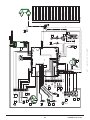
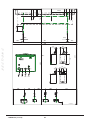
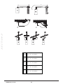
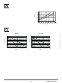
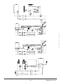
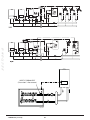
1
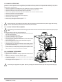
To be kept by the user
November 2013
Sirius two WH
90 & 110 kW
Instruction manual for users and fitters
Working towards
a cleaner future
heating specialists
Dear Customer,
Our company is confident our new product will meet all your requirements. Buying one of our products guarantees all your expectations: good performance combined with simple and rational use.
Please do not put this booklet away without reading it first: it contains useful information for the correct and efficient use of your
product.
Our company declares that these products are marked
following Directives:
in compliance with the essential requirements of the
- Gas Directive 2009/142/EC
- Efficiency Directive 92/42/EEC
- Electromagnetic Compatibility Directive 2004/108/EC
U s e r & I n s t a l l e r ( e n )
- Low Voltage Directive 2006/95/EC
Our company, constantly striving to improve the products, reserves the right to modify the details given in this documentation
at any time and without notice. These Instructions are only meant to provide consumers with use information and under no
circumstance should they be construed as a contract with a third party.
CONTENT
1.
1.1
1.2
2.
3.
4.
5.
6.
7.
8.
9.
9.1
10.
10.1
10.2
11.
11.1
11.2
12.
12.1
12.2
12.3
13.
14.
15.
15.1
16.
17.
18.
18.1
18.2
18.3
18.4
19.
DESCRIPTION OF SYMBOLS ..........................................................................................................................................3
SAFETY WARNINGS..........................................................................................................................................................3
GENERAL PRECAUTIONS ...............................................................................................................................................4
ENERGY-SAVING TIPS......................................................................................................................................................4
COMMISSIONING THE BOILER........................................................................................................................................5
ADJUSTING THE CH AND DHW FLOW TEMPERATURE.................................................................................................5
OPERATING MODES.........................................................................................................................................................5
PROLONGED SHUTDOWN. FROST PROTECTION.........................................................................................................6
GAS CONVERSION............................................................................................................................................................6
FAULTS...............................................................................................................................................................................6
BOILER INFORMATION MENU .........................................................................................................................................6
FILLING THE SYSTEM.......................................................................................................................................................7
ROUTINE MAINTENANCE INSTRUCTIONS.....................................................................................................................7
SWITCHING OFF THE BOILER.........................................................................................................................................7
INSTRUCTIONS PRIOR TO INSTALLATION.....................................................................................................................8
INSTALLING THE BOILER..................................................................................................................................................8
BOILER PUMP....................................................................................................................................................................8
INSTALLING THE FLUES...................................................................................................................................................9
CONCENTRIC FLUES........................................................................................................................................................9
CASCADE FLUES...............................................................................................................................................................9
ELECTRICAL CONNECTIONS...........................................................................................................................................10
CONNECTING THE ROOM THERMOSTAT.......................................................................................................................11
ACCESSORIES NOT INCLUDED IN THE SUPPLY...........................................................................................................11
SETTING PARAMETERS USING THE REMOTE CONTROL............................................................................................11
OUTDOOR SYSTEM MANAGEMENT MODULES.............................................................................................................13
SPECIAL FUNCTIONS........................................................................................................................................................14
SYSTEM AIR EXTRACTION FUNCTION...........................................................................................................................14
COMMISSIONING FUNCTION...........................................................................................................................................14
CHIMNEY SWEEP MODE..................................................................................................................................................14
FAULTS THAT CANNOT BE RESET BY THE USER..........................................................................................................14
PARAMETER SETTINGS...................................................................................................................................................14
GAS VALVE COMMISSIONING..........................................................................................................................................16
GAS CONVERSION............................................................................................................................................................16
ADJUSTMENT AND SAFETY DEVICES............................................................................................................................17
PUMP CAPACITY/ HEAD....................................................................................................................................................17
ANNUAL SERVICING.........................................................................................................................................................18
CLEAN THE HEAT EXCHANGER......................................................................................................................................18
CHECKING THE BURNER.................................................................................................................................................18
CLEANING THE CONDENSATE TRAP..............................................................................................................................19
COMBUSTION PARAMETERS...........................................................................................................................................19
TECHNICAL SPECIFICATIONS..........................................................................................................................................20
7108686.02 (1-11/12)
2
DESCRIPTION OF SYMBOLS
WARNING
Risk of damage to or malfunction of the appliance. Pay special attention to the warnings concerning danger to people. DANGER OF BURNS
Wait for the appliance to cool down before working on the parts exposed to heat.
DANGER - HIGH VOLTAGE
Live components - electrocution hazard.
DANGER OF FREEZING
Possible formation of ice due to low temperatures.
IMPORTANT INFORMATION
Information to read with particular care as it is useful for the correct operation of the boiler.
GENERIC PROHIBITION
It is forbidden to do/use the things indicated alongside the symbol.
SAFETY WARNINGS
SMELL OF GAS
•
•
•
•
Switch off the boiler.
Do not activate any electrical device (such as switching on the light).
Put out any naked flames and open the windows.
Call an Authorised Service Engineer.
SMELL OF COMBUSTION FUMES
• Switch off the boiler.
• Open all the doors and windows to ventilate the room.
• Call an Authorised Service Engineer.
FLAMMABLE MATERIAL
Do not use and/or store highly flammable material (thinners, paper, etc.) near the boiler.
SERVICING AND CLEANING THE BOILER
Switch off the boiler before working on it.
The appliance is not intended to be used by persons with reduced physical, sensory or mental capacities, or who lack experience or knowledge, unless, through the mediation of a person responsible for their safety, they have had the benefit of
supervision or of instructions on the use of the appliance.
3
7108686.02 (1-11/12)
U s e r & I n s t a l l e r ( e n )
GENERAL PRECAUTIONS
This boiler has been designed to heat water to a temperature lower than boiling point at atmospheric pressure. It must be connected to a central heating system and to a domestic hot water supply system according to its performance and power output. Before
having the boiler installed by a qualified service engineer, make sure the following operations are performed:
• Make sure that the boiler is adjusted to use the type of gas delivered by the gas supply. To do this, check the markings on the
packaging and the rating plate on the appliance.
• Make sure that the flue terminal draft is appropriate, that the terminal is not obstructed and that no exhaust gases from other
appliances are expelled through the same flue duct, unless the latter has been specially designed to collect exhaust gas from
more than one appliance, in compliance with current laws and regulations.
• Make sure that, if the boiler is connected to existing flue ducts, these have been thoroughly cleaned as residual products of
combustion may detach from the walls during operation and obstruct the flow of fumes.
• The use of a chimney liner is required for condensing boiler.
• To ensure correct operation and maintain the warranty, observe the following precautions:
1. DHW circuit
1.1 If the water is harder than 15 °F (1 °F = 10 mg calcium carbonate per litre of water), install a polyphosphate dispenser or an
equivalent treatment system, compliant with current regulations.
1.2 Thoroughly flush the system after installation of the appliance and before use.
1.3 The materials used for the DHW circuit must comply with Directive 98/83/EC.
2. Heating circuit
U s e r & I n s t a l l e r ( e n )
2.1 New system: Before installing the boiler, the system must be cleaned and flushed to eliminate residual thread-cutting swarf,
solder and any solvents, using suitable off-the-shelf non-acid and non-alkaline products that do not damage metal, plastic and
rubber parts. To protect the system from scale, use inhibitors such as SENTINEL X100 and FERNOX protector for heating circuits.
Use these products in strict compliance with the manufacturers’ instructions.
2.2 Existing system: Before installing the boiler, drain the system and clean it to remove sludge and contaminants, using suitable
proprietary products. Recommended cleaning products are: SENTINEL X300 or X400 and FERNOX regenerator for heating circuits. Use these products in strict compliance with the manufacturers’ instructions. Remember that the presence of foreign bodies
in the heating system can adversely affect boiler operation (e.g. overheating and excessive noise of the heat exchanger).
Initial lighting of the boiler must be carried out by an authorised Service Engineer who must first ensure that:
• The rated data correspond to the supply (electricity, water and gas) data.
• That the installation complies with current regulations.
• The appliance is correctly connected to the power supply and earthed.
IMPORTANT INFORMATION : DO NOT FIRE THE BOILER COMMISSIONING IF USED ON LPG (G31)
The appliance must be installed in a ventilated boiler room pursuant to current regulations (appliances with heating capacity
> 40 kW).
Failure to observe the above will render the warranty null and void. The names of the authorised Service Centres are indicated in the attached sheet. Prior to commissioning, remove the protective plastic coating from the boiler. Do not use any tools
or abrasive detergents to do this as you may damage the painted surfaces.
Do not leave any packaging (plastic bags, polystyrene, etc.) within the reach of children as they are a potential source of danger.
ENERGY-SAVING TIPS
Adjustment in the heating mode
Adjust the boiler flow temperature depending on the kind of system. For systems with radiators, set a maximum heating water flow
temperature of approximately 60°C, and increase this value if the required room temperature is not reached. For systems with
radiant floor panels, do not exceed the temperature indicated by the system designer. Use the External Sensor and/or Control
Panel to automatically adjust the flow temperature to atmospheric conditions or the indoor temperature. This ensures that no more
heat than that effectively necessary is produced. Adjust the room temperature without overheating the rooms. Every extra degree
centigrade means consuming approximately 6% more energy. Also room ambient temperature depending on how the rooms are
used. For example, the bedroom or the least used rooms can be heated to a lower temperature. Use the programmable timer and
set the night-time room temperature at approximately 5°C lower than that during the day. There is no appreciable saving to be
achieved by setting it any lower. Only in case of a prolonged absence, such as a holiday, should the temperature setpoint be lowered. Do not cover radiators as this prevents the air from circulating correctly. Do not leave the windows partially open to ventilate
the rooms but open them completely for a short period.
Domestic hot water
Setting the domestic hot water at the required temperature without mixing it with cold water saves a lot of money. Additional heating wastes energy and creates additional scale. Recommended minimum storage temperature of 60°C to reduce the Legionella
risk.
7108686.02 (1-11/12)
4
1. COMMISSIONING THE BOILER
To light the boiler correctly, proceed as follows:
•
•
•
•
Check that the system pressure is correct (section 6);
Power the boiler;
Open the gas tap;
Select the required heating mode (section 1.2).
During initial ignition, the burner may not ignite (causing the boiler to shut down) until any air in the gas pipes is vented.
In this case, repeat the ignition procedure until gas reaches the burner. To reset boiler operation, press
for at least 2
seconds.
Key to BUTTONS
DHW temperature adjustment
(+ to increase the temperature and – to decrease it)
Heating water temperature adjustment
(+ to increase the temperature and – to decrease it)
Boiler operating information
Operating mode:
DHW – DHW & Heating – Heating Only
Key to SYMBOLS
Off: heating and DHW disabled
(only boiler frost protection is active)
Burner lit
Fault preventing the burner from lighting
DHW operating mode enabled
Boiler/system water pressure low
Heating mode enabled
Technical Service Centre call-in
Programming menu
Manually resettable fault (
Boiler information menu
)
Fault in progress
Set unit of measurement (SI/US)
1.1 ADJUSTING THE CH AND DHW FLOW TEMPERATURE
Press
and respectively to adjust the CH and DHW flow temperature (if an external storage tank is fitted). When the
burner is lit, the display shows the symbol .
HEATING: while the boiler is operating in the heating mode, the display shows the flashing symbol
temperature (°C).
When connected to an Outdoor Sensor,
and the heating delivery
will indirectly adjust the room temperature (factory setting 20°C).
DHW: connect an external storage tank to produce domestic hot water. While the boiler is operating in the DHW mode, the display
shows the flashing symbol
and the heating flow temperature (°C).
1.2 OPERATING MODES
SYMBOL
DISPLAYED
OPERATING MODE
DHW
DHW & HEATING
To enable the appliance in DHW - Heating or Heating only press
and choose one of the three available modes.
repeatedly
To disable the boiler operating modes whilst keeping the frost function enabled,
press . Just the symbol appears on the display (with the boiler not blocked).
HEATING ONLY
5
7108686.02 (1-11/12)
U S E R S e c t i o n ( e n )
Off – Reset – Exit menu/functions
2. PROLONGED SHUTDOWN. FROST PROTECTION
Do not drain the whole system as filling up with water again could cause unnecessary and harmful scale to build up inside the
boiler and the heating elements. If the boiler is not used during winter and is therefore exposed to the danger of frost, add some
specific anti-freeze to the water in the system (e.g.: propylene glycol coupled with corrosion and scale inhibitors). The electronic
boiler management system includes a “frost protection” function for the heating system which, when delivery temperature falls
below 5°C, lights the burner until a delivery temperature of 30°C is reached.
The function is operative if: the boiler is electrically powered, there is gas, system pressure is normal and the boiler is not
blocked.
3. GAS CONVERSION
The boilers can operate both on natural gas (G20) and LPG (G31) . All gas conversions must be made by the AUTHORISED
TECHNICAL SERVICE CENTRE.
4. FAULTS
The faults shown on the display are identified with the symbol plete list of faults, see the following table.
and a number (fault code). For a com-
U S E R S e c t i o n ( e n )
If appears on the display the fault must be RESET by the user.
To RESET the boiler, press . If faults are displayed frequently, call the Authorised Service Engineer.
Description of fault
10
20
28
40
Description of fault
128
130
132
133
No flame during normal operation
151
Boiler board internal fault
153
Hardware reset button pressed more than 10 seconds
Address conflict between control units
160
Fan fault
109
Air in boiler circuit (temporary fault)
164
Flow pressure switch faulty
110
Safety thermostat tripped due to over temperature.
(pump probably blocked or air in heating circuit)
384
Parasite flame (internal error)
50
83
84
Outdoor temperature sensor faulty
NTC flow sensor faulty
NTC fumes sensor faulty
NTC return sensor faulty
NTC domestic hot water sensor faulty
(only for heating-only model with storage tank)
Communication problem between boiler board and
control unit. Probable short circuit on wiring.
Fumes NTC tripped due to over temperature
Gas pressure switch Safety shutdown.
Ignition failure (4 attempts)
111
Safety thermostat tripped due to overtemperature.
385
Input voltage too low
117
Pressure in hydraulic circuit too high
386
Fan speed threshold not reached
118
Pressure in hydraulic circuit too low
430
125
No circulation safety trip
(control performed via a temperature sensor)
432
No circulation safety trip
(control performed via pressure sensor)
No functional hearth or safety thermostat tripped due to over
temperature (E110)
In the event of a fault, the display backlighting indicates the error code. 5 reset attempts can be performed after which the
boiler
shuts down. Wait 15 minutes before attempting to reset the boiler again.
5. BOILER INFORMATION MENU
Press
to display the information indicated in the following table. Press
Description
00
01
02
03
04
05
06
07
08
10
Description
11
12
13
14
15
16
17
18
19
20
SW Diagnostic Code
Heating flow temperature
Outdoor temperature (if the outdoor sensor is fitted)
External storage tank temperature (fitted models)
Storage tank temperature (fitted models)
Water pressure in heating system
Heating return temperature
Flue sensor temperature
Not used
Zone 1 heating flow temperature
7108686.02 (1-11/12)
to exit.
6
Ion current
Burner working hours
Zone 2 heating flow temperature
Zone 1 heating mode
Zone 2 heating mode
DHW circuit operating mode
Boiler operating mode
Solar plant operating mode
Manufacturer information
Manufacturer information
6. FILLING THE SYSTEM
The pressure displayed on the pressure gauge has to be between 1 - 1.5 bar, with the system cold. If it is lower, turn the system
filling tap installed by the fitter.
IMPORTANT: open the tap very slowly in order to vent the air.
The
boiler is fitted with a hydraulic pressure switch which prevents the boiler from working if there is no water.
If pressure drops occur frequently (monthy basis), have the system checked by the AUTHORISED TECHNICAL SERVICE
CENTRE.
7. ROUTINE MAINTENANCE INSTRUCTIONS
To keep the boiler efficient and safe, have it checked by the Authorised Service Centre at the end of every 12 months.
Careful servicing ensures economical operation of the system.
8. SWITCHING OFF THE BOILER
To turn off the boiler, disconnect the electric power supply using the two-pole switch. In the “Off” operating mode off but the electrical circuits remain powered and the frost protection function remains active.
the boiler stays
7
7108686.02 (1-11/12)
U S E R S e c t i o n ( e n )
INSTRUCTIONS PRIOR TO INSTALLATION
The following notes and instructions are addressed to installers to allow them to carry out trouble-free installation. Instructions for
igniting and using the boiler are contained in the “Instructions for Users” section. The installation must satisfy the requirements of
BS and EN standards and local by-laws and technical regulations.
Moreover, the installation technician must be qualified to install heating appliances. Additionally, bear in mind the following:
• The boiler can be used with any kind of convector plate, radiator or thermoconvector. Design the system sections as usual,
though, bearing in mind the available capacity-head at the plate (see annex “SECTION” E at the end of this manual).
• Initial ignition of the boiler must be carried out by the Authorised Service Engineer.
Failure to observe the above will render the warranty null and void.
When supplied, the boiler is not fitted with the following components: EXPANSION VESSEL - SYSTEM FILLING TAP HYDRAULIC SEPARATOR. These must be mounted by the fitter.
Do
not leave any packaging (plastic bags, polystyrene, etc.) within the reach of children as they are a potential source of danger.
I N S T A L L E R S e c t i o n ( e n )
9. INSTALLING THE BOILER
The template outline is shown in annex “SECTION” C at the end of this manual.
After deciding the exact location of the boiler, fix the template to the wall. Connect the system to the gas and water inlets present
on the lower bar of the template. Make sure the rear part of the boiler (back) is as parallel as possible to the wall (otherwise, shim
the lower part). Fit two G1”1/4 taps (flow and return) on the central heating circuit; these taps make it possible to carry out important operations on the system without draining it completely. Fit a hydraulic separator, sized according to maximum boiler and
system pressure, downline from the hydraulic connectors of the boiler. If you are either installing the boiler on an existing system
installing a new system, as well as the above, fit a strainer under the boiler on the system return line in order to collect any deposits
and scale circulating in the system after flushing. After fixing the boiler to the template, connect the flue and air ducts, supplied as
accessories, as described in the following sections. Connect the siphon to a drain trap, making sure the slope is continuous. Avoid
horizontal stretches. The boiler is electronically fitted out for connection to an external storage tank.
Take special care when filling the heating system. In particular, open any thermostat valves in the system, ensure the water
enters slowly in order to prevent the formation of air inside the primary circuit until operating pressure is reached. Lastly,
vent any radiators in the system. POTTERTON COMMERCIAL declines all liability for damage deriving from the presence of
air bubbles in the primary exchanger due to the incorrect or imprecise observance of the above.
Tighten
the boiler water connections with care (maximum tightening torque 30 Nm).
9.1 BOILER PUMP
The boiler is supplied without the circulation pump. This component must be installed on the heating return to allow water to circulate between the boiler and the low loss header and can be purchased off the shelf or supplied by POTTERTON COMMERCIAL
as an accessory (modulating pump).
• In the first case the pump is installed on the heating return union near the boiler. To size it correctly see the Flow/Pressure
drops chart at the end of the manual in annex “SECTION” E (Size the pump in accordance to the ÐT of the system design.
• In the second case the pump is installed directly on the boiler removing the pipe on the internal circuit (first remove the
front casing). For hydraulic performance data, see the Flow/Head charts at the end of the manual in annex “SECTION” E.
The water in the system is circulated by the relative pumps, see annex “SECTION” E. Check that the flow of the water circulating
in the boiler is not less than the value indicated in the following table.
Model
Minimum flow rate (l/h)
Operating flow rate (l/h) with POTTERTON
COMMERCIAL low loss header
WH 90
2000
4200
WH 110
2250
4600
7108686.02 (1-11/12)
8
10.INSTALLING THE FLUES
The boiler is easy and flexible to install thanks to the extensive range of available accessories, as described below. The boiler has been designed for connection to a vertical or
horizontal concentric flue.
WARNINGS
C13, C33 The terminals for separate flues must be fitted in accordance with the BS standard and the Clean Air Act 1993. Detailed instructions are provided with the individual
accessories.
For optimal installation, the accessories supplied by the manufacturer should
be
used.
TABLE 1A
∆P (Pa)
If the flue and air ducts installed are not supply by POTTERTON
COMMERCIAL, make sure they are certitied for the type of use and
have a maximum pressure drop as indicated in the table to the side.
320
WH 110
370
To optimise operating safety, make sure the flues are firmly fixed to the wall with suitable brackets for every 1 metre of flue..
Make
sure there is a minimum downward slope of 5 cm per metre of duct towards the boiler.
SOME OUTLET FLUE INSTALLATION EXAMPLES AND THEIR RELATIVE MAXIMUM LENGTHS ARE SHOWN IN ANNEX “SECTION”
D AT THE END OF THIS MANUAL.
10.1 CONCENTRIC FLUES
This type of flue is used to discharge exhaust fumes and draw
combustion air both outside the building. The 87° concentric
bend allows the boiler to be connected to a flue-air in any direction as it can be rotated by 360° It can also be used as a
supplementary curve combined with a concentric flue or a 45°
bend.
If fumes are discharged outside the building, the flue-air must
protrude at least 200 mm from the wall to allow an aluminium
weathering surround to be fitted and sealed to avoid water infiltrations.
• The 87° bend reduces the total flue length by 1 metre.
• The 45° bend reduces the total flue length by 0.5 metres.
• The first 87° bend is not included when calculating the maximum available length.
10.2 CASCADE FLUES
This type of flue evacuates the products of combustion of more than one boiler in a cascade connection through a shared flue
header. The header may only be used to connect the boilers to the flue.
BOILER
MODEL
MAXIMUM NUMBER OF BOILERS
IN A CASCADE CONNECTION
Ø160 mm
Ø200 mm
(250 kW Max)
(500 kW Max)
WH 90
2
WH 110
2
PARAMETER P60(a)
Minimum power rpm
G20
G31
5
1450
1650
4
1500
1500
In this outlet typology, a flue no-return valve, Ø 80/110 mm, must be fitted to each boiler. Change the parameter P60(a) as
shown
in table following the procedure described in chapter 14.
The flue header size must be calculated by a qualified technician during the system design stage, as required by current regulations.
9
7108686.02 (1-11/12)
I N S T A L L E R S e c t i o n ( e n )
WH 90
11.ELECTRICAL CONNECTIONS
This machine is only electrically safe if it is correctly connected to an efficient earth system in compliance with current safety regulations. Connect the boiler to a 230V single-phase earthed power supply using the supplied three core cable, observing correct
Live-Neutral polarity.
Use a double-pole switch with a contact separation of at least 3 mm.
When replacing the power supply cable, fit a harmonised 3x0,75 mm2 cable with a maximum diameter of 8 mm. To access the
terminal block, remove the front boiler panel (fixed with two screws at the bottom), turn the control box downwards and access
terminal blocks M1, M2, M3, used for the electrical connections, after removing the protective cover. The 3.15 A fast-blowing fuses
are incorporated in the power supply terminal block (to check and/or replace the fuse, pull out the black fuse carrier).
SEE WIRING DIAGRAM IN ANNEX “SECTION” B AT THE END OF THIS MANUAL
Make sure that the overall rated power input of the accessories connected to the appliance is less than 2A. If it is higher, install
a
relay between the accessories and the electronic board.
I N S T A L L E R S e c t i o n ( e n )
The connections in terminal blocks M1- M3 are high voltage (230 V). Before making connections, make sure the appliance is
disconnected from the power supply. Check the input polarity on terminal block M1: L (LINE) - N (NEUTRAL).
TERMINAL BLOCK M1
(L) = Live (brown)
(N) = Neutral (light blue).
= Earth (yellow-green).
(1) (2) = contact for Room Thermostat.
Put back the jumper on terminals 1-2 of boiler terminal block
M1 if the room thermostat is not used or if the Remote Control
is installed.
TERMINAL BLOCK M2
Terminals 1 (back-lighting) - 2 (earth) - 3 (+12V): connection to the
Remote Control (low voltage) supplied as an accessory.
Terminals 4 - 5 (common): Outdoor temperature sensor (supplied
as an accessory)
Terminals 6 - 5 (common): 2nd Auxiliary Sensor (sensors for solar
plant, cascade system, zone system, etc.).
Terminals 7 - 5 (common): 1st Auxiliary Sensor (sensors for solar plant, cascade system, zone system, etc.).
Terminals 9-10: storage tank sensor connection.
Terminal 8: not used.
TERMINAL BLOCK M3
Terminal 1-2: boiler pump supply 230 V AC (max 1 Amp)
Terminal 3-4: not used
Terminal 5-6: PWM signal of the modulating pump
Terminal 7-8: not used
Terminal 9 - 10: Domestic Hot Water tank pump (max 1 Amp)
Terminal 11 - 12: Heating System pump (device connected downstream of the hydraulic separator - max 1 Amp)
If
the appliance is connected to an underfloor system, install a limit thermostat to prevent the circuit from overheating.
Use
the relative cable grommets at the bottom of the boiler to thread the cables through to the terminal blocks.
7108686.02 (1-11/12)
10
11.1 CONNECTING THE ROOM THERMOSTAT
The connections in terminal block M1 are in high voltage (230 V). Before making connections, make sure the appliance is
disconnected from the power supply. Check the polarity: L (LIVE) - N (NEUTRAL).
To connect the Room Thermostat to the boiler, proceed as described below:
• Switch off the boiler;
• Access the terminal block M1;
• Remove the jumper from the ends of contacts 1-2 and connect the wires of the volt free Room Thermostat;
• Switch on the boiler and make sure the Room Thermostat
works correctly.
Min. 200 mm
1500mm
11.2 ACCESSORIES NOT INCLUDED IN THE
SUPPLY
The wire (1) from the boiler terminal block M2 powers the display backlighting (12 V). It is not necessary to connect this wire to
make
the Remote Control work.
To operate the boiler with the Remote Control mounted on the wall, purchase accessory A supplied with the base A1. Also see
the mounting and operation instructions supplied with the kit A. Proceed as follows:
•
•
•
•
•
•
Switch off the boiler.
Pass the three wires from the boiler terminal block M2 through the hole in the base A1 to apply to the wall.
Connect wires 1-2-3 of the boiler terminal block M2 to terminals (1)-(2)-(3) of the base terminal block A1 respectively.
Fix the base A1 to the wall using the expansion grips and screws supplied with the accessory.
Apply the Control Panel A to the base fixed to the wall, taking care not to apply excessive force.
Power the boiler making sure that the Remote Control lights up.
A
A - A1
A1
B
A1
B1
A
A1
B1
B
A
Control Panel
A1
Base for wall-mounted Control Panel
B
Led interface accessory
B1
Base for Led interface accessory
(1)
Display backlighting +12V
(2)
Earth connection
A
(3)
Power input/Signal +12V
Use the Remote Control to set the programmable timer for heating and DHW. See the instructions supplied with the accessory.
SETTING PARAMETERS USING THE REMOTE CONTROL
SYMBOLS FOR REMOTE CONTROL
Turn knob B
Display shows
Press knob B
Press button A and knob B together
Press button A or C
Press buttons A and C together
11
7108686.02 (1-11/12)
I N S T A L L E R S e c t i o n ( e n )
11.2.1 REMOTE CONTROL
KEY TO FIGURE MENU
1
2
Enduser
Commissioning
3
4
Engineer
OEM
ALL MODIFIED PARAMETERS SHOULD BE NOTED
DOWN IN THE TABLE AT THE END OF THIS MANUAL
(page 31).
The following procedure is used to access the four boiler programming menus:
• from the main menu C.
•
A and C (hold down for approx. 6 seconds) B menu 1-2-3-4 (see figure to side and key).
• C to go back one menu at a time to the main menu.
When the Control Panel is wall-mounted enable the Room Temperature Sensor and flow temperature modulation as follows:
I N S T A L L E R S e c t i o n ( e n )
A) ROOM SENSOR
• Access menu 2.
•
B Operator unit B to confirm.
•
B programme row 40 (Used as) B.
•
B (anti-clockwise) Room unit 1 B to confirm (the room sensor is now active).
•
C to return to the previous menu then B Configuration B.
•
B
programme row 5977 (Function input H5) then
B to confirm.
•
B
None
B to confirm.
B) FLOW TEMPERATURE MODULATION
To set flow temperature modulation, disable parameter 742 (HC1). Proceed as follows:
• Access menu 2.
•
B Temps / mode CH1 B to confirm B • B (anti-clockwise) “---” then B to confirm.
742 (Flow temp setpoint room stat)
B to confirm. If, when turning the knob B on the main menu, the display shows the boiler flow temperature instead of the ambient temperature,
parameter 742 has not been set correctly.
After every system configuration (e.g.: solar combination, connection an external storage tank, etc.) perform the following procedure to update the boiler board to the new configuration:
• Access menu 2 as indicated at the beginning of this section.
•
B Configuration B B programme row 6200 then •
B Yes then
B to confirm.
B.
ZONE SYSTEM WITH INSTALLATION OF THE REMOTE CONTROL
The electrical connection and the adjustments required to manage a system divided into zones with use of the Remote Control
differs according on the accessories connected to the boiler. To install and configure, see the instructions of the Expansion Module supplied as an accessory.
ADJUSTING THE TEMPERATURE OF THE HIGH TEMPERATURE HEATING SYSTEM
To avoid frequent starting and stopping, raise the minimum temperature setpoint of the boiler in the heating mode by setting parameters 740, to not less than 25°C, using the procedure described in point B.
TEMPERATURE ADJUSTMENT ON LOW TEMPERATURE HEATING SYSTEM
For a low temperature system (such as underfloor heating), reduce the maximum CH temperature setpoint on the boiler by setting
parameter 741 (point B) to a value not greater than 55°C.
11.2.2 OUTDOOR SENSOR
The outdoor sensor must be installed on an external wall of the
building that is to be heated (see figure SECTION F), considering the following instructions:
• work on a wall facing north/north-east (avoid direct sunshine;
• do not install on walls subject to the formation of damp or
moss (identify the presence of thermal bridges;
• do not install near fans, steam outlets or chimneys (it is important to avoid the external temperature controlled by the
probe being infl uenced by external agents;
• ensure that the thickness of the wall used is suitable for
obtaining good heat insulation (do not fi x it to metal walls).
7108686.02 (1-11/12)
12
To connect this accessory, see figure to side (terminals 4-5) and the instructions supplied with the sensor.
With the outdoor sensor connected, press
buttons on the control panel to move the set climate curve Kt in parallel (see
annex “SECTION” F and parameter P03 in the table in section 14). To increase room temperature press +, to decrease press -.
SETTING THE “Kt” CLIMATE CURVE
To set the required kt climate curve, proceed as follows:
• Access the menu as described in section 14.
• Select parameter P03.
• Select the climate curve from among those available, see the curve chart in annex “SECTION” F at the end of this manual
(the preset curve is 1.5).
KEY TO CURVE CHART Kt - “SECTION” F
Flow temp
Outside temp
Connect the boiler pump to terminals 1-2 of the M3 terminal block as described in section 3. If the pump is a modulating pump
connect the PWM signal to the termials 5-6 of the M3 terminal block.
11.2.4 HEATING SYSTEM PUMP
Install the system pump downline from the hydraulic separator. Choose the pump according to the required system capacity/head
characteristics (see annex “SECTION” E).
11.2.5 DOMESTIC HOT WATER CYLINDER
The boiler can be electrically connected to an external storage tank. A diagram of the hydraulic connection of the external storage
tank is shown in annex “SECTION” G. Connect the storage tank pump to terminals 4-5 of the M3 terminal block (see annex “SECTION” B). Install the storage boiler downline from the hydraulic separator. Use the sensor supplied as an accessory and connect
it to terminals 9-10 of terminal block M2 (see annex “SECTION” B). Make sure that the exchange capacity of the domestic hot
water coil is appropriate for the power of the boiler.
OUTDOOR SYSTEM MANAGEMENT MODULES
The boiler can independently manage up to three heating circuits by using external accessories such as room units, remote
controls and external modules (AVS 75). The boiler electronics also comprises a wide range of functions for personalising and
managing various system types. To assure correct system operation, a number (from 1 to 3) must be assigned to each accessory
in order to allow the boiler board to recognise it. Consequently, carefully read the instructions provided with the accessories.
11.2.6 MIXED ZONES (“SECTION” G)
A mixed zone can be managed using the AVS75 external module, supplied as an accessory. This accessory can manage: a zone
pump, a mixing valve, a temperature sensor, a limit thermostat and a room thermostat. To connect the components and adjust the
system read the manual provided with the accessory.
11.2.7 BOILERS IN A CASCADE CONNECTION (“SECTION” G)
The AVS75 external unit, supplied as an accessory, is used to manage a heating system with up to 16 boilers connected in a
cascade arrangement and a possible separate storage tank providing domestic hot water. This accessory, connected to one of
the cascade boilers, can directly control the circuit components up to a maximum of 3 independent relay outlets, 2 temperature
sensors, 1 high voltage limit thermostat connector and one 1 control input (e.g.: room thermostat). The system also requires an
OCI 345 interface on each boiler comprising in the cascade arrangement.
THE HYDRAULIC DIAGRAMS OF THE CASES DESCRIBED CAN BE FOUND IN ANNEX “SECTION” G AT THE END OF THIS
MANUAL
13
7108686.02 (1-11/12)
I N S T A L L E R S e c t i o n ( e n )
11.2.3 BOILER PUMP
ALARM (LOCKOUT)
SIGNAL LAMP 230V
11.2.8 AGU 2.550
230 V
(Boiler M1)
~
Use the AGU 2.550 , already installed in the boiler, to send information from the boiler
as described below to a BMS panel.
STATUS (RUN)
SIGNAL LAMP 230V
CG_2241
I N S T A L L E R S e c t i o n ( e n )
ELECTRICAL CONNECTION
X1 (L-N)
Power supply (230V 50Hz AC) connected to the boiler terminal
block M1 (C+M)
X1 (QX21)
Not used
X1 (QX22-N)
Boiler OPERATION (light on = run)
X1 (QX23-N)
Boiler ALARM (light on = lockout)
X2 (H2-M)
INPUT Electrical Signal 0÷10 V
3
0÷10 V
Input Signal
12.SPECIAL FUNCTIONS
12.1 SYSTEM AIR EXTRACTION FUNCTION
This function is used to facilitate the elimination of the air inside the heating circuit when the boiler is first installed or after maintenance when the water is drained from the primary circuit and re-filled.
To enable the system air extraction function press buttons
together for 6 seconds. When the function is active, On appears on the display for a few seconds, followed by programme
row 312.
The electronic board will activate a pump on/off cycle lasting 10 minutes. The function will automatically stop at the end of the
cycle. To manually exit this function, press the above buttons together for 6 seconds once again.
12.2 COMMISSIONING FUNCTION
To commissioning the gas valve, proceed as follows:
• Press buttons
and together for at least 6 seconds. When the function is enabled, the displays shows “On” for a few
seconds followed by programme row “304” alternated with the % of boiler power.
• Press
to gradually adjust power (sensitivity 1%) 100% for high fire and 0% for low fire.
• To exit press both buttons together for at least 6 seconds, as described in point one.
Press
to display the instantaneous flow temperature for 15 seconds.
12.3 CHIMNEY SWEEP MODE
When this function is enabled, the boiler generates maximum heating power. To enable the function, proceed as follows:
• press
together for 6 seconds. The display shows “303” alternated with the power output of the boiler.
• Press
and to adjust boiler power 1=minimum, 2=maximum DHW, 3=maximum heating.
• To exit press both buttons together for at least 6 seconds, as described in point one.
13.FAULTS THAT CANNOT BE RESET BY THE USER
In case of FAULTS that cannot be reset by pressing
(such as E151 or exceeding 5 manual
RESET attempts by the user) RESET the board by pressing the black button ( R) located under
the rubber cap (symbol
) of the front control panel (figure to side).
14.PARAMETER SETTINGS
To programme the parameters of the boiler electronic board, proceed as follows:
• Press
together and hold them down for 6 seconds until programme row “P02” appears on the display alternated with the set value (°C);
• Press
and hold down for 6 seconds until “On” appears on the display. Release the button and “P01” appears on the display;
• Press
to scroll the list of parameters;
• Press
, the value of the selected parameter begins flashing, press
to change the value;
• Press
to confirm the value or press
to exit without saving.
Further information concerning the parameters listed in the following table are supplied together with the required accessories.
7108686.02 (1-11/12)
14
Factory
setting
(b)
ZONE 1 HEATING PARAMETERS (main zone)
P01
P02
P03
P04
P05
P06
P07
P08
P09
P10
700
712
720
721
726
740
741
742
750
834
P11
P12
P13
P14
P15
P16
P17
P18
P19
P20
P21
1000
1010
1012
1020
1021
1026
1040
1041
1042
1050
1134
P22
1620
P23
1640
P24
1641
P25
P26
1663
5470
P27
P28
P29
P30
P31
2243
2217
2250
2441
2455
P34
P35
P36
P37
P38
P39
3810
3811
3830
3850
5050
5051
*Operating mode (0=Frost Protection, 1=Timed, 3=T.comfort)
*Reduced ambient temperature
*“Kt” curve slope
*“Kt” curve drift
*“Kt” curve adaptation (0=off)
Flow temperature setpoint (minimum value)
Flow temperature setpoint (maximum value)
*Enable modulating temperature if set = “---”
*Room influence (“---” = disabled)
*Opening/Closing speed of mix valve
ZONE2 HEATING PARAMETERS (with accessory Expansion Unit)
*Operating mode (0= Frost Protection, 1=Timed, 3=T.comfort)
*Comfort room temperature
*Reduced room temperature
*“Kt” curve slope
*“Kt” curve drift
*“Kt” curve adaptation (0=off)
Flow temperature setpoint
Flow temperature setpoint (maximum value)
*Enable modulating temperature if set = “---” (flow temp. setpoint if P63=0)
*Room influence (“---” = disabled)
*Opening/Closing speed of mix valve
DHW PARAMETERS
Operating mode in DHW (with Remote Control)
0=always enabled, 1=according to hourly heating programme,
2= according to hourly DHW programme.
Anti-legionella function Disabled
0=disabled, 1=periodic (depending on P24)
Periodic anti-legionella function enable (only if P23 =1)
1=daily, 2..6=intervals of 2..6 days, 7=once a week
Circulation temperature setpoint (additional DHW pump)
Preheating time for DHW circuit (1=10’ -- 144=1440’)
BOILER PARAMETERS
Minimum boiler off time
Frost Protection setpoint
Pump post-circulation time
Max. fan speed (heating)
Minimum boiler off differential
SOLAR PLANT PARAMETERS (with accessory Expansion Unit)
Temperature - on differential
Temperature - off differential
Collector start function (“---” = disabled)
Solar panel manifold overheating protection (“---“ = disabled)
DHW charging temperature max
Maximum temperature of storage tank
P40
P41
P42
P43
P44
P45
P46
P47
P48
P49
P50
P51
P52
5700
5710
5715
5730
5890
5931
5932
5977
6020
6024
6046
6097
6110
CONFIGURATION
Not used (Do NOT change this parameter)
Zone 1 heating circuit (1=enabled)
Zone 2 heating circuit (1=enabled)
DHW sensor (1=Tank sensor, 2=Thermostat, 3=instantaneous sensor)
Not used (Do NOT change this parameter)
*BX2 sensor input (first auxiliary sensor – section 11)
*BX3 sensor input (second auxiliary sensor – section 11)
*Input H5 (multifunction input – 18=Room thermostat)
*Configuration of accessory Expansion Unit
Function input EX21 module 1 (configuration of HC Safety Thermostat)
Function input H2 module 1 (multifunction input)
Sensor type collector (1= NTC, 2= Pt 1000)
Building time constant
P53
P54
P55
P56
6220
6600
6601
6640
Software version
LPB device address
LPB segment address
Clock time source
°C
°C
°C
°C
%
S
°C
°C
°C
°C
°C
°C
%
s
3
16
1,5
0
1
25
80
80
50
180
3
20
16
1,5
0
1
25
80
80
50
180
-
0
0
2
-
0
0
1
-
7
1
7
°C
min
min
°C
min
rpm
°C
°C
°C
min
°C
°C
°C
45
0
3
5
3
xxx
10
8
4
----65
90
8
0
0
-20
0
0
0
0
0
5
30
8
8
80
144
20
20
240
8000
20
40
40
60
350
95
95
--1
0
1
33
0
0
18
0
0
0
2
15
--0
0
1
0
0
0
0
0
0
0
1
0
--1
1
3
43
19
19
32
7
1
58
2
50
0
1
0
0
99
16
14
3
h
-
15
Minimum Maximum
---
0
4
0,1
- 4,5
0
8
25
25
1
30
0
4
4
0,1
- 4,5
0
8
25
25
1
30
3
35
4
4,5
1
80
80
80
100
873
3
35
35
4
4,5
1
80
80
80
100
873
7108686.02 (1-11/12)
I N S T A L L E R S e c t i o n ( e n )
(a)
P57
P58
P59
P60
P61
P62
P63
P64
MAINTENANCE
Time after maintenance
View/Hide secondary fault internal code (0=no)
BURNER CONTROL
9512
Required ignition speed
9524
Required minimum operating speed (low speed)
9529
Required maximum operating speed (high speed)
BOILER CONTROL PANEL PARAMETERS
Unit of measurement (1=bar, °C – 2=PSI, °F)
Control panel operation: (1=central, 0=local)
Software version
7045
6704
month
-
xxx
1
0
0
240
1
rpm
rpm
rpm
-
xxx
xxx
xxx
1
1
xx
0
0
0
1
0
0
8000
8000
8000
2
1
999
* see “Accessories not included in supply”
xx: the value depends on the software version
xxx : the value depends on the type of boiler
(a): parameters read on the front boiler panel (fixed control panel)
(b): parameters read on the Remote Control
To commission the gas valve, enable the commission function as described in section 12.2
and carry out the following operations:
1) Commissioning MAXIMUM heat output.
Check that the measured on the flue duct, with the boiler operating at maximum heat
capacity, matches that indicated in table 2 (allowed tolerance +/- 0.5%). If it does not, turn the
adjustment screw (V) on the gas valve. Turn the screw clockwise to decrease the level of and anti-clockwise to increase it (allowed tolerance +/- 0.2%).
2) Commissioning REDUCED heat output
Check that the measured on the flue duct, with the boiler operating at minimum heat
capacity, matches that indicated in table 2 (allowed tolerance +/- 0.5%). If it does not, remove
the threaded brass cap on the gas valve and turn the adjustment screw (K). Turn the screw
clockwise to increase the level of and anticlockwise to decrease it (allowed tolerance
+/- 0.2%).
I N S T A L L E R S e c t i o n ( e n )
15.GAS VALVE COMMISSIONING
15.1 GAS CONVERSION
When converting from natural gas to propane (LPG), before calibrating
the gas valve as described above, replace the venturi assembly ( B) as
indicated in the figure. To achieve this, dismount the gas pipe (threaded nut G1”) and remove the three screws securing the flange. Afterwards,
make sure there are no gas leaks. Modify the parameters (fan rpm) as indicated
in table 2 following the procedure described in section 14.
To simplify commissioning of the gas valve, set the “commissioning
function” directly on the boiler control panel as described in section
12.2.
For cascade ducts, change the parameter P60(a) increasing the number of fan revolutions (rpm) by 200 (see table in chapter 10.2).
TABLE 2
PARAMETERS - rpm
Boiler
model
P60 (a)
P30 – P61 (a)
P59 (a)
Min. power
Max. power
Ignition power
VENTURI
Ø (mm)
GAS NOZZLES
Ø (mm)
G20
G31
G20
G31
G20
G31
G20-G31
G20
G31
WH 90
1250
1500
6500
6200
2400
2400
34
5.6 (n°2)
WH 110
1300
1300
6900
6700
2500
3000
38
6.4 (n°2)
G20
G31
4.5 (n°2)
*8,5 *9,9
*9,0
*10
5.0 (n°2)
*9,0
*9,2
*10
value read on the boiler front panel display to multiply x 10 (e.g.: 160 corresponds to 1600 rpm)
7108686.02 (1-11/12)
16
G20
CO2 Max
(%)
G31
* CO2 with cover closed. Without cover (chamber open) the value is less than 0.2%.
(a)
CO2 Min
(%)
*9,5
Max. CO
(ppm)
G20/G31
< 250
16.ADJUSTMENT AND SAFETY DEVICES
The boiler has been designed in full compliance with European reference standards and in particular is equipped with the following:
• Limit thermostat
Thanks to a sensor placed on the CH flow line, this thermostat interrupts the flow of gas to the burner if the water in the primary
circuit overheats. Under such conditions the boiler is blocked and only after the fault has been eliminated can it be ignited again
by pressing
.
It is forbidden to disable this safety device.
• NTC flue sensor
This device is positioned on the fumes duct. The electronic board stops gas from flowing to the burner in case of over heating.
Press
to re-establish normal operating conditions.
The above reset operation is only possible if the temperature is less than 90°C.
It is forbidden to disable this safety device
The flame sensing electrode guarantees safety of operation in case of gas failure or incomplete ignition of the main burner. In
these conditions, the boiler blocks. Press
to re-establish normal operating conditions.
• Hydraulic pressure switch
This device allows the main burner to be ignited only if system pressure is higher than 1 bar.
• Pump post-circulation
The electronically-controlled pump post-circulation function lasts 3 minutes and is enabled, in the heating mode, if the ambient
thermostat causes the main burner to go out.
• Antifreeze device
The electronic boiler management system includes an “antifreeze” function for the heating and DHW systems which, when flow
temperature falls below 5°C, operates the burner until a flow temperature of 30°C is reached. This function is enabled when the
boiler is switched on, the gas supply is open and the system is correctly pressurised.
• Pump anti-block function
If no heat demand is received in the heating and/or DHW modes for 24 consecutive hours, the pumps will automatically start and
operate for 10 seconds.
• Hydraulic safety valve (heating circuit)
This device is set to 4 bar and is used for the heating circuit. Connect the safety valve to a drain trap. Do not use it to drain the
heating circuit.
• Heating pump pre-circulation
In case of a heat demand in the heating mode, the appliance can pre-circulate the pump before the burner is ignited. This precirculation phase last from a few seconds to a few minutes, depending on the operating temperature and installation conditions.
• Gas pressure switch
This device enables the main burner only to be switched on if the gas pressure is over 12 mbar.
The functions performed by the adjustment and safety devices are only operative if the boiler is switched on.
17.PUMP CAPACITY/ HEAD
The hydraulic pump, supplied as an accessory kit from POTTERTON COMMERCIAL, is a modulating pump. The purpose of the
pump is to circulate the water between the boiler and the hydraulic separator.
KEY TO PUMP CHARTS - SECTION E
Q
H
RATE OF FLOW
HEAD
THE
PUMP FLOW / HEAD CHARTS CAN BE CONSULTED IN ANNEX “SECTION” E AT THE END OF THE MANUAL.
17
7108686.02 (1-11/12)
I N S T A L L E R S e c t i o n ( e n )
• Flame ionisation detector
18.ANNUAL SERVICING
The service must be performed only by qualified and competent staff in accordance with the Gas safety, Installation and use regulations. In UK this person need to be approved by the Health and Safety Executive. To optimise boiler efficiency, carry out the
following at the annual service:
•
•
•
•
•
•
•
•
•
•
Check the appearance and airtightness of the gaskets of the gas and combustion circuits;
Check the state and correct position of the ignition and flame-sensing electrodes;
Check the state of the burner and make sure it is firmly fixed;
Check for any impurities inside the combustion chamber. Use a vacuum cleaner to do this;
Check the gas valve is correctly calibrated;
Check the pressure of the heating system;
Check the pressure of the expansion vessel (system);
Check the fan works correctly;
Make sure the flue and air ducts are unobstructed;
Check for any blockages inside the siphon.
I N S T A L L E R S e c t i o n ( e n )
Before commencing any maintenance operations, make sure the boiler is disconnected from the power supply. After servicing,
reset the original operating parameters of the boiler if they were changed.
18.1 CLEAN THE HEAT EXCHANGER
Before starting to disassemble the heat exchanger protect the electronic box and all the electrical components against sprayed
water.
Proceed as follows to dismount the Heat Exchanger:
• Isolate the unit from the electrical mains (disconnect the boiler from
the main elecrical supply).
• Cut off the gas supply to the boiler.
• Close the maintenance taps on the boiler.
• Remove the front cover trom the boiler.
• Unscrew the screw securing the electrical box, lower it and protect
it from splashing water.
• Remove the Ignition electrode and the flame detection probe.
• Remove the Assembly Fan-Mixer
• Clean the pipes (1) of the heat exchanger using regular vinegar.
Flush with water. The water flows out of the heat exchanger through the water condense trap.
• Wait for approx. 20 minutes than flush away the dirt particles with a
powerfuf water jet. Avoid pointing the water jet directly at the insulating surface (2) on the back of the heat exchanger.
18.2 CHECKING THE BURNER
The burner needs no cleaning.
• Check the burner surface for damage, replace the burner if necessary.
• Check the positioning of the flame detection probe.
• Verify that the distance of the ignition electrode is within tolerance
as shown in the figure.
• Check that the burner surface insulation in the burner flange it is
not damaged otherwise replace it.
Connect the gas supply with a new gasket. Open the gas supply and check the boiler for gas leaks using a leak testing spay.
7108686.02 (1-11/12)
18
2
1
BURNER
IGNITION
ELECTRODE
7,5 ±1 for model WH 90
5,0 ±1 for model WH 110
BURNER SURFACE
INSULATION
FLAME DETECTION
PROBE
90
WH 10
del WH 1
l
mo
for mode
±1
10 ±1 for
7,5
CG_2190
1
51
_0
CR
18.3 CLEANING THE CONDENSATE TRAP
Unscrew the lower section of the water condense trap.
• Clean the bottom of the trap by flushing it out with water.
• Fill the lower section with water until about 10 mm below the upper
edge.
• Fasten the lower section onto the condense trap again.
Do not operate the boiler with empty condense trap to avoid risk
of poisoning through the gas combustions.
CONDENSATE DRAIN
(Uncrew to clean it)
CR_0510
18.4 COMBUSTION PARAMETERS
To measure combustion efficiency and the emissions of the products of combustion, the boiler is
fitted with two dedicated test points. One connection point is connected to the flue gas discharge
circuit ( A), and allows monitoring of the quality of the combustion products and the combustion
efficiency. The other is connected to the combustion air intake circuit ( B), allowing checking of
any recycling of the combustion products in case of coaxial pipelines. The following parameters
can be measured at the connection point on the flue gas circuit:
• temperature of the combustion products;
• oxygen ( ) or carbon dioxide (
) concentration;
• carbon monoxide ( ) concentration.
A
B
C
90
The temperature of the combustion air must be measured on the test point located on the air intake flue (B) by inserting the measurement sensor by about 90 mm (C).
To
enable the “ CHIMNEY SWEEP MODE” consult section 12.3.
19
7108686.02 (1-11/12)
I N S T A L L E R S e c t i o n ( e n )
19.TECHNICAL SPECIFICATIONS
I N S T A L L E R S e c t i o n ( e n )
Model: SIRIUS TWO
WH 90
WH 110
Category
II2H3P
Gas used Natural Gas and LPG
-
G20 - G31
Rated heat input
kW
87,4
104,9
Reduced heat input (G20)
Reduced heat input (G31)
kW
9,7
11,7
kW
12,5
11,7
Rated heat output 80/60 °C
kW
85,0
102,0
Rated heat output 50/30 °C
kW
91,8
110,2
Reduced heat output
80/60 °C (G20)
kW
9,4
11,4
Reduced heat output
80/60 ° C (G31)
kW
12,2
11,4
Reduced heat output
50/30 °C (G20)
kW
10,2
12,3
Reduced heat output
50/30 ° C (G31)
kW
13,1
12,3
Net Rated efficiency (92/42/EEC) 80/60 °C
%
97,3
97,2
Net Rated efficiency
%
105,5
105,1
Efficiency 30% Pn (92/42/EEC)
%
107,5
107,4
Max. pressure of water in heating circuit
bar
Min. pressure of water in heating circuit
bar
50/30 °C
Capacity of boiler circuit (volume of water)
Temperature range in heating circuit
4
0,5
l
9
10
°C
25÷80
-
C13 - C33 - B23
Concentric flue duct diameter
mm
110/160
Diameter of separate outlets
mm
110/110
Max. mass flow rate of flue (G20)
kg/s
0,040
Min. mass flow rate of flue (G20)
kg/s
0,005
Flue Types
Max. temperature of fumes
°C
NOx Class 5 (EN 297 - EN 483)
0,047
0,005
70
mg/kWh
39,5
24,7
Natural gas supply pressure 2H (G20)
mbar
Propane gas supply pressure 3P (G31)
mbar
37
Power supply voltage
V
230
Power supply frequency
Hz
50
Rated power supply (Without Pump)
W
130
165
Rated power supply (With Pump)
W
275
320
Rated power supply
W
275
320
Net weight (empty)
kg
83
Dimensions
CE Certificate
93
- height
mm
952
- width
mm
600
- depth
mm
584
-
IPX5D
Protection-limit against humidity (EN 60529)
Noise level at 1 metre
20
dB(A)
< 50
Nr
0085CM0128
CONSUMPTION AT HEAT INPUT Qmax and Qmin
Qmax (G20) - 2H
m3/h
9,25
11,10
Qmin (G20) - 2H
m3/h
1,03
1,24
Qmax (G31) - 3P
kg/h
6,60
7,92
Qmin (G31) - 3P
kg/h
0,97
0,91
7108686.02 (1-11/12)
20
I N S T A L L E R S e c t i o n ( e n )
7108686.02 (1-11/12)
21
5
4
6
1
2
3
4
5
6
7
8
9
3
7
S E C T I O N A
8
9
10
2
11
12
1
13
19
14
15
16
A
7108686.02 (1-11/12)
B
18
C
17
D
22
10
11
12
13
14
15
16
17
18
19
A
B
C
D
Fan
Air/gas blend manifold
Primary exchanger
Coaxial flue connector
Flue sensor
Automatic air vent
Ignition electrode
NTC water heating sensor
(flow and return)
Safety overflow temperature
thermostat
Flame detection electrode
Spark generator
Venturi
Pump
Hydraulic Safety valve
Boiler drain tap
Pressure gauge
Hydraulic Pressure Sensor
Gas pressure switch
Gas valve
Trap condensate drain
Gas inlet connection
Heating flow connection
Heating return connection
7108686.02 (1-11/12)
5
6
7
23
10
11
9
1
2
3
C
C
B
V
N
R
B
L
N
2
1
4
M
12
R
M1
C
8
R
10
9
8
7
6
5
4
3
2
1
M
C
G/V
M
N
20
21
13
M2
V
V
Y
P
N
M
B
N
R
12
11
10
9
8
7
6
5
4
3
2
1
M3
X20
N
N R
C
C M
X 14
X41
C
M
X1
X70
X42
X2
X23
X60
C
C
C
V
G/V
M
N
14
G/V
a b
15
G/V
G/V
G/V
G/V
G/V
Auxiliary Sensor 1
16
17
G/V
G/V
G/V
G/V
V
C
M
19
G/V
18
Gas pressure switch
Red
Black
White
Grey
Yellow
Violet
G
Y
P
CR_0378
Green
V
B
G/V Yellow/Green
R
N
Brown
AGU 2.550
23
Blue
DHW tank pump
22
M
Heating circuit pump
21
V
C
Fan
20
N
M
Safety Thermostat 105°C
19
C C C M C M
N
Igniter
Gas valve
C
18
Ignition electrode
16
R
C
Flame sensor electrode
15
Boiler pump
14
13
17
M
C
M
G/V
Auxiliary Sensor 2
DHW tank sensor
9
Fumes sensor
Water pressure switch
Heating return sensor
8
7
6
5
Heating flow sensor
Room Unit (RU)
4
230 V Power Supply
3
Fuses
2
1
Remote Control
X 12
X22
1
X40
R
Outdoor sensor
V N
C
C
R
R
B
B
N
R
15
X30
N
12
X 11
V
V
B
13
230 V
11
C
V
X50
X21
M
X50
1 2
ON
L
N
C
N
on
on
1 2
1 2
1 2
on
AGU2.5
N QX23 N QX22 N QX21
230 V
10
Y
L
H2 M BX21 M BX22 U+
X2
X1
X1
L
N
M
X10
P
22
S E C T I O N B
23
50
70
72
245,5
Ø8
Ø8
419
90,5
90,5
600
600
S E C T I O N C
112
354,5
245,5
Ø8
809
952
112
102
G1-1/2
245,5
G1-1/2"
100
100
100
G1
7108686.02 (1-11/12)
170
G1-1/2
24
198
G1-1/2
30
G 1"
184,5
7109986-01
951
584
S E C T I O N C
25
7108686.02 (1-11/12)
S E C T I O N D
7108686.02 (1-11/12)
A B
Lmax = 10 m - Ø 110/160 mm
CD
Lmax = 9 m - Ø 110/160 mm
EF
Lmax = 10 m - Ø 110/160 mm
G
Lmax = 8 m - Ø 110/160 mm
H
Lmax = 9 m - Ø 110/160 mm
26
3
H (mH2O)
4
4
3
H (mH2O)
8
8
7
7
6
6
2
2
1
1
0
0
00
48
00
44
00
40
00
36
00
32
00
28
00
24
00
20
00
16
0
0
12
0
80
7108686.02 (1-11/12)
27
0
40
0
00
44
00
40
00
36
00
32
00
28
00
24
00
20
00
16
0
0
12
0
80
0
40
0
Q (l/h)
Q (l/h)
WH 110
2,5
2
1,5
H (mH2O)
3
S E C T I O N E
5
5
WH 110
WH 90
WH 90
3,5
4
1
0,5
0
Q (l/h)
S E C T I O N F
WEATHER COMPENSATION CURVE GRAPHS
QAC34
7108686.02 (1-11/12)
28
AGU 2.550
S E C T I O N G
CR_0349
AVS 75
CR_0349
29
7108686.02 (1-11/12)
S E C T I O N G
SAFETY THERMOSTAT
(Tmax=50°C - free contact)
CG_2482
7108686.02 (1-11/12)
30
MODIFIED PARAMETERS
Nr
NOTE
VALUE

31
7108686.02 (1-11/12)
Publication Date: NOV2013
RS 33961
Baxi Commercial
Wood Lane, Erdington,
Birmingham B24 9QP
Sales:
Technical:
0845 070 1056 0845 070 1057
Email: [email protected]
www.pottertoncommercial.co.uk
heating specialists