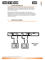
1
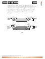
<
CONTENTS
>
PRINT
GUIDES
CONTENTS (ENGLISH)
1
INTRODUCTION
Page No
2
2
3.1
UNPACKING
MECHANICAL
3
4
3.2
INITIAL SETTINGS
4
4
CONNECTIONS
4.1 Input Connections
5
5
4.2 Output Connections
5
CONTROLS
7
8
5.1 Mode Switch
8
5.2 Level Controls
8
5.3 Limiters
8
5.4 Phase Correction
9
6
7
SYSTEM CONFIGURATION
CONNECTION DIAGRAMS
10
10
8
9
WARRANTY
TECHNICAL SPECIFICATIONS
13
14
MARTIN AUDIO
L O N D O N
The Martin Experience
All material © 2007. Martin Audio Ltd. Subject to change without notice.
Martin Audio – MX5 System Controller
>
PRINT
GUIDES
This equipment conforms to the requirements of the
EMC Directive 89/336/EEC, amended by 92/31/EEC
and 93/68/EEC and the requirements of the Low
Voltage Directive 73/23/EEC, amended by 93/68/EEC.
Standards Applied
EMC
Emission
Immunity
Electrical Safety
1
EN55103-1:1996
EN55103-2:1996
EN60065:1998
INTRODUCTION
Thank you for purchasing a Martin Audio MX5 system controller.
The MX5 is the latest and most advanced analogue Martin Audio
loudspeaker management system and can be configured to optimise the
performance of any combination of Martin Audio high end loudspeakers.
The MX5 includes the following features:
1. Single plug-in board system-specific.
2. Accurate level controls with ± 6dB of gain.
3. All star grounding with separate buses for signal 0V, output 0V and digital
0V giving extreme low noise capabilities.
4. Individual voltage regulation of analogue display and output sections.
5. Enhanced output drive capabilities and balancing.
6. Absolute phase adjustment and band edge phase trim.
7. Ten sections of signal delay all pass filters for driver offset compensation.
8. Program dependant attack times on each limiter section.
9. Configurable as a ‘1 in - 4 out’ line level distribution amplifier with all level
and limiter functions operable.
10. LED peak programme meters on each band.
All material © 2007. Martin Audio Ltd. Subject to change without notice.
2
Martin Audio – MX5 System Controller
ENGLISH
<
CONTENTS
2
>
PRINT
GUIDES
UNPACKING
Each Martin MX5 controller is built to the highest standard and thoroughly
inspected before it leaves the factory. After unpacking the unit, examine it
carefully for any signs of transit damage and inform your dealer if any such
damage is found. It is suggested that you retain the original packaging so
that the unit can be repacked at a future date if necessary.
Please note that Martin Audio and its distributors cannot accept
responsibility for damage to any returned product through the use of nonapproved packaging.
All material © 2007. Martin Audio Ltd. Subject to change without notice.
3
Martin Audio – MX5 System Controller
ENGLISH
<
CONTENTS
<
3.1
>
PRINT
GUIDES
MECHANICAL
The MX5 is housed in an all steel 1U 19" rack case. In permanent
installations, the MX5 should be rack mounted using the four holes in the
front panel. Additional support may be required for heavy duty road use.
IMPORTANT: THE MAINS LEAD SUPPLIED MUST BE CONNECTED
AS BELOW:
GREEN/YELLOW
BLUE
BROWN
-
EARTH
NEUTRAL
LIVE
Mains voltage tolerance ± 10% on each setting.
Fuses type T semi-delay
100-120V 500mA(L)
220-240V 250mA(L)
WARNING: The MX5 controller must always be operated with the
mains safety connected.
This equipment must be earthed.
!
CAUTION
RISK OF ELECTRIC SHOCK
DO NOT OPEN
DO NOT EXPOSE TO RAIN
OR MOISTURE
It should not be necessary to remove any protective earth or signal cable
shield connections.
3.2
INITIAL SETTINGS
MX5 Controllers are supplied with the adjustments set as follows:
Mains voltage
Ground switch
Limiter threshold
Plug-in board
240V
On
2V setting
System-specific
All material © 2007. Martin Audio Ltd. Subject to change without notice.
4
Martin Audio – MX5 System Controller
ENGLISH
CONTENTS
4
>
PRINT
GUIDES
CONNECTIONS
Power is supplied to the unit via an IEC connector with integral fuse
holder/voltage selector. To change to a different mains voltage remove the
rectangular fuse cap, rotate and replace so that the correct voltage is
indicated by the arrow on the body of the receptacle.
The earth terminal on the IEC connector is permanently connected to the
chassis.
The electronic reference 0V is taken to chassis via the rear panel signal
ground switch. This inserts a ground lift resistor when switched to off.
The inputs and outputs of the MX5 are electronically balanced, pin 2 being
designated + (hot). Because both inputs and outputs are balanced either
pin can be assigned as + (hot) provided the convention is maintained
through the controller.
4.1
Input Connections
The MX5 inputs are on female XLR type connectors and are electronically
balanced. Pin 1 is normally open circuit but may be linked to sig 0V or
chassis earth by inserting a hard wire link on the PCB (see Fig 1). The
signal is always applied between Pin 2 (hot +) and Pin 3 (cold -).
/
\
/\
link for pin 1 chassis/earth
link for pin 1 signal 0V
No link for pin 1 open circuit
Fig 1.
All material © 2007. Martin Audio Ltd. Subject to change without notice.
5
Martin Audio – MX5 System Controller
ENGLISH
<
CONTENTS
<
>
PRINT
GUIDES
Always use 2-core + screen ‘balanced’ type signal leads, even for
unbalanced circuits. The screen should be regarded as separate from the
signal return, even if they are connected together at one end of the line.
For either balanced or unbalanced operation, always connect the signal
between Pins 2 and 3. The input cable shield should be derived from
equipment which is sourcing the input provided that normal safety
requirements are met (ie the mains earth is correctly connected)
(See Fig 2).
Chassis
Grounded
Shield
Source
MX5
Input
1
2
2
3
3
1
Ground
Lift
Resistor
MX5
Input
Source
Signal
Grounded
Shield
1
2
2
3
1
3
Fig 2.
All material © 2007. Martin Audio Ltd. Subject to change without notice.
6
Martin Audio – MX5 System Controller
Ground
Lift
Resistor
ENGLISH
CONTENTS
<
4.2
>
PRINT
GUIDES
Output Connections
The MX5 outputs are electronically balanced auto compensating via male
XLR type connectors. Pin 1 is the (ground) connection and the signal
appears between Pins 2 and 3.
Always use 2-core + screen ‘balanced’ type signal leads, even for
unbalanced circuits. The screen should be regarded as separate from the
signal return, even if they are connected together at one end of the line.
This is to keep the screen a true screen so that no signal return currents
flow through it which can induce signals in adjacent cables.
For unbalanced use, having decided which pin is ‘hot’ (see above), connect
the ‘cold’ pin and (Pin 1) together. The signal ground switch should be
placed in the Lift position at the MX5 outputs which permit the amplifier to
be locally grounded (as required for safety reasons) without causing a hum
loop. If the signal is merely taken between either Pin 2 or 3 and Pin 1, a
level loss and signal degradation will occur.
For balanced operation, the screen should be connected to ground at the
amplifier end. To eliminate ground current loops, it can be lifted at the MX5
output, provided normal safety requirements have been met (ie the mains
earths are correctly connected-See Fig 3).
Signal
Grounded
Shield
MX5 Output
1
Amplifier Input
2
2
3
Amplifier Input
MX5 Output
Chassis
Grounded
Shield
1
1
3
2
2
3
1
3
Fig 3.
All material © 2007. Martin Audio Ltd. Subject to change without notice.
7
Martin Audio – MX5 System Controller
ENGLISH
CONTENTS
>
PRINT
5
CONTROLS
5.1
Mode Switch
GUIDES
This is mounted internally on the plug-in board and allows the unit when
appropriate, to be switched from 3-way to 4-way operation.
In 3-way mode the (‘mid’) output will function up to the upper bandpass
filter or as defined by system parameters, band 4 (’high’) remains available
and may be used for driving additional VHF units in ‘overlap’ mode.
5.2
Level Controls
Each frequency bands level can be adjusted over a 12dB range from
-6dB to +6dB relative to its nominal level to allow the user to precisely
balance each level with respect to each other.
5.3
Limiters
Each output is fitted with a limiter which provides momentary gain reduction
when the signal level exceeds a preset threshold value. A red LED
indicates the onset of limiting.
Threshold settings for the limiters may be adjusted by first removing the
MX5 top cover (two screws on each side) to gain access to the 16 way
switches which are located on the main motherboard. Setting the limiter
threshold automatically sets the range of the LED display which will indicate
dB’s below threshold.
Threshold values corresponding to the switch positions are printed on the
main motherboard reproduced here for your information.
0
1
0.2 0.4
2
3
0.5 0.7
4
5
0.9 1.1
6
1.3
7
8
9
A
1.4 1.6 1.8 2.0
B
2.2
C
2.3
D
2.5
E
F
2.7 2.9
Each channel limiter sets a maximum drive level from the MX5, which in
turn sets the maximum continuous voltage that the amplifier can present to
its load.
The plug-in top board has pre-set time constants that optimise the limiters
for each frequency band.
The limiters in the MX5 may be used to control the average continuous
power applied to the loudspeakers, if power amplifiers with a higher
maximum power rating than that recommended are used. (See Amplifier
section) Alternatively, if the loudspeakers selected will handle the full rated
power, or if maximum system headroom is required, the limiters may be set
to prevent the amplifiers being driven into hard clipping.
All material © 2007. Martin Audio Ltd. Subject to change without notice.
8
Martin Audio – MX5 System Controller
ENGLISH
<
CONTENTS
<
>
PRINT
GUIDES
WARNING: Care should be taken to avoid amplifier clipping. It is important
to understand that a low power amplifier driven into clipping is more likely
to damage a loudspeaker than a higher power amplifier used within its
ratings. This is because music signals have a high peak to average "crest"
factor. When an amplifier is severely overdriven, its output waveform is
clipped (its peaks are squared off) – reducing the crest factor. In extreme
cases, the waveform can approach that of a square wave. An amplifier is
normally capable of producing far more power under these conditions than
its normal undistorted rated power output. Correct setting of the limiters will
automatically avoid amplifier clipping and prevent damage occurring to the
loudspeakers.
Each limiter may be completely defeated, if desired, by setting a jumper
located on the main mother board (J1-J4). If another MX5 is to be driven
from any of the output channels (eg where one MX5 splits the signal
between sub-bass loudspeakers and the main system crossovers), then the
limiters should be defeated on those channels to prevent them from
operating before the limiters in the following units.
JUMPER
POSITION
LIMITER
BAND 1
J1
BAND 2
J2
BAND 3
J3
BAND 4
J4
RIGHT
LEFT
RIGHT
LEFT
RIGHT
LEFT
RIGHT
LEFT
ON
OFF
ON
OFF
ON
OFF
ON
OFF
5.4
Phase Correction
Although the outputs from the MX5 are normally in phase at the crossover
points, the acoustic outputs from the associated drive units may not be.
Correct adjustment can compensate for the phase characteristics of the
drive units and associated protective filter circuitry.
Phase alignment on an MX5 ‘system’ board is accurately set for the
speaker system for which it is supplied, and is not adjustable.
All material © 2007. Martin Audio Ltd. Subject to change without notice.
9
Martin Audio – MX5 System Controller
ENGLISH
CONTENTS
>
6
PRINT
ENGLISH
<
CONTENTS
GUIDES
SYSTEM CONFIGURATION
The MX5 where used in conjunction with a plug-in board becomes a
dedicated system controller. Depending on the plug-in system-specific
board, the MX5 is automatically configured either as a stereo 2-way or
mono 3/4 way controller.
Each plug-in board dictates a system-specific crossover function,
equalisation and, in some cases, group delay. User options include low
frequency EQ in/out (J1 and J2), 3/4 way operation (S2) and mono bass in
2-way stereo configurations. Where a particular option is not available it
will be hard wired out.
7
CONNECTION DIAGRAMS
LOW
0dB
-6
+6
LEFT
HIGH
0dB
HIGH
0dB
STEREO 2 WAY
LIMIT
0dB
LIMIT
0dB
-6
-6
-6
-12
MUTE
(SUB)
RIGHT
LIMIT
0dB
-6
-6
+6
-18
MUTE
LOW
0dB
LIMIT
0dB
-12
-6
+6
MUTE
MUTE
-12
-6
+6
-18
-18
MUTE
(LOW)
MUTE
MID
CONFIGURATION
POWER
-12
-18
MUTE
ON
MUTE
HIGH
MX5
SYSTEM
CONTROLLER
MONO 3/4 WAY
MX5 LE700
2 WAY
All material © 2007. Martin Audio Ltd. Subject to change without notice.
10
Martin Audio – MX5 System Controller
<
>
PRINT
LOW
0dB
LEFT
GUIDES
HIGH
0dB
+6
-6
RIGHT
HIGH
0dB
STEREO 2 WAY
LIMIT
0dB
LIMIT
0dB
-6
-6
-6
-12
-12
-12
+6
-6
+6
-6
MUTE
MUTE
(LOW)
(SUB)
+6
-6
-18
-18
MUTE
MUTE
CONFIGURATION
POWER
LIMIT
0dB
-6
-18
MUTE
LOW
0dB
LIMIT
0dB
-12
-18
MUTE
MUTE
HIGH
MID
ON
MUTE
MX5
SYSTEM
CONTROLLER
MONO 3/4 WAY
MX5 W8/W8S 4-WAY
LOW
0dB
-6
+6
LEFT
HIGH
0dB
HIGH
0dB
STEREO 2 WAY
LIMIT
0dB
LIMIT
0dB
-6
-6
-6
-12
MUTE
(SUB)
RIGHT
LIMIT
0dB
-6
-6
+6
-18
MUTE
LOW
0dB
LIMIT
0dB
-12
-6
+6
MUTE
(LOW)
-12
+6
-6
-18
-18
MUTE
MUTE
MUTE
-12
ON
MUTE
MONO 3/4 WAY
MX5 W8C/WSX 4-WAY
All material © 2007. Martin Audio Ltd. Subject to change without notice.
POWER
-18
MUTE
HIGH
MID
CONFIGURATION
11
Martin Audio – MX5 System Controller
MX5
SYSTEM
CONTROLLER
ENGLISH
CONTENTS
<
>
PRINT
LOW
0dB
LEFT
HIGH
0dB
RIGHT
HIGH
0dB
STEREO 2 WAY
LIMIT
0dB
LIMIT
0dB
LIMIT
0dB
-6
-6
-6
-6
-12
+6
-6
-18
MUTE
LOW
0dB
LIMIT
0dB
-12
+6
-6
GUIDES
-12
+6
-6
MUTE
MUTE
MUTE
(LOW)
(SUB)
POWER
-12
+6
-6
-18
-18
MUTE
CONFIGURATION
-18
MUTE
MUTE
HIGH
MID
ON
MUTE
MX5
SYSTEM
CONTROLLER
MONO 3/4 WAY
MX5 W8/W8S 3-WAY
LOW
0dB
-6
+6
LEFT
HIGH
0dB
HIGH
0dB
STEREO 2 WAY
LIMIT
0dB
LIMIT
0dB
-6
-6
-6
-12
MUTE
(SUB)
RIGHT
LIMIT
0dB
-6
-6
+6
-18
MUTE
LOW
0dB
LIMIT
0dB
-12
-6
+6
MUTE
MUTE
(LOW)
-12
+6
-6
-18
-18
MUTE
MUTE
-12
MUTE
ON
MUTE
MONO 3/4 WAY
MX5 W8C/WSX 3-WAY
All material © 2007. Martin Audio Ltd. Subject to change without notice.
POWER
-18
HIGH
MID
CONFIGURATION
12
Martin Audio – MX5 System Controller
MX5
SYSTEM
CONTROLLER
ENGLISH
CONTENTS
8
>
PRINT
GUIDES
WARRANTY
Martin Audio MX5 System Controllers are warranted against manufacturing
defects in materials or craftsmanship over a period of 1 year from the date of
original purchase. During the warranty period Martin Audio will, at it's
discretion, either repair or replace products which prove to be defective
provided that the product is returned in its original packaging, shipping
prepaid, to an authorised Martin Audio service agent or distributor.
Martin Audio Ltd. cannot be held responsible for defects caused by
unauthorised modifications, improper use, negligence, exposure to inclement
weather conditions, act of God or accident, or any use of this product that is
not in accordance with the instructions provided by Martin Audio.
Martin Audio is not liable for consequential damages.
This warranty is exclusive and no other warranty is expressed or implied.
This warranty does not affect your statutory rights.
All material © 2007. Martin Audio Ltd. Subject to change without notice.
13
Martin Audio – MX5 System Controller
ENGLISH
<
CONTENTS
9
>
PRINT
GUIDES
TECHNICAL SPECIFICATIONS
MX5
INPUTS
2 Electronically Balanced
IMPEDANCE
CMRR
CONNECTORS
36K ohms (18K ohms per leg single ended)
67dB @ 10KHz
3 Pin female XLR
OUTPUTS
4 Electronically Balanced
SOURCE IMPEDANCE
MIN LOAD IMPEDANCE
MAX OUTPUT
CONNECTORS
47 ohms
500 ohms
+20dBu into 500 ohms limiter defeated
3 Pin Male XLR
FREQUENCY RESPONSE
-3dB @ 25 Hz 24dB/octave
-3dB @ 35KHz 12 dB/octave
(ultimately set by system parameters)
DISTORTION+NOISE
0.009% THD @ 2V output (limiters cancelled)
SIGNAL+NOISE/
NOISE RATIO
>97dB @ 2V output 20Hz – 20KHz quasi
peak o/c input
LIMITERS
Individual for each channel. With program
related attack times. Ratio 20:1. Threshold
range -12dBu to +12dBu in 16 steps
INDICATORS
2-way stereo, 3/4 way-mono LED’s. 10 section
LED PPM indicating signal level, threshold and
limit on each band
PROTECTION
Auto muting relays and soft start (4 seconds)
MAINS SUPPLY
IEC mains connector with integral fuse holder
MAINS VOLTAGE
Externally selectable on IEC inlet 100-120-220240V AC, 50/60Hz. Voltage tolerance on each
setting ±10%
MAINS FUSE
220-240V: -250mA Type ‘T’(L)
100-120V: -500mA Type ‘T’(L)
DIMENSIONS
(W) 482mm x (H) 44mm x (D) 211mm
(W) 19ins x (H) 1.75ins x (D) 8.3ins
WEIGHT
3.5kg (7.7 lbs)
SHIPPING DIMENSIONS
(W) 530mm x (H) 120mm x (D) 310mm
(W) 21ins x (H) 4.7ins x (D) 12.2ins
SHIPPING WEIGHT
4.1kg (9lbs)
Due to our policy of continuous product improvement all specifications are
subject to change without notice.
All material © 2007. Martin Audio Ltd. Subject to change without notice.
14
Martin Audio – MX5 System Controller
ENGLISH
<
CONTENTS
CONTENTS
<
>
PRINT
GUIDES
MX5 System Controller
Please Click here to
return to main menu
Please Click here to
visit our website
MARTIN AUDIO
L O N D O N
The Martin Experience
Century Point, Halifax Road, Cressex Business Park, High Wycombe, Buckinghamshire HP12 3SL, England.
Telephone: +44 (0)1494 535312 Facsimile: +44 (0)1494 438669
Web: www.martin-audio.com E-mail: [email protected]
All material © 2007. Martin Audio Ltd. Subject to change without notice.
CONTENTS
<
>
PRINT
GUIDES
MX5 System Controller
User’s Guide
ENGLISH
MARTIN AUDIO
L O N D O N
The Martin Experience
All material © 2007. Martin Audio Ltd. Subject to change without notice.