1
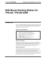
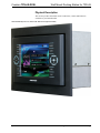
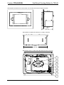
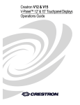
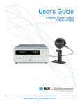
Crestron TPS-6X-DSW Wall Mount Docking Station for TPS-6X Operations & Installation Guide This document was prepared and written by the Technical Documentation department at: Crestron Electronics, Inc. 15 Volvo Drive Rockleigh, NJ 07647 1-888-CRESTRON Regulatory Compliance As of the date of manufacture, the TPS-6X-DSW has been tested and found to comply with specifications for CE marking and standards per EMC and Radiocommunications Compliance Labelling. Federal Communications Commission (FCC) Compliance Statement This device complies with part 15 of the FCC rules. Operation is subject to the following conditions: (1) this device may not cause harmful interference and (2) this device must accept any interference received, including interference that may cause undesired operation. CAUTION: Changes or modifications not expressly approved by the manufacturer responsible for compliance could void the user’s authority to operate the equipment. NOTE: This equipment has been tested and found to comply with the limits for a Class B digital device, pursuant to part 15 of the FCC rules. These limits are designed to provide reasonable protection against harmful interference in a residential installation. This equipment generates, uses and can radiate radio frequency energy and if not installed and used in accordance with the instructions, may cause harmful interference to radio communications. However, there is no guarantee that interference will not occur in a particular installation. If this equipment does cause harmful interference to radio or television reception, which can be determined by turning the equipment off and on, the user is encouraged to try to correct the interference by one or more of the following measures: Reorient or relocate the receiving antenna Increase separation between the equipment and the receiver Connect the equipment into an outlet on a circuit different from that to which the receiver is connected Consult the dealer or an experienced radio/TV technician for help Industry Canada (IC) Compliance Statement This Class B digital apparatus complies with Canadian ICES-003. Cet appareil numérique de la classe B est conforme à la norme NMB-003 du Canada. All brand names, product names and trademarks are the property of their respective owners. ©2010 Crestron Electronics, Inc. Crestron TPS-6X-DSW Wall Mount Docking Station for TPS-6X Contents Wall Mount Docking Station for TPS-6X: TPS-6X-DSW 1 Introduction ............................................................................................................................... 1 Features and Functions ................................................................................................ 1 Specifications .............................................................................................................. 2 Physical Description.................................................................................................... 3 Setup .......................................................................................................................................... 7 Network Wiring........................................................................................................... 7 Supplied Hardware ...................................................................................................... 7 Mounting Options........................................................................................................ 8 Installation ................................................................................................................... 8 Removal .................................................................................................................... 12 Hardware Hookup ..................................................................................................... 12 Operation ................................................................................................................................. 13 Docking the Touchpanel............................................................................................ 13 Undocking the Touchpanel........................................................................................ 13 Problem Solving ...................................................................................................................... 15 Troubleshooting......................................................................................................... 15 Check Network Wiring.............................................................................................. 16 Reference Documents................................................................................................ 17 Further Inquiries ........................................................................................................ 17 Future Updates .......................................................................................................... 18 Return and Warranty Policies .................................................................................................. 19 Merchandise Returns / Repair Service ...................................................................... 19 CRESTRON Limited Warranty................................................................................. 19 Operations & Installation Guide – DOC. 6708B Contents • i Crestron TPS-6X-DSW Wall Mount Docking Station for TPS-6X Wall Mount Docking Station for TPS-6X: TPS-6X-DSW Introduction The Crestron® TPS-6X-DSW Wall Mount Docking Station facilitates charging of the TPS-6X Isys® Wireless Touchpanel (sold separately) while simultaneously enabling wired touchpanel operation with full motion video capability. It is designed for installation in a flat, vertical wall structure. Features and Functions • • • • • • • • A stylish wall mount dock for the Isys® TPS-6X Provides a convenient battery charging solution Affords full-featured wall mount touchpanel operation Supports wired Ethernet or Cresnet® communications Enables balanced or unbalanced video input Powered by Cresnet Available in high gloss black or white or matte black Multiple wall mounting options available Stylish Convenience While docked, the touchpanel is partially recessed, providing a refined appearance and useful functionality while inhibiting unauthorized removal. By pressing a button or entering a passcode on the touchpanel, the mechanism gently extends the touchpanel outward, allowing it to be released for wireless use. A hardware key is also provided to release the touchpanel in the event of a power failure. Flexible Connectivity The TPS-6X-DSW provides both wired Ethernet and Cresnet® connectivity to the touchpanel. When the touchpanel is placed in the docking station, it switches automatically from RF wireless to fully wired operation if either Ethernet or Cresnet are connected. Without a wired Ethernet or Cresnet connection present, the touchpanel will continue to operate wirelessly while it charges. Power is drawn from the Cresnet network. A composite video input is also included to enable the display of full motion video on the touchpanel screen while docked. Operations & Installation Guide – DOC. 6708B Wall Mount Docking Station for TPS-6X: TPS-6X-DSW • 1 Wall Mount Docking Station for TPS-6X Crestron TPS-6X-DSW Vertical Mounting Options The TPS-6X-DSW is designed for easy flush mount installation in a flat, vertical wall structure. A variety of mounting accessories is offered for both pre- and post-construction applications. The TPS-6X-DSW is included with the TPS-6XWALL Isys 5.7” Wall Mount Wireless Touchpanel and is also available separately for use with any TPS-6X model. It is available in high gloss black or white or matte black finishes. Specifications Specifications for the TPS-6X-DSW are listed in the following table. TPS-6X-DSW Specifications SPECIFICATION Power Requirements DETAILS 43 Watts (1.8 Amps @ 24 Volts DC) with touchpanel docked; Power is drawn from Cresnet network Environmental Temperature 41º to 104º F (5º to 40º C) Humidity 10% to 90% RH (non-condensing) Heat Dissipation 147 BTU/Hr Enclosure Chassis Metal, flush mountable in a vertical wall structure (all mounting accessories sold separately) Faceplate Plastic, color matched to touchpanel Dimensions Height 6.83 in (174 mm) 7.11 in (181 mm) with bezel Width 9.35 in (238 mm) 9.70 in (247 mm) with bezel Depth 3.70 in (94 mm) 4.17 in (106 mm) with bezel 4.50 in (115 mm) with touchpanel docked Weight 5.2 lbs (2.4 kg) Available Models TPS-6X-DSW Wall Mount Docking Station for TPS-6X High Gloss Black TPS-6X-DSW-B-T Wall Mount Docking Station for TPS-6X, Matte Black TPS-6X-DSW-W-S Wall Mount Docking Station for TPS-6X, High Gloss White Available Accessories BB-6X-DSW Pre-Construction Wall Mount Back Box BBI-6X-DSW Wall Mount Back Box (International Version) MMK-6X-DSW Mud Ring PMK-6X-DSW Pre-Construction Wall Mount Kit TMK-6X-DSW Trim Ring WMKM-6X-DSW Post-Construction Wall Mount Kit with Mud Ring WMKT-6X-DSW Post-Construction Wall Mount Kit with Trim Ring 2 • Wall Mount Docking Station for TPS-6X: TPS-6X-DSW Operations & Installation Guide – DOC. 6708B Crestron TPS-6X-DSW Wall Mount Docking Station for TPS-6X Physical Description This section provides information on the connections, controls and indicators available on your TPS-6X-DSW. TPS-6X-DSW Physical View (Shown with TPS-6X Touchpanel Installed) Operations & Installation Guide – DOC. 6708B Wall Mount Docking Station for TPS-6X: TPS-6X-DSW • 3 Wall Mount Docking Station for TPS-6X Crestron TPS-6X-DSW TPS-6X-DSW Overall Dimensions (Front and Side Views) 9.35 in (238 mm) 8.00 in (204 mm) 6.35 in (162 mm) 5.98 in (152 mm) 6.83 in (174 mm) 3.70 in (94 mm) TPS-6X-DSW Overall Dimensions (Front and Side Views with Bezel Attached) 9.70 in (247 mm) 7.11 in 181 mm) 4.17 in (106 mm) 4 • Wall Mount Docking Station for TPS-6X: TPS-6X-DSW Operations & Installation Guide – DOC. 6708B Crestron TPS-6X-DSW Wall Mount Docking Station for TPS-6X TPS-6X-DSW Overall Dimensions (Front and Side Views with Bezel and TPS-6X Touchpanel Attached) 4.50 in (115 mm) TPS-6X-DSW Overall Dimensions (Bottom View with Bezel Attached) 8.89 in (226 mm) TPS-6X-DSW (Front View with Aesthetic Plate Removed to Show Connectors) 1 2 3 4 5 6 7 Operations & Installation Guide – DOC. 6708B Wall Mount Docking Station for TPS-6X: TPS-6X-DSW • 5 Wall Mount Docking Station for TPS-6X Crestron TPS-6X-DSW Connectors, Controls & Indicators # CONNECTORS1, CONTROLS & INDICATORS DESCRIPTION 1 TOUCHPANEL CONNECTOR (1) 10-pin connector for attaching touchpanel 2 LATCH RELEASE 3 OPEN (1) Miniature pushbutton, accessible when touchpanel is not docked, releases the docking mechanism to allow touchpanel to be docked 4 NET (1) 4-pin 3.5 mm detachable terminal block; Cresnet slave port, connects to Cresnet control network 24: Power (24 Volts DC) Y: Data Z: Data G: Ground 5 VID IN (UNBL)2 S V (1) 2-pin 3.5 mm detachable terminal block; Unbalanced composite video input; Input impedance: 75 Ω nominal; Input level: 1 Vp-p nominal, 1.5 Vp-p maximum; Maximum DC offset: ±2 Volts; Connects to any conventional coax video source 6 VID IN (BAL)2 (1) 3-pin 3.5 mm detachable terminal block; Balanced composite video input; Input impedance: 100 Ω nominal; Input level: 1 Vp-p nominal, 1.5 Vp-p maximum; Maximum DC offset: ±2 Volts; Connects to any Crestron CH CAT5 Video Out port via CresCAT® cable + - S 7 LAN3 Pin 1 Manual latch release (1) 8-wire RJ-45 female; 10 BASE-T/100BASE-TX Ethernet Port PIN SIGNAL PIN SIGNAL 1 2 3 4 TX + TX RX+ N/C 5 6 7 8 N/C RX N/C N/C 1. Interface connectors for NET, VID IN (BAL), and VID IN (UNBL) ports are provided with the unit. 2. Balanced and unbalanced video inputs are mutually exclusive. 3. To determine which is pin 1 on the cable, hold the cable so that the end of the eight pin modular plug is facing away from you, with the clip down and copper side up. Pin 1 is on the far left. 6 • Wall Mount Docking Station for TPS-6X: TPS-6X-DSW Operations & Installation Guide – DOC. 6708B Crestron TPS-6X-DSW Wall Mount Docking Station for TPS-6X Setup Network Wiring When wiring the Cresnet® and Ethernet network, consider the following: • Use Crestron Certified Wire. • Use Crestron power supplies for Crestron equipment. • Provide sufficient power to the system. CAUTION: Insufficient power can lead to unpredictable results or damage to the equipment. Please use the Crestron Power Calculator to help calculate how much power is needed for the system (www.crestron.com/calculators). Cresnet For networks with 20 or more devices, use a Cresnet Hub/Repeater (CNXHUB) to maintain signal quality. For more details, refer to “Check Network Wiring” which starts on page 16. Ethernet The TPS-6X-DSW can also use high-speed Ethernet for communications between the device and a control system, computer, digital media server and other IP-based devices. For information on connecting Ethernet devices in a Crestron system, refer to the latest version of the Crestron e-Control Reference Guide (Doc. 6052), which is available from the Crestron website (www.crestron.com/manuals). Supplied Hardware The hardware supplied with the TPS-6X-DSW is listed in the following table. Supplied Hardware for the TPS-6X-DSW DESCRIPTION PART NUMBER QTY 4504777 1 Assembly, Bezel, with IR, Wall Dock, Matte Black 4507641 1 Assembly, Bezel, with IR, Wall Dock, White3 4507241 1 1, 2 4505195 1 3 Metal Plate, Aesthetic, White 4507217 1 Screw, #04-40 x 3/16”, Steel, Flat, Phil, Black1, 2 2007145 4 Screw, #04-40 x 3/16”, Steel, Flat, Phil, Zinc3 2007150 4 Screw, #06-32 x 1 1/2”, Steel, Pan, Phil 2007254 4 Screw, #06-32 x 3/16”, with Nylon Washer, Zinc 4509330 4 Emergency Latch Release 4507211 1 Assembly, Bezel, with IR, Wall Dock, Black1 2 Metal Plate, Aesthetic, Black 1. These parts come with TPS-6X-DSW (High Gloss Black). 2. These parts come with TPS-6X-DSW-B-T (Matte Black). 3. These parts come with TPS-6X-DSW-W-S (High Gloss White). Operations & Installation Guide – DOC. 6708B Wall Mount Docking Station for TPS-6X: TPS-6X-DSW • 7 Wall Mount Docking Station for TPS-6X Crestron TPS-6X-DSW Mounting Options The TPS-6X-DSW Docking Station and TPS-6X touchpanel install simply and cleanly into existing or newly constructed walls with an assortment of pre- and postconstruction mounting options. All mounting options are provided separately from the actual touchpanel. Refer to the following table for a complete list of mounting options and respective Installation Guides for these touchpanels. Mounting Options for the TPS-6X-DSW Docking Station and TPS-6X Touchpanel 1 PRE-CONSTRUCTION OPTION 2 POST-CONSTRUCTION OPTION MODEL NUMBER DOCUMENT NUMBER Back Box Kit - BB-6X-DSW 6728 Pre-Construction Mount Kit - PMK-6X-DSW 6778 Mud Mount Kit (accessory) - MMK-6X-DSW 6779 Trim Mount Kit (accessory) - TMK-6X-DSW 6780 - Wall Mount Kit – Mud WMKM-6X-DSW - Wall Mount Kit – Trim WMKT-6X-DSW 3 6779 3 6780 1. Pre-construction refers to framed walls prior to hanging drywall. 2. Post-construction refers to framed walls with drywall hung. 3. Since the TPS-6X-DSW contains moving parts, mounting to a stud offers more support and is therefore highly recommended. Although Crestron offers the post-construction WMKM-6X-DSW and WMKT-6X-DSW mounting options, a mounting option that is secured to a stud, such as the BB-6X-DSW or PMK-6X-DSW is highly recommended. NOTE: There is also an international Back Box Kit (BBI-6X-DSW) available for the TPS-6X-DSW, for installation in concrete and masonry. Refer to the latest version of the BBI-6X-DSW Installation Guide (Doc. 6842). If the BB-6X-DSW or PMK-6X-DSW is to be used and a TPS-6X-DSW Docking Station is not available, the installer can either leave the hole in the mounting surface open (if permitted by local building codes) or attach the cover plate supplied with the mounting kit. Installation To install the TPS-6X-DSW, complete the following procedure in the order provided. The only tool required is a #2 Phillips screwdriver. CAUTION: Allow an air gap of at least 12 inches (305 mm) in the wall cavity above and below the touchpanel for heat dissipation. NOTE: The TPS-6X-DSW has been optimized for mounting in 5/8” (~16 mm) sheetrock. You may use 1/2”–1” (13-25 mm) without issue. Thinner or thicker sheetrock will cause issues with the installation of the product. NOTE: The following steps are performed only after the BB-6X-DSW or PMK-6X-DSW has been installed. It is assumed the BB-6X-DSW or PMK-6X-DSW has been secured to the stud according to the instruction in the latest Installation Guides (Doc. 6728 and Doc. 6778 respectively), which can be obtained from the Crestron website. It is also assumed that drywall is in place and a cutout for the TPS-6X-DSW and touchpanel is made in the drywall. 8 • Wall Mount Docking Station for TPS-6X: TPS-6X-DSW Operations & Installation Guide – DOC. 6708B Crestron TPS-6X-DSW Wall Mount Docking Station for TPS-6X 1. The TPS-6X-DSW is shipped with the docking mechanism locked in its “back” position. In order to make cable connections, the mechanism must first be unlocked so it slides to the “forward” position. To do this, slide the release latch on the right side of the TPS-6X-DSW upward to release the mechanism. The mechanism will slide forward. To locate the release latch, refer to illustration on page 5, showing the front view of the TPS-6X-DSW. Callout #2 points to the release latch. 2. Remove the four screws holding the cover plate in place, to gain access to the connectors on the TPS-6X-DSW. TPS-6X-DSW Installation – Cover Plate Removal Before mounting the unit into the wall, remove the cover plate to access the connectors. Once all cables are connected, replace the cover plate. 3. Hold the TPS-6X-DSW near the back box and connect the NET, VID IN and LAN cables from the back box to the ports on the back of the unit. (Refer to “Hardware Hookup” on page 12 for details.) 4. Replace the cover plate, using the four screws from step 2. 5. Place the TPS-6X-DSW into the back box (or against the PMK-6X-DSW if using this instead of the back box) and using the four supplied #06-32 x 1 1/2” screws (2007254), two at the top and two at the bottom, to attach the TPS-6X-DSW to the back box, as shown in the illustration on the following page. Operations & Installation Guide – DOC. 6708B Wall Mount Docking Station for TPS-6X: TPS-6X-DSW • 9 Wall Mount Docking Station for TPS-6X Crestron TPS-6X-DSW TPS-6X-DSW Installation – Secure to Mounting Option NOTE: Either the BB-6X-DSW or PMK-6X-DSW must be installed before installing TPS-6X-DSW into the wall. Secure aesthetic plate to docking station assembly with screws (4) #04-40 X 3/16" (2007145 or 2007150)* Aesthetic Plate (4505195 or 4507217)* Wall Screws (4) #06-32 x 1 1/2" (2007254) * Parts 2007145 and 4505195 come with TPS-6X-DSW and TPS-6X-DSW (black) Parts 2007150 and 4507217 come with TPS-6X-DSW-W-S (white). 6. Use the four supplied #04-40 x 3/16” flat head screws (2007145 or 2007150), to attach the aesthetic plate to the front of the TPS-6X-DSW mechanism. 7. Push the mechanism backward, into the box, until it locks in place, exposing the screw holes on the left and right sides. Refer to illustration on the following page. 8. Install the bezel, being careful to orient it with the IR window facing up. Refer to illustration on the following page. 10 • Wall Mount Docking Station for TPS-6X: TPS-6X-DSW Operations & Installation Guide – DOC. 6708B Crestron TPS-6X-DSW Wall Mount Docking Station for TPS-6X TPS-6X-DSW Bezel Installation Install bezel with the IR window facing up. Wall Screws (4) #06-32 x 3/16" with Nylon Washers (4509330) Secure bezel to metal chassis box with the supplied screws and washers. 9. Use the four supplied #06-32 x 3/16” screws with washers (4509330), two on the left side and two on the right side, to attached the bezel. 10. The TPS-6X touchpanel can now be docked. Refer to “Docking the Touchpanel’’ on page 13 for details. Operations & Installation Guide – DOC. 6708B Wall Mount Docking Station for TPS-6X: TPS-6X-DSW • 11 Wall Mount Docking Station for TPS-6X Crestron TPS-6X-DSW Removal If it is necessary to remove the TPS-6X-DSW after it has been installed, complete the following steps in the order provided. The only tool required is a #2 Phillips screwdriver. 1. Undock the touchpanel. Refer to “Undocking the Touchpanel” which starts on page 13 for details. 2. Push the TPS-6X-DSW mechanism backward, into the box, until it locks in place, exposing the screws securing the bezel on the left and right sides. (Refer to illustration on previous page.) 3. Remove the screws and washers, two from the left side and two from right side, which secure the bezel and gently remove the bezel from the TPS-6X-DSW. 4. Remove the screws, two from the top and two from the bottom, which secure the TPS-6X-DSW to the back box. (Refer to illustration on page 11.) 5. If necessary, secure and label the attached cables before disconnecting them from the TPS-6X-DSW. Hardware Hookup Make the necessary connections as called out in the illustration that follows this paragraph. Refer to “Network Wiring” on page 7 before attaching the 4-position terminal block connector. Apply power after all connections have been made. When making connections to the TPS-6X-DSW, use Crestron power supplies for Crestron equipment. Hardware Connections for the TPS-6X-DSW NET: To Control System and Other Cresnet Devices VIDEO IN (UNBL): Unbalanced Video Input VIDEO IN (BAL): Balanced Video Input LAN: 10 BASE-T / 100 BASE-TX Ethernet to LAN 12 • Wall Mount Docking Station for TPS-6X: TPS-6X-DSW Operations & Installation Guide – DOC. 6708B Crestron TPS-6X-DSW Wall Mount Docking Station for TPS-6X Operation Docking the Touchpanel To mount the TPS-6X, perform the following procedure in the order provided. 1. Press the OPEN button located on the front of the TPS-6X-DSW, to the right of the docking fixture. The mechanism will slide forward. 2. Position the touchpanel onto the TPS-6X-DSW at a slight angle to latch the top portion of the touchpanel to the tab on the top of the docking fixture. When the top portion is latched, move the bottom of the touchpanel into position, flat against the docking fixture. Magnets on the docking fixture will contact the metal plates installed on the TPS-6X to secure the touchpanel in place. 3. Push the touchpanel backward, being careful not to touch the display screen, until the TPS-6X-DSW mechanism locks into place and the touchpanel is flush with the TPS-6X-DSW bezel. When the mechanism locks into place, the tab on the bottom of the docking fixture will slide into the recess on the rear of the touchpanel, securing it in place. Undocking the Touchpanel In normal operation, the TPS-6X-DSW unlatches the touchpanel electrically via the control system program. The control system program defines the method (i.e. touchpanel button) for unlatching. When the touchpanel is unlatched, the docking mechanism will slide forward and the tab on the bottom of the docking fixture will slide clear of the recess on the rear of the touchpanel. The touchpanel may then be removed from the TPS-6X-DSW by first pulling the bottom of the touchpanel slightly forward, then lifting the touchpanel upward, off the tab on the top of the docking mechanism. Electrical Undocking of Touchpanel 1. Use the touchpanel or control system program to unlatch the touchpanel. 2. Pull the bottom of the touchpanel slightly forward, then lift the touchpanel upward, off the tab on the top of the docking mechanism. Manual Undocking of Touchpanel In the event of a power failure or if for some other reason you cannot release the touchpanel from the TPS-6X-DSW, you can use the supplied emergency latch release tool to release the touchpanel with the following procedure: 1. While standing directly in front of the TPS-6X-DSW, insert the emergency latch release tool into the space between the right side of the touchpanel and the TPS-6X-DSW bezel, about 1” (25 mm) up from the bottom right corner. Insert the tool all the way up to the line marked on the tool. Refer to illustration on the following page. Operations & Installation Guide – DOC. 6708B Wall Mount Docking Station for TPS-6X: TPS-6X-DSW • 13 Wall Mount Docking Station for TPS-6X Crestron TPS-6X-DSW Manual Undocking of Touchpanel Using Supplied Emergency Release Tool To release, insert the emergency latch release tool one inch above the lower right corner and lift up. 2. Slide the emergency latch release tool upward to engage the release latch. The TPS-6X-DSW mechanism will slide forward and the tab on the bottom of the docking fixture will slide clear of the recess on the rear of the touchpanel. 3. The touchpanel can now be removed from the TPS-6X-DSW by first pulling the bottom of the touchpanel slightly forward, then lifting the touchpanel upward, off the tab on the top of the docking mechanism. 14 • Wall Mount Docking Station for TPS-6X: TPS-6X-DSW Operations & Installation Guide – DOC. 6708B Crestron TPS-6X-DSW Wall Mount Docking Station for TPS-6X Problem Solving Troubleshooting The following table provides corrective action for possible trouble situations. If further assistance is required, please contact a Crestron customer service representative. TPS-6X-DSW Troubleshooting TROUBLE The TPS-6X-DSW does not unlatch the touchpanel. POSSIBLE CAUSE(S) CORRECTIVE ACTION The touchpanel is not properly docked. Adjust the touchpanel to ensure it is squarely seated in the TPS-6X-DSW and fully snapped into position. The electrical contacts are dirty. Perform “Manual Undocking of Touchpanel” (refer to page 13) and clean the contacts. The Cresnet connector is not secure. Perform “Manual Undocking of Touchpanel” (refer to page 13), then perform “Removal“ (refer to page 12) and ensure the connectors are secure. The solenoid connector is not secure. Device is not receiving power from a Crestron power source. Use a Crestron power source. Verify connections. IR window is dirty or obstructed. Verify IR window at top of bezel is clean and unobstructed. The touchpanel does not dock in the TPS-6X-DSW. There is mechanical binding in the TPS-6X-DSW. Perform “Removal” (refer to page 12) and check the assembly. The touchpanel works in wireless mode but not communicate in wired mode docked. The electrical contacts of the TPS-6X-DSW are dirty. Perform “Manual Undocking of Touchpanel” (refer to page 13) and clean the contacts. Insufficient power for the Cresnet network. User the Crestron Power Calculator to help determine system requirements. Refer to “Network Wiring” on page 7. The touchpanel does not communicate with Cresnet when docked. The electrical contacts of the TPS-6X-DSW are dirty. Perform “Manual Undocking of Touchpanel” (refer to page 13) and clean the contacts. The Cresnet connector is not secure. Perform “Manual Undocking of Touchpanel” (refer to page 13), then perform “Removal“ (refer to page 12) and ensure the connectors are secure. The Net ID in the SIMPL™ Windows program does not match the Net ID of the touchpanel. Verify Net ID in the SIMPL Windows program matches the Net ID of the touchpanel. (Continued on following page) Operations & Installation Guide – DOC. 6708B Wall Mount Docking Station for TPS-6X: TPS-6X-DSW • 15 Wall Mount Docking Station for TPS-6X Crestron TPS-6X-DSW TPS-6X-DSW Troubleshooting (Continued) TROUBLE POSSIBLE CAUSE(S) CORRECTIVE ACTION The internal battery of the touchpanel does not recharge. The contacts on the TPS-6X-DSW are dirty. Perform “Manual Undocking of Touchpanel” (refer to page 13) and clean the contacts. The internal battery can not retain a charge. Undock the touchpanel and replace the internal battery. The Cresnet connector is not secure. Undock the touchpanel, perform “Removal” (refer to page 12) and check that the connector is secure. The battery is too warm and charging is disabled. Allow the panel to cool. Backlight and timeout settings can be adjusted to reduce power consumption to allow the touchpanel to cool more quickly. The back box enclosure clearance is not adjusted properly. Undock the touchpanel, perform “Removal” (refer to page 12), refer to the BB-6X-DSW Installation Guide and re-adjust the enclosure clearance.* The front panel is not flush with the wall. * For more information, refer to the latest version of the BB-6X-DSW Installation Guide (Doc. 6728), which can be obtained from the Crestron website. Check Network Wiring Use the Right Wire In order to ensure optimum performance over the full range of your installation topology, Crestron Certified Wire and only Crestron Certified Wire may be used. Failure to do so may incur additional charges if support is required to identify performance deficiencies because of using improper wire. Calculate Power CAUTION: Use only Crestron power supplies for Crestron equipment. Failure to do so could cause equipment damage or void the Crestron warranty. CAUTION: Provide sufficient power to the system. Insufficient power can lead to unpredictable results or damage to the equipment. Please use the Crestron Power Calculator to help calculate how much power is needed for the system (www.crestron.com/calculators). When calculating the length of wire for a particular Cresnet run, the wire gauge and the Cresnet power usage of each network unit to be connected must be taken into consideration. Use Crestron Certified Wire only. If Cresnet units are to be daisychained on the run, the Cresnet power usage of each network unit to be daisychained must be added together to determine the Cresnet power usage of the entire chain. If the unit is home-run from a Crestron system power supply network port, the Cresnet power usage of that unit is the Cresnet power usage of the entire run. The wire gauge and the Cresnet power usage of the run should be used in the following equation to calculate the cable length value on the equation’s left side. Cable Length Equation 40,000 L< RxP Where: L = Length of run (or chain) in feet R = 6 Ohms (Crestron Certified Wire: 18 AWG (0.75 MM 2 )) or 1.6 Ohms (Cresnet HP: 12 AWG (4 MM 2 )) P = Cresnet power usage of entire run (or chain) 16 • Wall Mount Docking Station for TPS-6X: TPS-6X-DSW Operations & Installation Guide – DOC. 6708B Crestron TPS-6X-DSW Wall Mount Docking Station for TPS-6X Make sure the cable length value is less than the value calculated on the right side of the equation. For example, a Cresnet run using 18 AWG Crestron Certified Wire and drawing 20 watts should not have a length of run more than 333 feet (101 meters). If Cresnet HP is used for the same run, its length could extend to 1250 feet (381 meters). NOTE: All Crestron certified Cresnet wiring must consist of two twisted pairs. One twisted pair is the +24V conductor and the GND conductor and the other twisted pair is the Y conductor and the Z conductor. Strip and Tin Wire When daisy-chaining Cresnet units, strip the ends of the wires carefully to avoid nicking the conductors. Twist together the ends of the wires that share a pin on the network connector and tin the twisted connection. Apply solder only to the ends of the twisted wires. Avoid tinning too far up the wires or the end becomes brittle. Insert the tinned connection into the Cresnet connector and tighten the retaining screw. Repeat the procedure for the other three conductors. Add Hubs Use of a Cresnet Hub/Repeater (CNXHUB) is advised whenever the number of Cresnet devices on a network exceeds 20 or when the combined total length of Cresnet cable exceeds 3000 feet (914 meters). Reference Documents The latest version of all documents mentioned within the guide can be obtained from the Crestron website (www.crestron.com/manuals). This link will provide a list of product manuals arranged in alphabetical order by model number. List of Related Reference Documents DOCUMENT TITLE BB-6X-DSW Pre-Construction Wall Mount Back Box for TPS-6X-DSW BBI-6X-DSW Wall Mount Back Box for TPS-6X-DSW Crestron e-Control Reference Guide MMK-6X-DSW Mud Ring for PMK-6X-DSW or BB-6X-DSW PMK-6X-DSW Pre-Construction Wall Mount Kit for TPS-6X-DSW TMK-6X-DSW Trim Ring for PMK-6X-DSW or BB-6X-DSW WMKM-6X-DSW Post-Construction Wall Mount Kit w/Mud Ring for TPS-6X-DSW WMKT-6X-DSW Post-Construction Wall Mount Kit w/Trim Ring for TPS-6X-DSW Further Inquiries If you cannot locate specific information or have questions after reviewing this guide, please take advantage of Crestron's award winning customer service team by calling Crestron at 1-888-CRESTRON [1-888-273-7876]. You can also log onto the online help section of the Crestron website (www.crestron.com/onlinehelp) to ask questions about Crestron products. First-time users will need to establish a user account to fully benefit from all available features. Operations & Installation Guide – DOC. 6708B Wall Mount Docking Station for TPS-6X: TPS-6X-DSW • 17 Wall Mount Docking Station for TPS-6X Crestron TPS-6X-DSW Future Updates As Crestron improves functions, adds new features and extends the capabilities of the TPS-6X-DSW, additional information may be made available as manual updates. These updates are solely electronic and serve as intermediary supplements prior to the release of a complete technical documentation revision. Check the Crestron website periodically for manual update availability and its relevance. Updates are identified as an “Addendum” in the Download column. 18 • Wall Mount Docking Station for TPS-6X: TPS-6X-DSW Operations & Installation Guide – DOC. 6708B Crestron TPS-6X-DSW Wall Mount Docking Station for TPS-6X Return and Warranty Policies Merchandise Returns / Repair Service 1. No merchandise may be returned for credit, exchange or service without prior authorization from CRESTRON. To obtain warranty service for CRESTRON products, contact an authorized CRESTRON dealer. Only authorized CRESTRON dealers may contact the factory and request an RMA (Return Merchandise Authorization) number. Enclose a note specifying the nature of the problem, name and phone number of contact person, RMA number and return address. 2. Products may be returned for credit, exchange or service with a CRESTRON Return Merchandise Authorization (RMA) number. Authorized returns must be shipped freight prepaid to CRESTRON, 6 Volvo Drive, Rockleigh, N.J. or its authorized subsidiaries, with RMA number clearly marked on the outside of all cartons. Shipments arriving freight collect or without an RMA number shall be subject to refusal. CRESTRON reserves the right in its sole and absolute discretion to charge a 15% restocking fee plus shipping costs on any products returned with an RMA. 3. Return freight charges following repair of items under warranty shall be paid by CRESTRON, shipping by standard ground carrier. In the event repairs are found to be non-warranty, return freight costs shall be paid by the purchaser. CRESTRON Limited Warranty CRESTRON ELECTRONICS, Inc. warrants its products to be free from manufacturing defects in materials and workmanship under normal use for a period of three (3) years from the date of purchase from CRESTRON, with the following exceptions: disk drives and any other moving or rotating mechanical parts, pan/tilt heads and power supplies are covered for a period of one (1) year; touchscreen display and overlay components are covered for 90 days; batteries and incandescent lamps are not covered. This warranty extends to products purchased directly from CRESTRON or an authorized CRESTRON dealer. Purchasers should inquire of the dealer regarding the nature and extent of the dealer's warranty, if any. CRESTRON shall not be liable to honor the terms of this warranty if the product has been used in any application other than that for which it was intended or if it has been subjected to misuse, accidental damage, modification or improper installation procedures. Furthermore, this warranty does not cover any product that has had the serial number altered, defaced or removed. This warranty shall be the sole and exclusive remedy to the original purchaser. In no event shall CRESTRON be liable for incidental or consequential damages of any kind (property or economic damages inclusive) arising from the sale or use of this equipment. CRESTRON is not liable for any claim made by a third party or made by the purchaser for a third party. CRESTRON shall, at its option, repair or replace any product found defective, without charge for parts or labor. Repaired or replaced equipment and parts supplied under this warranty shall be covered only by the unexpired portion of the warranty. Except as expressly set forth in this warranty, CRESTRON makes no other warranties, expressed or implied, nor authorizes any other party to offer any warranty, including any implied warranties of merchantability or fitness for a particular purpose. Any implied warranties that may be imposed by law are limited to the terms of this limited warranty. This warranty statement supersedes all previous warranties. Trademark Information All brand names, product names and trademarks are the sole property of their respective owners. Windows is a registered trademark of Microsoft Corporation. Windows95/98/Me/XP/Vista/7 and WindowsNT/2000 are trademarks of Microsoft Corporation. Operations & Installation Guide – DOC. 6708B Wall Mount Docking Station for TPS-6X: TPS-6X-DSW • 19 Crestron Electronics, Inc. 15 Volvo Drive Rockleigh, NJ 07647 Tel: 888.CRESTRON Fax: 201.767.7576 www.crestron.com Operations & Installation Guide – DOC. 6708B (2021696) 01.10 Specifications subject to change without notice.