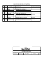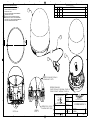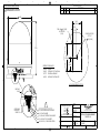
1
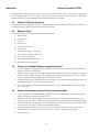
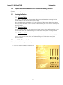
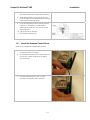
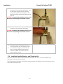
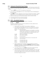
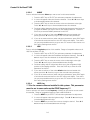
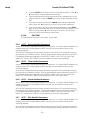
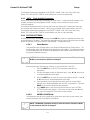
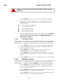
INSTALLATION AND MAINTENANCE MANUAL
FOR SEA TEL MODEL
COASTAL 14 SATELLITE TV RECEIVE-ONLY ANTENNA
Sea Tel, Inc.
4030 Nelson Avenue
Concord, CA 94520
Tel: (925) 798-7979
Fax: (925) 798-7986
Email: [email protected]
Web: www.seatel.com
September 26, 2007
Look to the Leader. Look to Sea Tel.
Sea Tel Europe
Unit 1, Orion Industrial Centre
Wide Lane, Swaythling
Southampton, UK S0 18 2HJ
Tel: 44 (0)23 80 671155
Fax: 44 (0)23 80 671166
Email: [email protected]
Web: www.seatel.com
Document. No. 126352
Revision B
Sea Tel Marine Stabilized Antenna systems are manufactured in the United
States of America.
Sea Tel is an ISO 9001:2000 registered company. Certificate Number 19.2867 was
issued August 12, 2005. Sea Tel was originally registered on November 09, 1998.
Copyright Notice
All Rights Reserved. The information contained in this document is proprietary to Sea Tel, Inc.. This
document may not be reproduced or distributed in any form without the consent of Sea Tel, Inc. The
information in this document is subject to change without notice.
Copyright © 2007 Sea Tel, Inc.
Revision History
REV
ECO#
Date
Description
By
A
N/A
February 17, 2006
Initial production release.
MDN
B
N/A
September 25, 2007
Modified text and drawings as needed
ECM
ii
Table of Contents
1. INSTALLATION .................................................................................................................................. 1-1
1.1.
SITE SELECTION AND CABLE ROUTING PATH .................................................................................... 1-1
1.2.
COASTAL 14 SYSTEM INVENTORY ................................................................................................... 1-2
1.3.
REQUIRED TOOLS ......................................................................................................................... 1-2
1.4.
PREPARE THE ANTENNA RADOME MOUNTING LOCATION ................................................................... 1-2
1.5.
PREPARE THE ANTENNA CONTROL PANEL MOUNTING LOCATION ....................................................... 1-2
1.6.
PREPARE THE SATELLITE RECEIVER AND TELEVISION MOUNTING LOCATIONS ....................................... 1-3
1.7.
RUNNING THE CABLES ................................................................................................................... 1-3
1.7.1.
Antenna Cable.................................................................................................................. 1-3
1.7.2.
Receiver Cable ................................................................................................................. 1-3
1.7.3.
DC Power Cable............................................................................................................... 1-3
1.8.
INSTALL THE ANTENNA RADOME .................................................................................................... 1-3
1.9.
INSTALL THE ANTENNA CONTROL PANEL ......................................................................................... 1-5
1.10. INSTALL THE SATELLITE RECEIVER AND TELEVISION SET .................................................................... 1-6
2. SETUP ................................................................................................................................................. 2-1
2.1.
SYSTEM CHECKOUT ...................................................................................................................... 2-1
2.2.
INITIAL FACTORY SETUP ................................................................................................................. 2-1
2.3.
CHANGING THE INITIAL FACTORY SETUP .......................................................................................... 2-1
2.4.
2.3.1.
Adjusting Panel Brightness .............................................................................................. 2-1
2.3.2.
Setting Auto Threshold for Proper Tracking..................................................................... 2-2
2.3.3.
SAT1 - First Satellite Parameters ................................................................................... 2-2
2.3.4.
SAT2 - Second Satellite Parameters .............................................................................. 2-6
2.3.5.
SAT3 - Third Satellite Parameters .................................................................................. 2-6
2.3.6.
SAT4 - Fourth Satellite Parameters................................................................................ 2-6
2.3.7.
SAT5 - Fifth Satellite Parameters ................................................................................... 2-6
2.3.8.
SAT6 - Sixth Satellite Parameters .................................................................................. 2-7
2.3.9.
FACTORY SETTINGS ....................................................................................................... 2-7
SAVING THE SETUP PARAMETERS ................................................................................................. 2-9
3. MAINTENANCE.................................................................................................................................. 3-1
3.1.
WARRANTY INFORMATION ............................................................................................................. 3-1
3.2.
WHO TO CONTACT FOR REPAIRS ..................................................................................................... 3-1
3.3.
PREVENTIVE MAINTENANCE ........................................................................................................... 3-2
3.4.
FAULT ISOLATION/TROUBLE-SHOOTING ........................................................................................... 3-2
3.5.
REPLACING A DEFECTIVE LNB........................................................................................................ 3-3
4. COASTAL 14 TECHNICAL SPECIFICATIONS................................................................................... 4-1
4.1.
INSTALLED WEIGHT ....................................................................................................................... 4-1
4.2.
RADOME ...................................................................................................................................... 4-1
4.3.
ANTENNA ..................................................................................................................................... 4-1
4.4.
STABILIZED PEDESTAL ................................................................................................................... 4-1
4.5.
US CIRCULAR LNB ....................................................................................................................... 4-2
4.6.
PEDESTAL CONTROL UNIT ............................................................................................................. 4-2
4.7.
POWER REQUIREMENTS ................................................................................................................ 4-2
iii
Table of Contents
4.8.
ENVIRONMENTAL .......................................................................................................................... 4-3
5. COMPUTER INTERFACE ...................................................................................................................5-4
5.1.
CONNECTING THE COMPUTER ......................................................................................................... 5-4
6. DRAWINGS.........................................................................................................................................6-7
6.1.
COASTAL 14 DRAWINGS ................................................................................................................ 6-7
iv
Coastal 14 Ku-Band TVRO
1.
Installation
Installation
Installation of your Coastal Series Antenna system must be accomplished by or under the supervision of
an authorized Sea Tel dealer for the Sea Tel Limited Warranty to be valid and in force. Good planning of
the installation will provide the best results. Below is some guidance on issues that are important to consider
when planning the installation.
Planning is the key to a good installation. Read the installation information below thoroughly before beginning
the actual installation. Then review your plan to adjust for any details that may have been overlooked.
A full scale Installation Template (drawing 126355) has been provided to locate the cutout areas and mounting
holes for the antenna radome and for the antenna control panel. The radome template section of the drawing
includes the outer perimeter of the radome base so you can insure that the radome will fit in the area chosen.
1.1.
Site Selection and Cable Routing Path
The best mounting location for the antenna radome assembly is where:
1. The antenna has a clear line-of-sight view to as much of the sky as is practical. Choose a location
where masts or other structures do not block the satellite signal from the dish as the boat turns.
2. The antenna is at least 5 feet away from other transmitting antennas (HF, VHF and radar) that
may generate signals that may interfere with the Coastal Series antenna. The further away the
Coastal antenna is from these
other antennas, the less impact
their operation will have on it.
3. The antenna radome assembly
should be rigidly mounted to
the boat. If necessary,
reinforce the mounting area to
assure that it does not flex due
to the boat motion or vibration.
Choosing the best mounting location on
smaller boats, where there are fewer
possible locations to choose from, is
frequently a compromise. The Figure
shown to the right is provided to make
some location comparisons. The
“poor” location is poor because over
half of the antenna’s viewable sky is
blocked by the overhang above it. The
“better” location has less blockage, but
Possible Antenna Radome Assembly mounting locations
the upper deck and the mast will cause
some blockage when the antenna is at
lower elevations. The “best” location has no blockage from raised platforms, mast or the body of the
radar.
The Antenna Control Panel (ACP) should be mounted in a convenient location close to the satellite
receiver and not more than 50 feet (total antenna cable path length) from the antenna radome. So that
the TV screen can be viewed while the antenna is being operated, it also should be mounted near the
satellite receiver and television.
1-1
Installation
Coastal 14 Ku-Band TVRO
The ACP and the satellite receiver should be mounted near each other which is connected to each other
with a supplied 6 foot RF receiver cable, If enclosed in a cabinet or panel, assure that there is adequate
airflow to prevent from over-heating and provide forced airflow if needed.
1.2.
Coastal 14 System Inventory
Please inventory the contents of the box. It should contain all items listed in the Coastal 14 Packing List
Document number 126370 found in the back of this manual.
1.3.
Required Tools
The following tools will be required to install the Coastal 14:
1. Masking tape
2. Center punch
3. Hammer
4. Electric Drill
5. 5/16” (8mm) Drill Bit
6. 1” hole saw
7. Small hand or electric saber saw
8. 7/16” Socket Wrench or Nut Driver
9. 7/16” Open-end Wrench
10. 1/8” straight blade screwdriver
11. #2 Phillips Head screwdriver
1.4.
Prepare the Antenna Radome mounting location
1. Lay the Installation Template (drawing 126355) on the mounting surface location that you have
chosen to mount the radome on.
2. Align the radome “bow” mark on the template to be parallel to the bow of the boat. Adjust the
position of the template to center the radome portion of the drawing where you want it. When
you are satisfied with the position tape the template in place.
3. Using the center punch and hammer, mark the locations of the four radome mounting holes and
the cable passage. Remove the template drawing.
4. Drill the four radome mounting holes using the 5/16” drill bit and the cable passage hole using
the 1” hole saw.
1.5.
Prepare the Antenna Control Panel mounting location
1. Lay the Installation Template (drawing 126355) on the mounting surface location that you have
chosen to mount the Antenna Control Panel in.
2. Adjust the position of the template to center the Antenna Control Panel cutout portion of the
drawing where you want it. When you are satisfied with the position tape the template in place.
3. Using the center punch and hammer, mark the locations of the four mounting holes and the four
corners of the cutout area. Remove the template drawing.
4. Mark the perimeter of the cutout area. Drill a hole inside the perimeter of the cutout area to
enable you to cut the area out with the saw (the 1” hole saw might be used for this).
5. Cut the area out.
1-2
Coastal 14 Ku-Band TVRO
1.6.
Installation
Prepare the Satellite Receiver and Television mounting locations
Prepare the mounting locations for the satellite receiver and television set ( or monitor and stereo sound
system).
1.7.
Running the Cables
1.7.1. Antenna Cable
Route the “F” connector end of the antenna cable down from the radome mounting location
through the boat to the antenna control panel location.
Adjust the cable routing so that about 12 inches (30.5cm) of cable extends beyond the radome
mounting surface and about 4 inches (10cm) of cable extending out of the antenna control panel
mounting surface.
1.7.2. Receiver Cable
Route the receiver cable from the antenna control panel location to the satellite receiver. Leave
about 4 inches (10cm) of cable extending out of the antenna control panel mounting surface.
1.7.3. DC Power Cable
Route the DC Power Cable from the antenna control panel location to the +12-24 Volt DC Power
source. Leave about 4 inches (10cm) of cable extending out of the antenna control panel
mounting surface.
1.8.
Install the Antenna Radome
Refer to the Installation Arrangement drawing.
1. Open the Radome Installation Hardware Kit.
1-3
Installation
Coastal 14 Ku-Band TVRO
2. Remove the radome top by removing the
three screws that thread into the radome
base.
3. Set the radome top aside in a safe location
until you are ready to close the radome.
4. Cut the shipping tie-wraps to allow free
movement of the antenna mechanism.
5. Thread a ¼-20 bolt through a bonded washer
(neoprene side down) and through one of the
threaded inserts in the base of the radome.
Install the other three bolts & bonded
washers in the same way.
6. Tighten all four of the mounting bolts
1-4
Coastal 14 Ku-Band TVRO
Installation
7. Lift the base of the radome up and connect
the antenna cable to the base of the antenna.
8. While being careful not to pinch or kink the
antenna cable, set the radome base mounting
bolts into the mounting holes.
9. From the underside of the mounting surface,
install a ¼” flat washer, a small pattern
washer and a nylon lock nut on each of the
mounting bolts.
10. Tighten all four of the nuts.
11. Re-install the radome top.
1.9.
Install the Antenna Control Panel
Refer to the Installation Arrangement drawing.
1. Assure that the DC Power Cable is not
connected to the DC Supply.
2. At the antenna control panel, connect the red
wire to the + (plus) terminal on the green
screw terminal.
3. Connect the black wire to the - (minus)
terminal on the green screw terminal.
1-5
Installation
Coastal 14 Ku-Band TVRO
4. Connect the antenna cable to the IN
connector of the antenna control panel. This
IN connection supplies 30VDC operating
voltage and antenna control signals to the
antenna and receives satellite signal from the
antenna.
CAUTION: Connecting the satellite receiver to the
IN connector may damage the satellite receiver.
5. Connect the receiver cable to the OUT
connector of the antenna control panel.
CAUTION: Connecting the satellite receiver to the
IN connector may damage the satellite receiver.
6. Install the antenna control panel into the
cutout and secure with self tapping screws
7. At the DC Power Supply, connect the red
wire to the plus voltage output terminal.
Connect the black wire to the minus (or
ground) output terminal.
1.10. Install the Satellite Receiver and Television Set
Connect the receiver cable from the antenna control panel’s RF “Out” Port to the satellite input
connection on the rear of your receiver.
Connect desired configuration of audio/video cables between the satellite receiver and television set (or
monitor & stereo equipment).
1-6
Coastal 14 Ku-Band TVRO
2.
Setup
Setup
2.1.
System Checkout
1. Press the ON key on the antenna control panel. Both LED’s (TRACKING and UNWRAP) should
illuminate for 5 seconds verifying the DC power and LED cable connections between the
antenna control panel and the antenna pedestal assembly.
2. Turn power ON to the satellite receiver and the TV monitor. The television may now be
displaying “searching for satellite signal” verifying proper video connections between the
receiver and the monitor.
2.2.
Initial Factory Setup
Your system comes from the factory preprogrammed for the following satellites:
SAT1
DTV 101 W
DirecTV 101 W
SAT2
DTV 110.1 W
DirecTV 110 W with 110 HD converter ON
SAT3
DTV 119 W
DirecTV 119 W
SAT4
Dsh 110 W
Dish Network 110 W
SAT5
Dsh 119 W
Dish Network 119 W
SAT6
Dsh 148 W
Dish Network 148 W
If you want to change this programming refer to the paragraphs below.
2.3.
Changing the Initial Factory Setup
If you want to change the order of the initial setup of satellites, remove unused satellites or add/replace
with new satellites then refer to the paragraphs below.
Press and hold SAVE + ▼ for 6 seconds to access SETUP Mode. “Setup Mode” will be displayed on
the first line of the display while the panel is in SETUP Mode.
Use the ▼ & ▲ arrow keys to scroll down & up through the Setup parameters listed below.
NOTE: You will save individual set-up parameter settings as you modify them in the
procedure below (quick presses of the SAVE key). These will only save the settings until
POWER is cycled to the antenna.
When you are finished making all of your desired changes, you MUST press and hold the
SAVE key for six seconds, “Settings Saved” will be displayed. Saving writes all of the
parameters, including the ones you have changed, to memory in the PCU so they will be
available after POWER has been cycled to the antenna.
2.3.1. Adjusting Panel Brightness
1. Press the NEXT key to SELECT this parameter for adjustment.
2. Once selected, press ▲& ▼ arrow keys to adjust the backlighting illumination of the
display to desired level. Each keypress steps the value 8 counts.
3. Then press the SAVE key to save the adjusted setting.
4. Press the ▼ arrow key to go to the next parameter.
2-1
Setup
Coastal 14 Ku-Band TVRO
2.3.2.
Setting Auto Threshold for Proper Tracking
Auto Threshold needs to be set to about 1/3rd of the difference in AGC between noise floor (OFF
satellite) signal level and peak (ON satellite) signal level. The most common value for the Coastal
14 is 60.
1. Press the NEXT key to SELECT this parameter for adjustment.
2. Once selected, press ▼ & ▲ arrow keys to increment/decrement the indicated digit to
the desired value.
3. Press NEXT to move the adjustment cursor to the next character to be edited. Press ▼
& ▲ arrow keys to increment/decrement the indicated character to the desired value.
4. Repeat the previous step until all desired character positions have been edited.
5. Then press the SAVE key once to save this setting.
6. Press the ▼ arrow key to go to the next parameter.
2.3.3.
SAT1 - First Satellite Parameters
Access all of the SAT1 individual parameters via a sub menu. Choices are:
2.3.3.1.
PRESET
This choice presets all of the other sub-menu parameters to factory defaults for the
satellite you choose to set this SAT to.
1. Press the NEXT key to SELECT this parameter for adjustment.
2. Once selected, press ▼ & ▲ arrow keys to scroll through a list of choices
which this SAT can be preset to. This list may change in future software
revisions. The current choices are:
Empty
Blanks/zeroes all parameters for this satellite, so switching
satellites (NEXT) will skip over the satellites you don’t want
(if you only use ONE satellite, you should preset all of the
other SAT selections to be empty/blank).
ExpV82
Bell ExpressVu @ 82W
ExpV91
Bell ExpressVu @ 91W
DTV101
DirecTV @ 101W
DTV110.1
DirecTV @ 110.1W (this turns the 110 converter ON)
DTV119
DirecTV @ 119W
Dsh110
Dish Network @ 110W
Dsh119
Dish Network @ 119W
Dsh148
Dish Network @ 148W
3. When the desired choice is displayed, press the SAVE key to save the
parameters for this SAT. This saves the DEFAULT Satellite Name, Satellite
Longitude, LHCP frequency, RHCP frequency, Baud rate, FEC rate, Network
ID and Polarization Trim of this SAT.
4. If you want to edit any of the default values that are loaded with preset,
press the ▼ arrow key to go to the next sub-menu parameter.
5. If you do not want to edit any other sub-menu parameters, press SAVE again
to exit the sub-menu and return to the SAT main menu display. From there
you can press the ▼ arrow key to go to next SAT numeric menu choice or to
the Factory Settings menu choice.
2-2
Coastal 14 Ku-Band TVRO
2.3.3.2.
Setup
NAME
Enter or edit the 6 character Name you want to use for this saved satellite.
1. Press the NEXT key to SELECT this sub-menu parameter for adjustment.
2. A cursor will appear under the leftmost character. Press ▼ & ▲ arrow keys
to increment/decrement this character.
3. Press the NEXT key to move the cursor to the next character to the right.
Press ▼ & ▲ arrow keys to increment/decrement this character.
4. Continue editing characters (6 max) until all desired characters have been set
to create the NAME you want to use for this satellite selection. Press the
SAVE key to save the NAME parameter for this SAT.
5. If you want to edit any of the other default values that are loaded with
preset, press the ▼ arrow key to go to the next sub-menu parameter.
6. If you do not want to edit any other sub-menu parameters, press SAVE again
to exit the sub-menu and return to the SAT main menu display. From there
you can press the ▼ arrow key to go to next SAT numeric menu choice or to
the Factory Settings menu choice.
2.3.3.3.
LON
Enter or edit the Longitude position of this satellite. Range of acceptable values are 0180, East or West (E or W).
1. Press the NEXT key to SELECT this sub-menu parameter for adjustment.
2. A cursor will appear under the East/West hemisphere character. Press ▼ &
▲arrow keys to set this character to the desired hemisphere (E/W).
3. Press the NEXT key to move the cursor to the number digit to the right.
Press ▼ & ▲ arrow keys to increment/decrement this digit.
4. Continue editing until all 3 digits have been set to the Longitude (0-180)
position of this satellite selection. Press the SAVE key to save the LON
parameter for this SAT.
5. If you want to edit any of the other default values that are loaded with
preset, press the ▼ arrow key to go to the next sub-menu parameter.
6. If you do not want to edit any other sub-menu parameters, press SAVE again
to exit the sub-menu and return to the SAT main menu display. From there
you can press the ▼ arrow key to go to next SAT numeric menu choice or to
the Factory Settings menu choice.
2.3.3.4.
LHCP freq
***For the current software installed in this system. This parameter
must be set to same value as the RCHP frequency***
Enter or edit the Left Hand Circular Frequency (in MHz) for the receiver to use to track
this satellite. Range of acceptable frequency input is 950-2150 MHz.
1. Press the NEXT key to SELECT this sub-menu parameter for adjustment.
2. A cursor will appear under the rightmost digit. Press ▼ & ▲ arrow keys to
increment/decrement this digit.
3. Press the NEXT key to move the cursor to the digit to the left. Press ▼ &
▲ arrow keys to increment/decrement this digit.
2-3
Setup
Coastal 14 Ku-Band TVRO
4. Continue editing until all 4 digits have been set to the desired tracking
Frequency for this satellite selection. Press the SAVE key to save the FREQ
parameter for this SAT.
5. If you want to edit any of the other default values that are loaded with
preset, press the ▼ arrow key to go to the next sub-menu parameter.
6. If you do not want to edit any other sub-menu parameters, press SAVE again
to exit the sub-menu and return to the SAT main menu display. From there
you can press the ▼ arrow key to go to next SAT numeric menu choice or to
the Factory Settings menu choice.
2.3.3.5.
RHCP freq
Enter or edit the best Right Hand Circular Frequency (in MHz) for the receiver to use to
track this satellite. Range of acceptable frequency input is 950-2150 MHz.
1. Press the NEXT key to SELECT this sub-menu parameter for adjustment.
2. A cursor will appear under the rightmost digit. Press ▼ & ▲ arrow keys to
increment/decrement this digit.
3. Press the NEXT key to move the cursor to the digit to the left. Press ▼ & ▲
arrow keys to increment/decrement this digit.
4. Continue editing until all 4 digits have been set to the desired tracking
Frequency for this satellite selection. Press the SAVE key to save the FREQ
parameter for this SAT.
5. If you want to edit any of the other default values that are loaded with
preset, press the ▼ arrow key to go to the next sub-menu parameter.
6. If you do not want to edit any other sub-menu parameters, press SAVE again
to exit the sub-menu and return to the SAT main menu display. From there
you can press the ▼arrow key to go to next SAT numeric menu choice or to
the Factory Settings menu choice.
2.3.3.6.
BAUD
Enter or edit the best Baud rate for the receiver to use for this satellite. Range of
acceptable input is 5000-30000 symbols per second.
1. Press the NEXT key to SELECT this sub-menu parameter for adjustment.
2. A cursor will appear under the rightmost digit. Press ▼ & ▲ arrow keys to
increment/decrement this digit.
3. Press the NEXT key to move the cursor to the digit to the left. Press ▼ & ▲
arrow keys to increment/decrement this digit.
4. Continue editing until all 5 digits have been set to the desired Baud rate for
this satellite selection. Press the SAVE key to save the BAUD parameter for
this SAT.
5. If you want to edit any of the other default values that are loaded with
preset, press the ▼ arrow key to go to the next sub-menu parameter.
6. If you do not want to edit any other sub-menu parameters, press SAVE again
to exit the sub-menu and return to the SAT main menu display. From there
you can press the ▼ arrow key to go to next SAT numeric menu choice or to
the Factory Settings menu choice.
2-4
Coastal 14 Ku-Band TVRO
Setup
2.3.3.7.
FEC
Enter or edit the best Forward Error Correction rate for the receiver to use for this
satellite.
This choice presets all of the other sub-menu parameters to factory defaults for the
satellite you choose to set this SAT to.
1. Press the NEXT key to SELECT this parameter for adjustment.
2. Once selected, press ▼ & ▲ arrow keys to scroll through a list of choices
which this SAT can be preset to. This list may change in future software
revisions. The current choices are:
AUTO
Automatically scans through all the standard DVB & DSS
FEC rates.
1/2
2/3
3/4
5/6
6/7
7/8
AUTO*
Automatically scans through all the available forced *
(star’ed) FEC rates. If the satellite does not generate an NID
but does have a unique combination of FREQ, BAUD and
FEC lock, select the appropriate FEC* choice from this list.
The system will then generate its own unique forced NID to
represent the desired satellite. You will need to enter this
pseudo NID in the NID setting below.
1/2*
2/3*
3/4*
5/6*
6/7*
7/8*
3. When the desired choice is displayed, press the SAVE key to save the
parameters for this SAT. This saves the FEC rate to use for this SAT.
4. If you want to edit any of the default values that are loaded with preset,
press the ▼arrow key to go to the next sub-menu parameter.
5. If you do not want to edit any other sub-menu parameters, press SAVE again
to exit the sub-menu and return to the SAT main menu display. From there
you can press the ▼ arrow key to go to next SAT numeric menu choice or to
the Factory Settings menu choice.
2.3.3.8.
NID
Enter or edit the best Network ID 4 digit HEX value for the receiver used to Identify &
track this satellite.
1. Press the NEXT key to SELECT this sub-menu parameter for adjustment.
2. A cursor will appear under the rightmost digit. Press ▼ & ▲ arrow keys to
increment/decrement this digit (only valid HEX values 0-F will be displayed).
2-5
Setup
Coastal 14 Ku-Band TVRO
3. Press the NEXT key to move the cursor to the digit to the left. Press ▼ &
▲ arrow keys to increment/decrement this digit.
4. Continue editing until all 4 digits have been set to the desired NID for this
satellite selection. Press the SAVE key to save the NID parameter for this
SAT.
5. If you want to edit any of the other default values that are loaded with
preset, press the ▼arrow key to go to the next sub-menu parameter.
6. If you do not want to edit any other sub-menu parameters, press SAVE
again to exit the sub-menu and return to the SAT main menu display. From
there you can press the ▼ arrow key to go to next SAT numeric menu
choice or to the Factory Settings menu choice.
2.3.3.9.
POL TRIM
This parameter is not used in this system. Set to 0000.
2.3.4.
SAT2 - Second Satellite Parameters
Access all of the SAT2 individual parameters via a sub menu. If a second SAVED satellite if not
needed, preset SAT2 to empty/blank so NEXT will skip over this selection when you are
switching satellites.
All of the SAT2 parameters are set exactly the same way that the SAT1 parameters were set,
but would be set to different choices. Refer to the parameter setting information in the SAT1 –
First Satellite Parameters paragraphs to set PRESET, NAME, LON, LHCP freq, RHCP freq,
BAUD, FEC, NID and POL TRIM for a second satellite you wish to use periodically.
2.3.5.
SAT3 - Third Satellite Parameters
Access all of the SAT3 individual parameters via a sub menu. If a second SAVED satellite if not
needed, preset SAT3 to empty/blank so NEXT will skip over this selection when you are
switching satellites.
All of the SAT3 parameters are set exactly the same way that the SAT1 parameters were set,
but would be set to different choices. Refer to the parameter setting information in the SAT1 –
First Satellite Parameters paragraphs to set PRESET, NAME, LON, LHCP freq, RHCP freq,
BAUD, FEC, NID and POL TRIM for a third satellite you wish to use periodically.
2.3.6.
SAT4 - Fourth Satellite Parameters
Access all of the SAT4 individual parameters via a sub menu. If a second SAVED satellite if not
needed, preset SAT4 to empty/blank so NEXT will skip over this selection when you are
switching satellites.
All of the SAT4 parameters are set exactly the same way that the SAT1 parameters were set,
but would be set to different choices. Refer to the parameter setting information in the SAT1 –
First Satellite Parameters paragraphs to set PRESET, NAME, LON, LHCP freq, RHCP freq,
BAUD, FEC, NID and POL TRIM for a fourth satellite you wish to use periodically.
2.3.7.
SAT5 - Fifth Satellite Parameters
Access all of the SAT5 individual parameters via a sub menu. If a second SAVED satellite if not
needed, preset SAT5 to empty/blank so NEXT will skip over this selection when you are
switching satellites.
All of the SAT5 parameters are set exactly the same way that the SAT1 parameters were set,
but would be set to different choices. Refer to the parameter setting information in the SAT1 –
2-6
Coastal 14 Ku-Band TVRO
Setup
First Satellite Parameters paragraphs to set PRESET, NAME, LON, LHCP freq, RHCP freq,
BAUD, FEC, NID and POL TRIM for a fifth satellite you wish to use periodically.
2.3.8.
SAT6 - Sixth Satellite Parameters
Access all of the SAT6 individual parameters via a sub menu. If a second SAVED satellite if not
needed, preset SAT6 to empty/blank so NEXT will skip over this selection when you are
switching satellites.
All of the SAT6 parameters are set exactly the same way that the SAT1 parameters were set,
but would be set to different choices. Refer to the parameter setting information in the SAT1 –
First Satellite Parameters paragraphs to set PRESET, NAME, LON, LHCP freq, RHCP freq,
BAUD, FEC, NID and POL TRIM for a sixth satellite you wish to use periodically.
2.3.9. FACTORY SETTINGS
Accessing the Factory Settings parameters should ONLY be done by a qualified technician from
an authorized Sea Tel dealer. The Model Serial Number can be found on the blue and silver label
below the reflector, on the blue frame of the pedestal. The parameters are:
2.3.9.1.
Serial Number
This parameter sets Serial Number of the Antenna Pedestal into the PCU memory. The
serial number starts with 98 followed by 6 digits that are editable. This parameter allows
the Serial Number of the Antenna to be displayed on the Display Antenna Control Panel
during the initialization process.
NOTE: The Serial Number parameter setting is saved in the PCU, therefore,
MUST be set whenever the PCU is changed.
After this parameter has been set correctly, it must be SAVED in the PCU.
1. Press the NEXT key to SELECT this sub-menu parameter for
adjustment.
2. A cursor will appear under the rightmost digit. Press ▼ & ▲ arrow keys
to increment/decrement this digit.
3. Press the NEXT key to move the cursor to the digit to the left. Press ▼
& ▲ arrow keys to increment/decrement this digit.
4. Continue editing until all 6 digits have been set to the correct Serial
Number of the antenna pedestal that this PCU is mounted on. Press the
SAVE key to save the Serial Number parameter.
5. Press SAVE again to exit the sub-menu and return to the FACTORY
SETTINGS main menu display. From there you can press the ▲ arrow
key to go UP through the SAT numeric menu choices.
2.3.9.2.
MODEL COASTAL ##
This parameter sets all of the internal drive, scale factor and limits for the motors, gear
ratios and sensors FOR THIS MODEL ANTENNA.
NOTE: The MODEL parameter setting is saved in the PCU, therefore, MUST
be set whenever the PCU is changed.
2-7
Setup
Coastal 14 Ku-Band TVRO
WARNING: Improper setting of this parameter WILL cause the antenna to
malfunction.
1. Press the NEXT key to SELECT this sub-menu parameter for adjustment.
2. Once selected, press ▼ & ▲arrow keys to scroll through a list of model
number choices. This list may change in future software revisions. The
current choices are:
14
14 inch diameter reflector
18
18 inch diameter reflector
20
20 inch diameter reflector
24
24 inch diameter reflector
30
30 inch diameter reflector
3. When the correct model value (Coastal 14) is displayed, press the SAVE key
to save the Model Number parameters. This saves the drive, scale factors
and limits for this antenna. If this parameter is NOT set correctly, the
antenna WILL malfunction.
2.3.9.3.
LAT (Ships Latitude)
This parameter is automatically set by the GPS antenna mounted on the Coastal pedestal
inside the radome. The GPS input enables the antenna to quickly & accurately target
satellites (SAT1 – SAT6) when you press the NEXT key on the Antenna Control Panel.
1. Press the NEXT key to SELECT this sub-menu parameter for adjustment.
2. A cursor will appear under the leftmost digit. Press ▼ & ▲ arrow keys to
increment/decrement this digit.
3. Press the NEXT key to move the cursor to the next digit to the right.
Press▼ & ▲arrow keys to increment/decrement this digit.
4. Press the NEXT key to move the cursor to the next character to the right.
Press ▼ & ▲ arrow keys to toggle this character between N (North) and S
(South).
5. Press the SAVE key to save the current ships latitude in the LAT parameter.
2.3.9.4.
LON (Ships Longitude)
This parameter is automatically set by the GPS antenna mounted on the Coastal pedestal
inside the radome. The GPS input enables the antenna to quickly & accurately target
satellites (SAT1 – SAT6) when you press the NEXT key on the Antenna Control Panel.
1. Press the NEXT key to SELECT this sub-menu parameter for adjustment.
2. A cursor will appear under the leftmost digit. Press ▼ & ▲ arrow keys to
increment/decrement this digit.
3. Press the NEXT key to move the cursor to the next digit to the right. Press
▼ & ▲ arrow keys to increment/decrement this digit.
4. Press the NEXT key to move the cursor to the next digit to the right. Press
▼ & ▲ arrow keys to increment/decrement this digit.
2-8
Coastal 14 Ku-Band TVRO
Setup
5. Press the NEXT key to move the cursor to the next character to the right.
Press ▼ & ▲ arrow keys to toggle this character between E (East) and W
(West).
6. Press the SAVE key to save the current ships longitude in the LON
parameter.
2.4.
Saving the SETUP Parameters
When you have completed setting the desired parameters above, Press and Hold SAVE for 6 seconds to
save the changes you have made to the settings and exit SETUP Mode. “Settings Saved” will be
displayed.
If you do NOT want to save the changes to NVRAM, Press SAVE +▲ to exit SETUP Mode without
permanently saving any parameter changes.
NOTE: You will save individual set-up parameter settings as you modify them in the
procedure below (quick presses of the SAVE key). These will only save the settings until
POWER is cycled to the antenna.
When you are finished making all of your desired changes, you MUST press and hold the
SAVE key for six seconds to write the changes you have made to memory (“Settings
Saved” will be displayed) in the PCU, so they will be available after POWER has been
cycled to the antenna.
2-9
Setup
Coastal 14 Ku-Band TVRO
This Page Intentionally Left Blank
2-10
Coastal 14 Ku-Band TVRO
3.
Maintenance
Maintenance
3.1.
Warranty Information
Sea Tel Inc. supports its Coastal Series systems with a warranty program unsurpassed in the industry.
These systems are backed by a TWO YEAR full warranty on parts and a ONE YEAR warranty on labor.
What’s Covered by the Limited Warranty?
The Sea Tel Coastal Series Limited Warranty is applicable for parts and labor coverage to the complete
antenna system, including all above-decks equipment (radome, pedestal, antenna, motors, electronics,
wiring, etc.) and the antenna control panel. It does not include television sets, DBS/DTH receivers, multiswitches or other distribution equipment, whether or not supplied by Sea Tel. Televisions, DBS/DTH
receivers and accessories are covered by the applicable warranties of the respective manufacturers.
Factory refurbished components used to replace systems parts under this warranty are covered by this
same warranty as the original equipment for the balance of the original warranty term, or ninety (90) days
from the date of replacement, whichever occurs last. Original Installation of the Coastal Series system
must be accomplished by or under the supervision of an authorized Sea Tel dealer for the Sea Tel Limited
Warranty to be valid and in force.
Please refer to the complete warranty information included with your system.
3.2.
Who to contact for repairs
Should technical assistance be required to repair your system, the first contact should be to the
agent/dealer you purchased the equipment from. Please record their contact information below for
future reference. Repairs to your Coastal Series system must be accomplished by or under the
supervision of an authorized Sea Tel dealer for the Sea Tel Limited Warranty to be valid and in force.
Agent/Dealer: _________________________________________
Address:
_________________________________________
_________________________________________
Phone: ______________________ Fax: ____________________
Sea Tel can recommend local dealers that can provide service in your local area that can be contacted for
assistance. You can contact us directly at either of the locations below;
Sea Tel, Inc.
Sea Tel Europe
4030 Nelson Avenue
Unit 1 Orion Industrial Centre
Concord, CA 94520 USA
Wide Lane Swaythling
Tel:
925-798-7979
Southampton, UK S018 2HJ
Fax:
925-798-7986
Tel: +44 (0)23 80 671155
Toll Free: 1-888-798-7979
Fax: +44 (0)23 80 671166
Email: [email protected]
e-mail: [email protected]
http://www.seatel.com
3-1
Maintenance
3.3.
Coastal 14 Ku-Band TVRO
Preventive Maintenance
As needed - Clean the outside surface of the radome with warm soapy water to remove dust, grime and
salt residue.
There is no other preventive maintenance required
3.4.
Fault Isolation/Trouble-shooting
The following table is provided to help isolate problems in the Coastal Series Antenna system.
Symptom
Antenna tracking but receiver not
providing desired programming
Possible Fault
1. Incorrect satellite. Press NEXT to search for desired
satellite
2. Receiver fault. Refer to receiver manual for operation
and testing.
Antenna tracking, receiver only gets
some desired channels
1. May be in weak area of footprint.
2. Receiver may not be generating correct voltage or
tone output. Refer to receiver manual for operation
and testing.
3. Receiver may not be passing voltage or tone output.
Contact your dealer/agent.
4. LNB assembly failure. Contact your dealer/agent.
Intermittent freeze-framing of
picture
1. Check for blockage
2. May be in weak area of footprint.
3. Receiver may not be generating correct voltage or
tone output. Refer to receiver manual for operation
and testing.
4. Check all coax cables for poor connection
5. Possible receiver failure. Contact your dealer/agent.
6. Possible antenna failure. Contact your dealer/agent.
Antenna does not come on when
the ON key is pressed
1. Check +12 VDC input to antenna control panel.
2. Verify that all connections on the rear of the antenna
control panel are properly seated.
3. Check the 4A fuse in the rear panel of the antenna
control panel
4. Call dealer/agent for further assistance
Antenna doesn’t track any satellites
1. Assure that the satellite receiver is turned ON
(constantly searching)
2. Check for blockage
3. Assure correct starting elevation
4. May be out of satellite footprint
5. Check all coax cables for poor connection
6. Call dealer/agent for further assistance
Antenna in constant UNWRAP
1. Cycle antenna power OFF/ON to reinitialize the
antenna.
2. Call dealer/agent for further assistance
3-2
Coastal 14 Ku-Band TVRO
Maintenance
Antenna tracks well at the pier, but
loses the satellite when underway
1. Call dealer/agent for further assistance
Antenna does not stay on satellite
at pier, or underway
1. Check all coax cables for poor connection
3.5.
2. Call dealer/agent for further assistance
Replacing a Defective LNB
Follow the procedure below to install a replacement LNB.
1. Turn antenna power OFF at the
antenna control panel.
2. Remove radome top.
3. You may need to rotate the antenna to
gain access the back of the dish.
4. Note that the body of the current
Circular LNB is vertical (straight down).
5. Loosen the screws on the existing
LNB mounting collar (two screws, 120
degrees apart) and extract the
defective LNB from the mounting
collar.
6. Insert the new LNB (same style) into
the mounting collar, assure it is seated
all the way into the mounting collar
tube, rotate the LNB as needed to
align the center of the body of the
circular LNB to a vertical position
(straight down) and tighten the
screws.
7. Transfer the coax cables from the old
LNB to the new LNB, assure that the
correct color coax is attached to the
correct port on the LNB.
8. Re-install the radome top and tighten
radome hardware.
9. Turn antenna power ON at the
antenna control panel.
10. Verify that the LNB operating properly
and resume normal operation.
3-3
Maintenance
Coastal 14 Ku-Band TVRO
This Page Intentionally Left Blank
3-4
Coastal 14 Ku-Band TVRO
4.
Coastal 14 Technical Specifications
Coastal 14 Technical Specifications
4.1.
Installed Weight
Total Weight (dry):
4.2.
25 lbs. (11.3 kg)
Radome
Diameter
16.5 inch (41.9cm)
Height
18 inch (45.7cm)
Mounting
4 x ¼-20 fasteners
Wind:
Withstand relative average winds up to 100 MPH from any
direction.
Ingress Protection Rating
All Sea Tel radomes have an IP rating of 56
4.3.
Antenna
Type
Spun Aluminum reflector
Size
14.5 inch (36.8cm)
Feed
Cassegrain feed with center focus splash plate
Polarization
Circular ONLY
Min EIRP
50 dB
LNB
US Circular LNB
4.4.
Stabilized Pedestal
Type
Two-axis positioning (Elevation & Azimuth) and Polarization
Stabilization
3 Dimensional Velocity mode Servo
Stab Accuracy
1.5 degrees MAX, 0.7 degrees RMS in presence of
specified ship motions.
Level, Train Motors
Size 23 DC Step Motors with PWM Microstep drive
Inertial Reference
3 single axis Solid State Silicon Rate Sensors
Gravity Reference
Two Axis Fluid Tilt Sensor
Azimuth Reference
Closed Loop Tracking on Satellite signal
Stabilization rates
Roll/Pitch
> 25 degrees / second
AZ./Turn
> 15 degrees / second
Range of Motion
Elevation
15 to 75 degrees
Azimuth
Unlimited
Polarization
+/- 90 degrees
Maximum Ship Motion
Roll
+/- 25 degrees
Pitch
+/- 15 degrees
4-1
Coastal 14 Technical Specifications
Coastal 14 Ku-Band TVRO
Elevation Pointing
4.5.
+/- 15 degrees of Roll
35 to 60 degrees
+/- 25 degrees of Roll
40 to 50 degrees
US Circular LNB
Sea Tel Part Number:
115075-1
Type:
Single output
LNB Manufacturer:
Wistron Neweb, but may vary
RF Frequencies:
12.2 - 12.7 GHz
IF Frequency:
950 - 1450 MHz
LO Frequency:
11.250 GHz
Noise Figure:
1.1 dB max.
Polarization modes:
LHCP or RHCP circular
Polarization control:
18VDC (LHCP) or 13VDC (RHCP) voltage switched in
pedestal
4.6.
Pedestal Control Unit
Size
6 x 8.5 x 2.125 inches (15.24 x 21.6 x 5.4 cm)
Features
Fully integrated controller, sensors, motor drivers, and RF
signal Tracking Receiver.
Connectors
Below Decks Interface
15 pin D-Sub
Elevation/Azimuth Drive Motors 9 pin D-Sub
Polarization Motor
9 pin D-Sub
Elevation Encoder
9 pin D-Sub
RF Signal Input
Type F
RF Signal Output
Type F
HD 110W Converter Enable
Type F
GPS Antenna Input
BNC
Error! Not a valid filename.
4.7.
Power Requirements
Voltage
12-24 VDC normal operating range
Current
3.0 Amps nominal @ 13.8 VDC
Transient Protection
Load Dump
60 volts
Inductive coupling
+/- 200v @ 1 uSec
Reverse Battery
Indefinite
24V Jump Start
1 minute
4-2
Coastal 14 Ku-Band TVRO
4.8.
Coastal 14 Technical Specifications
Environmental
Temperature
-20 to +55 degrees C.
Humidity
Up to l00% @ 40 degrees C.
Rain
Up to 4 inches per hour. Degraded RF performance when
the radome surface is wet.
Wind
Up to 100 MPH from any direction.
Corrosion
Parts are corrosion resistant or treated to endure effects of
salt air and salt spray.
Ship Motions for specified pointing accuracy
Roll
+/-20 degrees with 8-12 sec periods
Pitch
+/-10 degrees with 6-12 sec periods
Yaw
+/-8 degrees with 15 to 20 sec periods
Turning rate
Up to 12 deg/sec.
4-3
Computer Interface
5.
Coastal 14 Ku-Band TVRO
Computer Interface
A computer can be connected to the antenna control panel to allow you to provide access to ALL the parameter
settings of the query the Coastal Series antenna and view the responses it provides. The commands to set the
parameters in the Coastal Series PCU are summarized below.
Changing the parameters for the primary and secondary satellites may be easily done using the
computer interface. You may consult the Lyngsat satellite web site at www.lyngsat.com for detailed tuning
frequencies and network ID information (Note hold your cursor over the Ku band transponder frequency to show
the L-band IF tuning value in the lower left status bar display based on the most popular Local Oscillator
frequencies). If you LNB uses a different Local Oscillator frequency, you will have to calculate the IF to tune to
(RF – LO = IF).
5.1.
Connecting the computer
1
Connect the computers COM port to the Receiver
Interface port on the rear of the Display Antenna
Control Panel using a computer “DB-9 Serial
Extension Cable” (male-female) available in most
computer stores.
2
Use Hyper Terminal, or another communication
program, to communicate with the Series 98
system. If you have previously set up Hyper
Terminal skip to step 7 below.
3
COM port settings should be set to 9600 bits per
second, 8 data bits, No parity, 1 stop bit.
4
Assure that the Flow Control is set to “None”.
5
Open Hyper Terminal and select the settings tab.
6
Click on ASCII Setup to configure Hyper Terminal.
5-4
Coastal 14 Ku-Band TVRO
Computer Interface
7
Check “Send line ends with line feeds”, “Echo
typed characters locally” and “Append line feeds to
incoming line ends”. Click OK.
8
Type ^0086 and hit ENTER.
9
Refer to the command information below to
communicate with the antenna system. The Display
Antenna Control Panel will be locked while you are
connected to the computer.
10 When you are finished, close the terminal program
and disconnect the computer from the Display
Antenna Control Panel.
11 At the Display Antenna Control Panel, Turn power
OFF. Wait 10 seconds and turn power ON.
5-5
Computer Interface
Coastal 14 Ku-Band TVRO
This Page Intentionally Left Blank
5-6
Coastal 14 Ku-Band TVRO
6.
Drawings
The following drawings are included with this manual for installation and maintenance reference.
6.1.
Coastal 14 Drawings
Drawing
Title
125818_D
System, Coastal 14
125699-1_C
System Block Diagram
6-11
126340_A1
Antenna Schematic
6-13
125773_E
General Assembly
6-14
125817_A2
Antenna Assembly
6-17
125822_C
Radome Assembly
6-19
126357_A1
Installation Arrangement
6-21
126370_D
Packing List Coastal 14
6-22
126355_A1
6-9
Installation Template (provided separately)
6-7
Drawings
Coastal 14 Ku-Band TVRO
This page left blank intentionally
6-8
SINGLE LEVEL MFG BILL OF MATERIAL
FIND
QTY
PART NO
REV DESCRIPTION
REFERENCE DESIGNATOR
1
1
EA
125773
E
GENERAL ASS'Y, COASTAL 14
2
1
EA
125822
C
RADOME ASS'Y, COASTAL 14
3
1
EA
126059
A
ANTENNA CONTROL PANEL ASS'Y, TACP
4
1
EA
113480-1
C1
CABLE ASS'Y, RF, RG6, 50 FT.
5
1
EA
111115-6
B
CABLE ASS'Y, F(M)-F(M), 6 FT.
6
1
EA
126305
A
HARNESS ASS'Y, DC POWER, COASTAL 1 (NOT SHOWN)
8
1
EA
126372
A
CUSTOMER DOC PACKET, COASTAL 14
9
1
EA
110567-11
10
1
EA
126370
11
1
EA
126594-1
(NOT SHOWN)
ADAPTER, N(M)-F(F), STRAIGHT
(NOT SHOWN)
D
PACKING LIST, COASTAL 14
(NOT SHOWN)
B
GA INSTALL, COASTAL 14
(NOT SHOWN)
SYSTEM, COASTAL 14
PROD FAMILY
SERIES 98
EFF. DATE
25-Sep-07
SHT 1 OF 1
DRAWING NUMBER
125818
REV
D
8
6
7
5
4
NOTES: UNLESS OTHERWISE SPECIFIED
1. APPLY ADHESIVE PER SEATEL SPEC. 121730.
D
2. TORQUE THREADED FASTENERS PER
SEATEL SPEC. 122305.
3. ROUTE ALL HARNESS AND CABLES ASSEMBLIES
PER SEATEL SPEC. 121872.
4. APPLY 1 DALLOP OF ELECTRICAL INSULATION
COMPOUND, P/N: 126294 AT THE JOINT BETWEEN
CABLE ASS'Y, P/N: 125964-10 AND SMB CONNECTOR,
P/N:125763-1 BEFORE INSTALLING CABLE.
A
REV
2
2
3
1
REVISION HISTORY
DESCRIPTION
ECO# DATE
BY
B
5464
02/14/07
ADDED 126372 CUSTOMER DOCUMENT PACKET TO BOM.
KRB
C
5510
03/26/07
ITEM 4 WAS 126306-1.
KRB
D
5562
4-26-07
ADDED ITEMS 10 & 11; UPDATED VIEWS; ADDED REFERENCE DWGS.
RJW
D
4
A
C
C
1
3
B
B
4
REFERENCE CABLE ASS'Y 125964-10
IN GENERAL ASS'Y 125773.
REFERENCE DRAWINGS:
125699 SYSTEM BLOCK DIAGRAM, COASTAL 14
126340 SCHEMATIC, ANTENNA, COASTAL 14
UNLESS OTHERWISE SPECIFIED
DIMENSIONS ARE IN INCHES.
X.X = .050
X.XX = .020
X.XXX = .005
ANGLES: .5
A
DRAWN BY:
Sea
KRB
DRAWN DATE:
02/01/07
APPROVED BY:
REFERENCE P/N: 125763-1
IN RADOME ASS'Y 125822
B
DETAIL B
SCALE 1 : 2
SECTION A-A
7
6
N/A
FINISH:
N/A
5
4
SYSTEM, COASTAL 14
APPROVED DATE:
3rd ANGLE
PROJECTION
8
A
TITLE:
INTERPRET TOLERANCING PER ASME Y14.5M - 1994
MATERIAL:
Tel
4030 NELSON AVENUE
CONCORD, CA 94520
Tel. 925-798-7979 Fax. 925-798-7986
SIZE
SCALE:
B
1:5
125818
D
1 OF 1
SHEET NUMBER
FIRST USED:
3
REV
DRAWING NUMBER
2
1
SINGLE LEVEL MFG BILL OF MATERIAL
FIND
QTY
PART NO
REV DESCRIPTION
REFERENCE DESIGNATOR
1
1
EA
125773
E
GENERAL ASS'Y, COASTAL 14
2
1
EA
125822
C
RADOME ASS'Y, COASTAL 14
3
1
EA
125824
A1
FEED, 14" ANTENNA, COASTAL 14
4
1
EA
115075-1
G1
LNB MOD, DUAL, US
5
1
EA
123092
A
CONVERTER, HDTV 110 WEST
6
1
EA
121966-2
D
GPS ANTENNA, RETERMINATED, 21.0 L
7
1
EA
126068-1
A
PCU ENCLOSURE ASS'Y, 2-AXIS, COASTA
8
1
EA
126083
B
FSK ENCLOSURE ASS'Y, ADE, COASTAL 1
9
1
EA
125763-1
A
ADAPTER, SMB (M) TO N (F), 75 OHM, BUL
11
1
EA
126059
A
ANTENNA CONTROL PANEL ASS'Y, TACP
12
1
EA
117164-10BLK
A4
CABLE ASS'Y, RG-179 COAX, F TO F, 10 IN,
13
1
EA
117164-14BLK
CABLE ASS'Y, RG-179 COAX, F TO F, 14 IN,
14
2
EA
117164-12BLK
CABLE ASS'Y, RG-179 COAX, F TO F, 12 IN,
15
1
EA
126075-1
B
HARNESS ASS'Y, INTERFACE, COASTAL 1
16
1
EA
125964-10
B
CABLE ASS'Y, RG-179 COAX, F(M) TO SMB
17
1
EA
113480-1
C1
CABLE ASS'Y, RF, RG6, 50 FT.
18
1
EA
111115-6
B
CABLE ASS'Y, F(M)-F(M), 6 FT.
19
1
EA
126305
A
HARNESS ASS'Y, DC POWER, COASTAL 1
20
2
EA
110026-3
ADAPTER, F, 90 DEG
21
1
EA
110567-11
ADAPTER, N(M)-F(F), STRAIGHT
22
1
EA
125245-1
A
HARNESS ASS'Y, ENCODER, COASTAL SE
SYSTEM BLOCK DIAGRAM, COASTAL 14
PROD FAMILY
LIT
EFF. DATE
25-Sep-07
SHT 1 OF 1
DRAWING NUMBER
125699-1
REV
C
SINGLE LEVEL MFG BILL OF MATERIAL
FIND
QTY
PART NO
REV DESCRIPTION
REFERENCE DESIGNATOR
1
1
EA
125817
A2
ANTENNA ASS'Y, COASTAL 14
2
1
EA
125816
C1
PEDESTAL ASS'Y, COASTAL 14
4
1
EA
126068-1
A
PCU ENCLOSURE ASS'Y, 2-AXIS, COASTA
5
1
EA
126403-1
B
COVER, PCU ENCLOSURE, COASTAL 14
6
1
EA
126083
B
FSK ENCLOSURE ASS'Y, ADE, COASTAL 1
12
1
EA
123092
A
CONVERTER, HDTV 110 WEST
13
1
EA
121966-2
D
GPS ANTENNA, RETERMINATED, 21.0 L
14
1
EA
117164-10BLK
A4
CABLE ASS'Y, RG-179 COAX, F TO F, 10 IN, (NOT SHOWN)
15
1
EA
117164-14BLK
CABLE ASS'Y, RG-179 COAX, F TO F, 14 IN, (NOT SHOWN)
16
2
EA
117164-12BLK
CABLE ASS'Y, RG-179 COAX, F TO F, 12 IN, (NOT SHOWN)
17
1
EA
126075-1
B
HARNESS ASS'Y, INTERFACE, COASTAL 1 (NOT SHOWN)
18
1
EA
125964-10
B
CABLE ASS'Y, RG-179 COAX, F(M) TO SMB (NOT SHOWN)
19
2
EA
110026-3
20
3
EA
126005-1
21
4
EA
115697
22
4
EA
125201-1
23
1
EA
117916-2
24
4
EA
108517-2
B
WEIGHT, TRIM 1.0 OZ
25
1
EA
125245-1
A
HARNESS ASS'Y, ENCODER, COASTAL SE (NOT SHOWN)
27
1
EA
126399-1
A
BRACKET, PCU MOUNTING, COASTAL 14
50
10
EA
114587-146
SCREW, RND HD, PHIL, 6-32 X 3/8, S.S
55
2
EA
114576-191
SCREW, FLAT HD, PHIL, 8-32 x 5/16, S.S.
56
4
EA
114587-148
SCREW, RND HD, PHIL, 6-32X 1/2, S.S
57
3
IN
58
4
EA
114593-101
SCREW, SOCKET HD, 4-40 x 3/16, S.S.
60
14
EA
114580-007
WASHER, FLAT, #6, S.S.
61
8
EA
114580-009
WASHER, FLAT, #8, S.S.
62
2
EA
121228-5552
STANDOFF, HEX, F/F, 8-32 X .25 OD X .375,
65
2
EA
119801
CABLE TIE, NYLON, 4 IN
124077-4
A
A
ADAPTER, F, 90 DEG
(NOT SHOWN)
ADAPTOR, DB9, RT ANGLE, M/F
(NOT SHOWN)
TIE MOUNT
(NOT SHOWN)
CABLE CLAMP, NYLON, 3/16 DIA, ADHESIV (NOT SHOWN)
COVER, CONNECTOR, D-SUB, 9S
A
(NOT SHOWN)
TAPE, 3M VHB #4952, SYNTHETIC ADHESI
GENERAL ASS'Y, COASTAL 14
PROD FAMILY
SERIES 98
EFF. DATE
25-Sep-07
SHT 1 OF 2
DRAWING NUMBER
125773
REV
E
SINGLE LEVEL MFG BILL OF MATERIAL
FIND
QTY
PART NO
REV DESCRIPTION
REFERENCE DESIGNATOR
66
2
EA
114583-009
NUT, HEX, 8-32, S.S.
67
4
EA
114587-191
SCREW, RND HD, PHIL, 8-32X 5/16, S.S
69
2
EA
114588-196
SCREW, PAN HD, PHIL, 8-32 x 5/8, S.S.
70
4
EA
119952-011
A1
WASHER, STAR, INTERNAL TOOTH, #10, S
71
4
EA
119952-007
A1
WASHER, STAR, INTERNAL TOOTH, #6, S.
GENERAL ASS'Y, COASTAL 14
PROD FAMILY
SERIES 98
EFF. DATE
25-Sep-07
SHT 2 OF 2
DRAWING NUMBER
125773
REV
E
8
6
7
5
4
REV
57
3 PCS
D
61
24
4X
C
70
24
61
ECO# DATE
BY
5562
04/26/07
ITEM 59 DELETED; ITEM 12 ROTATED
RJW
D1
5730
07/24/07
ITEM 71 WAS 119952-005.
KRB
E
5820
09-21-07
ADD GPS ANTENNA, ITEM 13 BOTTOM VIEW.
SL
BOTTOM VIEW
OF ITEM 13
(NO SCALE)
70
D
50 60 4X
66
55
C
(INSERTED FROM
FAR SIDE)
2X
REVISION HISTORY
DESCRIPTION
1
SEE BOTTOM VIEW
69
1
D
13
2X
2
3
50
60 4X
2
6
62
5
4X 58
65 2X
71 4X
56
12
B
B
NOTES: UNLESS OTHERWISE SPECIFIED
1. APPLY ADHESIVE PER SEATEL SPEC. 121730.
2. TORQUE THREADED FASTENERS PER
SEATEL SPEC. 122305.
27
50
3. TENSION ALL BELTS PER SEATEL SPEC. 122319.
4. ROUTE ALL HARNESS AND CABLES ASSEMBLIES
PER SEATEL SPEC. 121872.
60 2X
UNLESS OTHERWISE SPECIFIED
DIMENSIONS ARE IN INCHES.
X.X = .050
X.XX = .020
X.XXX = .005
ANGLES: .5
4
A
DRAWN BY:
Sea
KRB
DRAWN DATE:
9/15/06
APPROVED BY:
GENERAL ASSEMBLY
67
APPROVED DATE:
FINISH:
N/A
3rd ANGLE
PROJECTION
8
7
COASTAL 14
N/A
61 4X
6
5
4
SIZE
SCALE:
B
1:3
FIRST USED:
3
A
TITLE:
INTERPRET TOLERANCING PER ASME Y14.5M - 1994
MATERIAL:
Tel
4030 NELSON AVENUE
CONCORD, CA 94520
Tel. 925-798-7979 Fax. 925-798-7986
REV
DRAWING NUMBER
125773
COASTAL 14
2
E
1 OF 1
SHEET NUMBER
1
SINGLE LEVEL MFG BILL OF MATERIAL
FIND
QTY
PART NO
REV DESCRIPTION
REFERENCE DESIGNATOR
1
1
EA
125686
B
REFLECTOR, 14.5 INCH MACHINING
2
1
EA
125824
A1
FEED, 14" ANTENNA, COASTAL 14
3
1
EA
123745
B
MOUNTING CUFF, LNB
4
1
EA
115075-1
50
4
EA
114593-104
SCREW, SOCKET HD, 4-40 x 3/8, S.S.
51
2
EA
114587-148
SCREW, RND HD, PHIL, 6-32X 1/2, S.S
60
4
EA
114581-005
WASHER, LOCK, #4, S.S.
61
4
EA
114580-005
WASHER, FLAT, #4, S.S.
G1
LNB MOD, DUAL, US
ANTENNA ASS'Y, COASTAL 14
PROD FAMILY
COMMON
EFF. DATE
25-Sep-07
SHT 1 OF 1
DRAWING NUMBER
125817
REV
A2
8
6
7
5
4
NOTES: UNLESS OTHERWISE SPECIFIED
1.
APPLY ADHESIVE PER SEATEL SPEC 121730.
2.
TORQUE THREADED FASTENERS PER SEATEL
SPEC 122305.
2
3
REV
1
REVISION HISTORY
DESCRIPTION
ECO# DATE
BY
A1
N/A
02/05/07
CHANGED ITEM 50, WS. 114587-108.
KRB
A2
N/A
05-11-07
AFTER DISH REMODELED, UPDATED MATES & VIEW
RJW
D
D
4X
50
2
4X
60
4X
61
1
C
C
B
B
2X
3
51
UNLESS OTHERWISE SPECIFIED
DIMENSIONS ARE IN INCHES.
X.X = .050
X.XX = .020
X.XXX = .005
ANGLES: .5
A
DRAWN BY:
Sea
KRB
DRAWN DATE:
09/12/06
APPROVED BY:
4
ANTENNA ASSEMBLY
APPROVED DATE:
N/A
3rd ANGLE
PROJECTION
8
7
6
5
COASTAL 14
N/A
FINISH:
4
SIZE
SCALE:
B
1:2
FIRST USED:
3
A
TITLE:
INTERPRET TOLERANCING PER ASME Y14.5M - 1994
MATERIAL:
Tel
4030 NELSON AVENUE
CONCORD, CA 94520
Tel. 925-798-7979 Fax. 925-798-7986
REV
DRAWING NUMBER
125817
COASTAL 14
2
A2
1 OF 1
SHEET NUMBER
1
SINGLE LEVEL MFG BILL OF MATERIAL
FIND
QTY
PART NO
REV DESCRIPTION
REFERENCE DESIGNATOR
1
1
EA
125698-2
D
RADOME BOTTOM FAB, 16 IN, WHITE
2
1
EA
125697
C
RADOME TOP FAB, 16 IN
3
1
EA
125763-1
A
ADAPTER, SMB (M) TO N (F), 75 OHM, BUL
4
1
EA
110481-5
D
DECAL, LOGO, SEA TEL, 11.4 X 4 IN
5
1
IN
127134-3
A
GASKET, FOAM RUBBER, 3" DIA.
50
3
EA
114576-197
SCREW, FLAT HD, PHIL, 8-32 x 3/4, S.S.
RADOME ASS'Y, COASTAL 14
PROD FAMILY
COMMON
EFF. DATE
25-Sep-07
SHT 1 OF 1
DRAWING NUMBER
125822
REV
C
8
6
7
5
4
REV
D
2
3
1
REVISION HISTORY
DESCRIPTION
ECO# DATE
BY
A1
N/A
03/21/07
BASE ( ITEM 1) WAS -1.
KRB
B
5511
03/26/07
ADDED DECAL TO BOM & DRAWING.
KRB
B1
N/A
03/28/07
ADDED DECAL DIMENSIONS. ADDED NOTE 3. ADDED REFERENCE DRAWINGS. ADDED REFERENCE TO STAR WASHER.
KRB
C
5820
09-21-07
ADD ITEM 5.
D
SL
2
11.4
5.7
3X
50
C
C
3
O-RING
FOR ITEM #3
3
4
1
2.0
B
B
5
NOTES: UNLESS OTHERWISE SPECIFIED
1. APPLY ADHESIVE PER SEATEL SPEC. 121730.
REF. DECK
2. TORQUE THREADED FASTENERS PER
SEATEL SPEC. 122305.
REFERENCE DRAWINGS:
125818
SYSTEM
126355
INSTALLATION TEMPLATE
UNLESS OTHERWISE SPECIFIED
DIMENSIONS ARE IN INCHES.
X.X = .050
X.XX = .020
X.XXX = .005
ANGLES: .5
A
3 BEFORE APPLYING DECAL, DETERMINE SHIP'S
BOW DIRECTION RELATIVE TO ITEM 1 (BASE).
ASSEMBLE ITEM 2 (TOP) TO BASE BY ALIGNING
FASTENER HOLES. APPLY DECAL FACING THE
DIRECTION OF THE SHIP'S BOW.
DRAWN BY:
Sea
KRB
DRAWN DATE:
11/10/06
APPROVED BY:
STAR WASHER
FOR ITEM #3
RADOME ASSEMBLY
8
APPROVED DATE:
COASTAL 14
N/A
FINISH:
NUT FOR
ITEM #3
7
6
N/A
3rd ANGLE
PROJECTION
5
4
SIZE
SCALE:
B
1:5
REV
DRAWING NUMBER
125822
C
1 OF 1
SHEET NUMBER
FIRST USED:
3
A
TITLE:
INTERPRET TOLERANCING PER ASME Y14.5M - 1994
MATERIAL:
Tel
4030 NELSON AVENUE
CONCORD, CA 94520
Tel. 925-798-7979 Fax. 925-798-7986
2
1
8
7
6
5
4
2
3
NOTES: UNLESS OTHERWISE SPECIFIED
REV
HARDWARE SHOWN IS CONTAINED IN
1. RADOME MOUNTING KIT P/N: 126356-1.
A1
REVISION HISTORY
DESCRIPTION
ECO# DATE
N/A
02/08/07
1
BY
CHANGED DESCRIPTION OF REF. DRAWING 126355, WAS RADOME MOUNTING TEMPLATE.
CHANGED METRIC REFERENCE OF 1/4-20 CLEARANCE HOLES, WAS M8.
KRB
16.50
D
D
5.60
[142.24]
2.80
[71.12]
DRILL 4X .31 [8.00]
HOLES THRU
(5/16")
CABLE PASS-THRU
CUT OUT
1.00 [25.40]
17.64
C
C
9.20
[233.68]
4.60
[116.84]
REFERENCE DRAWINGS
125818 SYSTEM
125699 SYSTEM BLOCK DIAGRAM
125773
GENERAL ASSEMBLY
126355
INSTALLATION TEMPLATE
B
B
MOUNTING SURFACE PATTERN
NOT TO SCALE
RADOME
BASE
1
CUSTOMER
MOUNTING
SURFACE
A
UNLESS OTHERWISE SPECIFIED
DIMENSIONS ARE IN INCHES.
X.X = .050
X.XX = .020
X.XXX = .005
ANGLES: .5
4X 1/4 BONDED SEALING WASHER
4X 1/4 FLAT WASHER
4X 1/4 SMALL PATTERN FLAT WASHER
4X 1/4-20 NUT, NYLON INSERT
4X 1/4-20 X 2-1/2 HEX HEAD SCREW
7
6
5
Sea
KRB
DRAWN DATE:
02/01/07
APPROVED BY:
INSTALLATION ARRANGEMENT
COASTAL 14
N/A
N/A
4
SIZE
SCALE:
B
1:4
REV
DRAWING NUMBER
126357
A1
1 OF 1
SHEET NUMBER
FIRST USED:
3
A
TITLE:
APPROVED DATE:
FINISH:
Tel
4030 NELSON AVENUE
CONCORD, CA 94520
Tel. 925-798-7979 Fax. 925-798-7986
INTERPRET TOLERANCING PER ASME Y14.5M - 1994
MATERIAL:
3rd ANGLE
PROJECTION
8
DRAWN BY:
2
1
Packing List
COASTAL 14
SO: __________
Please inventory the contents of the box. It should contain:
Checked
By:
Coastal 14
Antenna
Radome
assembly
This is comprised of a 125773 GENERAL ASS'Y, COASTAL
14 inside a 125822 RADOME ASS'Y, COASTAL 14.
SN: ____________________
113480-1
110567-11
Antenna Cable Assembly, RG-6, F(M) TO F(M), 50 FT
Adapter, F(F) TO N(M) [Installed on the cable assembly]
126356-1
Radome
Installation
Hardware Kit
Contains:
4ea 114622-552 SCREW, HEX HD, 1/4-20 x 2-1/2, S.S.
4ea 123665-317 WASHER, BONDED SEALING, 1/4, .275
IDX
4ea 114580-029 WASHER, FLAT, 1/4, S.S.
4ea 114580-027 WASHER, FLAT, 1/4, SMALL PATTERN,
S.S
4ea 119906-029 NUT, NYLON INSERT, 1/4-20
Antenna Control Panel
126059
SN: ____________________
Page 1 of 2
126305
DC Power Cable assembly
111115-6
Receiver Cable Assembly, F(M)-F(M), 6 FT.
126355
Installation Template drawing
Document No
126370 Rev-D
126350
Manuals CD, Coastal 14
121879
Warranty Packet
Checked By: __________ Date: __________
Page 2 of 2
Packaged By: __________ Date: __________
Document No
126370 D