1
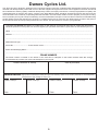
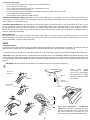
Dawes manual cover.pdf
31/10/08
13:58:01
C
M
Y
CM
MY
CY
CMY
K
Owner’s Manual
Dawes Cycles Ltd. 35 Tameside Drive Castle Bromwich Birmingham B35 7AG
Tel: 0121 748 8050 Fax: 0121 748 8060 www.dawescycles.com
INSTRUCTION MANUAL
AND GUARANTEE
WARRANTY
All bikes must be registered within 14 days of purchase either online or by post using the form that is
supplied with the cycle or on the Dawes website. Failure to do this will result in the warranty being void.
For 5 years
All rigid steel frames and forks
All rigid Titanium frames and forks
For 3 years
All rigid alloy frames and forks
For 1 year
All suspension frames
All paintwork and decals
All carbon fibre frames and forks
All original parts, suspension forks and rear suspension units unless these parts are covered in service by a
UK distributor. (See below)
Non-Dawes branded components
All non-branded Dawes components such as Rockshox, Shimano, Avid and SR Suntour are all covered by
the original manufacturer’s warranty.
Whenever a fault occurs to a non-Dawes branded product you should contact the UK distributor for that
brand to arrange a replacement or repair.
This warranty does not cover
Normal wear and tear
Improper assembly
Improper follow up maintenance
Installation of parts or accessories not originally intended for, or compatible with, the bicycle as sold.
Damage or failure due to accident, misuse, excessive load, abuse or neglect
Labour and transportation charges for part replacement or changeover
This warranty is applicable from the date of purchase for the original owner only, who must produce proof of
purchase and register their cycle in order to validate any claim. Claims must be submitted through your
original retailer, unless the original retailer is no longer trading or no longer a Dawes dealer. No bike is
indestructible and no claims will be accepted for damage due to improper use, competition use, stunt riding,
ramp jumping, leaping or similar activities. Our bikes conform to BS 6102/1: 1992 and BS EN 14766:2005
Mountain bicycles, BS EN 14764: City and trekking bicycles, BS EN 14781: Racing bicycles and EN14765:
Bicycles for young Children (size 435mm-635mm, seat height to ground).
The company reserves the right to change or amend any specification without notice. All information and
specifications within this brochure are correct at time of printing.
Please refer to our website for the latest information:
www.dawescycles.com
Dawes Cycles Ltd. 35 Tameside Drive, Castle Bromwich, Birmingham B35 7AG
Tel: 0121 748 8050 Fax: 0121 748 8060
2
Dawes Cycles Ltd.
This bike has been designed, developed and sourced, by Dawes Cycles Ltd. Castle Bromwich, Birmingham. Dawes has carefully
selected and developed this product with some of the best suppliers throughout the world. These suppliers have been checked &
have satisfied the exacting quality standards developed by Dawes, a company with almost a century long reputation for quality and
craftsmanship.All our bicycles are built to conform to the latest BS EN safety standards. Suspension frames and forks and rear
shock absorbers are covered by a separate guarantee.Included in this manual are details on how to prepare your bicycle for riding,
how to maintain your bicycle to keep it roadworthy, and recommendations and tips on how to achieve a safe and comfortable riding
position.Please ensure that the Bicycle Log below is completed at the time of purchase. The details will be of value to the police in
the unfortunate event should your bicycle ever be lost or stolen. This also acts as a record of your guarantee.
Complete this Section and keep it in a safe place In the
. event of your bicycle being lost or stolen this information
should be passed on to the police.You can also register your purchase with Dawes Cycles online at www.dawescycles.com
Name .....................................................................................................................................................................................
Address .................................................................................................................................................................................
...............................................................................................................................................................................................
Model Name & Type ..............................................................................................................................................................
Frame No ....................................Frame Size & Colour............................................................................................................
Extras and Identifying Marks .................................................................................................................................................
...............................................................................................................................................................................................
FRAME NUMBER
The frame number is located on the bottom of the seat tube or stamped on the bottom bracket shell. We strongly
recommend that you have your post code stamped on your bicycle.
Dealer’s Address or Stamp
Service Record:
Date of purchase
Highly Recommended for safety & support of warranty claims. At 6-monthly intervals or more frequently
if subjected to high mileage or heavy use.
Dealer Stamp:
Dealer Stamp:
Dealer Stamp:
Dealer Stamp:
Date:
Date:
Date:
Date:
3
YOUR BICYCLE — OWNER’S RESPONSIBILITY
In this leaflet we describe and illustrate how to ride safely and keep your bicycle in a safe, trouble free operating condition.
Owner’s Responsibility and Important Points
Your new Dawes bicycle is clearly marked to indicate that it has been manufactured to conform to one of four new
European bicycle safety standards , these standards have been developed and introduced into Europe and the UK to
ensure that bicycles manufactured in compliance with them will be as safe as is practically possible. please refer to the BS
EN sticker on your bicycle frame for the relevant safety standard.
BS EN14766; Mountain Bicycles.
BS EN14764; City and Trekking Bicycles.
BS EN14781; Racing Bicycles.
EN14765; Bicycles for young children.
Before you ride your bicycle ensure that you are fully aware as to the type of use and the specific BS EN safety standard that your new
bicycle has been designed and manufactured to by understanding the specific usage descriptions given below.
BS EN14766; Mountain Bicycles. (permissable total weight of rider + luggage + bicycle = 145kg)
These bicycles are intended for use off-road, on rough terrain such as coarse pebble tracks, forest trails, and other general off-road
tracks where tree-roots and rocks are likely to be encountered. The use of a bicycle off-road in hazardous conditions such as on
changeable and uneven surfaces can put very high unpredictable loads on the bicycle and its components. Lack of rider skill and
experience of these conditions can further increase these loads leading to the possibility of serious damage to the bicycle and injury to
the rider. Check with your dealer or manufacturer in regard to the suitability of your bicycle for such conditions and carry out more
frequent maintenance checks as advised within this manual.
BS EN14764; City and Trekking Bicycles. (permissable total weight of rider + luggage + bicycle = 145kg)
These bicycles are intended for use on public roads, paths or cycle tracks that are in good condition. Paths and cycle tracks can be
gravel or dirt roads with minor undulations and small potholes. Check with your dealer or manufacturer with regard to the suitability of
your bicycle for such conditions and carry out maintenance checks as advised within this manual.
BS EN14781; Racing Bicycles. (permissable total weight of rider + luggage + bicycle = 135kg)
These bicycles are intended for high-speed amateur use on public roads but are not to be considered as specialised
racing bicycles for use in sanctioned competitive events. Check with your dealer or manufacturer with regard to the
suitability of your bicycle for such conditions and carry out maintenance checks as advised within this manual.
EN14765; Bicycles for Young Children. (permissable total weight of rider + luggage + bicycle = 105kg)
These bicycles are intended for use by children on roads, paths and cycle tracks that are in good condition.Paths and cycle tracks can
be gravel or dirt roads with minor undulations.Children must, always ride within their own abilities and should wear a safety helmet at all
times.
Check with your dealer or manufacturer with regard to the suitability of your bicycle for such conditions and carry out
maintenance checks as advised in this manual.
• Carefully and thoroughly read this manual and follow the instructions. Your bicycle also comes with a manual pack
that includes component manufacturers supplementry sheets that cover features unique to your bicycle including
adjustment and general maintenance. Please ensure that you read and become familiar with their contents.
• Always wear a helmet approved to EN1078 when riding your bike, and follow the helmet manufacturer’s instructions for
fit, use and care.
• Please read and familiarise yourself with the Highway Code which contains useful information on safe riding on public
roads. www.direct.gov.uk
• Any major service or adjustments on your bicycle should be carried out by a professional repairer; however if this service
is not available and you wish to make adjustments yourself, this manual contains important tips on how to do it.
CAUTION: Any adjustments you make are entirely at your own risk.
• To use your bicycle for freestyle and stunt riding, competitive events, off-road use or any similar activities can be dangerous
and you are warned that you assume the risk for personal injury, damages or losses incurred from such use.The Retailer shall not be
liable to the purchaser of the bicycle or to third parties for consequential or special damages.
• Bicycles are built with a variety of equipment and accessories, and you should familiarise yourself with their function and purpose, to
make sure you can operate them correctly.
• Do not ride your bicycle when any part is damaged. Take your bicycle to a dealer if anything breaks or bends. If you
are unsure as to how to carry out repairs or maintenance on you bicycle it is vital that you consult a local dealer for
professional support.
WARNING: Warning. As with all mechanical components, the bicycle is subjected to wear and high stresses. Different materials
and components may react to wear or stress fatigue in different ways. If the design life of a component has been
exceeded, it may suddenly fail possibly causing injuries to the rider. Any form of crack, scratches or change of
colouring in highly stressed areas indicate that the life of the component has been reached and should be replaced.
4
LOCATION OF PARTS WITH ROUTINE MAINTENANCE
CHECKS AND LUBRICATION
B
R
Q
P
C
D
A
E
E
F
G
S
G
N
T
H
O
N
A - Headset
Remove, clean and regrease
bearings yearly, checking if
replacement is required.
B - Stem Nuts
Ensure stem nuts and bolts are
tight.
C - Handlebars
Check handlebar/stem bolts are
tight. Check brake levers are
securely mounted to bars and
brakes stop smoothly and
efficiently.
D - Brakes
Lightly oil exposed cables
monthly. Maintain adjustment and
replace brake blocks when worn,
brake cables when frayed.
E - Reflectors (front & rear)
Ensure reflectors are secure,
clean and undamaged.
Replace if necessary.
F - Front Suspension unit
(Dealer adjustment only)
M
L
K
G - Tyres
Check for cuts and wear. Maintain
pressure indicated on tyre wall for
maximum efficiency.
H - Wheel Reflectors
Check reflectors are clean and
securely fixed, monthly.
I - Disc Brakes - Front
(Routine maintenance by your
dealer recommended.)
J - Wheel Hubs
Grease bearings monthly. Adjust
cones to avoid free play from side
to side.
K - Pedals with Reflectors
Check all fittings are secure and
clean.
L - Cranks
Grease bearings monthly. Check
that axle bolts or cotterpin bolts
are tight. Check for free play in
bottom bracket.
M - Chain
Keep lightly oiled weekly, clean
and lubricate half yearly.
J
H
I
N - Wheels
Rims should be kept free from wax, oil,
grease, glue and checked for rim
damage or wear due to brake action.
Check rim wear line limit indicator. See
page 13.
O - Bottom Bracket
Clean, regrease yearly, checking for
wear.
P - Gears
Front and Rear — Lightly oil moving
parts. Maintain adjustments of front and
rear derailleurs.
Q - Disc Brake - Rear
(Routine maintenance by your dealer
recommended).
R - Seat and Stem Nuts
Be sure seat and
stem nuts are tight. See page 8.
S - Pedals
Lightly oil bearings monthly.
T - Frame Number
Refer to table of Recommended torque values - page 8.
Half Yearly — Remove and clean, lubricate chain, derailleur gears and all cables. Check and replace as required.
Yearly — Remove, clean and regrease hub axles, bottom bracket set and headset.
NB — Wash cycle weekly with warm soapy water and polish dry with a soft cloth. Do not pressure wash.
SAFE CYCLING AND SAFETY TIPS
Before you ride your bicycle at any time make sure it is in a safe operating condition. Particularly check that your:•
Bicycle’s nuts, bolts and parts are tight and not worn or damaged.
•
Riding position is comfortable.
•
Brakes are operating effectively.
•
Steering is free with no excessive play.
•
Wheels run true and hub bearings are correctly adjusted.
•
Wheels are properly secured and locked to frame/fork.
•
Tyres are in good condition and inflated to correct pressure.
•
Pedals are securely tightened to pedal cranks.
•
Gears are correctly adjusted.
•
All reflectors are in position.
After you have made any adjustments to your bicycle, check that all nuts and bolts are securely tightened and cables are
free from kinks and fixed securely to the bicycle frame.
Every six months (more frequently if high mileage or subject to heavy use) your bicycle should be professionally checked
to ensure that it is in correct and safe working order. A ‘Service Record’ is provided for your use.
5
To ensure your safety:
•
Do not ride on the same side of the road as oncoming traffic.
•
Do not ride two side by side.
•
Do not carry a passenger unless cycle is equipped to do so.
•
Do not swerve in and out of traffic.
•
Do not hang items over the handlebars to impede steering or catch in the front wheel.
•
Do not hold on to another vehicle.
•
Do not ride too close behind another vehicle.
CAUTION: Wet Weather Riding No brakes work as well under wet or icy conditions as they do under dry conditions. In
wet weather special precautions must be taken to assure safe stopping. Ride slower than normal and apply your brakes
well in advance of anticipated stops.
CAUTION: Night Riding We recommend you minimise the time you ride after dark. If you should have to be out on your
bicycle at night you must comply with the law, use a headlight (white) and a tail-light (red) on your bicycle in addition
to the all-around reflectors that are fitted. For added safety wear light coloured clothing with reflective stripes.
Check that the bicycle reflectors are firmly secured in their correct position, clean and not obscured. Damaged reflectors
must be replaced immediately.
Riding Position
It is important that you and your bicycle are fitted to each other, not only for comfort and riding ease but for control and
safety. Normally your Dealer will custom fit your bicycle to you but the following few pages should help you to find your
most comfortable, safe and efficient position.
SEAT
Seat Adjustment
Loosen the nut on the seat-post clamp enough to allow the saddle to move backwards or forwards. The seat can then be
aligned and the angle can also be adjusted (it is recommended that the seat be parallel to the ground).
To adjust the seat up and down, loosen the binder-bolt on the seat tube, position the seat and re-tighten the binder-bolt.
CAUTION: Insert the seat-post to a point above the insertion mark. The MINIMUM INSERTION MARK should not be
visible. Securely tighten the seat-post binder bolt/nut by using an Allen key or a 13 mm spanner. Test by grasping the seat
and attempting to turn. Keep tightening until the seat will no longer turn. Refer to table of recommended torque values on
page 8.
WARNING: Bicycle should not be ridden if seat adjustments are not properly tightened.
Allen head
Binder-bolt
Saddle
Seat Post
Seat tube
Seat
posts
differ
according to saddle
types and accordingly
the procedure for fitting
varies. If in doubt consult
your dealer.
Minimum
Insertion mark
Normal 13mm
Binder-bolt
End of
Seat Post
Seat Angle
Se
or Bat For
ack war
war ds
ds
Close
Open
6
Seat Post adjustment— Suspension
frames.Take care when inserting seat post
that the protruding end cannot interfere with
the frame suspension unit during use. If in
doubt consult your dealer about adjustment.
CYCLING POSITION — Seat
Saddle Angle
The seat should be horizontal or parallel with the ground. Slight variation around the horizontal may suit individual comfort
but if excessive angles are felt necessary check other aspects of your position.
Saddle Height
The correct seat height is determined by sitting on the seat with your leg fully extended. Your heel (in flat shoes) should
just touch the pedal when it is positioned at its lowest point. When riding normally with the ball of your foot on the pedal
your knee should be slightly flexed at the bottom of the pedal stroke (see diagram following).
Saddle Forwards/Backwards Position
With the ball of one foot on the pedal and the cranks parallel to the ground the saddle should be adjusted backwards or
forwards to a position whereby the pedal centre is directly below the knee joint.
Very small changes in saddle position can have a substantial effect on performance and comfort. Consequently,
whenever you make a change to your saddle position, make only one directional change at a time and make the
changes in small increments, until you have found the point at which you are most comfortable.
Knees slightly
bent
Loosen saddle from seat
post to adjust forwards
or backwards. Tighten
when set correctly
Handlebar Stem
approximately level
with seat or slightly
lower
Pedal at bottom
position
The saddle should be moved forwards or backwards so that the
knee is directly above the pedal when the crank is parallel to the
ground.
HANDLEBARS AND STEMS
As your cycle may be fitted with a standard ‘quill’ stem or an A-Head stem, you must check that all the bolts are tight before
cycling.
STANDARD STEM: Loosen expander bolt so that expander wedge is not tight in bottom of handlebar stem. Gently tap the top
of the expander bolt to further loosen the wedge, if necessary. When the expander wedge is loose, move the handlebars up or
down until you find the optimum height at which you can easily reach the brake levers and comfortably grasp the handlebars.
Usually this height is level with, or slightly lower than, the top of the saddle. Be sure the stem is in line with the front wheel.
CAUTION: A minimum insertion ring is marked on the handlebar stem and this marking should remain in the head
tube. Under no circumstances should the minimum height insertion mark be visible on the handlebar stem. It must
be down in the head tube.
When desirable height has been achieved, align the handlebar with the front wheel and securely tighten expander bolt. It is
extremely important to tighten the expander bolt sufficiently, so that when the wheel is held between your legs and the
handlebars are twisted, the handlebars do not move. Do not over tighten, as it may increase risk of injury to the rider. Position
grip portion of handlebars horizontally and securely tighten the binder bolt.
Refer to table of recommended torque values on page 8.
Note: Whenever the handlebar stem is removed from the head tube then the expander bolt should be lightly greased.
Note: On some bike’s raising the stem requires brake cable adjustment. Do not attempt this if low profile brakes are fitted
with a stem mounted cable stop.
A-HEAD STEM: Has 2 steerer clamp bolts on the back of the stem, which clamp around the steerer tube. Loosen these bolts
to align the stem with the front wheel. Re-tighten the steerer clamp bolts.
CAUTION: Do not adjust the top compression bolt, this should be pre-set to eliminate bearing play, overtightening will cause
premature wear.
Contact your retailer for service.
7
Standard Quill Stem
A-Head Type
Recessed Type
6mm Allen Key
Compression Bolt
5 Star Washer
Stem Binder
Bolts
Steerer
Clamp Bolts
Handlebar
Stem Expander
bolt
Compression Cap
Extension
Stem Expander Bolt
(Allen Head)
Spacers
Bearing Seat
Stem
Binder
Bolt
Minimum
Insertion
Mark
Top cup with Bearings
inside
Handlebar Position
The position of the handlebar should be set to allow a comfortable and easy reach of both gear control and brake levers.
When riding, your weight should be so balanced that your hands rest lightly on the handlebars. This prevents strain on
wrists and forearms when pedalling. If you alter the riding position, remember to tighten all nuts and bolts securely.
Refer to table of recommended torque values below.
CAUTION
NEVER EXTEND THE HANDLEBAR STEM OR SEAT POST ABOVE THE MINIMUM INSERTION MARK AS THIS IS
DANGEROUS
COTTERLESS CRANKS ADJUSTMENT
IMPORTANT
To ensure trouble free operation it is important that the nuts securing the lefthand and righthand chainwheel to
the bottom bracket axle are tightened as securely as possible.
It is strongly recommended that the tightness of the nuts be checked after the first two weeks of use and a
maximum of three monthly intervals thereafter.
TABLE OF RECOMMENDED TORQUE VALUES
2
1
13
12
11
10
9
DESCRIPTION
Stem Expander Bolt
(where fitted)
1A A-Head Steerer Clamp Bolts
(where fitted)
2
Stem Binder Bolt
1
3
1A
4
3
7
6
8lb-ft
5Nm
4lb-ft
30Nm
22lb-ft
5
Chain Wheel Securing Bolt
38Nm
28lb-ft
6
Pedal
40Nm
30lb-ft
7
F/Derailleur Cable Fixing Bolt
4Nm
3lb-ft
8
R/Derailleur Cable Fixing Bolt
4Nm
3lb-ft
9
Rear Axle Nut
30Nm
22lb-ft
10
Seat Pin (Hexagonal Head)
20Nm
Seat Pin (Allen Head)
15Nm
Front and Rear
3Nm
Reflector Mounting Nut
Saddle Clamp Bolt (Hexagonal Head)
20Nm
Saddle Clamp Bolt (Allen Head)
10Nm
F/Derailleur Clamp Bolt
5.5Nm
15lb-ft
11lb-ft
2.5lb-ft
13
8
8lb-ft
10Nm
Brake Fixing Bolt (non disc)
Applies to both front and rear brake
Front Axle Nut
12
5
10Nm
4
11
8
TORQUE
20Nm 15lb-ft
15lb-ft
8lb-ft
4lb-ft
BRAKES
WARNING
For safe riding it is important to completely understand the operation of your bicycle’s brake system. Improper use of
your bicycle’s brake system may result in a loss of control or an accident, which could lead to severe injury. Because
each bicycle may handle differently, be sure to learn the proper braking technique (including brake lever pressure
and bicycle control characteristics) and operation of your bicycle. This can be done by consulting your professional
bicycle dealer and this owner’s manual, and by practicing your riding and braking technique.
The bicycle is equipped with two independant brake mechanisms. One on the front wheel and the other on the rear
wheel. The brakes are operated by hand levers fastened to the handlebars. The right lever controls the front brake and
the left lever controls the rear brake.
To stop with safety:
1. Operate the rear brake (left lever) slightly before the front brake (right lever).
2. Apply firm pressure to both front and rear brake levers.
CAUTION: If the front brake is applied with too much pressure, the rider may be thrown off the bicycle.
3. Never apply the front brake on a turn. This is especially dangerous when cornering or riding on slippery or loose
surface roads.
CAUTION: Brakes are less effective in wet weather. Ride slower and allow more distance for stopping.
Note: Do not ride your bicycle if the braking system is not working correctly. If you are in doubt, take your bicycle to
your dealer.
Note: The information provided below is for the adjustment of caliper brakes. For other brake systems please see
manufacturer’s manuals provided.
BRAKE ADJUSTMENT PROCEDURE — Caliper brakes
The brakes on your bicycle should have been adjusted correctly by your dealer. However, as cables do stretch, it is
important to check the adjustment of your brakes after your first ride. Most brakes will need some adjustments after being
used the first few times. Your brakes are correctly adjusted when there is a 1.5 mm gap between the brake blocks and the
brake track of the wheel rim.
Do not adjust brakes to allow brake blocks to contact wheel rim when brake levers are in the off position. The fine
adjustment of the brakes is made by the following procedure:
1. Turn adjustor A to set blocks C just clear of rim by 1.5 mm.
2. Ensure that the brake blocks meet the rim parallel and central to the rim brake tracks. Adjust by nuts D if necessary,
then tighten securely.
3. When all fine adjustment is taken up on adjuster A, it will be necessary to reset the cables as follows:
a. Turn adjuster A all the way down as far as it will go into its mounting.
b. Loosen cable clamp bolt B. Press both brake shoes firmly against wheel rim.
c. Pull brake cable wire through its clamp bolt.
d. Tighten cable clamp bolt B securely.
Note: If one brake shoe is closer to the rim than the other first check that the wheel has been centred between the forks
then adjust the brakes as necessary.
To adjust brakes that have central Caliper adjuster simply turn screw as shown until brakes centralise.
9
BRAKE MAINTENANCE — Caliper brakes
To maintain cable brakes in efficient working order, regularly check the brake adjustment and lightly lubricate brake pivots
and springs. Oil the exposed parts of the innerwire to prevent corrosion. Slow or inefficient braking often indicates that the
brake cables themselves require lubrication or replacement. As this job requires the removal of the complete brake cable,
we recommend strongly that this service is done professionally.
Note: To assure smooth braking, wheels must run true and be correctly adjusted, with the rim brake tracks free from
dents and kinks. The brake blocks should be in correct alignment with the rim brake track. See your dealer if you are in any
doubt regarding wheel and brake adjustment.
Protect yourself from frayed cable ends by maintaining the alloy end caps fitted over the inner wire ends.
Brakes should function freely and release fully. If brakes bind, first check for clean-liness and proper lubrication. If brakes still
bind, return your bicycle to your dealer for adjustment.
Calliper Arm
Return Spring
Tyre
Quick Release
Mechanism
Wheel Rim
Brake Shoe
Brake Shoe
To centre side pull brakes first slacken the retaining nut and then centre the brake using a spanner on the front retaining
nut.
CAUTION: Before riding, test your brakes. Make sure that the quick release mechanism is returned to its normal correct
position, otherwise your brakes will not operate effectively.
BRAKE BLOCK REPLACEMENT- Caliper and V Brakes
All brake blocks are provided with grooves that indicate the wear on each block.
When the grooves are worn down to a flat surface, replace the blocks (in pairs)
immediately.
Wear Indicator Groove
‘V’ BRAKE SYSTEM
INNER CABLE QUICK RELEASE
To release the brake inner cable from the V brake, squeeze the two brake arms together until the brake blocks contact the
rim and remove the inner cable pipe from the cable end bracket.
To re-connect again squeeze the two brake arms together and relocate the inner cable pipe in the cable end bracket.
INNER CABLE ADJUSTMENT
1. Pass the inner cable through the inner cable lead, and after setting so that the
total of the clearances between the left and right shoes and the rim is 2 mm,
tighten the cable fixing bolt.
2. Adjust the balance with the spring
tension adjustment screws.
Inner Cable Lead
Pipe
Cable End
Bracket
3. Depress the brake lever about 10 times as in normal brake operation and check
that everything is operating correctly and that the shoe clearance is correct before
using the brakes.
BRAKE MAINTENANCE — Disc Brakes
Cable Fixing
Bolt
Depress about
10 times
Your cycle may arrive with factory fitted disc brakes — the latest technology in cycle braking!
If you have purchased your cycle from a professional cycle shop your brakes should have been set up correctly. You will
only have to do routine maintenance as the brake pads wear.
If you purchased your cycle from a mail-order source you may have to set up the brakes before you use your cycle.
Please refer to the disc brake leaflet that accompanies the cycle. If you do not have such a leaflet please take your cycle
to a professional cycle shop.
10
DERAILLEUR GEARS
INTRODUCTION
The derailleur gear is so named because it works on the derailing principle to move the chain from one sprocket to
another. The number of gears is determined by multiplying the number of sprockets on the rear freewheel by the number
of chainrings on the front crank set.
By using different combinations of sprocket and chainwheel sizes, a wide range of gear ratios are available. The highest
gear is when the large chainwheel is coupled with the small sprocket and the lowest gear is when the small chainwheel
is combined with the largest rear sprocket.
The wide range of gears allows you to attempt all prevailing conditions while pedalling at the constant and efficient rate of
sixty revolutions per minute.
DERAILLEUR GEAR MAINTENANCE
To help ensure that your derailleur gear works efficiently and to prolong its life, it must be kept clean and free from excess
dirt build up and should be properly lubricated.
GEAR CHANGING
The rider’s left gear lever controls the front derailleur and chain wheels. The function of the front derailleur is to move the
chain between the larger and smaller chain rings.
The rider’s right gear lever controls the rear derailleur and sprockets.
The function of the rear derailleur is to move the drive chain from one gear sprocket to another.
The large rear sprockets generate low gears for hill climbing. The small rear sprockets develop high gear ratios for speed
work and downhill riding.
The small front chainring produces low gear ratios while the larger front chainrings produce higher gear ratios.
To operate your derailleur gear system efficiently and reduce damage, wear and reduce noise to a minimum, avoid using the
maximum crossover gear ratios of large chainring/large rear sprocket, small chainring/small rear sprocket.
CAUTION: For positive gear selection, observe these four precautions:
1. Change only when pedals and wheels are moving in a forward motion.
2. Reduce pedal pressure while changing gears.
3. Never back pedal when changing gear.
4. Never force the gear levers.
Gear selection should be made in anticipation of need since forward motion of the bicycle is required when changing gear. It
is advisable to change to a low gear before stopping in order to be in the proper gear when you start up. On hills, change gear
early while still maintaining forward pedalling speed.
Note. To understand the function and to carry out adjustments and maintenance of the unique gear system fitted on your
bicycle please refer to the manufacturer’s leaflets provided within your manual pack.
SUSPENSION
Your cycle may be fitted with suspension units built into parts of the frame and forks. We recommend these are only
serviced by your dealer as required. More details may be found in the suspension manufacturer’s handbook.
Front Suspension Unit
Bottom Bracket Height
Frame Suspension Unit
Pre Load Adjust
Pre Load Adjustment
We recommend that for optimum safe riding Pre-Load should be set as follows.
1
Pre-Load alters the amount of bottom bracket drop when seated on the saddle. We strongly recommend you
set Pre-Load so as to experience no more than 1" (25mm) of sag. Measured as a decrease in bottom bracket
height.
To adjust Pre-Load, grasp knurled adjuster (A) and spring, and either:
2
3
Increase Pre-Load by turning to compress the spring
Decrease Pre-Load by turning to allow spring extension.
11
TYRE CARE AND WHEEL ADJUSTMENTS
To obtain maximum life and full benefit from your tyres, it is essential to maintain the recommended pressure indicated on
the tyre sidewall. Unnecessary hard braking and skidding greatly reduces tyre life. Make sure your tyres do not come into
contact with oil, petrol, paraffin or other rubber solvents. Make sure that your wheels run true and are in correct alignment
to avoid chafing the tyre sidewall against the bicycle frame or fork tubes. Tyres should regularly be inspected for wear and
cuts. Check that the tyre tread pattern is clearly showing all around the outside edge of the tyre. Check there are not any
breaks, cuts or uneven wear in the tyre. Tyres should be replaced if damaged. Tyre punctures can be caused by careless
riding over sharp stones, holes in the road, or by hitting curbstones. If you are storing your bicycle for a long period of
time, it is advisable to store the machine with the tyres off the ground to prevent them from becoming distorted. To inflate
tyres, a foot pump or normal bicycle inflator fitted with a suitable valve connector should be used along with an accurate
tyre pressure gauge. Wheels should be checked regularly for spoke tension. Perform this check more frequently if the
bicycle is used on rough roads.
Front wheels
Caution:
Your front wheel comes with a retention device to keep the wheel axle from
Nut
disengaging from the fork-ends if the wheel nuts or the quick-release are
incorrectly assembled. These devices are of two types.
1: Small protrusions machined or formed on the outer face of the fork-ends.
2: Shaped washers that contain a small tab/prong that engages in a hole
within the fork-end.
FRONT WHEEL REMOVAL AND REPLACEMENT
Nut
Retention device or standard washer
Disengage the brake quick release lever if your bicycle is so equipped.
Loosen both axle nuts by turning in a counter clockwise direction. Remove
axle nuts, washers, and axle retention device if fitted. Remove the front
Nut
wheel. The axle cone bearing adjustment should permit smooth rotation of
Axle
wheel with the cone locknut securely fastened against axle cone to prevent
loosening.
Replace the front wheel between the fork blades ensuring that the projecting Retention
tab/prong of the retention device are securely fitted into the slot in the fork washer
ends or with standard washers securely in position butting against the (if fitted)
protrusions on the fork end. Securely tighten all wheel nuts ensuring that the
wheel is central within the forks. Refer to page 8 for recommended torque
Front Fork
settings.
Note. Reset brake quick release mechanism and check brake for proper
operation.
Front Hub
Cone
Cone Locknut
To Remove Rear Wheel
Move the chain onto the smallest rear sprocket. Disengage the brake quick release lever if your bicycle is so equipped.
Loosen both axle nuts by turning in a counter clockwise direction. Pull the derailleur mechanism gear rearwards for
additional clearance. Remove the rear wheel by sliding forward or down and out of the frame.
To install wheel, locate the top section of the chain on the small sprocket and replace the wheel into the frame by pushing
back and centralising between the chainstays. While holding the wheel in this position, tighten the axle nuts in a clockwise
direction securely ensuring that the wheel is central within the chainstays. Refer to page 8 for recommended torque
settings.
The wheel should turn freely and have no side play.
Reset rear brake quick release mechanism and check brake for proper operation.
ADJUSTMENTS
QUICK RELEASE FRONT WHEEL
1. To remove the front wheel, first release the front wheel brake. Then open the quick release lever on the axle and pull
the wheel from the forks.
2. To install, fit wheel into forks with quick release lever on the left side. Close quick-release, and tighten adjuster until
snug. Release quick-release lever and further tighten adjuster approximately 3/4 of a turn. Lock and check that
the quick-release has embossed the fork ends. It may be necessary to tighten or loosen the adjuster slightly.
Note. Reset brake quick release mechanism and check brake for proper operation.
3. Wheel must be clear frame and fork by at least 1-5mm.
4. The wheel should turn freely and have very little side-play.
5. Check quick release lever is in the correct and fully locked position before each ride.
Adjusting nut
Spring
Retaining Device
Open
Spring
Quick Release Lever
12
Closed
Locked position
Quick Release Rear Wheel
Removal and installation of rear wheel fitted with quick release mechanism. Use same procedure as for standard rear
wheel, with the exception of loosening axle nuts. Operate the quick release lever by pulling away from the wheel 180° to
release the wheel.
When installing the rear wheel, position the wheel centrally in the frame, folding back the lever, then, when in position fold
the lever into its closed position.
Check quick release lever is in the correct and fully locked position before each ride.
Reset rear brake quick release mechanism and check brake for proper operation.
RIM WEAR LINE LIMIT INDICATOR
If your bicycle is fitted with disc brakes to the front and rear the following explanation is not applicable and can be ignored.
There are two types of safety warning line on the wheel rims, please check which version is fitted to your bicycle and note
the relevant instructions which follow.
Concealed Safety Line
This type of safety line is not visible as it has been constructed within the aluminium braking surface. When the rim has
been subjected to extended braking and the rim surface is sufficiently worn to warrant replacement, the safety line will
appear in the rims braking surface. This can be recognised as a 1mm groove in the centre of the braking surface.
THE RIM MUST BE REPLACED BY A PROFESSIONAL CYCLE MECHANIC BEFORE THE BIKE IS RIDDEN.
Visible Safety Line
This type of safety line is already machined and is visible in the aluminium braking surface. When the rim has been
subjected to extended braking and the rim surface is sufficiently worn to warrant replacement, the safety line will
disappear and the rims braking surface will be one continuous smooth surface.
THE RIM MUST BE REPLACED BY A PROFESSIONAL CYCLE MECHANIC BEFORE THE BIKE IS RIDDEN.
WARNING! Do not attempt to ride the cycle until you are absolutely sure that all quick release levers are fully closed
and securely tightened.
FITMENT OF BELL
1.
2.
3.
4.
Brake Lever/Shifter
Remove screw from bell clamp.
Position in a convenient spot near the left hand or right hand handlebar grip.
Replace screw & tighten securely.
Rotate the “Ping Arm” to a comfortable position.
WARNING
Grip
Ping Arm
Position Bell on left hand or right
hand side of the handlebar as
required.
L
R
L
R
Check for the letters “L” or “R” on the ends of the pedals to show which side the pedal needs to be fitted to.
TO FIT RIGHTHAND PEDAL
1.
2.
3.
Tighten Clockwise
R
TO FIT LEFTHAND PEDAL
4.
1.
2.
L
3.
Tighten Anti-clockwise
13
4.
Fit to chainside of cycle.
The pedal tightens in a
clockwise direction,
towards the front of the
bicycle.
Locate thread by hand, fit
and tighten.
Use spanner to finish
tightening (be careful)
Fit to non chainside of cycle.
The pedal has a special
thread to tighten in an anticlockwise direction,
towards the front of the
bicycle.
Locate thread by hand, fit
and tighten.
Use spanner to finish
tightening (be careful)
Maintenance
Dawes Cycles recommends your new bike is checked and serviced at regular internals to ensure its performance,
reliability and your safety.
Wherever possible we recommend that service, maintenance and repairs are undertaken by your local dealer. If this is
not possible please review the following detail as a guide.
A list of appointed & recommended dealers is available at: www.dawescycles.com
Maintenance Checklist
Before each ride
• Check both wheel axles are secure in the frame & forks.
• Check tyres are within the recommended pressure limits as indicated on the side wall. It is good practice to carry
tyre levers and a puncture repair kit at all times.
• Check handlebar assemblly is tight and rotates freely.
• Check the function of the braking system whilst stationary.
• Check the gear shifters operate correctly.
• Rotate each wheel ensuring it rotates freely.
• Check the saddle and seat post is secure and adjusted.
• Check the pedals are secure and the chainwheel crank arms are free of lateral movement.
• Check lights, reflectors and bell are all in good working order.
Monthly and after long or hard rides, the following additional checks/maintenace should be completed.
• Clean degrease and lubricate your bike.
• Inspect tyres for wear, damage and punctures.
• Check no spokes are loose, broken or missing.
• Hubs run smoothly with no sideways play.
Annual service and inspection
If you have any doubts about completing the following service and inspection you must seek the services of the
professional cycle technician at your local dealer. You can find your nearest dealer at www.dawescycles.com (off road
riding will require more frequent maintenance.) It is good practice before commencing any service/inspection to
thoroughly clean and degrease your bicycle.
Inspect
• Frame, forks and suspension parts for damage, cracks, corrosion and deformation.
• Wheels for damage, balancing, spoke tension and rim wear.
• Brake levers, brake blocks/pads, brake control cables and inner wire.
• Chain for corrosion, stiff links & stretch. (failure to maintain the chain will considerably reduce the performance
and life span of the whole gear system).
• Chainwheel cranks are securely fastened to the axle at the correct torque.
• Front and rear gears for damage, wear and alignement.
• Disassemble headset, clean, regrease and reassemble making sure to inspect bearings for wear.
• Remove seat post from frame clean and regrease before refitting.
Suspension and hydraulic brakes must be serviced by your local dealer.
Any component found to be damaged or worn must be inspected by a professional and replaced where necessary with
genuine replacement parts.
14
Cleaning and lubrication
Dawes Cycles recommends the use of Weldtite cleaners and lubricants www.weldtite.co.uk
This website has a “short course” in maintainance for all the basic skills & equipment you will need to keep your bike in
tip top condition.
Regular washing and lubrication not only keeps your bicycle looking in top condition but will actually assist in
maintaining its original performance and prolongs the life expectancy of the mechanical components.
The chain is the most important component to keep clean as it is the part that wears the teeth on the rear sprocket, the
rear gear and the chainset. It is also the key part which transfers your effort into forward motion. If it is clean it is efficient
and it is not damaging the gear system.
1
Monthly
2
Bi-Annually
3
Annually
2
3
3
1
3
3
1
1
1
2
2
2
2
2
15