1
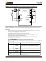
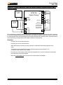
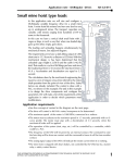
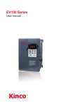
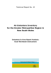
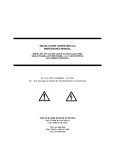
www.saftronics.com
START-UP PROCEDURE
FOR THE GP5 / FP5
TABLE OF CONTENTS
INSTALLATION
EXAMPLE 1:
Start/Stop & Speed Changes via the Keypad
(Out of Box)
EXAMPLE 2:
Remote Start/Stop (2-wire) & Speed Changes
via Keypad
EXAMPLE 3:
Remote Start/Stop (3-wire) & Speed
changes via the Keypad
EXAMPLE 4:
Remote Start/Stop (3-wire) & Speed Changes
via a Remote Source
EXAMPLE 5:
Remote Start/Stop (3-wire) & Speed Changes
via the Speed Pot
EXAMPLE 6:
Remote Start/Stop (2-wire) & Speed Changes
via external source with 3 Present Speeds
ADJUSTING THE TRIM POT.
WARNING
Saftronics, Inc.
5580 Enterprise Pkwy., Ft. Myers, FL 33905
Telephone: (941) 693-7200
Fax: (941) 693-2431
PAGE
2
4
5
6
7
8
9
11
P/N 027-2073
START-UP GUIDE
GP5 / FP5
www.saftronics.com
Start-Up Procedure for the GP5/FP5
The following procedure is to assist in the start-up of the GP5/FP5 inverter, by providing a step by step
guide to installation, programming and basic operation of the GP5/FP5 inverter. The procedure is
based on several common configurations used in the industry. For more detailed configurations and
applications refer to the GP5/FP5 instruction manual (Part # 027-2005F) available at www.saftronics.com.
Installation
1.
Verify that the input voltage of the supply, motor and the drive model number are all marked with the
same voltage. Caution: If improper voltage is applied to the inverter, severe damage will result.
2.
Mount the inverter on a vertical surface with adequate space for proper air circulation (minimum 1.18
inches on each side and 4.72 inches above and below; (Instruction Manual Page 17).
3.
Remove the front cover, connect conduit to the bottom plate, and connect power and ground wires to the
correct terminals.
Caution: Connect correct input voltage to terminal L1, L2, and L3.
Connect motor to terminals T1, T2 and T3 only or severe damage will result.
4.
Replace the cover and apply voltage to the inverter. The keypad will display “Frequency Ref.
U- 01=0.00Hz”; Drive, SEQ, REF & Stop LED’s should be illuminated on the keypad. Pressing the
Local/Remote key will turn off the SEQ and REF LED’s and put the inverter into local mode (keypad
control). By pressing the RUN key and holding s key until U-01= 6Hz is displayed, and then pressing
the ENTER key, will enable you to check the rotation of the motor. If the rotation is incorrect remove
power from the inverter, wait for the Charge LED to go out and then swap motor leads T1 and T2 and
then repeat step 4 to verify the rotation is correct on the application.
5.
Keypad - To access any parameter, press the DSPL key until “parameter” is displayed on the LCD
readout. Use the s and keys until the desired parameter is displayed then press ENTER. To change
the value in the parameter simply use the s and t keys and press ENTER to accept that changed
value.The keypad will then display END, to signify that the inverter has accepted the changes. For
additional programming instructions on the keypad see the GP5/FP5 Instruction Manual, part # 0272005F available at www.saftronics.com.
© 2000 Saftronics, Inc.
Page 2
START-UP GUIDE
GP5 / FP5
www.saftronics.com
Frequency Ref.
0.0 Hz
Home Position
Monitor U-01
Frequency Ref
Accel Time 1
0.0 Sec
Output Frequency
0.0 Hz
Decel Time 1
0.0 Sec
Output Amps
0.0 A
U-01 Frequency Ref
U-02 Output Frequency
U-03 Output Current
U-04 Output Voltage
U-05 DC Bus Voltage
U-06 Output Power
U-07 Input Term. Status
U-08 Inverter Status
U-09 Past Four Faults
U-10 Software Revision
U-11 Elapsed Time Meter
U-12 Elapsed Time Meter
U-13 PID Feedback value
U-15 Kilowatt-hour Meter
U-16 Kilowatt-hour Meter
Input Voltage
230.0 VAC
Output Power
0.0 Kw
V/f Selection
60Hz Preset
Forward/Reverse
For
= DSPL key
Terminal FV Gain
100%
Terminal FV Bias
0.0%
Motor rated FLA
xx.xA
PID Mode
Disabled
Energy Sav Sel
Disabled
Parameter n002
Oper Mode
Select
Home Position
6. Choose a Configuration from the table below, each example listed below contains a control wiring
diagram, operation explanation, and all the necessary programming (associated with that mode). The
GP5/FP5 inverter can be controlled in several more modes than explained in the start-up guide. The
following configurations are generally considered the most commonly used in the field. For a more
complete explanation, please refer to the GP5/FP5 Instruction Manual part # 027-2005F or download a
copy from our website, www.saftronics.com.
Table A: Inverter Configuration Examples
S eq u en ce
(Start/Stop)
Reference
(Speed
C h an g es)
Keypad
Keypad
No control wiring needed to perform inital start-up
and check rotation of the motor.
Example 1
P age 2
2-wire
Keypad
Start/Stop via the remote contact (PLC), speed
changes via the keypad .
Example 2
P age 3
3-wire
Keypad
Start/Stop via the remote pushbuttons, speed
changes via the keypad.
Example 3
P age 4
2-wire
4 to 20mA
Start/Stop and speed changes from a remote source
such as a PLC.
Example 4
P age 6
3-wire
0 to 10Vdc
(Speed Pot.)
Start/Stop via the remote pushbuttons, speed
changes via a remote speed pot. or external source
(0 to10Vdc).
Example 5
P age 7
2-wire
Contact
Closures
Start/Stop via the remote contact (PLC) and speed
changes via present speeds or analog reference.
Example 6
P age 9
Description
Example
P ag e
7. Control Terminal Wiring- Remove power and wait until the Charge LED goes out before making control
connections. The size of the control wiring should be between 16AWG and 20AWG wire. All control
wiring should be shielded, with the shield grounded to the inverter’s chassis ground and the other end
left unconnected. All the control wiring terminates on the terminal strip located on the control card (the
card that plugs into the keypad).
© 2000 Saftronics, Inc.
Page 3
START-UP GUIDE
GP5 / FP5
www.saftronics.com
Example 1: Start/Stop & Speed Changes via the Keypad (Out of Box)
When the inverter is set up with the sequence (start/stop) and the reference (speed changes) via the keypad, that
is considered local mode. Local mode is generally used during initial start up or to check the rotation of the motor.
The inverter can be easily put in into local mode by pressing the LOCAL/REMOTE key. When the inverter is in local
mode the SEQ and REF LED’s are not illuminated on the keypad. If power is removed and then restored, the
inverter will come up in remote mode (SEQ and REF LED’s are illuminated).
Note:
The inverter can be placed in local mode by changing the programming (N002= SEQ-OPR , REF-OPR).
For a more detailed explanation, refer to the Instruction Manual (Page 37 part # 027-2007F).
Operation
The frequency ref.(speed change) is programmed into parameter U-01 (Frequency Ref.).
The inverter can be started by pressing the RUN key on the keypad.
The inverter can be stopped by pressing the STOP key on the keypad.
The direction of the motor can be changed, regardless of the motor speed, by pressing the DSPL key until
Forward/Reverse is shown on the LCD readout, and then use the key to change the value, then press
the ENTER key to change the direction of the motor.
s
Table 1: Programming needed for Local Mode (Keypad control)
Parameter
N002
Display Text
Oper Mode Select
SEQ=OPR REF=OPR
Description
Sets the frequency via the keypad and sets the start/stop via the
keypad.
N018/19
Accel Time
Decel Time
Acceleration Time and Deceleration Time/ From stop to full
sp e e d .
N033
Motor Rated FLA N033=
X.XA
Enter Full load amps from the motor nameplate data (This sets
the motor protection level).
Frequency
Ref.
Frequency Ref
U1-01=XX.Hz
Sets the desired frequency reference (speed). Settable by
pressing DATA/ENTER. Use the
and
arrow keys to set the
frequency and then press DATA/ENTER.
Forward/
Reverse
Forward/Reverse
F or
s
t
With this display, the motor direction can be changed
regardless of motor speed.
Note: After the changes are made, the DRIVE, SEQ and STOP LED’s will be lit.
© 2000 Saftronics, Inc.
Page 4
START-UP GUIDE
GP5 / FP5
www.saftronics.com
Example 2: Remote Start/Stop (2-wire) & Speed Changes via Keypad
S1
FS
GP5/FP5
Control Wiring
FC
S2
(K1) Forward
(K2) Reverse
S3
S4
S5
For more info on
the multi-function
inputs ref. page 78
in the GP5/FP5
Instruction manual
G
S6
Shield to
Terminal G
SC
FI
FV
This configuration is used when the Start/Stop is via an external source such as a PLC or relay. It can also be used
with a maintained switch when it is desirable to have the inverter restart on the return of power. It should not be used
where the safety of personnel might be threatened by the restart of the machine.
Operation
Frequency reference (speed change) is programmed into parameter U-01 ( see table 2 for details).
Close (K1) to run in the forward direction at the speed set in U-01.
Close (K2) to run in the reverse direction at the speed set in U-01.
When both relays (input) are closed, the inverter will display an EF (External Fault) error.
When the LOCAL/REMOTE key is pressed, the inverter will act as Example 1.
Table 2: Programming needed for remote Start/Stop (2-wire) and Speed
Changes via the Keypad
Parameter
Display
N001
Password
8
The inverter will perform a 2-wire reset.
CAUTION: This parameter sets all parameters to their factory settings and
all previous settings will be lost. When the inverter completes the reset,
the parameter returns to a value of 1.
N001
Password
3
Change to a value of 3 to access all parameters in the inverter.
N002
Oper Mode Select
SEQ=OPR REF=OPR
Description
Sets the frequency via the keypad and sets the start/stop via the keypad.
F LA
Motor Rated FLA
x.x A
Enter the full load amps from the motor nameplate (this sets the motor
protection level).
U1-01
Frequency Ref
U-01=XX.Hz
Sets the desired frequency reference (speed). Settable by pressing
DATA/ENTER. Use the Ù and Ú arrow keys to set the frequency and then
press DATA/ENTER.
Forward/
Reverse
Forward/Reverse
F or
With this display, the motor direction can be changed regardless of motor
sp e e d .
Note: After the changes are made, the DRIVE, SEQ and STOP LED’s will be lit.
© 2000 Saftronics, Inc.
Page 5
START-UP GUIDE
GP5 / FP5
www.saftronics.com
Example 3: Remote Start/Stop (3-wire) & Speed changes via the Keypad
(PB1)
FS
GP5/FP5
Control
Wiring
Start
S1
Stop
S2
FC
FWD/
REV
S3
Start
Stop
(PB2)
SW 1
Forward
Reverse
S4
G
For more info on
the multi-function
inputs ref. page
78 in the GP5/
FP5 Instruction
manual
FI
FV
S5
Shield to
Terminal G
S6
SC
This mode is commonly used when a inverter is replacing existing equipment such as an across the line starter and
the application requires minimal to no speed changes.
Operation
The frequency reference (speed change) is programmed into parameter U-01.
By momentarily closing push-button (PB1), while push-button (PB2) is closed, the inverter will run up
to the frequency reference set into U-01.
By opening push-button (PB2) at any time, the inverter will stop.
When switch (SW1) is in the open position the motor will run in the forward direction. If the
switch (SW1) is closed, the motor will reverse direction.
When the LOCAL/REMOTE key is pressed, the inverter will act as Example 1.
Table 3: Programming Needed for Start/Stop (3-wire) and Speed Changes via
the Keypad
Parameter
Display
N001
Password
9
The inverter will perform a 3-wire reset
CAUTION: This parameter sets all parameters to their factory
settings and all previous settings will be lost. When the inverter
completes the reset, the parameter returns to a value of 1.
N001
Password
3
Change to a value of 3 , to acces all parameter in the inverter.
N002
Oper Mode Select
SEQ=TRM REF=OPR
F LA
Motor Rated FLA
x.x A
Enter the full load amps from the motor nameplate. (this sets the
motor protection level)
U1-01
Frequency Ref
U-01=XX.Hz
Sets the desired frequency reference (speed). Settable by
pressing DATA/ENTER. Use the
and
arrow keys to set the
frequency and then press DATA/ENTER.
© 2000 Saftronics, Inc.
Description
Sets the frequency via the keypad and sets the start/stop via
remote start/stop push-buttons.
s
t
Page 6
START-UP GUIDE
GP5 / FP5
www.saftronics.com
Example 4: Remote Start/Stop (3-wire) & Speed Changes via a Remote Source
External
4 to 20mA
Source
(+)
(-)
External
0 to 10Vdc
Source
FC
Analog
Common
FI
4 to 20mA
Reference
Signal
GP5/FP5
Control
Wiring
G
S1
REV
S2
(-)
FC
(K1) Forward
(K2) Reverse
S3
S4
S5
S6
For more info on the
multi-function inputs
ref. page 78 in the
GP5/FP5 Instruction
manual
Shield
(+)
FWD
Shield to
Terminal G
SC
FV
This configuration is used when the start & stop signals and the speed changes originate from a remote source
such as a controller or PLC. It can also be used with a maintained switch, when it is desirable to have the drive
restart on restoration of power. It should not be used where the safety of the attending personnel might be
threatened by the automatic restart of the motor.
Operation
Close (K1) to run in the forward direction.
Close (K2) to run in the reverse direction.
When both relays are closed the inverter will fault on a External Fault and stop operation of the motor.
The frequency of the inverter will be proportional to the signal level on terminal FI ( 4mA=0Hz
12mA=30Hz & 20mA =60Hz).
When the LOCAL/REMOTE key is pressed, the inverter will act as Example 1.
Table 4: Programming needed for remote Start/Stop (2-wire) with 4 to 20mA
signal for Speed Changes
Parameter
Display
Description
N001
Password
8
The inverter will perform a 2-wire reset.
CAUTION: This parameter sets all parameters to their factory
settings and all previous settings will be lost. When the inverter
completes the reset, the parameter returns to a value of 1.
N001
Password
3
Change to a value of 3, to access all parameter in the inverter.
N018/19
Accel Time
Decel Time
N043
AnalogInput Sel
FV=AUX FI =MSTR
This parameter sets terminal FI to be the master frequency
reference or FV as the master from master frequency reference.
N033
Motor Rated FLA
x.x A
Enter the full load amps from the motor nameplate (this sets the
motor protection level).
Acceleration Time and Deceleration Time/ From stop to full
sp e e d .
Note: After the changes are made, the DRIVE, SEQ and STOP LED’s will be lit.
© 2000 Saftronics, Inc.
Page 7
START-UP GUIDE
GP5 / FP5
www.saftronics.com
Example 5: Remote Start/Stop (3-wire) & Speed Changes via the Speed Pot
Optional
Trim Pot
(R2)
(PB1)
FS
+15Vdc
Start S1
GP5/FP5
Control Wiring
2.5KΩ
Speed Pot
(R1)
Stop S2
Start
Stop
(PB2)
S3
S4
G
2.5KΩ
Shield
Drain Wire
FWD/REV S5
FI
SW1 Forward
Reverse
S6
FV
Frequency Ref.
0 to 10VDC
FC
Analog
Common
For more info on
the multi-function
inputs ref. page 78
in the GP5/FP5
Instruction manual
Shield to
Terminal G
SC
This configuration is best utilized when a person has control of the inverter and the application. Both potentiometers
should be rated between 2kΩ and 5kΩ of resistance and rated at least 1/4 watt each. The trim pot. is optional, but
without it the manual speed pot. will run the inverter at full speed when the pot is only turned 2/3 of a full turn.
Operation
By momentarily closing push-button (PB1), while push-button (PB2) is closed, the inverter will run
up to the frequency (speed) set into U-01Frequency Ref..
By opening push-button (PB2) at any time, the inverter will stop.
When switch (SW1) is in the open position the motor will run in the forward direction. If the
switch (SW1) is closed, the motor will reverse direction.
The frequency reference (speed) is proportional to the signal level present on terminal FV
0V=0Hz, 5V=30Hz and 10V=60Hz.
When the LOCAL/REMOTE key is pressed, the inverter will act as Example 1.
Table 5: Programming needed for Remote (3-wire) & Speed Changes via Speed
Potentiometer
Parameter
Display
Description
N001
Password
8
The inverter will perform a 2-wire reset.
CAUTION: This parameter sets all parameters to their factory
settings and all previous settings will be lost. When the inverter
completes the reset, the parameter returns to a value of 1.
N001
Password
3
Change to a value of 3, to access all parameter in the inverter.
N018/19
Accel Time
Decel Time
N033
Motor Rated FLA
x.x A
Acceleration Time and Deceleration Time/ From stop to full
sp e e d .
Enter the full load amps from the motor nameplate (this sets the
motor protection level).
Note: After the changes are made, the DRIVE, SEQ and STOP LED’s will be lit.
© 2000 Saftronics, Inc.
Page 8
START-UP GUIDE
GP5 / FP5
www.saftronics.com
Example 6: Remote Start/Stop (2-wire) & Speed Changes via external source with 3
Present Speeds
External
0 to10Vdc
Source
(+)
GP5/FP5
Control Wiring
(-)
FC
FV
External
4 to 20Ma
Source
(+)
(-)
Analog
Common
0 to 10Vdc
Freq. Ref.
FWD
S1
REV
S2
(K1)Forward
(K2) Reverse
S3
S4
SW1
Multi-Step 1 S5
SW2
Multi-Step 2 S6
G
Shield
FC
Analog
Common
FI
4 to 20ma
Freq. Ref.
For more info on
the multi-function
inputs ref. page 78
in the GP5/FP5
Instruction manual
Shield to
Terminal G
SC
This configuration is generally used when the inverter is controlled via a remote source such as a PLC. It can also
be used with a maintained switch when it is desirable to have the drive restart on restoration of power. It should not
be used where the safety of the attending personnel might be threatened by automatic restart. Up to three speeds
can be selected by using the switches SW1-SW2 to select the desired speed.
Operation
Close (K1) to run in the forward direction.
Close (K2) to run in the reverse direction.
When both relays are closed, the inverter will fault on a External Fault and stop operation of the
motor.
The frequency of the inverter will be proportional to the signal level on terminal FV or FI
( 0Vdc=0Hz, 5Vdc=30Hz & 10Vdc =60Hz).
By closing any of the switches (SW1-SW2) and closing either (K1) or( K2) to determine the direction,
the inverter will run at a present speed.
When the LOCAL/REMOTE key is pressed, the inverter will act as Example 1.
© 2000 Saftronics, Inc.
Page 9
START-UP GUIDE
GP5 / FP5
www.saftronics.com
Table 6: Programming needed for Remote Start/Stop (2-wire) & Multiple Inputs
for Speed Changes
Parameter
Display
Description
N001
Password
8
The inverter will perform a 2-wire reset.
CAUTION: This parameter sets all parameters to their factory
settings and all previous settings will be lost. When the inverter
completes the reset, the parameter returns to a value of 1.
N001
Password
3
Change to a value of 3, to access all parameter in the inverter.
N018/19
Accel Time
Decel Time
Acceleration Time and Deceleration Time/ From stop to full
sp e e d .
N025
Reference 2
X.X Hz
Sets the Frequency Reference (speed) when SW1 is closed and
SW2 is open.
N026
Reference 3
X.X Hz
Sets the Frequency Reference (speed) when SW2 is closed and
SW1 is open.
N027
Reference 4
X.X Hz
Sets the Frequency Reference (speed) when SW1 and SW2 are
closed.
N033
Motor Rated FLA
x.x A
Enter the full load amps from the motor nameplate (this sets the
motor protection level).
Table 7 : Truth Table for Present Speeds
SW1
Status
SW2
Status
Open
Open
Analog value present on Terminal FV
Closed
Open
Frequency stored in Parameter N025
Open
Closed
Frequency stored in Parameter N026
Closed
Closed
Frequency stored in Parameter N027
Reference Source
Adjusting the Trim pot.
Turn the main speed pot. all the way up (fully clockwise), then adjust the trim pot. until the frequency
ref. display drops below 60Hz. That completes the calibration of the trim pot..
Notes:
Underlined words indicate a key on the keypad.
Italic words indicate an LED on the keypad.
© 2000 Saftronics, Inc.
Page 10
START-UP GUIDE
GP5 / FP5
www.saftronics.com
WARNING!
Saftronics manufactures component parts that can be used in a wide variety of industrial applications. The selection and application of Saftronics products remains the responsibility of the equipment designer or end user.
Saftronics accepts no responsibility for how it’s products may be incorporated into the final design.
Under no circumstances should any Saftronics product be incorporated into any product or design as the exclusive
or sole safety control. Without exception, all controls should be designed to dynamically fault detect and fail safe
under all circumstances. All products designed to incorporate a component part manufactured by Saftronics, must
be supplied to the end user with appropriate warnings and instructions as to the safe use and operation. Any
warnings provided by Saftronics must be passed through to the end user.
Saftronics offers an express warranty only as to the quality of its products to conform to the catalog specifications.
NO OTHER WARRANTY EXPRESS OR IMPLIED IS OFFERED. Saftronics assumes no liability for any personal
injury, property damage, losses or claims, arising out of the misapplication of its products.
For more info visit www.saftronics.com
© 2000 Saftronics, Inc.
Page 11