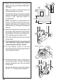
1
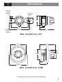
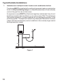
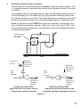
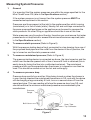
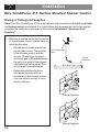
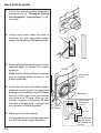
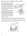
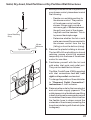
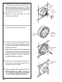
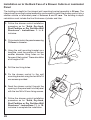
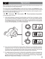
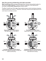
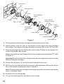
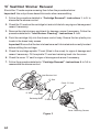
PRESSURE BALANCED
SHOWER CONTROL
Installation and
User Guide
THESE INSTRUCTIONS ARE TO BE LEFT WITH THE USER
Contents
Section
1 ....... Introduction
Page
................................................................... 3
2 ....... Important Safety Information ........................................... 4
3 ....... Pack Contents Checklist .................................................. 5
4 ....... Dimensions
................................................................... 7
5 ....... Specifications ................................................................... 8
6 ....... Installation Requirements ................................................ 9
7 ....... Installation
................................................................. 14
8 ....... Commissioning ............................................................... 29
9 ....... Operation ......................................................................... 33
10 ..... Fault Diagnosis ............................................................... 35
11 ..... Maintenance .................................................................... 41
12 ..... Spare Parts ...................................................................... 46
13 ..... Accessories .................................................................... 50
Guarantee, Customer Care Policy, and How to contact us .......
......................................................................................... Back cover
2
Section
1
Introduction
Thank you for purchasing a quality Mira product. To enjoy the full potential of your new
product, please take time to read this guide thoroughly, having done so, keep it handy for
future reference.
The Mira CombiForce 415 is a pressure balanced shower control which maintains a
constant outlet temperature irrespective of changes in inlet pressures as long as the
inlet water temperatures remain the same. It is not a thermostatic shower control and
does not sense supply temperature variations. Therefore, inlet water temperatures
especially the hot, should remain relatively constant.
The Mira CombiForce 415 can be installed with the following packages:
-
Fully modulating multipoint gas water heaters.
Fully modulating combination boilers.
Unvented mains pressure systems.
Mains pressurised, instantaneous hot water heated from thermal store, systems.
Pumped systems.
Showering temperature is adjusted by the shower control. The flow rate is determined by
the supply pressures available at the inlets, and the output rating of the heater appliance.
Shower controls covered by this guide:
Mira CombiForce 415
Surface mounted pressure balanced shower control for connection to exposed pipework,
for high pressure applications (1.0 – 5.0 bar). Available in white/chrome, white/light
golden or all chrome finish.
Mira CombiForce 415B
Built-in shower control for connection to concealed pipework, for high pressure
applications (1.0 – 5.0 bar). Available in white, white/chrome, white/light golden or all
chrome finish.
If you experience any difficulty with the installation or operation of your new
shower control, then please refer to Section 10, "Fault Diagnosis", before
contacting Kohler Mira Limited. Our telephone and fax numbers can be found on
the back cover of this guide.
3
Section
Important
Safety
Information
Important
Safety
Information
1Section
2
Warning!
1.
Products manufactured by us are safe and without risk provided they are
installed, used and maintained in good working order in accordance with our
instructions and recommendations.
Caution!
1.
Read all of these instructions.
2.
Retain this guide for later use.
3.
Pass on this guide in the event of change of ownership of the installation site.
4.
Follow all warnings, cautions and instructions contained in this guide.
5.
The plumbing installation must comply with the requirements of UK Water
Regulations/Byelaws (Scotland), Building Regulations or any particular
regulations and practices, specified by the local water supplier. The
installation should be carried out by a plumber or contractor who is
registered or is a member of an association such as:
6.
4
-
Institute of Plumbing (IOP), throughout the UK.
-
National Association of Plumbing, Heating and Mechanical Services
Contractors (NAPH & MSC), England and Wales.
-
Scottish and Northern Ireland Plumbing Employers’ Federation
(SNIPEF), Scotland and Northern Ireland.
Anyone who may have difficulty understanding or operating the controls of any
shower should be attended whilst showering. Particular consideration should
be given to the young, the elderly, the infirm, or anyone inexperienced in the
correct operation of the controls.
Section
Pack Contents Checklist
3
✔ Tick the appropriate boxes to familiarise yourself with the part names and to confirm
❏
that the parts are included.
1. Mira CombiForce 415 Surface Mounted Shower Control
1 x CombiForce 415 Shower Control
2 x 1/2" BSP Inlet Connector Nipples
2 x Compression Nuts
2 x 13/4" Fixing Screws
❏
❏
❏
❏
2 x Fibre Gaskets
2 x Pipe Concealing Plates
❏
1 x Outlet Nipple ❏
2 x Wallplugs
❏
2 x Olives
❏
❏
1 x 2.5 mm A/F
Hexagon Wrench ❏
1 x ‘O’ Seal ❏
5
2. Mira CombiForce 415B Built-in Shower Control
1 x Wall Mounting Bracket
1 x CombiForce 415 Shower Control
with Building-in Shroud ❏
1 x Control
Knob Cap
❏
1 x Concealing Plate,
Circular Mounting Bracket
and Foam Seal ❏
❏
1 x Outlet Nipple
3 x Compression Nuts
❏
❏
2 x M4 x 16 mm Screws
2 x No. 8 x 11/4" Fixing Screws
2 x Wallplugs
3 x Olives
❏
1 x 2.5 mm A/F
Hexagon Wrench ❏
3. Documentation
1 x Installation and User Guide
1 x Customer Support Brochure
6
❏
❏
❏
❏
1 x ‘O’ Seal ❏
2 x M4 x 30 mm Screws
❏
❏
Section
Dimensions
4
Top Inlet
(Falling)
Supplies
Back Inlet
Supplies
Ø56
Ø92
35
153
Bottom Inlet
(Rising)
Supplies
188.5
135
Mira CombiForce 415
132 A/F
135
92 A/F
Ø76
35
57 to 74
Ø163
Mira CombiForce 415B
All dimensions are nominal and in millimetres
7
Section
5
SPECIFICATIONS
Specifications
Mira CombiForce 415 and 415B
Pressure Range
Minimum maintained pressure: 1 bar.
Maximum maintained pressure: 5 bar.
Maximum static pressure: 10 bar.
Note! For optimum performance, the initial supply pressures should be nominally
equal.
Temperatures
Hot and cold water supply temperatures MUST remain relatively constant.
Maximum hot water temperature: 85°C.
Ideally the hot water temperature should never exceed 65°C. A water temperature of
60°C is considered sufficient to meet all normal requirements and will minimize the
deposition of scale in hard water areas.
Connections
Inlet
15 mm Compression or 1/2'' BSP male (CombiForce 415).
15 mm Compression (CombiForce 415B).
Outlet
1
/2'' BSP male (CombiForce 415).
15 mm Compression or 1/2'' BSP male (CombiForce 415B).
8
Section
6
Installation Requirements
1. Layout and sizing of pipework must be such that when other services are used,
pressures at the shower control inlets do not fall below the recommended minimum
(1 bar). The pressure balancing performance is impaired below 1 bar. When fitted
with some heater appliances the minimum maintained pressure may be above 1
bar, refer to the section Commissioning: “Multipoint gas water heaters” or
“Combination boilers”.
2. The Mira CombiForce 415 is not suitable for installation as part of a gravity-fed
plumbing system (i.e. in conjunction with a hot water cylinder and cold water
storage cistern), unless used in conjunction with an inlet pump producing a
maintained pressure of at least 1 bar.
3. When used with a fully modulating multipoint or combination boiler above 5 bar
maintained pressure, a pressure reducing valve will be necessary. For information
on measuring system pressures refer to Installation Requirements: "Measuring
System Pressures". For further information on pressure reducing valves consult
your local plumbing stockist.
4. Supply pipes MUST be flushed to clear debris before connecting the shower
control.
5. Conveniently situated isolating valves MUST be fitted for servicing purposes.
6. If the shower control is to be used with a fully modulating multipoint water
heater, fully modulating combination boiler, thermal store or unvented system
an expansion vessel must be fitted to accommodate the expansion of water in
the domestic hot water supply (this may already be part of the system, check
the details on the boiler/heater or contact the boiler/heater manufacturer).
7. No form of outlet flow control should be fitted, only Mira recommended fittings
should be used in the outlet pipework.
Key to symbols appearing throughout this guide.
Float operated valve
Twin impeller inlet pump
Stop or servicing valve
Tempering valve
Shower control
Mini expansion vessel
Warning or overflow pipe
Non-return Valve
Drop tight pressure reducing
valve (PRV)
9
Typical Suitable Installations
1.
Instantaneous multipoint water heaters and combination boilers
The shower MUST be installed with a multipoint gas water heater or combination
boiler of a fully modulating design (i.e. where the water draw-off rate indirectly
controls the gas flow rate to the burner).
An expansion vessel MUST be fitted (and regularly maintained) if any form of
backflow prevention device is fitted, e.g. non-return valve, PRV. This will ensure
that excess expansion or pulse pressures do not damage the product or the
plumbing system. The expansion vessel may already be fitted within the boiler
(check with the manufacturer) and is in addition to the normally larger central
heating expansion vessel.
COLD
HOT
Figure 1
10
2.
Unvented mains pressure showers
The shower can be installed with an unvented, stored hot water cylinder. Only
a "competent person" as defined by the Building Regulations may fit this type
of system.
For packages with no cold water take off after the appliance reducing valve, it
will be necessary to fit an additional drop tight pressure reducing valve when
the mains pressure is over 5 bar. The drop tight pressure reducing valve must
be set at the same value as the unvented package pressure reducing valve.
Note! An expansion vessel MUST be fitted (and regularly maintained) if any
form of backflow prevention device is fitted, e.g. non-return valve, PRV. This
will ensure that excess expansion or pulse pressures do not damage the product
or the plumbing system.
Safety devices
not shown
for clarity
HOT
COLD
Expansion
Vessel
Reduced
pressure to
cold inlet of
shower
High
Inlet
Pressure
High
Inlet
Pressure
Reduced
pressure to
unvented
cylinder
Combined outlet PRV
with internal non-return valves
- Expansion vessel required.
Reduced
pressure to
cold inlet of
shower
Reduced
pressure to
unvented
cylinder
Cold takeoff after PRV
- Expansion pressure taken up by
unvented cylinder expansion vessel.
Figure 2
11
3.
Mains pressurised instantaneous hot water shower, heated from a
thermal store
Packages of this type, fitted with a tempering valve can be used.
A drop tight pressure reducing valve MUST be fitted if the supply pressures
exceed 5 bar maintained.
An expansion vessel MUST be fitted (and regularly maintained) if any form of
backflow prevention device is fitted, e.g. non-return valve, PRV. This will
ensure that excess expansion or pulse pressures do not damage the product
or the plumbing system. The expansion vessel may already be fitted externally
or internally within the thermal store (check with thermal store manufacturer).
COLD HOT
Figure 3
4.
Pumped showers (inlet pumps)
The shower can be installed with an inlet pump (twin impeller). The pump
MUST be located on the floor next to the hot water cylinder. The hot water
cylinder/vent pipes must be arranged as shown to achieve air separation.
90 °
30 to 60 °
Air Separation
Figure 4
12
Measuring System Pressures
1.
General
It is important that the system pressures are within the range specified for the
Mira CombiForce 415 (refer to the Specifications section).
If the system pressure is not known then the system pressure MUST be
measured as explained in this section.
Pressures are those present at the inlet to the appliance either whilst running
(maintained) or in the off state (static). Nearby hot and cold taps connected to
the same proposed feed pipes as the appliance can be used to measure the
static pressure. No other fitting or appliance should be in use at this time.
Water pressures vary throughout the day, therefore you must ensure that water
pressures do not drop below or exceed the minimum/maximum required (refer
to the Specifications section).
2.
To measure static pressure (Refer to Figure 5)
With the pressure testing device firmly connected to a tap drawing from one of
the proposed feed pipes and the outlet from the device in the off position, the
tap is turned on and the static pressure noted.
3.
To measure maintained pressure (Refer to Figure 5)
The pressure testing device is connected as above, the taps turned on and the
outlet from the device opened until a flow of around 5 l/min is obtained (this is
easily done by timing the flow into a calibrated container). The maintained
pressure which can be expected when the shower is in operation can then be
read. This should be carried out on the hot and cold supply.
4.
To measure pressure drop
Pressure drop results from another fitting being turned on when the shower is
in use. Having checked the maintained pressure as in 3.3. and with the device
still discharging at approximately 5 l/min, turn on a second draw-off from the
same feed pipe. This new reading will show the pressure drop from 3.3. and
should be above the minimum maintained pressure recommended by the
manufacturer.
Pressure
Gauge
Ball Valve
Hose Type
Tap Connector
Pressure Testing Device
Figure 5
13
Section
7
Installation
Mira CombiForce 415 Surface Mounted Shower Control
Rising or Falling Inlet Supplies
Note! The Mira CombiForce 415 is supplied with inlet connections hot left, cold right
and bottom outlet as standard. For installations with reversed hot and cold supplies
complete the installation and refer to the section Installation: "Reversed Inlet
Supplies".
1. Before you decide on the final position
of your shower control, please bear in
mind the following:
- Decide on a suitable position for
the shower control. The position
of the shower control and the
shower fittings must provide a
minimum gap of 25 mm between
the spill-over level of the shower
tray/bath and the handset. This
is to prevent backsiphonage.
Hose Retaining
Ring
25 mm
Minimum
Spill-over Level
- Determine whether the hot or
cold water services will be
connected to the shower control
from the bottom (rising) or from
the top (falling).
Falling Supplies
Rising Supplies
14
2. Remove the backplate by releasing,
anticlockwise, the two recessed grub
screws which retain the backplate
against the brass shower control body,
using the 2.5 mm A/F hexagon wrench
(supplied).
Backplate
Grub
Screws
3. Mark the final position of the shower
control on the finished wall surface
using the backplate as a template.
Mark the position of the two holes on the
backplate. Ensure the holes are
vertically aligned.
WARNING! Ensure there are no buried
cables or pipes in the wall before drilling.
4. Drill the two marked fixing holes and fit
the wallplugs provided. Secure the
backplate to the wall with the two No. 8
x 13/4" fixing screws.
Note! Screws with larger heads will foul
the shower control body.
5. Thoroughly flush the incoming hot
and cold water supplies before
connecting the shower control.
'V' Groove
'O' Seal
6. Release, anticlockwise, the two grub
screws that retain the inlet elbows,
using the 2.5 mm A/F hexagon wrench
(supplied). Ensure that the ‘O’ seal is
correctly located on the smaller
diameter shoulder of the brass inlet
connector, and not in the ‘V’ groove.
Inlet
Grub
Elbow
Screw
15
Backplate
7. Fit the shower control body onto the
backplate and secure by tightening,
clockwise, the two recessed grub
screws, using the 2.5 mm A/F hexagon
wrench (supplied).
Grub Screws
Shower Control Body
8. Refit the elbows in the required position,
i.e. rising or falling supplies. Ensure the
grub screws locate into the 'V' groove
and tighten the grub screws.
Rising Supplies
Falling Supplies
9. Assemble the components of the inlet
connector compression fittings in the
following sequence for each inlet:9.1. Place the fibre gasket against
the shoulder of the 1/2" BSP
inlet connector nipple.
9.2. Screw, clockwise, the 1/2"
BSP connector nipple into
the elbow ensuring that the
compression taper faces
uppermost, using a 12 mm A/F
hexagon wrench (not supplied).
16
Connector
Nipple
Fibre
Gasket
15 mm Compression
Fibre Gasket
1
/2" Male BSP
Compression
Nut
Olive
9.3. Slide, in turn, the compression
nut, then the olive, over the hot
and cold inlet pipework. If
necessary, sparingly, smear
‘liquid jointing’ on the pipe end
and the outside of the olive.
9.4. Insert the hot and cold inlet
pipework into the opening of the
1 2
/ " BSP inlet connector nipple
then slide the olive and
compression nut into place.
9.5. Finally, carefully tighten,
clockwise, the compression nut.
If necessary use a cloth to
protect the plated surfaces.
10. Fit the ‘O’ seal to the tapered end of the
outlet nipple and screw it into the shower
control outlet using a 12 mm A/F
hexagon wrench (not supplied). This will
leave the flat face for connection to the
shower hose.
11. This completes the installation of the
Mira CombiForce 415 for “Rising or
Falling Inlet Supplies”.
'O' Seal
17
Back Inlet Supplies
1. Follow the shower control installation
procedure as for “Rising or Falling
Inlet Supplies”: instructions 1. to 4.
inclusive.
2. Using a spirit level, mark the route of
incoming hot and cold water supply
pipes at a distance of 153 mm centres.
3. Remove the plaster and brickwork to the
required depth to conceal the supply
pipework.
153 mm
Note! Depth must be sufficient to prevent
pipe concealing plates fouling on the
plumbing elbows.
4. Install the hot and cold water supply
pipework ensuring that the pipe ends
emerge from the wall surface at 153 mm
centres, and project from the finished
wall surface by 13 mm. Allow for two
circular recesses measuring 32 mm
diameter x 10 mm depth, to accept the
two pipework concealing plates.
Concealing
Plate
Backplate
13 mm from
finished wall
surface
Circular
Recess
32 mm
5. Make good the wall surface.
Fit the pipework concealing plates over
hot and cold water supply pipework.
18
Elbow
10 mm minimum
between elbow
and finished wall
surface.
1 2
"
/
Male
BSP
15 mm
Compression
Connector Nipple
Fibre
Gasket
6. Fit the gaskets to the 1/2" BSP connector
nipples and screw in the nipples with the
tapered ends outermost to accept the
compression fittings. Tighten the 1/2"
BSP connector nipples fully with a
12 mm A/F hexagon wrench (not
supplied).
7. Thoroughly flush the incoming hot
and cold water supply pipes before
connecting the shower control. Failure
to do so may result in product
malfunction.
Fibre
Gasket
8. Slip the compression nuts and olives
over the supply pipes.
9. Locate the shower control body onto the
backplate and inlet supply pipework,
then secure by tightening, clockwise,
the two recessed grub screws, using the
2.5 mm A/F hexagon wrench (supplied).
Tighten the compression nuts, using if
necessary, a cloth to protect the plated
surfaces.
Turn on the water supplies and check
for any leaks!
10. Fit the ‘O’ seal to the tapered end of the
outlet nipple and screw it into the shower
control outlet using a 12 mm A/F hexagon
wrench (not supplied). This will leave the
flat face for connection to the shower
hose.
'O' Seal
11. This completes the installation of the
Mira CombiForce 415 for “Back Inlet
Supplies”.
Connector Nipple
'O' Seal
19
Mira CombiForce 415B Built-in Shower Control
The built-in shower control incorporates an
integral wall mounting bracket assembly
which can be used to install the shower into
a solid, dry-lined, stud partition or dry
partition wall structure, shower cubicle or
laminated panel. Installers may wish to
consider other options such as fabricating
rear supports using wooden noggins,
however, these methods of fixing are beyond
the scope of this guide.
The building-in depth for the integral wall
mounting bracket assembly is 58 mm. The
building-in depth for the shower control (to
the finished wall surface) is between 64 and
81 mm. The building-in depth calculation
must include the final thickness of plaster
and tiles. This dimension determines how
much of the control knob will be visible
through the concealing plate when the
installation is completed.
230
134
Wall
Mounting
Bracket
53
43
110
146
214
92 A/F
12
38
Backplate
67
Ø101
A building-in shroud is supplied, which protects the shower control during plastering
and provides a reference for the building-in depth when chasing out the wall surface.
The built-in shower control has 1/2" BSP male inlets and is supplied with 15 mm
compression fittings. The outlet has a 1/2" BSP tapping and supplied with a nipple
terminating in a 1/2" BSP male or 15 mm compression fitting.
Building-in
Shroud
Raised
Portion
Hot
Inlet
Port
Outlet Port
20
Shower
Control
Solid, Dry-lined, Stud Partition or Dry Partition Wall Structures
1. Before you decide on the final position of
your shower control, please bear in mind
the following :
- Decide on a suitable position for
the shower control. The position
of the shower control and the
shower fittings must provide a
minimum gap of 25 mm between
the spill-over level of the shower
tray/bath and the handset. This is
to prevent backsiphonage.
Hose Retaining
Ring
25 mm
Minimum
Spill-over Level
- Determine whether the hot or cold
water services will be connected to
the shower control from the top
(falling) or from the bottom (rising).
2. Remove the plastic building-in shroud.
The two M5 x 50 mm building-in shroud
retaining screws should be screwed
temporarily into the base of the shower
control for use later.
3. Familiarise yourself with the hot and
cold water inlet ports and outlet port.
They can be identified as follows:
The Mira CombiForce 415B is supplied
with inlet connections hot left, cold
right and top outlet as standard.
To change the position of the outlet refer
to “Reversed Outlet Connection”:
instructions 1. to 8. inclusive.
4. Determine the route for the incoming hot
and cold water supply pipework. The
outlet pipework to a flexible shower fitting
is best positioned to emerge above and
to one side of the shower control to allow
the flexible hose to drape around the
underside of the shower preventing the
hose from interfering with the knob (refer
to diagram).
21
5. Mark the wall surface for an opening
measuring approximately 245 mm x
125 mm.
Mark the route of the incoming and
outgoing pipework services.
Using the building-in shroud as a guide
remove the plaster and brickwork/drylining to the required depth of
concealment.
Note! The depth of concealment must
be such that the final wall surface (e.g.
plaster and tiles etc.) finishes on the
raised portion of the plastic building-in
shroud.
125 mm
245 mm
6. Mark the final position on the wall of the
two larger outer diameter fixing holes in
the flanges of the wall mounting bracket.
This bracket must be fixed at 45°.
7. Drill and suitably plug the two marked
fixing holes.
8. Thoroughly flush the incoming hot
and cold water supply pipes before
connecting the shower control.
9. Fix the shower control to the wall
mounting bracket using the two M4 x 16
mm screws provided.
10. Install the shower control aligning the
two flange holes of the wall mounting
bracket assembly with the pre-drilled
fixing holes.
Secure the shower control with the two
No. 8 x 11/4" fixing screws supplied.
22
Shower Control
Wall Mounting
Bracket
11. Connect the incoming hot and cold water
supply pipes :
11.1 Slide the compression nut, then
the olive, over the pipe end. If
necessary, sparingly smear
liquid jointing on the pipe end
and the outside of the olive.
11.2 Insert the pipe end into the
opening of the inlet connector
then slide the olive and
compression nut into place.
11.3 Finally, carefully tighten,
clockwise, the compression
nuts.
Outlet
Nipple
'O' Seal
12. Connect the outlet pipe :
12.1 Place the ‘O’ seal on to the
nipple, as shown. Locate the
hexagon towards the shower
control outlet port. Screw the
nipple, clockwise, into the outlet
port using a 12 mm A/F
hexagon wrench (not supplied).
12.2 Slide the compression nut, then
the olive, over the pipe end. If
necessary, sparingly, smear
liquid jointing on the pipe end.
12.3 Insert pipe end into the opening
of the outlet nipple then slide
the olive and compression nut
into place.
12.4 Finally, carefully tighten,
clockwise, the components.
Turn on the water supplies and check
the pipework for any leaks!
13. Refit the plastic building-in shroud over
the shower control and secure with the
two M5 x 50 mm shroud retaining screws,
removed in instruction 2.
23
14. Plaster and tile up to the tapered sides
of the plastic building-in shroud and,
when set remove the shroud. The two
M5 shroud retaining screws should be
screwed temporarily into the base of the
shower control for use later.
Control
Knob
Control
Knob Cap
15. Push the control knob cap on to the
shower control knob.
16. Fit the foam seal over the reverse side
of the circular mounting bracket.
17. Fix the circular mounting bracket to the
shower control body using the two M5 x
50 mm screws used to retain the plastic
building-in shroud.
Note! The bracket has been designed
with semicircular knock outs which may
need to be relieved to accommodate the
supply pipework under minimum
building-in depth conditions.
18. Push the concealing plate firmly over
the circular mounting bracket until it
locates on the four clips.
19. This completes the installation of the
Mira CombiForce 415B for installation
into “Solid, Dry-lined, Stud Partition
or Dry Partition Wall Structures”.
24
Foam
Circular
Mounting
Seal
Bracket
M5 x 50 mm
Screw
Concealing
Plate
Shower Cubicle or Laminated Panel
The built-in shower control incorporates an integral wall mounting bracket assembly
which can be used to install the shower into the front or back face of a shower cubicle
or laminated panel.
Installation on to the Front Face of a Shower Cubicle or Laminated
Panel
Depending on the structure of the shower cubicle or laminated panel it may be possible
to conceal the flanges of the integral wall mounting bracket assembly into the front face
of the wall surface then cover over the fixings with plaster and tiles. The building-in depth
for the integral wall mounting bracket assembly is 58 mm. The thickness of plaster and
tiles which conceal the integral wall mounting bracket assembly flanges must be between
6 and 23 mm.
Wall
Mounting
Bracket
230
134
53
43
110
146
214
1. Follow the shower control installation
procedure as for “Solid, Dry-lined,
Stud partition or Dry Partition Wall
Structures”: instructions 1. to 4.
inclusive.
12
38
92 A/F
2. Cut a circular hole in the panel measuring
145 mm in diameter.
Backplate
67
Ø101
3. Follow the shower control installation
procedure as for “Solid, Dry-lined,
Stud Partition or Dry Partition Wall
Structures”: instructions 6. to 18.
inclusive to complete the installation.
25
Installation on to the Back Face of a Shower Cubicle or Laminated
Panel
The building-in depth for the integral wall mounting bracket assembly is 58 mm. The
integral wall mounting bracket assembly can be used to install the shower control into a
shower cubicle or laminated panel of between 4 and 21 mm. The building-in depth
calculation must include the final thickness of plaster and tiles.
1. Follow the shower control installation
procedure as for “Solid, Dry-lined,
Stud Partition or Dry Partition Wall
Structures”: instructions 1. to 4.
inclusive.
2. Cut a circular hole in the panel measuring
124 mm in diameter.
3. Using the wall mounting bracket as a
template, mark the position of the two
smaller diameter fixing holes on the
flanges of the bracket. These should be
at an angle of 45°.
4. Drill the two fixing holes.
5. Fix the shower control to the wall
mounting bracket using the two M4 x 16
mm screws provided.
6. Feed the shower control through the
opening in the panel and fix to the panel
with the two M4 x 30 mm fixing screws.
7. Follow the shower control installation
procedure as for “Solid, Dry-lined,
Stud Partition or Dry Partition Wall
Structures”: instructions 11. to 18.
inclusive to complete the installation.
26
Reversed Outlet Connection
Mira CombiForce 415 shower controls are supplied with inlet connections hot left, cold
right and bottom outlet. The Mira CombiForce 415B is supplied with inlet connections
hot left, cold right and top outlet as standard.
To reverse the outlet position:
1. Rotate the shower control body through 180o and install the shower control.
2. Prise off the concealing cap, unscrew the control knob retaining screw and remove
the temperature override stop and control knob.
3. Remove the D-shaped hub fitted to the spindle. Rotate the spindle one full turn (360o)
and refit the hub.
4. Remove the adjustable temperature stop and turn over. Make sure that the Max oC
with the indentations side is uppermost. Adjust the maximum temperature stop
(refer to Commissioning).
5. Refit the control knob assembly (with the override button at the bottom) and turn the
knob fully clockwise to the shut off position.
6. This completes the procedure for “Reversed Outlet Connection”.
Adjustable
Temperature Stop
Hub
Cover Shroud
Cover Shroud
Retaining Screws
Control Knob
Spindle
Plastic
Override
Stop
Skid Washer
The hub is 'D' shaped. This
ensures the hub is fitted in the
correct position.
Control Knob
Retaining Screw
Concealing
Cap
27
Reversed Inlet Supplies
Mira CombiForce 415 shower controls are supplied with inlet connections hot left, cold
right and bottom outlet. The Mira CombiForce 415B is supplied with inlet connections
hot left, cold right and top outlet as standard.
Both shower controls are fitted with a single sequential control knob.
The shower control is turned off by turning the control knob fully clockwise. The correct
sequence of operation is anticlockwise movement of the control knob followed by: Cold
Warm Hot water. If the sequence is: Hot Warm Cold water, then the hot and
cold water supplies have been reversed.
To correct reversed hot and cold inlet supplies proceed as follows:
1. Prise off the concealing cap, remove the control knob retaining screw/plastic
temperature override stop and the control knob.
2. Remove the hub. Turn the spindle one full turn (360o). Refit the hub.
3. Refit the control knob, (with the override button at the bottom), the control knob
retaining screw/plastic override stop and the concealing cap.
4. Check the maximum temperature. Adjust if necessary (refer to Commissioning).
5. Turn the knob fully clockwise to the shut off position.
6. This completes the procedure for "Reversed Inlet Supplies".
Hub
Skid Washer
Control Knob
Plastic Override
Stop
Control Knob
Retaining Screw
Concealing Cap
28
Section
8
Commissioning
All heater appliances must have a fully modulating heat output for the domestic
hot water, to provide a constant temperature of hot water to the Mira CombiForce 415
shower control.
Multipoint Gas Water Heaters
These notes are based on a heater with an effective output power of 23.5 kW. Heaters with
higher or lower effective output powers will proportionally affect the following information.
The Mira CombiForce 415 range does not compensate for water temperature
changes.
1. Use the heater appliance on a “high” or “winter” setting only.
2. A minimum maintained water supply pressure of 1.5 bar is required to the water
heater. This allows for a 0.5 bar pressure loss in the heater and ensures the
maintained inlet pressure at the shower is above 1 bar.
3. The maintained water supply pressure should not exceed 5 bar. A pressure reducing
valve will be needed for pressures over 5 bar to improve the system operation. It
should be installed to reduce both the cold feed pressure to the heater and the cold
feed pressure to the Mira CombiForce 415 to approximately 3.5 bar.
Additional benefits may be obtained by fitting the pressure reducing valve after the
premises internal stop valve, drain valve and if fitted, outside tap. The valve should
be correctly sized for the duty.
4. If the minimum modulating output of the heater appliance exceeds 14 kW with a
reducing hot flow rate, then the maintained minimum supply pressure will need to
be increased. This is to keep the flow rate through the heater sufficiently high in order
to ensure that the gas flame stays ignited. An extinguished flame will produce a cold
shower after a short period of time.
Combination Boilers
1. This information is based on a heater appliance fitted with an internal flow regulator
rated at 10 l/min hot water.
2. Use the heater appliance on a “high” or “winter” setting only.
3. Should it not be possible to get a hot enough shower it may be necessary to fit a
9 l/min flow regulator (available from Kohler Mira Customer Services) between the
shower control and hose to further reduce the flow. The “top hat” regulator should
fit into the hose recess such that the black ‘O’ seal is visible before attaching the
hose to the shower control.
4. A minimum maintained water supply pressure of 1.5 bar is required. This allows for
a 0.5 bar pressure loss in the heater.
29
5. The maintained water supply pressure should not exceed 5 bar. A pressure reducing
valve will be needed for pressures over 5 bar to improve the system operation. It
should be installed to reduce both the cold feed pressure to the heater appliance
and the cold feed pressure to the Mira CombiForce 415 to approximately 3.5 bar.
Additional benefits may be obtained by fitting the water pressure reducing valve
after the premises internal stop valve, drain valve and if fitted, outside tap. The
valve should be correctly sized for the duty.
6. The minimum maintained water supply pressure will need to be raised if the
minimum heater output power is greater than 7.5 kW on a reducing flow with a hot
temperature of 62.5°C.
Adjustable Maximum Temperature Setting
Mira CombiForce 415 shower controls are fully performance tested. The adjustable
maximum temperature (maximum angular movement prior to override) has been preset
under ideal installation conditions at the factory. Site conditions and personal preference
may dictate that the maximum temperature needs to be reset.
To reset the adjustable maximum temperature stop ensure that an adequate supply of hot
water is available in excess of that required from the shower control. Turn the control knob
fully anticlockwise. Check the temperature at the discharge point (allow hot water to reach
the shower). If incorrect, adjust the temperature as follows:
1. Turn the control knob anticlockwise until the desired maximum temperature is
achieved. It may be necessary to press the override button and continue to rotate
anticlockwise, past the preset maximum temperature setting. Note the final
position of the button, e.g. 11 O ’clock.
2. Turn the control knob fully off.
3. Remove the concealing cap.
4. Remove the control knob retaining screw/plastic temperature override stop and pull
off the control knob.
5. Locate the adjustable temperature stop (identified by a part number and a “MAX °C”
symbol or a “MAX °C” symbol and component indentations).
Note! Ensure that the original face identified, is uppermost after adjustment.
6. With reference to the diagrams, carefully remove the adjustable temperature stop.
Reposition the stop so that the “MAX °C” symbol is aligned with the noted button
position, e.g. 11 O’ clock.
7. To check the desired maximum temperature setting has been correctly set, refit the
hub and control knob, turn fully anticlockwise and check the temperature of the
water at the outlet. If still incorrect:
To increase the temperature, reposition the stop one serration anticlockwise.
30
To decrease the temperature, reposition the stop one serration clockwise.
Repeat the check as necessary.
Control Knob
Control Knob
Retaining Screw
Temperature
Override Button
Adjustable
Temperature
Stop
Adjustable
Temperature
Stop
Plastic
Override
Stop
Concealing
Cap
Indentations
8. Refit the control knob (with the override button at the bottom), control knob retaining
screw/plastic override stop and concealing cap.Please ensure the plastic override
stop is correctly seated.
Note! Do not overtighten the control knob retaining screw. Internal components may
be damaged if the screw is overtightened.
9. This completes the procedure for Commissioning: "Adjustable Maximum
Temperature Setting”.
31
Temperature Override Button Disable
The Mira CombiForce 415 incorporates a safety feature which prevents the
temperature override button from being depressed, enabling the user to access a
higher shower temperature. The shower control is despatched from the factory with
the button in the “enabled” position.
The following sequence will allow the installer to “disable” the temperature override
button if required.
1. Ensure the shower control is turned off.
Remove the concealing cap.
2. Locate the plastic temperature override stop.
3. Pull out the temperature override stop and reposition it in the slot adjacent to the
red temperature override button.
4. Reversing the above procedure will “enable” the temperature override button
movement.
Temperature
Override Button
Temperature
Override Stop
Temperature Override
Button Enabled
32
Temperature Override
Button Disabled
Section
Operation
9
Mira CombiForce 415 shower has a single control knob which turns the shower control
on/off and adjusts the water temperature.
Turn the control knob anticlockwise to start the flow of water and clockwise to stop.
To increase the showering temperature turn the control anticlockwise and clockwise to
decrease the water temperature. Starting from the off position and turning the control
knob anticlockwise the sequence is :
Off
➡
Cold water
➡
Warm water
➡
Preset maximum temperature
A fuller description follows :
1. Initial anticlockwise movement turns the water on at full flow of cold water, further
anticlockwise movement increases the temperature. The flow rate is determined by
the supply pressures at the shower control inlets, or by the effective output power
of the heater appliance. Flow rates for gas heater appliances can vary typically
between 8 l/min (winter) and 15 l/min (summer).
=
+
=
+
=
+
MAX. ºC
2. The control knob is fitted with a button which allows you to override the maximum
temperature stop. This can be used when the initial hot water supply temperature
has fallen due to increased demand or when a hotter shower is required. The override
mechanism self cancels when the knob is returned to the off position.
3. For safety reasons this product is fitted with a adjustable maximum temperature
stop. This setting must be checked and adjusted as necessary to suit both site
conditions and user’s comfort. Refer to the section Commissioning: “Adjustable
Maximum Temperature Setting” for further details.
33
How the pressure balancing principle operates
Mira CombiForce 415 pressure balanced shower controls automatically adjust for
variations in inlet pressures. This will maintain a constant outlet temperature
provided the inlet water temperatures remain stable.
The Mira CombiForce 415 is not a thermostatic shower control and does not sense
supply temperature variations. Therefore, inlet water temperatures especially the hot,
must remain relatively constant.
Hot
Cold
Equal Hot and Cold Pressure
The diaphragm is in the centre.
Hot
Cold
Low Hot and High Cold Pressure
Diaphragm deflects towards hot inlet and
restricts cold entry.
34
Hot
Cold
Water
Loss
Cold Water Pressure Loss
Diaphragm moves to close hot inlet.
Hot
Cold
High Hot and Low Cold Pressure
Diaphragm deflects towards cold inlet
and restricts hot entry.
Section
10
Fault Diagnosis
Customer Fault Diagnosis
The trouble shooting information tabled below gives details on what you can do as a
user should you encounter difficulties whilst operating the shower.
Note! Should these remedies prove to be unsuccessful in solving your problem, contact
your installer for further advice.
Key for applicability column
A - Instantaneous gas heated showers.
B - Unvented mains pressure showers.
C - Mains pressurised, instantaneous hot water, heated from thermal store showers.
Malfunction
Shower
insufficiently hot.
Cause
(a) Maximum
temperature
incorrectly set.
Reset adjustable
maximum
temperature.
(b) Heater not set on
maximum hot.
Consult heater
instructions or contact a
CORGI registered
installer.
Fit 9 l/min flow regulator
between shower control
and hose.
(c) Flow rate still too
high.
Wide temperature
fluctuations from
shower when no
other draw-off is
being made.
Remedy
(a) Insufficient flow
rate causing the
heater to cycle on
and off.
(b) Insufficient water
pressure causing
the heater to
cycle on and off.
(c) Heater not fully
modulating.
A B C
Check and clean inlet
strainers.
Contact your local water
supplier or a CORGI
registered installer.
Contact a CORGI
registered installer. See
Installation
Requirements.
(d) See also
“Shower
insufficiently
hot”.
35
Malfunction
Shower pattern
collapses when
another hot tap is
turned on.
Cause
Remedy
(a) The heater is not
capable of supplying
several outlets at
the same time.
(b) Inlet strainer
blocked.
Reduce the
simultaneous demand.
(a) Property water
supply pipe
partially blocked or
undersized.
(b) Property stop or
servicing valve not
fully open.
(c) Insufficient mains
cold water pressure.
Contact the local water
supplier or your installer.
Open valve.
(d) Inlet strainer
blocked.
Check and clean inlet
strainers.
Shower control
operating sequence
is “off, hot, cool”.
Hot and cold water
supplies have been
connected in reverse.
Refer to the section
Installation:“Reversed
Inlet Supplies”.
Shower insufficiently
hot without pressing
red button and
rotating further.
Adjustable maximum
temperature incorrectly
set.
Refer to the section
Commissioning:
“Adjustable Maximum
Temperature Setting”.
Shower control
"drums" whilst in
use.
(a) Inlet strainer
blocked creating
an excessive
imbalance in inlet
pressures.
Check and clean inlet
strainers.
(b) Supply pressure in
excess of 5 bar
maintained.
Contact your installer.
Shower pattern
collapses when
another cold tap is
turned on.
Shower control
"thumps" when
another tap is
suddenly turned off.
36
Check and clean inlet
strainers
Contact the local water
supplier or your installer.
Inlet check valve faulty. (a) Remove cartridge
and if possible
clear check valve
obstruction.
(b) Renew cartridge.
A B C
Malfunction
Cause
Remedy
Shower force too
strong.
High pressure supplies.
Fit 9 l/m flow regulator.
No hot water
available
(a) Heater appliance
not igniting due to
insufficient mains
pressure.
Contact the local water
supplier or a CORGI
registered installer.
(b) Heater appliance
not igniting due to
appliance fault.
Contact a CORGI
registered installer.
(c) Product hot or cold
isolating valve not
fully open.
Open valve.
(d) Hot water run out.
Wait until reheated.
(e) Inlet strainer
blocked.
Check and clean inlet
strainers.
(a) Insufficient flow
rate.
Refer to “Wide
temperature
fluctuations”.
(b) Hot water supply
temperature
dropped.
Wait for hot water to
reheat.
(a) Pipework not
flushed before
connecting shower
control. (Internal ‘O’
seals damaged).
Renew cartridge. Refer
to the section
Maintenance:
“Cartridge Renewal”.
(b) Cartridge or inlet
strainer ‘O’ seals
damaged.
Renew ‘O’ seals with
Service Pack.
(a) Supply stop valve
turned down or off.
(b) Inlet Strainers
blocked.
(c) Hose or handset
blocked.
Open valve.
Shower starts warm
and then runs cool.
Shower control
cannot be shut off.
No flow or low flow
from shower head.
(d) Spray plate
blocked.
A B C
Clean or renew.
Clear blockage. If
necessary renew hose
or handset.
Remove and clean.
37
Installer Fault Diagnosis: refer to appliance diagram and customer fault
diagnosis
Read the section “Important Safety Information” first.
Providing the shower has been correctly installed and is operated in accordance with
the instructions contained in this guide, difficulties should not arise. If any
maintenance is required then it must be carried out by a competent tradesperson for
whom the fault diagnosis chart and maintenance instructions are provided. To work on
gas heater appliances an installer MUST be CORGI registered. Before replacing any
parts ensure that the underlying cause of the malfunction has been resolved.
Key for applicability column
A - Instantaneous gas heated showers.
B - Unvented mains pressure showers.
C - Mains pressurised, instantaneous hot water, heated from thermal store showers.
Malfunction
Shower
insufficiently hot.
Wide temperature
fluctuations from
shower when no
other draw-off is
being made.
Cause
(a) Maximum
temperature
incorrectly set.
Reset adjustable
maximum
temperature.
(b) Heater not set on
maximum hot.
Consult heater
instructions for further
instructions.
(c) Flow rate still too
high.
Fit 9 l/min flow regulator
between shower control
and hose.
(a) Insufficient flow
rate causing the
heater to cycle on
and off.
(b) Insufficient water
pressure causing
the heater to
cycle on and off.
Check and clean inlet
strainers.
(c) Heater not fully
modulating.
(d) See also
“Shower
insufficiently
hot”.
38
Remedy
Increase supply pipe
size to premises.
Refer to Installation
Requirements.
A B C
Malfunction
Shower pattern
collapses when
another hot tap is
turned on.
Shower pattern
collapses when
another cold tap is
turned on.
Cause
Remedy
(a) The heater is not
capable of supplying
several outlets at
the same time.
(b) Inlet strainer
blocked.
Reduce the
simultaneous demand.
(a) Property water
supply pipe
partially blocked or
undersized.
(b) Property stop or
servicing valve not
fully open.
(c) Insufficient mains
cold water pressure.
Contact the local water
supplier or increase
supply pipe size to
premises.
Open valve.
Check and clean inlet
strainers
(d) Inlet strainer
blocked.
Contact the local water
supplier or increase
supply pipe size to
premises.
Check and clean inlet
strainers.
Shower control
operating sequence
is “off, hot, cool”.
Hot and cold water
supplies have been
connected in reverse.
Refer to the section
Installation:“Reversed
Inlet Supplies”.
Shower insufficiently
hot without pressing
red button and
rotating further.
Adjustable maximum
temperature incorrectly
set.
Refer to the section
Commissioning:
“Adjustable Maximum
Temperature Setting”.
Shower control
"drums" whilst in
use.
(a) Inlet strainer
blocked creating
an excessive
imbalance in inlet
pressures.
(b) Supply pressure in
excess of 5 bar
maintained.
Check and clean inlet
strainers.
Shower control
"thumps" when
another tap is
suddenly turned off.
A B C
Fit pressure reducing
valve. Refer to
Installation
Requirements.
Inlet check valve faulty. (a) Remove cartridge
and if possible
clear check valve
obstruction.
(b) Renew cartridge.
39
Malfunction
Cause
Remedy
Shower force too
strong.
High pressure supplies.
Fit 9 l/m flow regulator.
No hot water
available
(a) Heater appliance
not igniting due to
insufficient mains
pressure.
Contact the local water
supplier or increase
supply pipe size to
premises.
(b) Heater appliance
not igniting due to
appliance fault.
Refer to heater
appliance instructions.
(c) Product hot or cold
isolating valve not
fully open.
Open valve.
(d) Hot water run out.
Wait until reheated.
(e) Inlet strainer
blocked.
Check and clean inlet
strainers.
(a) Insufficient flow
rate.
Refer to “Wide
temperature
fluctuations”.
(b) Hot water supply
temperature
dropped.
Wait for hot water to
reheat.
(a) Pipework not
flushed before
connecting shower
control. (Internal ‘O’
seals damaged).
Renew cartridge. Refer
to the section
Maintenance:
“Cartridge Renewal”.
(b) Cartridge or inlet
strainer ‘O’ seals
damaged.
Renew ‘O’ seals with
Service Pack.
(a) Supply stop valve
turned down or off.
(b) Inlet Strainers
blocked.
(c) Hose or handset
blocked.
Open valve.
Shower starts warm
and then runs cool.
Shower control
cannot be shut off.
No flow or low flow
from shower head.
(d) Spray plate
blocked.
40
Clean or renew.
Clear blockage. If
necessary renew hose
or handset.
Remove and clean.
A B C
Section
11
Maintenance
Mira products are precision engineered to provide satisfactory performance provided
they are installed and operated in accordance with the recommendations contained in
this guide.
The shower control is designed for the minimum of maintenance in normal domestic
use. If a malfunction occurs then this will probably necessitate a complete cartridge
replacement.
Important! The cartridge contains no internally serviceable parts.
When installed in very hard water areas (above 200 p.p.m. temporary hardness) your
installer may advise the installation of a water treatment device to reduce the effects
of limescale formation in the heating appliance and spray plates.
Cleaning
Many household cleaners contain abrasives and chemical substances and should not
be used for cleaning plated or plastic fittings. These finishes should be cleaned using
a mild washing up detergent or soap solution, and then wiped dry using a soft cloth.
The light golden colour finish is softer than the chrome finish and its abrasive
resistance much less. When cleaning or using tools during maintenance extra care
must be taken.
Component Interchangeability
Some parts of the latest Mira CombiForce 415 are not interchangeable with earlier
models of the Mira range. Spare parts, where different, are available for earlier
models. Refer to the specific IO&M guide supplied with your shower or contact
customer services for further information (telephone and fax numbers can be found on
the back cover of this guide).
Cartridge Renewal
Should the cartridge require renewal then the following procedure should be followed:
Important! Use only silicone based lubricants when reassembling.
1. Turn off the water supplies and open the shower control to relieve the trapped water
pressure.
2. Prise off the concealing cap, remove the control knob retaining screw/plastic
override stop and the control knob.
3. Remove the two shroud retaining screws and the cover shroud. Note the position
of the adjustable temperature stop then remove. Remove the hub.
4. Undo the four cover retaining screws and remove the cover. (A quantity of water will
be discharged).
41
Plastic Pins
'O' Seal
Retaining Bush
'O' Seal
Cover Retaining
Screws
Cartridge
'O' Seal
Hub
Cover 'O' Seal
Cover Shroud
Retaining Screws
Skid
Washer Plastic
Override
Stop
Cover
Adjustable
Temperature
Stop
Cover Shroud
Control Knob
Retaining Screw
Figure 1
Concealing Cap
5. Pull the pressure balancing cartridge from the shower control body.
6. Identify which is the hot inlet of the shower control and fit the new cartridge
accordingly. The inlets on the new cartridge are marked “H” for Hot, “C” for Cold.
7. Push the cartridge fully into the shower control body. Ensure the two plastic pins
locate in the brass body recess.
Make sure that the arrow on the end face of the cartridge points to the letter "C" (refer
to Figure 2).
Important! Ensure that the two inlet seals are well-lubricated and correctly located
before refitting the cartridge.
8. Ensure that the cover “O” seal is correctly located on the cover.
9. Refit the cover, and secure with the four cover retaining screws. Make sure that the
flat on the spindle is lowermost (refer to Figure 2).
Note! There is a one-way cartridge location feature on the cover which ensures the
cover is correctly fitted.
10. Push the hub onto the spindle.
11. Turn on the water supplies, and check for any leaks.
42
Arrow
H
C
Flat On Spindle
End View Of Cartridge
Figure 2
12. Refit the adjustable temperature stop in its original position.
13. Temporarily fit the control knob (with the override button at the bottom). Rotate the
control knob anticlockwise until the desired temperature is achieved.
Note the final position of the override button, e.g. 11 O’ clock. Rotate the control
knob to the “off” position.
14. The maximum temperature will now require resetting following the procedure
“Adjustable Maximum Temperature Setting” in the section Commissioning.
43
‘O’ Seal/Inlet Strainer Renewal
Should the ‘O’ seals require renewing then follow the procedure below:
Important! Use only silicone based lubricants when reassembling.
1. Follow the procedure detailed in “Cartridge Renewal”: instructions 1. to 5. to
dismantle the shower control.
2. Check the ‘O’ seals on the cartridge hot and cold inlets for any signs of damage and
renew if necessary.
3. Remove the inlet strainers and check for damage, renew if necessary. Follow the
procedure detailed in “Inlet Strainer Cleaning”: instructions 2. to 4.
4. Push the cartridge fully into the shower control body. Ensure the two plastic pins
locate in the brass body recess.
Important! Ensure that the two inlet seals are well-lubricated and correctly located
before refitting the cartridge.
5. Check the cartridge spindle ‘O’ seal (fitted in the cover) for signs of damage and
renew if necessary. Fit the spindle ‘O’ seal and retaining bush into the cover.
6. Check the cover ‘O’ seal for signs of damage and renew if necessary.
7. Follow the procedure detailed in “Cartridge Renewal”: instructions 8. to 14. to
reassemble the shower control.
Inlet Strainer Unit
'O' Seal
Cover 'O' Seal
Cover
Plastic Pins
'O' Seal
Cartridge
Retaining Bush
'O' Seal
Cover Retaining Screws
Figure 3
44
Inlet Strainer Cleaning
Should the inlet strainer units require cleaning or renewal then follow the procedure
below:
Important! Use only silicone based lubricants when reassembling.
1. Follow the procedure detailed in “Cartridge Renewal”: instructions 1. to 5. to
dismantle the shower control.
2. Pull the inlet strainer units from the valve body.
3. Clean the complete strainer unit under running water. Check for damage and renew
the whole unit if necessary.
4. Refit the strainer units. The strainer units can only be fitted one way (refer to
Figure 4).
Important! Ensure the 'O' seals on the inlet strainers are well-lubricated before
refitting.
5. Follow the procedure detailed in “Cartridge Renewal”: instructions 7. to 14. to
reassemble the shower control.
Inlet Strainer Unit
Cover 'O' Seal
Cover
Plastic Pins
'O' Seal
Cartridge
Figure 4
Cover Retaining
Screws
45
Section
Spare Parts
12
CombiForce 415 Spare Parts List
012.12
Cover
242.55
Adjustable Temperature Stop
280.07
Inlet Compression Fitting - chrome
280.15
Inlet Compression Fitting - light golden
553.35
Outlet Nipple Assy - chrome
553.54
Outlet Nipple Assy - light golden
575.12
2.5mm Hexagon Wrench
617.18
CombiForce 415 Body (including strainers)
617.20
Shroud Pack CombiForce 415 - white
617.21
Shroud Pack CombiForce 415 - chrome
617.22
Control Knob Assembly CombiForce 415 - white
617.23
Control Knob Assembly CombiForce 415 - chrome
617.29
Shroud Pack CombiForce 415 - white/light golden
802.27
Inlet Elbow Assembly - chrome
802.33
Inlet Elbow Assembly - light golden
902.55
Cartridge Assembly
932.25
Hub Pack
936.22
CombiForce 415 Service Pack - components identified 'A'
46
CombiForce 415 Spare Parts Diagram
617.20
617.21
617.29
280.07
280.15
802.27
802.33
617.20
617.21
617.29
A
A
012.12
A
575.12
617.18
A
A
A
A
242.55
902.55
A
553.35
553.54
617.22
617.23
932.25
A
A
47
CombiForce 415B Spare Parts List
012.12
Cover
119.85
Wall Mounting Bracket
242.55
Adjustable Temperature Stop
410.53
Concealing Plate - white
410.54
Concealing Plate - chrome
410.55
Concealing Plate - light golden
555.67
Outlet Nipple
575.12
2.5mm Hexagon Wrench
617.19
CombiForce 415B Body (including strainers)
617.22
Control Knob Assembly - white
617.23
Control Knob Assembly - chrome
807.28
Backplate Assembly - components identified 'B'
902.55
Cartridge Assembly
932.04
Inlet Compression Fitting
932.25
Hub Pack
936.22
CombiForce 415 Service Pack - components identified 'A'
937.59
Screw Pack - components identified 'C'
48
CombiForce 415B Spare Parts Diagram
119.85
B
B
555.67
617.19
932.04
A
C
A
A
A
B
012.12
A
575.12
A
242.55
902.55
932.25
A
A
A
C
617.22
617.23
410.53
410.54
410.55
C
49
Section
13
Accessories
DCV-H: An outlet double check valve, requiring a minimum inlet supply pressure of
0.5 bar, which has been designed to prevent the backflow or backsiphonage of
potentially contaminated water, through shower controls which are fitted with a flexible
hose as part of the outlet shower fitting. Available as an optional accessory from your
Mira stockist.
DCV-H Outlet double check valve
9 litre/min Outlet Flow Regulator (Part No. 146.84 ): Designed to limit the flow
rate in high pressure installations. If the maximum obtainable water temperature at the
shower outlet is not sufficiently hot, fitting a flow regulator may increase the outlet
water temperature and may also reduce the shower force at the outlet (see
Commissioning). Available from Mira customer services.
9 litre/minute Flow Regulator
50
Appendix
Notes
51
Section
Customer Service
Guarantee of Quality
After Sales Service
Mira Showers guarantee products against any defect of
materials or workmanship for one year from the date of
purchase (2 years for Mira Select and 3 years for Mira Excel
ranges).
Our Customer Services Team is comprehensively trained
to provide every assistance you may need: help and
advice, spare parts or a service visit.
To validate the guarantee, please return your completed
registration card.
Within the guarantee period we will resolve defects, free of
charge, by repairing or replacing parts or modules as we may
choose.
We maintain an extensive stock of spares, and aim to have
functional parts available for ten years from the date of
final manufacture of the product.
Spares can be purchased from approved stockists or
merchants (locations on request) or direct from Customer
Services.
Spares direct will normally be despatched within two
working days. Payment can be made by Visa or Access
at the time of ordering. Should payment by cheque be
preferred a pro-forma invoice will be sent.
Note! In the interests of safety, spares requiring exposure
to mains voltages can only be sent to competent persons.
To be free of charge, service work must only be undertaken
by Mira Showers or our approved agents in Northern Ireland
and Republic of Ireland.
Service under this guarantee does not affect the expiry
date. The guarantee on any exchanged parts or product
ends when the normal product guarantee period expires.
Spare Parts
Not covered by this guarantee:
Service
Damage or defects arising from incorrect installation, improper
use or lack of maintenance, including build-up of limescale.
Our Service Force is available to provide a quality service at
a reasonable cost. You will have the assurance of a Mira
trained engineer/agent, genuine Mira spares – and a 12 month
guarantee on the repair.
Damage or defects if the product is taken apart, repaired or
modified by any person not authorised by Mira Showers or our
approved agents.
This guarantee is in addition to your statutory and other
legal rights.
To contact us:
Before using your shower
England, Scotland & Wales
Please take the time to read and understand the operating
and safety instructions detailed in this manual.
What to do if something goes wrong
If when you first use your shower it doesn’t function correctly,
first contact your installer to check that installation and
commissioning are satisfactory and in accordance with the
instructions in this manual. We are on-hand to offer you or your
installer any advice you may need.
Should this not resolve the difficulty, simply contact our
Customer Services who will give every assistance, and if
necessary arrange for our service engineer to visit.
If later the performance of your shower declines, consult this
manual to see whether simple home maintenance is required.
Please call our Customer Services to talk the difficulty
through, request service under guarantee if applicable, or
take advantage of our comprehensive After-Sales service.
As part of our quality and training programme calls
may be recorded or monitored
Mira Showers
Kohler Mira Ltd
Cromwell Road,
Cheltenham GL52 5EP.
P3740/3
Payment should be made directly to the Service Engineer/
Agent, using Visa, Access or a cheque supported by a
banker’s card.
Mira Showers Customer Services
Telephone:
01242 262888
8.30am to 5pm Working days (4.30pm Fri)
8.30 am to 12.30pm Saturday
E-mail: [email protected]
Fax:
01242 282595
By Post:
Cromwell Road
Cheltenham
Gloucester GL52 5EP
For Customers in Northern Ireland
Wm H Leech & Son Ltd
Telephone:
028 9044 9257 – Mon to Fri 9 am-5pm
Fax:
028 9044 9234 – 24 hours
Post:
Maryland Industrial Estate
Ballygowan Road
Moneyreagh, Co Down
BT23 6BL
For Customers in Republic of Ireland
Modern Plant Ltd
Telephone: Dublin 01 4591344 - Mon to Fri 9am to 5pm
Fax:
Dublin 01 4592329 – 24 hours
Post:
Otter House
Naas Road
Clondalkin
Dublin 22
Mira is a registered trade mark.
The company reserves the right to alter product
specifications without notice.
www.mirashowers.com
© Kohler Mira Limited, August 2003