1
DMDVB20 LBST
L-Band Satellite Modulator
With DVB-S2 Receiver
and ODU Driver
Installation and Operation Manual
TM138
Revision 1.0
Radyne Corporation • 3138 E. Elwood St. • Phoenix, AZ 85034 • (602) 437-9620 • Fax: (602) 437-4811 • www.radn.com
DMDVB20 LBST Satellite Modem
Warranty Policy
Warranty Policy
WP
Radyne Corp. (Seller) warrants the items manufactured and sold by Radyne Corp. to be free of defects in
material and workmanship for a period of two (2) years from date of shipment Radyne Corp.’s obligation
under its warranty is limited in accordance with the periods of time and all other conditions stated in all
provisions of this warranty.
This warranty applies only to defects in material and workmanship in products manufactured by Radyne
Corp. Radyne Corp. makes no warranty whatsoever concerning products or accessories not of its
manufacture. Repair, or at the option of Radyne Corp., replacement of the Radyne Corp. products or
defective parts therein shall be the sole and exclusive remedy for all valid warranty claims.
Warranty Period
The applicable warranty period shall commence on the date of shipment from a Radyne Corp. facility to the
original purchaser and extend for the stated period following the date of shipment. Upon beginning of the
applicable Radyne Corp. warranty period, all customers’ remedies shall be governed by the terms stated or
referenced in this warranty. In-warranty repaired or replacement products or parts are warranted only for the
remaining unexpired portion of the original warranty period applicable to the repaired or replaced products or
parts. Repair or replacement of products or parts under warranty does not extend the original warranty
period.
Warranty Coverage Limitations
The following are expressly not covered under warranty:
1.
Any loss, damage and/or malfunction relating in any way to shipping, storage, accident, abuse,
alteration, misuse, neglect, failure to use products under normal operating conditions, failure to use
products according to any operating instructions provided by Radyne Corp., lack of routine care
and maintenance as indicated in any operating maintenance instructions, or failure to use or take
any proper precautions under the circumstances.
2.
Products, items, parts, accessories, subassemblies, or components which are expendable in
normal use or are of limited life, such as but not limited to, bulbs, fuses, lamps, glassware, etc.
Radyne Corp. reserves the right to revise the foregoing list of what is covered under this warranty.
Warranty Replacement and Adjustment
Radyne Corp. will not make warranty adjustments for failures of products or parts, which occur after the
specified maximum adjustment period. Unless otherwise agreed, failure shall be deemed to have occurred
no more than seven (7) working days before the first date on which Radyne Corp. receives a notice of
failure. Under no circumstances shall any warranty exceed the period stated above unless expressly agreed
to in writing by Radyne Corp.
Liability Limitations
This warranty is expressly in lieu of and excludes all other express and implied warranties, Including but not
limited to warranties of merchantability and of fitness for particular purpose, use, or applications, and all
other obligations or liabilities on the part of Radyne Corp., unless such other warranties, obligations, or
liabilities are expressly agreed to in writing by Radyne Corp.
All obligations of Radyne Corp. under this warranty shall cease in the event its products or parts thereof
have been subjected to accident, abuse, alteration, misuse or neglect, or which have not been operated and
maintained in accordance with proper operating instructions.
TM138 – Rev. 1.0
iii
Warranty Policy
DMDVB20 LBST Satellite Modem
In no event shall Radyne Corp. be liable for Incidental, consequential, special or resulting loss or damage of
any kind howsoever caused. Radyne Corp.’s liability for damages shall not exceed the payment, if any,
received by Radyne Corp. for the unit or product or service furnished or to be furnished, as the case may be,
which is the subject of claim or dispute.
Statements made by any person, including representatives of Radyne Corp., which are inconsistent or in
conflict with the terms of this warranty, shall not be binding upon Radyne Corp. unless reduced to writing
and approved by an officer of Radyne Corp.
Warranty Repair Return Procedure
Before a warranty repair can be accomplished, a Repair Authorization must be received. It is at this time
that Radyne Corp. will authorize the product or part to be returned to the Radyne Corp. facility or if field
repair will be accomplished. The Repair Authorization may be requested in writing or by calling:
Radyne Corp.
3138 E. Elwood St.
Phoenix, Arizona 85034 (USA)
ATTN: Customer Support
Phone: (602) 437-9620
Fax: (602) 437-4811
Any product returned to Radyne Corp. for examination must be sent prepaid via the means of transportation
indicated as acceptable to Radyne Corp. Return Authorization Number must be clearly marked on the
shipping label. Returned products or parts should be carefully packaged in the original container, if possible,
and unless otherwise indicated, shipped to the above address.
Non-Warranty Repair
When a product is returned for any reason, Customer and its shipping agency shall be responsible for all
damage resulting from improper packing and handling, and for loss in transit, not withstanding any defect or
nonconformity in the product. By returning a product, the owner grants Radyne Corp. permission to open
and disassemble the product as required for evaluation. In all cases, Radyne Corp. has sole responsibility
for determining the cause and nature of failure, and Radyne Corp.’s determination with regard thereto shall
be final.
iv
TM138 – Rev. 1.0
DMDVB20 LBST Satellite Modem
Preface
Preface
P
This manual provides installation and operation information for the Radyne DMDVB20 LBST.
This is a technical document intended for use by engineers, technicians, and operators
responsible for the operation and maintenance of the DMDVB20 LBST.
Conventions
Whenever the information within this manual instructs the operator to press a pushbutton switch
or keypad key on the Front Panel, the pushbutton or key label will be shown enclosed in "less
than" (<) and "greater than" (>) brackets. For example, the Reset Alarms Pushbutton will be
shown as <RESET ALARMS>, while a command that calls for the entry of a ‘7’ followed by
‘ENTER’ Key will be represented as <7,ENTER>.
Cautions and Warnings
A caution icon indicates a hazardous situation that if not avoided, may result in minor or moderate
injury. Caution may also be used to indicate other unsafe practices or risks of property damage.
A warning icon indicates a potentially hazardous situation that if not avoided, could result in death
or serious injury.
A note icon identifies information for the proper operation of your equipment, including helpful
hints, shortcuts, or important reminders.
TM138 – Rev. 1.0
v
Preface
DMDVB20 LBST Satellite Modem
Trademarks
Product names mentioned in this manual may be trademarks or registered trademarks of their
respective companies and are hereby acknowledged.
Copyright
©2008, Radyne Corp. This manual is proprietary to Radyne Corp. and is intended for the
exclusive use of Radyne Corp.’s customers. No part of this document may in whole or in part, be
copied, reproduced, distributed, translated or reduced to any electronic or magnetic storage
medium without the express written consent of a duly authorized officer of Radyne Corp.
Disclaimer
This manual has been thoroughly reviewed for accuracy. All statements, technical information,
and recommendations contained herein and in any guides or related documents are believed
reliable, but the accuracy and completeness thereof are not guaranteed or warranted, and they
are not intended to be, nor should they be understood to be, representations or warranties
concerning the products described. Radyne Corp. assumes no responsibility for use of any
circuitry other than the circuitry employed in Radyne Corp. systems and equipment. Furthermore,
since Radyne Corp. is constantly improving its products, reserves the right to make changes in
the specifications of products, or in this manual at any time without notice and without obligation
to notify any person of such changes.
Record of Revisions
Revision
Level
Date
1.0
5-15-08
Reason for Change
Initial Release
Comments or Suggestions Concerning this Manual
Comments or suggestions regarding the content and design of this manual are appreciated. To
submit comments, please contact the Radyne Corp. Customer Service Department.
vi
TM138 – Rev. 1.0
DMDVB20 LBST Satellite Modem
Table of Contents
Table of Contents
ToC
Section 1 - Introduction ...............................................................................................1-1
1.0 Overview ______________________________________________________________ 1-1
1.1 Features/Options Installed at Time of Order ___________________________________ 1-2
1.1.1 Feature Upgrades ______________________________________________________ 1-2
1.1.2 Radyne Installed Options ________________________________________________ 1-2
1.1.3 Hardware Options ______________________________________________________ 1-2
1.2 Function Accessibility _____________________________________________________ 1-3
Section 2 - Installation .................................................................................................2-1
2.0 Installation Requirements__________________________________________________ 2-1
2.1 Unpacking _____________________________________________________________ 2-2
2.2 Removal and Assembly ___________________________________________________ 2-2
2.3 Mounting Considerations __________________________________________________ 2-3
2.4 Initial Configuration Check _________________________________________________ 2-3
2.5 Modulator Checkout ______________________________________________________ 2-5
2.5.1 Initial Power-Up ________________________________________________________ 2-5
2.5.2 Factory Terminal Setup __________________________________________________ 2-5
2.6 Storage________________________________________________________________ 2-5
Section 3 - Theory of Operation..................................................................................3-1
3.0 Modem Hardware________________________________________________________ 3-1
3.0.1 L-Band/IF Printed Circuit Card ____________________________________________ 3-1
3.0.2 Baseband Processing Printed Circuit Card ___________________________________ 3-2
3.0.3 Enhanced Interface Printed Circuit Card _____________________________________ 3-3
3.1 Functional Block Diagram _________________________________________________ 3-3
3.1.1 Front Panel ___________________________________________________________ 3-4
3.1.2 Baseband Processing ___________________________________________________ 3-4
3.1.3 Tx Baseband Processing ________________________________________________ 3-5
3.1.4 Rx Baseband Processing ________________________________________________ 3-5
3.2 Monitor & Control (M&C) Subsystem _________________________________________ 3-5
3.2.1 Terminal Port__________________________________________________________ 3-6
TM138 – Rev. 1.0
vii
Table of Contents
DMDVB20 LBST Satellite Modem
3.2.2 Modem Remote Communications (RLLP)____________________________________ 3-6
3.2.3 Ethernet M&C Port _____________________________________________________ 3-6
3.2.4 Modem Monitor Status __________________________________________________ 3-6
3.3 Internal Clock ___________________________________________________________ 3-7
3.4 Loopback Features (Terrestrial) _____________________________________________ 3-8
3.5 Clocking Options _______________________________________________________ 3-10
3.5.1 TX Clock Options _____________________________________________________ 3-10
3.5.1.1 SCTE: Serial Clock Transmit External ____________________________________ 3-11
3.5.1.2 SCT: Serial Clock Transmit ____________________________________________ 3-11
3.5.2 RX Buffer Clock Options ________________________________________________ 3-11
3.5.2.1 RX Sat Clock _______________________________________________________ 3-12
3.5.3 EXT REF: External Reference, Top BNC Port, J10 ___________________________ 3-12
3.6 RS530/422/V.35 Interface (Standard) _______________________________________ 3-12
3.7 Reed-Solomon Codec (TX Only) ___________________________________________ 3-13
3.7.1 Reed-Solomon Operation _______________________________________________ 3-13
3.7.2 Reed-Solomon Code Rate ______________________________________________ 3-13
3.7.3 Interleaving __________________________________________________________ 3-13
3.8 Locating the ID Code Operational Procedure__________________________________ 3-15
3.9 Strap Codes (TX Only Option) _____________________________________________ 3-15
Section 4 - User Interfaces ..........................................................................................4-1
4.0 User Interfaces __________________________________________________________ 4-1
4.1 Front Panel User Interface _________________________________________________ 4-1
4.1.1 LCD Front Panel Display_________________________________________________ 4-2
4.1.2 Cursor Control Arrow Keys _______________________________________________ 4-2
4.1.3 Numeric Keypad _______________________________________________________ 4-2
4.1.4 Front Panel LED Indicators _______________________________________________ 4-3
4.2 Parameter Setup ________________________________________________________ 4-4
4.3 Front Panel Control Screen Menus __________________________________________ 4-4
4.3.1 Main Menus___________________________________________________________ 4-4
4.3.2 Modulator Menu Options and Parameters____________________________________ 4-5
4.3.3 Demodulator Menu Options and Parameters ________________________________ 4-10
4.3.4 Interface Menu Options and Parameters____________________________________ 4-13
4.3.5 Monitor Menu Options and Parameters_____________________________________ 4-14
4.3.6 Alarms Menu Options and Parameters _____________________________________ 4-16
4.3.7 System Menu Options and Parameters_____________________________________ 4-22
4.3.8 Test Menu Options and Parameters _______________________________________ 4-27
viii
TM138 – Rev. 1.0
DMDVB20 LBST Satellite Modem
Table of Contents
4.4 Terminal Mode Control___________________________________________________ 4-29
4.4.1 Modem Terminal Mode Control ___________________________________________ 4-29
4.4.2 Modem Setup for Terminal Mode _________________________________________ 4-29
4.5 Terminal Port User Interface ______________________________________________ 4-30
4.6 Connecting the Terminal _________________________________________________ 4-30
4.7 Terminal Screens _______________________________________________________ 4-30
Section 5 - Rear Panel Interfaces ...............................................................................5-1
5.0 DMDVB20 LBST Connections ______________________________________________ 5-1
5.1 Compact Flash __________________________________________________________ 5-1
5.2 Power Input Modules _____________________________________________________ 5-2
5.2.1 AC Power Input Module _________________________________________________ 5-2
5.3 DMDVB20 LBST Chassis Connections _______________________________________ 5-2
5.3.1 EXT REF (J10) ________________________________________________________ 5-2
5.3.2 TX L-Band IF (J11) _____________________________________________________ 5-2
5.3.3 RX (J1) ______________________________________________________________ 5-2
5.3.4 ALARM (J15)__________________________________________________________ 5-2
5.3.5 EXT CLK (J16) ________________________________________________________ 5-3
5.3.6 ASYNC (J17) (NOT SUPPORTED)_________________________________________ 5-3
5.3.7 (J18) ________________________________________________________________ 5-3
5.3.8 EIA-530 (J19) _________________________________________________________ 5-4
5.3.9 REMOTE (J20) ________________________________________________________ 5-5
5.3.10 ETHERNET (J21) (FUTURE OPTION) _____________________________________ 5-5
Section 6 - Maintenance and Troubleshooting .........................................................6-1
6.0 Periodic Maintenance_____________________________________________________ 6-1
6.0.1 Clock Adjustment ______________________________________________________ 6-1
6.1 Troubleshooting _________________________________________________________ 6-1
6.1.1 Alarm Faults __________________________________________________________ 6-2
6.1.1.1 Major Tx Alarms ______________________________________________________ 6-2
6.1.1.2 Major Rx Alarms______________________________________________________ 6-3
6.1.1.3 Minor Tx Alarms ______________________________________________________ 6-3
6.1.1.4 Minor Rx Alarms______________________________________________________ 6-4
6.1.1.5 Common Major Alarms_________________________________________________ 6-4
6.2 Alarm Masks____________________________________________________________ 6-5
6.2.1 Active Alarms _________________________________________________________ 6-5
6.2.1.1 Major Alarms ________________________________________________________ 6-5
TM138 – Rev. 1.0
ix
Table of Contents
DMDVB20 LBST Satellite Modem
6.2.1.2 Minor Alarms ________________________________________________________ 6-5
6.2.1.3 Common Equipment Faults _____________________________________________ 6-5
6.2.2 Latched Alarms ________________________________________________________ 6-5
Section 7 - Technical Specifications ..........................................................................7-1
7.0 Data Rates _____________________________________________________________ 7-1
7.1 Modulator ______________________________________________________________ 7-1
7.2 Demodulator____________________________________________________________ 7-2
7.3 Monitor and Control ______________________________________________________ 7-2
7.4 Terrestrial Interfaces _____________________________________________________ 7-3
7.5 IBS/Synchronous Interface (Standard)________________________________________ 7-3
7.6 Environmental __________________________________________________________ 7-3
7.7 Physical _______________________________________________________________ 7-3
7.8 DMDVB20 LBST Data Rate Limits ___________________________________________ 7-4
7.8.1 Non-DVB _____________________________________________________________ 7-4
7.8.2 DVB _________________________________________________________________ 7-5
7.9 DMDVB20 LBST Demodulator Specifications __________________________________ 7-7
7.9 Data Rates (DVB-S2 with Pilots Off) _________________________________________ 7-7
7.10 BER Performance (DVB-S2) Per EN 302-307 V1.1.2 ____________________________ 7-8
Appendix A - Product Options................................................................................... A-1
A.0 Hardware Options _______________________________________________________ A-1
A.0.1 Internal High Stability ___________________________________________________ A-1
A.0.2 DC Input Prime Power __________________________________________________ A-1
A.0.3 Turbo Product Codec / Variable Reed-Solomon_______________________________ A-1
A.1 Customized Options______________________________________________________ A-1
Appendix B - Front Panel Upgrade Procedure......................................................... B-1
B.0 Introduction ____________________________________________________________ B-1
B.1 Required Equipment _____________________________________________________ B-1
B.2 Upgrade Procedure ______________________________________________________ B-1
B.3 Demonstration Procedure _________________________________________________ B-3
B.3.1 Running in Demonstration Mode __________________________________________ B-5
B.3.2 Canceling Demonstration Mode ___________________________________________ B-6
x
TM138 – Rev. 1.0
DMDVB20 LBST Satellite Modem
Table of Contents
Appendix C - Carrier Control ..................................................................................... C-1
C.0 States_________________________________________________________________ C-1
C.1 Carrier Off _____________________________________________________________ C-1
C.2 Carrier On _____________________________________________________________ C-1
C.3 Carrier Auto ____________________________________________________________ C-1
C.4 Carrier VSat ____________________________________________________________ C-1
C.5 Carrier RTS ____________________________________________________________ C-2
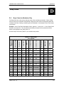
Appendix D - Strap Codes.......................................................................................... D-1
D.0 Strap Codes for Modulator Only ____________________________________________ D-1
D.1 Sample Applications _____________________________________________________ D-4
D.1.1 Operational Case Examples ______________________________________________ D-5
Glossary....................................................................................................................... G-1
TM138 – Rev. 1.0
xi
Table of Contents
xii
DMDVB20 LBST Satellite Modem
TM138 – Rev. 1.0
DMDVB20 LBST Satellite Modem
Introduction
Introduction
1
This chapter provides an overview of the DMDVB20 LBST Satellite Modem. The DMDVB20
LBST will be referred to in this manual as “the standard unit” and the DMDVB20 LBST will be
referred to as the LBST. When describing the DMDVB20 LBST, it may be referred to as “the
DMDVB20 LBST”, “the modem”, or “the unit”.
1.0 Overview
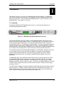
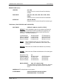
The Radyne DMDVB20 LBST Satellite Modem (Figure 1-1) offers the best features of a
sophisticated programmable modem.
Figure 1-1. DMDVB20 LBST Satellite Modem Front Panel
This versatile equipment package combines unsurpassed performance with numerous userfriendly Front Panel Programmable Functions. The DMDVB20 LBST provides different services
for the modulator and the demodulator. The modulator supported services are: Closed net,
Intelsat IBS and DVB -S. The demodulator support DVB-S2. All of the configuration and Monitor
and Control (M&C) Functions are available at the Front Panel. Operating parameters, such as
variable data rates, FEC Code Rate, modulation type, IF Frequencies, Framing and interface type
can be readily set and changed at the Front Panel by earth station operations personnel.
The modulator operates at all standard IBS Data Rates up to 8.448 Mbps. Selection of any data
rate is provided over the range of 2.4 Kbps to 20 Mbps in 1 bps steps. The Demodulator
supports DVB-S2 Broadcast Services. The DVB-S2 supports QPSK, 8PSK and 16APSK
applications with symbol rates of 2 to 20 Msps. Standard Interface available on the unit is
RS422/530.
The DMDVB20 LBST offers additional features that serves as an interface between the indoor
unit (DMDVB20 LBST) and the outdoor units (consisting of the BUC and LNB). The output
frequency of the LBST is 950 to 2050 MHz. The LBST TX port can supply voltage, 10 MHz
Reference and FSK to the BUC via the IFL cable. The RX port can supply LNB via the IFL Cable.
The BUC voltage supplied to the BUC can either be 24 or 48 Volts. The Rx Port LNB voltage
consists of 18 volts.
The LBST has the capability to enable and disable the BUC/LNB voltages and 10 MHz reference
via the front panel. In addition, monitoring features provide verification of system status. The
LBST monitors both the current and the voltage at the output of the Tx Port, thus allowing the
user to monitor the status of both the indoor units and outdoor units.
TM138 – Rev. 1.0
1-1
Introduction
DMDVB20 LBST Satellite Modem
1.1 Features/Options Installed at Time of Order
The DMDVB20 LBST can be configured in the following different ways:
•
•
•
•
features and options that are installed when the unit is ordered
feature upgrades
hardware options that are installed to a unit that is sent to a Radyne facility
hardware options that the user can install at their own location
Features installed at the time of ordering are the options pre-installed/initialized in the factory prior
to shipment. These can be reviewed from the front panel system menu. Refer to Section 4, User
Interfaces for information on how to view these features.
Factory installed options are chassis and board configurations that are introduced during
manufacturing.
1.1.1 Feature Upgrades
Feature Upgrades are soft upgrades that can be easily be enabled on the modem. Enabling new
features are done remotely or through the front panel of the modem. Features may be purchased
at any time by contacting a Radyne Corp. salesperson. Refer to Section 4 and Appendix D, for
information on how upgrade features are enabled.
1.1.2 Radyne Installed Options
Units may also be sent to the Radyne Corp. facility for hardware option installation. Please
contact the Radyne Corp. Customer Service Department for information pertaining to availability
and to shipping costs.
1.1.3 Hardware Options
Hardware options (refer to Appendix A) are purchased parts that can be installed into the unit at
the customer’s site. A screwdriver is normally the only tool required. Please contact the Radyne
Corp. Customer Service Department for information pertaining to availability and to shipping
costs.
Only authorized service personnel should handle and install optional
hardware options.
1.2 Function Accessibility
All functions can be accessed through the front panel, terminal or personal computer via a serial
link or via the Ethernet port offering a complete remote monitoring and control capability.
1-2
TM138 – Rev. 1.0
DMDVB20 LBST Satellite Modem
TM138 – Rev. 1.0
Introduction
1-3
DMDVB20 LBST Satellite Modem
Installation
Installation
2
This section provides unpacking and installation instructions, and a description of external
connections and backward alarm information.
2.0 Installation Requirements
The DMDVB20 LBST Modem is designed to be installed within any standard 19-inch (48.26 cm)
wide equipment cabinet or rack. It requires one rack unit (RU) of mounting space (1.75
inches/4.45 cm) vertically and 19.25 inches (48.89 cm) of depth for the DMDVB20 LBST and 24
inches (60.96 cm) of depth for the DMDVB20 LBST. The rear panel of the modem is has power
entering from the left and IF Cabling entering from the right (as viewed from the rear of the unit).
Data and Control Cabling can enter from either side.
PROPER GROUNDING PROTECTION: During installation and setup, the
user must ensure that the unit is properly grounded. The equipment
shall be connected to the protective earth connection through the end
use protective earth protection.
In addition, the IF input and output coax cable shielding must be properly
terminated to the Chassis/unit ground
There are no user-serviceable parts or configuration settings located
inside the Chassis. There is a potential shock hazard internally at the
power supply module.
DO NOT open the Chassis under any
circumstances.
TM138 – Rev. 1.0
2-1
Installation
DMDVB20 LBST Satellite Modem
Before initially applying power to the unit, it is a good idea to disconnect
the transmit output from the operating ground station equipment. This is
especially true if the current configuration settings are unknown, where
incorrect settings could disrupt existing communications traffic.
The modem contains a Lithium Battery. DANGER OF EXPLOSION exists
if the battery is incorrectly replaced. Replace only with the same or
equivalent type recommended by the manufacturer. Dispose of used
batteries in accordance with local and national regulations.
2.1 Unpacking
The Universal Satellite Modem was carefully packaged to avoid damage and should arrive
complete with the following items for proper installation:
Modem Unit
Power Cord, with applicable AC Connector
Installation and Operation Manual
2.2 Removal and Assembly
The Modem is shipped fully assembled. It does not require removal of the covers for any
purpose in installation.
Always ensure that power is removed from the before removing or
installing any optional modules. Failure to do so may cause damage to
the equipment.
Carefully unpack the unit and ensure that all of the above items are in the carton. If the available
AC mains power at the installation site requires a different cord set from the one included in the
package, then a suitable and approved cord set (for the country where the equipment is to be
installed) will be required before proceeding with the installation.
2-2
TM138 – Rev. 1.0
DMDVB20 LBST Satellite Modem
Installation
Should the Power Cable/AC Connector be of the wrong type for the installation, either the cable
or the power connector end should be replaced. The power supply itself is designed for universal
AC application. See specifications for appropriate voltages and currents.
2.3 Mounting Considerations
When mounted in an equipment rack, adequate ventilation must be provided. The ambient
temperature in the rack should preferably be between 10° and 35°C, and held constant for best
equipment operation. The air available to the rack should be clean and relatively dry. The
modems may be stacked one on top of the other to a maximum of 10 consecutive units before
providing one (1) RU of space for airflow. Modems should not be placed immediately above a
high-heat or EMF Generator to ensure the output signal integrity and proper receive operation.
Do not mount the in an unprotected outdoor location where there is direct contact with rain, snow,
wind or sun. The only tools required for rack mounting are four (4) customer supplied rackmounting screws and the appropriate screwdriver. Rack mounting brackets are an integral part of
the front bezel of the unit and are not removable.
2.4 Initial Configuration Check
The modem is shipped from the factory with preset factory defaults. Upon initial power-up, a user
check should be performed to verify the shipped modem configuration. Refer to Section 4, User
Interfaces to locate and verify that the following configuration settings are correct:
The Interface Type (V.35, RS-422, RS-232, etc.) MUST be selected from the
Front Panel BEFORE the mating connectors are installed. Failure to do so
may cause damage to the Universal Interface Module. Power up the
modem, select the appropriate interface type, and then install the mating
connectors.
Transmit (Tx) and Receive (Rx) Interface types are dependent upon the
customer’s order.
TM138 – Rev. 1.0
2-3
Installation
DMDVB20 LBST Satellite Modem
Standard Factory Configuration Settings
Modulator:
Data Rate:
Mode:
Frequency:
Modulation:
Inner FEC:
Satellite Framing:
Scrambler:
Reed Solomon:
Modulator Output Power:
2.048 Mbps
Closed Network
1200 MHz
QPSK
1/2 Rate Viterbi
None
V.35 (IESS)
Disabled
-20 dBm
Demodulator:
Data Rate:
Mode:
Frequency:
Modulation:
Inner FEC:
Satellite Framing:
Terrestrial Framing:
Pilot Symbols:
2.048 Mbps
DVB S2
1200 MHz
QPSK
1/2 Rate S2
DVB S2 Normal
None
Disabled
Usage of the modems loopback capabilities in conjunction with the
Ethernet data interface can produce undesirable network loops. In order
to run any type of data test with an Ethernet interface you must utilize
two modems connected back to back. Simply using one modem and a
loopback will not produce the desired results.
2-4
TM138 – Rev. 1.0
DMDVB20 LBST Satellite Modem
Installation
2.5 Modulator Checkout
The following descriptions assume that the modem is installed in a suitable location with prime
AC power and supporting equipment available.
2.5.1 Initial Power-Up
Before initial power up of the modem, it is a good idea to disconnect the
transmit output from the operating ground station equipment. This is
especially true if the current Modulator Configuration Settings are
unknown, where incorrect settings could disrupt the existing
communications traffic. New units from the factory are normally shipped
in a default configuration which includes setting the transmit carrier off.
Turn on the unit by placing the Rear Panel Switch (located above the power entry connector) to
the On Position. Upon initial and subsequent power-ups, the Microprocessor will test itself and
several of its components before beginning its Main Monitor/Control Program. These power-up
diagnostics show no results if successful. If a failure is detected, the Fault LED will illuminate.
The initial field checkout of the modem can be accomplished from the Front Panel or in the
Terminal Mode. The Terminal Mode has the advantage of providing full screen access to all of
the modem’s parameters, but requires a separate terminal or computer running a Terminal
Program. The Terminal Mode is enabled from the front panel in the System M&C Submenus.
2.5.2 Factory Terminal Setup
The factory terminal setup is as follows:
Emulation Type:
Baud Rate:
Data Bits:
Parity:
Stop Bits:
VT-100 (can be changed)
19.2 K (Can be changed via Front Panel)
8
No Parity (Fixed)
1 Stop Bit
2.6 Storage
It is recommended that the unit be stored in its original sealed packing. The unit should be stored
in a dry location where the temperature is stable, away from direct contact with rain, snow, wind,
sun, or anything that may cause damage.
TM138 – Rev. 1.0
2-5
Installation
2-6
DMDVB20 LBST Satellite Modem
TM138 – Rev. 1.0
DMDVB20 LBST Satellite Modem
Theory of Operation
3
Theory of Operation
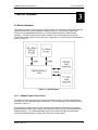
3.0 Modem Hardware
The modem is based on a two printed circuit card (minimum configuration) design with additional
optioned printed circuit cards available for additional features. The minimum configuration
consists of a Digital Baseband assembly, Tx L-Band assembly and RX L-Band Receiver
assembly. The optional printed circuit cards include a Turbo Codec printed circuit card an
optional data interface printed circuit card (refer to Appendix A). A block diagram of the Modem is
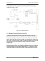
shown in Figure 3.1.
Figure 3-1. Block Diagram
3.0.1 L-Band Printed Circuit Card
The L-Band circuit cards consists of an analog modulation function, an analog complex down
conversion, and two wide-band digital synthesizers. The block diagram of the L-Band assembly
is shown in Figure 3-2.
In the modulator, analog in-phase (I) and quadrature (Q) signals are generated on the Digital
Baseband Printed Circuit Card, routed to the L-Band Printed Circuit Card, and modulated at the
desired frequency. The L-Band modulated signal is then passed through a microprocessor
controlled variable attenuator providing gain control of the output signal.
TM138 – Rev. 1.0
3-1
Theory of Operation
DMDVB20 LBST Satellite Modem
In the complex downconverter, the signal for demodulation is amplified and sent through a
variable wideband attenuator for AGC. The gain-controlled signal is then passed through a
complex downconverter to a low IF.
Figure 3-2. IF Card Block Diagram
3.0.2 Baseband Processing Printed Circuit Card
The advent of million-plus gate count FPGAs, advanced logic synthesis tools, and DSPs
providing hundreds of MIPs enabled the design of a software configurable modem. Large, fast
FPGAs now provide designers with what is essentially an on the fly programmable ASIC. High
speed, complex digital logic functions that previously could only be implemented in dedicated
integrated circuits are now downloaded from a micro-controller through a serial or peripheral
interface. When a new digital logic function is needed, a new configuration file is loaded into the
FPGA. There is no limit to the number of digital logic configurations available to the FPGA, aside
from the amount of Flash memory available to the system microprocessor for storage of
configuration files.
The Baseband Processing Printed Circuit Card provides a flexible architecture that allows
different modes of terrestrial and satellite framing, various FEC options, and several different
modulation/demodulation formats. Also included on the Baseband Printed Circuit Card are three
synchronous interfaces, an EIA-530 Interface supporting RS-422, V.35, and RS-232. All three
interfaces are provided on the same DB-25 Connector, and are selectable from the front panel.
3-2
TM138 – Rev. 1.0
DMDVB20 LBST Satellite Modem
Theory of Operation
The Baseband Printed Circuit Card also contains the Monitor and Control (M&C) Circuitry
responsible for:
Programmable part setup and initialization
Continuous control and adjustment of some functions
Calibration
Monitoring fault status
Calculating and displaying measurements
User monitor and control interface including front panel and remote
Units configuration and feature set
The M&C System is based on a powerful microprocessor with a large amount of Flash memory.
Several bus architectures are used to interconnect the M&C to all components of the modem.
Communication to the outside world is done via connections to the remote port, terminal port,
Ethernet port, and alarm ports. The M&C runs off of software programmed into its Flash memory.
The memory can be reprogrammed via the Ethernet port to facilitate changes in software.
3.0.3 Enhanced Interface Printed Circuit Card
The normal terrestrial data for the Baseband Processing Card can be re-routed to the enhanced
interface card. The enhanced interface card adds a variety of connections to the modem for
additional applications
3.1 Functional Block Diagram
Figure 3-3 represents the Functional Blocks. The modem is shown in a typical application with
customer data, Tx/Rx RF equipment and an antenna.
TM138 – Rev. 1.0
3-3
Theory of Operation
DMDVB20 LBST Satellite Modem
Figure 3-3. Satellite Modem Functional Block Diagram
3.1.1 Front Panel
The Front Panel includes a 2 x 16 backlit LCD Display, Indicator LEDs, and a Numeric Keypad
(refer to Section 4.1).
3.1.2 Baseband Processing
The Baseband Processor performs all Modulator functions required for an IBS Framing Unit, and
Reed-Solomon Codec. In addition, the Baseband Processing Section provides for transmit clock
selection and rate adaptation as well as a rate adapter and Plesiochronous/Doppler (PD) Buffer in
the receive direction. A multiplexer is also provided for the SCT Clock Source for Loop Timing
Applications. The transmit and receive paths are configured independently under processor
control.
3-4
TM138 – Rev. 1.0
DMDVB20 LBST Satellite Modem
Theory of Operation
3.1.3 Tx Baseband Processing
The Tx Data and Clock enters the Baseband Processor, passes through a Rate Adapting FIFO
and enters the Framer/Drop Processor. In IBS mode, the framer adds the appropriate framing as
defined in 309. The data is then sent to the Reed-Solomon Encoder.
When enabled, the Reed-Solomon Encoder, encodes the data into Reed-Solomon Blocks. The
blocks are then interleaved and synchronized to the frame pattern as defined by the selected
specification (IESS-309, DVB, etc.). After Reed-Solomon Encoding, the composite data and
clock are applied to the BB Loopback Circuit.
3.1.4 Rx Baseband Processing
The Receive Processor performs the inverse function of the Tx Processor. Data received from
the satellite passes through the LDPC Receiver to the Decoder/Deframer. The Deframer
acquires the LDPC frame, and extracts the received data, placing the data into the PD Buffer,
sending the overhead data to the UIM. The data is extracted from the buffer and is sent to the
UIM.
3.2 Monitor & Control (M&C) Subsystem
The modems M&C system is connected to most of the circuitry on any board contained in the
modem. These connections provide status on the working condition of the circuitry as well as
providing the data required for the various measurements the modem provides. The M&C
processes this information and generates status indications as well as alarms when necessary.
Detailed status information is available via the modems various user interfaces including the
remote and terminal ports. An external summary fault is available on the RS422 Data interface
The M&C contains a high-performance microprocessor and is responsible for overall command
and control of modem functions. The M&C is constantly monitoring all subsystems of the modem
by performing a periodic poll routine and configures the modem by responding to commands
input to the system. During each poll cycle, the status of each of the subsystems is collected and
reported to each of the external ports. Performance statistics such as Eb/No, buffer fill %, etc.
are compiled. If faults are detected, the M&C will take appropriate actions to minimize the effect
of such faults on the system (refer to the Fault Matrices in Section 6).
The modem supports the following M&C protocols:
TM138 – Rev. 1.0
Terminal Interface (Section 3.2.1)
Remote Port Interface (Section 3.2.2)
Modem Status, Alarms & Contact Closures (Section 3.2.4)
3-5
Theory of Operation
DMDVB20 LBST Satellite Modem
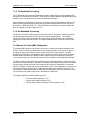
3.2.1 Terminal Port (Supported in Rev B or greater)
This port supports an asynchronous control protocol as described in Section 4. It is configured to
support RS-232 signal levels. This port is intended for use in computer-based remote M&C. All
functions of the modem may be monitored and controlled from this port via a common terminal
connected to the Terminal Port. This function is front panel selectable.
The Terminal Mode Control allows the use of an external terminal or computer to monitor and
control the modem from a full screen interactive presentation operated by the modem itself. No
external software is required other than VT-100 Terminal Emulation Software (e.g. “Procomm”
for a computer when used as a terminal. The Control Port is normally used as an RS–232
Connection to the terminal device. The RS-232 operating parameters can be set using the
modem Front Panel and stored in Non-volatile memory for future use.
Refer to the Remote Protocol Manual (TM137) for the Terminal and
Remote screens and protocols.
3.2.2 Modem Remote Communications (RLLP)
The Remote Port located on J20 allows for control and monitoring of parameters and functions
via an RS-232 Serial Interface, or RS-485 for RLLP Protocol. ‘Equipment Remote Mode’ setup
can be entered from the front panel under the “System” menu. This requires the user to first set
the Remote Port Control to “Remote” then set the Multidrop Address as needed followed by
setting the Remote Interface to RS232 or RS485.
Control and status messages are conveyed between the modem and all subsidiary modems and
the host computer using packetized message blocks in accordance with a proprietary
communications specification. This communication is handled by the Radyne Link Level Protocol
(RLLP), which serves as a protocol ‘wrapper’ for the RM&C data. Complete information on
monitor and control software is contained in the following sections.
3.2.3 Ethernet M&C Port (Not Supported)
3.2.4 Modem Monitor Status
The modems M&C system is connected to most of the circuitry on any board contained in the
chassis. These connections provide status on the working condition of the circuitry as well as
providing the data required for the various measurements the modem provides. The M&C
processes this information and generates status indications as well as alarms when necessary.
Detailed status information is available via the modems various user interfaces (front panel,
remote and terminal). A summary of this information can be connected to external equipment,
switches or alarms via the open collector and/or form-C fault connections
Form-C Contacts:
The UIM provides three Form-C Relays under processor control that appear at J15.
3-6
TM138 – Rev. 1.0
DMDVB20 LBST Satellite Modem
Theory of Operation
Mod Fault:
De-energized when any transmit side fault is detected.
Demod Fault:
De-energized when any receive side fault is detected.
Common Fault:
De-energized when any fault that is not explicitly a Tx or
Rx Fault such as an M&C or Power Supply Fault.
Open Collector Faults:
The UIM provides two Open Collector Faults that appear at Pins 18 & 21 on J19.
Mod Fault:
Will sink up to 20 ma (maximum) until a transmit or
common fault is detected. Will not sink current if a fault
is detected.
Demod Fault:
Will sink up to 20 ma (maximum) until a receive or
common fault is detected. Will not sink current if a fault
is detected.
The open collector faults are intended for use in redundancy switch applications in order to
provide quick status indications.
3.3 Internal Clock
The time and date is kept in order to ‘time-tag’ system events. User can change the Internal
Clock via the front panel or Terminal ports.
TM138 – Rev. 1.0
3-7
Theory of Operation
DMDVB20 LBST Satellite Modem
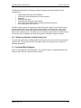
3.4 Loopback Features (Terrestrial)
The modem provides for a number of different loopbacks. The Loopback supported are:
TX Terrestrial Loopback - Tx Data port is looped back to the Rx Data port after the
interface driver/receiver. (prior to the framing unit)
TX Baseband Loopback - Tx Data port is looped back to the Rx Data port after the
interface driver/receiver. (after the framing unit)
RX Terrestrial Loopback - Receive Data from the satellite is looped back for
retransmission to the satellite, providing a far end loopback. (prior to the framing
unit)
RX Baseband Loopback - Receive Data from the satellite is looped back for
retransmission to the satellite, providing a far end loopback. (after to framing unit)
Usage of the modems loopback capabilities in conjunction with the
Ethernet data interface can produce undesirable network loops. In order
to run any type of data test with an Ethernet interface you must utilize
two modems connected back to back. Simply using one modem and a
loopback will not produce the desired results.
3-8
TM138 – Rev. 1.0
DMDVB20 LBST Satellite Modem
Theory of Operation
Figure 3-5. Loopback Functional Block Diagram
TM138 – Rev. 1.0
3-9
Theory of Operation
DMDVB20 LBST Satellite Modem
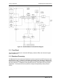
3.5 Clocking Options
The modem supports a number of different clocking options that can be recovered from
the satellite or the terrestrial links. The various clocking options allow users to determine
which clock will best fit their applications. Figure 3-6 gives an overview on how the
modem processes the various clocks for the Tx Clock source and the Rx Buffer Clock
source. Tx and Rx Clocks may be independently locked.
Figure 3-6. Clocking and Polarity Diagram
3.5.1 TX Clock Options
TX clock options can be recovered from the terrestrial interface, satellite interface or internally
generated. The allows users to select SCTE Clock (Terrestrial) or the SCT internal clock. The
modem also allows user to recover the SCT Clock from the satellite (SCR) or from the modem
internally. The modem allows users to select clock polarity. The Tx clock selections available
are:
3-10
TM138 – Rev. 1.0
DMDVB20 LBST Satellite Modem
Theory of Operation
The following paragraphs define the types of clocking options available to the user at the Front
Panel.
SCT (Internal Oscillator)
SCTE (External Tx Terrestrial Clock)
Rx Satellite Clock
3.5.1.1 SCTE: Serial Clock Transmit External
The SCTE clock is the Transmit Terrestrial Clock associated with the data interface. SCTE is an
external clock received from the terrestrial equipment and the modem utilizes the terrestrial clock
to lock the internal clock.
In Figure 3-7, the Transmit Terrestrial Data enters the modem and is clocked into a dejitter FIFO.
Data is clocked out of the FIFO by the Modulator Clock. The Modulator Clock and Phase-Locked
Loop (PLL), in conjunction with the Dejitter FIFO, which reduces the input jitter. Jitter reduction
exceeds the jitter transfer specified in CCITT G.821.
SCTE is sometimes referred to as Tx Terrestrial Timing or Terminal Timing. Terminal Timing is
reference to the RS422 synchronous interfaces.
3.5.1.2 SCT: Serial Clock Transmit
The SCT clock can be generated internally or recovered from the satellite. The SCT clock source
can be used as the TX clock source, RX Buffer Clock source and the Terrestrial Terminal
equipment for clocking the transmit data. If the SCT clock is recovered from the satellite, then it
is referred to as SCR. SCR is also referred to as Receive Clock, Satellite Clock, or Receive
Timing (RT).
When SCT clock is configured as Internal, the frequency of the clock is set the same as the
Transmit Terrestrial Clock rate. If SCT clock is configured as SCR, the internal clock is set to the
same rate as the incoming receive satellite clock. SCT is sometimes referred to as Internal
Timing or Send Timing (ST). In the event that the satellite clock is lost, the modem will
automatically switch over to the Internal Clock and revert back to SCR when activity is detected.
If SCT is selected, then Terrestrial data that is synchronous to the SCT Clock is required to be
supplied by the modem. It is intended for the terminal equipment to use the SCT as its clock
source. The Autophase Circuit will automatically ensure that the data is clocked correctly into the
modem. Therefore, a return clock is not necessary. The Clock Polarity should be set to Auto.
3.5.2 RX Buffer Clock Options
The modem supports a number of RX Buffer clock options that can be recovered from the
satellite, terrestrial links, internally or externally. The various clocking options allow users to
determine which clock will best fit their applications. Figure 3-7 gives an overview on how the
modem processes the various clocks for the Tx Clock and the Rx Buffer Clock. The modem
allows users to select clock polarity Tx and Rx Clocks may be independently locked. The
following RX Buffer clock selections are available:
TM138 – Rev. 1.0
Rx Satellite Clock (Recovered from Satellite)
3-11
Theory of Operation
DMDVB20 LBST Satellite Modem
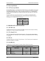
The modem handles RX Buffer clock selections based on source priority levels. The user
assigns priorities to the clock sources based on source selections. Source 1 has the highest
priority and Source 4 being the last resort or lowest priority. If a fallback clock is selected and
activity is lost at the highest priority source, the modem will fall back to the next highest priority
clock with activity. When activity resumes on a higher priority source, the modem resumes using
the higher priority source
Clock Source
RX SAT
SCTE
SCT
EXC BNC
1
2
3
4
Priority
of
of
of
of
4
4
4
4
3.5.2.1 RX SAT Clock
The RX Sat clock is recovered from the satellite that is received from the distant end. If selected
the Buffer Clock is lock to the RX sat clock.
3.5.3 EXT REF: External Reference, Top BNC Port, J10
This is not actually a clock, but does have some clocking implications. When the external
reference is used, the master oscillator within the modem is locked to the external reference, and
the internal accuracy and stability of the unit assumes that of the External Reference. Therefore,
not only are the transmit frequencies locked to the external reference, but the modem’s internal
SCT Oscillator is locked to the external reference as well.
External reference port input is specified at 0 to +6 dBm.
3.6 RS530/422/V.35 Interface (Standard)
Data must be clocked into the modem by either the SCTE or SCT Source. If SCTE is selected as
the Tx Clock Source, then SCTE must be supplied to the modem on the EIA-530 port. The output
of the dejitter buffer will be clocked with this source. SCT should be used if SCTE has excessive
jitter.
3-12
TM138 – Rev. 1.0
DMDVB20 LBST Satellite Modem
Theory of Operation
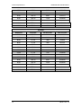
3.7 Reed-Solomon Codec (TX Only)
Reed Solomon only pertains to TX options.
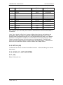
Refer to Figures 3-8, 3-9, and Table 3-1.
Utilizing a Reed-Solomon (R-S) Outer Codec concatenated with a Convolutional Inner Codec is
an effective way to produce very low error rates even for poor signal-to-noise ratios while
requiring only a small increase in transmission bandwidth. Typically, concatenating an R-S
Codec requires an increase in transmission bandwidth of only 9 – 12% while producing a greater
than 2 dB improvement in Eb/No. R-S is a block Codec where K data bytes are fed into the
encoder which adds 2t = (N – K) check bytes to produce an N byte R-S block. The R-S decoder
can then correct up to “t” erred bytes in the block.
3.7.1 Reed-Solomon Operation
When the Reed-Solomon Codec is enabled, data is fed to the R-S Encoding Section where it is
scrambled, formed into blocks, R-S encoded, and interleaved. Unique words are added so that
the blocks can be reformed in the Receiving Modem (Refer to Figures 3-7 and 3-8). Data is then
sent to the modulator where it is convolutionally encoded, modulated and transmitted to the
satellite.
When the signal is received and demodulated by the Receiving Modem, it is fed to a Viterbi
Decoder for the first layer of error correction. After error correction is performed by the Viterbi
Decoder, the unique words are located and the data is deinterleaved and reformed into blocks.
The R-S Decoder then corrects the leftover errors in each block. The data is then descrambled
and output from the R-S Section.
3.7.2 Reed-Solomon Code Rate
The R-S Code Rate is defined by (N, K) where N is the total R-S block size in bytes - data +
check bytes - and K is the number of data bytes input into the R-S Encoder. The transmission
rate expansion required by the R-S Codec is then defined by N/K. The modem automatically sets
the correct R-S code rate for IBS open network operation in accordance with the data shown in
Table 3-1. The modem allows the following N and K setting: (126, 112), (219, 201), (194, 178),
(225, 205).
Variable Reed-Solomon rates are available on the optional AS/5167 Super Card. Refer to
Appendix A for further information.
3.7.3 Interleaving
Interleaving depths of 4, 8, or 12 R-S blocks are allowed. This allows burst errors to be spread
over multiple blocks in order to enhance the error correcting performance of the R-S Codec. For
Intelsat Network Modes, the interleaving depth is automatically set to 4 for QPSK or BPSK, or 8
for 8PSK. In Closed Network Mode, the interleaver depth can be manually set to 4 or 8, and in
DVB Network Mode, the interleaver depth is automatically set to 12.
TM138 – Rev. 1.0
3-13
Theory of Operation
DMDVB20 LBST Satellite Modem
Figure 3-7. Reed-Solomon Encoder Functional Block Diagram
Figure 3-8. Reed-Solomon Decoder Functional Block Diagram
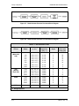
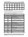
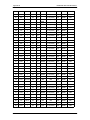
Table 3-1. Reed-Solomon Codes
Type of
Service
Data Rate
(Kbps)
R-S Code
(n, k, t) 1
Bandwidth
Expansion
[ (n/k) -1 ]
Interleaving
Depth
Maximum 2
R-S Codec
Delay (ms)
Small IDR
(With 16/15
O/H)
64
128
256
384
512
768
1024
1536
(126, 112, 7)
(126, 112, 7)
(126, 112, 7)
(126, 112, 7)
(126, 112, 7)
(126, 112, 7)
(126, 112, 7)
(126, 112, 7)
0.125
0.125
0.125
0.125
0.125
0.125
0.125
0.125
4
4
4
4
4
4
4
4
115
58
29
19
15
10
8
5
IDR
(With 96
Kbps O/H)
1544
2048
6312
8448
(225, 205,10)
(219, 201, 9)
(194, 178, 8)
(194, 178, 8)
0.0976
0.0896
0.0899
0.0899
4
4
4
4
9
7
2
<2
8PSK
1544
2048
6312
8448
(219, 201, 9)
(219, 201, 9)
(219, 201, 9)
(219, 201, 9)
0.0896
0.0896
0.0896
0.0896
8
8
8
8
18
13
4
3
DVB
All
(204, 188, 8)
0.0851
12
-
1. n = code length, k = information symbols and t = symbol error correcting capability.
2. Design objective.
3-14
TM138 – Rev. 1.0
DMDVB20 LBST Satellite Modem
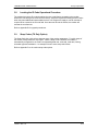
3.8
Theory of Operation
Locating the ID Code Operational Procedure
The modem has unique ID codes that allow the user to add feature upgrades to the modem
without the unit having to be returned to the factory. Users are required to identify these ID codes
when they want additional features added to their unit. Radyne will supply a new ID code that is
required to be entered in the ID code field. Once the new ID code is entered, the modem will
activate the new features.
Refer to Appendix B for upgrade procedures.
3.9
Strap Codes (TX Only Option)
The Strap Code is a quick set key that sets many of the modem parameters. For quick setup of
the modem, Strap Codes are very helpful. When a Strap Code is entered, the modem is
automatically configured for the code’s corresponding data rate, overhead, code rate, framing,
scrambler type and modulation. An example of how to set a strap code follows:
Refer to Appendix D or the various strap code options.
TM138 – Rev. 1.0
3-15
Theory of Operation
3-16
DMDVB20 LBST Satellite Modem
TM138 – Rev. 1.0
DMDVB20 LBST Satellite Modem
User Interfaces
4
User Interfaces
4.0 User Interfaces
This section contains information pertaining to the user interfaces for the modem. There are four
user interfaces available for the modem. These are:
•
•
•
Front Panel Interface – Refer to section 4.1.
Terminal Interface - :Refer to section 4.4.
RS485 Remote Port Interface (RLLP) – Refer to the Section 4.6.
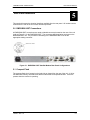
4.1 Front Panel User Interface
The Front Panel of the DMDVB20 LBST allows for complete control and monitor of all DMDVB20
LBST parameters and functions via a keypad, LCD display and status LEDs.
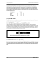
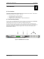
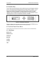
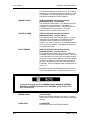
The front panel layout is shown in Figure 4-1 and 4-2 showing the location and labeling of the
front panel. The front panel is divided into four functional areas: the LCD Front Panel Display, the
Cursor Control Arrow Keys, the Numeric Keypad, and the Front Panel LED Indicators, each
described below in Table 4-1.
1
2
3
4
Figure 4-2. DMDVB20 LBST Front Panel
TM138 – Rev. 1.0
4-1
User Interfaces
DMDVB20 LBST Satellite Modem
Table 4-1.
Item Number
Description
Function
1
LCD Front Panel Display
Displays operating parameters and
Configuration data
2
Cursor Control Arrow Keys
Controls the up, down, right and left motion
of the cursor in the LCD Display window
3
Numeric Keypad
Allows entry of numeric data and Clear and
Enter function keys
4
Front Panel LED Indicators
See Paragraph 4.1.4 below for an itemized
description of these LEDs
4.1.1 LCD Front Panel Display
The front panel display is a 2 line by 16-character LCD display. The display is lighted and the
brightness can be set to increase when the front panel is currently in use.
The LCD display automatically dims after a period of inactivity. The display has two distinct areas
showing current information. The upper area shows the current parameter being monitored, such
as ‘Frequency’ or ‘Data Rate’. The lower line shows the current value of that parameter. The
LCD display is a single entry window into the large matrix of parameters that can be monitored
and set from the Front Panel.
4.1.2 Cursor Control Arrow Keys
A set of ‘Arrow’ or ‘Cursor’ keys (↑), (↓), (→), (←), is used to navigate the parameter currently
being monitored or controlled. Table 4-2 describes the functions available at the Front Panel.
4.1.3 Numeric Keypad
A 10-Key Numeric Keypad with two additional keys for the ‘Enter’ and ‘Clear’ function allows the
entry of data into the system. Table 4-2 describes the functions available at the Front Panel.
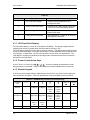
Table 4-2. Edit Mode Key Functions (Front Panel Only)
Parameter
Type
0–9
↑
Fixed Point Changes Digit Toggles ±
Decimal
(If Signed)
↓
←
→
‘Clear’ &
←
‘Clear’ &
→
Toggles ±
(If Signed)
Moves
Cursor 1
Position
Left
Moves
Cursor 1
Position
Right
N/A
N/A
Moves
Cursor 1
Position
Left
Moves
Cursor 1
Position
Right
N/A
N/A
Unsigned Changes Digit Increments Decrements
Hexadecimal
Digit Value Digit Value
Enumerated
N/A
Date/ Time Changes Digit
4-2
Previous
Value in
List
Next
Value in
List
N/A
N/A
N/A
N/A
N/A
N/A
Moves
Moves
N/A
N/A
TM138 – Rev. 1.0
DMDVB20 LBST Satellite Modem
User Interfaces
Cursor 1
Position
Left
Cursor 1
Position
Right
IP Address Changes Digit Increments Decrements
Digit Value Digit Value
Moves
Cursor 1
Position
Left
Moves
Cursor 1
Position
Right
N/A
N/A
Text Strings
Moves
Cursor 1
Position
Left
Moves
Cursor 1
Position
Right
Clears to
Left of
Cursor
Inclusive
Clears to
Right of
Cursor
Inclusive
Changes
Character
Increments Decrements
Character
Character
Value
Value
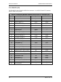
4.1.4 Front Panel LED Indicators
Twelve LEDs on the Front Panel (Refer to Table 4-3) indicate the status of operation. The LED
colors maintain a consistent meaning. Green signifies that the indication is appropriate for normal
operation, Yellow means that there is a condition not proper for normal operation, and Red
indicates a fault condition that will result in lost communications.
Table 4-3.
LED
Color
Function
Modem LED Indicators
Power
Green
Indicates that the unit is turned on.
Fault
Red
Event
Yellow
Indicates that a condition or event has occurred that the
modem has stored in memory. The events may be viewed
from the Front Panel or in the Terminal Mode.
Remote
Green
Indicates that the unit is in the process of updating firmware
with FTP or flashing indicates some features are demo
enabled.
Indicates a hardware fault for the unit.
Modulator LED Indicators
Transmit On
Green
Indicates that the transmitter is on.
Major Alarm
Red
Minor Alarm
Yellow
Indicates that a Transmit Warning Condition exists.
Test Mode
Yellow
Indicates that the transmitter is involved in a current Test
Mode activity.
Indicates that the Transmit Direction has failed, losing traffic.
Demodulator LED Indicators
Signal Lock
Green
Indicates that the receiver locked to an incoming carrier and
data, including FEC Sync.
Major Alarm
Red
Indicates that the Receive Direction has failed, losing traffic.
Minor Alarm
Yellow
Indicates that a Receive Warning Condition exists.
Test Mode
Yellow
Indicates that the receiver is involved in a current Test Mode
activity.
TM138 – Rev. 1.0
4-3
User Interfaces
DMDVB20 LBST Satellite Modem
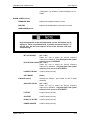
4.2 Parameter Setup
The four Cursor Control Arrow Keys are used to navigate the menu tree and select the parameter
to be set. After arriving at a parameter that needs to be modified, depress <ENTER>. The first
space of the modifiable parameter highlights (blinks) and is ready for a new parameter to be
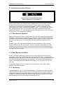
entered. After entering the new parameter using the keypad (Refer to Figure 4-2), depress
<ENTER> to lock in the new parameter. If a change needs to be made prior to pressing
<ENTER>, depress <CLEAR> and the display defaults back to the original parameter. Depress
<ENTER> again and re-enter the new parameters followed by <ENTER>.
Figure 4-2. Entering New Parameters
Following a valid input, the unit will place the new setting into the nonvolatile EEPROM making it
available immediately and available the next time the unit is powered-up.
4.3 Front Panel Control Screen Menus
The Front Panel Control Screens are broken down into sections under several Main Menus.
4.3.1 Main Menus
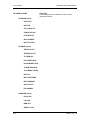
MODULATOR
DEMODULATOR
INTERFACE
MONITOR
ALARMS
SYSTEM
TEST
4-4
TM138 – Rev. 1.0
DMDVB20 LBST Satellite Modem
User Interfaces
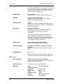
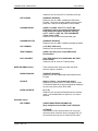
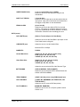
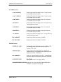
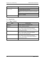
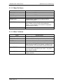
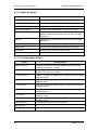
4.3.2 Modulator Menu Options and Parameters
NETWORK SPEC
{CLOSED NET, DVB SAT}
The Network Spec Command sets a number of
parameters within the modem to meet a specification.
The purpose is to eliminate keystrokes and potential
compatibility problems.
Data rates not covered by a given network specification
will not be allowed. If the mode of operation is selected
after the data rate has been entered, then the data rate
must be compatible with the desired mode of operation
or the network spec will not be allowed. The following
parameters cannot be changed while the unit is in the
given mode of operation:
DVB: Per EN301-421 & En301-210
Data Rates:
Framing Type:
Scrambler Type:
Spectrum Mask:
All Rates
DVB
DVB
DVB 0.25, 0.35
Closed Net:
All possible combinations allowed, however, a DVB
setting requires the DVB network spec. Activates the
AUPC Menu.
STRAP CODE
{Refer to Strap Code Guide, Appendix H}
The Strap Code is a quick set key that sets many
modem parameters. Consult the strap code guide for
available strap codes. Parameters set by strap code:
Data Rate
Inner Code Rate
Satellite Framing
Scrambler
Outer Code Rate (Reed-Solomon)
Modulation
Network Spec
IF (menu)
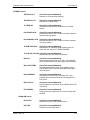
FREQUENCY (MHz)
{950 - 2050 MHz}
Allows the user to enter the Modulator IF Output
Frequency of the modem in 1 Hz increments.
UPLINK FREQ
TM138 – Rev. 1.0
Displays the output frequency of the BUC also referred
to as Satellite uplink frequency. The user must enter the
BUC LO and OSC SIDE BAND before using this menu.
4-5
User Interfaces
DMDVB20 LBST Satellite Modem
The UPLINK FREQUENCY is a calculated measurement
of both the BUC LO and OSC SIDE BAND. Once the
menus are entered correctly, the user can control the
uplink Frequency from this menu.
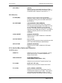
POWER (dBm)
{0 to -25 dBm}
Allows the user to enter the Transmitter Power Level.
CARRIER
{ON, OFF, AUTO, VSAT, RTS}
Allows the user to select the carrier type. Refer to
Appendix C for further information.
CARR DLY(SEC)
{0-255}
Allows the user to select the time delay after power-up
before the Tx Carrier may be enabled. This allows time
for the BUC to stabilize.
SPECTRUM
{NORMAL, INVERTED}
Allows the user to invert the direction of rotation for
QPSK Modulation. Normal meets the IESS
Specification.
Spectral inversion may be required if the BUC LO is
higher in frequency than the BUC output frequency.
When BUC LO is higher than the BUC output frequency,
this creates a spectral inversion and the IF Spectrum
must be again inverted to compensate.
MODULATION
{QPSK, BPSK, OQPSK, 8PSK, 16QAM}
Allows the user to select the modulation type.
SPECTRAL MASK
{Intelsat 0.35, DVB SAT 0.35, DVB SAT 0.25, DVB
SAT 0.20}
Allows the user to set the spectral shape of Tx Data
Filter.
COMPENSATION
{0.0 – 1.0}
Allows you to offset output power by up to 1 dBm. This
is intended as a correction for user cabinet connectors.
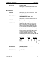
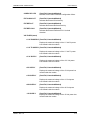
DATA (menu)
4-6
DATA RATE (bps)
{Refer to Technical Specs for Data Rates}
Allows the user to set the Data Rate in bps steps via the
Front Panel Arrows or Keypad.
SYMB RATE (sps)
Allows the user to view the Symbol Rate.
INNER FEC
Viterbi
Optional FEC Rates:
Sequential
Trellis 8PSK
Turbo
Comstream Seq
DVB VIT
DVB Trellis
{1/2, 3/4, 7/8, None}
{1/2, 3/4, 7/8}
{2/3}
{1/2, 3/4, 7/8}
{3/4}
{1/2, 2/3, 3/4, 5/6, 7/8}
{2/3, 5/6, 8/9}
TM138 – Rev. 1.0
DMDVB20 LBST Satellite Modem
User Interfaces
Allows the user to select the Tx Code Rate and Type
DIFF CODING
{ENABLED, DISABLE}
Allows the user to enable or disable the Differential
Encoder. Having the encoder enabled ensures proper
phase lock. May not be adjustable in some modes.
SCRAMBLER SEL
{NONE, V.35-IESS, V.35 CITT, V.35 EF, IBS
w/Optional Framing and optional Reed-Solomon,
Reed-Solomon Scrambler w/Optional Framing,
CCITT, V.35FC, V.35EF_RS, TPC SCRAMBLER
(Turbo Codec), DVB}
Allows the user to select the descrambler type.
SCRAMBLER CTRL
{ENABLED, DISABLE}
Allows the user to enable or disable scrambler operation.
SAT FRAMING
{1/15 (IBS), DVB, None}
Allows the user to select the framing type.
TERR FRAMING
{NONE, 188, 204}, when using DVB Network
Specifications
DATA POLARITY
{INV. TERR & BASE, INV. BASEBAND, INV.TERR
DATA, NONE}
Allows the user to invert the Tx Data polarity.
REED-SOLOMON (menu)
These selections are visible only when the ReedSolomon Option is installed.
ENABLE/DISABLE
{ENABLED, DISABLE}
Allows the user to Enable/Disable the Reed-Solomon
Encoder.
RS RATE
{Refer to Table 3-1 for standard n/k values}
Displays the currently used n, k Reed-Solomon Codes.
In Closed Net Mode and using the appropriate hardware,
the user may select custom R-S Codes.
INTERLVR DEPTH
{4, 8, 12}
Allows the user to select the Reed-Solomon interleaver
depth. In Closed Net Mode, a depth of 4 or 8 may be
selected.
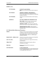
ODU-BUC (menu)
FSK COMMS
{NONE/CODAN/TERRASAT/AMPLUS}
(Only available when the FSK Comm is Enabled)
OFF/NONE:
Will disable the FSK Communication link. User must
select this option if the BUC does not support FSK or if
the customer does not want to utilize the FSK option.
TM138 – Rev. 1.0
4-7
User Interfaces
DMDVB20 LBST Satellite Modem
CODAN:
Enables the FSK Communication link for CODAN BUCs
only. This feature enables the DMD20LBST to retrieve
and display certain BUC parameters on the front panel
of the modem.
TERRASAT:
Enables the FSK communication link for Terrasat BUCs
only. This feature enables the DMD20LBST to retrieve
and display certain BUC parameters on the front panel
of the modem.
AMPLUS:
Enables the FSK communication link for AMPLUS
BUCs only. This feature enables the DMD20LBST to
retrieve and display certain BUC parameters on the front
panel of the modem.
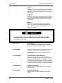
If user enables the FSK and the BUC does not support FSK, the modem
will display a fault or if the user selects the incorrect manufacturers BUC,
the unit will display a fault.
4-8
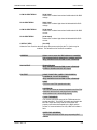
BUC OUTPUT
{Enable/Disable}
(Only available when the FSK Comm is Enabled)
Enables or Disables the BUC RF Output.
LO FREQ (MHz)
Allows the user to enter the Local Oscillator frequency of
the BUC LO in order for the uplink frequency to be
displayed correctly (refer to the BUC manufacturer’s
specifications).
OSC SIDE BAND
{LOW SIDEBAND, HIGH SIDEBAND}
Allows the user to select the location of the BUC LO.
The user must enter the location of the BUC LO in order
for the UPLINK FREQUENCY to be displayed correctly.
The BUC LO can be either higher or lower in frequency
than the BUC output frequency. If the BUC LO is higher
in frequency then the user must enter HIGH SIDEBAND.
10 MHz BUC REF
{ENABLED, DISABLED}
Allows the user to enable or disable the 10 MHz BUC
reference clock.
BUC VOLTAGE
{ENABLED, DISABLED}
Allows the user to enable or disable the BUC supply
voltage.
TM138 – Rev. 1.0
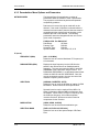
DMDVB20 LBST Satellite Modem
User Interfaces
LOW ALARM THRSH
{0.00 Volts}
Allows user to select lower alarm limit/threshold for BUC
voltage.
HI ALARM THRSH
{0.00 Volts}
Allows user to select high alarm limit/threshold for BUC
voltage.
LOW ALARM THRSH
{0.00 Amps}
Allows user to select lower alarm limit/threshold for BUC
current.
HI ALARM THRSH
{0.00 Amps}
Allows user to select high alarm limit/threshold for BUC
current.
CAR DLY (SEC)
{0 to 255}
Allows the user to select the time delay after power-up before the Tx Carrier may be
enabled. This allows time for the BUC to stabilize.
ADDRESS
Allows user to enter the BUC address to establish
FSK communications between the modem and BUC.
(Only available when the FSK Comm is Enabled)
BUC OUTPUT
{Enable/Disable}
(Only available when the FSK Comm is Enabled)
Enables or Disables the BUC RF Output.
FSK TEST
{NONE, PASSTHRU, QUERY FOR ADDRESS,
LOOPBACK, CYCLE TX ENABLE, }
(Only available when the FSK Comm is Enabled)
NONE:
This is the none FSK operational mode.
LOOPBACK:
The FSK will initiate an internal loopback test of the FSK
transmitter and receiver verifying that the modem
communication link is functioning properly.
CYCLE TX ENABLE:
The modem will initiate a test of the FSK between the
modem and BUC. The LBST will enable and disable the
BUC RF output and verify that the commands are
properly received and accepted by the BUC and the
modem. If communications are lost, LBST will initiate a
fault.
QUERY FOR ADDRESS:
The modem will initiate a FSK query requesting BUC
address.
TM138 – Rev. 1.0
4-9
User Interfaces
DMDVB20 LBST Satellite Modem
4.3.3 Demodulator Menu Options and Parameters
NETWORK SPEC
The Network Spec Command sets a number of
parameters within the modem to meet a specification.
The purpose is to eliminate keystrokes and potential
compatibility problems.
Data rates not covered by a given mode will not be
allowed. If the mode of operation is selected after the
data rate has been entered, then the data rate must be
compatible with the desired mode of operation or the
Network Spec will not be allowed. The following
parameters cannot be changed while the unit is in the
given mode of operation:
DVB-S2-CCM: Per EN 302 307
Data Rates:
All Rates
Framing Type:
DVB-S2
Scrambler Type:
DVB-S2
Spectrum Mask:
DVB 0.20, 0.25, 0.35
IF (menu)
FREQUENCY (MHz)
{950 – 2150 MHz}
Allows the user to enter the Modulator IF Frequency in 1
Hz increments.
DWNLNK FREQ (MHz)
Displays the input frequency into the LNB from the
satellite, also referred known as Satellite downlink
frequency. The user must enter the LNB LO and OSC
SIDEBAND of the LNB before using this menu. The
DOWNLINK FREQUENCY is a calculated measurement
of both the LNB LO and OSC SIDE BAND. Once the
menus are entered correctly, the user can control the
downlink Frequency from this menu.
SPECTRUM
{NORMAL, INVERTED, AUTO}
Allows the user to invert the direction of rotation for PSK
Modulation. Normal meets the IESS Specification.
Spectral inversion may be required if the LNB LO is
higher in frequency than the LNB input frequency from
the satellite. When LNB LO is higher in frequency than
the LNB input frequency, this creates a spectral
inversion and the IF Spectrum must be inverted to
compensate for the inversion.
4-10
MODULATION
{QPSK, 8PSK, 16APSK}
Allows the user to select the demodulation type.
SPECTRAL MASK
{DVB 0.35, DVB 0.25, DVB 0.20}
Allows the user to set the spectral shape of Rx Data
Filter.
TM138 – Rev. 1.0
DMDVB20 LBST Satellite Modem
User Interfaces
SWEEP RANGE (kHz)
{+/- 0.10 * Symbol Rate up to 7.5 MHz}
Allows the user to set the acquisition range for the
demodulator
INPUT LVL THRESH
{-30 to 90 dbm}
Allows the user to adjust the low level threshold limit for
input power. Input power level below the threshold limit
will trigger a major alarm on the demodulator.
EB/NO ALARM
{0.0 to 9.90 db}
Allows the user to set the desired Eb/No for the local
receiver. This setting is compared against the receive
Eb/No and commands to the remote modem to increase
or decrease Transmit Power accordingly are sent.
DATA (menu)
DATA RATE (bps)
{Refer to Technical Specs for Data Rates}
Allows the user to set the Data Rate in bps steps via the
Front Panel Arrows or Keypad.
SYMB RATE (sps)
Allows the user to view the Symbol Rate.
Maximum SR is 10 MSps
INNER FEC
DVB-S2:
Normal Block Size:
Viterbi {1/2, 3/5, 2/3, 3/4, 4/5, 5/6, 8/9, 9/10}
8PSK {3/5, 2/3, 3/4, 5/6, 8/9, 9/10}
16APSK {2/3, 3/4, 4/5, 5/6, 8/9, 9/10}
Short Block Size:
Viterbi {1/2, 3/5, 2/3, 3/4, 4/5, 5/6, 8/9}
8PSK {3/5, 2/3, 3/4, 5/6, 8/9}
16APSK {2/3, 3/4, 4/5, 5/6, 8/9}
Allows the user to select the Rx Code Rate and Type
SAT FRAMING
{DVB-S2 NORMAL, DVB-S2 SHORT}
Allows the user to select the LDPC decoder frame size.
Default is DVB-S2 NORMAL.
TERR FRAMING
{NONE, 188, 204}, when using DVB Network Spec
DATA POLARITY
{ NONE, INV. BASEBAND, INV.TERR DATA, INV.
TERR & BASE,}
Allows the user to invert the Rx Data polarity.
PILOT SYMBOLS
{DISABLED, ENABLED}
Allows the user to turn on or off pilot symbol insertion.
Default is off.
TM138 – Rev. 1.0
4-11
User Interfaces
GOLD SEQ N
DMDVB20 LBST Satellite Modem
{000000}
Allows the user to enter specific tap value to choose
different gold sequences for the S2 scrambler. The unit
are decimal and the maximum value allow is 218 -1.
ODU-LNB (menu)
LO FREQ (MHz)
Allows the user to enter the LNB Local Oscillator
frequency in MHz in order for the downlink frequency to
be displayed correctly (refer to the LNB manufacturer’s
specifications).
OSC SIDE BAND
{LOW SIDEBAND, HIGH SIDEBAND}
Allows the user to select the location of the LNB LO.
The user must enter the location of the LNB LO in order
for the DOWNLINK FREQUENCY to be displayed
correctly. The LNB LO can be either higher or lower in
frequency than the LNB output frequency. If the LNB LO
is higher in frequency then the user must enter HIGH
SIDEBAND.
10 MHz LNB REF
{ENABLED, DISABLED}
Allows the user to enable or disable the 10 MHz BUC
reference clock.
VOLTAGE SELECT
{13, 15, 18, 20}
Allows the user to select the voltage required by the LNB
(refer to the LNB manufacturer’s specifications)
LNB VOLTAGE
{ENABLED, DISABLED}
Allows the user to enable or disable the LNB supply
voltage.
4.3.4 Interface Menu Options and Parameters
TX SETUP (menu)
CIRCUIT ID
Allows the user entry of a Tx Circuit Identifier. Circuits
can be given up to an 11 Character alphanumeric
identity such as LINK1.
TERR INTERFACE
STANDARD INTERFACE
{RS422 SERIAL,RS232 SERIAL, V.35}
Allows the user to select the Transmit Interface Type.
4-12
TX CLK SRC
{SCTE, SCT, EXT CLK}
Allows the user to select the Transmit Clock Source.
TX CLK POL
{AUTO, NORMAL, INVERTED}
Allows the user to select the Clock Polarity for the Tx
Terrestrial Clock relative to the Tx Data. “Auto” detects
wrong polarity and automatically corrects. If G.703
Interface is selected, this selection cannot be changed.
TM138 – Rev. 1.0
DMDVB20 LBST Satellite Modem
SCT CLK SRC
User Interfaces
{INTERNAL, SCR}
Allows the user to select internal Source. SCT is the
internally generated SCT clock. SCR is the Rx Satellite
clock. SCR is used for loop timing.
RX SETUP (menu)
CIRCUIT ID
Allows the user entry of a Tx Circuit Identifier. Circuits
can be given up to an 11 Character alphanumeric
identity such as LINK1.
TERR INTERFACE
STANDARD INTERFACE
{RS422 SERIAL,RS232 SERIAL, V.35}
Allows the user to select the Transmit Interface Type.
BUFF SIZE (msec)
{0 - 64 msecs}
Allows the user to set the Doppler Buffer Size in msec.
BUFFER CLK SRC
Note: RX Sat only supported in Version A
The user must assign priorities to the clock sources. 1
being the highest priority and 4 being the last resort.
The menu has three fields; the first field is the name of
the clock source, the second field is the priority entry
area, and the last field is the depth of the list. In the
priority field, the up/down arrow keys will scroll through
the list displaying the names and the current priority.
When the desired clock name is displayed, the number
keys may be used to assign a priority value. Pressing
<Enter> will re-sort the list. Do this until the clock
sources are prioritized in the order desired. Use the
left/right arrow keys to move the cursor to the depth field.
This field assigns the number of entries to use. The
number keypad or the up/down arrows can be used to
change the value.
Clock Source
RX SAT
SCTE
SCT
EXT BNC
Priority
1
2
3
4
SRC DEPTH
of
of
of
of
3
3
3
3
Only these will
be used
Will not be
used since
4>3
BUFFER CLK POL
{NORMAL, INVERTED}
Allows the user to select the Clock Polarity for the Rx
Terrestrial Clock relative to the Rx Data.
TERR STREAMING
{BYTE OUTPUT}
TM138 – Rev. 1.0
4-13
User Interfaces
DMDVB20 LBST Satellite Modem
GENERAL (menu)
EXT FREQ (MHz)
{Variable Through Data Rate}
Allows the user to select the external clock frequency in
MHz.
REF FREQ SRC
{INTERNAL, EXTERNAL, HIGH STABILITY}
Allows the user to select the Frequency Reference
Source. High Stability is only displayed if the appropriate
hardware is detected.
REF FREQ (MHz)
Allows the user to select the reference clock frequency
in MHz.
BB RELAYS
{IBS ALMS, IBS/MNR/ALMS, IBS/MNR/MJR ALM}
IBS ALARMS: Allows the user to select rear panel
contact closures to support IBS alarms only.
IBS/MINOR ALARMS: Allows the user to select rear
panel contact closures to support IBS and Minor alarms.
IBS/MINOR/MAJOR ALARMS: Allows the user to
select rear panel contact closures to support IBS, Minor
and Major alarms.
4.3.5 Monitor Menu Options and Parameters
EVENTS
Displays a history of events recorded in the event buffer.
A maximum of 100 events may be stored in the buffer.
Upon receipt of the 101st event, the first received event
is automatically deleted, and so on, maintaining the
maximum 100 events.
ERASE EVENTS.. PRESS CLEAR
Allows the user to clear the contents of the Event Buffer
by pressing <CLEAR> on the keypad.
INPUT LVL (dBm)
Displays the estimated receive signal level as seen by
the Demodulator.
FREQ OFFSET
Displays the received carrier frequency offset as
measured by the modem.
EBNO (dB)
Displays the estimated Eb/No as seen by the
demodulator.
PKT ERROR RATE
{0.00E-00} NEEDS INFO
This screen displays the ratio of mpeg packets with CRC
errors to mpeg packets with no errors. No CRC errors =
0, every packet with a CRC error = 1.
4-14
TM138 – Rev. 1.0
DMDVB20 LBST Satellite Modem
User Interfaces
VOLTAGES (menu)
+1.5V RX SUPPLY
Displays the measured voltage of the 1.5 Volt Rx power
bus located inside the modem.
+1.5V TX SUPPLY
Displays the measured voltage of the 1.5 Volt Tx power
bus located inside the modem.
+3.3V SUPPLY
Displays the measured voltage of the +3.3 Volt power
bus located inside the modem.
+5V SUPPLY
Displays the measured voltage of the +5 Volt power bus
located inside the modem.
+12V SUPPLY
Displays the measured voltage of the +12 Volt power
bus located inside the modem.
+20V SUPPLY
Displays the measured voltage of the +20 Volt power
bus located inside the modem.
-12V SUPPLY
Displays the measured voltage of the -12 Volt power bus
located inside the modem.
BUC CURRENT
Displays the measured current of the BUC.
BUC VOLTAGE
Displays the measured voltage of the BUC.
ODU-BUC (menu)
POWER OUT (dBm)
Displays the measured output power of the BUC in dBm.
Only displayed with Smart BUCs that support this
feature in FSK mode.
TEMPERATURE
Displays the measured temperature of the BUC in
degrees Celsius. Only displayed with Smart BUCs that
support this feature in FSK mode.
BUC SUMMARY
Displays a summary status of the BUC. Only displayed
with Smart BUCs that support this feature in FSK mode.
RX BUFFER LEVEL
{0 – 100%}
Displays the status of the Doppler Buffer.
RX BUFFER RESET ((ENTER)) Allows the user to re-center the Doppler Buffer when
<ENTER> is pressed on the keypad.
TM138 – Rev. 1.0
4-15
User Interfaces
DMDVB20 LBST Satellite Modem
4.3.6 Alarms Menu Options and Parameters
Masking alarms may cause undesirable modem performance.
CURRENT ALARMS (menu)
TX MAJOR (menu)
4-16
Status
Edit Table
FPGA CFG
{Pass/Fail, Unmasked/Masked}
Indicates a transmit FPGA configuration failure.
DSP CFG
{Pass/Fail, Unmasked/Masked}
Indicates a transmit DSP configuration failure.
SCT CLOCK PLL
{Pass/Fail, Unmasked/Masked}
Indicates that the Tx SCT Clock PLL is not locked. This
alarm will flash on during certain modem parameter
changes. A solid indication points toward a configuration
failure within the modem.
SYM CLOCK PLL
{Pass/Fail, Unmasked/Masked}
Indicates that the Tx Symbol Clock PLL is not locked.
This alarm will flash on during certain modem parameter
changes. A solid indication points toward a problem with
the incoming clock to the modem (SCTE).
LB SYNTH PLL
{Pass/Fail, Unmasked/Masked}
Indicates that the Tx L-Band Synthesizer is not locked.
This alarm will flash on during certain modem parameter
changes. A solid indication points toward a configuration
problem within the modem.
BUC CURRENT
{Pass/Fail, Unmasked/Masked}
Indicates that the BUC current has fallen outside of the
threshold limits.
BUC VOLTAGE
{Pass/Fail, Unmasked/Masked}
Indicates that the BUC voltage has fallen outside of the
threshold limits.
FORCED ALARM
{DISABLED, ENABLED}
Allows user to disable or enable forcing of a Tx
Summary Alarm.
TM138 – Rev. 1.0
DMDVB20 LBST Satellite Modem
User Interfaces
TX MINOR (menu)
TERR CLK ACT
{Pass/Fail, Unmasked/Masked}
Indicates no Terrestrial Clock activity.
TERR DATA ACT
{Pass/Fail, Unmasked/Masked}
Indicates no Tx Data activity.
TX TERR AIS
{Pass/Fail, Unmasked/Masked}
Indicates that AIS has been detected in the Tx Data
Stream.
DnI FRAME LOCK
{Pass/Fail, Unmasked/Masked}
Indicates the framing unit is unable to find the expected
terrestrial framing pattern.
DnI M-FRAME LOCK
{Pass/Fail, Unmasked/Masked}
Indicates the framing unit is unable to find the expected
inter-frame pattern.
TX DVB FRM LOCK
{Pass/Fail, Unmasked/Masked}
Indicates that Tx input data stream framing does not
match the user selected TX TERR FRAMING.
TX CLK SRC FALLBK {Pass/Fail, Unmasked/Masked}
Indicates that the clock resource has fallen.
BUC PLL
{Pass/Fail, Unmasked/Masked}
Indicates that the BUC has a PLL fault. Only available
when used with Smart BUC that support this FSK option.
BUC OVER TEMP
{Pass/Fail, Unmasked/Masked}
Indicates that the BUC has an over temperature fault.
Only available when used with Smart BUC that support
this FSK option.
BUC SUMMARY
{Pass/Fail, Unmasked/Masked}
Indicates that the BUC has a Summary fault. Only
available when used with Smart BUC that support this
FSK option.
BUC OUTPUT
{Pass/Fail, Unmasked/Masked}
Indicates BUC PLL has failed. (Only available when FSK
is enabled)
FSK COMMS
{Pass/Fail, Unmasked/Masked}
Indicates that the modem has lost communications with
the BUC
RX MAJOR (menu)
FPGA CFG
{Pass/Fail, Unmasked/Masked}
Indicates a receive FPGA hardware failure.
DSP CFG
{Pass/Fail, Unmasked/Masked}
Indicates a receive DSP failure.
TM138 – Rev. 1.0
4-17
User Interfaces
DMDVB20 LBST Satellite Modem
DM CFG
{Pass/Fail, Unmasked/Masked}
Indicates a demodulator DVB-S/DVB-S2 FPGA
hardware failure.
SIGNAL LOCK
{Pass/Fail, Unmasked/Masked}
Indicates that the demod is unable to lock to a signal.
INPUT LVL THRESH
{Pass/Fail, Unmasked/Masked}
Indicates Rx signal level has fallen below input
threshold.
FRAME LOCK
{Pass/Fail, Unmasked/Masked}
Indicates that the Framing Unit is unable to find the
expected framing pattern.
LB SYNTH PLL
{Pass/Fail, Unmasked/Masked}
Indicates that the Rx L-Band Synthesizer is not locked.
This alarm will flash on during certain modem parameter
changes. A solid indication points toward a configuration
problem within the modem.
FORCED ALARM
{DISABLED, ENABLED}
Allows user to enable a forced Rx summary alarm.
RX MINOR (menu)
BUFF UNDERFLOW
{Pass/Fail, Unmasked/Masked}
Indicates that a Doppler Buffer underflow has occurred.
BUFF NEAR EMPTY
{Pass/Fail, Unmasked/Masked}
Indicates that the Doppler Buffer is about to underflow.
BUFF NEAR FULL
{Pass/Fail, Unmasked/Masked}
Indicates that the Doppler Buffer is about to overflow.
BUFF OVERFLOW
{Pass/Fail, Unmasked/Masked}
Indicates that a Doppler Buffer overflow has occurred.
RX DATA ACTIVITY
{Pass/Fail, Unmasked/Masked}
Indicates that there is no Rx Data activity.
IFEC LOCK
{Pass/Fail, Unmasked/Masked}
Indicates that the Framing Unit is unable to find the
expected framing pattern.
EBNO (dB)
{Pass/Fail, Unmasked/Masked}
Indicates that the Eb/No are outside of limits.
COMMON (menu)
4-18
TERR FPGA CFG
{Pass/Fail, Unmasked/Masked}
Indicates an Interface Card FPGA configuration failure.
CODEC FPGA CFG
{Pass/Fail, Unmasked/Masked}
Indicates Turbo Codec Card FPGA configuration failure.
TM138 – Rev. 1.0
DMDVB20 LBST Satellite Modem
User Interfaces
CODEC DEV CFG
{Pass/Fail, Unmasked/Masked}
Indicates Turbo Codec Card ASIC configuration failure.
EXT CLOCK ACT
{Pass/Fail, Unmasked/Masked}
Indicates the External Clock activity.
EXT REF ACT
{Pass/Fail, Unmasked/Masked}
Indicates the External Reference activity.
EXT REF LOCK
{Pass/Fail, Unmasked/Masked}
Indicates the External Reference PLL is locked
detection.
VOLTAGES (menu)
+1.5V RX SUPPLY {Pass/Fail, Unmasked/Masked}
Displays the measured voltage of the 1.5 Volt Rx power
bus located inside the modem.
+1.5V TX SUPPLY {Pass/Fail, Unmasked/Masked}
Displays the measured voltage of the 1.5 Volt Tx power
bus located inside the modem.
+3.3V SUPPLY
{Pass/Fail, Unmasked/Masked}
Displays the measured voltage of the +3.3 Volt power
bus located inside the modem.
+5V SUPPLY
{Pass/Fail, Unmasked/Masked}
Displays the measured voltage of the +5 Volt power bus
located inside the modem.
+12V SUPPLY
{Pass/Fail, Unmasked/Masked}
Displays the measured voltage of the +12 Volt power
bus located inside the modem.
+20V SUPPLY
{Pass/Fail, Unmasked/Masked}
Displays the measured voltage of the +20 Volt power
bus located inside the modem.
-12V SUPPLY
TM138 – Rev. 1.0
{Pass/Fail, Unmasked/Masked}
Displays the measured voltage of the -20 Volt power bus
located inside the modem.
4-19
User Interfaces
DMDVB20 LBST Satellite Modem
LATCHED ALARMS
{Pass/Fail}
The following alarms are latched in order to catch
intermittent failures:
TX MAJOR (menu)
FPGA CFG
DSP CFG
SCT CLOCK PLL
SYM CLOCK PLL
LB SYNTH PLL
BUC CURRENT
BUC VOLTAGE
TX MINOR (menu)
TERR CLK ACT
TERR DATA ACT
TX TERR AIS
DnI FRAME LOCK
DnI M-FRAME LOCK
TX DVB FRM LOCK
TX CLKSRC FALLBK
BUC PLL
BUC OVER TEMP
BUC SUMMARY
BUC OUTPUT
FSK COMMS
RX MAJOR (menu)
FPGA CFG
DSP CFG
DMD CFG
SIGNAL LOCK
4-20
TM138 – Rev. 1.0
DMDVB20 LBST Satellite Modem
User Interfaces
INPUT LVL THRESH
FRAME LOCK
LB SYNTH PLL
RX MINOR (menu)
BUFF UNDERFLOW
BUFF NEAR EMPTY
BUFF NEAR FULL
BUFF OVERFLOW
RX DATA ACTIVITY
EBNO
COMMON (menu)
TERR FPGA CFG
CODEC FPGA CFG
CODEC DEV CFG
EXT CLOCK ACT
EXT REF ACT
EXT REF LOCK
VOLTAGE (menu)
+1.5V RX SUPPLY
+1.5V TX SUPPLY
+3.3V SUPPLY
+5V SUPPLY
+12V SUPPLY
-12V SUPPLY
+20V SUPPLY
CLEAR LATCHED ((ENTER)) Allows the user to reset the latched alarms by pressing
<ENTER> on the keypad.
TM138 – Rev. 1.0
4-21
User Interfaces
DMDVB20 LBST Satellite Modem
4.3.7 System Menu Options and Parameters
DATE (MM/DD/YY)
Allows the user to enter the current date.
TIME {HH:MM:SS}
Allows the user to enter the current time.
CONFIG COPY
{Current, CFG1……CFG10}
Allows user to copy, save and recall modem
configurations.
FRONT PANEL (menu)
BKLT LEVEL
{OFF, LOW, MED, HIGH}
Allows the user to enter the backlight intensity level.
BKLT TIMEOUT
{00 - 99}
Allows the user to enter the length of time (in seconds)
of keyboard inactivity before the backlight shuts off. 00
= no timeout.
KEY CLICK
{ON, OFF}
Allows the user to enable or disable the audible beep
each time a key is pressed. Illegal entries will still cause
a beep to be heard.
MENU NAVIGATION
{STANDARD, FLOATING}
Standard: This setting has a fixed starting point for all
sub-menus.
Floating: Sub-menus are floating, always returning to
the last menu that was accessed.
LED TEST
{ENTER}
Allows user to test all front panel LEDs.
REMOTE CONTROL
{TERMINAL, COMPUTER}
Allows the user to select between terminal RS-232
control and remote port M&C RS-232/-485 control.
TERMINAL (menu)
4-22
TYPE
{VT-100, WYSE50, VIEWPOINT}
Allows the user to select the emulation type.
BAUD RATE
{300, 600, 1200, 2400, 4800, 9600, 19200, 38400,
57600}
Allows the user to enter the terminal baud rate.
TM138 – Rev. 1.0
DMDVB20 LBST Satellite Modem
User Interfaces
REMOTE PORT (menu)
ADDRESS
{32 - 255}
Allows the user to enter the Remote Port Multidrop
Address.
BAUD RATE
{300, 600, 1200, 2400, 4800, 9600, 19200, 38400,
57600}
Allows the user to enter the Remote Port Baud Rate.
INTERFACE
{RS-232, RS-485}
Allows the user to enter the Remote Port interface type.
TCP/IP Menu (THIS FEATURE IS NOT SUPPORTED)
BOOT MODE
{DEFAULT, NON-VOL, BOOTP, IP TEST}
DEFAULT: During initialization (boot up), the modem will restore the
web setting to the standard IP Mask and addresses supplied by the
modem. The modem will be taken off the network and will not be
accessible. The Default settings are:
IP Address Mask:
Modem IP Address:
Server IP Address:
Router IP Address:
BOOTP:
255.000.000.000
010.000.000.001
010.001.001.001
010.000.001.001
(FF.00.00.00 hex)
(C0.A8.00.EE hex)
(0A.01.01.01 hex)
(0A.00.01.01 hex)
During initialization (boot up), the modem will get the
names, masks, and IP Addresses of the modem, router,
and server.
NON-VOL: Stores and uses IP Mask and addresses as provided by
the user.
IP TEST: Stores and uses IP Mask and addresses to fixed settings as
listed below.
Bootp Server Tag:
IP Address Mask:
Modem IP Address:
Server IP Address:
Router IP Address:
206
255.255.255.000
192.168.0.238
192.168.000.101
192.168.000.102
(FF.FF.FF.00 hex)
(C0.A8.00.EE)
(C0.A8.00.65)
(C0.A8.00.66)
BOOTp SERVER
{128 – 257, default is 206}
Only used if Bootp is selected in Boot Mode. Should be
consistent with the tag expected by the users Bootp
Server.
MODEM HOST The Host Modem for the network.
IP ADDR MASK
TM138 – Rev. 1.0
{XXX.XXX.XXX.XXX} Hexadecimal Mask
{ddd.ddd.ddd.ddd} Decimal Mask
4-23
User Interfaces
DMDVB20 LBST Satellite Modem
The IP Address Mask of the local network. The mask is
expressed in a hexadecimal format, and must be a valid
TCP/IP Mask. This field should be set before changes
are made to the Modem or Router Address.
MODEM IP ADDR
{XXX.XXX.XXX.XXX} Hexadecimal Address
{ddd.ddd.ddd.ddd} Decimal Mask
The IP Address of the modem. This address should be
consistent for the mask defined. This address is
expressed in hexadecimal format. Broadcast and loop
back addresses will not be allowed. These are
addresses with all subnet bits set to 0’s or 1’s.
ROUTER IP ADDR
{XXX.XXX.XXX.XXX} Hexadecimal Address
{ddd.ddd.ddd.ddd} Decimal Address
The IP Address of the Local Network Router. If a router
is present on the local network, this address must be
consistent with the IP Mask and the subnet of the
modem. If no router is present, then the address should
be set to a foreign address. This address is expressed
in hexadecimal format.
BOOTP SERVER
{XXX.XXX.XXX.XXX} Hexadecimal Address
{ddd.ddd.ddd.ddd} Decimal Address
The IP Address of the Boot Server and the address of
the SNMP Trap Server when SNMP is active. If a server
is used and there is no local router, this address must be
consistent with the modem address. If a router has been
specified, the address is presumed to be reachable via
the router. Broadcast and loop back addresses will not
be allowed. These are addresses with all subnet bits set
to 0’s or 1’s.
Broadcast and loop back addresses will not be allowed.
These are addresses with all subnet bits set to 0’s or 1’s.
To change the display for the IP ADDRESS MASK, MODEM IP ADDRESS,
SERVER IP ADDRESS, AND ROUTER IP ADDRESS, press all four arrow
keys simultaneously.
4-24
MODEM EADDR
{001065010000}
Displays the Ethernet address of the device. Set at the
factory and is a unique identifier for the Ethernet physical
interface.
ETHER RATE
{10 MBPS/HD}
The data rate for the local Ethernet Interface.
TM138 – Rev. 1.0
DMDVB20 LBST Satellite Modem
User Interfaces
10 Mbps/HD – for 10 Base-T in either half-duplex or full
duplex.
HW/FW CONFIG (menu)
FIRMWARE REV
Displays the installed firmware revision.
M&C REV
Displays the installed Monitor and Control revision.
MAIN BOARD (menu)
Only the appropriate of the VCO adjustment screens listed below will be
displayed. These are protected fields, to prohibit accidental changes. To
edit the field, the user must depress all four of the direction arrow keys
simultaneously.
INT VCO ADJUST
{0% - 100%}
Allows the user to adjust the internal frequency
reference for calibration. Only displayed of the system
reference clock is INTERNAL.
HI STAB VCO ADJUST {0% - 100%}
Allows the user to adjust the internal frequency
reference for calibration. Only displayed if the system
reference clock source is HI STABILITY.
LARGEST HB GAP
Used for factory test only.
SOFT RESET
{Enter}
IF BOARD (menu)
Indicates the Radyne
Assembly.
part number for the IF Board
AGC/CTRL/VALUE
{0% - 100%}
Allows the user to adjust the internal frequency
reference for calibration. Only displayed if the system
reference clock source is HI STABILITY.
I OFFSET
Used for factory test only.
Q OFFSET
Used for factory test only.
LB RX LVL OFFSET
Used for factory test only.
POWER SOURCE
Used for factory test only.
TM138 – Rev. 1.0
4-25
User Interfaces
DMDVB20 LBST Satellite Modem
TERR INTFC BRD
Indicates the Radyne assembly number for the
Terrestrial Interface Assembly.
CODEC BOARD (menu)
Indicates the Radyne part number for the Codec Board.
TPC FPGA IMAGE
Used for factory test only.
RS FPGA IMAGE
Used for factory test only.
TPC CODEC IMAGE
Used for factory test only.
FRONT PANEL BOARD
Indicates the Radyne assembly number for the front
panel board.
FEATURES (menu)
5012.2840.2417
{____.____.____}
Allows the user to install purchased feature upgrades
(see Appendix A).
Contact the Radyne Customer Service Department or
Sales for hardware and software upgrades.
UPGRADE LIST (menu) The following identifies the available upgrade features:
10 MBPS, 20 MBPS (The highest option installed will hide the lower
rates.)
RXLBAND
TXLBAND
IDR
(TX only)
SEQ
(TX only)
RS
RS CUSTOM
(TX only)
IBS
(TX only)
8PSK
16QAM
TURBO 20 MBPS
(TX only)
DVB
4-26
TM138 – Rev. 1.0
DMDVB20 LBST Satellite Modem
User Interfaces
4.3.8 Test Menu Options and Parameters
TX TEST PATTERN
{NONE, 2047, 2^15-1, 2^23-1}
Allows the user to enable the tests listed above.
RX TEST PATTERN
{NONE, 2047, 2^15-1, 2^23-1}
Allows the user to enable the tests listed above.
PATTERN SYNC
{YES, NO}
Yes indicates that the RX Test Pattern is in sync.
TST PAT ERR CNT
{NO SYNC, nnnn x 10n}
Displays the number of errors detected by the test
pattern checker.
TST PATT BER
{NO SYNC, nnnn x 10-n}
Displays the measured BER for the test pattern.
RESTART TST PAT ((ENTER))
Allows the user to restart the test by pressing <ENTER>
on the keypad.
LOOPBACK WITH ETHERNET DATA INTERFACE
Usage of the modems loopback capabilities in conjunction with the Ethernet data
interface can produce undesirable network loops. In order to run any type of data test
with an Ethernet interface you must utilize two modems connected back to back. Simply
using one modem and a loopback will not produce the desired results.
LOOPBACK
{NONE, TERR TX, BASEBAND TX, IFEC TX}
Terrestrial Loopback is performed at the Terrestrial
Interface
NONE: No loopback performed.
TERR TX: Sends Tx Terrestrial Data to Rx data out.
BASEBAND TX: Sends Tx data to the receive input to
the BB Card.
CARRIER TYPE
{NORMAL, CW, DUAL, OFFSET, POS FIR, NEG FIR}
Allows the user to set the type of carrier.
NORMAL: Causes the Modulator to output normal
modulation.
CW: Causes the Modulator to output a pure carrier.
DUAL: Causes a double sideband output.
TM138 – Rev. 1.0
4-27
User Interfaces
DMDVB20 LBST Satellite Modem
OFFSET: Causes a single sideband output.
POS FIR: For manufacturer’s use only.
NEG FIR: For manufacturer’s use only.
4-28
TM138 – Rev. 1.0
DMDVB20 LBST Satellite Modem
User Interfaces
4.4 Terminal Mode Control
The Terminal Mode Control allows the use of an external terminal or computer to monitor and
control the modem from a full screen interactive presentation operated by the modem itself. No
external software is required other than VT-100 Terminal Emulation Software (e.g. “Procomm”
for a computer when used as a terminal. The Control Port is normally used as an RS–232
Connection to the terminal device. The RS-232 operating parameters can be set using the
modem Front Panel and stored in EEPROM for future use.
Refer to the DMDVB20 LBST Remote Protocol Manual (TM137) for the
terminal screens.
4.4.1 Modem Terminal Mode Control
The modem can be interactively monitored and controlled in the Terminal Mode, with a full screen
presentation of current settings and status.
The Terminal Control Mode supports several baud rates, however the connection must be set for
8 data bits, 1 stop bit and no parity (8,N,1). Three terminal emulations are supported: VT-100,
WYSE 50, and ADDS-VP.
“$” is used for setting the screen when the terminal is used for the first time the non-volatile
memory is reset.
4.4.2 Modem Setup for Terminal Mode
Terminal Mode Communications and Protocol is set from the Front Panel Control by setting the
“Control Mode” Parameter to “Terminal”, and then setting the “Modem Port”, “Term Baud” and
“Emulation” Parameters as desired. Then a terminal is connected to Connector J20 on the Back
Panel. All operating software for the Terminal Mode is contained within the Modem Internal
Control Software.
A “break” signal on the communications line, pressing “ESC” on the terminal or Power On of the
modem will initiate full screen terminal mode printing and redraw the full screen. The Terminal
Mode displays the present status of all user parameters controlled and read by the processor,
and offers a menu allowing change to any controlled parameter.
The Terminal Mode uses eight “Screens,” each of which have the basic contents of the three
modem monitor and control areas as set in the Front Panel matrix columns. This screen is used
for setting the parameters of the Modulator, Demodulator, Event, Alarm, Latched Alarm, Drop
Controls, Insert Controls, and Interface Areas.
TM138 – Rev. 1.0
4-29
User Interfaces
DMDVB20 LBST Satellite Modem
4.5 Terminal Port User Interface
The Remote Port (J20) of the modem allows for complete control and monitoring of all
parameters and functions via an RS-232 Serial Interface, or RS-485 for RLLP Protocol. ‘Terminal
Mode’ can be entered from the front panel by selecting “System” and then “Control Mode”
followed by “Terminal”. The baud rate and evaluation type can be changed at the front panel by
using the System>Baud Rate Menu.
The Terminal Control Mode is menu-driven and the allowable values for each item number will be
shown. To change an item, type in its number followed by <ENTER>. If the parameter to be
changed requires a numeric value, enter the number followed by <ENTER> If the parameter is
non-numeric, press <SPACE> to cycle through the list of available entries.
Items that do not have ID numbers are Status only and cannot be
changed.
4.6 Connecting the Terminal
1.
Connect the computer to the Remote Connector (J20) on the rear of the unit
using the RS-232 Cable.
2.
Enable the terminal by selecting Terminal Mode (located under the System Control Mode Menu) from the front panel.
3.
Verify that your emulation software is set to the following:
8 data bits
no parity
1 stop bit
Modify the selection, if necessary, to match the settings (the Front Panel
‘SYSTEM’ Sub-Menu contains all the Terminal Emulation Controls).
4.7 Terminal Screens
Refer to the DMDVB20 LBST Remote Protocol Manual (TM137) for the
terminal screens.
4-30
TM138 – Rev. 1.0
DMDVB20 LBST Satellite Modem
TM138 – Rev. 1.0
User Interfaces
4-31
DMDVB20 LBST Satellite Modem
Rear Panel Interfaces
Rear Panel Interfaces
5
This section discusses the electrical interfaces available from the rear panel. All locations are as
viewed from the rear of the unit unless otherwise specified.
5.0 DMDVB20 LBST Connections
All DMDVB20 LBST connections are made to labeled connectors located on the rear of the unit
(refer to Figure 5-1 for the DMDVB20 LBST. The connector definitions below are those on the
DMDVB20 LBST unit. Any connection interfacing to the DMDVB20 LBST must be the
appropriate mating connector.
Figure 5-1. DMDVB20 LBST Satellite Modem Rear Panel Configurations
5.1 Compact Flash
The compact flash slot is located on the right side as viewed from the rear of the unit. A 128 or
256 Mbit flash memory card that stores all the modem M&C and operational data. It must be
present when the modem is operating.
TM138 – Rev. 1.0
5-1
Rear Panel Interfaces
DMDVB20 LBST Satellite Modem
5.2 Power Input Modules
5.2.1 AC Power Input Module
AC Input Module (Figure 5-1) is located on the left side of the unit. Power applied to the port with
the supplied power cable is 100 – 240 VAC, 50 – 60 Hz. Integrated into the Power Input Module
is the Power On/Off Rocker Switch. Power consumption for the unit is 1A. A chassis ground
connection (#10-32 threaded stud), is located to the lower right of the module .5.2.2 DC Power
Input/Switch
The Optional DC Power Input and Switch (Figure 5-1) is available for all DMDVB20 LBST
products. The unit may be powered from a 36 – 75 VDC source with a maximum unit power
consumption of 3 A. Refer to Table 5-1 for pinouts.
Table 5-1. DC Power
A
–
B
Ground
C
+
5.3 DMDVB20 LBST Chassis Connections
5.3.1 EXT REF (J10)
The External Reference Port is a 50-Ohm Female BNC Connector and will accept the following
frequencies: 1.0, 1.544, 2.0, 2.048, 5.0, and 10.0 MHz.
5.3.2 TX L-Band IF (J11)
The Transmit Output Port is a 50-Ohm Type-N Connector. The power level is programmable
from 0 to -25 dBm, in 0.1 dBm steps. The IF Frequency can be programmed to 950 – 2050 MHz,
in 1 Hz Steps.
5.3.3 RX (J1)
The Receive Input Port is a 75-Ohm F-Type Connector. The IF Frequency can be programmed
from 950 to 2150 MHz in 1 Hz Steps.
5.3.4 ALARM (J15)
The Alarm Port is a 15-Pin Female “D” Connector. Refer to Table 5-2 for pinouts.
Table 5-2. ALARM Port 15-Pin Female “D” Connector (J15)
Pin No.
5-2
Signal Name
Signal
Direction
1
Mod Fault
MF-C
No Direction
2
Mod Fault
MF-NC
No Direction
3
Mod Fault
MF-NO
No Direction
4
Demod Fault
DF-C
No Direction
TM138 – Rev. 1.0
DMDVB20 LBST Satellite Modem
Rear Panel Interfaces
5
Demod Fault
DF-NC
No Direction
6
Demod Fault
DF-NO
No Direction
*7
Prompt
CEF-C
No Direction
*8
Prompt
CEF-NC
No Direction
*9
Prompt
CEF-NO
No Direction
*10
Service
SP1-C
No Direction
*11
Service
SP1-NC
No Direction
*12
Service
SP2-NO
No Direction
13
No Connection
SP2-NC
No Direction
14
AGC Out
AGC
No Direction
15
Ground
GND
---
Note: Normally open or Normally closed conditions identified above indicate a faulted stated or
off condition.
*Note: Pins 1 through 6 offers form C contacts for Major Alarm Status on the Modulator and
Demodulator. When the modem is configured for IBS Network Specification, pins 7-9 only
support the IBS Prompt Alarms and pins 10-12 only support IBS Service Alarms. If the Network
specification is configured for Closed Net, the contact closures for Prompt and Service can be
utilized to include the summary of all minor alarms or minor/major alarms. The IBS Prompt
menus can include TX Minor Alarms or TX Minor Alarm and TX Major Alarms. The IBS Service
Alarms can include RX Minor Alarms or RX Minor Alarms and RX Major Alarms.
5.3.5 EXT CLK (J16)
The External Clock Port is a 75-Ohm Female BNC Connector. It allows interfacing to an external
clock source.
5.3.6 ASYNC (J17) (NOT SUPPORTED)
5.3.7 (J18)
Radyne factory use only.
TM138 – Rev. 1.0
5-3
Rear Panel Interfaces
DMDVB20 LBST Satellite Modem
5.3.8 EIA-530 (J19)
The EIA-530 Port is an RS-422/V.35/RS-232 Connection. It is a 25-Pin Female “D” Connector.
Refer to Table 5-3 for pinouts.
Table 5-3. EIA-530 Port (RS-422/V.35/RS-232) 25-Pin Female “D” Connector (J19)
Pin No.
5-4
Signal Name
Signal
Direction
---
---
1
Shield
2
Send Data A (-)
SD-A
Input
3
Receive Data A (-)
RD-A
Output
4
Request To Send A (-)
RS-A
Input
5
Clear To Send A (-)
CS-A
Output
6
Data Mode A (-)
DM-A
Output
7
Signal Ground
SGND
---
8
Receiver Ready A (-)
RR-A
Output
9
Receive Timing B (+)
RT-B
Output
10
Receiver Ready B (+)
RR-B
Output
11
Terminal Timing B (+)
TT-B
Input
12
Send Timing B (+)
ST-B
Output
13
Clear T Send B (+)
CS-B
Output
14
Send Data B (+)
SD-B
Input
15
Send Timing A (-)
ST-A
Output
16
Receive Data B (+)
RD-B
Output
17
Receive Timing A (-)
RT-A
Output
18
Modulator Fault - Open Collector
MF
Output
19
Request To Send B (+)
RS-B
Input
20
Data Terminal Ready A (-)
TR-A
Input
21
Demodulator Fault
DF
Output
22
Data Mode B (+)
DM-B
Output
23
Data Terminal Ready B (+)
TR-B
Input
24
Terminal Timing A (-)
TT-A
Input
25
No Connection
---
---
TM138 – Rev. 1.0
DMDVB20 LBST Satellite Modem
Rear Panel Interfaces
5.3.9 REMOTE (J20)
The Remote Port is a RS-485 or RS-232 Connection for remote monitor and control of the
modem. It is a 9-Pin Female “D” Connector. Refer to Table 5-4 for pinouts.
Table 5-4. Remote Port (RS-485 or RS-232) 9-Pin Female “D” Connector (J20)
Pin No.
Signal Name
Signal
Direction
1
Transmit Data RS-485 (+)
TX-485-B
Output
2
Transmit Data RS-232
TXD-232
Output
3
Receive Data RS-232
RXD-232
Input
4
NC
NC
---
5
Ground
GND
---
6
Transmit Data RS-485 (–)
TX-485-A
Output
7
NC
No Connection
---
8
Receive Data RS-485 (+)
RX-485-B/CTS
Input
9
Receive Data RS-485 (–)
RX-485-A
Input
When operating the remote port as RS232 using a cable pinned 1 for 1
may cause communication failures due to miss routing of standard
RS232 com port signals.
When operating the remote port as RS232, the cable used should only
have pins 2, 3 and 5 connected.
5.3.10 ETHERNET (J21) (FUTURE OPTION)
The ETHERNET Port (J21) can be used for the Monitor & Control (M&C) Functions of the unit.
The physical interface is a standard female RJ-45 Connector.
TM138 – Rev. 1.0
5-5
Rear Panel Interfaces
5-6
DMDVB20 LBST Satellite Modem
TM138 – Rev. 1.0
DMDVB20 LBST Satellite Modem
Maintenance and Troubleshooting
6
Maintenance and Troubleshooting
This section discusses unit maintenance and troubleshooting for the Universal Satellite Modem.
The DMDVB20 LBST contains a Lithium Battery.
EXPLOSION exists if the battery is incorrectly replaced.
with the same or equivalent type recommended by the
Dispose of used batteries in accordance with local
regulations.
DANGER OF
Replace only
manufacturer.
and national
6.0 Periodic Maintenance
There is no external fuse on the modem. The fuse is located on the power supply assembly
inside the case, and replacement is not intended in the field.
6.0.1 Clock Adjustment
The modem allows for VCO speed adjustment from the front panel. Clock adjustment should be
performed only when an internal clock source has insufficient accuracy for the custom modem
application.
6.1 Troubleshooting
Should a unit be suspected of a defect in field operations after all interface signals are verified,
the correct procedure is to replace the unit with another known working unit. If this does not cure
the problem, wiring or power should be suspect.
The following is a brief list of possible problems that could be caused by failures of the modem or
by improper setup and configuration for the type of service. The list is arranged by possible
symptoms exhibited by the modem.
TM138 – Rev. 1.0
6-1
Maintenance and Troubleshooting
Symptom
The Modem will not acquire the
incoming carrier:
DMDVB20 LBST Satellite Modem
Possible Cause
There is an improper receive input to modem.
The Receive Carrier Level is too low.
The Receive Carrier Frequency is outside of the acquisition
range.
The Transmit Carrier is incompatible.
Modem is in Test Mode.
6.1.1 Alarm Faults
6.1.1.1 Major Tx Alarms
Alarm
Possible Cause
FPGA CFG
Indicates a transmit FPGA hardware failure.
DSP CFG
Indicates a transmit FPGA failure.
SCT Clock PLL
Indicates that the Tx SCT Clock PLL is not locked. This
alarm will flash on during certain modem parameter
changes. A solid indication points toward a configuration
problem within the modem.
Indicates that the Tx Symbol Clock PLL is not locked. This
alarm will flash on during certain modem parameter
changes. A solid indication points toward a problem with the
incoming clock to the modem (SCTE).
Indicates that the Tx L-Band Synthesizer is not locked. This
alarm will flash on during certain modem parameter
changes. A solid indication points toward a configuration
problem within the modem.
SYM Clock PLL
LB Synth PLL
6-2
TM138 – Rev. 1.0
DMDVB20 LBST Satellite Modem
Maintenance and Troubleshooting
6.1.1.2 Major Rx Alarms
Alarm
Possible Cause
FPGA CFG
Indicates a receive FPGA hardware failure.
DSP CFG
Indicates a receive DSP failure.
SIGNAL LOCK
Indicates that the demod is unable to lock to a signal.
FRAME LOCK
Indicates that the Framing Unit is unable to find the
expected framing pattern.
LB SYNTH PLL
Indicates that the Rx L-Band Synthesizer is not locked. This
alarm will flash on during certain modem parameter
changes. A solid indication points toward a configuration
problem within the modem.
6.1.1.3 Minor Tx Alarms
Alarm
Possible Cause
TERR CLK ACT
Indicates no Terrestrial Clock activity.
TERR DATA ACT
Indicates no Tx Data activity.
TX TERR AIS
Indicates that AIS has been detected in the Tx Data Stream.
TX DVB FRAME LOCK
Indicates that the Tx Input Data Stream Framing does not
match the user selected Tx Terr Framing. Incorrect Tx Terr
Framing selected. Incorrectly framed Tx Input Data Stream.
BUC CURRENT
Indicates that current is either below or above the threshold
limits of the LNB, as specified by the modem. Only active
when voltage is enabled.
BUC VOLTAGE
Indicates that the voltage is not functioning correctly when
voltage is enabled.
TM138 – Rev. 1.0
6-3
Maintenance and Troubleshooting
DMDVB20 LBST Satellite Modem
6.1.1.4 Minor Rx Alarms
Alarm
Possible Cause
BUFF UNDERFLOW
Indicates that a Doppler Buffer underflow has occurred.
BUFF NEAR EMPTY
Indicates that the Doppler Buffer is about to underflow.
BUFF NEAR FULL
Indicates that the Doppler Buffer is about to overflow.
BUFF OVERFLOW
Indicates that a Doppler Buffer overflow has occurred.
RX DATA ACTIVITY
Indicates that there is no Rx Data activity. For the Ethernet
Interface, indicates that no Ethernet port is active (no cable
is plugged in).
SAT AIS
Indicates that AIS has been detected in the receive satellite
data stream.
IFEC LOCK
Indicates that the Inner Codec is not locked.
OFEC LOCK
Indicates that the Reed-Solomon Decoder is not locked.
EBNO (dB)
Indicates that the Eb/No is outside of limits.
6.1.1.5 Common Major Alarms
Alarm
Possible Cause
TERR FPGA CFG
Indicates an Interface Card FPGA configuration failure probably
caused by a missing, or wrong file.
CODEC FPGA CFG
Indicates Turbo Codec Card FPGA configuration failure probably
caused by a missing, or wrong file.
+1.5V RX SUPPLY
Displays the measured voltage of the 1.5 Volt Rx power bus located
inside the modem.
+1.5V TX SUPPLY
Displays the measured voltage of the 1.5 Volt Tx power bus located
inside the modem.
+3.3V SUPPLY
Displays the measured voltage of the +3.3 Volt power bus located
inside the modem.
+5V SUPPLY
EXT REF ACT
Displays the measured voltage of the +5 Volt power bus located
inside the modem.
Displays the measured voltage of the +12 Volt power bus located
inside the modem.
Displays the measured voltage of the +20 Volt power bus located
inside the modem.
Indicates that the External Clock is not active.
Indicates no activity on the External Reference.
EXT REF LOCK
Indicates that the External Reference PLL is not locked.
+12V SUPPLY
+20V SUPPLY
EXT CLOCK ACT
6-4
TM138 – Rev. 1.0
DMDVB20 LBST Satellite Modem
Maintenance and Troubleshooting
6.2 Alarm Masks
The modem performs a high degree of self-monitoring and fault isolation. The alarms for these
faults are separated into the following three categories:
Active Alarms
Common Equipment Alarms
Backward Alarms
A feature exists that allows the user to ‘Mask’ out certain alarms as explained below.
Masking alarms may cause undesirable modem performance.
When an alarm is masked, the Front Panel LEDs and the Fault Relays do not get asserted, but
the Alarm will still be displayed. This feature is very helpful during debugging or to lock out a
failure of which the user is already aware.
6.2.1 Active Alarms
6.2.1.1 Major Alarms
Major Alarms indicate a modem hardware failure. Major Alarms may flash briefly during modem
configuration changes and during power-up but should not stay illuminated. Alarms are grouped
into Transmit and Receive Alarms - Transmit and Receive are completely independent.
6.2.1.2 Minor Alarms
Minor Alarms indicate that a problem may persist outside the modem such as loss of Terrestrial
Clock, loss of terrestrial data activity, or a detected transmit or receive AIS condition.
Alarms are grouped into Transmit and Receive Alarms - Transmit and Receive are completely
independent.
6.2.1.3 Common Equipment Faults
Common equipment faults indicate hardware or configuration problems in the modem that effect
both transmit and receive operation. Most common faults indicate a hardware failure within the
modem, such as a bad power supply. Common faults for the External Reference and External
Clock indicate a bad modem configuration, not a hardware failure.
6.2.2 Latched Alarms
Latched Alarms are used to catch intermittent failures. If a fault occurs, the fault indication will be
latched even if the alarm goes away. After the modem is configured and running, it is
recommended that the Latched Alarms be cleared as a final step.
TM138 – Rev. 1.0
6-5
Maintenance and Troubleshooting
6-6
DMDVB20 LBST Satellite Modem
TM138 – Rev. 1.0
DMDVB20 LBST Satellite Modem
Technical Specifications
Technical Specifications
7
7.0 Data Rates
Refer to Section 7.9.
7.1 Modulator
Modulation
L-Band Tuning Range
Impedance
Connector
Return Loss
Output Power
Output Stability
Output Spectrum
Spurious
On/Off Power Ratio
Scrambler
FEC
Outer Encoder Options
Data Clock Source
Internal Stability
TM138 – Rev. 1.0
BPSK, QPSK, and OQPSK (8PSK, 16QAM Optional)
950 to 2050 MHz in 1 Hz Steps
50-Ohm
N-type, 50-Ohm
L-Band, 14 dB Minimum
0 to -25 dB
±0.5 dB Over Time and Temperature
Meets IESS 309/310 Power Spectral Mask
-50 dBc In-Band
-45 dBc Out-of-Band
>60 dB
CCITT V.35 or IBS (Others Optional)
Viterbi 1/2, 3/4 and 7/8
DVB Viterbi 1/2, 2/3, 3/4, 5/6, 7/8
Sequential 1/2, 3/4, 7/8 (optional)
Trellis 2/3
DVB PTCL 2/3, 5/6, 8/9, 3/4, 7/8
Turbo Product Code (Optional)
21/44 Turbo
1/2 Turbo
3/4 Turbo
7/8 Turbo
(Turbo Supported at all Modulation Types)
Reed-Solomon INTELSAT (DVB Optional, Custom
Rates Optional)
Internal, External, Rx Recovered
-8
5 x 10 Typical
7-1
Technical Specifications
DMDVB20 LBST Satellite Modem
7.2 Demodulator
Demodulation
L-Band Tuning Range
Impedance
Connector
Return Loss
QPSK and (8PSK, 16APSK Optional)
950 to 2150 MHz in 1 Hz Steps
75-Ohm
F-Type Female
7 dB Minimum
Spectrum
Input Level
Total Input Power
FEC
ETSI EN302 307 Compliant
-60 TO -20DbM
-20 dBm or +40 dBc (the Lesser)
DVB S2: LDPC/BCH Per ETSI EN 302 307
(Normal Block) 1/2, 3/5, 2/3, 3/4, 4/5, 5/6, 8/9, 9/10
(Short Block) 1/2, 3/5, 2/3, 3/4, 4/5, 5/6, 8/9
Decoder Options
Descrambler
Acquisition Range
LNB DC Voltage
Per ETSI EN 302 307
Per ETSI EN 302 307
+/-(0.10 * Symbol Rate) to 7.5Mhz Selectable
13, 15, 18, 20 VDC Selectable
7.3 Monitor and Control
Remote RS-485
7-2
TM138 – Rev. 1.0
DMDVB20 LBST Satellite Modem
Technical Specifications
7.4 Terrestrial Interfaces
A variety of standard interfaces are available for the DMDVB20 LBST modem in stand-alone
applications.
7.5 IBS/Synchronous Interface (Standard)
RS-422/530
ITU V.35
RS-232
All Rates, Differential, Clock/Data, DCE
All Rates, Differential, Clock/Data, DCE
(DCE up to 200 Kbps)
7.6 Environmental
Prime Power
Operating Temperature
Storage Temperature
100 to 240 VAC, 50 to 60 Hz, 40 Watts Maximum
48 VDC (Optional)
0 to 50°C, 95% Humidity, Non-Condensing
-20 to 70°C, 99% humidity, Non-Condensing
7.7 Physical
Size
Weight
TM138 – Rev. 1.0
19” W x 19.25” D x 1.75” H
(48.26 x 48.89 x 4.45 cm)
8.5 pounds (3.83 kg)
7-3
Technical Specifications
7.8
DMDVB20 LBST Satellite Modem
DMDVB20 LBST Modulator Data Rate Limits
7.8.1 Closed Net Data Rate Limits (Non-DVB)
7-4
Modulation
Code Rate
Min Data Rate
Max Data Rate
BPSK
NONE
4800
10000000
BPSK
VIT 1/2
2400
5000000
BPSK
VIT 3/4
3600
7500000
BPSK
VIT 7/8
4200
8750000
BPSK
SEQ 1/2
2400
2048000
BPSK
SEQ 3/4
3600
2048000
BPSK
CSEQ 3/4
3600
2048000
BPSK
SEQ 7/8
4200
2048000
BPSK
TPC 21/44
2400
4772727
BPSK
TPC 3/4
4100
6990000
BPSK
TPC 7/8
4200
8200000
QPSK
NONE
9600
20000000
QPSK
VIT 1/2
4800
10000000
QPSK
VIT 3/4
7200
15000000
QPSK
VIT 7/8
8400
17500000
QPSK
SEQ 1/2
4800
2048000
QPSK
SEQ 3/4
7200
2048000
QPSK
CSEQ 3/4
7200
2048000
QPSK
SEQ 7/8
8400
2048000
QPSK
TPC 1/2
4582
9545454
QPSK
TPC 3/4
7200
15000000
QPSK
TPC 7/8
8400
17500000
OQPSK
NONE
9600
20000000
OQPSK
VIT 1/2
4800
10000000
OQPSK
VIT 3/4
7200
15000000
OQPSK
VIT 7/8
8400
17500000
OQPSK
SEQ 1/2
4800
2048000
OQPSK
SEQ 3/4
7200
2048000
OQPSK
SEQ 7/8
8400
2048000
OQPSK
TPC 1/2
4582
9545454
OQPSK
TPC 3/4
7200
15000000
OQPSK
TPC 7/8
8400
17500000
TM138 – Rev. 1.0
DMDVB20 LBST Satellite Modem
Technical Specifications
8PSK
TRE 2/3
9600
20000000
8PSK
TPC 3/4
10800
20000000
8PSK
TPC 7/8
12600
20000000
16QAM
VIT 3/4
14400
20000000
16QAM
VIT 7/8
16840
20000000
16QAM
TPC 3/4
1440
20000000
16QAM
TPC 7/8
16800
20000000
7.8.2 DVB
187 Mode
Modulation
Code Rate
Min Data Rate
Max Data Rate
BPSK
VIT 1/2
2400
4583333
BPSK
VIT 2/3
2934
6111111
BPSK
VIT 3/4
3300
6875000
BPSK
VIT 5/6
3667
7638888
BPSK
VIT 7/8
3850
8020833
QPSK
VIT 1/2
4400
9166666
QPSK
VIT 2/3
5867
12222222
QPSK
VIT 3/4
6600
13750000
QPSK
VIT 5/6
7334
15277777
QPSK
VIT 7/8
7700
16041666
8PSK
TRE 2/3
8800
18333333
8PSK
TRE 5/6
11000
20000000
8PSK
TRE 8/9
11734
20000000
16QAM
TRE 3/4
13200
20000000
16QAM
TRE 7/8
15400
20000000
188 Mode
Modulation
Code Rate
Min Data Rate
Max Data Rate
BPSK
VIT 1/2
2400
4607843
BPSK
VIT 2/3
2950
6143790
BPSK
VIT 3/4
3318
6911764
BPSK
VIT 5/6
3687
7679738
BPSK
VIT 7/8
3871
8063725
QPSK
VIT 1/2
4424
9215686
QPSK
VIT 2/3
5899
12287581
QPSK
VIT 3/4
6636
13823529
TM138 – Rev. 1.0
7-5
Technical Specifications
DMDVB20 LBST Satellite Modem
QPSK
VIT 5/6
7373
15359477
QPSK
VIT 7/8
7742
16127450
8PSK
TRE 2/3
8848
18431372
8PSK
TRE 5/6
11059
20000000
8PSK
TRE 8/9
11797
20000000
16QAM
TRE 3/4
13271
20000000
16QAM
TRE 7/8
15483
20000000
204 Mode
7-6
Modulation
Code Rate
Min Data Rate
Max Data Rate
BPSK
VIT 1/2
2400
5000000
BPSK
VIT 2/3
3200
6666666
BPSK
VIT 3/4
3600
7500000
BPSK
VIT 5/6
4000
8333333
BPSK
VIT 7/8
4200
8750000
QPSK
VIT 1/2
4800
10000000
QPSK
VIT 2/3
6400
13333333
QPSK
VIT 3/4
7200
15000000
QPSK
VIT 5/6
8000
16666666
QPSK
VIT 7/8
8400
17500000
8PSK
TRE 2/3
9600
20000000
8PSK
TRE 5/6
12000
20000000
8PSK
TRE 8/9
12800
20000000
16QAM
TRE 3/4
14400
20000000
16QAM
TRE 7/8
16800
20000000
TM138 – Rev. 1.0
DMDVB20 LBST Satellite Modem
7.9
Technical Specifications
DMDVB20 LBST Demodulator Specifications
7.9.1 Data Rates (DVB-S2 with Pilots Off)
Data Rates (Mbps with Pilots Off)
MPEG Frame Size
Modulation
FEC
Minimum
Long = 64.8K
Maximum
Long = 64.8K
Minimum
Short = 16.2K
Maximum
Short = 16.2K
QPSK
1/2
2.0
20.0
2.0
20.0
QPSK
2/3
2.644506
20.0
2.576801
20.0
QPSK
3/4
2.974946
20.0
2.840537
20.0
QPSK
3/5
2.376608
20.0
2.313065
20.0
QPSK
4/5
3.174394
20.0
3.016361
20.0
QPSK
5/6
3.309326
20.0
3.192186
20.0
QPSK
8/9
3.532902
20.0
3.455922
20.0
QPSK
9/10
3.577224
20.0
NA
NA
8PSK
3/5
3.559982
20.0
3.450638
20.0
8PSK
2/3
3.961272
20.0
3.844080
20.0
8PSK
3/4
4.456247
20.0
4.237523
20.0
8PSK
5/6
4.957123
20.0
4.762113
20.0
8PSK
8/9
5.292024
20.0
5.155556
20.0
8PSK
9/10
5.358414
20.0
NA
NA
16APSK
2/3
5.274401
20.0
5.097585
20.0
16APSK
¾
5.933456
20.0
5.619324
20.0
16APSK
4/5
6.331246
20.0
5.967150
20.0
16APSK
5/6
6.600368
20.0
6.314976
20.0
16APSK
8/9
7.046286
20.0
6.836715
20.0
16APSK
9/10
7.134684
20.0
NA
NA
TM138 – Rev. 1.0
7-7
Technical Specifications
7.10
DMDVB20 LBST Satellite Modem
BER Performance (DVB-S2) Per EN 302-307 V1.1.2
Typical IF back-to back Eb/No Performance
QPSK (DVB-S2)
BER
1/2
3/5
2/3
3/4
4/5
5/6
8/9
9/10
1.00 x 10
(< 20 MSPS)
2.0
2.5
2.7
3.0
3.5
3.8
4.5
4.7
1.00 x 10-06
(> 20 MSPS)
2.0
2.5
2.7
3.0
3.5
3.8
4.5
4.7
-06
8PSK (DVB-S2)
BER
3/5
2/3
3/4
5/6
8/9
9/10
1.00 x 10
(< 20 MSPS)
4.3
4.6
5.4
6.3
7.3
7.5
1.00 x 10-06
(> 20 MSPS)
4.4
4.7
5.5
6.4
7.4
7.6
-06
16APSK (DVB-S2)
BER
2/3
3/4
5/6
8/9
9/10
1.00 x 10
(< 20 MSPS)
5.4
6.5
7.3
8.2
8.4
1.00 x 10-06
(> 20 MSPS)
5.5
6.6
7.4
8.3
8.5
-06
7-8
TM138 – Rev. 1.0
DMDVB20 LBST Satellite Modem
TM138 – Rev. 1.0
Technical Specifications
7-9
DMDVB20 LBST Satellite Modem
Product Options
Appendix A
A
A.0 Hardware Options
The following enhanced interface cards are available.
A.0.1 Internal High Stability
The modem can be equipped with a 5x10⁻⁸ or better Stability Frequency Reference as an add-on
enhancement. This is a factory upgrade only.
A.0.2 DC Input Prime Power
Allows for an optional DC Input Power Source (standard unit only).
A.0.3 Turbo Product Code / Variable Reed-Solomon
The modulator can be equipped with an optional TPC Codec Card. This card allows variable
Reed-Solomon rates as well as Turbo Codec and Sequential Codec Outer Code. This option
must be installed at the factory and may require other options.
A.1 Customized Options
The modem may be customized for specific customer requirements. Most modifications or
customization can be accomplished by means of firmware/software modifications.
The following are examples of the types of customization available to the user:
Customized Data Rates.
Customized Scrambler/Descramblers.
Customized Overhead Framing Structures.
Customized Modulation Formats.
Contact the Radyne Corp. Customer Service or Sales Department at (602) 437-9620 for all
requests.
TM138 – Rev. 1.0
A-1
Appendix A
A-2
DMDVB20 LBST Satellite Modem
TM138 – Rev. 1.0
DMDVB20 LBST Satellite Modem
Front Panel Upgrade Procedure
Appendix B
B
B.0 Introduction
The Satellite Modem offers the ability to perform field upgrades of the modem’s feature set
quickly and easily from the front panel. Purchased upgrades will become part of the modems
permanent configuration. Demonstration upgrades will enable the optional features for a 30-day
evaluation period.
B.1 Required Equipment
The Satellite Modem is the only equipment required for this procedure.
B.2 Upgrade Procedure
The following paragraphs describe the procedure for permanently updating the feature set of the
Satellite Modem
1.
The following steps allow users to quickly determine from the front panel whether or not
the desired feature(s) are supported by the hardware currently installed in the modem.
a.
b.
c.
d.
e.
f.
g.
h.
i.
From the modem’s Main Menu, scroll right to the SYSTEM Menu.
Scroll down.
Scroll right to the HW/FW CONFIG Menu.
Scroll down
Scroll right to the FEATURES Menu.
Scroll down.
Scroll right to the UPGRADE LIST Menu.
Scroll down.
Scroll right through the available list of options.
The top line identifies the options and the second line identifies the following options
status:
INSTALLED indicates that the option is already available as part of the modems feature
set.
HW & KEY REQ indicates that additional hardware is required to support the option.
Contact your Radyne sales representative for more information regarding the required
hardware upgrade.
KEY CODE REQ indicates that the desired option is available as a front panel upgrade.
TM138 – Rev. 1.0
B-1
Appendix B
2.
DMDVB20 LBST Satellite Modem
Contact Radyne with the Unit ID and Desired Upgrades. The modem’s Unit ID can be
found on the front panel as follows:
a.
b.
c.
d.
e.
f.
From the modem’s Main Menu, scroll right to the SYSTEM Menu.
Scroll down.
Scroll right to the HW/FW CONFIG Menu.
Scroll down.
Scroll right to the FEATURES Menu.
Scroll down
The value displayed on the top line of this menu is the 12-digit Unit ID. It is displayed as
on the front panel of the modem as 3 sets of 4 digits in a dot-delineated format as follows:
1234.1234.1234
Your Radyne sales representative will ask you for this number along with your desired
feature set upgrades when placing your order.
3.
Once your order has been processed, you will be issued a 12-digit feature set upgrade
code. This code is only good on the modem for which it was ordered. To enter this code
from the front panel, perform the following:
a.
b.
c.
d.
e.
f.
From the modem’s Main Menu, scroll right to the SYSTEM Menu.
Scroll down.
Scroll right to the HW/FW CONFIG Menu.
Scroll down.
Scroll right to the FEATURES Menu.
Scroll down.
The value displayed on the top line of this menu is the 12-digit Unit ID. It is displayed on
the front panel of the modem as 3 sets of 4 digits in a dot-delineated format indicated in
Step 2. The second line is the data entry area and is displayed as 3 sets of 4
underscores in a dot-delineated format.
g.
h.
i.
Press <ENTER>. A cursor will begin flashing in the data entry area.
Using the numeric keypad, enter your 12-digit upgrade code.
Press <ENTER>.
If the code entered is correct, the display will display CODE ACCEPTED, otherwise the
INVALID CODE will be displayed.
Care should be taken to insure that the upgrade code is entered properly.
After three unsuccessful attempts to enter a code, the front panel
upgrade and demonstration capability will be locked out and it will be
necessary to cycle power on the modem in order to continue.
B-2
TM138 – Rev. 1.0
DMDVB20 LBST Satellite Modem
Appendix B
B.3 Demonstration Procedure
The procedure for enabling a 30-day demo of the options is similar to the procedure used for
permanently updating the modems feature set. The one big difference being that at the end of 30
days, the demo features will automatically be disabled and the modem will revert back to its
permanent configuration.
At the end of the demonstration period, when the modem reverts back to
its permanent configuration an interrupt in traffic will occur, regardless of
whether or not a demo enabled features was being run at the time. In
addition, operator intervention may be required to restore the data paths.
In order to avoid this interruption in service, the user can cancel the
demonstration at any time by following the instructions outlined in the
section on “Canceling Demonstration Mode.”
1.
The following steps allow users to quickly determine from the front panel whether or not
the desired feature(s) are supported by the hardware currently installed in the modem.
a.
b.
c.
d.
e.
f.
g.
h.
i.
From the modem’s Main Menu, scroll right to the SYSTEM Menu.
Scroll down.
Scroll right to the HW/FW CONFIG Menu.
Scroll down.
Scroll right to the FEATURES Menu.
Scroll down.
Scroll right to the UPGRADE LIST Menu.
Scroll down.
Scroll right through the available list of options.
The top line identifies the options and the second line identifies the options status.
INSTALLED indicates that the option is already available as part of the modems feature
set.
HW & KEY REQ indicates that additional hardware is required to support the option.
Contact your Radyne sales representative for more information regarding the required
hardware upgrade.
KEY CODE REQ indicates that the desired option can be enabled as a demonstration
from the front panel.
TM138 – Rev. 1.0
B-3
Appendix B
2.
DMDVB20 LBST Satellite Modem
Contact Radyne with the Unit ID and Request a Demonstration.
The modem’s Unit ID can be found on the front panel as follows:
a.
b.
c.
d.
e.
f.
From the modem’s Main Menu, scroll right to the SYSTEM Menu.
Scroll down.
Scroll right to the HW/FW CONFIG Menu.
Scroll down.
Scroll right to the FEATURES Menu.
Scroll down.
The value displayed on the top line of this menu is the 12-digit Unit ID. It is displayed as
on the front panel of the modem as 3 sets of 4 digits in a dot-delineated format as follows:
1234.1234.1234
Your Radyne sales representative will ask you for this number along with the features
you wish to demo.
3.
Once your order has been processed, you will be issued a 12-digit demonstration code.
This code can only be used one time and it is only good on the modem for which it was
originally requested. To enter this code from the front panel, perform the following:
a.
b.
c.
d.
e.
f.
From the modem’s Main Menu, scroll right to the SYSTEM Menu.
Scroll down.
Scroll right to the HW/FW CONFIG Menu.
Scroll down.
Scroll right to the FEATURES Menu.
Scroll down.
The value displayed on the top line of this menu is the 12-digit Unit ID. It is displayed on
the front panel of the modem as 3 sets of 4 digits. The second line is the data entry area
and is displayed as 3 sets of 4 underscores in a dot-delineated format.
Press <ENTER> and a cursor will begin flashing in the data entry area
Using the numeric keypad, enter your 12-digit demonstration code
Press <ENTER>.
If the code entered is correct, the display will display CODE ACCEPTED, otherwise the
display will read INVALID CODE.
Care should be taken to insure that the demonstration code is entered
properly. After three unsuccessful attempts to enter a code, the front
panel upgrade and demonstration capability will be locked out and it will
be necessary to cycle power on the modem in order to continue.
B-4
TM138 – Rev. 1.0
DMDVB20 LBST Satellite Modem
Appendix B
B.3.1 Running in Demonstration Mode
Because of the possible interruption in traffic when the demonstration mode expires, several
indicators are used to inform an operator that the modem is indeed, operating in demonstration
mode. The most obvious of these is that the remote LED is flashing.
A second indication can be found on the Features Menu as follows:
1.
2.
3.
4.
5.
From the modem’s Main Menu, scroll right to the SYSTEM Menu.
Scroll down.
Scroll right to the HW/FW CONFIG Menu.
Scroll down.
Scroll right to the FEATURES Menu. The second line will display DEMO.
A third indication can be found in the upgrade list as follows:
1.
2.
3.
4.
5.
From the FEATURES Menu.
Scroll down.
Scroll right to the UPGRADE LIST Menu.
Scroll down.
Scroll right through the available list of options.
The top line identifies the options and the second line identifies the options status.
DEMO MODE indicates that the option is has been temporarily activated and is now available for
evaluation as part of the modems feature set.
At the end of the demonstration period, the modem will revert back to its permanent configuration.
When it does, an interrupt in traffic will occur, regardless of whether or not a demo enabled
features was being run at the time. In addition, operator intervention may be required to restore
the data paths. In order to avoid this interruption in service, the user can cancel the
demonstration at any time by following the instructions outlined in the section on Canceling
Demonstration Mode.
TM138 – Rev. 1.0
B-5
Appendix B
DMDVB20 LBST Satellite Modem
B.3.2 Canceling Demonstration Mode
At any time, a demonstration may be canceled and have the modem return to its normal
operation. Once the demonstration has been canceled, it cannot be restarted using the old
demonstration code. In order to restart a demonstration, it will be necessary to obtain a new
demonstration code.
To cancel a demonstration from the front panel, perform the following:
1.
2.
3.
4.
5.
6.
From the modem’s Main Menu, scroll right to the SYSTEM Menu.
Scroll down.
Scroll right to the HW/FW CONFIG Menu.
Scroll down.
Scroll right to the FEATURES Menu.
Scroll down.
The value displayed on the top line of this menu is the 12-digit Unit ID. It is displayed on the front
panel of the modem as 3 sets of 4 digits in a dot-delineated format indicated in section 4.2. The
second line is the data entry area and is displayed as 3 sets of 4 underscores in a dot-delineated
format.
Press <ENTER> and a cursor will begin flashing in the data entry area
Using the numeric keypad, enter 0000 0000 0000
Press <ENTER>.
The modem will immediately terminate the demonstration and the feature set will revert back to
the permanent configuration.
The Mod and Demod Test LED's will stop flashing.
B-6
TM138 – Rev. 1.0
DMDVB20 LBST Satellite Modem
TM138 – Rev. 1.0
Appendix B
B-7
DMDVB20 LBST Satellite Modem
Carrier Control
Appendix C
C
C.0 States
The transmitter will turn off the carrier output automatically when the modem determines there is
a major alarm. This is done to prevent the carrier from outputting an unknown spectrum and
possibly disturbing adjacent carriers. This automatic drop of the carrier can be overridden by
masking the alarm that is causing the fault. This will keep the modulator output spectrum
transmitting, even when the fault occurs. The following Carrier Control states are available:
Carrier OFF
Carrier ON
Carrier AUTO
Carrier VSAT
Carrier RTS
C.1 Carrier Off
Modulator output is disabled.
C.2 Carrier On
Modulator output is turned off before reprogramming modulator functions that may alter the
output spectrum through the front panel, and the user is required to enter “Yes” to re-enable
output after the change. When using the terminal, the modulator is turned off while reprogramming modulator functions that may alter the output spectrum, and the user is required to
manually turn on the output after the reprogramming.
C.3 Carrier Auto
Modulator output is turned off before reprogramming modulator functions that may alter the
output spectrum through the front panel, but the output is automatically turned on after the
change. When using the terminal, the modulator is turned off while re-programming modulator
functions that may alter the output spectrum, and but the output is automatically turned on after
the change.
C.4 Carrier VSat
Modulator output is turned off before reprogramming modulator functions that may alter the
output spectrum through the front panel, and the user is required to enter “Yes” to re-enable
output after the change. When using the terminal, the modulator is turned off while reprogramming modulator functions that may alter the output spectrum, and the user is required to
manually turn on the output after the reprogramming (same as “Carrier On”). Additionally “VSat”
mode disables the modulators output when the modems demodulator does not have signal lock.
When signal lock returns to the demodulator, the modulator turns the carrier back on.
TM138 – Rev. 1.0
C-1
Appendix C
DMDVB20 LBST Satellite Modem
C.5 Carrier RTS
Modulator output is turned off before reprogramming modulator functions that may alter the
output spectrum through the front panel, and the user is required to enter “Yes” to re-enable
output after the change. When using the terminal, the modulator is turned off while reprogramming modulator functions that may alter the output spectrum, and the user is required to
manually turn on the output after the reprogramming (same as “Carrier On”). Additionally “RTS”
(Request To Send) mode enables the modulator’s output based on the RTS lead of the data
interface. When RTS is enabled on the data interface, the modulator turns on the carrier, when
the RTS is disabled the modulator turns off the carrier.
C-2
TM138 – Rev. 1.0
DMDVB20 LBST Satellite Modem
TM138 – Rev. 1.0
Appendix C
C-3
DMDVB20 LBST Satellite Modem
Appendix D
D
Strap Codes
D.0
Strap Codes for Modulator Only
The Strap Code is a quick set key that sets many of the modulator parameters. When a Strap
Code is entered, the modulator automatically configured for the code’s corresponding data rate,
overhead, code rate, framing, scrambler type and modulation. An example of how to set a strap
code follows:
Example: At the Front Panel <Modulator> Menu, depress ‘↓’, then move ‘→’ to the ‘Strap Code’
Submenu and enter #16. The unit will be automatically configured to the parameters shown
below in the highlighted row ‘Strap Code 16’.
Use the Strap Code Guide (Table D-1) for available strap codes.
Data Rate (Kbps)
Overhead
Code Rate
Type
Framing Type
Scrambler Type
Reed-Solomon
Modulation
1
64
16/15
1/2
VIT
IBS
IBS
Dis
QPSK
IBS
2
128
16/15
1/2
VIT
IBS
IBS
Dis
QPSK
IBS
3
256
16/15
1/2
VIT
IBS
IBS
Dis
QPSK
IBS
5
384
16/15
1/2
VIT
IBS
IBS
Dis
QPSK
IBS
6
512
16/15
1/2
VIT
IBS
IBS
Dis
QPSK
IBS
9
768
16/15
1/2
VIT
IBS
IBS
Dis
QPSK
IBS
4
1536
16/15
1/2
VIT
IBS
IBS
Dis
QPSK
IBS
10
1920
16/15
1/2
VIT
IBS
IBS
Dis
QPSK
IBS
8
2048
16/15
1/2
VIT
IBS
IBS
Dis
QPSK
IBS
12
2048
16/15
1/2
VIT
IBS
IBS
Dis
QPSK
CNT
24
56
1
1/2
VIT
NONE
V.35 (IESS)
Dis
QPSK
CNT
33
56
1
3/4
VIT
NONE
V.35 (IESS)
Dis
QPSK
CNT
34
64
1
1/2
VIT
NONE
V.35 (IESS)
Dis
QPSK
CNT
36
64
1
3/4
VIT
NONE
V.35 (IESS)
Dis
QPSK
CNT
40
128
1
1/2
VIT
NONE
V.35 (IESS)
Dis
QPSK
CNT
TM138 – Rev. 1.0
Mode
Strap Code
(Decimal)
Table D-1. Strap Codes
Dis = Disable
D-1
Appendix D
48
DMDVB20 LBST Satellite Modem
128
1
3/4
VIT
NONE
V.35 (IESS)
Dis
QPSK
CNT
V.35 (IESS)
Dis
QPSK
CNT
65
256
1
1/2
VIT
NONE
66
256
1
3/4
VIT
NONE
V.35 (IESS)
Dis
QPSK
CNT
68
320
1
1/2
VIT
NONE
V.35 (IESS)
Dis
QPSK
CNT
V.35 (IESS)
Dis
QPSK
CNT
72
320
1
3/4
VIT
NONE
80
384
1
1/2
VIT
NONE
V.35 (IESS)
Dis
QPSK
CNT
96
384
1
3/4
VIT
NONE
V.35 (IESS)
Dis
QPSK
CNT
129
512
1
1/2
VIT
NONE
V.35 (IESS)
Dis
QPSK
CNT
130
512
1
3/4
VIT
NONE
V.35 (IESS)
Dis
QPSK
CNT
132
768
1
1/2
VIT
NONE
V.35 (IESS)
Dis
QPSK
CNT
136
768
1
3/4
VIT
NONE
V.35 (IESS)
Dis
QPSK
CNT
144
896
1
1/2
VIT
NONE
V.35 (IESS)
Dis
QPSK
CNT
44
896
1
3/4
VIT
NONE
V.35 (IESS)
Dis
QPSK
CNT
7
1344
1
1/2
VIT
NONE
V.35 (IESS)
Dis
QPSK
CNT
11
1344
1
3/4
VIT
NONE
V.35 (IESS)
Dis
QPSK
CNT
13
1536
1
1/2
VIT
NONE
V.35 (IESS)
Dis
QPSK
CNT
14
1536
1
3/4
VIT
NONE
V.35 (IESS)
Dis
QPSK
CNT
19
1544
1
1/2
VIT
NONE
V.35 (IESS)
Dis
QPSK
CNT
21
1544
1
3/4
VIT
NONE
V.35 (IESS)
Dis
QPSK
CNT
22
1920
1
1/2
VIT
NONE
V.35 (IESS)
Dis
QPSK
CNT
25
1920
1
3/4
VIT
NONE
V.35 (IESS)
Dis
QPSK
CNT
26
2048
1
1/2
VIT
NONE
V.35 (IESS)
Dis
QPSK
CNT
28
2048
1
3/4
VIT
NONE
V.35 (IESS)
Dis
QPSK
CNT
37
2368
1
1/2
VIT
NONE
V.35 (IESS)
Dis
QPSK
CNT
38
2368
1
3/4
VIT
NONE
V.35 (IESS)
Dis
QPSK
CNT
41
48
1
1/2
VIT
NONE
V.35 (IESS)
Dis
QPSK
CNT
160
1544
965/1024
1/2
VIT
IBS
IBS
Dis
QPSK
IBS
52
1920
16/15
3/4
VIT
IBS
IBS
Dis
QPSK
IBS
69
6312
1
3/4
VIT
NONE
V.35 (IESS)
Dis
QPSK
CNT
70
8448
1
3/4
VIT
NONE
V.35 (IESS)
Dis
QPSK
CNT
73
3152
1
1/2
VIT
NONE
V.35 (IESS)
Dis
QPSK
CNT
74
3152
1
3/4
VIT
NONE
V.35 (IESS)
Dis
QPSK
CNT
76
3264
1
1/2
VIT
NONE
V.35 (IESS)
Dis
QPSK
CNT
81
3264
1
3/4
VIT
NONE
V.35 (IESS)
Dis
QPSK
CNT
88
512
16/15
3/4
VIT
IBS
IBS
Dis
QPSK
IBS
97
1024
1
1/2
VIT
CNT
V.35 (IESS)
Dis
QPSK
CNT
98
1024
1
3/4
VIT
CNT
V.35 (IESS)
Dis
QPSK
CNT
D-2
TM138 – Rev. 1.0
DMDVB20 LBST Satellite Modem
Appendix D
112
64
16/15
3/4
VIT
IBS
IBS
Dis
QPSK
IBS
131
128
16/15
3/4
VIT
IBS
IBS
Dis
QPSK
IBS
133
256
16/15
3/4
VIT
IBS
IBS
Dis
QPSK
IBS
134
192
16/15
1/2
VIT
IBS
IBS
Dis
QPSK
CNT
137
192
16/15
3/4
VIT
IBS
IBS
Dis
QPSK
CNT
138
320
16/15
1/2
VIT
IBS
IBS
Dis
QPSK
CNT
140
320
16/15
3/4
VIT
IBS
IBS
Dis
QPSK
CNT
145
384
16/15
3/4
VIT
IBS
IBS
Dis
QPSK
IBS
100
448
16/15
1/2
VIT
IBS
IBS
Dis
QPSK
CNT
146
448
16/15
3/4
VIT
IBS
IBS
Dis
QPSK
CNT
104
576
16/15
1/2
VIT
IBS
IBS
Dis
QPSK
CNT
148
576
16/15
3/4
VIT
IBS
IBS
Dis
QPSK
CNT
152
640
16/15
1/2
VIT
IBS
IBS
Dis
QPSK
CNT
161
640
16/15
3/4
VIT
IBS
IBS
Dis
QPSK
CNT
162
704
16/15
1/2
VIT
IBS
IBS
Dis
QPSK
CNT
164
704
16/15
3/4
VIT
IBS
IBS
Dis
QPSK
CNT
168
768
16/15
3/4
VIT
IBS
IBS
Dis
QPSK
IBS
193
832
16/15
1/2
VIT
IBS
IBS
Dis
QPSK
CNT
194
832
16/15
3/4
VIT
IBS
IBS
Dis
QPSK
CNT
196
896
16/15
1/2
VIT
IBS
IBS
Dis
QPSK
CNT
208
896
16/15
3/4
VIT
IBS
IBS
Dis
QPSK
CNT
224
960
16/15
1/2
VIT
IBS
IBS
Dis
QPSK
CNT
15
960
16/15
3/4
VIT
IBS
IBS
Dis
QPSK
CNT
23
1024
16/15
1/2
VIT
IBS
IBS
Dis
QPSK
IBS
27
1024
16/15
3/4
VIT
IBS
IBS
Dis
QPSK
IBS
29
1536
16/15
3/4
VIT
IBS
IBS
Dis
QPSK
IBS
30
1088
16/15
1/2
VIT
IBS
IBS
Dis
QPSK
IBS
39
1088
16/15
3/4
VIT
IBS
IBS
Dis
QPSK
CNT
43
1152
16/15
1/2
VIT
IBS
IBS
Dis
QPSK
CNT
46
1152
16/15
3/4
VIT
IBS
IBS
Dis
QPSK
CNT
51
1216
16/15
1/2
VIT
IBS
IBS
Dis
QPSK
CNT
53
1216
16/15
3/4
VIT
IBS
IBS
Dis
QPSK
CNT
54
1280
16/15
1/2
VIT
IBS
IBS
Dis
QPSK
CNT
57
1280
16/15
3/4
VIT
IBS
IBS
Dis
QPSK
CNT
58
1344
16/15
1/2
VIT
IBS
IBS
Dis
QPSK
CNT
67
1408
16/15
1/2
VIT
IBS
IBS
Dis
QPSK
CNT
71
1408
16/15
3/4
VIT
IBS
IBS
Dis
QPSK
CNT
TM138 – Rev. 1.0
D-3
Appendix D
DMDVB20 LBST Satellite Modem
75
1472
16/15
1/2
VIT
IBS
IBS
Dis
QPSK
CNT
77
1472
16/15
3/4
VIT
IBS
IBS
Dis
QPSK
CNT
78
1600
16/15
1/2
VIT
IBS
IBS
Dis
QPSK
CNT
83
1600
16/15
3/4
VIT
IBS
IBS
Dis
QPSK
CNT
85
1664
16/15
1/2
VIT
IBS
IBS
Dis
QPSK
CNT
86
1664
16/15
3/4
VIT
IBS
IBS
Dis
QPSK
CNT
89
1728
16/15
1/2
VIT
IBS
IBS
Dis
QPSK
CNT
90
1728
16/15
3/4
VIT
IBS
IBS
Dis
QPSK
CNT
92
1792
16/15
1/2
VIT
IBS
IBS
Dis
QPSK
CNT
99
1792
16/15
3/4
VIT
IBS
IBS
Dis
QPSK
CNT
101
2048
16/15
3/4
VIT
IBS
IBS
Dis
QPSK
IBS
102
1856
16/15
1/2
VIT
IBS
IBS
Dis
QPSK
CNT
105
1856
16/15
3/4
VIT
IBS
IBS
Dis
QPSK
CNT
106
2048
16/15
3/4
VIT
IBS
IBS
Dis
QPSK
CNT
120
1544
965/1024
3/4
VIT
IBS
IBS
Dis
QPSK
IBS
135
1984
16/15
1/2
VIT
IBS
IBS
Dis
QPSK
CNT
139
1984
16/15
3/4
VIT
IBS
IBS
Dis
QPSK
CNT
45
3088
1
1/2
VIT
NONE
V.35 (IESS)
Dis
QPSK
CNT
141
3088
1
3/4
VIT
NONE
V.35 (IESS)
Dis
QPSK
CNT
176
4000
1
1/2
VIT
NONE
V.35 (IESS)
Dis
QPSK
CNT
116
4000
1
3/4
VIT
NONE
V.35 (IESS)
Dis
QPSK
CNT
60
1344
16/15
3/4
VIT
IBS
IBS
Dis
QPSK
CNT
D.1
Sample Applications
The following section provides brief application notes for operating the modem and explains by
example how to configure the modem for some of the most popular configurations.
The following information illustrates the allowable combinations for Mode and Data Rate.
Allowable Combinations: Mode/Rate/Framing.
IBS:
2.048 Mbps or below
1/2, 3/4, 7/8 Rate
Closed Network:
8.448:
6.312:
2.048:
1.544:
D-4
No Framing, 3/4, 7/8 Rate FEC
No Framing, 1/2, 3/4, 7/8 Rate FEC
1/15 Framing or No Framing, 1/2, 3/4, 7/8 Rate FEC
1/15 Framing or No Framing, 1/2, 3/4, 7/8 Rate FEC
TM138 – Rev. 1.0
DMDVB20 LBST Satellite Modem
Any Rate 2.048 & lower:
Appendix D
1/15 Framing or No Framing, 1/2, 3/4, 7/8 Rate FEC
D.1.1 Operational Case Examples
For best results always begin setup by setting the data rate to 512 Kbps.
This data rate is applicable for all modes and as such provides a
convenient launch point for setting up the modulator parameters. Any
mode of operation can be entered from this starting point.
Case 1: IBS 1.544 Mbps, 3/4 Rate Viterbi
Starting with the Data Rate – 512 Kbps
Modulator:
Method 1 Under Interface Menu:
Set Interface type
Set Tx clock selection
Set Framing to 1/15
Set mode to IBS
Under Mod Data Menu:
Set code rate to 3/4 VIT
Set data rate for 1544000
Under Mod IF Menu:
Set desired Tx frequency and power level
Turn IF ON
Method 2 Under Interface Menu:
Set Interface type
Set Tx clock selection
Set Mod strap code to: 120
Under Mod IF Menu:
Set desired Tx frequency and power level
Turn IF on
TM138 – Rev. 1.0
D-5
Appendix D
DMDVB20 LBST Satellite Modem
Method 2 Under Interface Menu:
Set Interface type
Set Buff clock selection
Set Buffer Size
Set Demod strap code to: 120
Under Demod IF Menu: Set desired Rx frequency
Case 2: Closed Network, 3/4 Rate Viterbi, IBS Overhead
Starting with the Data Rate = 512 Kbps
Modulator:
Method 1 Under Interface Menu:
Set Interface type
Set Tx clock selection
Under Mod Data Menu:
Under Mod IF Menu:
Set code rate to 3/4 VIT
Set Framing for 1/15
Set desired Tx frequency and power level
Turn IF ON
Method 2 Under Interface Menu:
Set Interface type
Set Tx clock selection
Set Mod strap code to: 101
Under Mod IF Menu:
Set desired Tx frequency and power level
Turn IF on
D-6
TM138 – Rev. 1.0
DMDVB20 LBST Satellite Modem
TM138 – Rev. 1.0
Appendix D
D-7
DMDVB20 LBST Satellite Modem
Glossary
G
Glossary
A
A
Ampere
AC
Alternating Current
ADC
Analog to Digital Converter
AGC
Automatic Gain Control
AIS
Alarm Indication System. A signal comprised of all binary 1s.
AMSL
Above Mean Sea Level
ANSI
American National Standards Institute
ASCII
American Standard Code for Information Interchange
ASIC
Application Specific Integrated Circuit
ATE
Automatic Test Equipment
B
BER
Bit Error Rate
BERT
Bit Error Rate Test
Bit/BIT
Binary Digit or Built-In Test
BITE
Built-In Test Equipment
bps
Bits Per Second
BPSK
Binary Phase Shift Keying
BUC
Block Upconverter
Byte
8 Binary Digits
TM138 – Rev. 1.0
G-1
Glossary
DMDVB20 LBST Satellite Modem
C
C
Celsius
CATS
Computer Aided Test Software
CA/xxxx
Cable Assembly
CD-ROM
Compact Disk – Read Only Memory
CLK
Clock
cm
Centimeter
COM
Common
CPU
Central Processing Unit
CRC
Cyclic Redundancy Check. A system of error checking performed at the
transmitting and receiving stations.
CW
Continuous Wave
C/N
Carrier to Noise Ratio
D
DAC
Digital to Analog Converter
dB
Decibels
dBc
Decibels Referred to Carrier
dBm
Decibels Referred to 1.0 milliwatt
DC
Direct Current
Demod
Demodulator or Demodulated
DPLL
Digital Phase Locked Loop
DVB
Digital Video Broadcast
D&I
Drop and Insert
E
Eb/N0
Ratio of Energy per bit to Noise Power Density in a 1 Hz Bandwidth.
EEPROM
Electrically Erasable Programmable Read Only Memory
EIA
Electronic Industries Association
EMI
Electromagnetic Interference
ESC
Engineering Service Circuits
ES-ES
Earth Station to Earth Station Communication
ET
Earth Terminal
G-2
TM138 – Rev. 1.0
DMDVB20 LBST Satellite Modem
Glossary
F
F
Fahrenheit
FAS
Frame Acquisition Sync. A repeating series bits, which allow acquisition of a
frame.
FCC
Federal Communications Commission
FEC
Forward Error Correction
FIFO
First In, First Out
FPGA
Field Programmable Gate Arrays
FW
Firmware
G
g
Force of Gravity
GHz
Gigahertz
GND
Ground
H
HSSI
High Speed Serial Interface
HW
Hardware
Hz
Hertz (Unit of Frequency)
I
IBS
Intelsat Business Services
IDR
Intermediate Data Rate
I/O
Input/Output
IEEE
International Electrical and Electronic Engineers
IESS
INTELSAT Earth Station Standards
IF
Intermediate Frequency
INTELSAT
International Telecommunication Satellite Organization
ISO
International Standards Organization
I&Q
Analog In-Phase (I) and Quadrature Signals (Q)
J
J
TM138 – Rev. 1.0
Joule
G-3
Glossary
DMDVB20 LBST Satellite Modem
K
Kbps
Kilobits per Second
Kbps
Kilobytes per Second
kg
Kilogram
kHz
Kilohertz
Ksps
Kilosymbols per Second
L
LCD
Liquid Crystal Display
LED
Light Emitting Diode
LO
Local Oscillator
M
mA
Milliampere
Mbps
Megabits per Second
MFAS
Multi-Frame Acquisition Sync. See FAS.
MHz
Megahertz
MIB
Management Information Base
Mod
Modulator or Modulated
ms or msec
Millisecond
M&C
Monitor and Control
N
NC
Normally Closed
NO
Normally Open
ns
Nanoseconds
NVRAM
Non-Volatile Random Access Memory
N/C
No Connection or Not Connected
O
OQPSK
Offset Quadrature Phase Shift Keying
P
PC
Personal Computer
PD Buffer
Plesiochronous/ Doppler Buffer
PLL
Phase Locked Loop
ppb
Parts per Billion
ppm
Parts per Million
P/N
Part Number
G-4
TM138 – Rev. 1.0
DMDVB20 LBST Satellite Modem
Glossary
Q
QAM
Quadrature Amplitude Modulation
QPSK
Quadrature Phase Shift Keying
R
RAM
Random Access Memory
RF
Radio Frequency
ROM
Read Only Memory
rms
Root Mean Square
RU
Rack Unit. 1 RU = 1.75”/4.45 cm
Rx
Receive (Receiver)
RxD
Receive Data
R-S
Reed-Solomon Coding. Reed-Solomon codes are block-based error correcting
codes with a wide range of applications in digital communications and storage.
S
SCC
Satellite Control Channel. A Radyne satellite format.
SEQ
Sequential
SYNC
Synchronize
T
TBD
To Be Designed or To Be Determined
TM
Technical Manual
TPC
Turbo Product Codes
TRE
Trellis
TT
Terminal Timing
Tx
Transmit (Transmitter)
TxD
Transmit Data
U
UART
Universal Asynchronous Receiver/Transmitter
UUT
Unit Under Test
V
V
Volts
VAC
Volts, Alternating Current
VCO
Voltage Controlled Oscillator
VDC
Volts, Direct Current
VIT
Viterbi Decoding
TM138 – Rev. 1.0
G-5
Glossary
DMDVB20 LBST Satellite Modem
WXYZ
W
Watt
Misc.
µs
Microsecond
16QAM
16 Quadrature Amplitude Modulation
8PSK
8 Phase Shift Keying
G-6
TM138 – Rev. 1.0