1
INTELLIGENT DISPLAYS BARCOREALITY 6500 R9001960 R9001969 OWNER’S MANUAL 30012001 R5976182/01 Barco nv Media Noordlaan 5, 8520 Kuurne Phone: +32 56.36.89.70 Fax: +32 56.36.88.24 E-mail: [email protected] Visit us at the web: www.barco.com Printed in Belgium Copyright © All rights reserved. No part of this document may be copied, reproduced or translated. It shall not otherwise be recorded, transmitted or stored in a retrieval system without the prior written consent of BARCO. Changes Barco provides this manual “as is” without warranty of any kind, either expressed or implied, including but not limited to the implied warranties or merchantability and fitness for a particular purpose. Barco may make improvements and/or changes to the product(s) and/or the program(s) described in this publication at any time without notice. This publication could contain technical inaccuracies or typographical erors. Changes are periodically made to the information in this publication; these changes are incorporated in new editions of this publication. Trademarks Brand and product names mentioned in this manual may be trademarks, registered trademarks or copyrights of their respective holders. All brand and product names mentioned in this manual serve as comments or examples and are not to be understood as advertising for the products or their manufactures. Federal Communication Commision (FCC Statement) This equipment has been tested and found to comply with the limits for a class A digital device, pursuant to Part 15 of the FCC rules. These limits are designed to provide reasonable protection against harmful interference when the equipment is operated in a commercial environment. This equipment generates, uses, and can radiate radio frequency energy and, if not installed and used in accordance with the instruction manual, may cause harmful interference to radio communications. Operation of this equipment in a residential area may cause harmful interference, in which case the user will be responsible for correcting any interference. Table of contents TABLE OF CONTENTS 1. Packaging and Dimensions .. .. .. .. .. .. .. .. .. .. .. .. .. .. .. .. .. .. .. .. .. .. .. .. .. .. .. .. .. .. .. .. .. .. .. .. .. .. .. .. .. .. .. .. 5 1.1 1.2 1.3 1.4 Box content . . . . . . . . . . . . . . . . . . . . . . . . . . . . . . . . . . . . . . . . . . . . . . . . . . . . . . . . . . . . . . . . . . . . . . . . . . . . . . . . . . . . . . . . . . . . . . . . . . . . . . . . . . . . . . . . . . . . . . . . . . . . . . Projector Packaging . . . . . . . . . . . . . . . . . . . . . . . . . . . . . . . . . . . . . . . . . . . . . . . . . . . . . . . . . . . . . . . . . . . . . . . . . . . . . . . . . . . . . . . . . . . . . . . . . . . . . . . . . . . . . . . . . . . . . Lens Packaging . . . . . . . . . . . . . . . . . . . . . . . . . . . . . . . . . . . . . . . . . . . . . . . . . . . . . . . . . . . . . . . . . . . . . . . . . . . . . . . . . . . . . . . . . . . . . . . . . . . . . . . . . . . . . . . . . . . . . . . . . Dimensions . . . . . . . . . . . . . . . . . . . . . . . . . . . . . . . . . . . . . . . . . . . . . . . . . . . . . . . . . . . . . . . . . . . . . . . . . . . . . . . . . . . . . . . . . . . . . . . . . . . . . . . . . . . . . . . . . . . . . . . . . . . . . . 5 5 6 6 2. Installation Guidelines .. .. .. .. .. .. .. .. .. .. .. .. .. .. .. .. .. .. .. .. .. .. .. .. .. .. .. .. .. .. .. .. .. .. .. .. .. .. .. .. .. .. .. .. .. .. .. 9 2.1 Installation guidelines . . . . . . . . . . . . . . . . . . . . . . . . . . . . . . . . . . . . . . . . . . . . . . . . . . . . . . . . . . . . . . . . . . . . . . . . . . . . . . . . . . . . . . . . . . . . . . . . . . . . . . . . . . . . . . . . . . . 9 2.2 Configuration . . . . . . . . . . . . . . . . . . . . . . . . . . . . . . . . . . . . . . . . . . . . . . . . . . . . . . . . . . . . . . . . . . . . . . . . . . . . . . . . . . . . . . . . . . . . . . . . . . . . . . . . . . . . . . . . . . . . . . . . . . . 10 2.3 Lenses . . . . . . . . . . . . . . . . . . . . . . . . . . . . . . . . . . . . . . . . . . . . . . . . . . . . . . . . . . . . . . . . . . . . . . . . . . . . . . . . . . . . . . . . . . . . . . . . . . . . . . . . . . . . . . . . . . . . . . . . . . . . . . . . . . 11 2.3.1 Lenses . . . . . . . . . . . . . . . . . . . . . . . . . . . . . . . . . . . . . . . . . . . . . . . . . . . . . . . . . . . . . . . . . . . . . . . . . . . . . . . . . . . . . . . . . . . . . . . . . . . . . . . . . . . . . . . . . . . . . . . . . . . 12 2.3.2 Lens selection. . . . . . . . . . . . . . . . . . . . . . . . . . . . . . . . . . . . . . . . . . . . . . . . . . . . . . . . . . . . . . . . . . . . . . . . . . . . . . . . . . . . . . . . . . . . . . . . . . . . . . . . . . . . . . . . . . . . 12 2.3.3 Lens formulas . . . . . . . . . . . . . . . . . . . . . . . . . . . . . . . . . . . . . . . . . . . . . . . . . . . . . . . . . . . . . . . . . . . . . . . . . . . . . . . . . . . . . . . . . . . . . . . . . . . . . . . . . . . . . . . . . . . . 12 2.3.4 Lens installation. . . . . . . . . . . . . . . . . . . . . . . . . . . . . . . . . . . . . . . . . . . . . . . . . . . . . . . . . . . . . . . . . . . . . . . . . . . . . . . . . . . . . . . . . . . . . . . . . . . . . . . . . . . . . . . . . . 13 2.3.5 Cleaning the lens . . . . . . . . . . . . . . . . . . . . . . . . . . . . . . . . . . . . . . . . . . . . . . . . . . . . . . . . . . . . . . . . . . . . . . . . . . . . . . . . . . . . . . . . . . . . . . . . . . . . . . . . . . . . . . . . 13 2.4 Batteries . . . . . . . . . . . . . . . . . . . . . . . . . . . . . . . . . . . . . . . . . . . . . . . . . . . . . . . . . . . . . . . . . . . . . . . . . . . . . . . . . . . . . . . . . . . . . . . . . . . . . . . . . . . . . . . . . . . . . . . . . . . . . . . . 14 2.4.1 Battery installation . . . . . . . . . . . . . . . . . . . . . . . . . . . . . . . . . . . . . . . . . . . . . . . . . . . . . . . . . . . . . . . . . . . . . . . . . . . . . . . . . . . . . . . . . . . . . . . . . . . . . . . . . . . . . . . 14 2.4.2 Battery replacement . . . . . . . . . . . . . . . . . . . . . . . . . . . . . . . . . . . . . . . . . . . . . . . . . . . . . . . . . . . . . . . . . . . . . . . . . . . . . . . . . . . . . . . . . . . . . . . . . . . . . . . . . . . . . 14 3. Connections .. .. .. .. .. .. .. .. .. .. .. .. .. .. .. .. .. .. .. .. .. .. .. .. .. .. .. .. .. .. .. .. .. .. .. .. .. .. .. .. .. .. .. .. .. .. .. .. .. .. .. .. . 17 3.1 3.2 3.3 3.4 3.5 Power connection . . . . . . . . . . . . . . . . . . . . . . . . . . . . . . . . . . . . . . . . . . . . . . . . . . . . . . . . . . . . . . . . . . . . . . . . . . . . . . . . . . . . . . . . . . . . . . . . . . . . . . . . . . . . . . . . . . . . . . 17 Switching on . . . . . . . . . . . . . . . . . . . . . . . . . . . . . . . . . . . . . . . . . . . . . . . . . . . . . . . . . . . . . . . . . . . . . . . . . . . . . . . . . . . . . . . . . . . . . . . . . . . . . . . . . . . . . . . . . . . . . . . . . . . . 17 Switching to standby.. . . . . . . . . . . . . . . . . . . . . . . . . . . . . . . . . . . . . . . . . . . . . . . . . . . . . . . . . . . . . . . . . . . . . . . . . . . . . . . . . . . . . . . . . . . . . . . . . . . . . . . . . . . . . . . . . . . 19 Switching off . . . . . . . . . . . . . . . . . . . . . . . . . . . . . . . . . . . . . . . . . . . . . . . . . . . . . . . . . . . . . . . . . . . . . . . . . . . . . . . . . . . . . . . . . . . . . . . . . . . . . . . . . . . . . . . . . . . . . . . . . . . . 19 Input Source connection . . . . . . . . . . . . . . . . . . . . . . . . . . . . . . . . . . . . . . . . . . . . . . . . . . . . . . . . . . . . . . . . . . . . . . . . . . . . . . . . . . . . . . . . . . . . . . . . . . . . . . . . . . . . . . . 19 3.5.1 Input facilities . . . . . . . . . . . . . . . . . . . . . . . . . . . . . . . . . . . . . . . . . . . . . . . . . . . . . . . . . . . . . . . . . . . . . . . . . . . . . . . . . . . . . . . . . . . . . . . . . . . . . . . . . . . . . . . . . . . . 19 3.5.2 Inputs via RCVDS05 . . . . . . . . . . . . . . . . . . . . . . . . . . . . . . . . . . . . . . . . . . . . . . . . . . . . . . . . . . . . . . . . . . . . . . . . . . . . . . . . . . . . . . . . . . . . . . . . . . . . . . . . . . . . . 20 3.5.3 5-cable input . . . . . . . . . . . . . . . . . . . . . . . . . . . . . . . . . . . . . . . . . . . . . . . . . . . . . . . . . . . . . . . . . . . . . . . . . . . . . . . . . . . . . . . . . . . . . . . . . . . . . . . . . . . . . . . . . . . . . 20 3.5.4 Computer input/Monitor output . . . . . . . . . . . . . . . . . . . . . . . . . . . . . . . . . . . . . . . . . . . . . . . . . . . . . . . . . . . . . . . . . . . . . . . . . . . . . . . . . . . . . . . . . . . . . . . . . . 22 3.5.5 Video input . . . . . . . . . . . . . . . . . . . . . . . . . . . . . . . . . . . . . . . . . . . . . . . . . . . . . . . . . . . . . . . . . . . . . . . . . . . . . . . . . . . . . . . . . . . . . . . . . . . . . . . . . . . . . . . . . . . . . . . 22 3.5.6 S-Video input. . . . . . . . . . . . . . . . . . . . . . . . . . . . . . . . . . . . . . . . . . . . . . . . . . . . . . . . . . . . . . . . . . . . . . . . . . . . . . . . . . . . . . . . . . . . . . . . . . . . . . . . . . . . . . . . . . . . . 23 3.5.7 SDI input / SDO output . . . . . . . . . . . . . . . . . . . . . . . . . . . . . . . . . . . . . . . . . . . . . . . . . . . . . . . . . . . . . . . . . . . . . . . . . . . . . . . . . . . . . . . . . . . . . . . . . . . . . . . . . . 23 3.5.8 IEEE 1394 input. . . . . . . . . . . . . . . . . . . . . . . . . . . . . . . . . . . . . . . . . . . . . . . . . . . . . . . . . . . . . . . . . . . . . . . . . . . . . . . . . . . . . . . . . . . . . . . . . . . . . . . . . . . . . . . . . . 24 3.6 Communication connections . . . . . . . . . . . . . . . . . . . . . . . . . . . . . . . . . . . . . . . . . . . . . . . . . . . . . . . . . . . . . . . . . . . . . . . . . . . . . . . . . . . . . . . . . . . . . . . . . . . . . . . . . . . 24 3.6.1 RS232 . . . . . . . . . . . . . . . . . . . . . . . . . . . . . . . . . . . . . . . . . . . . . . . . . . . . . . . . . . . . . . . . . . . . . . . . . . . . . . . . . . . . . . . . . . . . . . . . . . . . . . . . . . . . . . . . . . . . . . . . . . . . 25 3.6.2 Communication with peripherals . . . . . . . . . . . . . . . . . . . . . . . . . . . . . . . . . . . . . . . . . . . . . . . . . . . . . . . . . . . . . . . . . . . . . . . . . . . . . . . . . . . . . . . . . . . . . . . . 25 3.6.3 Mouse . . . . . . . . . . . . . . . . . . . . . . . . . . . . . . . . . . . . . . . . . . . . . . . . . . . . . . . . . . . . . . . . . . . . . . . . . . . . . . . . . . . . . . . . . . . . . . . . . . . . . . . . . . . . . . . . . . . . . . . . . . . . 25 3.6.4 Network Connection . . . . . . . . . . . . . . . . . . . . . . . . . . . . . . . . . . . . . . . . . . . . . . . . . . . . . . . . . . . . . . . . . . . . . . . . . . . . . . . . . . . . . . . . . . . . . . . . . . . . . . . . . . . . . 26 3.7 Audio connections. . . . . . . . . . . . . . . . . . . . . . . . . . . . . . . . . . . . . . . . . . . . . . . . . . . . . . . . . . . . . . . . . . . . . . . . . . . . . . . . . . . . . . . . . . . . . . . . . . . . . . . . . . . . . . . . . . . . . . 26 4. Getting Started . .. .. .. .. .. .. .. .. .. .. .. .. .. .. .. .. .. .. .. .. .. .. .. .. .. .. .. .. .. .. .. .. .. .. .. .. .. .. .. .. .. .. .. .. .. .. .. .. .. .. . 27 4.1 RCU & Local keypad . . . . . . . . . . . . . . . . . . . . . . . . . . . . . . . . . . . . . . . . . . . . . . . . . . . . . . . . . . . . . . . . . . . . . . . . . . . . . . . . . . . . . . . . . . . . . . . . . . . . . . . . . . . . . . . . . . . 27 4.2 Terminology overview . . . . . . . . . . . . . . . . . . . . . . . . . . . . . . . . . . . . . . . . . . . . . . . . . . . . . . . . . . . . . . . . . . . . . . . . . . . . . . . . . . . . . . . . . . . . . . . . . . . . . . . . . . . . . . . . . . 27 4.3 Operating the projector. . . . . . . . . . . . . . . . . . . . . . . . . . . . . . . . . . . . . . . . . . . . . . . . . . . . . . . . . . . . . . . . . . . . . . . . . . . . . . . . . . . . . . . . . . . . . . . . . . . . . . . . . . . . . . . . . 29 4.3.1 Switching on . . . . . . . . . . . . . . . . . . . . . . . . . . . . . . . . . . . . . . . . . . . . . . . . . . . . . . . . . . . . . . . . . . . . . . . . . . . . . . . . . . . . . . . . . . . . . . . . . . . . . . . . . . . . . . . . . . . . . 29 4.3.2 Switching to standby. . . . . . . . . . . . . . . . . . . . . . . . . . . . . . . . . . . . . . . . . . . . . . . . . . . . . . . . . . . . . . . . . . . . . . . . . . . . . . . . . . . . . . . . . . . . . . . . . . . . . . . . . . . . . 31 4.3.3 Switching off . . . . . . . . . . . . . . . . . . . . . . . . . . . . . . . . . . . . . . . . . . . . . . . . . . . . . . . . . . . . . . . . . . . . . . . . . . . . . . . . . . . . . . . . . . . . . . . . . . . . . . . . . . . . . . . . . . . . . 31 4.4 Quick Set Up Adjustments . . . . . . . . . . . . . . . . . . . . . . . . . . . . . . . . . . . . . . . . . . . . . . . . . . . . . . . . . . . . . . . . . . . . . . . . . . . . . . . . . . . . . . . . . . . . . . . . . . . . . . . . . . . . . 31 4.4.1 Quick lens Adjustment . . . . . . . . . . . . . . . . . . . . . . . . . . . . . . . . . . . . . . . . . . . . . . . . . . . . . . . . . . . . . . . . . . . . . . . . . . . . . . . . . . . . . . . . . . . . . . . . . . . . . . . . . . . 31 4.4.2 Quick on Screen Color Change. . . . . . . . . . . . . . . . . . . . . . . . . . . . . . . . . . . . . . . . . . . . . . . . . . . . . . . . . . . . . . . . . . . . . . . . . . . . . . . . . . . . . . . . . . . . . . . . . 31 4.5 Using the RCU . . . . . . . . . . . . . . . . . . . . . . . . . . . . . . . . . . . . . . . . . . . . . . . . . . . . . . . . . . . . . . . . . . . . . . . . . . . . . . . . . . . . . . . . . . . . . . . . . . . . . . . . . . . . . . . . .. . . . . . . . 32 4.6 Projector Address . . . . . . . . . . . . . . . . . . . . . . . . . . . . . . . . . . . . . . . . . . . . . . . . . . . . . . . . . . . . . . . . . . . . . . . . . . . . . . . . . . . . . . . . . . . . . . . . . . . . . . . . . . . . . . . . . . . . . . 34 4.6.1 Controlling the projector . . . . . . . . . . . . . . . . . . . . . . . . . . . . . . . . . . . . . . . . . . . . . . . . . . . . . . . . . . . . . . . . . . . . . . . . . . . . . . . . . . . . . . . . . . . . . . . . . . . . . . . . . 34 4.6.2 Displaying and Programming addresses . . . . . . . . . . . . . . . . . . . . . . . . . . . . . . . . . . . . . . . . . . . . . . . . . . . . . . . . . . . . . . . . . . . . . . . . . . . . . . . . . . . . . . . 34 4.7 Controlling the projector. . . . . . . . . . . . . . . . . . . . . . . . . . . . . . . . . . . . . . . . . . . . . . . . . . . . . . . . . . . . . . . . . . . . . . . . . . . . . . . . . . . . . . . . . . . . . . . . . . . . . . . . . . . . . . . . 35 5. Start Up mode .. .. .. .. .. .. .. .. .. .. .. .. .. .. .. .. .. .. .. .. .. .. .. .. .. .. .. .. .. .. .. .. .. .. .. .. .. .. .. .. .. .. .. .. .. .. .. .. .. .. .. . 37 5.1 Start up with identification screen. . . . . . . . . . . . . . . . . . . . . . . . . . . . . . . . . . . . . . . . . . . . . . . . . . . . . . . . . . . . . . . . . . . . . . . . . . . . . . . . . . . . . . . . . . . . . . . . . . . . . . 37 5.2 Start up auto power . . . . . . . . . . . . . . . . . . . . . . . . . . . . . . . . . . . . . . . . . . . . . . . . . . . . . . . . . . . . . . . . . . . . . . . . . . . . . . . . . . . . . . . . . . . . . . . . . . . . . . . . . . . . . . . . . . . . 37 6. Auto Image Adjustment. .. .. .. .. .. .. .. .. .. .. .. .. .. .. .. .. .. .. .. .. .. .. .. .. .. .. .. .. .. .. .. .. .. .. .. .. .. .. .. .. .. .. .. .. .. . 39 6.1 Start up . . . . . . . . . . . . . . . . . . . . . . . . . . . . . . . . . . . . . . . . . . . . . . . . . . . . . . . . . . . . . . . . . . . . . . . . . . . . . . . . . . . . . . . . . . . . . . . . . . . . . . . . . . . . . . . . . . . . . . . . . . . . . . . . . 39 6.2 Adjust . . . . . . . . . . . . . . . . . . . . . . . . . . . . . . . . . . . . . . . . . . . . . . . . . . . . . . . . . . . . . . . . . . . . . . . . . . . . . . . . . . . . . . . . . . . . . . . . . . . . . . . . . . . . . . . . . . . . . . . . . . . . . . . . . . . 39 6.3 Action . . . . . . . . . . . . . . . . . . . . . . . . . . . . . . . . . . . . . . . . . . . . . . . . . . . . . . . . . . . . . . . . . . . . . . . . . . . . . . . . . . . . . . . . . . . . . . . . . . . . . . . . . . . . . . . . . . . . . . . . . . . . . . . . . . . 40 7. Random Access.. .. .. .. .. .. .. .. .. .. .. .. .. .. .. .. .. .. .. .. .. .. .. .. .. .. .. .. .. .. .. .. .. .. .. .. .. .. .. .. .. .. .. .. .. .. .. .. .. .. . 41 7.1 overview flow . . . . . . . . . . . . . . . . . . . . . . . . . . . . . . . . . . . . . . . . . . . . . . . . . . . . . . . . . . . . . . . . . . . . . . . . . . . . . . . . . . . . . . . . . . . . . . . . . . . . . . . . . . . . . . . . . . . . . . . . . . . 41 7.2 Picture Services . . . . . . . . . . . . . . . . . . . . . . . . . . . . . . . . . . . . . . . . . . . . . . . . . . . . . . . . . . . . . . . . . . . . . . . . . . . . . . . . . . . . . . . . . . . . . . . . . . . . . . . . . . . . . . . . . . . . . . . . 42 7.2.1 File annotation . . . . . . . . . . . . . . . . . . . . . . . . . . . . . . . . . . . . . . . . . . . . . . . . . . . . . . . . . . . . . . . . . . . . . . . . . . . . . . . . . . . . . . . . . . . . . . . . . . . . . . . . . . . . . . . . . . . 42 7.2.2 Possible file manipulations . . . . . . . . . . . . . . . . . . . . . . . . . . . . . . . . . . . . . . . . . . . . . . . . . . . . . . . . . . . . . . . . . . . . . . . . . . . . . . . . . . . . . . . . . . . . . . . . . . . . . . 42 7.2.3 Start up of file services . . . . . . . . . . . . . . . . . . . . . . . . . . . . . . . . . . . . . . . . . . . . . . . . . . . . . . . . . . . . . . . . . . . . . . . . . . . . . . . . . . . . . . . . . . . . . . . . . . . . . . . . . . 43 7.2.4 Load file . . . . . . . . . . . . . . . . . . . . . . . . . . . . . . . . . . . . . . . . . . . . . . . . . . . . . . . . . . . . . . . . . . . . . . . . . . . . . . . . . . . . . . . . . . . . . . . . . . . . . . . . . . . . . . . . . . . . . . . . . . 43 7.2.5 Edit file . . . . . . . . . . . . . . . . . . . . . . . . . . . . . . . . . . . . . . . . . . . . . . . . . . . . . . . . . . . . . . . . . . . . . . . . . . . . . . . . . . . . . . . . . . . . . . . . . . . . . . . . . . . . . . . . . . . . . . . . . . . 44 R5976182 BARCOREALITY 6500 30012001 1 Table of contents 7.3 7.4 7.5 7.6 7.2.5.1. Start up . . . . . . . . . . . . . . . . . . . . . . . . . . . . . . . . . . . . . . . . . . . . . . . . . . . . . . . . . . . . . . . . . . . . . . . . . . . . . . . . . . . . . . . . . . . . . . . . . . . . . . . . . . . . . . . . . . . 45 7.2.5.2. Changing the settings . . . . . . . . . . . . . . . . . . . . . . . . . . . . . . . . . . . . . . . . . . . . . . . . . . . . . . . . . . . . . . . . . . . . . . . . . . . . . . . . . . . . . . . . . . . . . . . . . . . . 45 7.2.5.3. Correct value . . . . . . . . . . . . . . . . . . . . . . . . . . . . . . . . . . . . . . . . . . . . . . . . . . . . . . . . . . . . . . . . . . . . . . . . . . . . . . . . . . . . . . . . . . . . . . . . . . . . . . . . . . . . . 45 7.2.6 Rename . . . . . . . . . . . . . . . . . . . . . . . . . . . . . . . . . . . . . . . . . . . . . . . . . . . . . . . . . . . . . . . . . . . . . . . . . . . . . . . . . . . . . . . . . . . . . . . . . . . . . . . . . . . . . . . . . . . . . . . . . . 48 7.2.7 Copy. . . . . . . . . . . . . . . . . . . . . . . . . . . . . . . . . . . . . . . . . . . . . . . . . . . . . . . . . . . . . . . . . . . . . . . . . . . . . . . . . . . . . . . . . . . . . . . . . . . . . . . . . . . . . . . . . . . . . .. . . . . . . . 49 7.2.8 Delete . . . . . . . . . . . . . . . . . . . . . . . . . . . . . . . . . . . . . . . . . . . . . . . . . . . . . . . . . . . . . . . . . . . . . . . . . . . . . . . . . . . . . . . . . . . . . . . . . . . . . . . . . . . . . . . . . . . .. . . . . . . . 50 7.2.9 File options . . . . . . . . . . . . . . . . . . . . . . . . . . . . . . . . . . . . . . . . . . . . . . . . . . . . . . . . . . . . . . . . . . . . . . . . . . . . . . . . . . . . . . . . . . . . . . . . . . . . . . . . . . . . . . .. . . . . . . . 50 Picture Tuning . . . . . . . . . . . . . . . . . . . . . . . . . . . . . . . . . . . . . . . . . . . . . . . . . . . . . . . . . . . . . . . . . . . . . . . . . . . . . . . . . . . . . . . . . . . . . . . . . . . . . . . . . . . . . . . . . . . . . . . . . . 50 7.3.1 Start up . . . . . . . . . . . . . . . . . . . . . . . . . . . . . . . . . . . . . . . . . . . . . . . . . . . . . . . . . . . . . . . . . . . . . . . . . . . . . . . . . . . . . . . . . . . . . . . . . . . . . . . . . . . . . . . . . . .. . . . . . . . 51 7.3.2 CTI . . . . . . . . . . . . . . . . . . . . . . . . . . . . . . . . . . . . . . . . . . . . . . . . . . . . . . . . . . . . . . . . . . . . . . . . . . . . . . . . . . . . . . . . . . . . . . . . . . . . . . . . . . . . . . . . . . . . . . .. . . . . . . . 51 7.3.3 Color Temperature . . . . . . . . . . . . . . . . . . . . . . . . . . . . . . . . . . . . . . . . . . . . . . . . . . . . . . . . . . . . . . . . . . . . . . . . . . . . . . . . . . . . . . . . . . . . . . . . . . . . . . . . . . . . . . . 51 7.3.4 Gamma. . . . . . . . . . . . . . . . . . . . . . . . . . . . . . . . . . . . . . . . . . . . . . . . . . . . . . . . . . . . . . . . . . . . . . . . . . . . . . . . . . . . . . . . . . . . . . . . . . . . . . . . . . . . . . . . . . . . . . . . . . . 52 7.3.5 Decoding . . . . . . . . . . . . . . . . . . . . . . . . . . . . . . . . . . . . . . . . . . . . . . . . . . . . . . . . . . . . . . . . . . . . . . . . . . . . . . . . . . . . . . . . . . . . . . . . . . . . . . . . . . . . . . . . . . . . . . . . . 52 7.3.6 Dynamic Color Depth . . . . . . . . . . . . . . . . . . . . . . . . . . . . . . . . . . . . . . . . . . . . . . . . . . . . . . . . . . . . . . . . . . . . . . . . . . . . . . . . . . . . . . . . . . . . . . . . . . . . . . . . . . . . 53 7.3.7 Noise Reduction . . . . . . . . . . . . . . . . . . . . . . . . . . . . . . . . . . . . . . . . . . . . . . . . . . . . . . . . . . . . . . . . . . . . . . . . . . . . . . . . . . . . . . . . . . . . . . . . . . . . . . . . . . . . . . . . . 53 7.3.8 Input Balance . . . . . . . . . . . . . . . . . . . . . . . . . . . . . . . . . . . . . . . . . . . . . . . . . . . . . . . . . . . . . . . . . . . . . . . . . . . . . . . . . . . . . . . . . . . . . . . . . . . . . . . . . . . . . . . . . . . . 54 Audio Tuning . . . . . . . . . . . . . . . . . . . . . . . . . . . . . . . . . . . . . . . . . . . . . . . . . . . . . . . . . . . . . . . . . . . . . . . . . . . . . . . . . . . . . . . . . . . . . . . . . . . . . . . . . . . . . . . . . . . . . . . . . . . 55 7.4.1 Start up . . . . . . . . . . . . . . . . . . . . . . . . . . . . . . . . . . . . . . . . . . . . . . . . . . . . . . . . . . . . . . . . . . . . . . . . . . . . . . . . . . . . . . . . . . . . . . . . . . . . . . . . . . . . . . . . . . .. . . . . . . . 55 7.4.2 Volume, Balance, Bass and Treble . . . . . . . . . . . . . . . . . . . . . . . . . . . . . . . . . . . . . . . . . . . . . . . . . . . . . . . . . . . . . . . . . . . . . . . . . . . . . . . . . . . . . . . . . . . . . 55 7.4.3 Mute . . . . . . . . . . . . . . . . . . . . . . . . . . . . . . . . . . . . . . . . . . . . . . . . . . . . . . . . . . . . . . . . . . . . . . . . . . . . . . . . . . . . . . . . . . . . . . . . . . . . . . . . . . . . . . . . . . . . . .. . . . . . . . 56 7.4.4 Fade . . . . . . . . . . . . . . . . . . . . . . . . . . . . . . . . . . . . . . . . . . . . . . . . . . . . . . . . . . . . . . . . . . . . . . . . . . . . . . . . . . . . . . . . . . . . . . . . . . . . . . . . . . . . . . . . . . . . . .. . . . . . . . 56 7.4.5 Mode . . . . . . . . . . . . . . . . . . . . . . . . . . . . . . . . . . . . . . . . . . . . . . . . . . . . . . . . . . . . . . . . . . . . . . . . . . . . . . . . . . . . . . . . . . . . . . . . . . . . . . . . . . . . . . . . . . . . . . . . . . . . . 56 7.4.6 Video - audio lock . . . . . . . . . . . . . . . . . . . . . . . . . . . . . . . . . . . . . . . . . . . . . . . . . . . . . . . . . . . . . . . . . . . . . . . . . . . . . . . . . . . . . . . . . . . . . . . . . . . . . . . . . . . . . . . . 57 Geometry . . . . . . . . . . . . . . . . . . . . . . . . . . . . . . . . . . . . . . . . . . . . . . . . . . . . . . . . . . . . . . . . . . . . . . . . . . . . . . . . . . . . . . . . . . . . . . . . . . . . . . . . . . . . . . . . . . . . . . . . . . . . . . . 57 7.5.1 Introduction. . . . . . . . . . . . . . . . . . . . . . . . . . . . . . . . . . . . . . . . . . . . . . . . . . . . . . . . . . . . . . . . . . . . . . . . . . . . . . . . . . . . . . . . . . . . . . . . . . . . . . . . . . . . . . . . . . . . . . . 57 7.5.2 Geometry start up. . . . . . . . . . . . . . . . . . . . . . . . . . . . . . . . . . . . . . . . . . . . . . . . . . . . . . . . . . . . . . . . . . . . . . . . . . . . . . . . . . . . . . . . . . . . . . . . . . . . . . . . . . . . . . . . 58 7.5.3 Shift. . . . . . . . . . . . . . . . . . . . . . . . . . . . . . . . . . . . . . . . . . . . . . . . . . . . . . . . . . . . . . . . . . . . . . . . . . . . . . . . . . . . . . . . . . . . . . . . . . . . . . . . . . . . . . . . . . . . . . . . . . . . . . . 58 7.5.4 Size. . . . . . . . . . . . . . . . . . . . . . . . . . . . . . . . . . . . . . . . . . . . . . . . . . . . . . . . . . . . . . . . . . . . . . . . . . . . . . . . . . . . . . . . . . . . . . . . . . . . . . . . . . . . . . . . . . . . . . . . . . . . . . . 58 7.5.5 Side Keystone . . . . . . . . . . . . . . . . . . . . . . . . . . . . . . . . . . . . . . . . . . . . . . . . . . . . . . . . . . . . . . . . . . . . . . . . . . . . . . . . . . . . . . . . . . . . . . . . . . . . . . . . . . . . . . . . . . . 59 7.5.6 Blanking . . . . . . . . . . . . . . . . . . . . . . . . . . . . . . . . . . . . . . . . . . . . . . . . . . . . . . . . . . . . . . . . . . . . . . . . . . . . . . . . . . . . . . . . . . . . . . . . . . . . . . . . . . . . . . . . . .. . . . . . . . 59 7.5.7 Aspect Ratio . . . . . . . . . . . . . . . . . . . . . . . . . . . . . . . . . . . . . . . . . . . . . . . . . . . . . . . . . . . . . . . . . . . . . . . . . . . . . . . . . . . . . . . . . . . . . . . . . . . . . . . . . . . . . . . . . . . . . 60 7.5.8 Options . . . . . . . . . . . . . . . . . . . . . . . . . . . . . . . . . . . . . . . . . . . . . . . . . . . . . . . . . . . . . . . . . . . . . . . . . . . . . . . . . . . . . . . . . . . . . . . . . . . . . . . . . . . . . . . . . . .. . . . . . . . 60 IEEE 1394 . . . . . . . . . . . . . . . . . . . . . . . . . . . . . . . . . . . . . . . . . . . . . . . . . . . . . . . . . . . . . . . . . . . . . . . . . . . . . . . . . . . . . . . . . . . . . . . . . . . . . . . . . . . . . . . . . . . . . . . . . . . . . . 61 7.6.1 Starting up the controls . . . . . . . . . . . . . . . . . . . . . . . . . . . . . . . . . . . . . . . . . . . . . . . . . . . . . . . . . . . . . . . . . . . . . . . . . . . . . . . . . . . . . . . . . . . . . . . . . . . . . . . . . . 61 7.6.2 IEEE 1394 Control . . . . . . . . . . . . . . . . . . . . . . . . . . . . . . . . . . . . . . . . . . . . . . . . . . . . . . . . . . . . . . . . . . . . . . . . . . . . . . . . . . . . . . . . . . . . . . . . . . . . . . . . . . . . . . . 61 7.6.2.1. Start up . . . . . . . . . . . . . . . . . . . . . . . . . . . . . . . . . . . . . . . . . . . . . . . . . . . . . . . . . . . . . . . . . . . . . . . . . . . . . . . . . . . . . . . . . . . . . . . . . . . . . . . . . . . . . . . . . . . 62 7.6.2.2. IEEE 1394 Setup . . . . . . . . . . . . . . . . . . . . . . . . . . . . . . . . . . . . . . . . . . . . . . . . . . . . . . . . . . . . . . . . . . . . . . . . . . . . . . . . . . . . . . . . . . . . . . . . . . . . . . . . . 62 7.6.2.3. Audiodecoding. . . . . . . . . . . . . . . . . . . . . . . . . . . . . . . . . . . . . . . . . . . . . . . . . . . . . . . . . . . . . . . . . . . . . . . . . . . . . . . . . . . . . . . . . . . . . . . . . . . . . . . . . . . . 62 7.6.3 Camcorder Control. . . . . . . . . . . . . . . . . . . . . . . . . . . . . . . . . . . . . . . . . . . . . . . . . . . . . . . . . . . . . . . . . . . . . . . . . . . . . . . . . . . . . . . . . . . . . . . . . . . . . . . . . . . . . . . 63 8. Installation mode. .. .. .. .. .. .. .. .. .. .. .. .. .. .. .. .. .. .. .. .. .. .. .. .. .. .. .. .. .. .. .. .. .. .. .. .. .. .. .. .. .. .. .. .. .. .. .. .. .. . 65 8.1 8.2 8.3 8.4 Build-up . . . . . . . . . . . . . . . . . . . . . . . . . . . . . . . . . . . . . . . . . . . . . . . . . . . . . . . . . . . . . . . . . . . . . . . . . . . . . . . . . . . . . . . . . . . . . . . . . . . . . . . . . . . . . . . . . . . . . . . . . . . . . . . . . 65 Start up installation mode . . . . . . . . . . . . . . . . . . . . . . . . . . . . . . . . . . . . . . . . . . . . . . . . . . . . . . . . . . . . . . . . . . . . . . . . . . . . . . . . . . . . . . . . . . . . . . . . . . . . . . . . . . . . . . 65 Input slots. . . . . . . . . . . . . . . . . . . . . . . . . . . . . . . . . . . . . . . . . . . . . . . . . . . . . . . . . . . . . . . . . . . . . . . . . . . . . . . . . . . . . . . . . . . . . . . . . . . . . . . . . . . . . . . . . . . . . . . . . . . . . . . 65 No Signal . . . . . . . . . . . . . . . . . . . . . . . . . . . . . . . . . . . . . . . . . . . . . . . . . . . . . . . . . . . . . . . . . . . . . . . . . . . . . . . . . . . . . . . . . . . . . . . . . . . . . . . . . . . . . . . . . . . . . . . . . . . . . . . 66 8.4.1 Changing the background color . . . . . . . . . . . . . . . . . . . . . . . . . . . . . . . . . . . . . . . . . . . . . . . . . . . . . . . . . . . . . . . . . . . . . . . . . . . . . . . . . . . . . . . . . . . . . . . . . 67 8.4.2 Changing the shutdown setting . . . . . . . . . . . . . . . . . . . . . . . . . . . . . . . . . . . . . . . . . . . . . . . . . . . . . . . . . . . . . . . . . . . . . . . . . . . . . . . . . . . . . . . . . . . . . . . . . 67 8.4.3 Changing the Shutdown time. . . . . . . . . . . . . . . . . . . . . . . . . . . . . . . . . . . . . . . . . . . . . . . . . . . . . . . . . . . . . . . . . . . . . . . . . . . . . . . . . . . . . . . . . . . . . . . . . . . . 67 8.5 Lens adjustment . . . . . . . . . . . . . . . . . . . . . . . . . . . . . . . . . . . . . . . . . . . . . . . . . . . . . . . . . . . . . . . . . . . . . . . . . . . . . . . . . . . . . . . . . . . . . . . . . . . . . . . . . . . . . . . . . . . . . . . . 68 8.6 Text Box Position . . . . . . . . . . . . . . . . . . . . . . . . . . . . . . . . . . . . . . . . . . . . . . . . . . . . . . . . . . . . . . . . . . . . . . . . . . . . . . . . . . . . . . . . . . . . . . . . . . . . . . . . . . . . . . . . . . . . . . . 69 8.7 Quick Access Keys. . . . . . . . . . . . . . . . . . . . . . . . . . . . . . . . . . . . . . . . . . . . . . . . . . . . . . . . . . . . . . . . . . . . . . . . . . . . . . . . . . . . . . . . . . . . . . . . . . . . . . . . . . . . .. . . . . . . . 70 8.7.1 What are Quick Access Keys? . . . . . . . . . . . . . . . . . . . . . . . . . . . . . . . . . . . . . . . . . . . . . . . . . . . . . . . . . . . . . . . . . . . . . . . . . . . . . . . . . . . . . . . . . . . . . . . . . . 70 8.7.2 Getting an overview. . . . . . . . . . . . . . . . . . . . . . . . . . . . . . . . . . . . . . . . . . . . . . . . . . . . . . . . . . . . . . . . . . . . . . . . . . . . . . . . . . . . . . . . . . . . . . . . . . . . . . . . . . . . . . 70 8.7.3 Programming the Quick Access Keys. . . . . . . . . . . . . . . . . . . . . . . . . . . . . . . . . . . . . . . . . . . . . . . . . . . . . . . . . . . . . . . . . . . . . . . . . . . . . . . . . . . . . . . . . . . 70 8.8 Start Up mode . . . . . . . . . . . . . . . . . . . . . . . . . . . . . . . . . . . . . . . . . . . . . . . . . . . . . . . . . . . . . . . . . . . . . . . . . . . . . . . . . . . . . . . . . . . . . . . . . . . . . . . . . . . . . . . . . . . . . . . . . . 70 8.8.1 Start up with identification screen . . . . . . . . . . . . . . . . . . . . . . . . . . . . . . . . . . . . . . . . . . . . . . . . . . . . . . . . . . . . . . . . . . . . . . . . . . . . . . . . . . . . . . . . . . . . . . . 71 8.8.2 Start up auto power . . . . . . . . . . . . . . . . . . . . . . . . . . . . . . . . . . . . . . . . . . . . . . . . . . . . . . . . . . . . . . . . . . . . . . . . . . . . . . . . . . . . . . . . . . . . . . . . . . . . . . . . . . . . . . 71 8.9 Network Configuration . . . . . . . . . . . . . . . . . . . . . . . . . . . . . . . . . . . . . . . . . . . . . . . . . . . . . . . . . . . . . . . . . . . . . . . . . . . . . . . . . . . . . . . . . . . . . . . . . . . . . . . . . . . . . . . . . 71 8.10 800 peripheral . . . . . . . . . . . . . . . . . . . . . . . . . . . . . . . . . . . . . . . . . . . . . . . . . . . . . . . . . . . . . . . . . . . . . . . . . . . . . . . . . . . . . . . . . . . . . . . . . . . . . . . . . . . . . . . . . . . . . . . . . 72 8.10.1 Defining the Output module of the RCVDS05 . . . . . . . . . . . . . . . . . . . . . . . . . . . . . . . . . . . . . . . . . . . . . . . . . . . . . . . . . . . . . . . . . . . . . . . . . . . . . . . . . 72 8.10.2 Defining the Infrared Communication protocol . . . . . . . . . . . . . . . . . . . . . . . . . . . . . . . . . . . . . . . . . . . . . . . . . . . . . . . . . . . . . . . . . . . . . . . . . . . . . . . . 73 8.11 Configuration . . . . . . . . . . . . . . . . . . . . . . . . . . . . . . . . . . . . . . . . . . . . . . . . . . . . . . . . . . . . . . . . . . . . . . . . . . . . . . . . . . . . . . . . . . . . . . . . . . . . . . . . . . . . . . . . . . . . . . . . . . 73 8.12 OSD Color. . . . . . . . . . . . . . . . . . . . . . . . . . . . . . . . . . . . . . . . . . . . . . . . . . . . . . . . . . . . . . . . . . . . . . . . . . . . . . . . . . . . . . . . . . . . . . . . . . . . . . . . . . . . . . . . . . . . . . . . . . . . . 74 8.13 Internal Patterns . . . . . . . . . . . . . . . . . . . . . . . . . . . . . . . . . . . . . . . . . . . . . . . . . . . . . . . . . . . . . . . . . . . . . . . . . . . . . . . . . . . . . . . . . . . . . . . . . . . . . . . . . . . . . . . . . . . . . . 74 8.14 Switching Mode . . . . . . . . . . . . . . . . . . . . . . . . . . . . . . . . . . . . . . . . . . . . . . . . . . . . . . . . . . . . . . . . . . . . . . . . . . . . . . . . . . . . . . . . . . . . . . . . . . . . . . . . . . . . . . . . . . . . . . . 75 8.15 Shutter. . . . . . . . . . . . . . . . . . . . . . . . . . . . . . . . . . . . . . . . . . . . . . . . . . . . . . . . . . . . . . . . . . . . . . . . . . . . . . . . . . . . . . . . . . . . . . . . . . . . . . . . . . . . . . . . . . . . . . . . . . . . . . . . . 76 9. Service mode . .. .. .. .. .. .. .. .. .. .. .. .. .. .. .. .. .. .. .. .. .. .. .. .. .. .. .. .. .. .. .. .. .. .. .. .. .. .. .. .. .. .. .. .. .. .. .. .. .. .. .. . 77 9.1 9.2 9.3 9.4 9.5 9.6 2 Build-up . . . . . . . . . . . . . . . . . . . . . . . . . . . . . . . . . . . . . . . . . . . . . . . . . . . . . . . . . . . . . . . . . . . . . . . . . . . . . . . . . . . . . . . . . . . . . . . . . . . . . . . . . . . . . . . . . . . . . . . . . . . . . . . . . 77 Start up . . . . . . . . . . . . . . . . . . . . . . . . . . . . . . . . . . . . . . . . . . . . . . . . . . . . . . . . . . . . . . . . . . . . . . . . . . . . . . . . . . . . . . . . . . . . . . . . . . . . . . . . . . . . . . . . . . . . . . . . . . . . . . . . . 77 Identification . . . . . . . . . . . . . . . . . . . . . . . . . . . . . . . . . . . . . . . . . . . . . . . . . . . . . . . . . . . . . . . . . . . . . . . . . . . . . . . . . . . . . . . . . . . . . . . . . . . . . . . . . . . . . . . . . . . . . . . . . . . . 77 Change Password. . . . . . . . . . . . . . . . . . . . . . . . . . . . . . . . . . . . . . . . . . . . . . . . . . . . . . . . . . . . . . . . . . . . . . . . . . . . . . . . . . . . . . . . . . . . . . . . . . . . . . . . . . . . . . . . . . . . . . 78 Change Language. . . . . . . . . . . . . . . . . . . . . . . . . . . . . . . . . . . . . . . . . . . . . . . . . . . . . . . . . . . . . . . . . . . . . . . . . . . . . . . . . . . . . . . . . . . . . . . . . . . . . . . . . . . . . . . . . . . . . . 79 Change Projector Address . . . . . . . . . . . . . . . . . . . . . . . . . . . . . . . . . . . . . . . . . . . . . . . . . . . . . . . . . . . . . . . . . . . . . . . . . . . . . . . . . . . . . . . . . . . . . . . . . . . . . . . . . . . . . 79 9.6.1 Start up . . . . . . . . . . . . . . . . . . . . . . . . . . . . . . . . . . . . . . . . . . . . . . . . . . . . . . . . . . . . . . . . . . . . . . . . . . . . . . . . . . . . . . . . . . . . . . . . . . . . . . . . . . . . . . . . . . .. . . . . . . . 79 9.6.2 Projector Address . . . . . . . . . . . . . . . . . . . . . . . . . . . . . . . . . . . . . . . . . . . . . . . . . . . . . . . . . . . . . . . . . . . . . . . . . . . . . . . . . . . . . . . . . . . . . . . . . . . . . . . . . . . . . . . . 80 R5976182 BARCOREALITY 6500 30012001 Table of contents 9.6.3 Common Address. . . . . . . . . . . . . . . . . . . . . . . . . . . . . . . . . . . . . . . . . . . . . . . . . . . . . . . . . . . . . . . . . . . . . . . . . . . . . . . . . . . . . . . . . . . . . . . . . . . . . . . . . . . . . . . . 80 9.7 Change Baudrate PC . . . . . . . . . . . . . . . . . . . . . . . . . . . . . . . . . . . . . . . . . . . . . . . . . . . . . . . . . . . . . . . . . . . . . . . . . . . . . . . . . . . . . . . . . . . . . . . . . . . . . . . . . . . . . . . . . . 81 9.8 Reset Lamp Runtime. . . . . . . . . . . . . . . . . . . . . . . . . . . . . . . . . . . . . . . . . . . . . . . . . . . . . . . . . . . . . . . . . . . . . . . . . . . . . . . . . . . . . . . . . . . . . . . . . . . . . . . . . . . . . . . . . . . 81 9.9 Lamp Run time History . . . . . . . . . . . . . . . . . . . . . . . . . . . . . . . . . . . . . . . . . . . . . . . . . . . . . . . . . . . . . . . . . . . . . . . . . . . . . . . . . . . . . . . . . . . . . . . . . . . . . . . . . . . . . . . . . 81 9.10 Lamp Dimming . . . . . . . . . . . . . . . . . . . . . . . . . . . . . . . . . . . . . . . . . . . . . . . . . . . . . . . . . . . . . . . . . . . . . . . . . . . . . . . . . . . . . . . . . . . . . . . . . . . . . . . . . . . . . . . .. . . . . . . . 82 9.11 BARCO Logo. . . . . . . . . . . . . . . . . . . . . . . . . . . . . . . . . . . . . . . . . . . . . . . . . . . . . . . . . . . . . . . . . . . . . . . . . . . . . . . . . . . . . . . . . . . . . . . . . . . . . . . . . . . . . . . . . .. . . . . . . . 82 9.12 Panel Adjustments . . . . . . . . . . . . . . . . . . . . . . . . . . . . . . . . . . . . . . . . . . . . . . . . . . . . . . . . . . . . . . . . . . . . . . . . . . . . . . . . . . . . . . . . . . . . . . . . . . . . . . . . . . . . . . . . . . . . 83 9.13 Uniformity . . . . . . . . . . . . . . . . . . . . . . . . . . . . . . . . . . . . . . . . . . . . . . . . . . . . . . . . . . . . . . . . . . . . . . . . . . . . . . . . . . . . . . . . . . . . . . . . . . . . . . . . . . . . . . . . . . . . . . . . . . . . . 84 9.14 Preset Input Balance. . . . . . . . . . . . . . . . . . . . . . . . . . . . . . . . . . . . . . . . . . . . . . . . . . . . . . . . . . . . . . . . . . . . . . . . . . . . . . . . . . . . . . . . . . . . . . . . . . . . . . . . . . . . . . . . . . 84 9.15 I2C Diagnoses . . . . . . . . . . . . . . . . . . . . . . . . . . . . . . . . . . . . . . . . . . . . . . . . . . . . . . . . . . . . . . . . . . . . . . . . . . . . . . . . . . . . . . . . . . . . . . . . . . . . . . . . . . . . . . . . . . . . . . . . 84 A. Standard Source Set Up Files . .. .. .. .. .. .. .. .. .. .. .. .. .. .. .. .. .. .. .. .. .. .. .. .. .. .. .. .. .. .. .. .. .. .. .. .. .. .. .. .. .. . 87 A.1 Table overview . . . . . . . . . . . . . . . . . . . . . . . . . . . . . . . . . . . . . . . . . . . . . . . . . . . . . . . . . . . . . . . . . . . . . . . . . . . . . . . . . . . . . . . . . . . . . . . . . . . . . . . . . . . . . . . . . . . . . . . . . 87 B. BARCO Control Manager. .. .. .. .. .. .. .. .. .. .. .. .. .. .. .. .. .. .. .. .. .. .. .. .. .. .. .. .. .. .. .. .. .. .. .. .. .. .. .. .. .. .. .. .. . 91 B.1 General requirements. . . . . . . . . . . . . . . . . . . . . . . . . . . . . . . . . . . . . . . . . . . . . . . . . . . . . . . . . . . . . . . . . . . . . . . . . . . . . . . . . . . . . . . . . . . . . . . . . . . . . . . . . . . . . . . . . . 91 B.2 About the control manager . . . . . . . . . . . . . . . . . . . . . . . . . . . . . . . . . . . . . . . . . . . . . . . . . . . . . . . . . . . . . . . . . . . . . . . . . . . . . . . . . . . . . . . . . . . . . . . . . . . . . . . . . . . . 91 B.3 Control manager Start Page . . . . . . . . . . . . . . . . . . . . . . . . . . . . . . . . . . . . . . . . . . . . . . . . . . . . . . . . . . . . . . . . . . . . . . . . . . . . . . . . . . . . . . . . . . . . . . . . . . . . . . . . . . . 92 B.4 Control. . . . . . . . . . . . . . . . . . . . . . . . . . . . . . . . . . . . . . . . . . . . . . . . . . . . . . . . . . . . . . . . . . . . . . . . . . . . . . . . . . . . . . . . . . . . . . . . . . . . . . . . . . . . . . . . . . . . . . . . . . . . . . . . . . 93 B.4.1 Start up. . . . . . . . . . . . . . . . . . . . . . . . . . . . . . . . . . . . . . . . . . . . . . . . . . . . . . . . . . . . . . . . . . . . . . . . . . . . . . . . . . . . . . . . . . . . . . . . . . . . . . . . . . . . . . . . . . .. . . . . . . . 94 B.4.2 General Control. . . . . . . . . . . . . . . . . . . . . . . . . . . . . . . . . . . . . . . . . . . . . . . . . . . . . . . . . . . . . . . . . . . . . . . . . . . . . . . . . . . . . . . . . . . . . . . . . . . . . . . . . . . . . . . . . . 95 B.4.3 Source . . . . . . . . . . . . . . . . . . . . . . . . . . . . . . . . . . . . . . . . . . . . . . . . . . . . . . . . . . . . . . . . . . . . . . . . . . . . . . . . . . . . . . . . . . . . . . . . . . . . . . . . . . . . . . . . . . . . . . . . . . . 96 B.4.4 Image Settings. . . . . . . . . . . . . . . . . . . . . . . . . . . . . . . . . . . . . . . . . . . . . . . . . . . . . . . . . . . . . . . . . . . . . . . . . . . . . . . . . . . . . . . . . . . . . . . . . . . . . . . . . . . . . . . . . . . 97 B.4.5 Image Enhancement . . . . . . . . . . . . . . . . . . . . . . . . . . . . . . . . . . . . . . . . . . . . . . . . . . . . . . . . . . . . . . . . . . . . . . . . . . . . . . . . . . . . . . . . . . . . . . . . . . . . . . . . . . . . 98 B.4.6 Lens adjustment . . . . . . . . . . . . . . . . . . . . . . . . . . . . . . . . . . . . . . . . . . . . . . . . . . . . . . . . . . . . . . . . . . . . . . . . . . . . . . . . . . . . . . . . . . . . . . . . . . . . . . . . . . . . . . . . . 98 B.4.7 Geometry adjustment . . . . . . . . . . . . . . . . . . . . . . . . . . . . . . . . . . . . . . . . . . . . . . . . . . . . . . . . . . . . . . . . . . . . . . . . . . . . . . . . . . . . . . . . . . . . . . . . . . . . . . . . . . . 99 B.4.8 Blanking adjustment . . . . . . . . . . . . . . . . . . . . . . . . . . . . . . . . . . . . . . . . . . . . . . . . . . . . . . . . . . . . . . . . . . . . . . . . . . . . . . . . . . . . . . . . . . . . . . . . . . . . . . . . . . . .100 B.4.9 Audio Adjustment . . . . . . . . . . . . . . . . . . . . . . . . . . . . . . . . . . . . . . . . . . . . . . . . . . . . . . . . . . . . . . . . . . . . . . . . . . . . . . . . . . . . . . . . . . . . . . . . . . . . . . . . . . . . . . .102 B.5 Configuration . . . . . . . . . . . . . . . . . . . . . . . . . . . . . . . . . . . . . . . . . . . . . . . . . . . . . . . . . . . . . . . . . . . . . . . . . . . . . . . . . . . . . . . . . . . . . . . . . . . . . . . . . . . . . . . . . . . . . . . . . .102 B.5.1 Start up. . . . . . . . . . . . . . . . . . . . . . . . . . . . . . . . . . . . . . . . . . . . . . . . . . . . . . . . . . . . . . . . . . . . . . . . . . . . . . . . . . . . . . . . . . . . . . . . . . . . . . . . . . . . . . . . . . .. . . . . . .103 B.5.2 Mail Set up . . . . . . . . . . . . . . . . . . . . . . . . . . . . . . . . . . . . . . . . . . . . . . . . . . . . . . . . . . . . . . . . . . . . . . . . . . . . . . . . . . . . . . . . . . . . . . . . . . . . . . . . . . . . . . . . . . . . . .103 B.5.3 Security . . . . . . . . . . . . . . . . . . . . . . . . . . . . . . . . . . . . . . . . . . . . . . . . . . . . . . . . . . . . . . . . . . . . . . . . . . . . . . . . . . . . . . . . . . . . . . . . . . . . . . . . . . . . . . . . . .. . . . . . .104 B.5.4 Data & Time . . . . . . . . . . . . . . . . . . . . . . . . . . . . . . . . . . . . . . . . . . . . . . . . . . . . . . . . . . . . . . . . . . . . . . . . . . . . . . . . . . . . . . . . . . . . . . . . . . . . . . . . . . . . . . . . . . . .105 B.5.5 Settings . . . . . . . . . . . . . . . . . . . . . . . . . . . . . . . . . . . . . . . . . . . . . . . . . . . . . . . . . . . . . . . . . . . . . . . . . . . . . . . . . . . . . . . . . . . . . . . . . . . . . . . . . . . . . . . . . .. . . . . . .106 B.5.6 Source . . . . . . . . . . . . . . . . . . . . . . . . . . . . . . . . . . . . . . . . . . . . . . . . . . . . . . . . . . . . . . . . . . . . . . . . . . . . . . . . . . . . . . . . . . . . . . . . . . . . . . . . . . . . . . . . . . . . . . . . . .107 B.6 Diagnostics . . . . . . . . . . . . . . . . . . . . . . . . . . . . . . . . . . . . . . . . . . . . . . . . . . . . . . . . . . . . . . . . . . . . . . . . . . . . . . . . . . . . . . . . . . . . . . . . . . . . . . . . . . . . . . . . . . . . . . . . . . . .108 B.6.1 Start Up . . . . . . . . . . . . . . . . . . . . . . . . . . . . . . . . . . . . . . . . . . . . . . . . . . . . . . . . . . . . . . . . . . . . . . . . . . . . . . . . . . . . . . . . . . . . . . . . . . . . . . . . . . . . . . . . . . . . . . . . .109 B.6.2 General Status. . . . . . . . . . . . . . . . . . . . . . . . . . . . . . . . . . . . . . . . . . . . . . . . . . . . . . . . . . . . . . . . . . . . . . . . . . . . . . . . . . . . . . . . . . . . . . . . . . . . . . . . . . . . . . . . . .109 B.6.3 Job Log . . . . . . . . . . . . . . . . . . . . . . . . . . . . . . . . . . . . . . . . . . . . . . . . . . . . . . . . . . . . . . . . . . . . . . . . . . . . . . . . . . . . . . . . . . . . . . . . . . . . . . . . . . . . . . . . . . . . . . . . .109 B.6.4 Advanced Diagnostics. . . . . . . . . . . . . . . . . . . . . . . . . . . . . . . . . . . . . . . . . . . . . . . . . . . . . . . . . . . . . . . . . . . . . . . . . . . . . . . . . . . . . . . . . . . . . . . . . . . . . . . . . .110 C. Source Numbers 81 — 86 and 91 — 96 .. .. .. .. .. .. .. .. .. .. .. .. .. .. .. .. .. .. .. .. .. .. .. .. .. .. .. .. .. .. .. .. .. .. .. . 111 C.1 Projector without any 800 peripheral connected. . . . . . . . . . . . . . . . . . . . . . . . . . . . . . . . . . . . . . . . . . . . . . . . . . . . . . . . . . . . . . . . . . . . . . . . . . . . . . . . . . . . .111 C.2 Projector with a 800 peripheral connected . . . . . . . . . . . . . . . . . . . . . . . . . . . . . . . . . . . . . . . . . . . . . . . . . . . . . . . . . . . . . . . . . . . . . . . . . . . . . . . . . . . . . . . . . . .111 C.2.1 Source numbers 91 — 96 . . . . . . . . . . . . . . . . . . . . . . . . . . . . . . . . . . . . . . . . . . . . . . . . . . . . . . . . . . . . . . . . . . . . . . . . . . . . . . . . . . . . . . . . . . . . . . . . . . . . . .111 C.2.2 Source numbers 81 — 86 . . . . . . . . . . . . . . . . . . . . . . . . . . . . . . . . . . . . . . . . . . . . . . . . . . . . . . . . . . . . . . . . . . . . . . . . . . . . . . . . . . . . . . . . . . . . . . . . . . . . . .112 D. Cleaning the Dustfilter .. .. .. .. .. .. .. .. .. .. .. .. .. .. .. .. .. .. .. .. .. .. .. .. .. .. .. .. .. .. .. .. .. .. .. .. .. .. .. .. .. .. .. .. .. . 113 D.1 Cleaning . . . . . . . . . . . . . . . . . . . . . . . . . . . . . . . . . . . . . . . . . . . . . . . . . . . . . . . . . . . . . . . . . . . . . . . . . . . . . . . . . . . . . . . . . . . . . . . . . . . . . . . . . . . . . . . . . . . . . . . . . . . . . . .113 Glossary .. .. .. .. .. .. .. .. .. .. .. .. .. .. .. .. .. .. .. .. .. .. .. .. .. .. .. .. .. .. .. .. .. .. .. .. .. .. .. .. .. .. .. .. .. .. .. .. .. .. .. .. .. .. .. . 115 Index. .. .. .. .. .. .. .. .. .. .. .. .. .. .. .. .. .. .. .. .. .. .. .. .. .. .. .. .. .. .. .. .. .. .. .. .. .. .. .. .. .. .. .. .. .. .. .. .. .. .. .. .. .. .. .. .. .. . 117 List of tables . .. .. .. .. .. .. .. .. .. .. .. .. .. .. .. .. .. .. .. .. .. .. .. .. .. .. .. .. .. .. .. .. .. .. .. .. .. .. .. .. .. .. .. .. .. .. .. .. .. .. .. .. . 123 List of images.. .. .. .. .. .. .. .. .. .. .. .. .. .. .. .. .. .. .. .. .. .. .. .. .. .. .. .. .. .. .. .. .. .. .. .. .. .. .. .. .. .. .. .. .. .. .. .. .. .. .. .. . 123 R5976182 BARCOREALITY 6500 30012001 3 Table of contents 4 R5976182 BARCOREALITY 6500 30012001 1. Packaging and Dimensions 1. PACKAGING AND DIMENSIONS This chapter handles about the way the projector is packed and gives an overview of the dimensions. • Box content • Projector Packaging • Lens Packaging • Dimensions 1.1 Box content CEE7 European power plug to connect the power cord to the wall outlet. ANSI 73.11 American power plug to connect the power cord to the wall outlet. Content • 1 projector BARCOREALITY SIM6(weight ± 17 kg or 37.4 lbs) • 1 remote control unit RCU + 2 batteries. • 2 power cables with outlet plug type CEE7 and ANSI 73.11. • 1 owners manual • 1 safety manual 1.2 Projector Packaging Way of Packaging The projector is packed in a carton box. To provide protection during transportation, the projector is surrounded with foam. The package is secured with banding and fastening clips. To unpack 1. Release the fastening clips. 2. Remove the banding. Handle as shown in the drawing. (image 1-1) 3. Take the projector out of its shipping carton and place it on a table. Image 1-1 Save the original shipping carton and packing material, they will be necessary if you ever have to ship your projector. For maximum protection, repack your projector as it was originally packed at the factory. R5976182 BARCOREALITY 6500 30012001 5 1. Packaging and Dimensions 1.3 Lens Packaging Way of Packaging Lenses are supplied as an individual item. They are packed in a carton box. 1.4 Dimensions Dimensions overview Dimensions are given in mm (1 inch = 25.4 mm) Image 1-2 Front view dimensions projector 6 R5976182 BARCOREALITY 6500 30012001 1. Packaging and Dimensions Image 1-3 Side view dimensions projector Image 1-4 Top view dimensions projector R5976182 BARCOREALITY 6500 30012001 7 1. Packaging and Dimensions 8 R5976182 BARCOREALITY 6500 30012001 2. Installation Guidelines 2. INSTALLATION GUIDELINES Overview • Installation guidelines • Configuration • Lenses • Batteries Before installing the projector, read first the safety instructions. 2.1 Installation guidelines Ambient Temperature Conditions. Careful consideration of things such as image size, ambient light level, projector placement and type of screen to use are critical to the optimum use of the projection system. Max. ambient temperature : 40 C or 104 F Min. ambient temperature : 0 C or 32 F The projector will not operate if ambient air temperature falls outside this range (0 C- 40 C or 32 F-104 F). Storage temperature: -35 C to +65 C (-25.6 F to 149 F) Humidity Conditions Storage: 0 to 98 % RH Non-condensing Operation: 0 to 95 % RH Non-condensing Environment Do not install the projection system in a site near heat sources such as radiators or air ducts, or in a place subject to direct sunlight, excessive dust or humidity. Be aware that room heat rises to the ceiling; check that temperature near the installation site is not excessive. Harmful Environmental Contamination Precaution Environment condition check A projector must always be mounted in a manner which ensures the free flow of clean air into the projectors ventilation inlets. For installations in environments where the projector is subject to airborne contaminants such as that produced by smoke machines or similar (these deposit a thin layer of greasy residue upon the projectors internal optics and imaging electronic surfaces, degrading performance), then it is highly advisable and desirable to have this contamination removed prior to it reaching the projectors clean air supply. Devices or structures to extract or shield contaminated air well away from the projector are a prerequisite, if this is not a feasible solution then measures to relocate the projector to a clean air environment should be considered. Only ever use the manufactures recommended cleaning kit which has been specifically designed for cleaning optical parts, never use industrial strength cleaners on a projectors optics as these will degrade optical coatings and damage sensitive optoelectronic components. Failure to take suitable precautions to protect the projector from the effects of persistent and prolonged air contaminants will culminate in extensive and irreversible ingrained optical damage. At this stage cleaning of the internal optical units will be non-effective and impracticable. Damage of this nature is under no circumstances covered under the manufactures warranty and may deem the warranty null and void. In such a case the client shall be held solely responsible for all costs incurred during any repair. It is the clients responsibility to ensure at all times that the projector is protected from the harmful effects of hostile airborne particles in the environment of the projector. The manufacture reserves the right to refuse repair if a projector has been subject to wantful neglect, abandon or improper use. What about ambient light ? The ambient light level of any room is made up of direct or indirect sunlight and the light fixtures in the room. The amount of ambient light will determine how bright the image will appear. So, avoid direct light on the screen. Windows that face the screen should be covered by opaque drapery while the set is being viewed. It is desirable to install the projection system in a room whose walls and floor are of non-reflecting material. The use of recessed ceiling lights and a method of dimming those lights to an acceptable level is also important. Too much ambient light will ‘wash out’ of the projected image. This appears as less contrast between the darkest R5976182 BARCOREALITY 6500 30012001 9 2. Installation Guidelines and lightest parts of the image. With bigger screens, the ‘wash out’ becomes more important. As a general rule, darken the room to the point where there is just sufficient light to read or write comfortably. Spot lighting is desirable for illuminating small areas so that interference with the screen is minimal. Which screen type ? There are two major categories of screens used for projection equipment. Those used for front projected images and those for rear projection applications. Screens are rated by how much light they reflect (or transmit in the case of rear projection systems) given a determined amount of light projected toward them. The ‘GAIN’ of a screen is the term used. Front and rear screens are both rated in terms of gain. The gain of screens range from a white matte screen with a gain of 1 (x1) to a brushed aluminized screen with a gain of 10 (x10) or more. The choice between higher and lower gain screens is largely a matter of personal preference and another consideration called the Viewing angle. In considering the type of screen to choose, determine where the viewers will be located and go for the highest gain screen possible. A high gain screen will provide a brighter picture but reduce the viewing angle. For more information about screens, contact your local screen supplier. A high gain screen will provide a brighter picture but reduce the viewing angle. What image size ? How big should the image be ? The projector is designed for projecting an image size (video) from 1.00m (3.3ft) to 6.00m (19.7ft) with a aspect ratio of 5 to 4. 2.2 Configuration Which configuration can be used ? The projector can be installed to project images in four different configurations : • Front/table • Rear/table • Front/ceiling • Rear/ceiling Positioning the projector Drawings are given for a nominal lens position. 10 R5976182 BARCOREALITY 6500 30012001 2. Installation Guidelines Image 2-1 B A Distance between ceiling and top of the screen or between floor and bottom of the screen. Correction value, distance between bottom side of projector (without feet) and middle of the lens. Value to be subtracted from B to obtain the correct installation position. (A value is a constant value for all screen widths and type of lenses, A = 124.1 mm or 4.89 inch) CD Total distance between projector and ceiling or projector and floor. SW Screen width SH Screen height (image height) PD Projector distance, distance between screen and projector 2.3 Lenses Overview • Lenses • Lens selection • Lens formulas • Lens installation • Cleaning the lens R5976182 BARCOREALITY 6500 30012001 11 2. Installation Guidelines 2.3.1 Lenses Available lenses The following lenses are available, or will become available (contact a BARCO service center) as an option : Lenses Standard version QFD(1.27:1) R9840400 QFD(2.5:1) R9840290 QFD(1.4-2.1:1) R9840380 QFD(2.1-3.0:1) R9840390 QFD(3.5-4.5:1) R9840060 QFD(4.5-6.0:1) R9840100 QFD(7:1) R9840410 2.3.2 Lens selection How to select ? 1. Determine the required screen width. 2. Determine the approximate position of the projector in the projection room with regard to the screen and measure the projectorscreen distance (PD). 3. Use the lens formulas to find the best corresponding PD with regard to the measured projector-screen distance for the required screen width. 2.3.3 Lens formulas Formulas Metric Formulas (meter) Inch formulas (inch) QFD(1.27:1) PD = 1.29 x SW - 0.0195 + 0.00276/SW PD = 1.29 x SW - 0.77 + 42.78/SW QFD(2.5:1) PD = 1.324 x SW - 0.065 + 0.0297/SW PD = 1.324 x SW - 0.77 + 46.03/SW QFD(1.4-2.1:1) PDmin=1.44 x SW + 0.0287 - 0.022/SW PDmin=1.44 x SW + 1.3 - 34.10/SW PDmax=2.20 x SW - 0.01 + 0.02/SW PDmin=1.44 x SW + 1.3 - 34.10/SW PDmin = 2.13 x SW - 0.10 + 0.056/SW PDmin = 2.13 x SW - 0.39 + 86.80/SW PDmax = 2.90 x SW + 0.10 - 0.0745/SW PDmax = 2.90 x SW + 0.39 - 115.47/SW PDmin = 3.374 x SW - 0.115 + 0.0575/SW PDmin = 3.374 x SW - 4.53 + 89.12/SW QFD(2.1-3.0:1) QFD(3.5-4.5:1) PDmax = 4.433 x SW - 5.24 + 86.18/SW PDmax = 4.433 x SW - 0.133 + 0.0556/SW QFD(4.5-6.0:1) QFD(7.0:1) PDmin = 4.29 x SW - 0.02 + 0.0009/SW PDmin = 4.29 x SW - 0.79 + 1.395/SW PDmax = 5.86 x SW + 0.15 + 0.0121/SW PDmax = 5.86 x SW + 5.91 + 18.755/SW PD = 7.021 x SW + 0.047 + 0.0093/SW PD = 7.021 x SW + 1.85 + 14.41/SW Lens program to calculate the projector distance is available on the http://www.barco.com/projection_systems/customer_services/lens_program.asp 12 BARCO web side R5976182 BARCOREALITY 6500 30012001 : 2. Installation Guidelines 2.3.4 Lens installation How to install ? Follow the next procedure : 1. Open the lens cover of the projector by pivoting it up and take it off. (image 2-2) 2. Pull the lens locks levers backwards to open the lens locks. (image 2-3) 3. Put the lens on the lens holder. (image 2-4) 4. Push the lens locks back in position and lock the levers. 5. Plug the wires of the motor unit into the connector (image 2-5) 6. Re-install the lens cover. Image 2-3 Image 2-2 Image 2-5 Image 2-4 The procedure for the mounting of a Scheimpflug lens is different. Refer to the installation manual of the lens. 2.3.5 Cleaning the lens To minimize the possibility of damaging the optical coating or scratching exposed lens surface, we have developed recommendations for cleaning the lens. FIRST, we recommend you try to remove any material from the lens by blowing it off with clean, dry deionized air. DO NOT use any liquid to clean the lenses. R5976182 BARCOREALITY 6500 30012001 13 2. Installation Guidelines Necessary tools Toraysee TM cloth (delivered together with the lens kit). Order number : R379058. How to clean the lens ? Proceed as follow : 1. Always wipe lenses with a CLEAN Toraysee TM cloth. 2. Always wipe lenses in a single direction. Warning: Do not wipe back and forwards across the lens surface as this tends to grind dirt into the coating. 3. Do not leave cleaning cloth in either an open room or lab coat pocket, as doing so can contaminate the cloth. 4. If smears occur when cleaning lenses, replace the cloth. Smears are the first indication of a dirty cloth. Do not use fabric softener when washing the cleaning cloth or softener sheets when drying the cloth. Do not use liquid cleaners on the cloth as doing so will contaminate the cloth. Other lenses can also be cleaned safely with this Toraysee TM cloth. 2.4 Batteries Overview • Battery installation • Battery replacement 2.4.1 Battery installation How to install the battery Two batteries are packed together with the RCU. Before using your RCU, install first these batteries. 1. Remove the battery cover on the backside by pushing the handle a little towards the bottom of the RCU. 2. Lift up the top side of the cover at the same time. 3. Insert the batteries as indicated in the RCU. 4. Put the battery cover on its place. 2.4.2 Battery replacement How to replace the batteries in the RCU To replace the batteries : 1. Remove the battery cover on the backside by pushing the handle a little towards the bottom of the RCU. 2. Lift up the top side of the cover at the same time. 3. Push on the + side of the battery towards the - side 4. Lift up the battery at the same time. 5. Repeat for the second battery. 6. Insert the batteries as indicated in the RCU (battery type AA or LR6 or equivalent). 7. Put the battery cover on its place. (image 2-6, image 2-7) 14 R5976182 BARCOREALITY 6500 30012001 2. Installation Guidelines Image 2-6 Image 2-7 Note, only important if more than one projector is installed in the room. The common address can be zero (0) or one (1). The standard RCU are setup for common address zero. To change the common address of the RCU, contact a BARCO service center. If it is necessary to program the projector address into the RCU, see chapter ’Getting Started’. Projector address has to be reprogrammed every time the battery is changed, the RCU will always switch to the default address. R5976182 BARCOREALITY 6500 30012001 15 2. Installation Guidelines 16 R5976182 BARCOREALITY 6500 30012001 3. Connections 3. CONNECTIONS Overview • Power connection • Switching on • Switching to standby. • Switching off • Input Source connection • Communication connections • Audio connections 3.1 Power connection AC Power cord connection Use the supplied power cord to connect your projector to the wall outlet. Plug the female power connector into the male connector at the front of the projector. The power input is auto-ranging from 90 to 240 VAC. Fuses For continued protection against fire hazard : • refer replacement to qualified service personnel. • ask to replace with the same type of fuse (T10 AH/250V). 3.2 Switching on How to switch on. 1. Press the power switch to switch on the projector. - When ’0’ is visible, the projector is switched off. - When ’1’ is visible, the projector is switched on The projector starts in standby mode. The projector indication lamp is red. Starting image projection. 1. Press Stand by key once on the local keypad or on the remote control. The projector mode indication lamp will be green (image 4-2, image 4-3) Image 3-1 R5976182 BARCOREALITY 6500 30012001 17 3. Connections Image 3-2 Lamp run time indication while running When the total run time of the lamp is 970 hours or more, the following warning message will be displayed. The warning message will be repeated at the next start up.Press EXIT to remove the message. When the total run time of the lamp is 1000 hours or more, the following warning message, with the exact run time is displayed on the screen. Image 3-3 Lamp run time is 1000 hours. Operating the lamp longer than 1000 hours may damage the projector. Please replace the lamp. Pressing ENTER allows the user to reset the lamp runtime. The total lifetime of the lamp for a safe operation is 1000 hours max. Do not use it longer. Always replace with a same type of lamp. Call a BARCO authorized service technician for lamp replacement. Using a lamp for more than 1000 hours is dangerous as the lamp could explode. 18 R5976182 BARCOREALITY 6500 30012001 3. Connections 3.3 Switching to standby. How to switch to standby? 1. Press STANDBY for 2 seconds until the messages Saving data please wait is displayed. (image 4-5) Note: Do not press any longer on the STANDBY key otherwise the projector will restart. Image 3-4 When switching to standby, it is possible to restart within the first 5sec.. When not restarted within these first 5 sec., the projector waits for 1 min. to restart again. During this period the LED display will show a jumping square with a dash. After one minute, two dashes will be displayed and the projector can restart. 3.4 Switching off How to switch off the projector? To switch off the projector, handle as follow : 1. Press STANDBY key for 2 seconds. When the message Saving data, please wait is displayed, do not press any longer on the STANDBY key otherwise the projector will restart. Warning: Let cool down the projector at least 10 min. 2. Switch off the projector with the power switch. 3.5 Input Source connection 3.5.1 Input facilities Overview input facilities • 5-cable input • Computer • Video • S-Video • Serial digital input • IEEE 1394 input (optional) Input selection This can be manually or automatically. When ’automatic’ is selected in the Input slots menu, by starting up the projector, it searches for an input source by scanning the inputs one by one. If only one source is found, this source will be projected. If different sources are found, the priority is as follow 1. Video 2. S-Video 3. 5 cable input 4. Computer input SDI and IEEE input are never automatically selected. When a RCVDS is connected to the projector, the ’Automatic’ selection is disabled. R5976182 BARCOREALITY 6500 30012001 19 3. Connections Set up of the input selection 1. Press ENTER to start up the adjustment mode. 2. Press the cursor keys to select Installation. (menu 3-1) 3. Press ENTER to display the Installation menu. 4. Press the cursor keys to select Input slots. (menu 3-2) 5. Press ENTER to display the Input Slots menu. 6. Press the cursor keys to select Slot Selector. (menu 3-3) 7. Press ENTER to toggle between [Manual] or [Automatic]. 8. Press EXIT several times to leave the adjustment mode. ADJUSTMENT MODE INSTALLATION Select a path from below : AUTO IMAGE RANDOM ACCESS INSTALLATION SERVICE Source 01 INPUT SLOTS NO SIGNAL LENS TEXT BOX POSITION QUICK ACCESS KEYS START UP MODE NETWORK CONFIGURATION more ... Select with ↑ or ↓ then <ENTER> <EXIT> to return. Select with ↑ or ↓ then <ENTER> <EXIT> to return. Menu 3-1 INPUT SLOTS SLOT SELECTOR [Automatic] x - 1. 2. 3. 4. 5. 6. RGB [HV&VS] RGB [HV&VS] VIDEO S-VIDEO DIGITAL INPUT IEEE 1394 Select with ↑ or ↓ <ENTER> to toggle <EXIT> to return. Menu 3-2 Menu 3-3 3.5.2 Inputs via RCVDS05 Overview When using a RCVDS05, it is recommended to use a 5-cable output module in the RCVDS. The outputs of this module have to be connected to the 5 cable input (slot 1) of the projector. To switch the projector in the 5-cable mode see chapter ’Installation mode’. 3.5.3 5-cable input Where to find ? Slot 1 has 5 BNC input terminals. These are in the left corner on the front panel. Image 3-5 Overview possible connections Which signals can be connected to the 5 cable input. The following signals can be connected to these BNC connectors : 20 Connector name R G B H V RGBHV R G B H V RGBS R G B S - RGsB R Gs B - - Composite video - Video - - - Super Video - Y - - C R5976182 BARCOREALITY 6500 30012001 3. Connections Connector name R G B H V Component Video - SS R-Y Y B-Y S - Component Video - SOY R-Y Ys B-Y - - How to select slot 1 1. Press key 1 on the RCU or the local keypad. Configuring the 5-cable input. The configuration has to be done on the Input Slot menu. To change the signal format : 1. Press ADJUST or ENTER key to start up the Adjustment mode. (menu 3-4) 2. Push the cursor keys to select Installation. 3. Press the cursor keys to select Input Slots. (menu 3-5) 4. Press ENTER. The internal system will scan the inputs and displays the result in the Input Slots menu. (menu 3-6) 5. Push the cursor keys to select the first slot menu 3-4. 6. Press ENTER to toggle the input signal priority. ADJUSTMENT MODE INSTALLATION Select a path from below : AUTO IMAGE RANDOM ACCESS INSTALLATION SERVICE Source 01 INPUT SLOTS NO SIGNAL LENS TEXT BOX POSITION QUICK ACCESS KEYS START UP MODE NETWORK CONFIGURATION more ... Select with ↑ or ↓ then <ENTER> <EXIT> to return. Select with ↑ or ↓ then <ENTER> <EXIT> to return. Menu 3-4 Menu 3-5 INPUT SLOTS SLOT SELECTOR [Automatic] x - 1. 2. 3. 4. 5. 6. RGB [HV&VS] RGB [HV&VS] VIDEO S-VIDEO DIGITAL INPUT IEEE 1394 Select with ↑ or ↓ <ENTER> to toggle <EXIT> to return. Menu 3-6 Possible indications on the input slot menu. • RGB [HS&VS] = RGB analog signals, separate sync is horizontal and vertical sync. • RGB CS = RGB analog signals, separate sync is composite sync. • RGB CV = RGB analog signals, separate sync is composite video or tri-level sync. • RGB-SOG = RGB analog signals, sync on green is composite sync. • COMPONENT VIDEO - CS = separate sync is composite sync. • COMPONENT VIDEO = component video with composite sync on Y or composite tri-level sync on Y. • VIDEO • S-VIDEO When using an RCVDS 05 with a 5 cable output module, connect these 5 cables to this 5-cable input slot (slot1) of the projector. All sources of the RCVDS can now be accepted by the projector. Audio Connection Connect the audio input to one of the 3 audio inputs. See Video - audio lock, page 57 R5976182 BARCOREALITY 6500 30012001 21 3. Connections 3.5.4 Computer input/Monitor output How to connect the computer to the input? 1. Connect the output of the graphical card of the computer to the Computer input of the projector Note: Only if the connection is < 60 cm. Otherwise insert an interface between the output of the computer and the input of the projector. 2. Connect the monitor of the computer to the monitor output of the projector. This monitor output is only available when the computer input is used as input. Pin configuration of the D15 connector. 1 RED 2 GREEN 3 BLUE 4 loop through to monitor 5 ground 6 ground 7 ground 8 ground 9 loop through to monitor 10 ground 11 loop through to monitor 12 loop through to monitor 13 horizontal/composite sync 14 vertical sync 15 loop through to monitor How to select slot 2. 1. Key in 2 on the RCU or local keypad. 3.5.5 Video input Video Composite Video is a single video signal that contains luminance, color and synchronization information. NTSC, PAL and SECAM are examples of composite video systems. What can be connected to the Video input? Composite video signals from a VCR, OFF air signal decoder, etc... No loop through. 22 R5976182 BARCOREALITY 6500 30012001 3. Connections How to connect a Video source. 1. Connect the video output of your source to the video input of the projector (slot 3). 1 x BNC or cinch 1.0Vpp ± 3 dB. (image 3-6) Note: No loop through available. Image 3-6 Video connection to projector How to select slot 3 1. Key in 3 on the RCU or the local keypad. 3.5.6 S-Video input What can be connected? Separate Y-luma/C-chroma signals for higher quality playback of Super VHS-signals. How to connect the S-Video signal. 1. Connect the S-video output of your source to the S-video input of the projector (slot 4) Pin configuration of the mini DIN plug. 1 ground luminance 2 ground chrominance 3 luminance 1.0Vpp ± 3dB 4 chrominance 282 mVpp ± 3dB How to select slot 4? 1. Key in 4 on the RCU or the local keypad. 3.5.7 SDI input / SDO output What can be connected ? Full compatibility with digital Betacam, or digital video sources. This avoids the need for analog processing anywhere in the video production chain and guarantees the ultimate image quality. An active loop through of the SDI input signal is provided for monitoring or for double or triple stacking applications. An active loop through of the SDI input signal is provided for monitoring or for double or triple stacking applications. R5976182 BARCOREALITY 6500 30012001 23 3. Connections How to connect a SDI source ? 1. Connect the out of your SDI source to the BNC SDI input of the projector. Note: The input is always 70 ohm terminated. 2. If loop through is needed, use the SDO output to connect to next device. Note: The output impedance of the SDO is 75 ohm. How to select slot 5 1. Key in 5 on the RCU or the local keypad. When a RCVDS05 is connected to the projector, the SDI input is available by keying in 85 on the RCU. 3.5.8 IEEE 1394 input What can be connected ? This input allows to display video in DV format on the 1394 bus (also called Firewire TM or i.Link TM). When a DV camcorder is in camera mode or in VCR mode, playing a tape, it will broadcast the compressed video and audio on the 1394 bus. DV format Digital Video format How to connect ? 1. Connect the output of your DV source to the IEEE 1394 input of the projector. (image 3-7) Image 3-7 IEEE connection to the projector How to select slot 6? 1. Key in 6 on the RCU or the local keypad. Note: When slot 6 is selected, the projector will automatically detect the presence of video on the bus and display it. If not, the 1394 setup command in the Random access adjustment mode can be used to start the decoding manually (only for sources that not fully implement the AV/C protocol). 3.6 Communication connections Overview • 24 RS232 • Communication with peripherals • Mouse • Network Connection R5976182 BARCOREALITY 6500 30012001 3. Connections 3.6.1 RS232 Application 1. 2. Remote control : - easy adjustment of projector via an IBM PC (or compatible) or MAC connection. - allow storage of multiple projector configurations and set ups. - wide range of control possibilities. - address range from 0 to 255. data communications : sending data to the projector or copying the data from the projector to a hard memory device (hard disc, floppy, etc.). How to connect ? 1. Connect the serial communication port of computer or Apple MacIntosh to the RS232 in port of the projector. (image 3-8) Image 3-8 RS232 connection to projector Set up of the Baud rate for communication. see Change Baudrate PC, page 81in chapter Service mode. 3.6.2 Communication with peripherals Configuration of the port. This port can be configured to accept PPM or RC5 coded signals. To change the port configuration see Defining the Infrared Communication protocol, page 73 in Chapter Installation. What is possible with an RCVDS05 connected. • Up to 20 inputs with the RCVDS 05 and 90 inputs when RCVDS’s are linked via the expansion module. • Serial communication with the projector. • Remote control buttons on the RCVDS to control the projector (source selection and analog settings). • The selected source number will be displayed on a 2 digit display and the selected input module will be indicated with a LED on the rear. For more information about the use of the RCVDS05, consult the owner’s manual of the RCVDS05. 3.6.3 Mouse When available ? Mouse function is only available with the Executive Remote Control (Order number : R9829960). The computer can then be controlled via the projector. R5976182 BARCOREALITY 6500 30012001 25 3. Connections Available mouse functions. Left click, right click or double click are the same as for a traditional mouse. For Click and drag : push for 2 seconds on the left (right) mouse button, then move the mouse arrow with the mouse navigator and click again very short on the left (right) mouse button to interrupt the drag function. How to activate ? To activate this mouse function, handle as follow : 1. Start up your computer with the computer mouse plugged in. The mouse driver should be loaded. 2. Unplug the computer mouse without switching off the computer. 3. Plug the delivered cable between the mouse input of the computer and the mouse output of the projector. Computer can now be controlled with the executive remote control. For more information about the mouse buttons or functions, consult the owner’s manual of the Executive Remote Control. Before switching off, disconnect first the mouse cable. 3.6.4 Network Connection What can be done ? When the optional network connection is installed, the projector can be connected to a LAN (local area network) (ethernet). Once installed and connected to the LAN, users are capable of accessing the projector from any location, inside or outside their company network from a standard web browser. The projector acts as web server and generates a web side with all functions of the projector listed. Via an internet explorer 4.0 or higher, or a Netscape communicator, the user can insert the correct IP-address of the projector and access the webpages. Once the webside is accessed, it is possible to check and manipulate all the projector settings. Remote diagnostics, control and monitoring of the projector can then become a daily and very simple operation. The network connectivity permits to detect potential errors and consequently improve the time to servicing. For the complete documentation about the use of the network connection, consult appendix . 3.7 Audio connections What is available ? Three audio inputs and one audio output are available. Each audio input can be associated with an input source using the control software of the projector. e.g. source 1 can be locked with audio input B. How to lock an audio input ? Locking an audio input to a source input : 1. Press ENTER to start up the adjustment mode. 2. Press the cursor key ↑ or ↓ to select Random Access. 3. Press ENTER to display the Random Access menu. 4. Press the cursor key ↑ or ↓ to select Audio Tuning. 5. Press ENTER to display the Audio Tuning menu. 6. Press the cursor key ↑ or ↓ to select Video-Audio lock. 7. Press the cursor key ← or → to select the desired source input. 8. Press ENTER to toggle between [A], [B] or [C]. 9. Press several times EXIT or ADJUST to return to the operational mode. See also Video - audio lock, page 57in chapter Random Access adjustment mode. 26 R5976182 BARCOREALITY 6500 30012001 4. Getting Started 4. GETTING STARTED 4.1 RCU & Local keypad How controlling the projector ? The projector can be controlled by the local keypad or by the remote control unit. Location of the local keypad ? The local keypad is located on the backside of the projector. Remote control functions. This remote control includes a battery powered infrared (IR) transmitter that allows the user to control the projector remotely. This remote control is used for source selection, control, adaptation and set up. It includes automatic storing of picture controls (Brightness, Sharpness...) and settings. Other functions of the remote control are : • switching between stand by and operational mode. • switching to "pause" (blanked picture, full power for immediate restarting) • direct access to all connected sources. 4.2 Terminology overview Overview The following table gives an overview of the different functionalities of the keys. R5976182 BARCOREALITY 6500 30012001 27 4. Getting Started Image 4-1 RCU function indication 1 Function keys user programmable keys with functions for direct access. 2 ADJ. Adjust key, to enter the adjustment mode 3 Address key (recessed key), to enter the address of the projector (between 0 and 9). Press the recessed address key with a pencil, followed by pressing one digit button between 0 and 9. 4 Selection key (*) to direct access the zoom/focus/shift functions. 5 PAUSE to stop projection for a short time, press ’PAUSE’. The image disappears but full power is retained for immediate restarting. 6 STBY standby button, to start projector when the power switch is switched on and to switch off the projector without switching off the power switch. Attention : Switching to Standby. When the projector is running and you want to go to standby, press the standby key for 2 seconds until the message ’Saving data, please wait’ is displayed. Do not press any longer on the standby key otherwise the projector will restart. 28 7 MUTE to interrupt the sound reproduction. 8 ? Auto image, to center the image on the active LCD surface. 9 Digit buttons direct input selection. 10 Audio controls use these buttons to obtain the desired sound level. 11 Picture controls press to adjust the projected image. 12 Phase press to adjust the phase of the projected image. 13 FREEZ press to freeze the projected image. R5976182 BARCOREALITY 6500 30012001 4. Getting Started 14 TEXT when adjusting one of the image, e.g. controls during a meeting, the displayed bar scale can be removed by pressing ’TEXT’ key first. To re-display the bar scale on the screen, press ’TEXT’ key again. 15 ENTER to start up the adjustment mode or to confirm an adjustment or selection in the adjustment mode. 16 Cursor keys to make menu selections when in the adjustment mode or to zoom/focus when the direct access is active. Comparison between the cursor keys and the use of the ’+’ and ’-’ keys on the local keypad : RCU = local keypad cursor key up = ’+’ key up cursor key down = ’-’ key down cursor key right = ’+’ key right cursor key left = ’-’ key left 17 EXIT to leave the adjustment mode or to scroll upwards when in the adjustment mode. 18 RC operation indication lights up when a button on the remote control is pressed. (This is a visual indicator to check the operation of the remote control) Table 4-1 4.3 Operating the projector 4.3.1 Switching on How to switch on. 1. Press the power switch to switch on the projector. - When ’0’ is visible, the projector is switched off. - When ’1’ is visible, the projector is switched on The projector starts in standby mode. The projector indication lamp is red. Starting image projection. 1. Press Stand by key once on the local keypad or on the remote control. The projector mode indication lamp will be green (image 4-2, image 4-3) Image 4-2 R5976182 BARCOREALITY 6500 30012001 29 4. Getting Started Image 4-3 Lamp run time indication while running When the total run time of the lamp is 970 hours or more, the following warning message will be displayed. The warning message will be repeated at the next start up.Press EXIT to remove the message. When the total run time of the lamp is 1000 hours or more, the following warning message, with the exact run time is displayed on the screen. Image 4-4 Lamp run time is 1000 hours. Operating the lamp longer than 1000 hours may damage the projector. Please replace the lamp. Pressing ENTER allows the user to reset the lamp runtime. The total lifetime of the lamp for a safe operation is 1000 hours max. Do not use it longer. Always replace with a same type of lamp. Call a BARCO authorized service technician for lamp replacement. Using a lamp for more than 1000 hours is dangerous as the lamp could explode. 30 R5976182 BARCOREALITY 6500 30012001 4. Getting Started 4.3.2 Switching to standby. How to switch to standby? 1. Press STANDBY for 2 seconds until the messages Saving data please wait is displayed. (image 4-5) Note: Do not press any longer on the STANDBY key otherwise the projector will restart. Image 4-5 When switching to standby, it is possible to restart within the first 5sec.. When not restarted within these first 5 sec., the projector waits for 1 min. to restart again. During this period the LED display will show a jumping square with a dash. After one minute, two dashes will be displayed and the projector can restart. 4.3.3 Switching off How to switch off the projector? To switch off the projector, handle as follow : 1. Press STANDBY key for 2 seconds. When the message Saving data, please wait is displayed, do not press any longer on the STANDBY key otherwise the projector will restart. Warning: Let cool down the projector at least 10 min. 2. Switch off the projector with the power switch. 4.4 Quick Set Up Adjustments Overview • Quick lens Adjustment • Quick on Screen Color Change. 4.4.1 Quick lens Adjustment Quick zoom/focus adjustment 1. Press the Selection key *. The zoom/focus menu will be displayed. 2. Push the cursor key ↑ or ↓ to zoom and ← or → to focus the image. 3. When finished, press EXIT key to return or ENTER to continue to the shift adjustment. Quick shift adjustment 1. Press the Selection key * The zoom/focus menu will be displayed. 2. Press ENTER. The shift menu will be displayed. Or , Push the cursor key ↑ or ↓ to shilft the image up or down and ← or → to shift the image left or right. 3. When finished, press EXIT key to return or ENTER to continue to zoom/focus. 4.4.2 Quick on Screen Color Change. What can be done ? For quick change of the the on-screen color of the highlighted items. The highlighted items on the menus can be displayed in red, green or yellow. R5976182 BARCOREALITY 6500 30012001 31 4. Getting Started How to change ? 1. Press ENTER to start up the adjustment mode. (menu 4-1) 2. Push the cursor key ↑ or ↓ to highlight Installation. 3. Press ENTER to select. (menu 4-2) 4. Push the cursor key ↑ or ↓ to highlight OSD color. 5. Press ENTER to select. The OSD color menu will be displayed. (menu 4-3) 6. Push the cursor key ↑ or ↓ to highlight the desired color. 7. Press ENTER to activate. ADJUSTMENT MODE INSTALLATION Select a path from below : AUTO IMAGE RANDOM ACCESS INSTALLATION SERVICE Source 01 800 PERIPHERALS CONFIGURATION OSD COLOR INTERNAL PATTERNS SWITCHING MODE : [BLANKING] SHUTTER more ... Select with ↑ or ↓ then <ENTER> <EXIT> to return. Select with ↑ or ↓ then <ENTER> <EXIT> to return. Menu 4-1 Menu 4-2 OSD COLOR HIGHTLIGHTED ITEM RED GREEN YELLOW Select with ↑ or ↓ then <ENTER> <EXIT> to return. Menu 4-3 4.5 Using the RCU Pointing to the reflective screen 1. Point the front of the RCU to the reflective screen surface. (image 4-6) Image 4-6 Pointing the RCU via the screen to the Ir sensor 32 R5976182 BARCOREALITY 6500 30012001 4. Getting Started Hardwired Remote Input 1. Plug one end of the remote cable in the connector on the bottom of the RCU. 2. Plug the other end in the connector in the front panel of the projector labelled RC. (image 4-7) Image 4-7 Wired RCU connection to the projector Directly to one of the IR sensors of the projector. When using the wireless remote control, make sure you are within the effective operating distance (30m, 100ft in a straight line). The remote control unit will not function properly if strong light strikes the sensor window or if there are obstacles between the remote control unit and the projector IR sensor. Image 4-8 RCU directly to the IR sensor R5976182 BARCOREALITY 6500 30012001 33 4. Getting Started 4.6 Projector Address 4.6.1 Controlling the projector Projector address Address installed in the projector to be individually controlled. Common address Default address. Projector will always execute the command comming from a RCU programmed with that common address. Why a projector address ? As more than one projector can be installed in a room, the seperate projector should be seperately addressable wiht an RCU or computer. There for each projector has its own address. Set up an individual Projector Address. The set up of a projector address can be done via the software. See ’Change projector address’Change Projector Address, page 79 in chapter ’Service mode’. Projector controlling. Every projector requires an individual address between 0 and 255 which can be set in the Service mode. When the address is set, the projector can be controlled now: • RCU for addresses between 0 and 9. • computer, e.g. IBM PC (or compatible), Apple MAC, etc. for addresses between 0 and 255. A projector will respond to a RCU set to the common address (’0’ or ’1’) regardless of what address is set in the projector itself. The RCU is default programmed with address 0 or 1, ’common address’. With that ’common address’ programmed into the RCU, every projector, without exception will listen to the commands given by this RCU. If it is necessary to control a specific projector, than enter the projector address into the RCU (only when that address is between 0 and 9). The projector with the corresponding address will listen to that specific RCU. Common Address Every projector has a common address ’0’ or ’1’. The choice between ’0’ and ’1’ can be selected in the Service mode. 4.6.2 Displaying and Programming addresses Displaying the Projector Address on the Screen. 1. Press Address key (recessed key on the RCU) with a pencil. The projector’s address will be displayed in a ’Text box’ To continue using the RCU with that specific address, it is necessary to enter the same address with the digit buttons (address between 0 and 9) within 5 seconds after pushing the address key. For example : if the Address key displays projector address 003, then press "3" digit button on the RCU to set the RCU’s address to match the projector’s address. Do not press 003 digits. This will address the remote control to ’0’ and control all projectors in the room. If the address is not entered within 5 seconds, the RCU returns to its default address (zero address) and control all projectors in the room. 34 R5976182 BARCOREALITY 6500 30012001 4. Getting Started How to Program an Address into the RCU? 1. Press the Address key (recessed key on the RCU) with a pencil. 2. Enter the address with the digit buttons within 5 seconds after pushing the address key. Note: That address can be any digit between 0 and 9. 4.7 Controlling the projector Input Selection Key in the corresponding slot number with the digit keys on the RCU. The selected source will be displayed. Picture Controls When an image control is pressed, a text box with a bar scale, icon and function name of the control, e.g. ’brightness...’ appears on the screen (only if text is ON). See example screen. The length of the bar scale and the value of the numeric indication indicate the current memorized setting for this source. The bar scale changes as the control stick on the RCU is pressed or the + or - buttons on the local keypad. Brightness A correct ’brightness’ setting is important for good image reproduction. Use the + button for a higher brightness. Use the - button for a lower brightness. Contrast A correct ’contrast’ setting is important for good image reproduction. Adjust the contrast to the level you prefer, according to room lighting conditions. Use the + button for a higher contrast. Use the - button for lower contrast. Color Color saturation is only active for Video and S-Video. Adjust the color intensity of the picture. Use the + button for richer colors. Use the - button for lighter colors. Tint Tint is only active for Video and S-Video when using the NTSC 4.43 or NTSC 3.58 system. Use the + button Use the - button. Sharpness Use the + button for a sharper picture. Use the - button for a softer picture. Phase Use the + or - button to adjust the phase. Freez Press Freez to freeze the displayed image. Sound Controls When a sound control is pressed, a text box with a bar scale, icon and function name of the control, e.g. ’volume...’ appears on the screen (only if text is ON). See example screen. The length of the bar scale indicates the current memorized setting for this source. The bar scale changes as the + or - buttons of the control are pressed. The sound controls can only be adjusted with the RCU. Volume Volume control adjusts the volume. Use the + button for a higher volume. Use the - button for a lower volume. Bass Bass control adjusts the bass level (low tones). Use the + button for more low tones. Use the - button for less low tones. R5976182 BARCOREALITY 6500 30012001 35 4. Getting Started Treble Treble control adjusts the treble level (high tones). Use the + button for more high tones. Use the - button for less hight tones. Balance Is only effective if a external amplifier with loudspeakers is connected to the audio output. The balance control adjust the sound level between the left and the right box. Use the + button for a higher sound level on the right box than on the left one. Use the - button for a higher sound level on the left box than on the right one. The Pause Key When the Pause key is pressed, the image projection is stopped, a blue or black screen will be displayed and the projector remains with full power for immediate restart. The sound is not interrupted. The display on front of the projector will show a "P". To restart the image : • Press Pause key. • Press EXIT key • Select a source number. The Selection key See Quick lens Adjustment, page 31 36 R5976182 BARCOREALITY 6500 30012001 5. Start Up mode 5. START UP MODE What can be done? 1. During start up, the projector can show first the identification screen or a blank screen. 2. The projector can start up with auto power. The projector starts up in the same power condition as it was before power supply was interrupted. 5.1 Start up with identification screen How to set up? 1. Push the cursor key ↑ or ↓ to highlight Start Up Mode. (menu 8-18) 2. Press ENTER to display the start up mode menu. (menu 8-19) 3. Push the cursor key ↑ or ↓ to highlight Identification. 4. Press ENTER to toggle between [ON] or [OFF]. [ON] projector identification will be displayed during start up. [OFF] a blank screen will be displayed during start up INSTALLATION START UP MODE INPUT SLOTS NO SIGNAL LENS TEXT BOX POSITION QUICK ACCESS KEYS START UP MODE NETWORK CONFIGURATION more ... IDENTIFICATION : [ON] AUTO POWER : [ON] Select with ↑ or ↓ then <ENTER> <EXIT> to return. Select with ↑ or ↓ then <ENTER> <EXIT> to return. Menu 5-1 Menu 5-2 5.2 Start up auto power Set up the auto power mode. 1. Push the cursor key ↑ or ↓ to highlight Start Up Mode. (menu 8-20) 2. Press ENTER to display the start up mode menu. (menu 8-21) 3. Push the cursor key ↑ or ↓ to highlight Auto Power. 4. Press ENTER to toggle between [ON] or [OFF]. [ON] projector starts up as it was switched off before. When the projector was in standby before it was switched off, it starts up in standby. When it was switched off with full power, it starts up with full power. [OFF] projector always starts up in standby mode. INSTALLATION START UP MODE INPUT SLOTS NO SIGNAL LENS TEXT BOX POSITION QUICK ACCESS KEYS START UP MODE NETWORK CONFIGURATION more ... IDENTIFICATION : [ON] AUTO POWER : [ON] Select with ↑ or ↓ then <ENTER> <EXIT> to return. Select with ↑ or ↓ then <ENTER> <EXIT> to return. Menu 5-3 Menu 5-4 R5976182 BARCOREALITY 6500 30012001 37 5. Start Up mode 38 R5976182 BARCOREALITY 6500 30012001 6. Auto Image Adjustment 6. AUTO IMAGE ADJUSTMENT 6.1 Start up Why auto image ? Auto image will center the image on the LCD panel when a file is loaded. How to start up ? Handle as follow to start up the auto image function : 1. Push the cursor key ↑ or ↓ to highlight Auto Image. (menu 6-1) 2. Press ENTER. The auto image menu will be displayed. (menu 6-2) ADJUSTMENT MODE AUTO IMAGE Select a path from below : AUTO IMAGE RANDOM ACCESS INSTALLATION SERVICE Source 01 ADJUST ACTION : FULL AUTOMATIC Select with ↑ or ↓ then <ENTER> <EXIT> to return. Select with ↑ or ↓ then <ENTER> <EXIT> to return. Menu 6-1 Menu 6-2 With auto image, it is possible to switch the auto image function ’on’ or ’off’ and to adjust an existing image when the auto image function is off. 6.2 Adjust What can be done ? By selecting Adjust the image will be centered on the active area of the LCD surface. The centering will be done by adapting the values for ’pixel start’, ’pixel end’, ’line start’ and ’line end’. How to center the image ? To center the image : 1. Push the cursor key ↑ or ↓ to highlight Adjust. (menu 6-3) 2. Press ENTER to activate. The image will be centered on the LCD surface. This is the same function as the ? key on the remote control when in operational mode. The menu is automatically exited. The adjustment values will be saved when switching to another source. AUTO IMAGE ADJUST ACTION : FULL AUTOMATIC Select with ↑ or ↓ then <ENTER> <EXIT> to return. Menu 6-3 R5976182 BARCOREALITY 6500 30012001 39 6. Auto Image Adjustment 6.3 Action What can be done ? The action function can be toggled between : • full automatic : the best fitting file will be loaded automatically when a source is selected. At the same time the image will be automatically centered on the active surface of the LCD. • on new file : only on a new file, the image will be centered on the active surface of the LCD. • manual : the auto image function is switched OFF, no centering, no file load. When is it disabled ? The centering of the image will be disabled when : • The black edges of the image take more than 25% of the complete image. • The connected source is video, s-video, digital video or HDTV. • Custom file already exists. Set up To set up the Action function : 1. Push the cursor key ↑ or ↓ to highlight Action. (menu 6-4) 2. Press ENTER to toggle between Full automatic, New File or Manual. Note: The values of automatically adjusted sources will not be saved. AUTO IMAGE ADJUST ACTION : FULL AUTOMATIC Select with ↑ or ↓ then <ENTER> <EXIT> to return. Menu 6-4 40 R5976182 BARCOREALITY 6500 30012001 7. Random Access 7. RANDOM ACCESS 7.1 overview flow Overview Image 7-1 Random Access Adjustment overview flowchart R5976182 BARCOREALITY 6500 30012001 41 7. Random Access Start up 1. Push the cursor key ↑ or ↓ to highlight Random Access. (menu 7-1) 2. Press ENTER. ADJUSTMENT MODE Select a path from below : AUTO IMAGE RANDOM ACCESS INSTALLATION SERVICE Source 01 Select with ↑ or ↓ then <ENTER> <EXIT> to return. Menu 7-1 7.2 Picture Services 7.2.1 File annotation How a file is built up The file notation on a menu is built up in different parts. Let us have a look to these parts. Take the following notation : xxxxxxxx.eee n ppppXppppi xxxxxxxx base name, 8 characters eee file extension first character C : custom made file first character S : standard file The second and third character is used for a following number (= file index). The file index for custom files : 00 to 63. n source number ppppXpppp active pixel rating i i or blank i = interlaced file blank = not interlaced Table 7-1 7.2.2 Possible file manipulations Connecting a new source. Before using a new source, a correct file has to be installed. The projector’s memory contains a list of files corresponding to the most used sources. When the new source corresponds with one of these files, the file can be loaded and saved for future use. When there is a little difference, the file can also be loaded and then edited until the source specs are reached. file loading can be done automatically (see File options, page 50, in this chapter). Files with a ~ in front of the file name are temporary files. These files will be deleted when switching to another source. 42 R5976182 BARCOREALITY 6500 30012001 7. Random Access Possible file Manipulations The following file manipulations are possible : • Load : installation of a file for a new source. • Edit : editing a loaded file to the source specs. • Rename : renaming a file. • Copy : copying a file. • Delete : deleting a file • Options : way of sorting the files. 7.2.3 Start up of file services Start up To enter the File Service, handle as follow : 1. Push the cursor key ↑ or ↓ to highlight File Service. (menu 7-2) 2. Press ENTER to select. The File Service menu will be displayed. RANDOM ACCESS ADJUSTMENT MODE FILE SERVICE PICTURE TUNING AUDIO TUNING GEOMETRY IEEE 1394 Select with ↑ or ↓ then <ENTER> <EXIT> to return. Menu 7-2 7.2.4 Load file Start up Load file To start up the load file, handle as follow : 1. Push the cursor key ↑ or ↓ to highlight Load. (menu 7-3) 2. Press ENTER to select. The Load menu displays the corresponding files depending on the installed filter. (menu 7-4) FILE SERVICE LOAD EDIT RENAME COPY DELETE OPTIONS LOAD FILE FILTER LIST [All] Filename video525.s01 video525.c01 video525.c02 Scr 1 1 1 resolution 675x240i 675x240i 675x240i ---------------------------Active file : Video525.c50 Select with ↑ or ↓ then <ENTER> <EXIT> to return. Menu 7-3 Select with ↑ or ↓ , → <ENTER> to accept <EXIT> to return. Menu 7-4 R5976182 BARCOREALITY 6500 30012001 43 7. Random Access Changing the filter setting 1. Push the cursor key ↑ or ↓ highlight filter list. 2. Press ENTER to toggle the annotation between brackets. [All] : all files that can be loaded will be displayed. [Fit] : only the best fitting files will be displayed (with a distinction of ± 2 lines and line duration of ± 300 ns, if nothing is found within this small area, the projector continues searching until it finds something). How to load a file ? 1. Push the cursor key ↑ or ↓ to select the best fitting file. (menu 7-5) 2. Press ENTER to select. A confirm Load file menu will be displayed with the newly created file and the one on which the new file is based on. (menu 7-6) 3. Press ENTER to confirm the new creation or EXIT to return to the load file menu. LOAD FILE FILTER LIST [All] Filename video525.s01 video525.c01 video525.c02 Scr 1 1 1 CONFIRM LOAD FILE create file Video525.c02 based on file Video525.s01? resolution 675x240i 675x240i 675x240i ---------------------------Active file : Video525.c50 Select with ↑ or ↓ , → <ENTER> to accept <EXIT> to return. Menu 7-5 <ENTER> to return <EXIT> to return. Menu 7-6 During a load file, the actual file is displayed next to the indication Active file. When scrolling through the files, the image will be adapted according to the settings of the selected file ( on line adaptation. The image is not perfect ? If the displayed image is not correct after selecting the best fitting file, go to the Edit menu, select the active file and change the File settings. 7.2.5 Edit file The Edit file menu makes it possible to change the settings of the file according to the real settings of the connected source. Consult the source specification before entering the data. • 44 Start up • Changing the settings • Correct value R5976182 BARCOREALITY 6500 30012001 7. Random Access 7.2.5.1. Start up How to start up the Edit menu ? To start up the EDIT menu : 1. Push the cursor key ↑ or ↓ to highlight Edit. (menu 7-7) 2. Press ENTER to select. The Edit file adaptation menu will be displayed. (menu 7-8) 3. Select the file which must be edited (mostly the active file). 4. Press ENTER. The file name will be displayed in the upper right corner. (menu 7-9) FILE SERVICE EDIT FILE LOAD EDIT RENAME COPY DELETE OPTIONS Filename video525.s01 video525.c01 video525.c02 EDIT FILE xga.s30 resolution 675x240i 675x240i 675x240i ------------------------------Active file : Video525.c50 Select with ↑ or ↓ then <ENTER> <EXIT> to return. Menu 7-7 Scr 1 1 1 Select with ↑ or ↓ , → <ENTER> to accept <EXIT> to return. Menu 7-8 HORIZONTAL TOTAL 1344 PIXELS ACTIVE 1024 PIXELS START 296 PIXELS PERIOD 20.678 µs VERTICAL (FIELD) TOTAL 806 LINES ACTIVE 768 LINES START 36 LINES INTERLACED [OFF] READ AMDS OPTIONS ↑ , ↓ , ← , → <ENTER>, <EXIT> Menu 7-9 7.2.5.2. Changing the settings Different methods The 3 different methods to change a setting will be describe hereafter. These methods are : • with the numeric keys on the remote control. • with the arrow keys selecting the changing digit. • with the arrow keys counting up or down. How to change a setting with the numeric keys? 1. Push the cursor key ↑ or ↓ to select an item. The color of the selected item will change. 2. Press ENTER to activate the digits. 3. Enter directly with the numeric keys on the RCU or local keypad the new value. How to change a setting with the cursor keys? 1. Push the cursor key ↑ or ↓ to select an item. The color of the selected item will change. 2. Push the cursor key ← or → to select the changing digit. 3. Push the cursor key ↑ or ↓ to scroll to the desired digit. 4. When finished, press ENTER to confirm. How to change a setting with the cursor keys and counting up or down? 1. Push the cursor key ↑ or ↓ to select an item. The color of the selected item will change. 2. Counting up or down by pushing the cursor key ← ro →. 7.2.5.3. Correct value What is already available during start up? During the installation of a file with LOAD, the horizontal period, the total number of vertical lines and the interlaced mode are automatically measured and filled in in the menu table. These values will be available when starting up the EDIT procedure of an active file. R5976182 BARCOREALITY 6500 30012001 45 7. Random Access Do not adjust these settings on an active file, they are used to identify the input source file. How to find the correct values for the item in the Edit file menu? Horizontal Total Pixels If the value for "Horizontal Total Pixels" is wrong, sampling mistakes (small vertical bars in the projected image) will be seen in the image. Select "Total" and adjust the pixel quantity. Adjust for zero bars. hint: if the number of bars increase, adjust in the other direction. Active Pixels The "Active Pixels" : determine the width of the window on the screen. This value is normally given in the source specifications. If not, adjust until full image is displayed (no missing pixels). Horizontal Start number of pixels between the beginning of the input signal and the start of the video information in the signal. Horizontal Period already filled in with the correct value when active file. Vertical Total Lines already filled when an active file is selected to be edited Active Lines number of horizontal lines determining the height of the projected image. This value is normally given in the specification of the source. If not, adjust until full image height is displayed (no missing lines) Vertical Start number of lines between the start of the input signal and start of the image on the screen. Interlaced [On] or [Off] this selection is automatically filled when active file has to be edited. If the image is wrong due to mismeasurement, use the ENTER key to toggle between [On] and [Off]. (for interlaced images, 1 frame contains 2 fields). Read AMDS AMDS = automatic mode detection & synchronization During the installation of a file with LOAD, the system automatically measured the horizontal period, the total vertical lines and the interlaced mode. When selecting Read AMDS, the system remeasures the above indicated items. How to install the correct settings for the options in the Edit file menu. EDIT FILE OPTIONS Source number Clamo position Clamp delay Clamp width Field polarity Field select Vertical refresh Vertical sync polarity 1 [leading] 0 10 [pos] [both] [sync] [leading] Select with ↑ or ↓ <ENTER> to toggle ↑ or ↓ to change value <EXIT> to return. Menu 7-10 46 Source number The source number of a non-active source can be changed to any other source number. This makes it possible to create a file for future source numbers. Clamp position Clamping determines the black level of the signal. The clamp pulse can be related to the leading or the trailing edge of the sync pulse. Use the ENTER key to toggle between [leading] and [trailing]. Clamp delay The time between the leading edge of the clamp pulse and the locked edge of the sync pulse. Can be any value between 0 and 255. Change the value by pushing the cursor key ↑ or ↓. Clamp width The width of the clamp pulse can be any value between 0 and 255. Change the value by pushing the cursor key ↑ or ↓. R5976182 BARCOREALITY 6500 30012001 7. Random Access Image 7-2 Example for Clamp position [trailing] Field polarity The field polarity function is used for interlaced images. Both rasters of the image could be shifted in a wrong way (double lines are visible in the image). This can be corrected by forcing the field polarity to [neg] or [pos]. Use the ENTER key to toggle between [pos] and [neg]. Field select Default [both] The field select is only used for interlaced images. One frame of an interlaced image contains two fields, an even and an odd field. The choice exists to project [both] fields on the screen or only the [even] or [odd] field. This can be useful for 3D projection. Use the ENTER key to toggle between [both], [even] and [odd]. Vertical refresh [sync/async] Vertical Sync Polarity: [leading] or [trailing] The way of updating the image information on the LCD panels. Not available for PAL-NTSC-SECAM sources. This option will be displayed in gray. • For sources with a vertical frequency up to 60 Hz : the vertical refresh rate is the same as the vertical frequency of the incoming source. This is a necessity to project moving images without ’motion artifacts’. For stationary images with a vertical frequency up to 60 Hz it is still possible to use asynchronous refresh. When loading Pal, Secam, NTSC-files the synchronous mode is default, for all other sources below 60 Hz asynchronous mode is default. • For sources with a vertical frequency higher that 60 Hz : the vertical refresh is different than the vertical frequency of the incoming source. Synchronous refresh cannot be used. The vertical refresh can be synchronized with the leading sync edge or trailing sync edge. Default on [leading]. Toggling to [trailing] is only necessary for special applications where the trailing edge of the sync signal has to be taken as a reference. Use the ENTER key to toggle between [leading] or [trailing] R5976182 BARCOREALITY 6500 30012001 47 7. Random Access 7.2.6 Rename Start Up To change the name of a selected file : 1. Push the cursor key ↑ or ↓ to highlight Rename. (menu 7-11) 2. Press ENTER. The Rename selection menu will be displayed. (menu 7-12) 3. Push the cursor key ↑ or ↓ to select a file name. 4. Press ENTER to select. The Rename file menu will be displayed with the selected file name already filled in, leave in the ’From file name :’ area and in the ’To file name :’ area. The first character in the ’To file name :’ area is highlighted. (menu 7-13) FILE SERVICE LOAD EDIT RENAME COPY DELETE OPTIONS Select with ↑ or ↓ then <ENTER> <EXIT> to return. Menu 7-11 RENAME FILE Filename video525.s01 video525.c01 video525.c02 Scr 1 1 1 RENAME FILE resolution 675x240i 675x240i 675x240i Frome file name : Video525.s01 To file name : demo.c10 ------------------------------Active file : Video525.c50 Select with ↑ or ↓ , → <ENTER> to accept <EXIT> to return. Menu 7-12 Select with ← or → Preprogram with ↑ or ↓ or numeric keys <ENTER> to confirm <EXIT> to return. Menu 7-13 Changing the characters 1. Push the cursor keys ← or → to select the desired character. (menu 7-14) Or , Change that character by pushing the cursor keys ↑ or ↓. Numeric characters can be entered directly with numeric keys on the RCU. Or , Press ENTER to confirm. The renamed file is entered in the list of files. 2. Press EXIT to return to the Rename menu selection. No changes are made. RENAME FILE Frome file name : Video525.s01 To file name : demo.c10 Select with ← or → Preprogram with ↑ or ↓ or numeric keys <ENTER> to confirm <EXIT> to return. Menu 7-14 48 R5976182 BARCOREALITY 6500 30012001 7. Random Access 7.2.7 Copy Start Up To copy the name of a selected file : 1. Push the cursor key ↑ or ↓ to highlight Copy. 2. Press ENTER. The Copy selection menu will be displayed. (menu 7-15) 3. Push the cursor key ↑ or ↓ to select a file name. 4. Press ENTER to select. The Copy file menu will be displayed with the selected file name already filled in, leave in the ’From file name :’ area and in the ’To file name :’ area. The first character in the ’To file name :’ area is highlighted. (menu 7-16) COPY FILE Filename video525.s01 video525.c01 video525.c02 Scr 1 1 1 COPY FILE Frome file name : Video525.s01 To file name : demo.c10 resolution 675x240i 675x240i 675x240i ------------------------------Active file : Video525.c50 Select with ↑ or ↓ , → <ENTER> to accept <EXIT> to return. Menu 7-15 Select with ← or → Preprogram with ↑ or ↓ or numeric keys <ENTER> to confirm <EXIT> to return. Menu 7-16 Changing the characters 1. Push the cursor keys ← or → to select the desired character. (menu 7-17) Or , Change that character by pushing the cursor keys ↑ or ↓. Numeric characters can be entered directly with numeric keys on the RCU. Or , Press ENTER to confirm. The copy file is entered in the list of files. 2. Press EXIT to return to the Copy menu selection. No changes are made. COPY FILE Frome file name : Video525.s01 To file name : demo.c10 Select with ← or → Preprogram with ↑ or ↓ or numeric keys <ENTER> to confirm <EXIT> to return. Menu 7-17 R5976182 BARCOREALITY 6500 30012001 49 7. Random Access 7.2.8 Delete Start up and delete To delete a selected file out of the list of files : 1. Push the cursor key ↑ or ↓ to highlight Delete. (menu 7-18) 2. Press ENTER. The delete selection menu will be displayed. (menu 7-19) 3. Push the cursor key ↑ or ↓ to select a file name. 4. Press ENTER to select. If [all] is selected, your password has to be entered before all files will be deleted. A confirmation menu "Delete file ’file name’?" is displayed. (menu 7-20) 5. Press ENTER to delete the file, press EXIT if you want to keep it. Note: The active file cannot be deleted. FILE SERVICE LOAD EDIT RENAME COPY DELETE OPTIONS Select with ↑ or ↓ then <ENTER> <EXIT> to return. Menu 7-18 DELETE FILE Filename video525.s01 video525.c01 video525.c02 Scr 1 1 1 CONFIRM DELETE FILE resolution 675x240i 675x240i 675x240i Delete file : Video525.c01? ------------------------------Active file : Video525.c50 Select with ↑ or ↓ , → <ENTER> to accept <EXIT> to return. Menu 7-19 <ENTER> to confirm <EXIT> to return. Menu 7-20 7.2.9 File options Start up 1. Push the cursor key ↑ or ↓ to highlight Options. (menu 7-21) 2. Press ENTER. The option selection menu will be displayed. (menu 7-22) FILE SERVICE FILE OPTIONS LOAD EDIT RENAME COPY DELETE OPTIONS FILE SORT [NAME] Select with ↑ or ↓ then <ENTER> <EXIT> to return. Select with ↑ or ↓ then <ENTER> <EXIT> to return. Menu 7-21 Menu 7-22 File Sort 1. Press ENTER to toggle between [name] and [index]. - [name] : the files in the list will be sorted on the file name. - [index] : the files in the list will be sorted on the file extension. 7.3 Picture Tuning The following items will be discussed within Picture Tuning : 50 • Start up • CTI • Color Temperature • Gamma • Decoding • Dynamic Color Depth • Noise Reduction • Input Balance R5976182 BARCOREALITY 6500 30012001 7. Random Access 7.3.1 Start up Start up To improve the image quality, the items in the Picture Tuning menu can be toggled or adjusted. To start up the Picture Tuning : 1. Push the cursor key ↑ or ↓ to highlight Picture Tuning. (menu 7-23) 2. Press ENTER to select. The picture tuning menu will be displayed. (menu 7-24) RANDOM ACCESS ADJUSTMENT MODE PICTURE TUNING FILE SERVICE PICTURE TUNING AUDIO TUNING GEOMETRY IEEE 1394 CTI [ON] COLOR TEMPERATURE GAMMA DECODING [EBU] DYNAMIC COLOR DEPTH NOISE REDUCTION INPUT BALANCE Select with ↑ or ↓ then <ENTER> <EXIT> to return. Select with ↑ or ↓ then <ENTER> <EXIT> to return. Menu 7-23 Menu 7-24 7.3.2 CTI CTI Color transient improvement. To improve the transition from one color to another. Changing the CTI setting 1. Push the cursor key ↑ or ↓ to highlight CTI. (menu 7-25) 2. Press ENTER to toggle between ON and OFF. PICTURE TUNING CTI [ON] COLOR TEMPERATURE GAMMA DECODING [EBU] DYNAMIC COLOR DEPTH NOISE REDUCTION INPUT BALANCE Select with ↑ or ↓ then <ENTER> <EXIT> to return. Menu 7-25 This CTI function applies to PAL and NTSC video or S-video inputs only. 7.3.3 Color Temperature Available Color temperatures • Projector white • Broadcast 3200K • Film 5400K • Video 6500K • Computer 9300K • Custom balance R5976182 BARCOREALITY 6500 30012001 51 7. Random Access Start Up 1. Push the cursor key ↑ or ↓ to highlight Color Temperature. (menu 7-26) 2. Press ENTER to select. The color temperature selection menu will be displayed. (menu 7-27) PICTURE TUNING COLOR TEMPERATURE CTI [ON] COLOR TEMPERATURE GAMMA DECODING [EBU] DYNAMIC COLOR DEPTH NOISE REDUCTION INPUT BALANCE PROJECTOR WHITE COMPUTER 9300K VIDEO 6500K FILM 5400K BRAODCAST 3200K Select with ↑ or ↓ then <ENTER> <EXIT> to return. Select with ↑ or ↓ then <ENTER> <EXIT> to return. CUSTOM BALANCE Menu 7-26 Menu 7-27 Adjusting the color balance 1. Adjusting the color balance by selecting a fixed color balance ? Push the cursor key ↑ or ↓ to highlight one of the preprogrammed color balances. Press ENTER to select Note: Projector white will provide maximum projector light output. The calibrated ’Broadcast’, ’Film’, ’Video’ and ’Computer’ presets will provide optimum color tracking. If no, go to step 2 2. Push the cursor key ↑ or ↓ to adjust red and push the cursor key ← or → to adjust blue (range 0 to 2.5)in comparison with the green color. (image 7-3) G A IN R ED 2.5 0 Image 7-3 7.3.4 Gamma What can be adjusted ? With the gamma correction adjustment, it is possible to accurately set the gamma of the projector image. Changing the gamma value 1. Push the cursor key ↑ or ↓ to highlight Gamma. (menu 7-28) 2. Press ENTER to select. 3. Change the gamma value by pushing the cursor key ← or → until the desired value is reached. Note: Default value of gamma : 1.9 4. Press EXIT to return to the Picture Tuning menu. PICTURE TUNING CTI [ON] COLOR TEMPERATURE GAMMA DECODING [EBU] DYNAMIC COLOR DEPTH NOISE REDUCTION INPUT BALANCE Select with ↑ or ↓ then <ENTER> <EXIT> to return. Menu 7-28 7.3.5 Decoding Decoding is only for NTSC signals. 52 R5976182 BARCOREALITY 6500 30012001 7. Random Access What can be done ? The possibility is offered to decode the NTSC video signals via the default American IRE standard or via the European EBU standard. Decoding a NTSC signal using the European EBU standard may result in a greenish tint. How to change the decoding setting ? 1. Push the cursor key ↑ or ↓ to highlight Decoding. (menu 7-29) 2. Press ENTER to toggle between EBU or IRE. 3. Press EXIT to return. PICTURE TUNING CTI [ON] COLOR TEMPERATURE GAMMA DECODING [EBU] DYNAMIC COLOR DEPTH NOISE REDUCTION INPUT BALANCE Select with ↑ or ↓ then <ENTER> <EXIT> to return. Menu 7-29 7.3.6 Dynamic Color Depth Purpose Increases color contrast for all video and data sources. Changing the Dynamic Color depth value. 1. Push the cursor key ↑ or ↓ to highlight Dynamic Color Depth. (menu 7-30) 2. Press ENTER to select. 3. Change the value by pushing the cursor key ← or → until the desired dark color saturation is reached. 4. Press EXIT to return the Picture Tuning menu. PICTURE TUNING CTI [ON] COLOR TEMPERATURE GAMMA DECODING [EBU] DYNAMIC COLOR DEPTH NOISE REDUCTION INPUT BALANCE Select with ↑ or ↓ then <ENTER> <EXIT> to return. Menu 7-30 7.3.7 Noise Reduction Purpose Reduces noise and pixel jitter in all video and data sources R5976182 BARCOREALITY 6500 30012001 53 7. Random Access Changing the noise reduction value. 1. Push the cursor key ↑ or ↓ to highlight Noise Reduction. (menu 7-31) 2. Press ENTER to select. 3. Change the value by pushing the cursor key ← or → until the desired noise level is reached. 4. Press EXIT to return the Picture Tuning menu. PICTURE TUNING CTI [ON] COLOR TEMPERATURE GAMMA DECODING [EBU] DYNAMIC COLOR DEPTH NOISE REDUCTION INPUT BALANCE Select with ↑ or ↓ then <ENTER> <EXIT> to return. Menu 7-31 7.3.8 Input Balance Why adjusting the input balance? The input balance is normally correct adjusted in the factory. But due to signal distribution or signal transmission, a color imbalance can be the result. This imbalance can be adjusted source by source for color critical applications. These adjustments influence only the actual custom adjustment file. This procedure is not so easy. Before starting the Input Balance function, generate a signal with dominant full black and full white areas. Step to be taken To adjust the input balance, the following steps have to be executed in the following order : 1. Start with the black balance. 2. Continue with the white balance. The default values are normally loaded when selecting a source. If the image is not as desired, continue with the next procedure. Black balance adjustment 1. Is the input balance menu already activated ? If yes, go to step 4 If no, go to step 2 2. Push the cursor key ↑ or ↓ to highlight Input Balance. (menu 7-32) 3. Press ENTER to select. The Input Balance menu will be displayed. (menu 7-33) 4. Push the cursor key ↑ or ↓ to highlight Black Balance menu 7-33. 5. Press ENTER to select. 6. Adjust the Brightness to a maximum value until there is just no green noise visible in the black areas. 7. Adjust with the cursor keys ↑ or ↓ or ← or → until there is no red or blue noise visible in the black areas. PICTURE TUNING INPUT BALANCE CTI [ON] COLOR TEMPERATURE GAMMA DECODING [EBU] DYNAMIC COLOR DEPTH NOISE REDUCTION INPUT BALANCE WHITE BALANCE BLACK BALANCE Select with ↑ or ↓ then <ENTER> <EXIT> to return. Select with ↑ or ↓ then <ENTER> <EXIT> to return. Menu 7-32 54 Menu 7-33 R5976182 BARCOREALITY 6500 30012001 7. Random Access White balance adjustment 1. Is the input balance menu already activated ? If yes, go to step 4 If no, go to step 2 2. Push the cursor key ↑ or ↓ to highlight Input Balance (menu 7-34) 3. Press ENTER to select. The Input Balance menu will be displayed. (menu 7-35) 4. Push the cursor key ↑ or ↓ to highlight Black Balance menu 7-35. 5. Press ENTER to select. 6. Adjust the Contrast to a maximum value until the white areas are just white (without green noise) and return one step. 7. Adjust with the cursor keys ↑ or ↓ or ← or → until there is no red or blue noise visible in the white areas. PICTURE TUNING INPUT BALANCE CTI [ON] COLOR TEMPERATURE GAMMA DECODING [EBU] DYNAMIC COLOR DEPTH NOISE REDUCTION INPUT BALANCE WHITE BALANCE BLACK BALANCE Select with ↑ or ↓ then <ENTER> <EXIT> to return. Select with ↑ or ↓ then <ENTER> <EXIT> to return. Menu 7-34 Menu 7-35 7.4 Audio Tuning The following items can be adjusted within the audio tuning menu : • Start up • Volume, Balance, Bass and Treble • Mute • Fade • Mode • Video - audio lock 7.4.1 Start up Startup 1. Push the cursor key ↑ or ↓ to highlight Audio Tuning. (menu 7-36) 2. Press ENTER to select. The audio tuning menu will be displayed. (menu 7-37) RANDOM ACCESS ADJUSTMENT MODE FILE SERVICE PICTURE TUNING AUDIO TUNING GEOMETRY IEEE 1394 AUDIO TUNING VOLUME BALANCE BASS TREBLE MUTE [OFF] FADE MODE [STEREO] VIDEO - AUDIO LOCK 1 2 3 4 5 6 [A] [B] [C] [D] [E] [F] Select with ↑ or ↓ then <ENTER> <EXIT> to return. Menu 7-36 Select with ↑ or ↓ then <ENTER> <EXIT> to return. Menu 7-37 7.4.2 Volume, Balance, Bass and Treble How to adjust ? When a sound control is selected by highlighting the item with the cursor key, a text box with a bar scale, icon and function name of the control, e.g. ’Volume’ appears on the screen (only when text is ON). The length of the bar scale indicates the current memory setting for this source. R5976182 BARCOREALITY 6500 30012001 55 7. Random Access 7.4.3 Mute Purpose To stop the sound reproduction. How to stop sound reproduction ? 1. Push the cursor key ↑ or ↓ to highlight Mute. (menu 7-38) 2. Press ENTER to toggle between [on] or [off]. AUDIO TUNING VOLUME BALANCE BASS TREBLE MUTE [OFF] FADE MODE [STEREO] VIDEO - AUDIO LOCK 1 2 3 4 5 6 [A] [B] [C] [D] [E] [F] Select with ↑ or ↓ then <ENTER> <EXIT> to return. Menu 7-38 7.4.4 Fade Purpose Determine where the sound signals will be reproduced, internally or externally. How to set up the fade ? 1. Push the cursor key ↑ or ↓ to highlight Fade. (menu 7-39) 2. Press ENTER to select. 3. Adjust the desired fade level. Fade can be adjusted between -15 and 15. AUDIO TUNING VOLUME BALANCE BASS TREBLE MUTE [OFF] FADE MODE [STEREO] VIDEO - AUDIO LOCK 1 2 3 4 5 6 [A] [B] [C] [D] [E] [F] Select with ↑ or ↓ then <ENTER> <EXIT> to return. Menu 7-39 Fade values Fade on -15 : no sound reproduction on the external loudspeakers, max on the internal loudspeakers with the same volume level as adjusted with the volume control. Fade on 15 : no sound reproduction on the internal loudspeakers but max on the external loudspeakers with the same volume level as adjusted with the volume control. 7.4.5 Mode Purpose To switch the sound reproduction between mono and stereo. 56 R5976182 BARCOREALITY 6500 30012001 7. Random Access How to set up the sound mode? 1. Push the cursor key ↑ or ↓ to highlight Mode. (menu 7-40) 2. Press ENTER to toggle between [stereo] or [mono]. AUDIO TUNING VOLUME BALANCE BASS TREBLE MUTE [OFF] FADE MODE [STEREO] VIDEO - AUDIO LOCK 1 2 3 4 5 6 [A] [B] [C] [D] [E] [F] Select with ↑ or ↓ then <ENTER> <EXIT> to return. Menu 7-40 7.4.6 Video - audio lock Purpose An input source can be locked to an audio input. How to lock the input source to an audio source? 1. Push the cursor key ↑ or ↓ to highlight the first input source. (menu 7-41) 2. Press ENTER to scroll the associated audio input between [A], [B] or [C]. 3. Push the cursor key ← or → to highlight another input source. 4. Press ENTER to scroll between [A], [B] or [C]. 5. Continue for the other inputs in the same way. AUDIO TUNING VOLUME BALANCE BASS TREBLE MUTE [OFF] FADE MODE [STEREO] VIDEO - AUDIO LOCK 1 2 3 4 5 6 [A] [B] [C] [D] [E] [F] Select with ↑ or ↓ then <ENTER> <EXIT> to return. Menu 7-41 7.5 Geometry Overview • Introduction • Geometry start up • Shift • Size • Side Keystone • Blanking • Aspect Ratio • Options 7.5.1 Introduction Introduction An adjustment can be done as follow : 1. Using the cursor key to adjust 2. Entering the value with the digit keys. Therefore, press ENTER to select the indicated value and enter the desired value with the digit keys. Press ENTER to confirm the entered value. R5976182 BARCOREALITY 6500 30012001 57 7. Random Access 7.5.2 Geometry start up Start up 1. Push the cursor key ↑ or ↓ to highlight Geometry. (menu 7-42) 2. Press ENTER to select. The geometry menu will be displayed. (menu 7-43) RANDOM ACCESS ADJUSTMENT MODE GEOMETRY FILE SERVICE PICTURE TUNING AUDIO TUNING GEOMETRY IEEE 1394 SHIFT SIZE SIDE KEYSTONE BLANKING ASPECT RATIO [5:4] OPTIONS Select with ↑ or ↓ then <ENTER> <EXIT> to return. Select with ↑ or ↓ then <ENTER> <EXIT> to return. Menu 7-42 Menu 7-43 7.5.3 Shift What can be done ? The image can be shifted in a horizontal or vertical direction. How to shift the image ? 1. Push the cursor key ↑ or ↓ to highlight Shift. (menu 7-44) 2. Press ENTER to select. 3. Push the cursor key ↑ or ↓ to shift the image in a vertical direction. Push the cursor key ← or → to shift the image in a horizontal direction. Note: The default value for the shift is 0. Shifting in a vertical direction : when the shift value is positive, the image is shifted upwards, when the value is negative, the image is shifted downwards. Shifting in a horizontal direction : when the shift value is positive, the image is shifted to the right, when the value is negative, the image is shifted to the left. GEOMETRY SHIFT SIZE SIDE KEYSTONE BLANKING ASPECT RATIO [5:4] OPTIONS Select with ↑ or ↓ then <ENTER> <EXIT> to return. Menu 7-44 7.5.4 Size What can be done ? The size can be adjusted in a vertical or horizontal way. When adjusting the vertical size, The upper side of the image is fixed (table and ceiling mounted configurations) and only the lower side can be moved to its exact position. When adjusting the horizontal size, the left side of the image is fixed and only the right side can be moved to its exact position. 58 R5976182 BARCOREALITY 6500 30012001 7. Random Access Size adjustment 1. Push the cursor key ↑ or ↓ to highlight Size. (menu 7-45) 2. Press ENTER to select. 3. Push the cursor key ↑ or ↓ to size the image in a vertical direction. Push the cursor key ← or → to size the image in a horizontal direction. GEOMETRY SHIFT SIZE SIDE KEYSTONE BLANKING ASPECT RATIO [5:4] OPTIONS Select with ↑ or ↓ then <ENTER> <EXIT> to return. Menu 7-45 7.5.5 Side Keystone What can be done ? The side keystone adjustment is used to align the image if the projector is mounted at a non standard projector angle. Aligning the keystone. 1. Push the cursor key ↑ or ↓ to highlight Side keystone. (menu 7-46) 2. Press ENTER to select. 3. Push the cursor key ↑ or ↓ to adjust the keystone of the image. When the upper part of the image is wider than the lower part of the image, push the cursor key ←. The number indication below the bar scale will be negative. When the upper part of the image is smaller than the lower part of the image, push the cursor key →. The number indication below the bar scale will be positive. GEOMETRY SHIFT SIZE SIDE KEYSTONE BLANKING ASPECT RATIO [5:4] OPTIONS Select with ↑ or ↓ then <ENTER> <EXIT> to return. Menu 7-46 7.5.6 Blanking What can be done ? Blanking adjustments affect only the edges of the projected image and are used to frame the projected image on to the screen and to hide or black out unwanted information (or noise). A ’0’ on the bar scale indicates no blanking. Which blanking adjustments are available ? • top blanking • bottom blanking • left blanking • right blanking R5976182 BARCOREALITY 6500 30012001 59 7. Random Access Adjusting the blanking. 1. Push the cursor key ↑ or ↓ to highlight Blanking. (menu 7-47) 2. Press ENTER to display the blanking menu. (menu 7-48) 3. Push the cursor key ↑ or ↓ to highlight the desired blanking. 4. Press ENTER to start up the chosen blanking. 5. Use the cursor keys to adjust the blanking. GEOMETRY BLANKING SHIFT SIZE SIDE KEYSTONE BLANKING ASPECT RATIO [5:4] OPTIONS TOP BOTTOM LEFT RIGHT Select with ↑ or ↓ then <ENTER> <EXIT> to return. Select with ↑ or ↓ then <ENTER> <EXIT> to return. Menu 7-47 Menu 7-48 7.5.7 Aspect Ratio Purpose To force the projector in a typical aspect ratio. E.g. projecting a 4:3 image in a 16:9 aspect ratio. How to set up the desired aspect ratio ? 1. Push the cursor key ↑ or ↓ to highlight Aspect Ratio. (menu 7-49) 2. Press ENTER to scroll between [5:4] or [4:3] or [16:9]. GEOMETRY SHIFT SIZE SIDE KEYSTONE BLANKING ASPECT RATIO [5:4] OPTIONS Select with ↑ or ↓ then <ENTER> <EXIT> to return. Menu 7-49 7.5.8 Options What is possible ? Within the Geometry options menu, it is possible to set up the side keystone for the active file only or for all files equal. [No] = keystone has to be adjusted file per file. [Yes] = keystone correction the same for all installed files. 60 R5976182 BARCOREALITY 6500 30012001 7. Random Access Set up of the geometry options. 1. Push the cursor key ↑ or ↓ to highlight Options. (menu 7-50) 2. Press ENTER to display the Geometry options menu. (menu 7-51) 3. Press ENTER to toggle between [Yes] or [No]. 4. Press EXIT to return to the Geometry menu. GEOMETRY GEOMETRY OPTIONS SHIFT SIZE SIDE KEYSTONE BLANKING ASPECT RATIO [5:4] OPTIONS Use the same side keystone correction for all files ? [yes] Select with ↑ or ↓ then <ENTER> <EXIT> to return. Menu 7-50 <ENTER> to toggle <EXIT> to return. Menu 7-51 7.6 IEEE 1394 Overview • Starting up the controls • IEEE 1394 Control • Camcorder Control 7.6.1 Starting up the controls Purpose of the IEEE 1394 controls To start decoding and displaying DV sources which do not fully implement AV/C protocol preventing the automatic start of video decoding. Start up 1. Push the cursor key ↑ or ↓ to highlight IEEE. (menu 7-52) 2. Press ENTER to select. The IEEE 1394 menu will be displayed. (menu 7-53) GEOMETRY IEEE 1394 SHIFT SIZE SIDE KEYSTONE BLANKING ASPECT RATIO [5:4] OPTIONS IEEE 1394 Control CAMCORDER CONTROL Select with ↑ or ↓ then <ENTER> <EXIT> to return. Select with ↑ or ↓ then <ENTER> <EXIT> to return. Menu 7-52 Menu 7-53 7.6.2 IEEE 1394 Control Overview • Start up • IEEE 1394 Setup • Audiodecoding R5976182 BARCOREALITY 6500 30012001 61 7. Random Access 7.6.2.1. Start up Start up 1. Push the cursor key ↑ or ↓ to highlight IEEE 1394 CONTROL. (menu 7-54) 2. Press ENTER to select. The IEEE 1394 Control menu will be displayed. (menu 7-55) IEEE 1394 IEEE 1394 CONTROL IEEE 1394 Control CAMCORDER CONTROL 1394 SETUP AUDIODECODING : [ON] Select with ↑ or ↓ then <ENTER> <EXIT> to return. Select with ↑ or ↓ then <ENTER> <EXIT> to return. Menu 7-54 Menu 7-55 7.6.2.2. IEEE 1394 Setup Purpose To manually start the decoding and display of an active video channel on the bus. How to start up ? 1. Push the cursor key ↑ or ↓ to highlight 1394 setup. (menu 7-56) 2. Press ENTER to activate the setup. The item in the menu will get another color during the setup and returns to its normal color when the setup is executed. As customer, you cannot see more than that color change. IEEE 1394 CONTROL 1394 SETUP AUDIODECODING : [ON] Select with ↑ or ↓ then <ENTER> <EXIT> to return. Menu 7-56 7.6.2.3. Audiodecoding Purpose To activate the decoding of the audio signals on the IEEE1394 bus. How to toggle? 1. Push the cursor key ↑ or ↓ to highlight Audiodecoding. (menu 7-57) 2. Press ENTER to toggle audiodecoding between [on] or [off]. IEEE 1394 CONTROL 1394 SETUP AUDIODECODING : [ON] Select with ↑ or ↓ then <ENTER> <EXIT> to return. Menu 7-57 62 R5976182 BARCOREALITY 6500 30012001 7. Random Access 7.6.3 Camcorder Control Purpose To control your camcorder via the projector remote control. Avalilable functions. The following function are available : • play • play fast forward • play slow forward • play fast reverse • play slow reverse • stop pause rewind fast forward • pause • rewind • fast forward How to select a function ? 1. Push the cursor key ↑ or ↓ to highlight Camcorder Control. (menu 7-58) 2. Press ENTER to select. The camcorder control menus will be displayed. (menu 7-59) 3. Push the cursor key ↑ or ↓ to highlight the desired camcorder control. 4. Press ENTER to activate. IEEE 1394 CAMCORDER CONTROL IEEE 1394 Control CAMCORDER CONTROL PLAY PLAY FAST FORWARD STOP PLAY SLOW FORWARD PAUSE PLAY FAST REVERSE REWIND PLAY SLOW REVERSE FAST FORWARD Select with ↑ or ↓ then <ENTER> <EXIT> to return. Select with ↑ or ↓ then <ENTER> <EXIT> to return. Menu 7-58 Menu 7-59 R5976182 BARCOREALITY 6500 30012001 63 7. Random Access 64 R5976182 BARCOREALITY 6500 30012001 8. Installation mode 8. INSTALLATION MODE Overview • Build-up • Start up installation mode • Input slots • No Signal • Lens adjustment • Text Box Position • Quick Access Keys • Start Up mode • Network Configuration • 800 peripheral • Configuration • OSD Color • Internal Patterns • Switching Mode • Shutter 8.1 Build-up Build-up of the installation mode. The installation menu is build-up in two parts which are connected together with the ’more’ item. If the desired item is not in the list of the displayed menu, select ’more’ with the cursor key and push ENTER to display the other items in the installation menu. 8.2 Start up installation mode Start up 1. Push the cursor key ↑ or ↓ to highlight Installation. (menu 8-1) 2. Press ENTER. One of the following installation mode menus will be displayed. (menu 8-2) ADJUSTMENT MODE INSTALLATION INSTALLATION Select a path from below : AUTO IMAGE RANDOM ACCESS INSTALLATION SERVICE Source 01 INPUT SLOTS NO SIGNAL LENS TEXT BOX POSITION QUICK ACCESS KEYS START UP MODE NETWORK CONFIGURATION more ... 800 PERIPHERALS CONFIGURATION OSD COLOR INTERNAL PATTERNS SWITCHING MODE : [BLANKING] SHUTTER more ... Select with ↑ or ↓ then <ENTER> <EXIT> to return. Select with ↑ or ↓ then <ENTER> <EXIT> to return. Select with ↑ or ↓ then <ENTER> <EXIT> to return. Menu 8-1 Menu 8-2 Menu 8-3 8.3 Input slots What can be done ? The input configuration of the variable inputs is shown in the Input slots menu. R5976182 BARCOREALITY 6500 30012001 65 8. Installation mode To view or the change the input configuration. 1. Push the cursor key ↑ or ↓ to highlight Input Slots. (menu 8-4) 2. Press ENTER to select. The input slots menu will be displayed. (menu 8-5) INSTALLATION INPUT SLOTS NO SIGNAL LENS TEXT BOX POSITION QUICK ACCESS KEYS START UP MODE NETWORK CONFIGURATION more ... INPUT SLOTS SLOT SELECTOR [Automatic] x - 1. 2. 3. 4. 5. 6. Select with ↑ or ↓ <ENTER> to toggle <EXIT> to return. Select with ↑ or ↓ then <ENTER> <EXIT> to return. Menu 8-4 RGB [HV&VS] RGB [HV&VS] VIDEO S-VIDEO DIGITAL INPUT IEEE 1394 Menu 8-5 The black indicated inputs are selectable and changeable. The gray indicated inputs are fix inputs and are not changeable. The indication in front of the digit means : x : valid signal connected to the input. - : no valid signal connected to the input. Possible results for the input slots. Source Indication Video or S-Video Video S-video RGB analog RGB-CV : separate sync is composite video on H/C input RGB-HS&VS: separate sync is horizontal and vertical sync RGB-CS : separate sync is composite sync RGB-SOG : sync on green Component Video Component video IEEE 1394 IEEE1394 SDI Digital input What if a switcher is connected to the projector ? If a RCVDS (switched on) or VS05 is connected to the projector, it will be also indicated on the menu by adding +800 peripheral. If no 800 peripheral indication is made on the menu, there are still two possibilities, no RCVDS or VS05 connected or RCVDS is switched off. When a 800 peripheral is connected to the projector, the input slots are not accessible with the cursor key to toggle their function. 8.4 No Signal What will happen ? If there is no signal connected to the projector, 66 • The background color can be black or blue • The projector can shutdown after a certain time. R5976182 BARCOREALITY 6500 30012001 8. Installation mode 8.4.1 Changing the background color How to change ? 1. Push the cursor key ↑ or ↓ to higlight No signal. (menu 8-6) 2. Press ENTER to select. The no signal menu will be displayed. (menu 8-7) 3. Push the cursor key ↑ or ↓ to highlight Color.menu 8-7 4. Press ENTER to toggle between [blue] or [black]. INSTALLATION NO SIGNAL INPUT SLOTS NO SIGNAL LENS TEXT BOX POSITION QUICK ACCESS KEYS START UP MODE NETWORK CONFIGURATION more ... COLOR [Blue] SHUTDOWN [off] Shutdown time: Select with ↑ or ↓ then <ENTER> <EXIT> to return. Select with ↑ or ↓ then <ENTER> <EXIT> to return. Menu 8-6 5 min Menu 8-7 8.4.2 Changing the shutdown setting How to change ? 1. Push the cursor key ↑ or ↓ to highlight No Signal. (menu 8-8) 2. Press ENTER to select. The no signal menu will be displayed. (menu 8-9) 3. Push the cursor key ↑ or ↓ to highlight Shutdown.menu 8-9 4. Press ENTER to toggle between [On] or [Off]. INSTALLATION NO SIGNAL INPUT SLOTS NO SIGNAL LENS TEXT BOX POSITION QUICK ACCESS KEYS START UP MODE NETWORK CONFIGURATION more ... COLOR [Blue] SHUTDOWN [off] Shutdown time: Select with ↑ or ↓ then <ENTER> <EXIT> to return. Select with ↑ or ↓ then <ENTER> <EXIT> to return. Menu 8-8 5 min Menu 8-9 8.4.3 Changing the Shutdown time Range The shutdown time can be set between 5 min. and 60 min. R5976182 BARCOREALITY 6500 30012001 67 8. Installation mode How to change ? To set up the shutdown time, handle as follow: 1. Push the cursor key ↑ or ↓ to highlight No Signal. (menu 8-10) 2. Press ENTER to select. The no signal menu will be displayed. (menu 8-11) 3. Push the cursor key ↑ or ↓ to highlight Shutdown Time.menu 8-11 4. Push the cursor key ↑ or ↓ to change the digits. Or , Enter the digits directly with the digit keys on the RCU. INSTALLATION NO SIGNAL INPUT SLOTS NO SIGNAL LENS TEXT BOX POSITION QUICK ACCESS KEYS START UP MODE NETWORK CONFIGURATION more ... COLOR [Blue] SHUTDOWN [off] Shutdown time: Select with ↑ or ↓ then <ENTER> <EXIT> to return. Select with ↑ or ↓ then <ENTER> <EXIT> to return. Menu 8-10 5 min Menu 8-11 8.5 Lens adjustment What can be done ? All lens adjustments are motorized and can be adjusted with the RCU. The following items can be adjusted: • zoom/focus • shift Zoom/Focus adjustment of the lens. 1. Push the cursor key ↑ or ↓ to higlight Lens. (menu 8-12) 2. Press ENTER to select. The adjustment pattern will be displayed. With the TEXT key it is possible to toggle between the internal adjustment pattern or the connected source. 3. Push the cursor key ↑ or ↓ to zoom and ← or → to focus the image. Note: The zoom/focus function is only applied when a motorized zoom lens is mounted. 4. When finished, press EXIT to return to the installation menu or press ENTER to go to the shift function. INSTALLATION INPUT SLOTS NO SIGNAL LENS TEXT BOX POSITION QUICK ACCESS KEYS START UP MODE NETWORK CONFIGURATION more ... Select with ↑ or ↓ then <ENTER> <EXIT> to return. Menu 8-12 68 R5976182 BARCOREALITY 6500 30012001 8. Installation mode Shift adjustment of the lens. 1. Push the cursor key ↑ or ↓ to higlight Lens. (menu 8-13) 2. Press ENTER to select. The adjustment pattern will be displayed. With the TEXT key it is possible to toggle between the internal adjustment pattern or the connected source. 3. Push the cursor key ↑ or ↓ to shift the image up and down and ← or → to shift the image left or right. Note: The lens can be shifted in a range of : vertical shift : - 2 mm to + 20 mm horizontal shift : - 5 mm to + 5 mm 4. When finished, press EXIT to return to the installation menu or press ENTER to go to the zoom/focus function. INSTALLATION INPUT SLOTS NO SIGNAL LENS TEXT BOX POSITION QUICK ACCESS KEYS START UP MODE NETWORK CONFIGURATION more ... Select with ↑ or ↓ then <ENTER> <EXIT> to return. Menu 8-13 8.6 Text Box Position What can be done with the text box? The text box position can be changed from bottom right to automatic, dependig the aspect ratio the projector chooses a position, to center, always in the center of the image. How to change the position? 1. Push the cursor key ↑ or ↓ to highlight Text Box Position. (menu 8-14) 2. Press ENTER to select. The text box menu will be displayed. (menu 8-15) 3. Align will be selected. Press ENTER to toggle between [Bottom Right], [Automatic] or [Center]. [Bottom Right] text box will always be displayed in the bottom rigth corner. [Automatic] the text box position depends on the aspect ratio. [Center] the text box position will always be in the middle of the image. INSTALLATION TEXT BOX POSITION INPUT SLOTS NO SIGNAL LENS TEXT BOX POSITION QUICK ACCESS KEYS START UP MODE NETWORK CONFIGURATION more ... ALIGN : [CENTER] Select with ↑ or ↓ then <ENTER> <EXIT> to return. Select with ↑ or ↓ then <ENTER> <EXIT> to return. Menu 8-14 Menu 8-15 R5976182 BARCOREALITY 6500 30012001 69 8. Installation mode 8.7 Quick Access Keys 8.7.1 What are Quick Access Keys? What can be done with these keys? The function keys on top of the RCU can be associated with an adjustment item in one of the adjustment menus. Each item which is not password protected or does not have a key on the RCU can beassociated to a function key. This key allows then a quick access to the adjustment function. Factory programmed functions. F1 color depth F2 noise reduction F3 configuration F4 lens adjust zoom/focus F5 lens adjust shift 8.7.2 Getting an overview Overview To get an overview, handle as follow : 1. Push the cursor key ↑ or ↓ to highlight Quick Access Keys. (menu 8-16) 2. Press ENTER to select. The Quick Access Keys menu will be displayed. (menu 8-17) INSTALLATION QUICK ACCESS KEYS INPUT SLOTS NO SIGNAL LENS TEXT BOX POSITION QUICK ACCESS KEYS START UP MODE NETWORK CONFIGURATION more ... F1 : DYNAMIC COLOR DEPTH F2 : NOISE REDUCTION F3 : CONFIGURATION F4 : LENS ADJUST ZOOM/FOCUS F5 : LENS ADJUST SHIFT Select with ↑ or ↓ then <ENTER> <EXIT> to return. Note : ’?’ : auto image adjust ’*’ : lens adjustment Menu 8-16 Menu 8-17 8.7.3 Programming the Quick Access Keys. How to program? 1. Scroll through the menus until the desired menu is active. 2. Push the desired function key for 3 seconds. The message ’Quick access to this menu with Fx’, where x is the digit of the selected function key. If the selected menu is not a valid menu for the quick access keys the next message will be displayed : "Quick access to this menu impossible". 8.8 Start Up mode What can be done? 70 1. During start up, the projector can show first the identification screen or a blank screen. 2. The projector can start up with auto power. The projector starts up in the same power condition as it was before power supply was interrupted. R5976182 BARCOREALITY 6500 30012001 8. Installation mode 8.8.1 Start up with identification screen How to set up? 1. Push the cursor key ↑ or ↓ to highlight Start Up Mode. (menu 8-18) 2. Press ENTER to display the start up mode menu. (menu 8-19) 3. Push the cursor key ↑ or ↓ to highlight Identification. 4. Press ENTER to toggle between [ON] or [OFF]. [ON] projector identification will be displayed during start up. [OFF] a blank screen will be displayed during start up INSTALLATION START UP MODE INPUT SLOTS NO SIGNAL LENS TEXT BOX POSITION QUICK ACCESS KEYS START UP MODE NETWORK CONFIGURATION more ... IDENTIFICATION : [ON] AUTO POWER : [ON] Select with ↑ or ↓ then <ENTER> <EXIT> to return. Select with ↑ or ↓ then <ENTER> <EXIT> to return. Menu 8-18 Menu 8-19 8.8.2 Start up auto power Set up the auto power mode. 1. Push the cursor key ↑ or ↓ to highlight Start Up Mode. (menu 8-20) 2. Press ENTER to display the start up mode menu. (menu 8-21) 3. Push the cursor key ↑ or ↓ to highlight Auto Power. 4. Press ENTER to toggle between [ON] or [OFF]. [ON] projector starts up as it was switched off before. When the projector was in standby before it was switched off, it starts up in standby. When it was switched off with full power, it starts up with full power. [OFF] projector always starts up in standby mode. INSTALLATION START UP MODE INPUT SLOTS NO SIGNAL LENS TEXT BOX POSITION QUICK ACCESS KEYS START UP MODE NETWORK CONFIGURATION more ... IDENTIFICATION : [ON] AUTO POWER : [ON] Select with ↑ or ↓ then <ENTER> <EXIT> to return. Select with ↑ or ↓ then <ENTER> <EXIT> to return. Menu 8-20 Menu 8-21 8.9 Network Configuration What can be done? The necessary network addresses (configuration) can be entered so that the projector can be connected to a LAN (local area ne DHCP Dynamic host configuration protocol R5976182 BARCOREALITY 6500 30012001 71 8. Installation mode Set up the network configuration To set up the network configuration, follow the next procedure 1. Push the cursor key ↑ or ↓ to highlight Network Configuration. (menu 8-22) 2. Press ENTER to display the network configuration menu. (menu 8-23) 3. Set DHCP on or off (contact your network responsible for the correct setting in your environement). DHCP on DHCP server assigned an IP address to the client (network projector). DHCP off the client has to fill out the IP address, the subnet mask and the default gateway. INSTALLATION Network configuration INPUT SLOTS NO SIGNAL LENS TEXT BOX POSITION QUICK ACCESS KEYS START UP MODE NETWORK CONFIGURATION more ... DHCP: ON IP ADDRESS: 159.150.160.200 SUBNET MASK: 158.150.160.201 DEFAULT GATEWAY: 158.150.300.300 APPLY Select with ↑ or ↓ <ENTER> to edit Reprogram with ↑ or ↓ or numeric keys Apply to confirm <EXIT> to return. Select with ↑ or ↓ then <ENTER> <EXIT> to return. Menu 8-22 Menu 8-23 Entering the necessary addresses 1. Select the IP address with the cursor keys. (menu 8-24) 2. Enter or reprogramm the address with the numeric keys (contact your network responsible for the correct address). Note: An address contains 4 octets with a maximum value of 255, separated by a bullet. 3. Repeat the above steps for the subnet mask and the gateway. 4. Select APPLY and press ENTER to install the entered addresses. If a wrong value for an octet is entered, the following error message will be displayed to indicate where the error is located. Example of message : "Invalid octet in field Subnet mask, Maximum value is 255 for each octet ! " (menu 8-25) Network configuration NETWORK CONFIGURATION DHCP: ON IP ADDRESS: 159.150.160.200 SUBNET MASK: 158.150.160.201 DEFAULT GATEWAY: 158.150.300.300 APPLY INVALID OCTED IN FIELD SUBNET MASK MAXIMUM VALUE IS 255 FOR EACH OCTET ! Select with ↑ or ↓ <ENTER> to edit Reprogram with ↑ or ↓ or numeric keys Apply to confirm <EXIT> to return. Menu 8-24 <ENTER> to continue Menu 8-25 8.10 800 peripheral The following thinks can be installed for a 800 peripheral: • Defining the Output module of the RCVDS05 • Defining the Infrared Communication protocol 8.10.1 Defining the Output module of the RCVDS05 Which module are available? When a RCVDS05 is connected to the projector, the type of output module of this RCVDS05 has to be defined in the 800 peripheral menu. 72 • standard output module • 5 cable output module R5976182 BARCOREALITY 6500 30012001 8. Installation mode Defining the output module To define the output modul: 1. Push the cursor key ↑ or ↓ to highlight 800 Peripheral. (menu 8-26) 2. Press ENTER to select. 3. Push the cursor key ↑ or ↓ to highlight Output module. (menu 8-27) INSTALLATION 800 PERIPHERAL 800 PERIPHERALS CONFIGURATION OSD COLOR INTERNAL PATTERNS SWITCHING MODE : [BLANKING] SHUTTER more ... OUTPUT MODULE [STANDARD] INFRARED [PPM] Select with ↑ or ↓ then <ENTER> <EXIT> to return. Select with ↑ or ↓ then <ENTER> <EXIT> to return. Menu 8-26 Menu 8-27 8.10.2 Defining the Infrared Communication protocol Which protocols are available? When a peripheral is connected to the ’Comm Port’, the communication can be in PPM or RC5. The type of communication can be set to : • PPM • RC5 Defining the communication protocol. 1. Push the cursor key ↑ or ↓ to highlight 800 Peripheral. (menu 8-28) 2. Press ENTER to select. 3. Push the cursor key ↑ or ↓ to highlight Infrared. (menu 8-29) 4. Press ENTER to select. 5. Press ENTER to toggle between [PPM] or [RC5]. INSTALLATION 800 PERIPHERAL 800 PERIPHERALS CONFIGURATION OSD COLOR INTERNAL PATTERNS SWITCHING MODE : [BLANKING] SHUTTER more ... OUTPUT MODULE [STANDARD] INFRARED [PPM] Select with ↑ or ↓ then <ENTER> <EXIT> to return. Select with ↑ or ↓ then <ENTER> <EXIT> to return. Menu 8-28 Menu 8-29 8.11 Configuration What can be done? The way of physical installation of the projector can be defined to the projector. The following installation configurations are possible: • front/table • front/ceiling • rear/table • rear/table R5976182 BARCOREALITY 6500 30012001 73 8. Installation mode Set up the Correct Configuration 1. Push the cursor key ↑ or ↓ to highlight Configuration. (menu 8-30) 2. Press ENTER to select. The configuration menu will be displayed. INSTALLATION 800 PERIPHERALS CONFIGURATION OSD COLOR INTERNAL PATTERNS SWITCHING MODE : [BLANKING] SHUTTER more ... Select with ↑ or ↓ then <ENTER> <EXIT> to return. Menu 8-30 For more information, see Configuration, page 10. 8.12 OSD Color What can be done? The highlighted items on the menus can be displayed in red, green or yellow. How to change this color setting? 1. Push the cursor key ↑ or ↓ to highlight OSD Color. (menu 8-31) 2. Press ENTER to select. The OSD color menu will be displayed. (menu 8-32) 3. Push the cursor key ↑ or ↓ to highlight a color. 4. Press ENTER to select. INSTALLATION OSD COLOR HIGHTLIGHTED ITEM 800 PERIPHERALS CONFIGURATION OSD COLOR INTERNAL PATTERNS SWITCHING MODE : [BLANKING] SHUTTER more ... Select with ↑ or ↓ then <ENTER> <EXIT> to return. Menu 8-31 RED GREEN YELLOW Select with ↑ or ↓ then <ENTER> <EXIT> to return. Menu 8-32 8.13 Internal Patterns What can be done with these internal patterns? The projector is equipped with different internal patterns which can be used for measurment purposes. 74 R5976182 BARCOREALITY 6500 30012001 8. Installation mode Available patterns - Outline - Hatch - Color bars - Multiburst - Checker board - Page Char - Alpha numeric char - Character sets - Backgrounds How to select an internal patterns? 1. Push the cursor key ↑ or ↓ to highlight Internal Patterns. (menu 8-33) 2. Press ENTER to select. The internal patterns menu will be displayed. (menu 8-34) INSTALLATION INTERNAL PATTERNS 800 PERIPHERALS CONFIGURATION OSD COLOR INTERNAL PATTERNS SWITCHING MODE : [BLANKING] SHUTTER more ... OUTLINE HATCH COLOR BARS MULTIBURST CHECKER BOARD PAGE CHAR ALPHA NUMERIC CHAR CHARACTER SETS BACKGROUNDS Select with ↑ or ↓ then <ENTER> <EXIT> to return. Select with ↑ or ↓ then <ENTER> <EXIT> to return. Menu 8-33 Menu 8-34 8.14 Switching Mode What can be set up with the switching mode? When switching from one source to another, the time between the switch off of the first source and the upcoming new source can be filled up with a blank image or with a freeze of the last projected image. How to install the switching mode? To install the switching mode, follow the next procedure : 1. Push the cursor key ↑ or ↓ to highlight Switching mode. (menu 8-35) 2. Press ENTER to select. The switching mode menu will be displayed. (menu 8-36) 3. Select ’Switching’ and press ENTER to toggle between [blanking] or [freeze]. blanking by switching from one source to another the image will be blanked out and the installed color in the item ’No Signal’ will be displayed. freeze by switching from one source to another the last projected image will be frozen until the new source is displayed. INSTALLATION SWITCHING MODE 800 PERIPHERALS CONFIGURATION OSD COLOR INTERNAL PATTERNS SWITCHING MODE : [BLANKING] SHUTTER more ... SWITHCHING: [BLANKING] Select with ↑ or ↓ then <ENTER> <EXIT> to return. Select with ↑ or ↓ then <ENTER> <EXIT> to return. Menu 8-35 Menu 8-36 R5976182 BARCOREALITY 6500 30012001 75 8. Installation mode 8.15 Shutter What should be done? When a shutter is installed in the projector, the presence of it should be indicated in the shutter menu before this shutter can work. How to activate the shutter? To announce the present of a shutter, handle as follow : 1. Push the cursor key ↑ or ↓ to highlight Shutter. (menu 8-37) 2. Press ENTER to select. The shutter menu will be displayed. (menu 8-38) 3. Press ENTER to toggle between [YES] or [NO]. YES shutter available and is activated. NO no shutter available. INSTALLATION SHUTTER 800 PERIPHERALS CONFIGURATION OSD COLOR INTERNAL PATTERNS SWITCHING MODE : [BLANKING] SHUTTER more ... PRESENT: [YES] Select with ↑ or ↓ then <ENTER> <EXIT> to return. Select with ↑ or ↓ then <ENTER> <EXIT> to return. Menu 8-37 76 Menu 8-38 R5976182 BARCOREALITY 6500 30012001 9. Service mode 9. SERVICE MODE 9.1 Build-up Build-up The service menu is build-up in two parts which are connected together with the ’more’ item. If the desired item is not in the list of the displayed menu, select ’more’ with the cursor key and push ENTER to display the other items in the service menu. 9.2 Start up Start up 1. Push the cursor key ↑ or ↓ to highlight Service. (menu 9-1) 2. Press ENTER to display the service mode menu. (menu 9-2) ADJUSTMENT MODE SERVICE SERVICE Select a path from below : AUTO IMAGE RANDOM ACCESS INSTALLATION SERVICE Source 01 IDENTIFICATION CHANGE PASSWORD CHANGE LANGUAGE CHANGE PROJ. ADDRESS CHANGE BAUDRATE PC RESET LAMP RUNTIME LAMP RUNTIME HISTORY LAMP DIMMING MORE... BARCO LOGO PANEL ADJUSTMENTS UNIFORMITY RESET INPUT BALANCE I2C DIAGNOSIS Select with ↑ or ↓ then <ENTER> <EXIT> to return. Select with ↑ or ↓ then <ENTER> <EXIT> to return. Select with ↑ or ↓ then <ENTER> <EXIT> to return. Menu 9-1 Menu 9-2 Menu 9-3 Some items in the Service mode are password protected (when the password function is active). Enter the password to continue. All other password protected items are now available if you stay in the adjustment mode. 9.3 Identification What can be seen on the identification screen? The identification screen shows the general information of the projector. The following items will be displayed: • Type of projector: BARCOREALITY SIM6 • Software version • Network module: yes • Proj. address: To change the address of the projector, see Box content, page 5 • Installation: - front/ceiling - front/table - rear/ceiling - rear/table • Baud rate: transfer speed for communication with an IBM PC (or compatible) or MAC. The baud rate of the projector must be the same as the baud rate of the connected computer. When there is a difference, consult ’Change Baudrate PC’ in this chapter. • Projector Run Time: gives the total run time since the first start up. All projectors leave the factory with a run time of approximately 24 hours. • Projector Serial number: indicates the fabrication number of the projector. This number can be useful when calling for technical assistance. R5976182 BARCOREALITY 6500 30012001 77 9. Service mode Start Up 1. Push the cursor key ↑ or ↓ to highlight Identification. (menu 9-4) 2. Press ENTER to display the Identification screen. (menu 9-5) SERVICE BARCO REALITY 6500 IDENTIFICATION CHANGE PASSWORD CHANGE LANGUAGE CHANGE PROJ. ADDRESS CHANGE BAUDRATE PC RESET LAMP RUNTIME LAMP RUNTIME HISTORY LAMP DIMMING MORE... Proj. address: 001 Soft. version: 3.0 Network module: yes Config: front/ceiling Bautrate PC: 9600 text: on Serial no:1010200 Run time: 100 h Select with ↑ or ↓ then <ENTER> <EXIT> to return. Select with ↑ or ↓ then <ENTER> <EXIT> to return. Menu 9-4 Menu 9-5 9.4 Change Password How to enable or disable the password function ? This item is password protected when the password strap is installed. The password function is enabled when the password strap on the controller module is installed. Consult an authorised Barco service technician to change the strap position. How to change the password ? 1. Push the cursor key ↑ or ↓ to highlight Change Password. (menu 9-6) 2. Press ENTER to display the Change Password menu. (menu 9-7) 4 ’_’ characters are displayed. A new pasword can be entered with the digit keys of the RCU or local keypad. Everytime a digit is entered, a ’X’ appears on the screen. The confirm new pasword is still grayed out. 3. Press ENTER, the confirm new password item becomes active. Press EXIT if no changes have to be made. 4. 4 ’x’ characters are displayed in the confirm new pasword area. Key in your password again with the digit keys of the RCU or the local keypad. 5. Press ENTER. If the confirm new password entery is the same as the entered new password, the password is changed. SERVICE CHANGE PASSWORD IDENTIFICATION CHANGE PASSWORD CHANGE LANGUAGE CHANGE PROJ. ADDRESS CHANGE BAUDRATE PC RESET LAMP RUNTIME LAMP RUNTIME HISTORY LAMP DIMMING MORE... Enter new password xxxx Select with ↑ or ↓ then <ENTER> <EXIT> to return. Menu 9-6 78 Confirm new password xxxx Select with ↑ or ↓ then <ENTER> <EXIT> to return. Menu 9-7 R5976182 BARCOREALITY 6500 30012001 9. Service mode 9.5 Change Language Start up 1. Push the cursor key ↑ or ↓ to higlight Change Language. (menu 9-8) 2. Press ENTER to display the Change Language menu. (menu 9-9) 3. Push the cursor key ↑ or ↓ to highlight the desired language. 4. Press ENTER to change the language. Available languages: English SERVICE CHANGE LANGUAGE IDENTIFICATION CHANGE PASSWORD CHANGE LANGUAGE CHANGE PROJ. ADDRESS CHANGE BAUDRATE PC RESET LAMP RUNTIME LAMP RUNTIME HISTORY LAMP DIMMING MORE... English Select with ↑ or ↓ then <ENTER> <EXIT> to return. Select with ↑ or ↓ then <ENTER> <EXIT> to return. Menu 9-8 Menu 9-9 9.6 Change Projector Address What can be changed? Within the Change password address item, the following items can be changed: • projector address • common address 9.6.1 Start up Start up 1. Push the cursor key ↑ or ↓ to higlight Change Projector Address. (menu 9-10) 2. Press ENTER to select. The Change Projector Address menu will be displayed. (menu 9-11) SERVICE IDENTIFICATION CHANGE PASSWORD CHANGE LANGUAGE CHANGE PROJ. ADDRESS CHANGE BAUDRATE PC RESET LAMP RUNTIME LAMP RUNTIME HISTORY LAMP DIMMING MORE... CHANGE PROJ. ADDRESS Projector address : Select with ↑ or ↓ then <ENTER> <EXIT> to return. Select with ↑ or ↓ then <ENTER> <EXIT> to return. Menu 9-10 1 Common address (RC5) : 0 Common address (PPM) : 0 Menu 9-11 R5976182 BARCOREALITY 6500 30012001 79 9. Service mode 9.6.2 Projector Address How to change the projector address? 1. Push the cursor key ↑ or ↓ to higlight Projector Address. (menu 9-12) 2. Press ENTER to select. The actual address is filled in. The first digit is highlighted. CHANGE PROJ. ADDRESS Projector address : 1 Common address (RC5) : 0 Common address (PPM) : 0 Select with ↑ or ↓ then <ENTER> <EXIT> to return. Menu 9-12 How to enter the new projector address? 1. Enter the digits with the digit keys on the RCU or local keypad. Or , push the cursor keys ← or → to select a digit and change the value by pushing the cursor key ↑ or ↓ until the new value is reached. Continue with the other digits on the same way. The individual address must be between 0 and 255. 9.6.3 Common Address How to change a common address? 1. Push the cursor key ↑ or ↓ to highlight the active Common Address. (menu 9-13) 2. Press ENTER to select. CHANGE PROJ. ADDRESS Projector address : 1 Common address (RC5) : 0 Common address (PPM) : 0 Select with ↑ or ↓ then <ENTER> <EXIT> to return. Menu 9-13 Entering the new common address. 1. Enter with the digit keys on the RCU or the local keypad Or , pushing the cursor key ↑ or ↓ until the new value is reached. Only addresses between 0 and 1 are valid. 80 R5976182 BARCOREALITY 6500 30012001 9. Service mode 9.7 Change Baudrate PC Start Up 1. Push the cursor key ↑ or ↓ to highlight Change Baudrate PC. (menu 9-14) 2. Press ENTER to display the Change Baudrate PC menu. (menu 9-15) The actual baudrate will be highlighed. The following baud rates are available : 230400/115200/57600/38400/19200/9600/4800/1200 3. Push the cursor key ↑ or ↓ to higlight the desired baudrate. 4. Press ENTER to select. SERVICE CHANGE BAUDRATE PC IDENTIFICATION CHANGE PASSWORD CHANGE LANGUAGE CHANGE PROJ. ADDRESS CHANGE BAUDRATE PC RESET LAMP RUNTIME LAMP RUNTIME HISTORY LAMP DIMMING MORE... 230400 115200 57600 38400 19200 9600 4800 1200 Select with ↑ or ↓ then <ENTER> <EXIT> to return. Select with ↑ or ↓ then <ENTER> <EXIT> to return. Menu 9-14 Menu 9-15 9.8 Reset Lamp Runtime When is it allowed? Reset lamp run time is only allowed when a new lamp is installed. Start up 1. Push the cursor key ↑ or ↓ to highlight Reset Lamp Run Time. (menu 9-16) 2. Press ENTER. The following warning will be displayed : Risk of electrical shock. Reset lamp run time is reserved to qualified service personnel. If you are not qualified, press EXIT to cancel the reset operation. (menu 9-17) SERVICE WARNING IDENTIFICATION CHANGE PASSWORD CHANGE LANGUAGE CHANGE PROJ. ADDRESS CHANGE BAUDRATE PC RESET LAMP RUNTIME LAMP RUNTIME HISTORY LAMP DIMMING MORE... --------------------RISK OF ELECTRICAL SHOCK --------------------RESET LAMP RUN TIME is reserved to qualified service personnel Select with ↑ or ↓ then <ENTER> <EXIT> to return. Menu 9-16 <ENTER> to accept <EXIT> to return Menu 9-17 9.9 Lamp Run time History What can be done? Getting an overview of the different lamp run times R5976182 BARCOREALITY 6500 30012001 81 9. Service mode Start Up 1. Push the cursor key ↑ or ↓ to higlight Lamp Run Time History. (menu 9-18) 2. Press ENTER to display the Lamp Run Time overview. (menu 9-19) A listing with the lamp serial number and the corresponding run time will be displayed. The actual installed lamp will be marked. 3. Press ENTER to return to the service mode selection menu. SERVICE IDENTIFICATION CHANGE PASSWORD CHANGE LANGUAGE CHANGE PROJ. ADDRESS CHANGE BAUDRATE PC RESET LAMP RUNTIME LAMP RUNTIME HISTORY LAMP DIMMING MORE... Select with ↑ or ↓ then <ENTER> <EXIT> to return. Menu 9-18 LAMP RUNTIME HISTORY Serial No Runtime > 011121 600 h 011098 800 h 011054 1000 h 000000 0 h 000000 0 h 000000 0 h -------------------------- <ENTER> for detail <EXIT> to return Menu 9-19 9.10 Lamp Dimming What can be done? The lamp can be dimmed via the lamp dimming feature. Start Up 1. Push the cursor key ↑ or ↓ to highlight Lamp Dimming. (menu 9-20) 2. Press ENTER to select. 3. Push the cursor key ← or → to dim the lamp. SERVICE IDENTIFICATION CHANGE PASSWORD CHANGE LANGUAGE CHANGE PROJ. ADDRESS CHANGE BAUDRATE PC RESET LAMP RUNTIME LAMP RUNTIME HISTORY LAMP DIMMING MORE... Select with ↑ or ↓ then <ENTER> <EXIT> to return. Menu 9-20 A projector starts always with full lamp power. 9.11 BARCO Logo What can be done? The BARCO logo can be added to the image, in overlay or on a background, on any place on the screen. 82 R5976182 BARCOREALITY 6500 30012001 9. Service mode How to add the BARCO logo or to change the setting? 1. Push the cursor key ↑ or ↓ to highlight BARCO logo. (menu 9-21) 2. Press ENTER to select. The BARCO logo menu will be displayed. (menu 9-22) The actual settings will be displayed. Within this menu, three toggle settings and a shift control are available. SERVICE BARCO LOGO BARCO LOGO PANEL ADJUSTMENTS UNIFORMITY RESET INPUT BALANCE I2C DIAGNOSIS STATUS: [ON] BACKGROUND: [ON] SHIFT HOT KEY: [TEXT] Select with ↑ or ↓ then <ENTER> <EXIT> to return. Select with ↑ or ↓ then <ENTER> <EXIT> to return. Menu 9-21 Menu 9-22 Available Settings • STATUS [ON/OFF] ON : BARCO logo will be displayed on the screen. OFF: NO BARCO logo displayed on the screen. • BACKGROUND [ON/OFF] ON: BARCO logo will be displayed on a black background. OFF: BARCO logo will be displayed without any background. • SHIFT By pushing the cursor key ↑, ↓, ← or →, the BARCO logo can be positioned anywhere on the screen. • HOT KEY [TEXT/OFF] OFF: no key on the RCU is used to display the BARCO logo. TEXT: the TEXT key on the RCU is used to display or to remove the BARCO logo with one single push on this key (only in operational mode). 9.12 Panel Adjustments Changing these settings may seriously affect the performance of the projector. All panel adjustments are factory adjusted. If not really necessary, do not touch any of these adjustments. They are useful when a new panel is installed. Start Up 1. Push the cursor key ↑ or ↓ to highlight Panel Adjustments. (menu 9-23) 2. Press ENTER to select. The following warning will be displayed : (menu 9-24) Panel Adjustments is reserved to qualified service personnel. If you are not qualified, press EXIT to cancel the panel adjustments. SERVICE WARNING BARCO LOGO PANEL ADJUSTMENTS UNIFORMITY RESET INPUT BALANCE I2C DIAGNOSIS PANEL ADJUSTMENTS is reserved to qualified service personnel Select with ↑ or ↓ then <ENTER> <EXIT> to return. Menu 9-23 <ENTER> to accept <EXIT> to return. Menu 9-24 R5976182 BARCOREALITY 6500 30012001 83 9. Service mode 9.13 Uniformity Changing these settings may seriously affect the performance of the projector. Start Up 1. Push the cursor key ↑ or ↓ to highlight Uniformity. (menu 9-25) 2. Press ENTER to select. The following warning will be displayed : (menu 9-26) Uniformity is reserved to qualified service personnel. If you are not qualified, press EXIT to cancel the panel adjustments. SERVICE WARNING BARCO LOGO PANEL ADJUSTMENTS UNIFORMITY RESET INPUT BALANCE I2C DIAGNOSIS UNIFORMITY is reserved to qualified service personnel Select with ↑ or ↓ then <ENTER> <EXIT> to return. Menu 9-25 <ENTER> to accept <EXIT> to return. Menu 9-26 9.14 Preset Input Balance Changing these settings may seriously affect the performance of the projector. Start Up 1. Push the cursor key ↑ or ↓ to highlight Preset Input Balance. (menu 9-27) 2. Press ENTER to select. The following warning will be displayed : (menu 9-28) Preset input balance is reserved to qualified service personnel. If you are not qualified, press EXIT to cancel the panel adjustments. SERVICE BARCO LOGO PANEL ADJUSTMENTS UNIFORMITY RESET INPUT BALANCE I2C DIAGNOSIS Select with ↑ or ↓ then <ENTER> <EXIT> to return. Menu 9-27 WARNING PRESET INPUT BALANCE is reserved to qualified service personnel <ENTER> to accept <EXIT> to return. Menu 9-28 9.15 I2C Diagnoses What can be done? This menu gives an overview of the correct working of the I²C controlled IC’s. 84 R5976182 BARCOREALITY 6500 30012001 9. Service mode How to start up the I2C diagnoses? 1. Push the cursor key ↑ or ↓ to highlight I2C Diagnoses. (menu 9-29) 2. Press ENTER to display the overview. (menu 9-30) SERVICE BARCO LOGO PANEL ADJUSTMENTS UNIFORMITY RESET INPUT BALANCE I2C DIAGNOSIS I2C DIAGNOSIS DECODER INPUT SELECT AUDIO MOTOR DRIVER LAMP DRIVER LCD DRIVER LCD DRIVER LCD DRIVER LCD DRIVER Select with ↑ or ↓ then <ENTER> <EXIT> to return. Menu 9-29 12H 16H 18H 74H 78H C0H C4H C8H CCH DCA ### ### ### ### ### ### ### ### ### <EXIT> to return Menu 9-30 R5976182 BARCOREALITY 6500 30012001 85 9. Service mode 86 R5976182 BARCOREALITY 6500 30012001 A. Standard Source Set Up Files A. STANDARD SOURCE SET UP FILES A.1 Table overview Table overview The following standard source files are pre-programmed in the projector. Name1 1. 2. 3. 4. 5. 6. 7. 8. 9. Ptot6 Pact7 Ltot8 Lact9 135,000 2160 1600 651 600 75,000 162,000 2160 1600 1250 1200 65,000 81,250 175,500 2160 1600 1250 1200 1600x1200 70,000 87,500 189,000 2160 1600 1250 1200 8514_A 1024x384i 43,479 35,522 44,900 1264 1024 409 384 CGA 640x200i 59,924 15.700 14.318 912 640 262 200 COMPUSC4 1024x480i 29,945 30,694 39,779 1296 1024 512 480 ED 735x480 59,943 31,470 28,638 910 735 525 480 EGA 640x350 59,702 21,851 16,257 744 640 366 350 EWS_50 1280x1024 50,000 52,350 87,948 1680 1280 1047 1024 EWS_60 1280x1024 60,000 63,900 107,352 1680 1280 1065 1024 EWS_60V 1280x1024 60,282 63,657 110,000 1728 1280 1056 1024 EWS_72 1280x1024 72,000 76,968 130,076 1690 1280 1069 1024 EWS_75 1280x1024 75,025 79,976 135,000 1688 1280 1066 1024 FMR 640x400i 42,323 36,440 28,570 784 640 431 400 FMTO_2 640x400 55,370 24,370 21,056 864 640 440 400 HD_1080i 1920x540i 30,000 33,750 74,250 2200 1920 562 540 HD720P 1280x720 60,000 45,000 74,250 1650 1200 750 720 HDMAC 1252x570i 25,020 31,250 39,125 1252 1024 625 570 INTER_GR 1184x886 67,170 61,796 92,941 1504 1184 920 886 MAC_2 640x480 66,667 35,000 30,240 864 640 525 480 MAC_3 512x384 60,147 24,480 15,667 640 512 407 384 MAC_4 560_384 60,147 24,480 17,234 704 560 407 384 MAC_5 512x342 60,158 22,259 16,670 704 512 370 342 MAC_6 832x624 74,546 49,722 57,280 1152 832 667 624 MAC_7 1024x768 74,907 60,150 80,000 1330 1024 803 768 Resolution2 Fvert FHor Fpix Hz3 kHz4 MHz5 1600_48V 1600x600i 48,040 62,500 1600_60V 1600x1200 60,000 1600_65V 1600x1200 1600_70V Name: name of file, contains the settings. Resolution: image resolution, when followed by ..i means interlaced. Fvert Hz: vertical frame frequency of the source FHor kHz: horizontal frequency of the source Fpix MHz: pixel frequency Ftot : total pixels on one horizontal line. Pact: active pixels on one horizontal line. Ltot: total lines in one field Lact: active lines in one field. R5976182 BARCOREALITY 6500 30012001 87 A. Standard Source Set Up Files Name1 88 Ptot6 Pact7 Ltot8 Lact9 31,338 896 640 525 480 68,846 57,280 932 640 918 870 30,000 33,750 37,125 1172 1024 563 518 1152x864 60,000 54,540 60,000 1456 1152 909 864 MXGA_70 1152x864 70,000 63,630 94,500 1480 1152 909 864 MXGA_75 1152x864 75,000 67,500 75,000 1600 1152 900 864 MXGA_80 1152x864 80,000 76,640 80,000 1440 1152 958 864 MXGA_85 1152x864 85,000 77,055 121,500 1576 1152 907 864 VIDEO525 1302x239i 29,970 15,734 32,207 1302 1024 263 239 VIDEO625 1024x278i 25,000 15,625 31,984 1310 1024 313 278 PAM500 640x400 60,000 26,400 22,810 864 640 440 400 PAM800 1120x375i 44,936 36,443 50,000 1372 1120 406 375 PC98_1 640x400 56,416 24,823 21,050 848 640 440 400 PC98_2 1120x375i 39,994 32,835 47,840 1457 1120 411 375 PC98_3 1120x750 60,000 50,000 78,569 1571 1120 833 750 S1152_66 1152x900 66,004 61,846 94,500 1528 1152 937 900 S1152_76 1152x900 76,637 71,809 108,000 1504 1152 937 900 SDI_625 675x278i 25,000 15,625 13,500 864 720 313 278 SDI_525 675x240i 29,970 15,734 13,500 858 720 263 240 SG_50 1600x1200 50,000 62,500 130,313 2085 1600 1250 1200 SG_60_1 1280x1024 60,000 63,900 107,352 1680 1280 1065 1024 SG_60_2 1024x768 60,000 48,780 64,390 1320 1024 813 768 SG_60_3 960x680 60,000 43,200 54,432 1260 960 720 680 SG_60_4 1600x1200 60,000 75,000 156,375 2085 1600 1250 1200 SUNEWS67 1280x1024 67,189 71,691 117,000 1632 1280 1067 1024 SUNEWS76 1280x1024 76,107 81,130 135,000 1664 1280 1066 1024 SUNXGA60 1024x768 59,984 48,287 64,125 1328 1024 805 768 SUNXGA70 1024x768 70,041 56,596 74,250 1312 1024 808 768 SUNXGA77 1024x768 77,069 62,040 84,375 1360 1024 805 768 SUP_MAC 1024x768 60,000 48,780 63,999 1312 1024 813 768 SVGA_56V 800x600 56,250 35,156 36,000 1024 800 625 600 Resolution2 Fvert FHor Fpix Hz3 kHz4 MHz5 MAC_LC 640x480 66,619 34,975 MAC_POR 640x870 74,996 MUSE 1172x518i MXGA_60 R5976182 BARCOREALITY 6500 30012001 A. Standard Source Set Up Files Name1 Ptot6 Pact7 Ltot8 Lact9 40,000 1056 800 628 600 48,080 50,003 1040 800 667 600 75,000 46,875 75,000 1056 800 625 600 800x600 85,000 53,635 56,250 1048 800 631 600 SVGA_100 800x600 100,000 62,800 100,000 1056 800 628 600 VGA_72V 640x480 72,800 37,856 31,496 832 640 520 480 VGA_GR 640x480 59,941 31,469 25,175 800 640 525 480 VGA_TXT 720x400 70,087 31,469 28,322 900 720 449 400 VGA75ISO 640x480 75,000 39,375 31,500 800 640 525 480 XGA_60 1024x768 60,000 48,360 64,996 1344 1024 806 768 XGA_70 1024x768 70,000 57,050 78,044 1368 1024 815 768 XGA_70V 1024x768 69,705 56,182 74,610 1328 1024 806 768 XGA_72 1024x768 71,955 58,140 80,000 1376 1024 808 768 XGA_75 1024x768 75,781 61,080 86,000 1408 1024 806 768 XGA75_GS 1024x768 74,534 59,701 79,284 1328 1024 801 768 XGA_85 1024x768 85,000 68,680 94,500 1376 1024 808 768 XGA_100 1024x768 100,000 80,800 100,000 1368 1024 808 768 Resolution2 Fvert FHor Fpix Hz3 kHz4 MHz5 SVGA_60V 800x600 60,317 37,879 SVGA_72V 800x600 72,084 SVGA_75 800x600 SVGA_85 Table A-1 R5976182 BARCOREALITY 6500 30012001 89 A. Standard Source Set Up Files 90 R5976182 BARCOREALITY 6500 30012001 B. BARCO Control Manager B. BARCO CONTROL MANAGER B.1 General requirements Functionality Controlling and monitoring of the projector settings. Remote diagnostics to detect potential errors. Computer requirements A computer with standard web brower (Internet explorer, Netscape communicator, ...) connected to a LAN (local area network) is sufficient to run the control manager and to get access to the projector. As Java technology (Java Applets) is used, the application is downloaded when needed and run within a web browser. Unfortunately, not all web browsers provide this possibility. The Barco Control Manager has been successfully tested on Microsoft Windows platform (98/NT 4.0/Windows 2000) with Internet Explorer 4.0 or higher and Netscape 4.7 or higher. On other platforms and with other browsers, it should run fine when the browser supports Java Applets and supports the Java Swing library. As an alternative, when on a specific platform there is no browser supporting the above requirements, it should be possible to run the application using an Applet Viewer. With most web browsers, it is not the web browser itself that executes the Java applet but the Java Virtual Machine (VM). E.g. for Microsoft Explorer, the latest Java VM can be found at the following URL : http://www.microsoft.com/java/vm/dl_vm40.htm Required embedded projector software Reality projectors Version 1.10 or higher Graphics projectors Version 1.30 or higher B.2 About the control manager Start up To start up the Control Manager, follow the procedure as described below : 1. Start up your web brower. 2. In the Address bar of your web brower, start typing the IP address (or nick name) of the network projector. If you’ve typed a similar entry before, AutoComplete lists possible matches as you type. If a suggestion in the list matches what you want to enter in that field, click the suggestion. If not, continue typing. 3. Press ENTER to launch you request. The projector acts as a webserver and returns its start up page. (image B-1) R5976182 BARCOREALITY 6500 30012001 91 B. BARCO Control Manager Image B-1 Start up screen Information on the Start Up page. The nick name of the projector is shown in the middle of the screen. E.g. default indicated as ’Barco - projector’. Below the location of the projector, default indicated as ’Location’. This name and location can be replaced by any other name or location, see Configuration window / SettingsSettings, page 106. B.3 Control manager Start Page Starting up 1. Click on Enter to start up the Barco Control Manager. The Control Manager start page will be displayed. (image B-2) Image B-2 Control manager start page. 92 R5976182 BARCOREALITY 6500 30012001 B. BARCO Control Manager Using the default window Image B-3 A B C Title area, displays the title of the active window. Menu bar with drop down menus. Content pane, gives information or fill out boxes or slide bars for the active window. To select an item, click on it in the menu bar and select the desired item in the drop down menu. B.4 Control Overview • Start up • General Control • Source • Image Settings • Image Enhancement • Lens adjustment • Geometry adjustment • Blanking adjustment • Audio Adjustment R5976182 BARCOREALITY 6500 30012001 93 B. BARCO Control Manager B.4.1 Start up Start up To start up the control window : 1. Click on Control. A drop down menu will be displayed. (image B-4) Image B-4 Control start up screen Available items General Control Projector ’On’ or in ’Standby’ Pause on/off Freeze on/off Text on/off Source selecting the desired source Image settings Contrast Brightness Color Tint Sharpness Phase Gamma Image enhancement Noise reduction Dynamic Color Dept CTI on/off Decoding ’ebu’ or ’ire’ Lens Zoom Focus Shift Geometry 94 Image Shift R5976182 BARCOREALITY 6500 30012001 B. BARCO Control Manager Size Aspect Ratio Keystone Correction Blanking Changing the blanking settings Audio Volume Bass Treble Balance Fade Table B-2 Overview of possible adjustments Security When selecting an item in the control drop down menu, the security login and password will be askedimage B-5. Factory fitted user name and password are twice ’advanced’. The system administrator can change the user name and password (see Start up, page 103). Once your password is correctly entered, all items in the control menu are available. Image B-5 Security log in screen B.4.2 General Control What can be done The following items can be swithed on or off: • projector on/off (off is equal to standby) • pauze on/off • freeze on/off • test on/off The 800 peripheral present item is not selectable, but if such a peripheral is present the green light lights up. R5976182 BARCOREALITY 6500 30012001 95 B. BARCO Control Manager How to select 1. Click on one of the buttons on the content pane. The indicated function can be swithed on or off. When the green light in the button lights up, the function is on image B-6. Image B-6 General control screen B.4.3 Source How to select 1. Click on one of the buttons on the content pane. The indicated source is selected. The green light in the buttom lights up to indicate that this source is selectedimage B-7. When there is no signal on the selected slot, the projector returns to previous displayed source. The source names next to the slot indications can be freely chosen. To enter or to change these names, go to ’Configuration’ and select item ’Source’Source, page 107. (image B-7) Image B-7 Source selection 96 R5976182 BARCOREALITY 6500 30012001 B. BARCO Control Manager B.4.4 Image Settings How to change The image settings as Contrast, Brightness, Color, Tint, Sharpness, Phase and Gamma can be changed by : 1. moving with the mouse the slide bar up or down Or , clicking on the up or down arrow on the edges of the slide bar. (image B-8) A value indication for the setting will be given just below the slide bar of the adjustment. Changing a setting will have inmediate influence on the displayed image. Image B-8 While changing one off these image settings with the RCU, the values indicated on the image settings web page will only be changed after 15 min. R5976182 BARCOREALITY 6500 30012001 97 B. BARCO Control Manager B.4.5 Image Enhancement Changing noise reduction & dynamic color Noise reduction (reduces noise and pixel jitter in all video and data sources) and dynamic color depth (increases color contrast for all video and data sources) can be changed by : 1. Moving with the mouse the slide bar up or down (image B-9) Or , Clicking on the up or down arrow on the edges of the slide bar. A value indication for the setting will be given just below the slide bar of the adjustment. Image B-9 Image Enhancement settings Click on init to return to the default value. CTI Color transient improvement CTI and decoding toggle 1. Click with the mouse on the ’on’ or ’off’ button of the CTI or decoding item to switch on or off. What is decoding The possibility is offered to decode the NTSC video signals via the default American IRE standard or via the European EBU standard. Decoding a NTSC signal using the European EBU standard may result in a greenish tint. While changing one off these enhanced image settings with the RCU, the values indicated on the enhanced image settings web page will only be changed after 15 min. B.4.6 Lens adjustment How to change The lens adjustment can be done with lens web page . 98 R5976182 BARCOREALITY 6500 30012001 B. BARCO Control Manager Image B-10 Lens adjustment Zoom click on ’+’ to zoom out click on ’-’ to zoom in Focus click on ’near’ for a image which is focussed in front of the screen click on ’far’ for a image which is focussed behind the screen Lens shift click on the arrow up or down to shift the image in a vertical direction ( - 2 mm to + 20 mm) click on the arrow left or right to shift the image in a horizontal direction ( - 5 mm to + 5 mm) B.4.7 Geometry adjustment What can be adjusted Shift, Size and Keystone can be adjusted. Image B-11 Geometry adjustment R5976182 BARCOREALITY 6500 30012001 99 B. BARCO Control Manager Shift adjustment 1. Click and drag the yellow screen in the direction you want to shift the image (steps of 8 pixels). The black screen indicates its initial position. The shift values are given in a text box below the shifted image. Or , Click once with the mouse on the shift screen and use the cursor keys on the keyboard to shift the image (steps of 1 pixel). The black screen indicates its initial position. The shift values are given in a text box below the shifted image. To return to the default position, click on Reset. Size adjustment The size can be adjusted in a vertical or horizontal way. The black screen indicates its initial position image B-11. The size values are given in a text box below the resized image. To return to the default position, click on Reset. Vertical Size adjustment When adjusting the vertical size, The upper side of the image is fixed (table and ceiling mounted configurations) and only the lower side can be moved to its exact position. Therefore : 1. Click on the lower side of the image and drag it up or down until its correct position is obtained (steps of 8 pixels). Or , Click once on the size screen and use the ↑ or ↓ keys on the keyboard to resize the image (steps of 1 pixel). Horizontal Size adjustment When adjusting the horizontal size, the left side of the image is fixed and only the right side can be moved to its exact position. Therefore: 1. Click on the right side of the image and drag it to the left or right until its correct positionis obtained (steps of 8 pixels). Or , Click once on the size screen and use the ← or → keys on the keyboard to resize the image (steps of 1 pixel). Keystone adjustment Keystone adjustment can be changed by : 1. moving with the mouse the slide bar up or down Or , clicking on the up or down arrow on the edges of the slide bar. A value indication for the setting will be given just below the slide bar of the keystone adjustment. B.4.8 Blanking adjustment What can be done Blanking adjustments affect only the edges of the projected image and are used to frame the projected image on to the screen and to hide or black out unwanted information (or noise). The blanking values are given in a text box below the image. A ’0’ value in the text box indicates no blanking. 100 R5976182 BARCOREALITY 6500 30012001 B. BARCO Control Manager Image B-12 Blanking adjustment How to adjust Blanking adjustment can be adjusted by : 1. Click on a side of the image and drag up/down or left/right until the desired blanking is reached (steps of 8 pixels). Or , Click on the arrows of the chosen side until the desired blanking is obtained (every click is one pixel). To return to the default position, click on Reset. R5976182 BARCOREALITY 6500 30012001 101 B. BARCO Control Manager B.4.9 Audio Adjustment How to adjust The audio settings as Volume, Bass, Treble, Balance or Fade can be changed by : 1. moving with the mouse the slide bar up or down. (image B-13) Or , clicking on the up or down arrow on the edges of the scroll bar. A value indication for the setting will be given just below the scroll bar of the adjustment. Changing a setting will have inmediate influence on the produced sound Image B-13 Audio adjustment Click on init to return to the default value. While changing one off these audio settings with the RCU, the values indicated on the audio settings web page will only be changed after 15 min. B.5 Configuration Overview 102 • Start up • Mail Set up • Security • Data & Time • Settings • Source R5976182 BARCOREALITY 6500 30012001 B. BARCO Control Manager B.5.1 Start up Start up To start up the configuration window : 1. Click on configuration. A drop down menu will be displayed. (image B-14) Image B-14 Configuration start up screen Avialable items Mail set up to configure up to 3 mail addresses for auto feedback on a pre-defined time. Security set up of access password for the user and changing the administrator password. Settings to set up the projector name, location and mail server address. Date & time set up date/time and time zone for your projector Source to enter a name or nick name for each slot. These names will be visible on the Control Source screen. Security When selecting an item in the configuration drop down menu, the security login and password for administrator will be asked.image B-5 Factory fitted administrator user name and password are twice ’admin’. The system administrator can change the administrator user name and password. Once your password is correctly entered, all items in the configuration menu are available. B.5.2 Mail Set up What can be done 3 mail addresses can be configured to send feedback about the status of the projector at different time intervals . The content of the mail can be selected during configuration of the mail setup. R5976182 BARCOREALITY 6500 30012001 103 B. BARCO Control Manager Set up To set up a mail configuration, handle as follow : 1. Select one of the headings ’Mail 1’, ’Mail 2’ or ’Mail 3’. (image B-15) 2. Fill out the E-mail address with an existing E-mail address. 3. Select the content options by selecting the appropiate options. The following options are available : - General Status (contains Projector type, Serial number, Software version, Configuration, Projector runtime, Lamp runtime) - Job log - Lamp Warnings - Advanced diagnostics (contains I²C errors) 4. Fill out the timing options. Select the desired timing by clicking in the drop down box next to the e-mail address box. The following options are possible : - Daily : fill out the exact hour in the at area. - Weekly : fill out the exact hour in the ’at’ area and select a day (or days) out of the list. - Montly : fill out the exact hour in the ’at’ area and select the day ot the month in the ’every montly’ area. 5. Click ’Apply’ to finish the configuration. 6. To send an E-mail inmediately, click on ’Send now’. Image B-15 Mail configuration Repeat the above steps for the other mail configurations if necessary. B.5.3 Security What can be done The administrator can add or change the advanced user password and the administrator password. 104 R5976182 BARCOREALITY 6500 30012001 B. BARCO Control Manager Image B-16 Security set up Set up of the advanced user password. Handle as follow : 1. Enter the new password. Only x’s will be displayed on the screen while typing in the new password. 2. Click on apply to activate the password. Changing the administrator password. Handle as follow : 1. Enter the old password. Only x’s will be displayed on the screen while typing in the new password. 2. Enter the new password. 3. Enter again the new password to confirm. 4. Click on apply to activate the new password. B.5.4 Data & Time IP Internet Protocol. The network layer of TCP/IP. Required for communication with the internet. TCP/IP Transmission Control Protocol/Internet Protocol. The native protocol of the internet. NTP Network time protocol R5976182 BARCOREALITY 6500 30012001 105 B. BARCO Control Manager Set up To set up the time and date, handle as follow : 1. Select the time zone by clicking on the corresponding time zone in the Time zone list. (image B-17) 2. Select ’network time’ by checking the network time box and fill out the IP-address of your local NTP server. This server gives normally the GMT time, but due to time zone indication, the correct time will be filled out in the time and date text box after Apply is click. The ’Time’ and ’Date’ area will be grayed out but filled out with the correct time and date. The current time on projector will be adapted. Or , Fill out the time and date text box with the following mask : Time : hh:mm Date : dd-mm-ccyy The NTP server address box will be grayed out. 3. Click on Apply to activate. The current time on projector will be adapted. Image B-17 Date & time setup screen Each time the projector is powered down, the date & time settings has to be filled out again when chosen for the second methode. B.5.5 Settings What can be done The projector nick name, location and SMTP server address can be filled in. 106 R5976182 BARCOREALITY 6500 30012001 B. BARCO Control Manager Image B-18 Settings screen SMTP Simple Mail Transfert Protocol. A protocol used to move internet E-mail between systems. Projector name set up 1. Click in the projector name text field. 2. Fill out the projector nick name. Use the format : name@domain 3. Click on apply to add the projector name to the general start up screen. Projector location set up 1. Click in the location text field. 2. Fill out the location. 3. Click on apply to add the location to the general start up screen. IP address SMPT server set up 1. Click in the SMTP server text field. 2. Fill out the IP address for the SMTP server (e-mail server). B.5.6 Source What can be done The source screen allows to enter a name or nick name for each slot. These names will be visible on the Control Source screen. R5976182 BARCOREALITY 6500 30012001 107 B. BARCO Control Manager Image B-19 Source set up screen How to fill out To enter a name, handle as follow: 1. Click in the corresponding text area. 2. Enter the name. 3. Repeat both steps for other slots. 4. When finished, click on ’Apply’ to activate these names. These names will become visible when selecting Control item Source. B.6 Diagnostics Overview • 108 Start Up • General Status • Job Log • Advanced Diagnostics R5976182 BARCOREALITY 6500 30012001 B. BARCO Control Manager B.6.1 Start Up Start Up To start up the control window: 1. Click on Diagnostics. A drop down menu will be displayed. (image B-20) Image B-20 Diagnostics screen Available items • General Status • Job Log • Advanced Diagnostics B.6.2 General Status What is available The general status page gives an overview of: • the projector status • type of projector • current source • run time • lamp life time • software version B.6.3 Job Log Overview The job log screen gives an overview of the last 30 logs stored in the projector. R5976182 BARCOREALITY 6500 30012001 109 B. BARCO Control Manager Image B-21 Job log screen B.6.4 Advanced Diagnostics Overview The advanced diagnostics screen gives an overview of errors and warnings on motors, divices, I²C busses, drivers, etc. Image B-22 Advanced diagnostics screen When the lights in the buttons are green, no errors and no warnings for this projector at the moment. To see the possible errors or warnings of an item, click on the button to expand an error list on the right side of the advanced diagnostic screen. The lights before the items should be green. When a warning or error occured, one of the lights in the buttons will be red and the error list for that button will be expand on the right side of the advanced diagnostic screen. The occured error should be indicated by a red light. 110 R5976182 BARCOREALITY 6500 30012001 C. Source Numbers 81 — 86 and 91 — 96 C. SOURCE NUMBERS 81 — 86 AND 91 — 96 C.1 Projector without any 800 peripheral connected Overview The source numbers 81 - 86 and 91 - 96 do not correspond to physical inputs. An additional adjustment file can be created for these source numbers. This file can contain different settings. The relationship between sources 1 - 6 and 91 - 96 or between 1 - 6 and 81 - 86 is shown in the diagram below. Source input 1 Source input 2 Source input 3 source number 1 file A source number 81 file A’ source number 91 file A” source number 2 file B source number 82 file B’ source number 92 file B” source number 3 file C source number 83 file C’ source number 93 file C” ... Source input 6 source number 6 file F source number 86 file F’ source number 96 file F” How to create a second source? Follow the steps below to create a second or a third file for sources 1 to 6 : 1. Select the source between 1 and 6. 2. Select the corresponding source number between 81 and 86 or 91 and 96 with the digit keys on the RCU. 3. Enter the adjustment mode and load a corresponding file. Edit this file if necessary. 4. Save the file and exit the adjustment mode. C.2 Projector with a 800 peripheral connected Overview • Source numbers 91 — 96 • Source numbers 81 — 86 C.2.1 Source numbers 91 — 96 Overview The source numbers 91 - 99 do not correspond to physical inputs. An additional adjustment file can be created for these source numbers (source numbers of the 800 peripheral). This file can contain different settings. The relationship between sources 1 - 9 of the 800 peripheral and 91 - 99 is shown in the diagram below. source input 1 source input 2 R5976182 BARCOREALITY 6500 30012001 source input 1 file A source input 91 file A’ source input 2 file B source input 92 file B’ 111 C. Source Numbers 81 — 86 and 91 — 96 source input 3 source input 3 file C source input 93 file C’ ... source input 6 source input 6 file F source input 96 file F’ Follow the same procedure as for a projector without a 800 peripheral connected. C.2.2 Source numbers 81 — 86 Overview Only valid if no input module is connected to slot 81 - 86 of a RCVDS05. The source numbers 81 - 86 correspond to the physical inputs 1 - 6 of the projector. e.g. When slot 1 of the projector has to be selected, key in source number 81. The relationship between the sources of slot 1 - 6 of the projector with 800 peripheral is shown in the table below. 112 source of slot 1 source number 81 source of slot 2 source number 82 source of slot 3 source number 83 source of slot 4 source number 84 source of slot 5 source number 85 source of slot 6 source number 86 R5976182 BARCOREALITY 6500 30012001 D. Cleaning the Dustfilter D. CLEANING THE DUSTFILTER D.1 Cleaning When should it be done? Depending on the environement, the dust filters should be cleaned at least when replacing the lamp. When the projector operates in dusty environement, clean the dust filters earlier than when replacing the lamp. How to clean the dustfilter? To clean the dustfilter, follow the next procedure : 1. Turn the projector upside down. 2. Turn out the 2 fixation screws of both dust filters. (image D-1, image D-2) 3. Clean the dust filter with a dry cloth. 4. Re-insert the dust filter. 5. Secure their position by insertion and tightening 2 fixation screws. Image D-1 Opening the first dustfilter Image D-2 Second dustfilter R5976182 BARCOREALITY 6500 30012001 113 D. Cleaning the Dustfilter 114 R5976182 BARCOREALITY 6500 30012001 Glossary GLOSSARY ANSI 73.11 American power plug to connect the power cord to the wall outlet. CEE7 European power plug to connect the power cord to the wall outlet. Common address Default address. Projector will always execute the command comming from a RCU programmed with that common address. CTI Color transient improvement Color transient improvement. To improve the transition from one color to another. DHCP Dynamic host configuration protocol Domain Portion of a verbal internet address separated by dots. Standard organizational domains include .edu (education), .com (commercial), .net (network sites), .mil (military sites), .gov (government sites) and .org (sites that don’t fit into other domain catergories). Nations also have domain names such as .au for Australia, .be for Belgium. DV format Digital Video format http hypertext transfert protocol. The network protocol used on the World Wide Web. IP Internet Protocol. The network layer of TCP/IP. Required for communication with the internet. NTP Network time protocol Projector address Address installed in the projector to be individually controlled. SMTP Simple Mail Transfert Protocol. A protocol used to move internet E-mail between systems. TCP/IP Transmission Control Protocol/Internet Protocol. The native protocol of the internet. URL Uniform Resource Locator. A pointer to information on the World Wide Web. Can include pointers to other types of resources such as ftp servers and gopher servers in addition to WWW servers. Video Composite Video is a single video signal that contains luminance, color and synchronization information. NTSC, PAL and SECAM are examples of composite video systems. R5976182 BARCOREALITY 6500 30012001 115 Glossary 116 R5976182 BARCOREALITY 6500 30012001 Index INDEX Numerics/Symbols 800 peripheral 72–73 communication protocol 73 defining the output module RCVDS05 72 A Address 34 Program 34 RCU 34 Projector 34 Adjsutments 31 Quick Set up 31 Adjustment 31, 39 Auto image 39 Start up 39 Quick Set up 31 Lens 31 Screen Color 31 adjustment mode 77 service mode 77 Adjustment mode 41, 65 Installation mode 65 Random Access 41 Start up 41 Aspect Ratio 60 Audio Tuning 55–57 Balance 55 Adjust 55 Bass 55 Adjust 55 Fade 56 Mode Set up 56 Mute 56 Start up 55 Treble 55 Adjust 55 Video/audio lock 57 Volume 55 Adjust 55 Auto image 39–40 Action 40 Adjust 39 Start up 39 B Barco logo 82 Bass 55 Battery 14 Installation 14 Replacement 14 baudrate PC 81 change 81 Blanking 59 C Change Language 79 change password 78 Color Temperature 51 Available Temparatures 51 common address 80 Configuration 10, 71 Network 71 Projector 10 Connection 22–26 Audio 26 Communication 24 Communication port 25 input 24 R5976182 BARCOREALITY 6500 30012001 IEEE 1394 24 Input 22–23 S-Video 23 SDI 23 Video 22 Mouse 25 Network 26 RS232 25 Connections 17 Power 17 Control manager 91–100, 102–110 about 91 computer requirements 91 Configuration 102–107 Data & Time 105 Security 104 Settings 106 Source 107 Start up 103 control 95–97 general 95 Image Settings 97 source 96 Control 98–100, 102–103 Audio Adjustment 102 Blanking adjustment 100 Geometry adjustment 99 Image Enhancement 98 Lens adjustment 98 Mail Set up 103 Diagnostics 108–110 Advanced Diagnostics 110 General Status 109 Job Log 109 Start Up 109 general requirements 91 image control 93–94 start up 94 start page 92 CTI 51 D Decoding 52 Dimensions 5–6 Projector 5–6 Dustfilter 113 Cleaning 113 Dynamic Color Depth 53 F Fade 56 File Service 42–45, 48–50 Annotation 42 Copy 49 Delete 50 Edit 44–45 Change settings 45 Start up 45 Values 45 File options 50 Load 43 Manipulations 42 Rename 48 Start up 43 Fuses 17 G Gamma 52 geometry 57 117 Index Start up 37, 71 Text Box position 69 Text Box position 69 internal patterns 74 introduction 57 Geometry 57–60 Aspect Ratio 60 Blanking 59 Keystone 59 Options 60 Shift 58 Size 58 Start up 58 Getting started 27 K Keystone 59 L lamp 82 dimming 82 Lamp 18, 30 Run time 18, 30 lamp run time 81 history 81 lamp runtime 81 reset 81 Lens 6, 11–13, 31, 68 Adjustment 68 Available 12 Cleaning 13 Formulas 12 Install 13 Packaging 6 unpack 6 Quick Adjustment 31 Selection 12 I I2C diagnoses 84 identification 77 IEEE 1394 61–63 Audiodecoding 62 Camcorder Control 63 Controls 61–62 Start up 61–62 Setup 62 input 24 IEEE 1394 24 Input 19–20, 22–23 5-cable 20 Computer 22 Facilities 19 RCVDS05 20 S-Video 23 SDI 23 Serial Digital input 23 Video 22 Input Balance 54–55 Black Balance 54 White Balance 55 Input Slots 65 installation 72, 74 800 peripheral 72 defining the output module RCVDS05 internal patterns 74 Installation 73–77 800 peripheral 73 communication protocol 73 configuration 73 OSD Color 74 shutter 76 start up 77 swiching mode 75 Installation Guidelines 9–10 Ambient Light 9 Ambient Temperature 9 Condition Check 9 Environment 9 general 9 Projector Configurations 10 Screen Type 10 installation mode 65 build-up 65 Installation mode 37, 65–71 Adjustment 68 Input slots 65 Inputs 65 Lens 68 Network configuration 71 Set up 71 No Signal 66–67 Background color 67 Shutdown 67 Shutdown time 67 Quick Access Keys 70 Definition 70 Overview 70 Programming 70 Start up 65 Start up mode 37, 70–71 Auto power up 37, 71 118 M Mode Set up Mute 56 56 N 72 Network configuration 71 Set up 71 No Signal 66–67 Background color 67 Shutdown 67 Shutdown time 67 Noise Reduction 53 O OSD Color 74 P Packaging 5–6 Lens 6 Projector 5 panel adjustments 83 Picture Tuning 50–55 Color Temperature 51 Available Temparatures 51 CTI 51 Decoding 52 Dynamic Color Depth 53 Gamma 52 Input Balance 54–55 Black Balance 54 White Balance 55 Noise Reduction 53 Start up 51 preset input balance 84 Projector 5–6, 9, 17, 19, 29, 31, 34–35 Address 34 Controlling 34 Controlling 35 dimensions 6 Input facilities 19 R5976182 BARCOREALITY 6500 30012001 Index Input Source connection 19 Installation Guidelines 9 Operating 29 Packaging 5 unpack 5 Standby 19, 31 Switch off 19, 31 Switch on 17, 29 projector address 79–80 change 79–80 Projectro address 80 common address 80 Q Quick Access keys Definition 70 70 R random access 57 geometry 57 introduction 57 Random Access 41–42, 50, 55, 57, 61 Audio Tuning 55 Een tweede niveau 61 File Service 42 Geometry 57 IEEE 1394 61 Controls 61 Een derder niveau 61 Picture Tuning 50 Start up 41 RCU 14, 27, 32 Battery 14 Terminology 27 Overview 27 Use of 32 RS232 25 Change Language 79 change password 78 Change projector address 79 start up 79 I2C diagnoses 84 identification 77 lamp 82 dimming 82 lamp run time 81 history 81 lamp runtime 81 reset 81 panel adjustments 83 preset input balance 84 projector address 79–80 uniformity 84 Shift 58 shipped Box 5 content 5 shutter 76 Size 58 source files 87 standard 87 Source numbers 111–112 with 800 peripheral 111–112 source numbers 81 — 86 112 source numbers 91 — 96 111 without 800 peripheral 111 Start up mode 37, 70–71 Auto power up 37, 71 Start up 37, 71 switching mode 75 T Temperature 9 Ambiant 9 Treble 55 U S uniformity service mode 77–84 Barco logo 82 baudrate PC 81 change 81 build-up 77 V R5976182 BARCOREALITY 6500 30012001 84 Video/audio lock Volume 55 57 119 Index 120 R5976182 BARCOREALITY 6500 30012001 List of tables LIST OF TABLES B-2 Overview of possible adjustments . . . . . . . . . . . . . . . . . . . . . . . . . . . . . . . . . . . . . . . . . . . . . . . . . . . . . . . . . . . . . . . . . . . . . . . . . . . . . . . . . . . 95 R5976182 BARCOREALITY 6500 30012001 121 List of tables 122 R5976182 BARCOREALITY 6500 30012001 List of images LIST OF IMAGES 1-2 1-3 1-4 3-5 3-6 3-7 3-8 4-1 4-6 4-7 4-8 7-1 7-2 B-1 B-2 B-4 B-5 B-6 B-7 B-9 B-10 B-11 B-12 B-13 B-14 B-15 B-16 B-17 B-18 B-19 B-20 B-21 B-22 D-1 D-2 Front view dimensions projector . . . . . . . . . . . . . . . . . . . . . . . . . . . . . . . . . . . . . . . . . . . . . . . . . . . . . . . . . . . . . . . . . . . . . . . . . . . . . . . . . . . . . . 6 Side view dimensions projector . . . . . . . . . . . . . . . . . . . . . . . . . . . . . . . . . . . . . . . . . . . . . . . . . . . . . . . . . . . . . . . . . . . . . . . . . . . . . . . . . . . . . . . 7 Top view dimensions projector . . . . . . . . . . . . . . . . . . . . . . . . . . . . . . . . . . . . . . . . . . . . . . . . . . . . . . . . . . . . . . . . . . . . . . . . . . . . . . . . . . . . . . . . 7 Overview possible connections . . . . . . . . . . . . . . . . . . . . . . . . . . . . . . . . . . . . . . . . . . . . . . . . . . . . . . . . . . . . . . . . . . . . . . . . . . . . . . . . . . . . . . 20 Video connection to projector . . . . . . . . . . . . . . . . . . . . . . . . . . . . . . . . . . . . . . . . . . . . . . . . . . . . . . . . . . . . . . . . . . . . . . . . . . . . . . . . . . . . . . . . 23 IEEE connection to the projector . . . . . . . . . . . . . . . . . . . . . . . . . . . . . . . . . . . . . . . . . . . . . . . . . . . . . . . . . . . . . . . . . . . . . . . . . . . . . . . . . . . . 24 RS232 connection to projector. . . . . . . . . . . . . . . . . . . . . . . . . . . . . . . . . . . . . . . . . . . . . . . . . . . . . . . . . . . . . . . . . . . . . . . . . . . . . . . . . . . . . . . 25 RCU function indication . . . . . . . . . . . . . . . . . . . . . . . . . . . . . . . . . . . . . . . . . . . . . . . . . . . . . . . . . . . . . . . . . . . . . . . . . . . . . . . . . . . . . . . . . . . . . . 28 Pointing the RCU via the screen to the Ir sensor . . . . . . . . . . . . . . . . . . . . . . . . . . . . . . . . . . . . . . . . . . . . . . . . . . . . . . . . . . . . . . . . . . . 32 Wired RCU connection to the projector. . . . . . . . . . . . . . . . . . . . . . . . . . . . . . . . . . . . . . . . . . . . . . . . . . . . . . . . . . . . . . . . . . . . . . . . . . . . . . 33 RCU directly to the IR sensor . . . . . . . . . . . . . . . . . . . . . . . . . . . . . . . . . . . . . . . . . . . . . . . . . . . . . . . . . . . . . . . . . . . . . . . . . . . . . . . . . . . . . . . . 33 Random Access Adjustment overview flowchart . . . . . . . . . . . . . . . . . . . . . . . . . . . . . . . . . . . . . . . . . . . . . . . . . . . . . . . . . . . . . . . . . . . . 41 Example for Clamp position [trailing] . . . . . . . . . . . . . . . . . . . . . . . . . . . . . . . . . . . . . . . . . . . . . . . . . . . . . . . . . . . . . . . . . . . . . . . . . . . . . . . . 47 Start up screen . . . . . . . . . . . . . . . . . . . . . . . . . . . . . . . . . . . . . . . . . . . . . . . . . . . . . . . . . . . . . . . . . . . . . . . . . . . . . . . . . . . . . . . . . . . . . . . . . . . . . . . 92 Control manager start page. . . . . . . . . . . . . . . . . . . . . . . . . . . . . . . . . . . . . . . . . . . . . . . . . . . . . . . . . . . . . . . . . . . . . . . . . . . . . . . . . . . . . . . . . . 92 Control start up screen . . . . . . . . . . . . . . . . . . . . . . . . . . . . . . . . . . . . . . . . . . . . . . . . . . . . . . . . . . . . . . . . . . . . . . . . . . . . . . . . . . . . . . . . . . . . . . . 94 Security log in screen . . . . . . . . . . . . . . . . . . . . . . . . . . . . . . . . . . . . . . . . . . . . . . . . . . . . . . . . . . . . . . . . . . . . . . . . . . . . . . . . . . . . . . . . . . . . . . . . 95 General control screen . . . . . . . . . . . . . . . . . . . . . . . . . . . . . . . . . . . . . . . . . . . . . . . . . . . . . . . . . . . . . . . . . . . . . . . . . . . . . . . . . . . . . . . . . . . . . . . 96 Source selection. . . . . . . . . . . . . . . . . . . . . . . . . . . . . . . . . . . . . . . . . . . . . . . . . . . . . . . . . . . . . . . . . . . . . . . . . . . . . . . . . . . . . . . . . . . . . . . . . . . . . . 96 Image Enhancement settings . . . . . . . . . . . . . . . . . . . . . . . . . . . . . . . . . . . . . . . . . . . . . . . . . . . . . . . . . . . . . . . . . . . . . . . . . . . . . . . . . . . . . . . . 98 Lens adjustment . . . . . . . . . . . . . . . . . . . . . . . . . . . . . . . . . . . . . . . . . . . . . . . . . . . . . . . . . . . . . . . . . . . . . . . . . . . . . . . . . . . . . . . . . . . . . . . . . . . . . . 99 Geometry adjustment . . . . . . . . . . . . . . . . . . . . . . . . . . . . . . . . . . . . . . . . . . . . . . . . . . . . . . . . . . . . . . . . . . . . . . . . . . . . . . . . . . . . . . . . . . . . . . . . 99 Blanking adjustment. . . . . . . . . . . . . . . . . . . . . . . . . . . . . . . . . . . . . . . . . . . . . . . . . . . . . . . . . . . . . . . . . . . . . . . . . . . . . . . . . . . . . . . . . . . . . . . . .101 Audio adjustment . . . . . . . . . . . . . . . . . . . . . . . . . . . . . . . . . . . . . . . . . . . . . . . . . . . . . . . . . . . . . . . . . . . . . . . . . . . . . . . . . . . . . . . . . . . . . . . . . . . .102 Configuration start up screen . . . . . . . . . . . . . . . . . . . . . . . . . . . . . . . . . . . . . . . . . . . . . . . . . . . . . . . . . . . . . . . . . . . . . . . . . . . . . . . . . . . . . . .103 Mail configuration. . . . . . . . . . . . . . . . . . . . . . . . . . . . . . . . . . . . . . . . . . . . . . . . . . . . . . . . . . . . . . . . . . . . . . . . . . . . . . . . . . . . . . . . . . . . . . . . . . . .104 Security set up. . . . . . . . . . . . . . . . . . . . . . . . . . . . . . . . . . . . . . . . . . . . . . . . . . . . . . . . . . . . . . . . . . . . . . . . . . . . . . . . . . . . . . . . . . . . . . . . . . . . . . .105 Date & time setup screen . . . . . . . . . . . . . . . . . . . . . . . . . . . . . . . . . . . . . . . . . . . . . . . . . . . . . . . . . . . . . . . . . . . . . . . . . . . . . . . . . . . . . . . . . . .106 Settings screen . . . . . . . . . . . . . . . . . . . . . . . . . . . . . . . . . . . . . . . . . . . . . . . . . . . . . . . . . . . . . . . . . . . . . . . . . . . . . . . . . . . . . . . . . . . . . . . . . . . . . .107 Source set up screen. . . . . . . . . . . . . . . . . . . . . . . . . . . . . . . . . . . . . . . . . . . . . . . . . . . . . . . . . . . . . . . . . . . . . . . . . . . . . . . . . . . . . . . . . . . . . . . .108 Diagnostics screen . . . . . . . . . . . . . . . . . . . . . . . . . . . . . . . . . . . . . . . . . . . . . . . . . . . . . . . . . . . . . . . . . . . . . . . . . . . . . . . . . . . . . . . . . . . . . . . . . .109 Job log screen . . . . . . . . . . . . . . . . . . . . . . . . . . . . . . . . . . . . . . . . . . . . . . . . . . . . . . . . . . . . . . . . . . . . . . . . . . . . . . . . . . . . . . . . . . . . . . . . . . . . . . .110 Advanced diagnostics screen . . . . . . . . . . . . . . . . . . . . . . . . . . . . . . . . . . . . . . . . . . . . . . . . . . . . . . . . . . . . . . . . . . . . . . . . . . . . . . . . . . . . . . .110 Opening the first dustfilter . . . . . . . . . . . . . . . . . . . . . . . . . . . . . . . . . . . . . . . . . . . . . . . . . . . . . . . . . . . . . . . . . . . . . . . . . . . . . . . . . . . . . . . . . . .113 Second dustfilter. . . . . . . . . . . . . . . . . . . . . . . . . . . . . . . . . . . . . . . . . . . . . . . . . . . . . . . . . . . . . . . . . . . . . . . . . . . . . . . . . . . . . . . . . . . . . . . . . . . . .113 R5976182 BARCOREALITY 6500 30012001 123


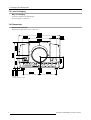


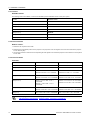


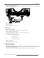
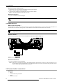
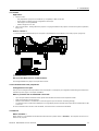
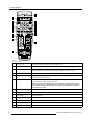

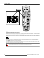
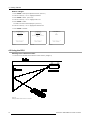
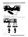

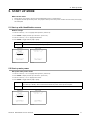


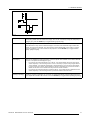
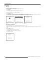
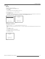
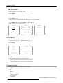

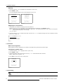
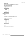

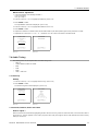
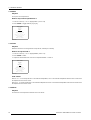

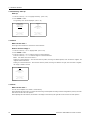
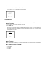
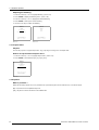


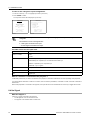
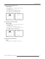
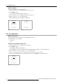
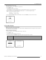
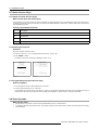
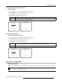
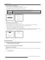
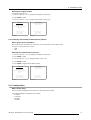


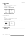


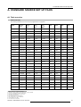
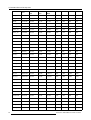
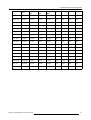

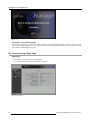
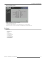
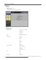
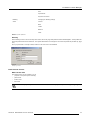
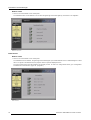
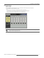


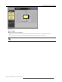
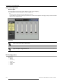
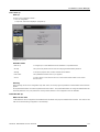
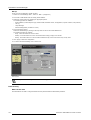
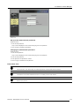
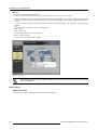
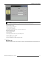
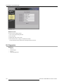
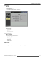
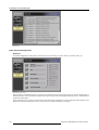
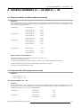
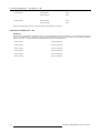
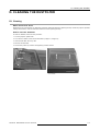


![SLM R12+ Performer [v05]](http://vs1.manualzilla.com/store/data/006296879_1-50504fc86d9979ae79ec928acfe3e08c-150x150.png)