1
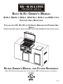
PR EM IU M GR ILL S
Built-In Kit Owner’s Manual
BHA-1, BHAX-1, BBA-1, DPA152-1, BDA-1 and BRB-1 Kits
Outdoor Grill Mountings
For use with P3, R3, H3 or T3 Series Broilmaster Premium Gas
Grills
INSTRUCTIONS MUST BE LEFT WITH THE OWNER FOR FUTURE REFERENCE AFTER INSTALLATION.
Retain Owner’s Manual for Future Reference.
Note: UL Certification extends only to the product, NOT the installation of the product.
GAS-FIRED
Page 1
THIS GAS APPLIANCE IS DESIGNED FOR OUTDOOR USE ONLY.
IMPORTANT
We
advise you to carefully read and follow the instructions in this
Owner’s Manual
before
installing or using your new Broilmaster Built-In Kit. When installed and used as recommended,
your built-in kit will offer years of cooking satisfaction.
this manual.
Please retain it for future reference.
The installer should present you with
WARNING
Reference
this manual for proper installation and maintenance instructions.
Improper
installation, adjustment, alteration, service or maintenance can cause personal injury or
property damage. For assistance or additional information consult a qualified installer, service
agency or the gas supplier.
FOR YOUR SAFETY
IF YOU SMELL GAS:
1.Shut off gas to the appliance.
2.Extinguish any open flame.
3.
Open the grill lid.
4.If odor continues, immediately call your gas supplier or fire department.
5.
Do not touch electrical switches.
FOR YOUR SAFETY
1. Do not store or use gasoline or other flammable vapors and liquids in the vicinity of this or
any other appliance.
2.An LP cylinder not connected for use shall not be stored in the vicinity of this or any other
appliance.
FOR YOUR SAFETY
Be careful when handling parts during assembly and use as they may contain sharp edges.
Work gloves are highly recommended to help prevent possible injury.
All repair part orders should be placed through your local Broilmaster dealer. To locate a dealer in your
area, contact Broilmaster Customer Service at 800-851-3153 • WWW.broilmaster.com. To ensure prompt
and accurate service, please provide the following information when placing a repair part order: Model
number of your Single Door, Part Name, Part Number, and Quantity of parts needed.
Page 2
B101944-0-1212
Table of Contents
Congratulations!
You have chosen the finest Built-In Kit for your outdoor cooking pleasure. Please take time to read this
entire manual before assembling your premium Broilmaster Built-In Kit.
Location, Connections, and Safety................................................................................................. 3 - 4
Enclosure Construction Guidelines..................................................................................................... 5
BHA & BHAX Grill Surround......................................................................................................... 6 - 10
BBA Tank Caddy......................................................................................................................... 11 - 14
DPA152 Side Burner Surround................................................................................................... 15 - 17
BDA Single Door........................................................................................................................ 18 - 21
BRB Vent Register Kit................................................................................................................ 22 - 23
Warranty............................................................................................................................................ 24
Your Broilmaster accessory is identified by model number, serial number, and gas type.
This information is provided on a product identification label located on the accessory. The
grill’s model number, serial number, and gas type must also be provided when contacting
your Broilmaster dealer. For your convenience, complete this section for future reference
when contacting your dealer.
Model No.
Dealer
Serial No.
Gas Type: Propane
B101944-0-1212
Natural
Dealer Phone No.
Date of Purchase
Page 3
Location, Connections, and Safety
Built-In Kit Location
Built-In Kits are designed for outdoor use ONLY.
This Built-In Kit is designed for use with all P3 and T3 Model
Broilmaster gas grills and cannot be used with any other
grill or in any other capacity.
Never install or operate your Built-In Kit in any building,
garage, or other enclosed area.
For your safety, the Built-In Kit should not be installed
or operated under any combustible materials, such as
carports, covered porches, awnings, or overhangs.
Never install or use your Built-In Kit in or on any recreational
vehicle or boat.
CAUTION: THE INSTALLATION AND OPERATION OF
THIS BUILT-IN KIT AT CLEARANCES LESS THAN
SPECIFIED BELOW MAY LEAD TO THE POSSIBILITY
OF FIRE, PROPERTY DAMAGE, OR PERSONAL INJURY.
A minimum clearance of twenty-four (24”) inches is required
from all sides of the island to any combustible material.
Examples of combustible materials are patio furniture,
fences, or the outside of your home.
The area surrounding the built-in kit should be clear to
ensure proper ventilation. Do not obstruct the flow of
combustion and ventilation air in any way. The ventilation
openings on the enclosure must also remain free and clear
of debris.
WARNING: DO NOT INSTALL OR OPERATE THIS BUILTIN KIT WHERE GASOLINE OR OTHER FLAMMABLE
MATERIALS ARE USED OR STORED. FAILURE TO
COMPLY WITH THIS WARNING COULD RESULT IN
EXPLOSION OR FIRE CAUSING PROPERTY DAMAGE
OR PERSONAL INJURY.
CAUTION: THE GRILL AND ITS INDIVIDUAL SHUTOFF
VALVE MUST BE DISCONNECTED FROM THE GAS
SUPPLY PIPING SYSTEM DURING ANY SYSTEM
PRESSURE TESTING AT TEST PRESSURES IN EXCESS
OF 1/2 PSIG.
Checking for Gas Leaks
CAUTION: DO NOT USE AN OPEN FLAME TO CHECK
FOR LEAKS. CHECKING FOR LEAKS WITH AN
OPEN FLAME MAY LEAD TO A FIRE OR EXPLOSION,
RESULTING IN PROPERTY DAMAGE OR PERSONAL
INJURY.
Using the following steps, check for gas leaks during initial
use and each time your Broilmaster gas grill or side burner
is connected to gas or is connected to a cylinder that has
not been used recently
1. Using dish washing detergent and water, make a soapy
solution.
2. Turn OFF the knob on both the grill and side burner’s
control panel.
3. Turn ON the gas at the supply. A hissing sound indicates
a leak. Turn OFF the gas and repair all leaks.
4. If no hissing occurs, apply the soapy solution to all gas
connections.
5. Look for bubbles. Bubbles indicate a leak.
6. If there are bubbles, turn OFF the gas and repair all
leaks.
7. Turn the gas ON and repeat the above procedure until
all leaks are repaired.
Connection Requirements
CAUTION: NEVER USE LIQUID PROPANE GAS IN A
GRILL DESIGNED FOR NATURAL GAS, OR NATURAL
GAS IN A GRILL DESIGNED FOR LIQUID PROPANE
GAS. QUESTIONS REGARDING DIFFERENT TYPES OF
GASES SHOULD BE DIRECTED TO YOUR LOCAL GAS
COMPANY.
Installation must conform to local codes or, in the absence
of local codes, with the National Fuel Gas Code, ANSI
Z223.1. In Canada, installation shall be in accordance with
CAN/CGA-B149.2 Propane Installation Code, or CAN/
CGA-B149.1 Natural Gas Installation Code, and local
codes where applicable. Consult your local gas company or
Propane gas dealer for code regulations and recommended
procedures.
Broilmaster gas grills and side burners are NOT equipped
with pressure regulators. Your Nat. gas grill operates at a
manifold pressure of seven (7”) inches water column.
Page 4
B101944-0-1212
Enclosure Construction Guidelines
Enclosure must be construction from non-combustible material.
If tile is used on the top surface of your enclosure, it may be necessary to enlarge openings at the top edges to allow the
frame pieces of the BHA and BHAX to mount flush against the enclosure.
Screws for enclosure mounting have been supplied. Installer must measure for thickness and use appropriate hardware for
installation. If the enclosure is constructed from masonry materials, it may be necessary to substitute appropriate screws
and fasteners.
This diagram is only a basic plan for constructing an enclosure for your built-in kit. All construction and installation should
comply with all local building codes and requirements.
MINIMUM REQUIREMENTS
Key
Dimension in Inches
Key
Dimension in Inches
A
38” (Minimum)
O
14” (Single) - 27 1/2” (Double)
B
16” (Minimum)
P
15 7/8” (Single) - 9 1/8” (Double)
C
28” (Minimum)
Q
13 15/16”
D
26 13/16”
R
5” (Minimum)
E
10 11/32”
S
24 13/16”
F
12 3/4”
T
24 3/4”
G
6” (Minimum)
U
10”
H
15 3/8”
V
2 1/4”
J
14”
W
2 3/4”
K
19 13/16”
X
9”
L
2 1/2”
Y
3/4” MINIMUM
M
1 11/16”
Z
15 1/4”
N
22 3/8” (Single) - 15 5/8” (Double)
B101944-0-1212
Page 5
BHA-1 & BHAX-1 Grill Surround Kits
Installation Instructions
NOTICE: Refer to the Built-In Kit Enclosure Construction Guide on page 5 for proper
dimensions of the opening for the BHA-1 Grill Surround Kit
Page 6
B101944-0-1212
BHA-1 & BHAX-1 Grill Surround Exploded View & Parts List
All repair part orders should be placed through your local Broilmaster dealer. To locate a dealer in your area, contact
Broilmaster Customer Service at 800-851-3153 • www.broilmaster.com. To ensure prompt and accurate service, please
provide the following information when placing a repair part order: Model Number, Part Name, Part Number, and Quantity
of parts needed.
1
2
3
5
8
4
9
6
7
Index No.
Part No.
1
R2737
2
Description
Quantity
10 x 1/2 Phillips Head Screw
1
B101206
Flexline Bracket
1
3
B101205
Flexline
1
4
B101200
BHA Assembly
1
4
B101529
BHAX Assembly
1
5
B101022
8 x 3/4” Hex Head Screw
8
6
B101178
Grease Tray
1
7
B101204
Control Housing Assembly - BHA
1
7
B101530
Control Housing Assembly - BHAX
1
8
B100113
1/4 - 20 x 1 1/4 Screw (use only with T3/P3 Sereis grill heads)
4
9
B060337
Grease Cup
2
Verify that all parts listed on the exploded view of this manual have been included in this
Built-In Kit before beginning installation.
Caution: Use caution when handling parts, as they may contain sharp edges.
Work gloves are recommended to prevent injury.
Tools Required: Phillips Head Screw Driver (An electric screw driver or drill is recommended to ease installation)
B101944-0-1212
Page 7
BHA & BHAX Assembly
Attention: If applicable, remove protective film from parts
before installation.
3. Place the grease tray into BHA surround by sliding it
under the bracket. See Figure 3.
1. Remove the surround from the shipping box and place
the BHA surround into position in the constructed
enclosure. See Figure 1.
BHA ASSEMBLY
GREASE TRAY
Figure 3
4. Place the control housing assembly into BHA surround
and secure it to the BHA surround. See Figure 4.
BHA ASSEMBLY
CONTROL HOUSING
ASSEMBLY
Figure 1
2. Secure the BHA surround to the enclosure using eight
8 x 3/4” Hex Head Screw screws. See Figure 2.
Note: If you have a masonry structure you may need to
substitute for the appropriate masonry fasteners.
Figure 4
5. Attach the flex line to the bottom of the BHA surround
using the flex line bracket and screw. See Figure 5.
Figure 2
Figure 5
Page 8
B101944-0-1212
BHA & BHAX Assembly
6. After insuring that all the contents are removed from the
inside of the grill, install the grill in the BHA surround by
slightly tilting the grill forward and placing it on the top
of the support bracket. See Figure 6.
Figure 6
7. Mount the grill to the BHA surround using four 1/4-20 x
1 1/4” screws. See Figure 7.
8. Check for gas leaks as discussed in the “Checking for
Gas Leaks” Section of this manual on page 4.
9. Open control housing and connect flex line to the main
valve, then close the control housing door. Figure 8.
Figure 8
Refer to your Grill Head Installation Instructions to complete installation of your Broilmaster grill.
Figure 7
B101944-0-1212
Page 9
BHA & BHAX Assembly
10. Install each of the four vent covers (BRB Vent Register
Kit) into the Built-In Kit Enclosure using two #8 x 3/4”
screws. See Figure 9.
Alternate Match Lighting Instructions
1. Turn the burner control knobs clockwise to the OFF
position.
2. Turn ON gas at the source.
3. Open the grill lid.
4. Open the BHA access door. Locate the Ignitor Rod,
which is permanently attached to the inside of the
Bottom Shelf.
5. Insert an unlit match into the coiled end of the ignitor
rod. Light the match.
6. Insert the ignitor rod inside the access door and through
the front left air hole located on the bottom of the grill.
Position the match near the rear left corner of the
burner. See Figure 10.
7. Turn the left burner control knob counterclockwise to
HI.
8. If the burner fails to light after 5 seconds, turn the
burner control knob OFF for five minutes then repeat
the procedure.
9. If the burner continues not to light, turn OFF all gas and
refer to the troubleshooting section of your grill Owner’s
Manual.
Figure 9
Figure 10
Page 10
B101944-0-1212
BBA-1 TANK CADDY
INSTALLATION INSTRUCTIONS
NOTICE: Refer to the Built-In Kit Enclosure Construction Guide for proper dimensions
of the opening for the BBA-1 Tank Caddy.
THE BBA TANK CADDY IS DESIGNED TO BE USED AS EITHER AN ENCLOSURE FOR A PORTABLE
PROPANE TANK OR A GARBAGE RECEPTACLE. PLEASE REFER TO THE APPROPRIATE SECTIONS OF THIS
MANUAL FOR PROPANE TANK REQUIREMENTS, CONNECTIONS, AND SAFETY.
B101944-0-1212
Page 11
BBA Tank Caddy Exploded View and Parts List
All repair part orders should be placed through your local Broilmaster dealer. To locate a dealer in your area, contact
Broilmaster Customer Service at 800-851-3153 • WWW.broilmaster.com. To ensure prompt and accurate service, please
provide the following information when placing a repair part order: Model number of your Single Door, Part Name, Part
Number, and Quantity of parts needed.
1
3
2
PARTS LIST
Index No.
Part No.
Description
1
B101180
BBA Frame Assembly
Quantity
1
2
B101181
BBA Door Assembly
1
3
B101022
8 x 3/4” Hex Head Screw
8
VERIFY THAT ALL PARTS LISTED IN THE EXPLODED VIEW ON THIS PAGE HAVE BEEN INCLUDED IN
THIS BUILT-IN KIT BEFORE BEGINNING THIS INSTALLATION.
CAUTION: USE CAUTION WHEN HANDLING PARTS, AS THEY MAY CONTAIN SHARP EDGES.
WORK GLOVES ARE RECOMMENDED TO PREVENT INJURY.
Page 12
B101944-0-1212
BBA TANK CADDY INSTALLATION
Recommended Tools: Phillips Screwdriver or an electric
screwdriver.
1. Make sure BBA Tank Caddy opening dimensions match
those in Figure 1. Place the BBA Frame Assembly in
the Built-In Enclosure.
3. While positioned on its side, place the BBA Door
Assembly into the BBA Frame opening. See Figure 2.
BBA FRAME ASSEMBLY
2. Secure the BBA Frame to the Enclosure with eight 8 x
3/4” Hex Head screws as shown in Figure 1.
Note: The hinge pins on the BBA Frame will be located
near the bottom of the Built-In Enclosure when properly
installed. Also See the proper dimensions of the opening
in Figure 1.
13 15/16”
BBA DOOR ASSEMBLY
Figure 2
4. Once located inside the BBA Frame, rotate the BBA
Door to the upright position. See Figure 3.
2413/16”
Figure 3
5. Lower the BBA Door Assembly onto the two hinge pins
inside the lower left and right sides of the BBA Frame.
See Figure 4.
Figure 1
HINGE
PIN
Figure 4
B101944-0-1212
Page 13
BBA TANK CADDY INSTALLATION
ENCLOSURE REQUIREMENTS
The enclosure design must be constructed to allow only
storage of the LP cylinder in use thus preventing storage of
a second cylinder. Tank caddy must be provided for use in
the enclosure when employing the propane self-contained
system so as to prevent the lateral movement of the propane
tank cylinder from its enclosure.
An enclosure for a LP gas cylinder shall be ventilated by
openings at the level of the cylinder valve and at floor level.
The effectiveness of openings(s) for purposes of ventilation
shall be determined with the LP gas supply cylinder in place.
This shall be accompanied by one of the following: enclosure
with one side completely open; or enclosure having four
sides, a top and a bottom. Refer to the Built-In Kit enclosure
construction guide for proper dimensions of the opening for the
BBA-1 Tank Caddy.
1. At least two ventilation openings at cylinder valve level
shall be provided in the side wall, equally sized, spaced
at 180 degrees (3.14 rad), and unobstructed. Each
opening shall have a total free area of not less than
1/2 square inch per pound (7.1 cm2/kg) of stored fuel
capacity and not less than a total free area of 10 square
inches (64.5 cm2).
2. Ventilation opening(s) shall be provided at floor level and
shall have a total free area of not less than 1/2 square
inch per pound (7.1 cm2/kg) of stored fuel capacity and
not less than a total free area of 10 square inches (64.5
cm2). If ventilation openings at floor level are in a side
wall, there shall be at least two openings. The bottom of
the openings shall be at floor level and the upper edge
no more than 5 inches (127 mm) above the floor. The
openings shall be equally sized, spaced at 180 degrees
(3.14 rad) and unobstructed.
3. Every opening shall have minimum dimensions so as
to permit the entrance of an 1/8 inch (3.2 mm) diameter
rod.
The cylinder valve shall be readily accessible for hand
operation. A door on the enclosure to gain access to the
cylinder valves is acceptable, provided it is non-locking and
can be opened without the use of tools.
The enclosure for the LP gas cylinder shall isolate the
cylinder from the burner compartment to provide shielding
from radiant heat, a flame barrier, and protection from
foreign material, such as hot drippings.
There shall be a minimum clearance of 2 inches (50.8 mm)
between the floor of the LP gas cylinder enclosure and the
ground.
The design of the outdoor cooking gas appliance shall
be such that the LP gas cylinder can be connected,
disconnected and the connections inspected and tested
outside the cylinder enclosure; and those connections
which could be disturbed when installing the cylinder in the
enclosure can be leak tested inside the enclosure.
Page 14
B101944-0-1212
DPA152-1 SIDE BURNER SURROUND KIT
INSTALLATION INSTRUCTIONS
NOTICE: Refer to the Built-In Kit Surround Construction Guide for proper dimensions
of the opening for the DPA152-1 Side Burner Surround
THE DPA152 SIDE BURNER SURROUND IS DESIGNED TO BE USED WITH THE DPA150 or DPA151
NATURAL and PROPANE GAS SIDE BURNER ONLY. DO NOT USE ANY OTHER SIDE BURNER WITH THE
DPA152 SIDE BURNER SURROUND.
B101944-0-1212
Page 15
DPA152 Side Burner Surround Exploded View and Parts List
All repair part orders should be placed through your local Broilmaster dealer. To locate a dealer in your area, contact
Broilmaster Customer Service at 800-851-3153 • www.broilmaster.com. To ensure prompt and accurate service, please
provide the following information when placing a repair part order: Model number of your Side Burner, Part Name, Part
Number, and Quantity of parts needed.
1
2
5
3
4
PARTS LIST
Index No.
Part No.
Description
Quantity
1
B101946
LID
1
2
B101945
BASE
1
3
B073963
PIN
4
4
B073967
10-24 KEPS NUT
4
5
B101902
1/4-20 X 1/2 SCREW
4
VERIFY THAT ALL PARTS LISTED IN THE EXPLODED VIEW ON THIS PAGE HAVE BEEN INCLUDED IN
THIS BUILT-IN KIT BEFORE BEGINNING THIS INSTALLATION.
CAUTION: USE CAUTION WHEN HANDLING PARTS, AS THEY MAY CONTAIN SHARP EDGES.
WORK GLOVES ARE RECOMMENDED TO PREVENT INJURY.
Page 16
B101944-0-1212
DPA152 Installation
Recommended Tools: Phillips Screw Driver or an electric
screw driver. A #3 bit is recommended for the 1/4 - 20 x 1/2
screws.
3. Remove lid and place the DPA152 surround into the
enclosure and check for proper hole alignment. Secure
the DPA 152 surround the the enclosure with four
#8x3/4” screws (not supplied). See Figure 3.
1. Make sure the DPA152 surround opening dimensions
match those in Figure 1.
15-1/4”
12-3/4”
Figure 3
Figure 1
2. Before installing built-in surround, peel protective film
from all parts, remove the lid, and unfold mounting
flanges on base. See Figure 2.
4. Attach the gas line to the side burner before installing
into the DPA152 surround. See side burner instructions.
5. Place the side burner into the DPA152 surround. See
Figure 4.
UNFOLDED
MOUNTING FLANGE
Figure 4
Figure 2
6. Align the four holes on the side burner flange with the
four holes on the DPA152 surround and attach ewith
four 1/4-20 x 1/2 screws. See Figure 4.
7. Finish gas line connection and assembly of the side
burner as per the side burner installation instructions.
8. Reinstall lid.
B101944-0-1212
Page 17
BDA-1 SINGLE/DOUBLE DOOR KIT
INSTALLATION INSTRUCTIONS
NOTICE: Refer to the Built-In Surround Construction Guide for proper dimensions of
the opening for the BDA-1 Single/Double Door Kit
THE BDA SINGLE DOOR KIT IS DESIGNED TO BE USED IN AN ISLAND OR OTHER APPLICATION.
Page 18
B101944-0-1212
BDA Single Door Exploded View and Parts List
All repair part orders should be placed through your local Broilmaster dealer. To locate a dealer in your area, contact
Broilmaster Customer Service at 800-851-3153 • www.broilmaster.com. To ensure prompt and accurate service, please
provide the following information when placing a repair part order: Model number of your Single Door, Part Name, Part
Number, and Quantity of parts needed.
1
2
3
4
PARTS LIST
Index No.
Part No.
Description
Quantity
1
B101191
BDA Door Frame
1
2
B101022
8 x 3/4” Hex Head Screw
8
3
B101192
BDA Door
1
4
B101153
BDA Door Bracket (used on double door installation only)
1
VERIFY THAT ALL PARTS LISTED IN THE EXPLODED VIEW ON THIS PAGE HAVE BEEN INCLUDED IN
THIS BUILT-IN KIT BEFORE BEGINNING THIS INSTALLATION.
CAUTION: USE CAUTION WHEN HANDLING PARTS, AS THEY MAY CONTAIN SHARP EDGES.
WORK GLOVES ARE RECOMMENDED TO PREVENT INJURY.
B101944-0-1212
Page 19
BDA Single Door Installation
Attention: If Applicable, remove protective film from
parts before installation.
Recommended Tools: Phillips Screw Driver or an electric
screw driver.
3. Place the Frame into the opening and check for proper
hole alignment. Secure the Frame to the grill enclosure
with eight 8 x 3/4” Hex Head Screw screws. See Figure
3.
1. The BDA Single Door will be fully assembled when it is
shipped out. Remove door from frame by depressing
one of the spring loaded pins and set aside. See Figure
1.
SCREW (8)
Figure 1
Figure 3
2. Make sure BDA Single Door opening dimensions match
those in Figure 2.
4. Secure the BDA Door to the door frame by inserting the
spring loaded pin in the bottom frame hole. Locate the
upper hole in the frame then push on the spring loaded
pin on the door and insert the door in the frame. Figure
4.
14”
Make sure the Door is Aligned and Secured properly by
opening and closing door.
19 13/16”
Figure 2
Figure 4
Page 20
B101944-0-1212
BDA DOUBLE DOOR INSTALLATION
NOTE: You will need two BDA door kits for this installation.
1. Remove doors from frames by depressing one of the
spring loaded pins on each door and set them aside.
Disassemble frame by removing the two screws and
door pin from both door frames as shown in Figure 5.
3. Make sure BDA Double Door opening dimensions
match those in Figure 7. Place the Frame into the opening and check for proper hole alignment. Secure the
Frame to the enclosure with 2 screws. See Figure 7.
4. Secure the Doors to the door frame by inserting the
spring loaded pins in the bottom frame holes. Locate
the upper hole in the BDA frame and push on the spring
loaded pin on the door and insert it into the frame. See
Page 20, Figure 4.
27 ½”
19 13/16”
Figure 5
2. Use the door brackets included in the hardware packages to combine the frames. Use the screws from the
single door to attach the bracket, and place the door pin
in position. See Figure 6
Figure 7
Make sure the Door is Aligned and Secured properly by
opening and closing door.
Figure 6
B101944-0-1212
Page 21
BRB-1 VENT REGISTER KIT
INSTALLATION INSTRUCTIONS
NOTICE: Refer to the Built-In Kit Enclosure Construction Guide for proper dimensions
of the opening for the BRB-1 Vent Register Kit
The BRB Vent Register Kit is designed to be used with any enclosure that has an
LP tank.
Page 22
B101944-0-1212
BRB Vent Register Cover Kit Exploded View and Parts List
All repair part orders should be placed through your local Broilmaster dealer. To locate a dealer in your area,
contact Broilmaster Customer Service at 800-851-3153 • www.broilmaster.com. To ensure prompt and accurate
service, please provide the following information when placing a repair part order: Model number of your Side
Burner, Part Name, Part Number, and Quantity of parts needed.
1
2
PARTS LIST
Index
No.
Part No.
Description
Quantity
1
B071712
Vent Register
2
2
B101022
8 x 3/4” Hex Head Screw
4
Two BRB Vent Register kits are needed for proper installation.
Install two vent registers into each side of the Built-In Kit Enclosure using two screws per vent register.
B101944-0-1212
Page 23
LIMITED WARRANTY
Manufactured in U.S.A. by Broilmaster, a Division of Empire Comfort Systems, Inc.,
P.O. Box 529, Belleville, Illinois 62222.
WHAT IS COVERED AND FOR HOW LONG
From the date these kits are purchased for use, Broilmaster will make available, at our
factory, a free replacement for any defective part covered by this warranty on the following basis:
LIMITED LIFETIME WARRANTY
Stainless Components for Built-In Series (BHA, BBA, DPA152, BDA, & BRB)
PR EM IU M GR ILL S
THE MOST DURABLE GRILL
KNOWN TO MAN
BROILMASTER
A Division of Empire Comfort Systems, Inc.
918 Freeburg Ave.
Belleville, Illinois 62220
Phone: 1-800-851-3153
FAX: 1-800-443-8648
VISIT OUR WEB SITE AT WWW.broilmaster.com
Page 24
B101944-0-1212