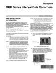
1
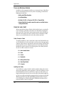
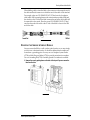
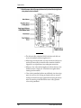
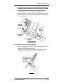
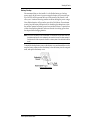
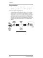
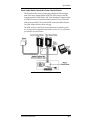
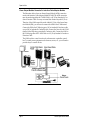
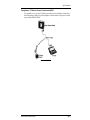
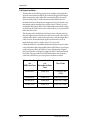
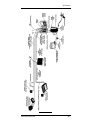
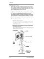
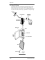
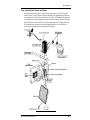
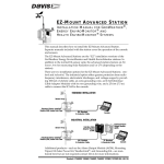
SYSTEM INSTALLATION
FOR INDUSTRIAL GROWEATHER™
AND ENVIROMONITOR™ SYSTEMS
I NTRODUCTION
This manual covers basic industrial GroWeather/EnviroMonitor installation,
including how to connect your sensors to the sensor interface module (SIM)
and how to power your unit. Instructions on installing/mounting sensors and
other system components (such as the Alarm Output Module) are contained in
the manuals for those products. This manual does include several installation
drawings which depict typical GroWeather/EnviroMonitor installations and
should help you connect all of your components correctly.
S YSTEM C OMPONENTS
The system includes the following components. Please make sure you have all
listed components before continuing.
✦ Console with Mounting Base
attached
✦ Sensor Interface Module
✦ 8-foot (2.4-m) 8-Conductor
Cable
✦ Two 16.5-foot (5 m) Ground Wires
(12 AWG)
✦ Three #6 x 1” (25 mm long) Self-Thread-
ing Screws
✦ Two Cable Ties
✦ AC-Power Adapter
✦ Four Adhesive Pads
✦ Two #8 X 3/4” Pan Head Self-
✦ Two Cable Label Sheets
Threading Screws
For 7455 (GroWeather), 7465 (Energy EM), and 7475 (Health EM)
System Installation
T OOLS
AND
M ATERIALS N EEDED
In addition to the components listed above, you may need some of the following tools and materials. Please be sure you have everything you need before
beginning the installation.
✦ Medium-sized Phillips Screwdriver
✦ 9-volt Alkaline Battery
✦ Drill with #36 (.106” or 2.5 mm) and #29 (.136” or 3.5 mm) drill bits
✦ Standard Switch Box (if you wish to mount the console on a wall with the wires
running inside the wall)
U SING
THE
L ABEL S HEET
We have provided two sheets of labels which should aid you in your installation. The majority of the labels on the sheets are cable labels for marking the
ends of each cable. These labels contain connector codes which will help you
attach the correct cable to the correct connector. We have included two label
sheets so you can label both ends of each cable with the same label.
Cable Connector Codes
To simplify installation, we have coded each connector and included the code
on the cable label and on the circuit board or enclosure next to the appropriate
connector. Most connector codes include a letter and a number. The letter identifies the module or unit on which the connector is located while the number
identifies the specific connector. The following letter codes identify the module/unit on which a connector is located.
✦ S = Sensor Interface Module
✦ P = Power
✦ C = Console
✦ L = WeatherLink
✦ B = Battery and Solar Power
✦ A = Alarm Output Module
✦ PC = Computer
Labelling the Cables
Any installation is going to include a number of cables running from various
sensors and components to other components. To alleviate confusion, we have
included label sheets which you should use to mark your cables. Before you
begin installation (but after you have cut each cable to the desired length), lay
out all of your cables and attach the appropriate label to each end of each cable.
Make sure you label every cable end, including extension cables. Doing this
now will help prevent confusion during the installation and whenever you
need to disconnect a sensor/component.
Page 2
Industrial System Installation Manual
Mounting the Sensor Interface Module
When labeling cables, orient the label so the connector code nearest the end of
the cable matches the connector to which that end of the cable will be attached.
For example, place one C2/SENSOR I’FACE/S7 label onto the 8-conductor
cable (which will be running between the sensor interface module (SIM) and
the console) so the C2 side of the label is nearest the end of the cable which will
be connected to the console. Place the second C2/SENSOR I’FACE/S7 label
onto the other end of the cable so the S7 side of the label is closest to the SIM
end of the cable.
LABELING YOUR CABLES
M OUNTING
THE
S ENSOR I NTERFACE M ODULE
You may mount the SIM on a wall or other vertical surface or you may simply
set it down on a horizontal surface. It should be sheltered from weather and
located near a grounding point. You may use our Complete System Shelter
(#7724) or Multi-Purpose Shelter (#7728) to provide protection from weather.
Use our Grounding Kit (#7780) if suitable ground is not otherwise available.
1. Remove the cover by pushing down on the tabs at the top until you can remove the
tabs from the slots.
REMOVE COVER
Industrial System Installation Manual
Page 3
System Installation
2. If you plan to mount the SIM against a wall or other vertical surface, attach the base
to the mounting surface using the #6 x 1” screws. Otherwise skip this step.
Use two screws (as shown below) when attaching to a stud. Use three
screws (as shown below) in any other case. Drill pilot holes using a #36
(.106” or 2.5 mm) drill bit.
ATTACHING TO A WALL OR VERTICAL SURFACE
3. If you plan to place the SIM on a horizontal surface, attach one of the adhesive pads to
each of the four raised circles on the underside of the base as shown below.
ATTACHING ADHESIVE PADS
Page 4
Industrial System Installation Manual
Connecting to the Sensor Interface Module
C ONNECTING
TO THE
S ENSOR I NTERFACE M ODULE
Make sure that you install your sensors and run all necessary cables to the SIM
location before connecting cables to the SIM.
Connecting to the Terminal Blocks
The industrial GroWeather/EnviroMonitor uses terminal blocks containing
high-reliability stainless steel spring-loaded cage clamps. You will be placing
one or two wires into each terminal in order to make the connection. First strip
about 1” (2.5 cm) of the jacket (the grey outer covering) and shield (the foil-like
inner covering) off the cable. Then strip about 5/16” (8 mm) of the insulation
(the colored outer covering) off each wire in the cable. Finally, use a small
screwdriver to push down on the lever next to the terminal, insert the exposed
wire into the opening created, and release the lever. If inserting two wires into
a single terminal, twist the two wires together before inserting. When you
release the lever, the wire(s) will be held in place by the cage clamp.
INSERTING WIRE INTO TERMINAL BLOCK
Connecting to the Sensor Interface Module
1. Attach one end of the 8-conductor cable (which runs from the SIM to the console) to
connector S7.
If using the provided 8-conductor cable to connect the SIM with the console
or the Interface Cable Adapter Module (ICAM), use the modular
connector S7. If using shielded 8-conductor cable to connect the SIM with
the ICAM (you cannot connect shielded cable to the console), connect each
of the wires in your shielded 8-conductor cable to the appropriate terminal
at the terminal block connector S7. Connect the drain wire to the terminal
with the triangle next to it.
Industrial System Installation Manual
Page 5
System Installation
2. Attach the sensor cables to the appropriate terminals (as shown below) using the wire
colors printed on the circuit board.
ATTACHING CABLES
✦ The drain wire (the uninsulated shield wire) from each cable con-
nects to the terminal with the triangle next to it.
✦ When using an extension cable, any extra conductors which are not
used at the sensor cable-to-extension cable connection should be
clipped off to avoid problems at any subsequent connections.
✦ When two color codes are listed together, it indicates that two wires
should be used as a single wire. Twist both wires together before
inserting into the terminal.
✦ Color codes in parenthesis indicate any additional wire color assign-
ments for extension cables. If using an extension cable to connect to
the SIM, twist both listed wires together before inserting into the terminal. If connecting to the SIM with the sensor cable, ignore the
color code in parenthesis.
Page 6
Industrial System Installation Manual
Connecting to the Sensor Interface Module
3. Connect the spade lug on one of the ground wires to the Shield Ground terminal and
the spade lug on the other ground wire to the Circuit Ground terminal. You will need
to connect the ground wires to a suitable ground after you finish installation.
Attaching the ground wire to the Shield Ground terminal is optional,
though it does allow you to take advantage of the SIM’s RFI and surge suppression capabilities. However, you must attach the ground wire to the Circuit Ground terminal.
ATTACHING GROUND WIRES
Routing Cables out of Sensor Interface Module
1. Gather the cables connected on the left of the SIM (including the ground wire) and
secure them to the cable tie lug using a cable tie.
Even if you have only one cable, secure it to provide strain relief. When
tightening the cable tie, make sure the cables are on top of the lug.
SECURE CABLES
Industrial System Installation Manual
Page 7
System Installation
2. Gather the cables connected on the right of the SIM (including the ground wire) and
secure them to the cable tie lug using a cable tie.
Even if you have only one cable, secure it to provide strain relief. When
tightening the cable tie, make sure the cables are on top of the lug.
3. Finally, reattach the cover by putting the cover into place (as shown below) and pushing it onto the base until the tabs on top of the cover snap back into their slots.
Make sure the cables run out the bottom of the SIM as shown below.
REPLACE COVER
C ONNECTING
THE
C ONSOLE
In order to connect the cables to the console, you must remove the mounting
base which comes attached to the console. To remove the mounting base, press
down on the large tab until it is free from its slot and pull the base away from
the console. To connect the console to the SIM (or the ICAM), run the 8-conductor cable to the console and plug it into the jack marked C2 (To Sensor I’face) on
the underside of the console.
Primary Power
The console is powered by 9- to 12-volt DC (direct current). In North America,
the power adapter included with your unit converts 120-volt, 60-Hz AC (alternating current) to 9–volt DC, allowing you to run the unit on ordinary household current. If you are outside North America, in a location where the line
voltage is not 120–volt, 60–Hz, check to see if your local dealer has supplied a
power adapter that is appropriate for your electrical power before you connect
the power adapter to the console. If not, you must use a power converter/
transformer or the appropriate power adapter (9-12-volt, 2.5-mm female plug).
To power the console, simply connect the power adapter to the jack marked
C1 (Power) on the underside of the console. Plug the other end of the power
adapter into an appropriate power outlet. Once connected, the console should
run through a brief self-test procedure. All of the display segments appear, and
the console beeps twice (three times if you have the WeatherLink hardware
module attached). When the self-test finishes, the time (reading 12:00 a.m.)
appears on the display.
Page 8
Industrial System Installation Manual
Connecting the Console
Battery Backup
We recommend that you also install a 9–volt alkaline battery as a backup
power supply. In the event of a power outage, the battery will power the console. Not only will this prevent the loss of data stored by the console, it will
allow you to continue observing weather conditions during the power outage.
New alkaline batteries will power the console for 24–48 hours. For maximum
security, keep the battery backup fresh. You should replace batteries any time
the unit has operated on battery power for more than 18 hours. To prevent loss
of data when replacing batteries, make sure the unit is receiving power from
the adapter before changing batteries.
Note: The use of Ni-Cad batteries is not recommended. Ni-Cad batteries carry less power than alkaline batteries and they will not be recharged by the console. In the event of a power outage, NiCad batteries will be able to power the console for a shorter period of time than alkaline batteries will.
To install the backup battery, remove the battery cover underneath the console,
snap the battery connector onto the battery, lower the battery into the compartment, and replace the battery cover.
INSTALLING BACKUP BATTERY
Industrial System Installation Manual
Page 9
System Installation
D ISPLAYING
THE
C ONSOLE
By changing the orientation of the mounting base, you may display the console
on a tabletop, set it on a shelf, or mount it on a wall.
Selecting a Site for the Console
Unless you use Davis’ Complete System Shelter or a similar weather-proof
shelter, you should locate the console indoors. For more accurate readings, follow these suggestions.
✦ Avoid placing the console in direct sunlight.
The black casing heats up in direct sunlight. This may cause erroneous
readings and/or damage to the unit.
✦ Avoid placing the console near radiant heaters or heating/air conditioning ducts.
✦ If you are mounting the console on a wall, choose an inner or interior wall.
Avoid walls which heat up or cool down depending on the weather.
✦ To connect the console to an 8-conductor cable running inside the wall, attach the
mounting base to an empty switch box, using the two screw holes on the mounting base.
“Horizontal” Orientation
Use this mounting base orientation if the console’s LCD will be below eye level
once the console is positioned. Attach the mounting base as shown below and
then place the console onto any flat surface.
HORIZONTAL ORIENTATION
Page 10
Industrial System Installation Manual
Displaying the Console
“ Vertical” Orientation
Use this mounting base orientation if the console’s LCD will be at or above eye
level once the console is positioned. Attach the mounting base as shown below
and then place the console onto any flat surface.
VERTICAL ORIENTATION
To Display the Console on a Wall
If you want to attach the console to a wall, follow the instructions below.
1. Mark the location of the two keyholes on the back of the mounting base.
2. Use a drill with a #29 (.136” or 3.5-mm) drill bit to make pilot holes in these locations.
3. Drive the two #8 x 3/4” pan head screws into the wall.
Leave at least 1/8” (3 mm) between the wall and the heads of the screw.
4. Attach the mounting base to the console in the vertical orientation position.
5. Slide the keyholes on the back of the mounting base over the two screw heads. Lock
the console into place by gently sliding it downward until it no longer moves.
ATTACHING CONSOLE TO A WALL
Industrial System Installation Manual
Page 11
System Installation
T YPICAL I NSTALLATIONS
The sections that follow show some typical installations to aid you in connecting your system. Specific instructions for mounting and connecting various
sensors and components are contained in the manuals for those components.
WeatherLink with Short-Range Modem Pair
The illustration below shows a WeatherLink connection via our Short-Range
Modem Pair (SRM Pair). The WeatherLink cable plugs into the Short-Range
Modem Adapter in order to connect to one half of the SRM Pair. The other half
of the SRM Pair is connected to a free serial port on your computer. The SRM
Pair is connected using a 2-twisted pair cable (Davis Product #7884) which is
not included. Using 22 AWG cable, you may run up to 4 miles of cable between
the SRM Pair. Using 18 AWG cable, you may run up to 8 miles between the
SRM Pair.
WEATHERLINK WITH SHORT-RANGE MODEM PAIR
Page 12
Industrial System Installation Manual
Typical Installations
Alarm Output Module Connected to Sensor Interface Module
The illustration below shows an Alarm Output Module (AOM) connection
made at the Sensor Interface Module (SIM). The AOM connects to the SIM
using the provided 2’ AOM Cable or a 40’ (12 m) Standard 6-Conductor Extension Cable. You may not extend this distance beyond 40’ (12 m). If the AOM
needs to be more than 40’ (12 m) from the SIM, connect the AOM to the Interface Cable Adapter as shown on the next page.
The AOM can drive control circuits such as thermostats or sprinkler controllers. To control power equipment such as heaters, motors, etc., you will need to
provide relays or control circuits.
ALARM OUTPUT MODULE CONNECTED TO SENSOR INTERFACE MODULE
Industrial System Installation Manual
Page 13
System Installation
Alarm Output Module Connected to Interface Cable Adapter Module
The illustration below shows an Alarm Output Module (AOM) connection
made at the Interface Cable Adapter Module (ICAM). The AOM connection
must be made using either the 2’ AOM Cable or a 40’ (12 m) Standard 6-Conductor Extension Cable. You may not extend this distance beyond 40’ (12 m).
Therefore, if the AOM cannot be located within 40’ (12 m) of the Sensor Interface Module (SIM), you will need to connect the AOM to the ICAM instead.
Connect the SIM to the ICAM using up to 100’ of standard 8-Conductor cable
or up to 200’ of industrial 8-Conductor cable. Connect the Console to the ICAM
(instead of the SIM) using a standard 8-Conductor cable. Connect the AOM to
the ICAM using either the 2’ AOM Cable or a 40’ (12 m) Standard 6-Conductor
Extension Cable.
The AOM can drive control circuits such as thermostats or sprinkler controllers. To control power equipment such as heaters, motors, etc., you will need to
provide relays or control circuits.
ALARM OUTPUT MODULE CONNECTED TO INTERFACE CABLE ADAPTER MODULE
Page 14
Industrial System Installation Manual
Typical Installations
Using Power Y-Cable to Power Console and AOM
It is possible to use a power Y-cable to provide power to both the console and
the AOM using a single AC-power adapter, as shown below. The power Y-cable
is provided with the AOM.
USING POWER Y-CABLE
Industrial System Installation Manual
Page 15
System Installation
Field System Installation
The illustration on the following page shows an example of an installation in
which the sensor interface module is placed outside (using the Multi-Purpose
Shelter for protection) and a single cable is run from the SIM to the console,
which is located indoors. The sensor interface module (SIM) need not be
mounted on the Sensor Mounting Arm support mast; it may be located at any
intermediate point between the sensors and the console. If desired, you may
run shielded cable from the SIM to the ICAM and then run standard 8-Conductor Cable from the ICAM to the console, which will allow you to place the SIM
farther from the console.
This advantage of this installation is that it keeps sensor cable runs relatively
short; the longer portion of the cable run to the console is made with a single 8conductor cable, which is easier to route and lower in cost than multiple sensor
cables. However, the standard cables supplied with the sensors are 40’ in
length which may result in a surplus of up to 30’ (9 m) of cable.
Consult the table below to determine the maximum cable run for power cables
to the AOM and the Multi-Purpose-Shelter Heater (MPS Heater). You will need
to splice the power cable to the AOM’s AC power adapter using a Terminal
Box, Surge Protectors, or Waterproof Crimp-Type Splice Connectors (Terminal
Box shown). The power cable for the MPS Heater connects into the heater’s
control unit, which allows you to turn power to the heater on and off.
MAXIMUM CABLE RUN
Page 16
MAXIMUM CABLE RUN
TYPE OF CABLE
FOR
FOR
AOM POWER CABLE
SHELTER HEATER POWER
CABLE
600 feet (180 m)
100 feet (30 m)
2-Twisted Pair Cable
(#7884)
600 feet (180 m)
100 feet (30 m)
20 AWG Pair (0.75 mm2)
800 feet (240 m)
160 feet (48 m)
18 AWG Pair (1.0 mm2)
1200 feet (360 m)
250 feet (75 m)
16 AWG Pair (1.5 mm2)
Industrial System Installation Manual
Typical Installations
FIELD INTERFACE INSTALLATION
Industrial System Installation Manual
Page 17
System Installation
Field System with AC Power
The illustration below shows an installation in which the console is located
with the SIM (and, optionally, the AOM) in the field near the sensors. The console and modules are housed in the Complete System Shelter (CSS). The Complete-System-Shelter Heater might also be included.
AC power is wired, according to code, to an enclosure or shelter containing a
receptacle box and a power adapter. The power adapter cable is routed into the
CSS, where a power Y-cable distributes power to the console and AOM.
The WeatherLink® (optional) is connected via a Short-Range Modem Pair and
two-twisted-pair cable to a computer in the office at a distance of up to 8 miles,
depending on the wire gauge used. If a cable to the computer is not feasible,
data may be uploaded to a laptop or other portable computer at the sensor site.
The advantages of this system:
✦ The Console is located near the sensors.
Data may be viewed at the sensor site. In addition to making weather
data available in the field, this is useful for the alignment, adjustment,
and monitoring of sensors.
✦ The WeatherLink cable to the computer can be very long, and (comprising only
four conductors) it is low in cost.
The Link cable is also relatively immune to noise and voltage surges, and
additional protection is low in cost.
FIELD SYSTEM WITH AC POWER
Page 18
Industrial System Installation Manual
Typical Installations
Field System with Wired DC Power
This system configuration has the same characteristics and advantages as those
of the AC-powered system described in “Field System with AC Power” on
page 18. In this case AC power is not wired to the site. Rather, the power
adapter is plugged into an available circuit in a sheltered location, and the
(nominal) 12-Volt DC output is supplied to the station with a two-wire cable
(twisted-pair is preferred, but not required). The two wire cable is connected to
the power Y-Cable using a single Surge Protector, Terminal Box, or splice connectors. The Surge Protector may be housed in a Small Surge Protector Shelter
as shown below, or it may be attached to the back panel of the shelter. The table
below lists some recommended maximum distances, which are determined by
the wire gauge used.
MAXIMUM CABLE RUN
TYPE OF CABLE
460 feet (140 m)
24 AWG Pair (.20 mm2)
600 feet (180 m)
22 AWG Pair (.32 mm2)
1000 feet (300 m)
18 AWG Pair (.82 mm2)
FIELD SYSTEM WITH WIRED DC POWER
Industrial System Installation Manual
Page 19
System Installation
Solar-Powered Field System
The illustration below shows an installation in which the Complete System
Shelter (CSS) houses the console, a battery, and the charging regulator. As
shown in “Field System with AC Power” on page 18, data may transmitted via
Link cable, read visually from the display, or uploaded to a computer brought
to the site.
SOLAR POWERED FIELD SYSTEM
Page 20
Industrial System Installation Manual
Typical Installations
Solar-Powered Field System with Radio
The illustration below shows a solar-powered system (see “Solar-Powered
Field System” on page 20) in which the WeatherLink commands and data are
communicated via a user-supplied radio. The 1200- or 2400-baud WeatherLink
is compatible with any transparent communications channel. Because the solar
panel and battery of the Solar Power Kit are not sufficient to supply the radio
for continuous operation, the Alarm Output Module is used to switch on
power to the transmitter for short scheduled periods.
SOLAR-POWERED FIELD SYSTEM WITH RADIO
Industrial System Installation Manual
Page 21
System Installation
“Outbuilding” System Configuration
This variation of the “Field System Installation” (page 16) places the console
and WeatherLink in a barn or other shelter and then uses a Short-Range
Modem Pair (or radio) to communicate with the computer at the “central” site.
The figure below shows the use of Surge Protectors (optional) on the SIM-toconsole and WeatherLink cables.
“OUTBUILDING” SYSTEM CONFIGURATION
Page 22
Industrial System Installation Manual
Typical Installations
“Outbuilding” System Configuration with ICAM and AOM
The figure below shows an “outbuilding” system configuration with the addition of an Interface Cable Adapter Module and Alarm Output Module,
enabling the weather station, the user, or a computer program to provide
inputs to controllers of heaters, fans, motors, or other equipment in the vicinity
of the barn or shelter.
“OUTBUILDING” SYSTEM CONFIGURATION WITH ICAM AND AOM
Industrial System Installation Manual
Page 23
System Installation
For Product Numbers: 7455 (GroWeather), 7465 (Energy EM), and 7475 (Health EM)
Davis Instruments Part Number: 7395-074
Industrial System Installation Manual
Rev. B Manual (7/8/99)
GroWeather and EnviroMonitor are trademarks of Davis Instruments Corp.
WeatherLink is a registered trademark of Davis Instruments Corp.
© Davis Instruments Corp. 1997. All rights reserved.