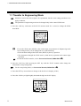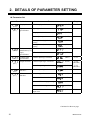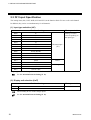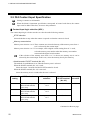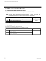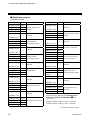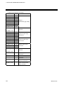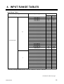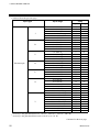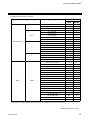
1
Multi-point Digital Controller MA900/MA901 Initial Setting Manual ® RKC INSTRUMENT INC. IMR01H03-E4 !" Modbus is a registered trademark of Schneider Electric. !" Company names and product names used in this manual are the trademarks or registered trademarks of the respective companies. All Rights Reserved, Copyright 2001, RKC INSTRUMENT INC. Thank you for purchasing this RKC instrument. In order to achieve maximum performance and ensure proper operation of your new instrument, carefully read all the instructions in this manual. Please place this manual in a convenient location for easy reference. SYMBOLS WARNING : This mark indicates precautions that must be taken if there is danger of electric shock, fire, etc., which could result in loss of life or injury. CAUTION : This mark indicates that if these precautions and operating procedures are not taken, damage to the instrument may result. ! : This mark indicates that all precautions should be taken for safe usage. : This mark indicates important information on installation, handling and operating procedures. : This mark indicates supplemental information on installation, handling and operating procedures. : This mark indicates where additional information may be located. ! WARNING An external protection device must be installed if failure of this instrument !" could result in damage to the instrument, equipment or injury to personnel. All wiring must be completed before power is turned on to prevent electric !" shock, fire or damage to instrument and equipment. This instrument must be used in accordance with the specifications to prevent !" fire or damage to instrument and equipment. This instrument is not intended for use in locations subject to flammable or !" explosive gases. Do not touch high-voltage connections such as power supply terminals, etc. !" to avoid electric shock. RKC is not responsible if this instrument is repaired, modified or !" disassembled by other than factory-approved personnel. Malfunction can occur and warranty is void under these conditions. IMR01H03-E4 i-1 CAUTION ! This is a Class A instrument. In a domestic environment, this instrument may cause radio interference, in which case the user may be required to take adequate measures. ! This instrument is protected from electric shock by reinforced insulation. Provide reinforced insulation between the wire for the input signal and the wires for instrument power supply, source of power and loads. ! Be sure to provide an appropriate surge control circuit respectively for the following: - If input/output or signal lines within the building are longer than 30 meters. - If input/output or signal lines leave the building, regardless the length. ! This instrument is designed for installation in an enclosed instrumentation panel. All highvoltage connections such as power supply terminals must be enclosed in the instrumentation panel to avoid electric shock by operating personnel. ! All precautions described in this manual should be taken to avoid damage to the instrument or equipment. ! All wiring must be in accordance with local codes and regulations. ! All wiring must be completed before power is turned on to prevent electric shock, instrument failure, or incorrect action. The power must be turned off before repairing work for input break and output failure including replacement of sensor, contactor or SSR, and all wiring must be completed before power is turned on again. ! To prevent instrument damage or failure, protect the power line and the input/output lines from high currents with a protection device such as fuse, circuit breaker, etc. ! Prevent metal fragments or lead wire scraps from falling inside instrument case to avoid electric shock, fire or malfunction. ! Tighten each terminal screw to the specified torque found in the manual to avoid electric shock, fire or malfunction. ! For proper operation of this instrument, provide adequate ventilation for heat dispensation. ! Do not connect wires to unused terminals as this will interfere with proper operation of the instrument. ! Turn off the power supply before cleaning the instrument. ! Do not use a volatile solvent such as paint thinner to clean the instrument. Deformation or discoloration will occur. Use a soft, dry cloth to remove stains from the instrument. ! To avoid damage to instrument display, do not rub with an abrasive material or push front panel with a hard object. ! Do not connect modular connectors to telephone line. NOTICE ! This manual is written for RKC service engineers or qualified technicians. This manual is also prepared especially for readers who already have a fundamental knowledge of electricity, control, computer and communication. ! The figures, diagrams and numeric values used in this manual are only for purpose of illustration. ! RKC is not responsible for any damage or injury that is caused as a result of using this instrument, instrument failure or indirect damage. ! Periodic maintenance is required for safe and proper operation of this instrument. Some components have a limited service life, or characteristics that change over time. ! Every effort has been made to ensure accuracy of all information contained herein. RKC makes no warranty expressed or implied, with respect to the accuracy of the information. The information in this manual is subject to change without prior notice. ! No portion of this document may be reprinted, modified, copied, transmitted, digitized, stored, processed or retrieved through any mechanical, electronic, optical or other means without prior written approval from RKC. i-2 IMR01H03-E4 CONTENTS Page 1. PROCEDURE FOR INITIALIZATION....................................1 1.1 Transfer to Engineering Mode .........................................................................2 1.2 Procedure for Parameter Setting .....................................................................4 1.3 End of Engineering Mode ................................................................................9 2. DETAILS OF PARAMETER SETTING ...............................10 2.1 Attention Items in Setting...............................................................................12 2.2 F10 Display function ......................................................................................17 2.3 F21 Input Specification ..................................................................................18 2.4 F22 Current Transformer (CT) Input Specification ........................................20 2.5 F24 Contact Input Specification.....................................................................22 2.6 F31 Output Function ......................................................................................24 2.7 F32 Alarm Output Function............................................................................26 2.8 F41 Alarm 1 Function/F42 Alarm 2 Function/F43 Alarm 3 Function..............27 2.9 F51 Control Action .........................................................................................29 2.10 F61 Communication Function......................................................................30 2.11 F91 Displayed for Maintenance Information ................................................31 3. INITIALIZE COMMUNICATION DATA................................32 3.1 RKC Communication Protocol .......................................................................32 3.2 Modbus Communication Protocol..................................................................42 3.2.1 Communication data list ...................................................................................42 3.2.2 Data map..........................................................................................................49 4. INPUT RANGE TABLES.....................................................55 IMR01H03-E4 i-3 MEMO i-4 IMR01H03-E4 1. PROCEDURE FOR INITIALIZATION Initialization is to set parameters relating to instrument specifications (input type, input range, alarm type, etc.). Engineering mode that can do this setting. Initialization flowchart !" Power ON Change from RUN to STOP See 1.1 Transfer to Engineering Mode. Unlock the engineering mode See 1.1 Transfer to Engineering Mode. Setting the initial parameter See 1.2 Procedure for Parameter Setting. See 2. DETAILS OF PARAMETER SETTING. Lock the engineering mode See 1.3 End of Engineering Mode. End of initialization IMR01H03-E4 1 1. PROCEDURE FOR INITIALIZATION 1.1 Transfer to Engineering Mode MA900 is used in the below figures for explanation, but the same setting procedures also apply to MA901. The parameter of engineering mode can be changed only in the control STOP state. 1. Press the <R/S key with states of the PV/SV monitor mode for 1 second, to change the STOP from RUN. CH PV AREA SV CH SET R/S MA900 STOP display If set to the STOP state (dSTP) by the contact input, no parameters in Engineering mode can be changed. They can be changed in case of the following. • The instrument changed the STOP state (KSTP) by the key operation. • The instrument changed the STOP state by both the key operation and contact input operation. #) For the RUN/STOP transfer, see the Instruction Manual (IMR01H01-E# 2. Press the <R/S key while pressing the SET key with the PV/SV monitor mode change the instrument to setup setting mode. #). For the setup setting mode, see Instruction Manual (IMR01H01-E# 3. Press the SET key several times to change to the lock level 2 display (LCK2). 4. Press the <R/S key to light brightly the hundreds digit on the SV display. CH PV AREA SV CH SET R/S MA900 Lock level 2 display 2 IMR01H03-E4 1. PROCEDURE FOR INITIALIZATION 5. Press the UP key to change 0 to 1 in the hundreds digit. CH PV AREA SV CH SET Set value 0000: Lock 0100: Unlock R/S MA900 Lock level 2 display 6. Press the SET key to unlock the engineering mode. The display changes to the first parameter in setup setting mode. CH PV CH PV AREA SV AREA SV SET CH R/S MA900 SET CH R/S MA900 Lock level 2 display Autotuning display 7. Press the <R/S key for 2 seconds while pressing the SET key to change the engineering mode. The display changes to the function block F10. CH PV CH PV AREA SV AREA SV SET CH R/S MA900 Autotuning display IMR01H03-E4 CH SET R/S MA900 Function block F10 display Engineering mode 3 1. PROCEDURE FOR INITIALIZATION 1.2 Procedure for Parameter Setting Flowchart of displaying parameter items !" Display flowcharts in engineering mode are shown in the following. [ : Press the SET key : Press the UP or DOWN key] STOP display selection PV Return to the F10 SV (F10.) (SPCH) Input type selection Display unit selection Decimal point position setting Setting limiter (high limit) setting Setting limiter (low limit) setting Return to the F21. (F21.) (InP) (UnIT) CT ratio 1 selection CT ratio 2 selection (PGdP) (SLH) (SLL) Return to the F22. (F22.) (CTr1) (CTr2) Any parameter whose channel number is displayed can be set for each channel. (Check the channel number on the channel display of instrument.) All of the channels can be simultaneously set as the same value. Contact input logic selection Return to the F24. (dlSL) (F24.) Control output logic selection 1 All the setting item is displayed regard less of the contents of the instrument specification. Control output logic selection 2 Return to the F31. (F31.) (LGo1) (LGo2) Alarm output logic selection Return to the F32. (LGA) (F32.) Alarm 1 Alarm type selection Alarm hold action selection Alarm differential gap setting Alarm timer setting Action selection at input error Return to the F41. (AS1) (F41.) A 4 (AHo1) (AH1) (ALT1) (AEo1) B IMR01H03-E4 1. PROCEDURE FOR INITIALIZATION A B Alarm 2 Alarm type selection Alarm hold action selection Alarm differential gap setting Alarm timer setting Action selection at input error Return to the F42. (F42.) (AS2) Alarm 3 Alarm type selection (AHo2) Alarm hold action selection (AH2) (ALT2) (AEo2) Alarm differential gap setting Alarm timer setting Action selection at input error Return to the F43. (F43.) (AS3) (AHo3) (AH3) Control action type selection ON/OFF action differential gap setting (ALT3) (AEo3) Return to the F51. (F51.) (oS) (oH) Communication protocol selection RUN/STOP transfer logic selection Return to the F61. (F61.) (CMPS) (CMLG) ROM version display Integrated operating Integrated operating time display Holding peak ambient time display (Lower 4 digits) temperature display (Upper 3 digits) Return to the F91. (F91.) IMR01H03-E4 (E261) (WTH) (WTL) (TCJ) 5 1. PROCEDURE FOR INITIALIZATION !" Example of changing the setting As setting procedure example, show procedure at setting with each channel (Usual setting) and channel common (Batch setting). MA900 is used in the below figures for explanation, but the same setting procedures also apply to MA901. Example 1: The following procedure is for changing the CH1 input type from “K” to “J.” (Usual setting) 1. Press the UP key to change the display to F21. CH PV AREA SV CH SET R/S MA900 Function block display 2. Press the SET key to change to input type selection (InP). CH PV AREA SV CH SET R/S MA900 Input type selection 3. Press the UP key to enter 1 in the least significant digit of the set value (SV) display. CH PV AREA SV CH SET R/S MA900 Input type selection 6 IMR01H03-E4 1. PROCEDURE FOR INITIALIZATION 4. Press the SET key to register the value thus set. The display changes to the next parameter. CH PV CH PV AREA SV AREA SV CH SET R/S CH MA900 SET R/S MA900 Input type selection Display unit selection Example 2: The following procedure is for changing all channels of the input type from “K” to “J.” (Batch setting) 1. Press the UP key to change the display to F21. CH PV AREA SV CH SET R/S MA900 Function block display 2. Press the SET key to change to input type selection (InP). CH PV AREA SV CH SET R/S MA900 Input type selection IMR01H03-E4 7 1. PROCEDURE FOR INITIALIZATION 3. Press the CH key several times. Display the character A on the CH display and “----” on the SV display. The character A indicates that the batch setting. CH PV AREA SV CH SET R/S MA900 Input type selection Every time the CH key is pressed, the channel number changes as follows. 4. Press the UP key several times to enter 1 in the least significant digit of the set value (SV) display. CH PV AREA SV CH SET R/S MA900 Input type selection 5. Press the SET key to register the value thus set. The display changes to the next parameter. Press the CH key to return to the usual setting from the batch setting. CH PV CH PV CH PV AREA SV AREA SV AREA SV CH SET R/S MA900 CH SET R/S MA900 Input type selection CH SET R/S MA900 Display unit selection Display unit selection (Batch setting) (Usual setting) If the selected parameter corresponds to the setting item in common to all channels, the simultaneous setting state returns to the normal setting state. 8 IMR01H03-E4 1. PROCEDURE FOR INITIALIZATION 1.3 End of Engineering Mode MA900 is used in the above figures for explanation, but the same setting procedures also apply to MA901. 1. Transfer to function block symbol display (F## ) after each parameter is set. 2. Press the <R/S key for 2 seconds while pressing the SET key to change to the PV/SV monitor mode from the engineering mode. 3. Press the <R/S key while pressing the SET key with the PV/SV monitor mode change the instrument to setup setting mode. 4. Press the SET key several times to change to the lock level 2 display (LCK2). 5. Press the <R/S key to light brightly the hundreds digit on the SV display. 6. Press the DOWN key to change 1 to 0 in the hundreds digit. CH PV AREA SV CH SET Set value 0000: Lock 0100: Unlock R/S MA900 Lock level 2 display 7. Press the SET key to lock the engineering mode. The display changes to the first parameter in setup setting mode. CH PV CH PV AREA SV AREA SV CH SET R/S MA900 Lock level 2 display SET CH R/S MA900 Autotuning display 8. Press the <R/S key while pressing the SET key to change to the PV/SV monitor mode from the setup setting mode. Thus, the initialization ends. IMR01H03-E4 9 2. DETAILS OF PARAMETER SETTING !" Parameter list Function block Parameter Page Display function STOP display selection (SPCH) P. 17 Input specification Input type selection (InP) P. 18 Display unit selection (UnIT) Decimal point position selection (PGdP) Setting limiter (high limit) setting Setting limiter (low limit) setting CT ratio 1 selection (SLH) (F10.) (F21.) (F22.) (F24.) (SLL) Current transformer (CT) input CT ratio 2 selection specification Contact input Contact input logic selection specification Output function Control output logic selection 1 (CTr1) (dISL) P. 22 (LGo1) Control output logic selection 2 (LGo2) Alarm output logic selection (LGA) P. 24 (MA900) P. 25 (MA901) P. 26 (F41.) Alarm 1 type selection (AS1) P. 27 Alarm 1 hold action selection (AHo1) Alarm 1 differential gap setting (AH1) Alarm 1 timer setting (ALT1) Alarm 1 action selection at input error (AEo1) Alarm output function Alarm 1 function P. 20 (CTr2) (F31.) (F32.) P. 19 P.28 P. 29 Continued on the next page. 10 IMR01H03-E4 2. DETAILS OF PARAMETER SETTING Continued from the previous page. Function block (F42.) (F43.) Alarm 2 function Alarm 3 function Control action Parameter Page Alarm 2 type selection (AS2) P. 27 Alarm 2 hold action selection (AHo2) Alarm 2 differential gap setting (AH2) Alarm 2 timer setting (ALT2) Alarm 2 action selection at input error Alarm 3 type selection (AEo2) P. 29 (AS3) P. 27 Alarm 3 hold action selection (AHo3) Alarm 3 differential gap setting (AH3) Alarm 3 timer setting (ALT3) Alarm 3 action selection at input error Control action type selection (AEo3) P. 29 (oS1) P. 29 P. 28 P. 28 (F51.) (F61.) (F91.) IMR01H03-E4 Communication function Displayed for maintenance information ON/OFF action differential gap setting Communication protocol selection RUN/STOP transfer logic selection ROM version display Integrated operating time (Upper 3 digits) display Integrated operating time (Lower 4 digits) display Holding peak ambient temperature display (oH) (CMPS) P. 30 (CMLG) (E261) P. 31 (WTH) (WTL) (TCJ) 11 2. DETAILS OF PARAMETER SETTING 2.1 Attention Items in Setting If any of the following parameter is changed, the relevant set value is initialized or is automatically converted. Before changing the set values, always record all of them (SV setting & CT monitor mode, setup setting mode, parameter setting mode and engineering mode). After changing the set values, always check all of them (SV setting & CT monitor mode, setup setting mode, parameter setting mode and engineering mode). When changed parameter of input type selection or engineering unit setting !" When change a input type and unit, all the set value of a list shown below is initialized. Set it in value to use once again. Mode Description Default value TC input Engineering mode Setup setting mode Decimal point position Setting limiter [high limit] Setting limiter [low limit] Alarm 1 hold action Alarm 1 differential gap Alarm 1 action at input error Alarm 2 hold action Alarm 2 differential gap Alarm 2 action at input error Alarm 3 hold action Alarm 3 differential gap Alarm 3 action at input error ON/OFF action differential gap Heater break alarm 1 Heater break alarm 2 3 PV bias Digital filter 1 RTD input 0 Maximum settable value Voltage input 1 2 100.0 % 0.0 % 0 (Without alarm hold action) 2 °C [°F] 2.0 °C [°F] 0.2 % of span 0 (Without action at input error) 0 (Without alarm hold action) 2 °C [°F] 2.0 °C [°F] 0.2 % of span 0 (Without action at input error) 0 (Without alarm hold action) 2 °C [°F] 2.0 °C [°F] 0.2 % of span 0 (Without action at input error) 2 °C [°F] 2.0 °C [°F] 0.2 % of span OFF OFF 0 °C [°F] 0.0 °C [°F] 0.0 % OFF 1 0: No digit below decimal point 1: 1 digit below decimal point 3 In case of MA901, this item is not provided. 2 Continued on the next page. 12 IMR01H03-E4 2. DETAILS OF PARAMETER SETTING Continued from the previous page. Mode Parameter setting mode SV setting & CT monitor mode Description Control loop break alarm Control loop break alarm deadband Alarm 1 Alarm 2 Alarm 3 Heat-side proportional band Integral time Derivative time Anti-reset windup Cool-side proportional band * Overlap/deadband * Setting changing rate limiter Set value (SV) Default value TC input RTD input Voltage input 0 °C [°F] 8.0 minutes 0.0 °C [°F] 0.0 % 50 °C [°F] 50.0 °C [°F] 5.0 % of span 30 °C [°F] 30.0 °C [°F] 3.0 % of span 240 seconds 60 seconds 100 % 100 % of heat-side proportional band 0 °C [°F] 0.0 °C [°F] 0.0 % OFF 0 °C [°F] 0.0 °C [°F] 0.0 % * In case of MA901, these items are not provided. IMR01H03-E4 13 2. DETAILS OF PARAMETER SETTING When changed parameter of decimal point position setting !" When change a decimal point position, it is converted into about set value of a list shown below automatically. However, the set value may change as a result of changing the position of the decimal point. Therefore in that case, re-set it to the value to be used. Mode Description Setting limiter [high limit] Setting limiter [low limit] Alarm 1 differential gap Alarm 2 differential gap Alarm 3 differential gap ON/OFF action differential gap PV bias Control loop break alarm deadband Alarm 1 Alarm 2 Alarm 3 Heat-side proportional band Overlap/deadband * Setting changing rate limiter Set value (SV) Engineering mode Setup setting mode Parameter setting mode SV setting & CT monitor mode * In case of MA901, this item is not provided. Example and caution of automatic conversion • Decimal point location moves in accordance with it when increases decimal point location. Example: When the position of the decimal point changed from 0 to 1 with SLH set to 800 °C. (Changed from 800 to 800.0) (SLH) (SLH) • If the setting range is not between −1999 and +9999 regardless of the position of the decimal point, it is limited by the range from −1999 to +9999. Example: Suppose set SLH is 1372 °C, if change decimal point position from 0 to 1. SLH becomes 999.9 as it exceeds the setting range. (SLH) (SLH) Continued on the next page. 14 IMR01H03-E4 2. DETAILS OF PARAMETER SETTING Continued from the previous page. • If the number of digits below the decimal point is changed in the decreasing direction, the decreased number of digits is omitted. Example: Suppose set SLH is 99.99, if change decimal point position from 0 to 2. The figures below the decimal point are omitted, and as a result SLH becomes 99. (SLH) (SLH) In the above example, it the position of the decimal point is returned to 2 from 0, SLH becomes 99.00. • Set SLL and SLH so that SLL may not be equal to SLH when the position of the decimal point is changed. Otherwise malfunction may result. Example: When the position of the decimal point is changed to 0 at SLL=999.1 and SLH=999.9 (SLL) (SLH) (SLL) (SLH) When changed parameter of setting limiter [high limit/low limit] !" When change setting limiter [high limit/low limit], all the set value of a list shown below is initialized. Set it in value to use once again. However no change is made if the set value is within the range changed. Mode Engineering mode Setup setting mode Parameter setting mode SV setting & CT monitor mode Description Alarm 1 differential gap Alarm 2 differential gap Alarm 3 differential gap ON/OFF action differential gap PV bias Control loop break alarm deadband Alarm 1 Alarm 2 Alarm 3 Heat-side proportional band Overlap/deadband * Setting change rate limiter Set value (SV) * In case of MA901, this item is not provided. Example: For temperature input, voltage/current inputs If the setting is made so that the span becomes narrower, there may be a case where the related set value becomes smaller or 0. IMR01H03-E4 15 2. DETAILS OF PARAMETER SETTING When changed parameter of alarm type selection !" When change alarm 1 type and alarm 2 type, all the set value of a list shown below is initialized. Set it in value to use once again. Mode Description Default value TC input Engineering mode Setup setting mode Parameter setting mode Alarm 1 hold action Alarm 1 differential gap Alarm 1 action at input error Alarm 2 hold action Alarm 2 differential gap Alarm 2 action at input error Alarm 3 hold action Alarm 3 differential gap Alarm 3 action at input error Heater break alarm 1 Heater break alarm 2 * Control loop break alarm Control loop break alarm deadband Alarm 1 Alarm 2 Alarm 3 RTD input Voltage input 0 (Without alarm hold action) 2 °C [°F] 2.0 °C [°F] 0.2 % of span 0 (Without action at input error) 0 (Without alarm hold action) 2 °C [°F] 2.0 °C [°F] 0.2 % of span 0 (Without action at input error) 0 (Without alarm hold action) 2 °C [°F] 2.0 °C [°F] 0.2 % of span 0 (Without action at input error) OFF OFF 8.0 minutes 0 °C [°F] 0.0 °C [°F] 0.0 % 50 °C [°F] 50.0 °C [°F] 5.0 % of span * In case of MA901, this item is not provided. 16 IMR01H03-E4 2. DETAILS OF PARAMETER SETTING 2.2 F10 Display function (1) STOP display selection (SPCH) Details of setting 0000 0001 Factory set value STOP is displayed on the PV display unit. (TYPE 1) STOP is displayed on the SV display unit. (TYPE 2) 0000 Displays in the STOP mode become as follows. (KSTP) TYPE 1 (SPCH=0000) TYPE 2 (SPCH=0001) (SToP) PV PV SV SV SV PV PV PV SV SV SV (KSTP) IMR01H03-E4 (dSTP) PV (dSTP) (SToP) 17 2. DETAILS OF PARAMETER SETTING 2.3 F21 Input Specification The setting items (InP, UnIT, PGdP, SLH and SLL) in the function block F21 are set for each channel. In addition, they can be set simultaneously for all channels. (1) Input type selection (InP) 0000 0001 0002 0003 0004 0005 0006 0007 0008 0009 0010 0011 0012 0013 0014 0015 0016 Details of setting Factory set value K J R S B E N T W5Re/W26Re PL II U L Pt100 JPt100 0 to 5 V DC 1 to 5 V DC 0 to 10 V DC Factory set value varies depending on the input type. Thermocouple * (TC) RTD * Voltage * * Input type cannot be changed because the hardware is different. See 2.1 Attention Items in Setting (P. 12). (2) Display unit selection (UnIT) Details of setting 0000 0001 °C °F Factory set value 0000 The invalidity in case of the voltage inputs. See 2.1 Attention Items in Setting (P. 12). 18 IMR01H03-E4 2. DETAILS OF PARAMETER SETTING (3) Decimal point position setting (PGdP) Details of setting 0000 0001 0002 0003 Factory set value No digit below decimal point (!!!!) 1 digit below decimal point (!!!.!) 2 digits below decimal point (!!.!!) * 3 digits below decimal point (!.!!!) * Note 1 * When input type is thermocouple and RTD, no setting can be changed. Note 1 Factory set value varies depending on the instrument specification. See. 2.1 Attention Items in Setting (P. 12). (4) Setting limiter [high limit] (SLH) Setting limiter [low limit] (SLL) Details of setting K J Thermocouple R S B E N T W5Re/W26Re PL II U RTD Voltage 1 2 2 L Pt100 (JIS/IEC 1) JPt100 (JIS) 0 to 5 V DC 1 to 5 V DC 0 to 10 V DC −199 to +1372 °C (−326 to +2502 °F) −199.9 to +999.9 °C (−199.9 to +999.9 °F) −199 to +1200 °C (−326 to +2192 °F) −199.9 to +999.9 °C (−199.9 to +999.9 °F) 0 to 1769 °C (0 to 3216 °F) 0 to 1769 °C (0 to 3216 °F) 0 to 1820 °C (0 to 3308 °F) 0 to 1000 °C (0 to 1832 °F) 0 to 1300 °C (0 to 2372 °F) 0 to 999.9 °C (0 to 999.9 °F) −199 to +400 °C (−326 to +752 °F) −199.9 to +400.0 °C (−199.9 to +752.0 °F) 0 to 2320 °C (0 to 4208 °F) 0 to 1390 °C (0 to 2534 °F) −199 to +600 °C (−326 to +1112 °F) −199.9 to +600.0 °C (−199.9 to +999.9 °F) 0 to 900 °C (0 to 1652 °F) −199.9 to +649.0 °C (−199.9 to +999.9 °F) −1999 to +9999 (programmable scale) Factory set value Factory set value varies depending on the instrument specification. SLH: 100.0 SLL: 0.0 IEC (International Electrotechnical Commission) is equivalent to JIS, DIN and ANSI. In case of voltage/current inputs, SLH can be set below SLL. Set the setting limiter referring to the 4. INPUT RANGE TABLES (P. 55). See. 2.1 Attention Items in Setting (P. 12). IMR01H03-E4 19 2. DETAILS OF PARAMETER SETTING 2.4 F22 Current Transformer (CT) Input Specification If the heater break alarm is selected as the alarm 2, the number of turns * of the current transformer (CT) used is set for each channel. In addition, it can be set simultaneously for all channels. * The number of turns = CT ratio The heater break alarm for three-phase heater can not be specified with MA901. When the MA901 instrument specification corresponds to contact input or communication function, the heater break alarm can't be added. Therefore, do not use this parameter. CT ratio 1 selection (CTr1) [Heater break alarm for single-phase heater or "# heater break alarm for three-phase heater (Z-168) ] CT ratio 2 selection (CTr2) [Heater break alarm for three-phase heater (Z-168) ] The setting the CT ratio from CT1 to CT4 can be made when the CT ratio 1 (CTr1) of MA900 is selected. The setting the CT ratio from CT1 to CT8 can be made when the CT ratio 1 (CTr1) of MA901 is selected. The setting the CT ratio from CT5 to CT8 can be made when the CT ratio 2 (CTr2) is selected. CH PV CH PV AREA SV AREA SV SET CH R/S Set the CT ratio. MA900 CH SET R/S MA900 CT ratio 1 selection (CTr1) CT ratio 2 selection (CTr2) Setting method When the CTL-6-P-N current transformer is used, set the CT ratio to 800. When the CTL-12-S56-10L-N current transformer is used, set the CT ratio to 1000. Details of setting 0 to 9999 Factory set value CTL-6-P-N: 800 CTL-12-S56-10L-N: 1000 MA900 (Heater break alarm for single-phase heater) CH display PV display 1 CTr1 Details of setting Set the CT ratio of CT1. 2 Set the CT ratio of CT2. 3 Set the CT ratio of CT3. 4 Set the CT ratio of CT4. Continued on the next page. 20 IMR01H03-E4 2. DETAILS OF PARAMETER SETTING Continued from the previous page. MA900 (Heater break alarm for three-phase heater) CH display PV display 1 CTr1 Details of setting Set the CT ratio of CT1. 2 Set the CT ratio of CT2. 3 Set the CT ratio of CT3. 4 Set the CT ratio of CT4. 1 CTr2 Set the CT ratio of CT5. 2 Set the CT ratio of CT6. 3 Set the CT ratio of CT7. 4 Set the CT ratio of CT8. The CT ratio 2 selection (CTr2) is displayed when the instrument specification is three-phase heater. MA901 (Heater break alarm for single-phase heater) CH display PV display 1 CTr1 IMR01H03-E4 Details of setting Set the CT ratio of CT1. 2 Set the CT ratio of CT2. 3 Set the CT ratio of CT3. 4 Set the CT ratio of CT4. 5 Set the CT ratio of CT5. 6 Set the CT ratio of CT6. 7 Set the CT ratio of CT7. 8 Set the CT ratio of CT8. 21 2. DETAILS OF PARAMETER SETTING 2.5 F24 Contact Input Specification Setting is common to all channels. When the MA901 instrument specification corresponds to heater break alarm, the contact input can't be added. Therefore, do not use this parameter. Contact input logic selection (diSL) "# The contact input logic selection sets the set value about the following contents. • STOP selection Selected whether to stop when the contact is opened or when the contact is closed. • Memory area selection Memory area selection 1 to 8: These contents are selected when any of the memory areas from 1 to 8 is selected by the contact input. Memory area selection 1 to 7: For example, when a digital switch starting from “0” is used, select the memory area number when the memory area number must match the digital switch number. If the selection of the memory areas from 1 to 7 is chosen, no memory area 8 can be selected by the contact input. In this case, select the memory area by the front key. • Used/unused of DI SET terminal (No. 43) The method of establishment is set when the memory area is selected. When the DI SET terminal (No. 43) is used: Select the area 0.5 seconds after the DI SET terminal is closed. When the DI SET terminal (No. 43) is not used: Select the memory area 2 seconds after the area is selected. Details of setting 0000 0001 0002 STOP selection When contact input (RUN/STOP transfer) opens, stop. When contact input (RUN/STOP transfer) opens, stop. When contact input (RUN/STOP transfer) opens, stop. Memory area selection Used/unused of DI SET terminal (No. 43) Factory set value Memory area transfer 1 to 8 Used 0000 Memory area transfer 1 to 8 Unused Memory area transfer 1 to 7 Used Continued on the next page. 22 IMR01H03-E4 2. DETAILS OF PARAMETER SETTING Continued from the previous page. Details of setting STOP selection Memory area selection Used/unused of DI SET terminal (No. 43) 0003 When contact input (RUN/STOP transfer) opens, stop. When contact input (RUN/STOP transfer) opens, stop. When contact input (RUN/STOP transfer) is closed, stop. When contact input (RUN/STOP transfer) is closed, stop. When contact input (RUN/STOP transfer) is closed, stop. When contact input (RUN/STOP transfer) is closed, stop. When contact input (RUN/STOP transfer) is closed, stop. Memory area transfer 1 to 7 Unused 0004 0005 0006 0007 0008 0009 IMR01H03-E4 There is no memory area transfer function. Unused Memory area transfer 1 to 8 Used Memory area transfer 1 to 8 Unused Memory area transfer 1 to 7 Used Memory area transfer 1 to 7 Unused There is no memory area transfer function. Factory set value 0000 Unused 23 2. DETAILS OF PARAMETER SETTING 2.6 F31 Output Function "# MA900 (1) Control output logic selection 1 (LGo1) This data is 0000 fixation. This data must not set the set value besides 0000. Channel display Output number 1 2 3 4 OUT1 OUT2 OUT3 OUT4 Details of setting 0000: Heat-side control output of CH1 0000: Heat-side control output of CH2 0000: Heat-side control output of CH3 0000: Heat-side control output of CH4 Factory set value 0000 (2) Control output logic selection 2 (LGo2) Select the output logic of the output 2 (OUT5 to OUT8). The channel number displayed on the CH display unit corresponds to the relevant output number. The setting is made for each channel number. In addition, OUT5 to OUT8 can be simultaneously set. Conduct setting so as to meet the instrument specification. An incorrect setting may cause a malfunction. 1 2 Channel display Output number 1 OUT5 2 OUT6 3 OUT7 Details of setting 0000: No output 0001: Cool-side control output of CH1 1 0002: No output 0003: No output 0004: Alarm 3 of CH1 2 0005: Alarm 3 of CH2 2 0006: Alarm 3 of CH3 2 0007: Alarm 3 of CH4 2 0008 to 0011: No output 0000: No output 0001: Cool-side control output of CH2 1 0002 to 0007: Same as OUT5 0008 to 0011: No output 0000: No output 0001: Cool-side control output of CH3 1 0002 to 0007: Same as OUT5 0008 to 0011: No output Factory set value Factory set value varies depending on the instrument specification. Setting becomes effective at the time of heat/cool control. Not output when alarm 3 corresponds to the FAIL alarm. Continued on the next page. 24 IMR01H03-E4 2. DETAILS OF PARAMETER SETTING Continued from the previous page. MA900 Channel display 4 * Output number OUT8 Details of setting 0000: No output 0001: Cool-side control output of CH4 * 0002 to 0007: Same as OUT5 0008 to 0011: No output Factory set value Factory set value varies depending on the instrument specification. Setting becomes effective at the time of heat/cool control. "# MA901 (1) Control output logic selection 1 (LGo1) This data is 0000 fixation. This data must not set the set value besides 0000. Channel display Output number 1 2 3 4 OUT1 OUT2 OUT3 OUT4 Details of setting 0000: Heat-side control output of CH1 0000: Heat-side control output of CH2 0000: Heat-side control output of CH3 0000: Heat-side control output of CH4 Factory set value 0000 (2) Control output logic selection 2 (LGo2) This data is 0000 fixation. This data must not set the set value besides 0000. Channel display Output number 1 2 3 4 OUT5 OUT6 OUT7 OUT8 IMR01H03-E4 Details of setting 0000: Heat-side control output of CH5 0000: Heat-side control output of CH6 0000: Heat-side control output of CH7 0000: Heat-side control output of CH8 Factory set value 0000 25 2. DETAILS OF PARAMETER SETTING 2.7 F32 Alarm Output Function Alarm output logic selection (LGA) "# Select the alarm output logic of alarm 1 (Normal equipment), alarm 2 (Option) and alarm 3 (Option). The channel number displayed on the CH display unit corresponds to the relevant alarm. The setting is made for each channel number. In addition, output logic of alarm 1 to alarm 3 can be simultaneously set. Conduct setting so as to meet the instrument specification. An incorrect setting may cause a malfunction. Channel display Alarm Details of setting Factory set value 1 ALM1 [Alarm 1] 0001 2 ALM2 [Alarm 2] ALM3 [Alarm 3] 0000: FAIL alarm 0001: Logical OR of alarm 1 in all channels (Energized) 0002: Logical OR of alarm 2 in all channels (Energized) 0003: Logical OR of alarm 3 in all channels (Energized) 0004: Logical OR of alarm 1 and alarm 2 in all channels (Energized) 0005: Logical OR of alarm 1 and alarm 3 in all channels (Energized) 0006: Logical OR of alarm 2 and alarm 3 in all channels (Energized) 0007: Logical OR of alarm 1, alarm 2 and alarm 3 in all channels (Energized) 0008: Logical OR of alarm 1 in all channels (De-energized) 0009: Logical OR of alarm 2 in all channels (De-energized) 0010: Logical OR of alarm 3 in all channels (De-energized) 0011: Logical OR of alarm 1 and alarm 2 in all channels (De-energized) 0012: Logical OR of alarm 1 and alarm 3 in all channels (De-energized) 0013: Logical OR of alarm 2 and alarm 3 in all channels (De-energized) 0014: Logical OR of alarm 1, alarm 2 and alarm 3 in all channels (De-energized) 0000 to 0014: Same as ALM1 0002 0000 to 0014: Same as ALM1 0003 3 Alarm output is only relay contact output. 26 IMR01H03-E4 2. DETAILS OF PARAMETER SETTING 2.8 F41 Alarm 1 Function F42 Alarm 2 Function F43 Alarm 3 Function (1) Alarm type selection (AS1, AS2, AS3) Details of setting 1 0000 0001 0002 0003 0004 0005 0006 0007 0008 0009 0010 Alarm not provided SV high alarm SV low alarm Process high alarm Process low alarm Deviation high alarm Deviation low alarm Deviation high/low alarm Band alarm Control loop break alarm 2 Heater break alarm 3, 4 Factory set value Factory set value varies depending on the instrument specification. 1 When instrument specification is failure alarm, set 0000. When control action type is heat/cool control, do not select. 3 When control output is current output, do not select. 4 When the contact input or the communication function is selected as instrument specifications of MA901, the heater break alarm can’t be added. See 2.1 Attention Items in Setting (P. 12). 2 (2) Alarm hold action selection (AHo1, AHo2, AHo3) Details of setting 0000 0001 Without alarm hold action Effective when the power is turned on, or operation is changed from STOP to RUN. Valid when: • the power is turned on, • operation is changed from STOP to RUN, • the SV is changed, or • the memory area (control area) is changed. 0002 Factory set value Without alarm hold action: 0000 With alarm hold action: 0002 The alarm hold action function can not be added to the FAIL alarm, SV alarm, control loop break alarm and heater break alarm. IMR01H03-E4 27 2. DETAILS OF PARAMETER SETTING (3) Alarm differential gap setting (AH1, AH2, AH3) Set the alarm differential gap for each channel. In addition, they can be set simultaneously for all channels. Details of setting Thermocouple RTD Voltage Factory set value 0 (0.0) to span Note 1 Note 1 TC and RTD inputs: 2 °C [°F] or 2.0 °C [°F] Voltage inputs: 0.2 % of span (4) Alarm timer setting (ALT1, ALT2, ALT3) Set the time until an alarm is actually output after being set to the alarm state. Details of setting Factory set value 0 to 6000 seconds 0 Setting is common to all channels. The alarm timer function: The alarm timer function regards the period until the alarm timer is set after measured value (PV) or deviation exceeds the alarm set value as a non-alarm state and outputs an alarm after the alarm timer setting time elapses. The alarm timer starts being activated if the alarm is turned on. In addition, if the alarm state is released while the alarm timer is being activated, no alarm is output. Example: When set the alarm timer for 100 seconds Measured value (PV) Alarm set value Set value (SV) ON Alarm output Alarm timer (100 seconds) Alarm state Alarm timer (100 seconds) Alarm state When instrument specification is FAIL alarm, the alarm timer function does not operate. 28 IMR01H03-E4 2. DETAILS OF PARAMETER SETTING (5) Action selection at input error (AEo1, AEo2, AEo3) Set the alarm action in input abnormality by input break (when the input is over-scaled or underscaled). Details of setting 0000 Normal processing: The alarm action set by alarm type selection (AS1/AS2) is taken even if the input is abnormal. Forcibly turned on when abnormal: The alarm is forcibly turned on regardless of the alarm action set by alarm type selection (AS1/AS2) when the input is abnormal. 0001 Factory set value 0000 For a voltage input of 0 to 5 V DC or 0 to 10 V DC, as over-scale or underscale does not occur when the input breaks, no alarm is turned on. 2.9 F51 Control Action The setting items (oS and oH) in the function block F51 are set for each channel. In addition, they can be set simultaneously for all channels. (1) Control action type selection (oS1) Match the setting with the instrument specification. Otherwise malfunction may result. The MA901 does not perform heat/cool control. Details of setting 0000 0001 0002 0003 D type: PID control with autotuning (Direct action) 1 F type: PID control with autotuning (Reverse action) 1 W type: Heat/cool PID control with autotuning (Water cooling) 2 A type: Heat/cool PID control with autotuning (Air cooling) 2 Factory set value Note 1 1 When instrument specification corresponds to heat/cool control, this set value can’t be set. When instrument specification corresponds to heat control, this set value can’t be set. Note 1 Factory set value varies depending on the instrument specification. 2 (2) ON/OFF action differential gap setting (oH) Details of setting Thermocouple RTD Voltage 0 (0.0) to span Factory set value Note 1 Note 1 TC and RTD inputs: 2 °C [°F] or 2.0 °C [°F] Voltage inputs: 0.2 % of span IMR01H03-E4 29 2. DETAILS OF PARAMETER SETTING 2.10 F61 Communication Function (1) Communication protocol selection (CMPS) If the protocol is selected, always turn the power on again or select RUN from STOP. When the MA901 instrument specification corresponds to heater break alarm, the communication function can't be added. Therefore, do not use this parameter. Details of setting 0000 0001 0002 RKC communication protocol (Multi-point mode) Modbus communication protocol RKC communication protocol (Single mode) Factory set value Note 1 Note 1 Factory set value varies depending on the instrument specification. (2) RUN/STOP transfer logic selection Select the logic of RUN/STOP transfer in the communication mode. Details of setting 0000 0001 30 Set in 0: STOP mode Set in 1: RUN mode Set in 0: RUN mode Set in 1: STOP mode Factory set value 0000 IMR01H03-E4 2. DETAILS OF PARAMETER SETTING 2.11 F91 Displayed for Maintenance Information Only displayed for the F91 function block. (1) ROM version displayed (E261) Display the version of loading software. (2) Integrated operating time display (WTH) [upper 3 digits] Display the integrated operating time (upper 3 digits) of instrument. Details of display : 0 to 100 (Resolution of display: 10,000 hours) Up to 1,000,000 from 0 including the upper and lower digits can be displayed. (3) Integrated operating time display (WTL) [lower 4 digits] Display the integrated operating time (lower 4 digits) of instrument. However, as the integral time is increments by 1 when the power is turned on or off. If the total integrated operating time exceeds 9,999 hours, these digits move to the integrated operating time display (upper 3 digits). Details of display : 0 to 9999 (Resolution of display: 1 hours) (4) Holding peak value ambient temperature display (TCJ) The maximum ambient temperature on the rear terminal board of the instrument is stored and displayed on the set value (SV) display. Details of display : −10 to +100 °C [°F] IMR01H03-E4 (Resolution of display: 1°C [°F]) 31 3. INITIALIZE COMMUNICATION DATA 3.1 RKC Communication Protocol Reference to communication identifier list !" (1) (2) Name Identifier No. of digits STOP display selection DX 1 0: It makes display “STOP” in PV display. 1: It makes display “STOP” in SV display. Input type selection XI 6 0 to 16 (See P. 18) (1) (2) (3) (4) (5) (6) Name: Identifier: No. of digits: Data range: Factory set value: Attribute: (7) CH: (3) (4) (5) Data range (6) (7) Factory set value Attribute CH 0 R/W − Note 1 R/W × A name of identifier is written. The code to identify the data is written. The number of maximum digits is written. The range of reading or writing data is written. The factory set value of data is written. The data accessing direction is written. RO: Read only (Data direction: Controller → Host computer) R/W: Read and Write (Data direction: Controller ↔ Host computer) ×: Identifier with channel −: Identifier without channel Data sending during polling !" Each time the host computer sends ACK (acknowledgement), the controller sends data corresponding to the respective identifier in the order specified in a list of communication identifiers. Communication is not possible when an identifier is specified that the controller can not recognize. Name Identifier No. of digits Data range STOP display selection DX 1 Input type selection XI 6 0: It makes display “STOP” PV display. 1: It makes display “STOP” SV display. 0 to 16 (See P. 18) To be send in this order. 32 IMR01H03-E4 3. INITIALIZE COMMUNICATION DATA !" Communication identifier list For details on the structure of communication data, see Communication Instruction Manual (IMR01H02-E#). Name Identifier No. of digits STOP display selection DX 1 Input type selection Display unit selection Decimal point position setting XI 6 PU 1 XU 1 XV Setting limiter [high limit] setting Setting limiter [low limit] setting CT ratio 1 1 selection CT ratio 2 1, 2 selection 0: It makes display “STOP” in PV display. 1: It makes display “STOP” in SV display. 0 to 16 (See P. 18) Factory set value Attribute CH 0 R/W − Note 1 R/W × 0 R/W × Note 2 R/W × 6 0: °C 1: °F 0: No digit below decimal point 1: 1 digit below decimal point 2: 2 digits below decimal point 3: 3 digits below decimal point Within input range. Note 3 R/W × 6 See 4. INPUT RANGE TABLES (P. 55) 0 to 9999 (See P. 20) Note 4 R/W × XW XR Data range XS 1 When selecting CT ratio 1 or 2, as a channel number specified after the identifier, specify the channel number corresponding to the CT ratio selection. For the CT ratio selection channel number, see the 2.4 F22 Current Transformer (CT) Input Specification (P. 20). 2 Do not use CT ratio 2 for the MA901. Note 1 Factory set value varies depending on the input type. Note 2 Factory set value varies depending on the instrument specification. However, factory set value of a case of voltage input is 1. Note 3 Factory set value varies depending on the instrument specification. However, factory set value of a case of voltage input is 100.0 (high limit) and 0.0 (low limit). Note 4 CTL-6-P-N: 800 CTL-12-S56-10L-N: 1000 Continued on the next page. IMR01H03-E4 33 3. INITIALIZE COMMUNICATION DATA Continued from the previous page. Name Contact input logic selection * Identifier No. of digits XK 1 Data range 0 to 9 See contact input logic tables Factory set value Attribute CH 0 R/W × * This is the identifier effective when the contact input is provided. Contact input logic tables Set value 0 1 2 3 4 5 6 7 8 9 STOP selection When contact input (RUN/STOP transfer) opens, stop. When contact input (RUN/STOP transfer) opens, stop. When contact input (RUN/STOP transfer) opens, stop. When contact input (RUN/STOP transfer) opens, stop. When contact input (RUN/STOP transfer) opens, stop. When contact input (RUN/STOP transfer) is closed, stop. When contact input (RUN/STOP transfer) is closed, stop. When contact input (RUN/STOP transfer) is closed, stop. When contact input (RUN/STOP transfer) is closed, stop. When contact input (RUN/STOP transfer) is closed, stop. Memory area selection Memory area transfer 1 to 8 Memory area transfer 1 to 8 Memory area transfer 1 to 7 Memory area transfer 1 to 7 There is no memory area transfer function. Memory area transfer 1 to 8 Memory area transfer 1 to 8 Memory area transfer 1 to 7 Memory area transfer 1 to 7 There is no memory area transfer function. Used/Unused of DI SET terminal (No.43) Used Unused Used Unused Unused Used Unused Used Unused Unused For details of the selection item, see the 2.5 F24 Contact Input Specification (P. 22). Continued on the next page. 34 IMR01H03-E4 3. INITIALIZE COMMUNICATION DATA Continued from the previous page. Name Control output logic selection 1 Identifier No. of digits E0 6 Data range OUT1 0: Heat-side control output of CH1 * OUT2 0: Heat-side control output of CH2 * OUT3 0: Heat-side control output of CH3 * OUT4 0: Heat-side control output of CH3 * Factory set value Attribute CH 0 R/W × * This data is 0 fixation. This data must not set the set value besides 0. Continued on the next page. IMR01H03-E4 35 3. INITIALIZE COMMUNICATION DATA Continued from the previous page. Name Control output logic selection 2 Identifier No. of digits E1 6 Data range • MA900 (OUT5 to OUT8) OUT5 0: No output 1: Cool-side control output of CH1 1 2: No output 3: No output 4: Alarm 3 of CH1 2 5: Alarm 3 of CH2 2 6: Alarm 3 of CH3 2 7: Alarm 3 of CH4 2 8 to 11: No output OUT6 0: No output 1: Cool-side control output of CH2 1 2 to 11: Same as OUT5 OUT7 0: No output 1: Cool-side control output of CH3 1 2 to 11: Same as OUT5 OUT8 0: No output 1: Cool-side control output of CH4 1 2 to 11: Same as OUT5 Factory set value Attribute CH Factory set value varies depending on the instrument specification. R/W × • MA901 (OUT5 to OUT8) OUT5 0: Heat-side control output of CH5 3 OUT6 0: Heat-side control output of CH6 3 OUT7 0: Heat-side control output of CH7 3 OUT8 0: Heat-side control output of CH8 3 1 Setting becomes effective at the time of heat/cool control. 2 Not output when alarm 3 corresponds to the FAIL alarm. 3 This data is 0 fixation. This data must not set the set value besides 0. Continued on the next page. 36 IMR01H03-E4 3. INITIALIZE COMMUNICATION DATA Continued from the previous page. Name Alarm output logic selection * Identifier No. of digits Data range Factory set value Attribute CH EA 6 0: FAIL alarm 1: Logical OR of alarm 1 in all channels (Energized) 2: Logical OR of alarm 2 in all channels (Energized) 3: Logical OR of alarm 3 in all channels (Energized) 4: Logical OR of alarm 1 and alarm 2 in all channels (Energized) 5: Logical OR of alarm 1 and alarm 3 in all channels (Energized) 6: Logical OR of alarm 2 and alarm 3 in all channels (Energized) 7: Logical OR of alarm 1, alarm 2 and alarm 3 in all channels (Energized) 8: Logical OR of alarm 1 in all channels (De-energized) 9: Logical OR of alarm 2 in all channels (De-energized) 10: Logical OR of alarm 3 in all channels (De-energized) 11: Logical OR of alarm 1 and alarm 2 in all channels (De-energized) 12: Logical OR of alarm 1 and and 3 of all channels (De-energized) 13: Logical OR of alarm 2 and alarm 3 in all channels (De-energized) 14: Logical OR of alarm 1, alarm 2 and alarm 3 in all channels (De-energized) Alarm 1: 1 Alarm 2: 2 Alarm 3: 3 R/W − * The logic of alarm output can be set for each alarm (alarm 1 to alarm 3). When selecting the logic, as a channel number specified after the identifier, specify any of the following numbers. Alarm 1: 01 Alarm 2: 02 Alarm 3: 03 #). For the data structure, see the Communication Instruction Manual (IMR01H02-E# Continued on the next page. IMR01H03-E4 37 3. INITIALIZE COMMUNICATION DATA Continued from the previous page. Name Identifier No. of digits Data range Factory set value Attribute CH Alarm 1 type selection 1 XA 6 Factory set value varies depending on the instrument specification. R/W − Alarm 1 hold action selection 3 WA 1 Without alarm hold action: 0 R/W − Note 1 R/W × Alarm 1 differential gap setting Alarm 1 timer setting Alarm 1 action selection at input error HA 6 0: No alarm 1: SV high alarm 2: SV low alarm 3: Process high alarm 4: Process low alarm 5: Deviation high alarm 6: Deviation low alarm 7: Deviation high/low alarm 8: Band alarm 9: Control loop break alarm 2 0: Without alarm hold action 1: Effective when the power is turned on, or operation is changed from STOP to RUN. 2: Valid when: • the power is turned on, • operation is changed from STOP to RUN, • the SV is changed, or • the memory area (control area) is changed. 0 (0.0) to span TD 6 0 to 6000 seconds (See P. 28) 0 R/W − OA 1 0: Normal processing 1: Forcibly turned on when abnormal (See P. 29) 0 R/W − With alarm hold action: 2 1 When using the FAIL alarm, always set the alarm type to “0:No alarm.” Control loop break alarm can not be specified in case of heat/cool control. 3 The alarm hold action can not be added to the FAIL alarm, SV high alarm, SV low alarm, control loop break alarm and heater break alarm. Note 1 TC and RTD inputs: 2 °C [°F] or 2.0 °C [°F] Voltage input: 0.2 % of span 2 Continued on the next page. 38 IMR01H03-E4 3. INITIALIZE COMMUNICATION DATA Continued from the previous page. Name Identifier No. of digits Data range Factory set value Attribute CH Alarm 2 type selection 1 XB 6 Factory set value varies depending on the instrument specification. R/W − Alarm 2 hold action selection 4 WB 1 Without alarm hold action: 0 R/W − Note 1 R/W × Alarm 2 differential gap setting Alarm 2 timer setting Alarm 2 action selection at input error HB 6 0: No alarm 1: SV high alarm 2: SV low alarm 3: Process high alarm 4: Process low alarm 5: Deviation high alarm 6: Deviation low alarm 7: Deviation high/low alarm 8: Band alarm 9: No alarm 10: Heater break alarm 2, 3 0: Without alarm hold action 1: Effective when the power is turned on, or operation is changed from STOP to RUN. 2: Valid when: • the power is turned on, • operation is changed from STOP to RUN, • the SV is changed, or • the memory area (control area) is changed. 0 (0.0) to span TG 6 0 to 6000 seconds (See P. 28) 0 R/W − OB 1 0: Normal processing 1: Forcibly turned on when abnormal (See P. 29) 0 R/W − With alarm hold action: 2 1 When using the FAIL alarm, always set the alarm type to “0:No alarm.” When the control output is current output, no setting can be changed. 3 When the contact input or the communication function is selected as instrument specifications of MA901, the heater break alarm cannot be added. 4 The alarm hold action can not be added to the FAIL alarm, SV high alarm, SV low alarm, control loop break alarm and heater break alarm. Note 1 TC and RTD inputs: 2 °C [°F] or 2.0 °C [°F] Voltage input: 0.2 % of span 2 Continued on the next page. IMR01H03-E4 39 3. INITIALIZE COMMUNICATION DATA Continued from the previous page. Name Alarm 3 type selection Identifier No. of digits XC 6 WC 1 1 Alarm 3 hold action selection 2 Data range Factory set value Attribute CH 0: No alarm 1: SV high alarm 2: SV low alarm 3: Process high alarm 4: Process low alarm 5: Deviation high alarm 6: Deviation low alarm 7: Deviation high/low alarm 8: Band alarm Factory set value varies depending on the instrument specification. R/W − 0: Without alarm hold action 1: Effective when the power is turned on, or operation is changed from STOP to RUN. 2: Valid when: • the power is turned on, • operation is changed from STOP to RUN, • the SV is changed, or • the memory area (control area) is changed. Without alarm hold action: 0 R/W − Note 1 R/W × With alarm hold action: 2 Alarm 3 differential gap setting HC 6 0 (0.0) to span Alarm 3 timer setting TH 6 0 to 6000 seconds (See P. 28) 0 R/W − Alarm 3 action selection at input error OC 1 0: Normal processing 1: Forcibly turned on when abnormal (See P. 29) 0 R/W − 1 When using the FAIL alarm, always set the alarm type to “0:No alarm.” The alarm hold action can not be added to the FAIL alarm, SV high alarm, SV low alarm, control loop break alarm and heater break alarm. Note 1 TC and RTD inputs: 2 °C [°F] or 2.0 °C [°F] Voltage input: 0.2 % of span 2 Continued on the next page. 40 IMR01H03-E4 3. INITIALIZE COMMUNICATION DATA Continued from the previous page. Name Identifier No. of digits IV 6 0 (0.0) to span However, 9999 digits of less XE 1 ROM version display Integrated operating time display [upper 3 digits] Integrated operating time display [lower 4 digits] Holding peak ambient temperature display Communication protocol selection VR 10 UT 6 0: PID control (Direct action) 1 1: PID control (Reverse action) 1 2: Heat/cool action (Water cooling) 2 3: Heat/cool action (Air cooling) 2 Display the version of loading software. 0000 to 0100 (See P. 31) UU 6 HP RUN/STOP transfer logic selection ON/OFF action differential gap setting Control action type selection Data range Factory set value Attribute CH Note 1 R/W × Factory set value varies depending on the instrument specification. R/W × RO − RO − 0000 to 9999 (See P. 31) RO − 6 −10 to +100 RO − IS 1 Factory set value varies depending on the instrument specification. R/W − RS 1 0: RKC communication protocol (Multi-point mode) 1: Modbus communication protocol 2: RKC communication protocol (Single mode) 0: 0 (STOP) 1 (RUN) 1: 0 (RUN) 1 (STOP) 0 R/W − 1 When the instrument specification is heat/cool control, no setting can be changed. When the instrument specification is only heat control, no setting can be changed. The MA901 does not perform heat/cool control. Note 1 TC and RTD inputs: 2 °C [°F] or 2.0 °C [°F] Voltage input: 0.2 % of span 2 IMR01H03-E4 41 3. INITIALIZE COMMUNICATION DATA 3.2 Modbus Communication Protocol 3.2.1 Communication data list The communication data list summarizes names, descriptions, factory set values and attributes. Attribute (RO: Read only, R/W: Read and Write) The communication data whose name is marked with ! indicates that corresponding to the memory area. Name Data range Setting change rate limiter ! 0 (0.0) to span/minute (0: Setting change rate limiter OFF) Setting limiter [high limit] setting Within input range. See 4. INPUT RANGE TABLES (P. 55) Factory set value Attribute 0 R/W Note 1 R/W 0 R/W Note 2 R/W 0 R/W Setting limiter [low limit] setting Digital filter 0 to 100 seconds (0: No digital filter function) Input type selection 0 to 16 (See P. 18) Display unit selection 0: °C Decimal point position setting 0: No digit below decimal point 1: 1 digit below decimal point 2: 2 digits below decimal point 3: 3 digits below decimal point Note 3 R/W CT ratio 1 selection 0 to 9999 (See P. 20) Note 4 R/W 0 (0.0) to span However, 9999 digits of less Note 5 R/W 1: °F CT ratio 2 selection * ON/OFF action differential gap setting * Do not use CT ratio 2 for the MA901. Note 1 Factory set value varies depending on the instrument specification. However, factory set value of a case of voltage input is 100.0 (high limit) and 0.0 (low limit). Note 2 Factory set value varies depending on the input type. Note 3 Factory set value varies depending on the instrument specification. However, factory set value of a case of voltage input is 1. Note 4 CTL-6-P-N: 800 CTL-12-S56-10L-N: 1000 Note 5 TC and RTD inputs: 2 °C [°F] or 2.0 °C [°F] Voltage input: 0.2 % of span Continued on the next page. 42 IMR01H03-E4 3. INITIALIZE COMMUNICATION DATA Continued from the previous page. Name Data range Control action type selection 0: PID control (Direct action) 1 1: PID control (Reverse action) 1 2: Heat/cool control (Water cooling) 2 3: Heat/cool control (Air cooling) 2 Alarm 1 type selection 3 0: No alarm 1: SV high alarm 2: SV low alarm 3: Process high alarm 4: Process low alarm 5: Deviation high alarm 6: Deviation low alarm 7: Deviation high/low alarm 8: Band alarm 9: Control loop break alarm 4 0: Without alarm hold action 1: Effective when the power is turned on, or operation is changed from STOP to RUN. 2: Valid when: • the power is turned on, • operation is changed from STOP to RUN, • the SV is changed, or • the memory area (control area) is changed. 0 to 6000 seconds (See P. 28) 0: Normal processing 1: Forcibly turned on when abnormal (See P. 29) 0 (0.0) to span Alarm 1 hold action selection 5 Alarm 1 timer setting Alarm 1 action selection at input error Alarm 1 differential gap setting Factory set value Attribute Note 1 R/W Factory set value varies depending on the instrument specification. R/W Without alarm hold action: 0 With alarm hold action: 2 R/W 0 0 R/W R/W Note 2 R/W 1 When the instrument specification is heat/cool control, no setting can be changed. When the instrument specification is only heat control, no setting can be changed. The MA901 does not perform heat/cool control. 3 When using the FAIL alarm, always set the alarm type to “0: No alarm.” 4 Control loop break alarm can not be specified in case of heat/cool control. 5 The alarm hold action can not be added to the FAIL alarm, SV high alarm, SV low alarm, control loop break alarm and heater break alarm. Note 1 Factory set value varies depending on the instrument specification. Note 2 TC and RTD inputs: 2 °C [°F] or 2.0 °C [°F] Voltage input: 0.2 % of span 2 Continued on the next page. IMR01H03-E4 43 3. INITIALIZE COMMUNICATION DATA Continued from the previous page. Name Alarm 2 type selection 1 Alarm 2 hold action selection 4 Alarm 2 timer setting Alarm 2 action selection at input error Alarm 2 differential gap setting Data range 0: No alarm 1: SV high alarm 2: SV low alarm 3: Process high alarm 4: Process low alarm 5: Deviation high alarm 6: Deviation low alarm 7: Deviation high/low alarm 8: Band alarm 9: No alarm 10: Heater break alarm 2, 3 0: Without alarm hold action 1: Effective when the power is turned on, or operation is changed from STOP to RUN. 2: Valid when: • the power is turned on, • operation is changed from STOP to RUN, • the SV is changed, or • the memory area (control area) is changed. 0 to 6000 seconds (See P. 28) 0: Normal processing 1: Forcibly turned on when abnormal (See P. 29) 0 (0.0) to span Factory set value Attribute Factory set value varies depending on the instrument specification. R/W Without alarm hold action: 0 With alarm hold action: 2 R/W 0 0 R/W R/W Note 1 R/W 1 When using the FAIL alarm, always set the alarm type to “0: No alarm.” When the control output is current output, no setting can be changed. 3 When the contact input or the communication function is selected as instrument specifications of MA901, the heater break alarm cannot be added. 4 The alarm hold action can not be added to the FAIL alarm, SV high alarm, SV low alarm, control loop break alarm and heater break alarm. Note 1 TC and RTD inputs: 2 °C [°F] or 2.0 °C [°F] Voltage input: 0.2 % of span 2 Continued on the next page. 44 IMR01H03-E4 3. INITIALIZE COMMUNICATION DATA Continued from the previous page. Name Alarm 3 type selection 1 Alarm 3 hold action selection 2 Alarm 3 timer setting Alarm 3 action selection at input error Alarm 3 differential gap setting Control output logic selection 1 Data range 0: No alarm 1: SV high alarm 2: SV low alarm 3: Process high alarm 4: Process low alarm 5: Deviation high alarm 6: Deviation low alarm 7: Deviation high/low alarm 8: Band alarm 0: Without alarm hold action 1: Effective when the power is turned on, or operation is changed from STOP to RUN. 2: Valid when: • the power is turned on, • operation is changed from STOP to RUN, • the SV is changed, or • the memory area (control area) is changed. 0 to 6000 seconds (See P. 28) 0: Normal processing 1: Forcibly turned on when abnormal (See P. 29) 0 (0.0) to span OUT1 0: Heat-side control output of CH1 3 OUT2 0: Heat-side control output of CH2 3 OUT3 0: Heat-side control output of CH3 3 OUT4 0: Heat-side control output of CH4 3 Factory set value Attribute Factory set value varies depending on the instrument specification. R/W Without alarm hold action: 0 With alarm hold action: 2 R/W 0 0 R/W R/W Note 1 R/W 0 1 When using the FAIL alarm, always set the alarm type to “0: No alarm.” The alarm hold action can not be added to the FAIL alarm, SV high alarm, SV low alarm, control loop break alarm and heater break alarm. 3 This data is 0 fixation. This data must not set the set value besides 0. Note 1 TC and RTD inputs: 2 °C [°F] or 2.0 °C [°F] Voltage input: 0.2 % of span Continued on the next page. 2 IMR01H03-E4 45 3. INITIALIZE COMMUNICATION DATA Continued from the previous page. Name Control output logic selection 2 Data range • MA900 (OUT5 to OUT8) OUT5 0: No output 1: Cool-side control output of CH1 1 2: No output 3: No output 4: Alarm 3 of CH1 2 5: Alarm 3 of CH2 2 6: Alarm 3 of CH3 2 7: Alarm 3 of CH4 2 8 to 11: No output Factory set value Attribute Factory set value varies depending on the instrument specification. R/W OUT6 0: No output 1: Cool-side control output of CH2 1 2 to 11: Same as OUT5 OUT7 0: No output 1: Cool-side control output of CH3 1 2 to 11: Same as OUT5 OUT8 0: No output 1: Cool-side control output of CH4 1 2 to 11: Same as OUT5 • MA901 (OUT5 to OUT8) OUT5 0: Heat-side control output of CH5 3 OUT6 0: Heat-side control output of CH6 3 OUT7 0: Heat-side control output of CH7 3 OUT8 0: Heat-side control output of CH8 3 1 Setting becomes effective at the time of heat/cool control. Not output when alarm 3 corresponds to the FAIL alarm. 3 This data is 0 fixation. This data must not set the set value besides 0. 2 Continued on the next page. 46 IMR01H03-E4 3. INITIALIZE COMMUNICATION DATA Continued from the previous page. Name Alarm output logic selection * STOP display selection Data range Factory set value Attribute 0: FAIL alarm 1: Logical OR of alarm 1 in all channels (Energized) 2: Logical OR of alarm 2 in all channels (Energized) 3: Logical OR of alarm 3 in all channels (Energized) 4: Logical OR of alarm 1 and alarm 2 in all channels (Energized) 5: Logical OR of alarm 1 and alarm 3 in all channels (Energized) 6: Logical OR of alarm 2 and alarm 3 in all channels (Energized) 7: Logical OR of alarm 1, alarm 2 and alarm 3 in all channels (Energized) 8: Logical OR of alarm 1 in all channels (De-energized) 9: Logical OR of alarm 2 in all channels (De-energized) 10: Logical OR of alarm 3 in all channels (De-energized) 11: Logical OR of alarm 1 and alarm 2 in all channels (De-energized) 12: Logical OR of alarm 1 and 3 of all channels (De-energized) 13: Logical OR of alarm 2 and alarm 3 in all channels (De-energized) 14: Logical OR of alarm 1, alarm 2 and alarm 3 in all channels (De-energized) 0: It makes display “STOP” in PV display. 1: It makes display “STOP” in SV display. Alarm 1: 1 Alarm 2: 2 Alarm 3: 3 R/W 0 R/W * The logic of alarm output can be set for each alarm (alarm 1 to alarm 3). Continued on the next page. IMR01H03-E4 47 3. INITIALIZE COMMUNICATION DATA Continued from the previous page. Name Contact input logic selection Communication protocol selection RUN/STOP transfer logic selection Data range 0 to 9 See contact input logic tables 0: RKC communication protocol (Multi-point mode) 1: Modbus communication protocol 2: RKC communication protocol (Single mode) 0: 0 (STOP) 1 (RUN) 1: 0 (RUN) 1 (STOP) Factory set value Attribute 0 R/W Factory set value varies depending on the instrument specification. R/W 0 R/W Contact input logic tables Set value 0 1 2 3 4 5 6 7 8 9 STOP selection When contact input (RUN/STOP transfer) opens, stop. When contact input (RUN/STOP transfer) opens, stop. When contact input (RUN/STOP transfer) opens, stop. When contact input (RUN/STOP transfer) opens, stop. When contact input (RUN/STOP transfer) opens, stop. When contact input (RUN/STOP transfer) is closed, stop. When contact input (RUN/STOP transfer) is closed, stop. When contact input (RUN/STOP transfer) is closed, stop. When contact input (RUN/STOP transfer) is closed, stop. When contact input (RUN/STOP transfer) is closed, stop. Memory area selection Memory area transfer 1 to 8 Memory area transfer 1 to 8 Memory area transfer 1 to 7 Memory area transfer 1 to 7 There is no memory area transfer function. Memory area transfer 1 to 8 Memory area transfer 1 to 8 Memory area transfer 1 to 7 Memory area transfer 1 to 7 There is no memory area transfer function. Used/Unused of DI SET terminal (No.43) Used Unused Used Unused Unused Used Unused Used Unused Unused For details of the selection item, see the 2.5 F24 Contact Input Specification (P. 22). 48 IMR01H03-E4 3. INITIALIZE COMMUNICATION DATA 3.2.2 Data map Reference to data map !" This data map summarizes the data addresses, channels and names that can be used with Modbus protocol. For details on each data range, see 3.2.1 Communication Data List (P. 42). (1) (2) (3) Address CH Name 03E8H (1000) 03E9H (1001) 03EAH (1002) 03EBH (1003) 03ECH (1004) ⋅⋅ ⋅ 044BH (1099) 044CH (1100) 044DH (1101) 044EH (1102) 044FH (1103) CH1 CH2 Setting change rate CH3 limiter CH4 Unused CH1 CH2 Setting limiter CH3 [high limit] setting CH4 (1) Address: Data addresses are written in hexadecimal numbers. Characters in ( ) are decimal numbers. (2) CH: The input channel number, output number (OUT1 to OUT8, ALM1 to ALM3) or CT ratio 1 and 2 selection channel number is written. (3) Name: Data names IMR01H03-E4 49 3. INITIALIZE COMMUNICATION DATA MA900 data map list !" (Read/Write data) Address CH 03E8H (1000) 03E9H (1001) 03EAH (1002) 03EBH (1003) 03ECH (1004) ⋅⋅ ⋅ 044BH (1099) 044CH (1100) 044DH (1101) 044EH (1102) 044FH (1103) 0450H (1104) ⋅⋅ ⋅ 045FH (1119) 0460H (1120) 0461H (1121) 0462H (1122) 0463H (1123) 0464H (1124) ⋅⋅ ⋅ 0473H (1139) 0474H (1140) 0475H (1141) 0476H (1142) 0477H (1143) 0478H (1144) ⋅⋅ ⋅ 0487H (1159) 0488H (1160) 0489H (1161) 048AH (1162) 048BH (1163) 048CH (1164) ⋅⋅ ⋅ CH1 CH2 CH3 CH4 049BH (1179) 049CH (1180) 049DH (1181) 049EH (1182) 049FH (1183) CH1 CH2 CH3 CH4 CH1 CH2 CH3 CH4 CH1 CH2 CH3 CH4 CH1 CH2 CH3 CH4 CH1 CH2 CH3 CH4 Name Setting change rate limiter 1 Unused Setting limiter [high limit] setting Unused Setting limiter [low limit] setting Unused Digital filter 1 Unused Input type selection Unused Display unit selection Address CH Name 04A0H (1184) ⋅⋅ Unused ⋅ 04AFH (1199) 04B0H (1200) CH1 04B1H (1201) CH2 Decimal point position 04B2H (1202) CH3 setting 04B3H (1203) CH4 04B4H (1204) ⋅⋅ Unused ⋅ 04C3H (1219) 04C4H (1220) CH1 2 04C5H (1221) CH2 2 CT ratio 1 selection 04C6H (1222) CH3 2 04C7H (1223) CH4 2 04C8H (1224) CH1 3 CT ratio 2 selection 04C9H (1225) CH2 3 (Heater break alarm for 04CAH (1226) CH3 3 three-phase heater) 04CBH (1227) CH4 3 04CCH (1228) ⋅⋅ Unused ⋅ 04D7H (1239) 04D8H (1240) CH1 04D9H (1241) CH2 ON/OFF action 04DAH CH3 differential gap setting (1242) 04DBH (1243) CH4 04DCH (1244) ⋅⋅ Unused ⋅ 04EBH (1259) 04ECH (1260) CH1 04EDH (1261) CH2 Control action type 04EEH (1262) CH3 selection 04EFH (1263) CH4 1 The limiter for the setting change rate limiter or digital filter described in the Communication #) can Instruction Manual (IMR01H02-E# also be set. 2 Channel number of the CT ratio 1 selection 3 Channel number of the CT ratio 2 selection Continued on the next page. 50 IMR01H03-E4 3. INITIALIZE COMMUNICATION DATA Continued from the previous page. Address 04F0H (1264) ⋅⋅ ⋅ 04FFH (1279) 0500H (1280) 0501H (1281) 0502H (1282) 0503H (1283) CH Unused Alarm 1 type selection Alarm 1 hold action selection Alarm 1 timer setting Alarm 1 action selection at input error 0504H (1284) 0505H (1285) 0506H (1286) 0507H (1287) 0508H (1288) ⋅⋅ ⋅ 0513H (1299) 0514H (1300) 0515H (1301) CH1 CH2 CH3 CH4 0516H (1302) 0517H (1303) 0518H (1304) 0519H (1305) 051AH (1306) 051BH (1307) 051CH (1308) ⋅⋅ ⋅ 0527H (1319) 0528H (1320) 0529H (1321) CH1 CH2 CH3 CH4 052AH (1322) 052BH (1323) 052CH (1324) 052DH (1325) 052EH (1326) 052FH (1327) CH1 CH2 CH3 CH4 IMR01H03-E4 Name Alarm 1 differential gap setting Unused Alarm 2 type selection Alarm 2 hold action selection Alarm 2 timer setting Alarm 2 action selection at input error Alarm 2 differential gap setting Unused Alarm 3 type selection Alarm 3 hold action selection Alarm 3 timer setting Alarm 3 action selection at input error Address 0530H (1328) ⋅⋅ ⋅ 053BH (1339) 053CH (1340) 053DH (1341) 053EH (1342) 053FH (1343) 0540H (1344) 0541H (1345) 0542H (1346) 0543H (1347) 0544H (1348) 0545H (1349) 0546H (1350) 0547H (1351) ⋅⋅ ⋅ 054FH (1359) 0550H (1360) 0551H (1361) 0552H (1362) CH Name Unused OUT1 OUT2 OUT3 OUT4 OUT5 OUT6 OUT7 OUT8 ALM1 ALM2 ALM3 Control output logic selection 1 Control output logic selection 2 Alarm output logic selection Unused STOP display selection Unused Contact input logic selection Communication protocol selection RUN/STOP transfer logic selection 0553H (1363) 0554H (1364) Alarm 3 differential gap setting 51 3. INITIALIZE COMMUNICATION DATA MA901 data map list !" (Read/Write data) Address CH 03E8H (1000) 03E9H (1001) 03EAH (1002) 03EBH (1003) 03ECH (1004) 03EDH (1005) 03EEH (1006) 03EFH (1007) 03F0H (1008) ⋅⋅ ⋅ 044BH (1099) 044CH (1100) 044DH (1101) 044EH (1102) 044FH (1103) 0450H (1104) 0451H (1105) 0452H (1106) 0453H (1107) 0454H (1108) ⋅⋅ ⋅ 045FH (1119) 0460H (1120) 0461H (1121) 0462H (1122) 0463H (1123) 0464H (1124) 0465H (1125) 0466H (1126) 0467H (1127) 0468H (1128) ⋅⋅ ⋅ 0473H (1139) 0474H (1140) 0475H (1141) 0476H (1142) 0477H (1143) 0478H (1144) 0479H (1145) 047AH (1146) 047BH (1147) CH1 CH2 CH3 CH4 CH5 CH6 CH7 CH8 52 CH1 CH2 CH3 CH4 CH5 CH6 CH7 CH8 CH1 CH2 CH3 CH4 CH5 CH6 CH7 CH8 CH1 CH2 CH3 CH4 CH5 CH6 CH7 CH8 Name Setting change rate limiter * Unused Setting limiter [high limit] setting Unused Setting limiter [low limit] setting Unused Digital filter * Address 047CH (1148) ⋅⋅ ⋅ 0487H (1159) 0488H (1160) 0489H (1161) 048AH (1162) 048BH (1163) 048CH (1164) 048DH (1165) 048EH (1166) 048FH (1167) 0490H (1168) ⋅⋅ ⋅ 049BH (1179) 049CH (1180) 049DH (1181) 049EH (1182) 049FH (1183) 04A0H (1184) 04A1H (1185) 04A2H (1186) 04A3H (1187) 04A4H (1188) ⋅⋅ ⋅ 04AFH (1199) 04B0H (1200) 04B1H (1201) 04B2H (1202) 04B3H (1203) 04B4H (1204) 04B5H (1205) 04B6H (1206) 04B7H (1207) CH CH1 CH2 CH3 CH4 CH5 CH6 CH7 CH8 CH1 CH2 CH3 CH4 CH5 CH6 CH7 CH8 CH1 CH2 CH3 CH4 CH5 CH6 CH7 CH8 Name Unused Input type selection Unused Display unit selection Unused Decimal point position setting * The limiter for the setting change rate limiter or digital filter described in the Communication #) can instruction manual (IMR01H02-E# also be set. Continued on the next page. IMR01H03-E4 3. INITIALIZE COMMUNICATION DATA Continued from the previous page. Address 04B8H (1208) ⋅⋅ ⋅ 04C3H (1219) 04C4H (1220) 04C5H (1221) 04C6H (1222) 04C7H (1223) 04C8H (1224) 04C9H (1225) 04CAH (1226) 04CBH (1227) 04CCH (1228) ⋅⋅ ⋅ 04D7H (1239) 04D8H (1240) 04D9H (1241) 04DAH (1242) 04DBH (1243) 04DCH (1244) 04DDH (1245) 04DEH (1246) 04DFH (1247) 04E0H (1248) ⋅⋅ ⋅ 04EBH (1259) 04ECH (1260) 04EDH (1261) 04EEH (1262) 04EFH (1263) 04F0H (1264) 04F1H (1265) 04F2H (1266) 04F3H (1267) 04F4H (1268) ⋅⋅ ⋅ 04FFH (1279) 0500H (1280) 0501H (1281) 0502H (1282) CH Name CH1 CH2 CH3 CH4 CH5 CH6 CH7 CH8 CH1 CH2 CH3 CH4 CH5 CH6 CH7 CH8 Unused ON/OFF action differential gap setting Unused Control action type selection Unused Alarm 1 type selection Alarm 1 hold action selection Alarm 1 timer setting CH 0503H (1283) 0504H (1284) 0505H (1285) 0506H (1286) 0507H (1287) 0508H (1288) 0509H (1289) 050AH (1290) 050BH (1291) 050CH (1292) ⋅⋅ ⋅ 0513H (1299) 0514H (1300) 0515H (1301) CH1 CH2 CH3 CH4 CH5 CH6 CH7 CH8 0516H (1302) 0517H (1303) 0518H (1304) 0519H (1305) 051AH (1306) 051BH (1307) 051CH (1308) 051DH (1309) 051EH (1310) 051FH (1311) 0520H (1312) ⋅⋅ ⋅ 0527H (1319) 0528H (1320) 0529H (1321) CH1 CH2 CH3 CH4 CH5 CH6 CH7 CH8 052AH (1322) 052BH (1323) Unused CH1 * CH2 * CH3 * CH4 * CT ratio 1 selection CH5 * CH6 * CH7 * CH8 * Address Name Alarm 1 action selection at input error Alarm 1 differential gap setting Unused Alarm 2 type selection Alarm 2 hold action selection Alarm 2 timer setting Alarm 2 action selection at input error Alarm 2 differential gap setting Unused Alarm 3 type selection Alarm 3 hold action selection Alarm 3 timer setting Alarm 3 action selection at input error * Channel number of the CT ratio 1 selection Continued on the next page. IMR01H03-E4 53 3. INITIALIZE COMMUNICATION DATA Continued from the previous page. Address CH Name 052CH (1324) 052DH (1325) 052EH (1326) 052FH (1327) 0530H (1328) 0531H (1329) 0532H (1330) 0533H (1331) 0534H (1332) ⋅⋅ ⋅ 053BH (1339) 053CH (1340) 053DH (1341) 053EH (1342) 053FH (1343) 0540H (1344) 0541H (1345) 0542H (1346) 0543H (1347) 0544H (1348) 0545H (1349) 0546H (1350) 0547H (1351) ⋅⋅ ⋅ 054FH (1359) 0550H (1360) CH1 CH2 CH3 CH4 CH5 CH6 CH7 CH8 Alarm 3 differential gap setting Unused OUT1 OUT2 OUT3 OUT4 OUT5 OUT6 OUT7 OUT8 ALM1 ALM2 ALM3 Control output logic selection 2 Alarm output logic selection Unused STOP display selection Unused Contact input logic selection Communication protocol selection RUN/STOP transfer logic selection 0551H (1361) 0552H (1362) 0553H (1363) 0554H (1364) 54 Control output logic selection 1 IMR01H03-E4 4. INPUT RANGE TABLES Input Range Table 1 Input type Input range Code 0 to 200 °C 0 to 400 °C 0 to 600 °C 0 to 800 °C 0 to 1000 °C 0 to 1200 °C 0 to 1372 °C −199.9 to +300.0 °C * 0.0 to 400.0 °C 0.0 to 800.0 °C K 0 to 100 °C 0 to 300 °C 0 to 450 °C 0 to 500 °C 0.0 to 200.0 °C 0.0 to 600.0 °C Thermocouple −199.9 to +800.0 °C * 0 to 800 °F 0 to 1600 °F 0 to 2502 °F 0.0 to 800.0 °F 20 to 70 °F −199.9 to +999.9 °F * 0 to 200 °C 0 to 400 °C 0 to 600 °C 0 to 800 °C 0 to 1000 °C J 0 to 1200 °C −199.9 to +300.0 °C * 0.0 to 400.0 °C 0.0 to 800.0 °C 0 to 450 °C 0.0 to 200.0 °C 0.0 to 600.0 °C −199.9 to +600.0 °C * * Accuracy is not guaranteed between −199.9 to −100.0 °C (−199.9 to −148.0 °F) Input Range K K K K K K K K K K K K K K K K K K K K K K K J J J J J J J J J J J J J 01 02 03 04 05 06 07 08 09 10 13 14 17 20 29 37 38 A1 A2 A3 A4 A9 B2 01 02 03 04 05 06 07 08 09 10 22 23 30 Continued on the next page. IMR01H03-E4 55 4. INPUT RANGE TABLES Continued from the previous page. Input type Input range J R S Thermocouple B E N T 1 2 Code Input J J J J J J R R R R R S S S S B B B B E E E E N N N N N N T T T T T T T T T 0 to 800 °F 0 to 1600 °F 0 to 2192 °F 0 to 400 °F −199.9 to +999.9 °F 1 0.0 to 800.0 °F 0 to 1600 °C 2 0 to 1769 °C 2 0 to 1350 °C 2 0 to 3200 °F 2 0 to 3216 °F 2 0 to 1600 °C 2 0 to 1769 °C 2 0 to 3200 °F 2 0 to 3216 °F 2 400 to 1800 °C 0 to 1820 °C 2 800 to 3200 °F 0 to 3308 °F 2 0 to 800 °C 0 to 1000 °C 0 to 1600 °F 0 to 1832 °F 0 to 1200 °C 0 to 1300 °C 0.0 to 800.0 °C 0 to 2300 °F 0 to 2372 °F 0.0 to 999.9 °F −199.9 to +400.0 °C 1 −199.9 to +100.0 °C 1 −100.0 to +200.0 °C 0.0 to 350.0 °C −199.9 to +752.0 °F 1 −100.0 to +200.0 °F −100.0 to +400.0 °F 0.0 to 450.0 °F 0.0 to 752.0 °F Range A1 A2 A3 A6 A9 B6 01 02 04 A1 A2 01 02 A1 A2 01 02 A1 A2 01 02 A1 A2 01 02 06 A1 A2 A5 01 02 03 04 A1 A2 A3 A4 A5 Accuracy is not guaranteed between −199.9 to −100.0 °C (−199.9 to −148.0 °F) Accuracy is not guaranteed between 0 to 399 °C (0 to 751 °F) Continued on the next page. 56 IMR01H03-E4 4. INPUT RANGE TABLES Continued from the previous page. Input type Input range Code 0 to 2000 °C 0 to 2320 °C 0 to 4000 °F 0 to 1300 °C 0 to 1390 °C PL II 0 to 1200 °C 0 to 2400 °F 0 to 2534 °F Thermocouple −199.9 to +600.0 °C * −199.9 to +100.0 °C * 0.0 to 400.0 °C U −199.9 to +999.9 °F * −100.0 to +200.0 °F 0.0 to 999.9 °F 0 to 400 °C L 0 to 800 °C 0 to 800 °F 0 to 1600 °F −199.9 to +649.0 °C −199.9 to +200.0 °C −100.0 to +50.0 °C −100.0 to +100.0 °C −100.0 to +200.0 °C 0.0 to 50.0 °C 0.0 to 100.0 °C 0.0 to 200.0 °C 0.0 to 300.0 °C RTD Pt100 0.0 to 500.0 °C −199.9 to +999.9 °F −199.9 to +400.0 °F −199.9 to +200.0 °F −100.0 to +100.0 °F −100.0 to +300.0 °F 0.0 to 100.0 °F 0.0 to 200.0 °F 0.0 to 400.0 °F 0.0 to 500.0 °F * Accuracy is not guaranteed between −199.9 to −100.0 °C (−199.9 to −148.0 °F) W5Re/W26Re Input Range W W W A A A A A U U U U U U L L L L D D D D D D D D D D D D D D D D D D D 01 02 A1 01 02 03 A1 A2 01 02 03 A1 A2 A3 01 02 A1 A2 01 02 03 04 05 06 07 08 09 10 A1 A2 A3 A4 A5 A6 A7 A8 A9 Continued on the next page. IMR01H03-E4 57 4. INPUT RANGE TABLES Continued from the previous page. Input type RTD Input range JPt100 −199.9 to +649.0 °C −199.9 to +200.0 °C −100.0 to +50.0 °C −100.0 to +100.0 °C −100.0 to +200.0 °C 0.0 to 50.0 °C 0.0 to 100.0 °C 0.0 to 200.0 °C 0.0 to 300.0 °C 0.0 to 500.0 °C Code Input Range P P P P P P P P P P 01 02 03 04 05 06 07 08 09 10 Input Range Table 2 Input type Voltage 58 0 to 5 V DC 0 to 10 V DC 1 to 5 V DC Input range 0.0 to 100.0 % Code Input Range 4 5 6 01 01 01 IMR01H03-E4 The first edition: JUL. 2001 The fourth edition: JUL. 2002 [IMQ00] RKC INSTRUMENT INC. HEADQUARTERS: 16-6, KUGAHARA 5-CHOME, OHTA-KU TOKYO 146-8515 JAPAN PHONE: 03-3751-9799 (+81 3 3751 9799) E-mail: [email protected] FAX: 03-3751-8585 (+81 3 3751 8585) IMR01H03-E4 JUL. 2002