1
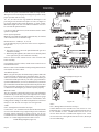
INSTALLATION INSTRUCTIONS
AND
OWNER'S MANUAL
The White Mountain Log Collection
UNVENTED GAS LOG HEATER OR
VENTED DECORATIVE APPLIANCE
MODELS
This appliance may be installed in an aftermarket
permanently located, manufactured (mobile) home,
where not prohibited by local codes.
VFSR-16C-2
VFSR-18C-2
VFSR-24C-2
VFSR-30C-2
VFSR-18RAO-2
VFSR-24RAO-2
VFSR-30RAO-2
VFSR-18RS-2
VFSR-24RS-2
VFSR-30RS-2
VFSV-16C-2
VFSV-18C-2
VFSV-24C-2
VFSV-30C-2
VFSV-18RAO-2
VFSV-24RAO-2
VFSV-30RAO-2
VFSV-18RS-2
VFSV-24RS-2
VFSV-30RS-2
This appliance is only for use with the type of gas
indicated on the rating plate. This appliance is not
convertible for use with other gases.
WARNINGS
If the information in this manual is not followed
exactly, a fire or explosion may result causing property damage, personal injury or loss of life.
–
Do not store or use gasoline or other flammable
vapors and liquids in the vicinity of this or any
other appliance.
WHAT TO DO IF YOU SMELL GAS
• Do not try to light any appliance.
• Do not touch any electrical switch; do not use
any phone in your building.
• Immediately call your gas supplier from
neighbor’s phone. Follow the gas supplier’s
instructions.
• If you cannot reach your gas supplier, call the
fire department.
–
Installation and service must be performed by
a qualified installer, service agency or the gas
supplier.
12359-4-0703
EFFECTIVE DATE
JULY 2003
This is an unvented gas-fired heater. It uses air (oxygen) from the room in which it is installed. Provisions
for adequate combustion and ventilation air must be
provided. Refer to page 7.
WARNING: If not installed, operated and maintained
in accordance with the manufacturer's instructions,
this product could expose you to substances in fuel
or from fuel combustion which can cause death or
serious illness.
WATER VAPOR: A BY-PRODUCT OF UNVENTED ROOM HEATERS
Water vapor is a by-product of gas combustion. An
unvented room heater produces approximately one
(1) ounce (30ml) of water for every 1,000 BTU's
(.3KW's) of gas input per hour. Refer to page 6.
Page 1
TABLE OF CONTENTS
Section
Page
Important Safety Information .........................................................................................................................3
Safety Information for Users of LP Gas ..........................................................................................................4
Introduction .....................................................................................................................................................5
General Information ........................................................................................................................................6
Water Vapor: By Product of Unvented Room Heaters ....................................................................................6
Provisions for Adequate Combustion and Ventilation Air ...............................................................................7
Clearances .................................................................................................................................................... 7-8
Combustible Material ......................................................................................................................................9
Fireplace Preparation .......................................................................................................................................9
Installing as a Vented Appliance ....................................................................................................................10
Before Fully Installing the Appliance ............................................................................................................10
Gas Supply .....................................................................................................................................................11
Log Placement ......................................................................................................................................... 12-13
Placement of Glowing Embers and Lava Rock .............................................................................................14
Operation Instructions/Flame Appearance ....................................................................................................15
Thermostat Operation ....................................................................................................................................15
VFSV-(16, 18, 24, 30) Lighting Instructions ................................................................................................16
VFSR-(16, 18, 24, 30) Lighting Instructions ................................................................................................17
Pilot Flame Characteristics ...................................................................................................................... 18-19
Cleaning and Servicing ..................................................................................................................................19
Wiring ...........................................................................................................................................................20
Troubleshooting .............................................................................................................................................21
Parts List ........................................................................................................................................................22
Parts View ......................................................................................................................................................23
How to Order Repair Parts ............................................................................................................................23
Service Notes .................................................................................................................................................24
Page 2
12359-4-0703
IMPORTANT SAFETY INFORMATION
• An unvented room heater having an input rating of more than
6,000 Btu per hour shall not be installed in a bathroom
• An unvented room heater having an input rating of more than
10,000 Btu per hour shall not be installed in a bedroom or
bathroom.
• Never burn solid fuels in a fireplace where a gas log set is
installed.
• Due to high temperatures, the appliance should be located out
of traffic and away from furniture and draperies.
• Do not place clothing or other flammable material on or near
the appliance.
• Children and adults should be alerted to the hazards of high
surface temperature and should stay away to avoid burns or
clothing ignition.
• Young children should be carefully supervised when they are
in the same room as the appliance.
• This unit complies with ANSI Z21.11.2b-2002 Unvented Heaters and it also complies with ANSI Z21.60b-2001 Decorative
Vented Appliances for Solid Fuel Burning Fireplaces. State
or local codes may only allow operation of this appliance in a
vented configuration. Check your state or local codes.
• Correct installation of ceramic fiber logs, proper location of
the heater and annual cleaning are necessary to avoid potential problems with sooting. Sooting, resulting from improper
installation or operation, can settle on surfaces outside the
fireplace.
• Avoid any drafts that could alter burner flame patterns. Do not
allow fans to blow directly into the fireplace. Do not place a
blower inside burn box area of firebox. Ceiling fans may create
drafts that alter burner flame patterns. Sooting and improper
burning will occur as a result of drafts.
• Periodic examination and cleaning of the venting system of
the solid-fuel burning fireplace, including frequency of such
examination and cleaning, by a qualified agency.
• The installation must conform with local codes or, in the absence of local codes, with the National Fuel Gas Code, ANSI
Z223.1 (latest edition) and to the National Electrical Code,
ANSI/NFPA70 (latest edition).
• NOTE: Installation and repair should be done by a qualified
service person. The appliance should be inspected before
use and at least annually by a qualified service person. More
frequent cleaning may be required due to excessive lint from
carpeting, bedding material, etc. It is imperative that the control
compartment, burners and circulating air passageways of the
appliance be kept clean.
• Any safety screen or guard removed for servicing an appliance
must be replaced prior to operating the appliance. Provide
adequate combustion and ventilation air.
• The flow of combustion and ventilation air MUST NOT be
obstructed.
• Provide adequate clearances around air openings into the
combustion chamber and adequate accessibility clearance for
servicing and proper operation. NEVER obstruct the front
opening of the appliance.
• An unvented room heater intended for installation in a
solid-fuel burning fireplace shall comply with the following
instructions.
• A fireplace screen must be in place when the appliance is
operating and, unless other provisions for combustion air are
provided, the screen shall have an opening(s) for introduction
of combustion air.
• Solid-fuels shall not be burned in a masonry or UL 127 factorybuilt fireplace in which an unvented room heater is installed.
• Any glass doors shall be opened when the appliance is in
operation.
• Any outside air ducts and/or ash dumps in the fireplace shall
be permanently closed at time of appliance installation.
• WARNING: Failure to keep the primary air opening(s) of the
burner(s) clean may result in sooting and property damage.
WARNING
When used without adequate combustion and ventilation air,
heater may give off CARBON MONOXIDE, an odorless,
poisonous gas.
Do not install heater until all necessary provisions are made
for combustion and ventilation air. Consult the written
instructions provided with the heater for information
concerning combustion and ventilation air. In the absence
of instructions, refer to the National Fuel Gas Code, ANSI
Z223.1, Section 5.3 or applicable local codes.
This heater is equipped with a PILOT LIGHT SAFETY
SYSTEM designed to turn off the heater if not enough fresh
air is available.
DO NOT TAMPER WITH PILOT LIGHT SAFETY
SYSTEM!
If heater shuts off, do not relight until you provide fresh air.
If heater keeps shutting off, have it serviced. Keep burner and
control compartment clean.
12359-4-0703
CARBON MONOXIDE POISONING MAY LEAD TO
DEATH.
Early signs of carbon monoxide poisoning resemble the flu,
with headache, dizziness and/or nausea. If you have these signs,
heater may not be working properly. Get fresh air at once! Have
heater serviced.
Some people – pregnant women, persons with heart or lung
disease, anemia, those under the influence of alcohol, those at
high altitudes – are more affected by carbon monoxide than
others.
The pilot light safety system senses the depletion of oxygen
at its location. If this heater is installed in a structure having a
high vertical dimension, the possibility exists that the oxygen
supply at the higher levels will be less than that at the heater. In
this type of application, a fan to circulate the structure air will
minimize this effect. The use of this fan will also improve the
comfort level in the structure. When a fan is used to circulate
air, it should be located so that the air flow is not directed at
the burner.
Page 3
SAFETY INFORMATION FOR USERS OF LP-GAS
Propane (LP-Gas) is a flammable gas which can cause fires and
explosions. In its natural state, propane is odorless and colorless.
You may not know all the following safety precautions which
can protect both you and your family from an accident. Read
them carefully now, then review them point by point with the
members of your household. Someday when there may not be
a minute to lose, everyone's safety will depend on knowing
exactly what to do. If, after reading the following information,
you feel you still need more information, please contact your
gas supplier.
LP-GAS WARNING ODOR
If a gas leak happens, you should be able to smell the gas because of the odorant put in the LP-Gas.
That's your signal to go into immediate action!
Do not operate electric switches, light matches, use your
• Use your neighbor's phone and call a trained LP-Gas service
phone. Do not do anything that could ignite the gas.
person and the fire department. Even though you may not
Get everyone out of the building, vehicle, trailer, or area.
continue to smell gas, do not turn on the gas again. Do not
Do that IMMEDIATELY.
re-enter the building, vehicle, trailer, or area.
Close all gas tank or cylinder supply valves.
• Finally, let the service man and firefighters check for escaped
LP-Gas is heavier than air and may settle in low areas such
gas. Have them air out the area before you return. Properly
as basements. When you have reason to suspect a gas leak,
trained LP-Gas service people should repair the leak, then
keep out of basements and other low areas. Stay out until
check and relight the gas appliance for you.
firefighters declare them to be safe.
•
•
•
•
NO ODOR DETECTED - ODOR FADE
Some people cannot smell well. Some people cannot smell the
odor of the chemical put into the gas. You must find out if you
can smell the odorant in propane. Smoking can decrease your
ability to smell. Being around an odor for a time can affect your
sensitivity or ability to detect that odor. Sometimes other odors
in the area mask the gas odor. People may not smell the gas odor
or their minds are on something else. Thinking about smelling
a gas odor can make it easier to smell.
The odorant in LP-gas is colorless, and it can fade under some
circumstances. For example, if there is an underground leak, the
movement of the gas through soil can filter the odorant. Odorants
in LP-Gas also are subject to oxidation. This fading can occur if
there is rust inside the storage tank or in iron gas pipes.
The odorant in escaped gas can adsorb or absorb onto or into
walls, masonry and other materials and fabrics in a room. That
will take some of the odorant out of the gas, reducing its odor
intensity.
LP-Gas may stratify in a closed area, and the odor intensity
could vary at different levels. Since it is heavier than air, there
may be more odor at lower levels. Always be sensitive to the
slightest gas odor. If you detect any odor, treat it as a serious
leak. Immediately go into action as instructed earlier.
SOME POINTS TO REMEMBER
•
Learn to recognize the odor of LP-gas. Your local LP-Gas
Dealer can give you a "Scratch and Sniff" pamphlet. Use it
to find out what the propane odor smells like. If you suspect
that your LP-Gas has a weak or abnormal odor, call your
LP-Gas Dealer.
•
If you are not qualified, do not light pilot lights, perform
service, or make adjustments to appliances on the LP-Gas
system. If you are qualified, consciously think about the
odor of LP-Gas prior to and while lighting pilot lights or
performing service or making adjustments.
•
Sometimes a basement or a closed-up house has a musty
smell that can cover up the LP-Gas odor. Do not try to light
pilot lights, perform service, or make adjustments in an area
where the conditions are such that you may not detect the
odor if there has been a leak of LP-Gas.
•
Odor fade, due to oxidation by rust or adsorption on walls
of new cylinders and tanks, is possible. Therefore, people
should be particularly alert and careful when new tanks or
cylinders are placed in service. Odor fade can occur in new
tanks, or reinstalled old tanks, if they are filled and allowed
Page 4
to set too long before refilling. Cylinders and tanks which
have been out of service for a time may develop internal rust
which will cause odor fade. If such conditions are suspected
to exist, a periodic sniff test of the gas is advisable. If you
have any question about the gas odor, call your LP-gas dealer.
A periodic sniff test of the LP-gas is a good safety measure
under any condition.
•
If, at any time, you do not smell the LP-Gas odorant and you
think you should, assume you have a leak. Then take the same
immediate action recommended above for the occasion when
you do detect the odorized LP-Gas.
•
If you experience a complete "gas out," (the container is under no vapor pressure), turn the tank valve off immediately.
If the container valve is left on, the container may draw in
some air through openings such as pilot light orifices. If this
occurs, some new internal rusting could occur. If the valve is
left open, then treat the container as a new tank. Always be
sure your container is under vapor pressure by turning it off
at the container before it goes completely empty or having
it refilled before it is completely empty.
12359-4-0703
INTRODUCTION
IMPORTANT: Read all instructions carefully before starting installation.
Failure to follow these installation instructions may result in a possible
fire hazard and will void the warranty.
Save this manual for future reference.
Please read this manual before installing and using the appliance.
Instructions to Installer
1. Installer must leave instruction manual with owner after installation.
2. Installer must have owner fill out and mail warranty card supplied with
unvented room heater/vented decorative appliance.
3. Installer should show owner how to start and operate unvented room
heater/vented decorative appliance.
Always consult your local Building Department regarding regulations,
codes or ordinances which apply to the installation of an unvented room
heater/vented decorative appliance.
This appliance may be installed in an aftermarket* manufactured (mobile)
home, where not prohibited by state or local codes.
*Aftermarket: Completion of sale, not for purpose of resale, from the
manufacturer.
This appliance is only for use with the type of gas indicated on the rating
plate. This appliance is not convertible for use with other gases.
New Installation
VFSV Model - variable does not operate-ON is OFF/OFF is ON-wires
into the back of receiver are reversed.
Solid-fuels shall not be burned in a fireplace where a vented decorative
appliance is installed.
A vented decorative appliance must be installed only in a solid-fuel
burning fireplace with a working flue and constructed of non-combustible
material.
Any alteration of the original design, installed other than as shown in these
instructions or use with a type of gas not shown on the rating plate is the
responsibility of the person and company making the change.
Important
All correspondence should refer to complete Model Number, Serial Number
and type of gas.
Attention: During initial use of ceramic log you will detect an odor as the
ceramic log is cured.
Notice: During initial firing of this unit, its paint will bake out, and smoke
will occur. To prevent triggering of smoke alarms, ventilate the room in
which the unit is installed.
WARNING: This appliance is for installation only in a solid-fuel
burning masonry or UL 127 factory-built fireplace or in a listed ventless
firebox enclosure. It has been design certified for these installations.
Exception: DO NOT install this appliance in a factory-built fireplace
that includes instructions stating it has not been tested or should not
be used with unvented gas logs.
WARNING: Any modification to this unvented gas heater or its
controls can be dangerous. Improper installation or use of the heater
can cause serious injury or death from fire, burns, explosion or carbon
monoxide poisoning.
Well Head Gas Installations
Some natural gas utilities use "well head" gas. This may affect the Btu output
of the unit. Contact the gas company for the heating value. Contact the
manufacturer or your gas company before changing spud/orifice size.
ACCESSORIES
Description
Color
For use with VFSV and VFSR models
EK-1
Embers Kit
ELH-1
Fireplace Hood for Vent-Free Logs
Black
ELH-2
Fireplace Hood for Vent-Free Logs
Brass
For use with VFSR models only
FRBC-1
Battery Operated Remote Control
FRBTC-1
Battery Operated Remote Control with Thermostat
FREC-1
Electric Remote Control
FWS-1
Wall Switch
GWSG-T
Wall Thermostat, Millivolt
PRODUCT SPECIFICATION
Natural Gas
Variable
Millivolt
Propane Gas
Variable
Millivolt
Regulator pressure setting
3.5" W.C.
3.5" W.C.
Regulator pressure setting
10.0" W.C.
10.0" W.C
Gas inlet pressure
Max. 10.5" W.C.
Min. 5.0" W.C.
Max. 10.5" W.C.
Min. 5.0" W.C.
Gas inlet pressure
Max 13.0" W.C.
Min. 11.0" W.C.
Max. 13.0" W.C.
Min. 11.0" W.C.
MODEL
GAS TYPE
VALVE TYPE
BTUH MAX. RATE
BTUH MIN. RATE
VFSV-16
Natural
Variable
25,000
17,500
VFSV-16
Propane
Variable
22,500
15,750
VFSR-16
Natural
Millivolt
25,000
17,500
VFSR-16
Propane
Millivolt
22,500
15,750
VFSV-18
Natural
Variable
32,000
19,000
VFSV-18
Propane
Variable
32,000
19,000
VFSR-18
Natrual
Millivolt
32,000
22,000
VFSR-18
Propane
Millivolt
32,000
22,000
VFSV-24
Natural
Variable
36,000
20,000
VFSV-24
Propane
Variable
36,000
20,000
VFSR-24
Natural
Millivolt
36,000
25,000
VFSR-24
Propane
Millivolt
36,000
25,000
VFSV-30
Natural
Variable
38,000
20,000
VFSV-30
Propane
Variable
38,000
20,000
12359-4-0703
Page 5
GENERAL INFORMATION
This is an unvented gas-fired heater. It uses air (oxygen) from the
room in which it is installed. Provisions for adequate combustion
and ventilation air must be provided.
Keep room area clear and free from combustible materials,
gasoline and other flammable vapors and liquids.
Unvented gas heaters are a supplemental zone heater. They are not
intended to be a primary heating appliance. Water vapor produced
by an unvented heater can create moisture problems in a home
when operated for extended periods of time.
During manufacturing, fabricating and shipping, various
components of this appliance are treated with certain oils, films or
bonding agents. These chemicals are not harmful but may produce
annoying smoke and smells as they are burned off during the initial
operation of the appliance; possibly causing headaches or eye or
lung irritation. This is a normal and temporary occurrence.
The initial break-in operation should last 2-3 hours with the burner
at the highest setting. Provide maximum ventilation by opening
windows or doors to allow odors to dissipate. Any odors remaining
after this initial break-in period will be slight and will disappear
with continued use.
This appliance must not be used with glass doors in the closed
position. This can lead to pilot outages and severe sooting outside
the fireplace.
Do not use this room heater if any part has been under water.
Immediately call a qualified service technician to inspect the
room heater and replace any part of the control system and any
gas control which has been under water.
Before you get started
Carefully inspect the contents for shipping damage. If any parts are
missing or damaged, immediately inform the dealer from whom
you purchased the appliance. Do not attempt to install any part of
the appliance unless you have all parts in good condition.
Metal shipping plate covering burner marked REMOVE must be
removed from top of burner and discarded. Burner will not operate
if plate is left in place.
Make sure you have received all parts:
Check your packing list to verify that all listed parts have been
received. You should have the following:
• Gas log grate/burner assembly.
• VFS(V,R)-(16, 18, 24, 30)C; 16", 18", 24" and 30" logs, five
(5) ceramic fiber logs.
VFS(V,R)-(18, 24, 30)RAO; 18", 24" and 30" logs, seven (7)
refractory logs.
• VFS(V,R)-(18, 24, 30)RS; 18", 24" and 30" logs, six (6)
refractory logs.
• Two (2) masonry anchoring screws and two (2) 10 x 1/2" black
sheet metal anchoring screws.
• Plastic bag containing glowing embers (rock wool) for burner
coverage.
• Plastic bag containing lava rock.
•
Millivolt controlled heater designed to be operated with optional
devices for ON/OFF functions.
• Wall switch or thermostat with wire.
• Hand held remote control with ON/OFF switch or
thermostat.
Handle the gas log burner assembly by the grate and legs only.
Do not pick the unit up by the burner.
Gloves are recommended when handling ceramic fiber logs to
prevent skin irritation from loose fibers. Logs are fragile - Handle
with care.
Qualified Installing Agency
Installation and replacement of gas piping, gas utilization equipment or accessories and repair and servicing of equipment shall
be performed only by a qualified agency. The term "qualified
agency" means any individual, firm, corporation, or company
that either in person or through a representative is engaged in and
is responsible for (a) the installation, testing, or replacement of
gas piping or (b) the connection, installation, testing, repair, or
servicing of equipment; that is experienced in such work; that is
familiar with all precautions required, and that has complied with
all the requirements of the authority having jurisdiction.
State of Massachusetts: The installation must be made by
a licensed plumber or gas fitter in the Commonwealth of
Massachusetts.
The installation must conform with local codes or, in the absence of
local codes, with the National Fuel Gas Code, ANSI Z223.1.*
*Available from the American National Standards Institute, Inc. 11 West 42nd
St., New York, N.Y. 10018.
High Altitudes: For altitudes/elevation above 2,000 feet ratings
should be reduced at the rate of 4 percent for each 1,000 feet above
sea level. Contact the manufacturer.
WATER VAPOR: A BY-PRODUCT OF UNVENTED ROOM HEATERS
Water vapor is a by-product of gas combustion. An unvented room
heater produces approximately one (1) ounce (30ml) of water for
every 1,000 BTU's (.3KW's) of gas input per hour.
Unvented room heaters are recommended as supplemental heat (a
room) rather than a primary heat source (an entire house). In most
supplemental heat applications, the water vapor does not create a
problem. In most applications, the water vapor enhances the low
humidity atmosphere experienced during cold weather.
Page 6
The following steps will help insure that water vapor does not
become a problem.
1. Be sure the heater is sized properly for the application, including ample combustion air and circulation air.
2. If high humidity is experienced, a dehumidifier may be used
to help lower the water vapor content of the air.
3. Do not use an unvented room heater as the primary heat
12359-4-0703
PROVISIONS FOR ADEQUATE COMBUSTION & VENTILATION AIR
This heater shall not be installed in a confined space unless provisions
are provided for adequate combustion and ventilation air.
The National Fuel Gas Code defines a confined space as a space whose
volume is less than 50 cubic feet per 1,000 Btu per hour (4.8m3 per kw)
of the aggregate input rating of all appliances installed in that space and
an unconfined space as a space whose volume is not less than 50 cubic
feet per 1,000 Btu per hour (4.8 m3 per kw) of the aggregate input rating
of all appliances installed in that space. Rooms communicating directly
with the space in which the appliances are installed, through openings
not furnished with doors, are considered a part of the unconfined space.
Unusually Tight Construction
The air that leaks around doors and windows may provide enough fresh
air for combustion and ventilation. However, in buildings of unusually
tight construction, you must provide additional fresh air.
Unusually tight construction is defined as construction where:
a. Walls and ceilings exposed to the outside atmosphere have a
continuous water vapor retarder with a rating of one perm or less
with openings gasketed or sealed, and
b. Weatherstripping has been added on openable windows and doors,
and
c. Caulking or sealants are applied to areas such as joints around
window and door frames, between sole plates and floors, between
wall-ceiling joints, between wall panels, at penetrations for plumbing, electrical, and gas lines, and at other openings.
If your home meets all of the three criteria above, you must provide
additional fresh air.
Warning: If the area in which the heater may be operated is smaller than
that defined as an unconfined space or if the building is of unusually tight
construction, provide adequate combustion and ventilation air by one
of the methods described in the National Fuel Gas Code, ANSI Z223.1,
Section 5.3. or applicable local codes.
Example of Large Room with 1/2 Wall divider.
Figure 1
The following formula can be used to determine the maximum heater
rating per the definition of unconfined space:
Btu/Hr =
(L1 + L2)FT x (W)FT x (H)FT
x 1000
50
If the area in which the heater may be operated is smaller than that defined
as an unconfined space, provide adequate combustion and ventilation air
by one of the methods described in the National Fuel Gas Code, ANSI
Z223.1, Section 5.3.
Adhere to all codes, or in their absence, the latest edition of THE
NATIONAL FUEL GAS CODE ANSI Z223.1 or NFPA54 which can
be obtained from:
American National Standards Institute
Inc.
11 West 42nd St.
National Fire Protection Association,
Batterymarch Park
CLEARANCES
Minimum Dimensions For Solid Fuel Burning Fireplaces UL127
Factory Built Fireplaces (Figure 2)
Model
VFSV-16
VFSR-16
VFSV-18
VFSR-18
VFSV-24
VFSR-24
VFSV-30
VFSR-30
A
18"
18"
17"
17"
23"
23"
26"
26"
B
11 1/2"
11 1/2"
14"
14"
14"
14"
14"
14"
C
24"
24"
28"
28"
30"
30"
34"
34"
D
18"
18"
17"
17"
18"
18"
20"
20"
The dimensions shown and defined in the fireplace manufacturer’s
instructions are minimum clearances to maintain in installing this
heater. Left and right clearances are determined when facing the
front of the heater.
Follow these instructions to ensure safe installation.
Failure to follow instructions exactly can create a fire hazard.
12359-4-0703
Figure 2
Page 7
CLEARANCES (continued)
Sidewall & Ceiling Clearances
18", 24", 30" Log
16" Log
(Figure 3)
Non-Combustible
Material Distance
Requirements for
Safe Installation
12" or more
Non-combustible material.
Less than 12"
Non-combustible material must be extended to
at least 8" with the installation of the optional
fireplace hood. If you cannot extend noncombustible material at least 8", you must
operate heater with flue damper open.
41"
36"
Mantel Clearances with Hood (Figure 5)
You must have non-combustible materials above the fireplace opening.
Non-combustible material must extend at least 8" above fireplace opening.
With sheet metal, you must have non-combustible material behind it.
Heat resistant materials such as slate and marble must be at least 1/2"
thick. Sheet metal should not be installed onto combustible material.
Figure 3
The sides of the fireplace opening must be 6" from any combustible wall.
The ceiling must be at least 36" (for the 16" log) and 41" (for 18", 24"
and 30" logs) from the fireplace opening.
Mantel Clearances Without Hood (Figure 4)
You must have non-combustible materials above the fireplace opening.
Non-combustible material must extend at least 12" above fireplace
opening. With sheet metal, you must have non-combustible material
behind it.
Heat resistant materials such as slate and marble must be at least 1/2"
thick. Sheet metal should not be installed onto combustible material.
10" and less
Example: A mantel may project from the wall a maximum of 2" at a minimum of 13-1/2" above the opening, and a maximum of 6" at a minimum
of 15" above the opening.
HEAT RESISTANT
MATERIAL
8" WITH HOOD
8"
6"
4"
2"
Mantel
Mantel
Mantel
Mantel
14.25"
16.0"
13.5"
15.0"
Mantel
HOOD
HEATER IN
FIREPLACE
OR FIREBOX
HEAT RESISTANT
MATERIAL
12" WITHOUT
HOOD
28"
12"
HEATER IN FIREPLACE
OR FIREBOX
Figure 5
If your installation does not meet the above minimum clearances, you
must proceed to one of the following steps:
• Operate the heater with the flue damper open. See page 10 for Installing
as a Vented Appliance.
• Raise the mantel to the proper height.
• Remove the mantel.
Floor Clearance (Figure 6)
If installing heater at floor level, the minimum distance to combustibles
is “0” inches.
Figure 6
Figure 4
If your installation does not meet the above clearances, you must proceed
to one of the following steps:
• Use a hood
• Operate the heater with flue damper open. See page 10 for Installing
as a Vented Appliance.
• Raise the mantel to the proper height.
• Remove the mantel.
Page 8
12359-4-0703
COMBUSTIBLE MATERIAL
Do not attach combustible material to the mantel of your fireplace. This
is a fire hazard.
No greeting card, stockings or ornamentation of any type should be
placedon or attached to the fireplace. This is a heating appliance. The
flow of heat can ignite combustibles.
Figure 8
Figure 7
FIREPLACE PREPARATION
• Turn off gas supply to fireplace or firebox.
• Have the fireplace floor and chimney professionally cleaned to remove
ashes, soot, creosote or other obstructions.
Have this cleaning performed annually after installation.
• Seal any fresh air vents or ash clean-out doors located on floor or wall
of fireplace. If not, drafting may cause pilot
outage or sooting. Use a heat-resistant sealant. Do not seal chimney
flue damper.
Install and operate the appliance as directed in this manual.
FOR MASONRY BUILT FIREPLACES
FREE OPENING AREA OF CHIMNEY DAMPER FOR VENTING
COMBUSTION PRODUCTS FROM DECORATIVE APPPLIANCES
FOR INSTALLATION IN SOLID FUEL BURNING FIREPLACES
Appliance Input Rate (BTU/hr)
Chimney
Height*
(ft)
6
8
10
15
20
30
FOR FACTORY BUILT FIREPLACES
FREE OPENING AREA OF CHIMNEY DAMPER FOR VENTING
COMBUSTION PRODUCTS FROM DECORATIVE APPLIANCES
FOR INSTALLATION IN SOLID FUEL BURNING FIREPLACES
Appliance Input Rate (BTU/hr)
Chimney
Height*
(ft)
10
15
20
25
30
35
40
*
**
20
30
40
Minimum Opening** (sq. in.)
11.3
8.6
7.5
6.6
6.2
5.7
5.3
16.6
12.6
10.8
9.6
9.1
8.0
7.5
22.1
17.3
14.5
12.6
11.3
10.8
10.2
20
30
40
Minimum Opening** (sq. in.)
17.6
16.5
15.1
14.1
12.9
12.2
25.7
23.7
21.7
19.9
18.5
16.9
33.8
31.2
28.7
26.1
23.7
21.6
*
Height is from hearth to top of chimney and the minimum height is
6 feet.
** Chart shows minimum opening (sq. in.) for given height and input
rate.
Height is from hearth to top of chimney and the minimum height is
10 feet.
Chart shows minimum opening (sq. in.) for given height and input
rate.
12359-4-0703
Page 9
INSTALLING AS A VENTED APPLIANCE
and National Fuel Gas Code, Section 6.6 since, the gas logs are
operated with the damper open, non-combustible material and
minimum mantel requirements do not apply.
This appliance is for installation only in a solid fuel burning
fireplace (masonry fireplace or manufactured fireplace) with a
working flue and constructed of noncombustible material.
Damper stop installation:
A damper stop must be provided with the unit. Contact your
dealer to obtain one. The damper stop must be installed as shown
in (Figure 9) to prevent full closure of the fireplace damper blade
and provide a minimum 29 square inch flue opening.
State of Massachusetts requirement for installation of vented
decorative appliance in a vented fireplace is the following:
Damper Stop Installation
Figure 9
Manual and millivolt controlled gas logs may be installed as
a vented decorative log set in compliance with ANSI Z21.60
A vented decorative gas appliance must be installed in a vented
fireplace only in the state of Massachusetts. The vent damper
must be removed or welded permanently open.
BEFORE FULLY INSTALLING THE APPLIANCE
• Turn off the gas supply to the fireplace or firebox.
• Seal any fresh air vents and/or ash clean-out doors located on
the floor or wall of the fireplace. If left unsealed, drafting may
cause pilot outage or sooting. Use a heat resistant sealant. Do
not seal the chimney flue damper.
Before installing in a solid fuel burning fireplace, the chimney
flue and firebox must be cleaned of soot, creosote, ashes and loose
paint by a qualified chimney cleaner.
You must secure the gas log heater to the fireplace floor. If
not, the entire unit may move when you adjust the controls.
Movement of unit may cause shifting of the gas logs which
leads to sooting and improper burning. Grate movement could
cause a gas leak.
Special care is required if you are installing the unit into a
sunken fireplace. You must raise the fireplace floor to allow
access to gas log controls. This will insure adequate air flow
and guard against sooting. Raise the fireplace floor using
noncombustible materials.
Assembly Procedure: (Figure 10)
1. Center the gas log unit in the fireplace or firebox. Make certain
the front feet of the grate sit inside the front edge of the
fireplace or firebox.
2. An anchor hole is provided in the two bottom side members of
the grate frame. After centering the grate correctly, mark the
hole positions on the fireplace/firebox floor. Drill two (2) 5/32"
diameter holes approximately 1-1/2" deep for masonry screws
or 1/8" hole for sheet metal screws.
3. Anchor the grate to the fireplace/firebox floor using the screws
provided. Refer to Figure10.
Proper installation of the grate is essential to prevent any movement of the gas logs and controls during operation.
Figure 10
Page 10
12359-4-0703
GAS SUPPLY
Check all local codes for requirements, especially for the size and
type of gas supply line required.
Recommended Gas Pipe Diameter
Pipe Length
(Feet)
0-10
10-40
40-100
100-150
Schedule 40 Pipe
Inside Diameter
Nat.
L.P.
1/2"
3/8"
1.3 cm
1.0 cm
1/2"
1/2"
1.3 cm
1.3 cm
1/2"
1/2"
1.3 cm
1.3 cm
3/4"
1/2"
1.9 cm
1.3 cm
Tubing, Type L
Outside Diameter
Nat.
L.P.
1/2"
3/8"
1.3 cm
1.0cm
5/8"
1/2"
1.6 cm
1.3cm
3/4"
1/2"
1.9 cm
1.3cm
7/8"
3/4"
2.2 cm
1.9cm
Note: Never use plastic pipe. Check to confirm whether your local
codes allow copper tubing or galvanized.
Note: Since some municipalities have additional local codes,
it is always best to consult your local authority and installation
code.
Installing a New Main Gas Cock
Each appliance should have its own manual gas cock.
In the state of Massachusetts the gas cock must be a T handle
type.
A manual main gas cock should be located in the vicinity of
the unit. Where none exists, or where its size or location is not
adequate, contact your local authorized installer for installation
or relocation.
Compounds used on threaded joints of gas piping shall be resistant
to the action of liquefied petroleum gases. The gas lines must be
checked for leaks by the installer. This should be done with a soap
solution watching for bubbles on all exposed connections, and if
unexposed, a pressure test should be made.
Never use an exposed flame to check for leaks. Appliance must be
disconnected from piping at inlet of control valve and pipe capped
or plugged for pressure test. Never pressure test with appliance
connected; control valve will sustain damage!
A gas valve and ground joint union should be installed in the gas
line upstream of the gas control to aid in servicing. It is required
by the National Fuel Gas Code that a drip line be installed near
the gas inlet. This should consist of a vertical length of pipe tee
connected into the gas line that is capped on the bottom in which
condensation and foreign particles may collect.
12359-4-0703
Figure 11
The use of the following gas connectors is recommended:
— ANS Z21.24 Appliance Connectors of Corrugated Metal
Tubing and Fittings
— ANS Z21.45 Assembled Flexible Appliance Connectors of
Other Than All-Metal Construction
The above connectors may be used if acceptable by the authority
having jurisdiction. The state of Massachusetts requires that a
flexible appliance connector cannot exceed three feet in length.
Pressure Testing of the Gas Supply System
1. To check the inlet pressure to the gas valve, a 1/8" (3.175mm)
N.P.T. plugged tapping, accessible for test gauge connection,
must be placed immediately upstream of the gas supply
connection to the appliance.
2. The appliance and its individual shutoff valve must be
disconnected from the gas supply piping system during any
pressure testing of that system at test pressures in excess of
1/2 psig (3.5 kPa).
3. The appliance must be isolated from the gas supply piping
system by closing its individual manual shutoff valve during
any pressure testing of the gas supply piping system at test
pressures equal to or less than 1/2 psig (3.5 kPa).
Attention! If one of the procedures results in pressures in excess
of 1/2 psig (14" w.c.) (3.5 kPa) on the appliance gas valve, it will
result in a hazardous condition.
Page 11
LOG PLACEMENT
VFSR and VFSV-(16, 18, 24, 30)C
Before you begin: This unit is supplied with a set of five ceramic
fiber logs. Do not, handle these logs with your bare hands! Always
wear gloves to prevent skin irritation from ceramic fibers. After
handling logs, wash your hands gently with soap and water to
remove any traces of fibers.
Every burner has a shipping plate on burner pan. This shipping
plate must be removed before log placement.
All Logs
The positioning of the logs is critical to the safe and clean operation
of this heater. Sooting and other problems may result if the logs
are not properly and firmly positioned in the appliance.
Refer to Figures 12 , 13, 14 and 15 for the following warning.
3. Place rear (#1) log onto right, rear pin on rear log support.
4. Place middle (#2) log between rear log support and burner
pan.
5. Place left, front (#3) log onto two (2) left, front pins on burner
pan.
6. Place right, front (#4) log onto two (2) right, front pins on
burner pan.
7. Place branch (#5) log onto two (2) pins on middle (#2) log.
Attention: On 16" log set, middle (#2) log has one (1) pin.
8. Log placement is completed.
Attention: Do not use Figure 13 to order logs. Refer to Page
22, Parts List and Page 23, Parts View to order logs for your
appropriate model number.
Warning: Failure to position the parts in accordance with this
diagram or failure to use only parts specifically approved with
this appliance may result in property damage or personal
injury.
PROPER INSTALLATION SEQUENCE:
VFSR and VFSV-(16, 18, 24, 30)C (Figures 12 and 13)
1. Remove shipping plate from burner pan.
2. Place two (2) log grates onto two (2) left, front pins and two
(2) right, front pins on burner pan.Secure grates with two (2)
Tinnerman clips.
Log Placement
VFSR and VFSV-(16, 18, 24, 30)C Logs
Figure 13
Page 12
Figure 12
12359-4-0703
PROPER INSTALLATION SEQUENCE:
VFSR and VFSV-(18, 24, 30)RAO (Figures 12 and 14)
1. Remove shipping plate from burner pan.
2. Place two (2) log grates onto two (2) left, front pins and two
(2) right, front pins on burner pan. Secure grates with two
(2) Tinnerman clips.
3. Place right, rear (#1) log onto right, rear pin on rear log
support.
4. Place left, rear (#2) log onto left, rear pin on rear log
support.
5. Place left, front (#3) log onto two (2) left, front pins on burner
pan.
6. Place right, front (#4) log onto two (2) right, front pins on
burner pan.
7. Insert boss on top, middle (#5) log into recess on right side
of left, rear (#2) log.
8. Insert boss on top, left (#6) log into recess on left side of left,
rear (#2) log and onto left side of left, front (#3) log.
9. Insert boss on top, right (#7) log into recess on right side of
right, rear (#1) log and onto right side of right, front (#4)
log.
10. Log placement is completed.
PROPER INSTALLATION SEQUENCE:
VFSR and VFSV-(18, 24, 30)RS (Figures 12 and 15)
1. Remove shipping plate from burner pan.
2. Place two (2) log grates onto two (2) left, front pins and two
(2) right, front pins on burner pan.Secure grates with two (2)
Tinnerman clips.
3. Place left rear (#1) log onto left, rear pin on rear log support.
4. Place right, rear (#2) log onto right, rear pin on rear log
support.
5. Place left, front (#3) log onto two (2) left, front pins on burner
pan.
6. Place right, front (#4) log onto two (2) right, front pins on
burner pan.
7. Insert boss on top, left (#5) log into recess on left side of left,
rear (#1) log and onto left side of left, front (#3) log.
8. Insert boss on top, right (#6) log into recess on right side of
left, front (#3) log.
9. Log placement is completed.
Attention: Do not use Figure 15 to order logs. Refer to Page
22, Parts List and Page 23, Parts View to order logs for your
appropriate model number.
Attention: Do not use Figure 14 to order logs. Refer to Page
22, Parts List and Page 23, Parts View to order logs for your
appropriate model number.
Log Placement
VFSR and VFSV-(18, 24, 30)RAO Logs
Figure 14
12359-4-0703
Log Placement
VFSR and VFSV-(18, 24, 30)RS Logs
Figure 15
Page 13
PLACEMENT OF GLOWING EMBERS AND LAVA ROCK
Provided with the log set is a small bag of glowing embers (rock
wool) to be placed between logs on the flat metal surface of the
burner.
TOP VIEW OF LOG SET
REAR LOG
Placement of Glowing Embers (rock wool)
For Refractory Sassafras (RS) Logs
Figure 18
Placement of the glowing embers (rock wool) is very individual
and light coverage of the areas indicated will provide your best
effects. We recommend separation of the rock wool by hand and
make your coverage as light and fluffy as possible.
Place just enough embers on the burner to obtain the glow and a
gold yellow flame.
Do not place embers (rock wool) over large ports in rear portion
of burner.
A thin layer of glowing embers (rock wool) should be placed under
open space between the right and left middle logs.
Rock wool should not be placed in the area of the pilot assembly.
Placement of Glowing Embers (rock wool)
For Charred Oak (C) Logs
Figure 16
Placement of Glowing Embers (rock wool)
For Refractory Aged Oak (RAO) Logs
Placing Lava Rock in Front of Grate and Burner Pan on Fireplace
Floor
Spread lava rocks on fireplace floor in front of grate and burner
pan. The lava rocks are for decorative effect and are not required
for fireplace operation.
ATTENTION: DO NOT PLACE LAVA ROCKS ON LOGS
OR ROCK WOOL. THE LAVA ROCKS SHOULD ONLY
BE PLACED ON THE FIREPLACE FLOOR.
Figure 17
Page 14
12359-4-0703
OPERATION INSTRUCTIONS/FLAME APPEARANCE
Flames from the pilot (rear right back side of the pan burner) as
well as the main flame should be visually checked as the log set
is installed.
In normal operation at full rate after 10 to 15 minutes, the flame
appearance should be sets of yellow flames.
NOTE: all flames will be random by design, flame height will
go up and down.
Glowing embers (rock wool) can cover the pan burner in between
the front and middle logs, but very little is necessary to cover this
area. Excess ember material causes the yellow flame to become
orange and stringy. Apply just enough to obtain slow glow and a
gold yellow flame.
Variable - Figure 19
Avoid any drafts that alter burner flame patterns. Do not allow
fans to blow directly into fireplace. Do not place a blower inside
the burner area of the firebox. Ceiling fans may create drafts that
alter flame patterns. Sooting and improper burning will result.
During manufacturing, fabricating and shipping, various
components of this appliance are treated with certain oils, films or
bonding agents. These chemicals are not harmful, but may produce
annoying smoke and smells as they are burned off during the initial
operation of the appliance, possibly causing headaches or eye or
lung irritation. This is a normal and temporary occurrence.
The initial break-in operation should last 2-3 hours with the burner
at the highest setting. Provide maximum ventilation by opening
windows or doors to allow odors to dissipate. Any odors remaining
after this initial break-in will be slight and will disappear with
continued use.
Millivolt - Figure 20
THERMOSTAT OPERATION
Variable Control has five (5) positions
Off – All gas to set is completely off at the valve.
Pilot – Valve position to light/maintain the standing
pilot.
Low – Minimum gas rate - pleasing yellow flames glowing embers.
High – Maximum gas rate - pleasing yellow flames glowing embers.
Ignition –
Pilot –
12359-4-0703
Piezo Ignitor allows lighting of the pilot without
matches.
All gas log heaters are designed with safety pilot
systems that will shut down when the level of
oxygen available in the room is low. The pilot
will only relight when adequate fresh air is
available.
Millivolt Control has four (4) positions
Off – All gas to set is completely off at the valve.
Pilot – Valve position to light/maintain the standing
pilot.
Low – Minimum gas rate - pleasing yellow flames glowing embers.
High – Maximum gas rate - pleasing yellow flames glowing embers.
Ignition –
Pilot –
Thermo –
Piezo Ignitor allows lighting of the pilot without
matches.
All gas log heaters are designed with safety pilot
systems that will shut down when the level of
oxygen available in the room is low. The pilot
will only relight when adequate fresh air is
available.
All millivolt logs are fitted with a thermo
Page 15
VFSV-(16, 18, 24, 30) LIGHTING INSTRUCTIONS
FOR YOUR SAFETY READ BEFORE LIGHTING
WARNING: If you do not follow these instructions exactly, a fire or explosion may result causing property damage, personal injury or loss of life.
A. This appliance has a pilot which must be lighted by hand.
When lighting the pilot, follow these instructions exactly.
department.
C. Use only your hand to push in or turn the gas control
knob. Never use tools. If the knob will not push in or
turn by hand, don't try to repair it; call a qualified service
technician. Force or attempted repair may result in a fire
or explosion.
B. BEFORE LIGHTING smell all around the appliance area
for gas. Be sure to smell next to the floor because some gas
is heavier than air and will settle on the floor.
WHAT TO DO IF YOU SMELL GAS
• Do not try to light any appliance.
• Do not touch any electrical switch;
do not use any phone in your building.
• Immediately call your gas supplier from a neighbor's
phone. Follow the gas supplier's instructions.
• If you cannot reach your gas supplier, call the fire
D. Do not use this appliance if any part has been under
water. Immediately call a qualified service technician
to inspect the appliance and to replace any part of the
control system and any gas control which has been under
water.
LIGHTING INSTRUCTIONS
to “PILOT”. A spark is produced when gas control knob
is turned between “IGN” and PILOT”. Repeatedly depress
and turn gas control knob between “IGN” and PILOT”
until pilot is ignited. Continue to hold the control knob
in for about one (1) minute after pilot is lit. Release knob
and it will pop back up. Pilot should remain lit. If it goes
out, repeat steps 2 through 7.
Note: For easy access to valve for lighting pilot, remove branch
log and middle log from burner assembly before lighting.
1. STOP! Read the safety
information.
2. Push in gas control knob
slightly and turn clockwise
to the “OFF”
position. Do not force.
• If the knob does not pop out when released, stop
and immediately call your service technician or gas
supplier.
3. Turn gas flow adjustment
knob clockwise
either manually or with
remote control to “OFF”.
• If the pilot will not stay lit after several tries, turn the gas
control knob to OFF and call your service technician.
8. Attention! Gas control has an INTERLOCK latching
device. When the pilot is initially lit and the safety magnet
is energized (pilot stays on ) the INTERLOCK latching
device becomes operative. If the gas control is turned to
the “OFF” position or gas flow to the appliance is shut
off, the pilot cannot be relighted until the safety magnet is
de-energized (approximately 60 seconds). There will be an
audible “click” when he safety magnet in the gas control
is de-energized. Pilot can now be relighted. Repeat steps
2 through 7.
4. Wait ten (10) minutes to
clear out any gas. Then
smell for gas, including
near the floor. If you smell
gas STOP! Follow “B” in
the safety information. If
you do not smell gas, go
to the next step.
5. Find pilot - the pilot is attached to rear of burner.
6. Turn gas knob counterclockwise
to “IGN”.
9. Turn gas control knob counterclockwise
“ON”.
7. Depress and turn gas control knob counterclockwise
to
10. Turn gas flow adjustment knob counterclockwise
either manually or with remote control between “OFF”
and “ON” to adjust flame height.
TO TURN OFF GAS TO APPLIANCE
1. Turn gas flow adjustment knob clockwise
manually or with remote control to “OFF”.
Page 16
either
2.
Push in gas control control knob slightly and turn clockwise
to “OFF”. Do not force.
12359-4-0703
VFSR-(16, 18, 24, 30) LIGHTING INSTRUCTIONS
FOR YOUR SAFETY READ BEFORE LIGHTING
WARNING: If you do not follow these instructions exactly, a fire or explosion may result causing property damage, personal injury or loss of life.
A. This appliance has a pilot which must be lighted by hand.
When lighting the pilot, follow these instructions exactly.
B. BEFORE LIGHTING smell all around the appliance area
for gas. Be sure to smell next to the floor because some gas
is heavier than air and will settle on the floor.
WHAT TO DO IF YOU SMELL GAS
• Do not try to light any appliance.
• Do not touch any electrical switch;
do not use any phone in your building.
• Immediately call your gas supplier from a neighbor's
phone. Follow the gas supplier's instructions.
• If you cannot reach your gas supplier, call the fire
department.
C. Use only your hand to push in or turn the gas control
knob. Never use tools. If the knob will not push in or
turn by hand, don't try to repair it; call a qualified service
technician. Force or attempted repair may result in a fire
or explosion.
D. Do not use this appliance if any part has been under
water. Immediately call a qualified service technician
to inspect the appliance and to replace any part of the
control system and any gas control which has been under
water.
LIGHTING INSTRUCTIONS
Note: For easy access to valve for lighting pilot, remove branch
log and middle log from burner assembly before lighting.
1. STOP! Read the safety information label.
2. Make sure the manual shutoff valve is fully open.
3. This gas log set is equipped with an ignition device (piezo)
which lights the pilot. If piezo ignitor does not light the pilot,
refer to Step 7.
4. Turn gas control knob clockwise
to the “OFF”
position, set the thermostat to the lowest setting and turn
ON/OFF switch to OFF position.
5. Wait ten (10) minutes to clear out any gas. Then smell for
gas, including near the floor. If you smell gas STOP! Follow
“B” in the safety information label. If you do not smell gas,
go to the next step.
6. From OFF position, turn the gas control knob counterclockwise
to “Pilot” position. Push in and hold control
knob for 5 seconds.
8.Continue pushing the control knob in for a further 60 seconds
to prevent the flame detector from shutting off the gas while
the probe is warming up. Release the control knob.
9.Turn gas control knob counterclockwise
to the “ON”
position.
10. After the pilot has been lit for one minute, the burner can
be turned on. Turn the ON/OFF switch to “ON” position or
adjust thermostat to desired setting.
11. If the gas logs will not operate, follow the instructions “To
Turn Off Gas To Appliance” and call your service technician
or gas supplier.
Wait 30 seconds before readjusting the heater when the control
knob has been turned down to a lower setting.
PIEZO
IGNITOR
HI/LO
REGULATOR
7.With the control knob pushed in, repeatedly push the piezo ignitor button until pilot is lit (or use a match to light pilot).
CONTROL
KNOB
TO TURN OFF GAS TO APPLIANCE
1. Turn control knob clockwise
completely shut off the heater.
12359-4-0703
to OFF position to
2. If applicable: Turn ON/OFF switch to OFF position and/or
set thermostat (if present) to lowest setting. If applicable:
Turn off all electric power to the heater.
Page 17
PILOT FLAME CHARACTERISTICS
Figures 21 and 24 show a correct pilot flame pattern. The correct
flame will be blue and will extend beyond the thermocouple. The
flame will surround the thermocouple just below the tip. A slight
yellow flame may occur where the pilot flame and main burner
flame meet. Figures 22 and 25 show an incorrect pilot flame pattern.
The incorrect pilot flame is not touching the thermocouple. This
will cause the thermocouple to cool. When the thermocouple
cools, the heater will shut down.
2. Blow air pressure through the holes indicated by the arrows.
This will blow out foreign materials such as dust, lint and
spider webs. Tighten nut B also by grasping nut A.
VFSR PILOT
Figure 23
VFSV PILOT
Correct appearance of pilot flame.
Figure 21
Correct Pilot Flame Pattern
Figure 24
Incorrect appearance of pilot flame.
Figure 22
If pilot flame pattern is incorrect, as shown in Figure 22
• See Troubleshooting, page 21.
Cleaning and Maintenance/Pilot
Oxygen Depletion Sensor Pilot (Figure 23 )
When the pilot has a large yellow tip flame, clean the Oxygen
Depletion Sensor as follows:
1. Clean the ODS pilot by loosening nut B from the pilot tubing.
When this procedure is required, grasp nut A with an open end
wrench.
Page 18
Incorrect Pilot Flame Pattern
Figure 25
If pilot flame pattern is incorrect, as shown in Figure 25
• See Troubleshooting, page 21.
12359-4-0703
PILOT FLAME CHARACTERISTICS (continued)
Cleaning and Maintenance/Pilot
Oxygen Depletion Sensor Pilot (Figure 26)
When the pilot has a large yellow tip flame, clean the Oxygen
Depletion Sensor as follows:
1. Clean the ODS pilot by loosening nut B from the pilot tubing.
When this procedure is required, grasp nut A with an open end
wrench.
2. Blow air pressure through the holes indicated by the arrows.
This will blow out foreign materials such as dust, lint and
spider webs. Tighten nut B also by grasping nut A.
Warning:
Never use needles, wires, or similar cylindrical objects to
clean the pilot to avoid damaging the calibrated ruby that
controls the gas flow.
Figure 26
CLEANING AND SERVICING
Annual inspection and cleaning by your dealer or qualified
service technician is recommended to prevent malfunction and/or
sooting.
TURN OFF HEATER AND ALLOW TO COOL BEFORE
CLEANING.
Remove logs, handling carefully by holding gently at each end.
Gloves are recommended to prevent skin irritation from ceramic
fibers. If skin becomes irritated, wash gently with soap and water.
Refer to manual for correct log placement.
PERIODIC CLEANING – Refer to parts diagram for location of
items discussed below.
• Do not use cleaning fluid to clean logs or any part of
heater.
• Logs - brush with soft bristle brush or vacuum with brush
attachment.
• Remove loose particles and dust from the burner areas,
controls, piezo covers and grate. Don’t remove media from
inside burner box.
• Inspect and clean burner air intake hole. Remove lint or
particles with brush. Failure to keep air intake hole clean will
result in sooting and poor combustion.
12359-4-0703
ANNUAL CLEANING/INSPECTION – Refer to parts diagram
for location of items discussed below.
•
•
•
•
•
•
Inspect and clean burner air intake hole. Remove lint or
particles with vacuum or brush. Failure to keep air intake
hole clean will result in sooting and poor combustion.
Inspect and clean all burner ports.
Inspect ODS pilot for operation and accumulation of lint at
air intake holes.
Verify flame pattern and log placement for proper
operation.
Verify smooth and responsive ignition of main burner.
Check level of ceramic media in burner. Burner should be
full, up to the level of openings in burner top.
Attention: Ceramic media that is dislodged from burner box
during shipment can be replaced through openings in burner
top. If settling of ceramic media occurs during shipment an
additional bag of ceramic media, part number, 12389 can
Page 19
WIRING
Label all wires prior to disconnection when servicing controls.
Wiring errors can cause improper and dangerous operation. Verify
proper operation after servicing.
16", 18", 24" and 30" Gas Logs (Millivolt) thermopile is self
powered gas valve and does not require 110 volts. See Figure 27
to provide optional wall switch, thermostat, or remote control.
Maximum length of 20 feet of 18 AWG to conductor wires is to
be used with all optional switches.
Use the two leads (black wires) from ON/OFF switch to attach
optional components.
Check System Operation
Millivolt system and all individual components may be checked
with a millivolt meter 0-1000 MV range.
Remote Receiver -VFSR-(16, 18, 24, 30)
Use the following steps to place the remote receiver adjacent to
the gas valve.
Attention:
1. The remote receiver can not be placed behind the gas valve
and burner assembly.
2. When facing the appliance, the remote receiver must be placed
to the right of the gas valve and burner assembly.
Note: Do not let remote control receiver come in contact with
burner assembly.
On circulating vent-free firebox, install remote control receiver
behind bottom louver.
Refer to remote control installation and operating instructions for
more details on remote control.
750 Millivolt System
When you ignite the pilot, the thermocouple produces millivolts
(electrical current) which energizes the magnet in the gas valve.
After 30 seconds to 1 minute time period you can release the gas
control knob and the pilot will stay ON. Allow your pilot flame to
operate an additional one (1) to two (2) minutes before you turn the
gas control knob from the PILOT position to the ON position. This
time period allows the millivolts (electrical current) to buildup to
a sufficient level allowing the gas control to operate properly.
Millivolt Control
The valve regulator controls the burner pressure which should be
checked at the pressure test point. Turn captured screw counter
clockwise 2 or 3 turns and then place tubing to pressure gauge
over test point (Use test point “A” closest to control knob). After
taking pressure reading, be sure and turn captured screw clockwise
firmly to re-seal. Do not over torque. Check for gas leaks.
VFSR
Note: (Wiring harness located in envelope)
Connect the 2 - 1/4" terminals onto the TH and TH/TP terminals
on valve. Place decorative log to right of the gas valve and burner
assembly. When connecting to remote receiver, cut off 1/4"
terminals from wires attached to ON/OFF switch. Strip wires back
about 1/4". Connect stripped ends into remote receiver.
VFSR Wiring Diagram (Figure 27)
Page 20
Figure 27
VFSV Wiring Diagram (Figure 28)
Figure 28
VFSV
Note: (Wiring harness located in envelope)
Connect black/red 3/16" terminal wire from receiver to 3/16"
terminal on valve. Connect black 1/4" terminal wire from receiver
to 1/4" terminal on valve. Install remote receiver cover over
receiver when receiver is installed into fireplace area. Locate
receiver and cover to the right and forward of valve. (Do not put
receiver behind logs)
12359-4-0703
TROUBLESHOOTING
SYMPTOMS - POSSIBLE CAUSES AND CORRECTIONS
Turn appliance OFF and allow to cool before servicing. Only a qualified service person should service and repair the heater.
1. When ignitor button is pressed, there is no spark at ODS/
pilot.
a. Ignitor electrode positioned wrong - Replace pilot.
b. Ignitor electrode is broken - Replace pilot.
c. Ignitor electrode not connected to ignitor cable - Reconnect
ignitor cable.
d. Ignitor cable pinched or wet. Keep ignitor cable dry - Free
ignitor cable if pinched by any metal or tubing.
e. Broken ignitor cable - Replace ignitor cable.
f. Bad piezo ignitor - Replace piezo ignitor.
2. Appliance produces unwanted odors.
a. Appliance burning vapors from paint, hair spray, glues,
etc. - Ventilate room. Stop using odor causing products
while heater is running.
b. Gas leak - Locate and correct all leaks.
3. Appliance shuts off during use. (Pilot and main burner are
off.)
a. Not enough fresh air is available for ODS/pilot to operate
- Open window and/or door for ventilation.
b. Low line pressure - Contact local gas company.
c. ODS/pilot is partially clogged - Clean ODS/pilot.
d. Defective thermocouple - Replace pilot.
4. Appliance shuts off during use. (Pilot stays on.)
a. Low line pressure - Check line pressure to the valve.
b. Defective thermopile - Check pilot flame, check wire
connections, output should be a minimum of 325 millivolts
across. TH/TP and TP terminals with ON/OFF switch
off.
5. Gas odor even when control knob is in OFF position.
a. Gas leak - Locate and correct all leaks.
b. Control valve defective - Replace control valve.
6. When ignitor button is pressed, there is spark at ODS/pilot,
but no ignition.
a. Gas supply turned off or manual shutoff valve closed
- Turn on gas supply or open manual shutoff valve.
b. Control knob not in PILOT position - Turn control knob
to PILOT position.
c. Control knob not pressed in while in PILOT position
- Press in control knob while in PILOT position.
d. Air in gas lines when installed - Continue holding down
control knob. Repeat igniting operation until air is
removed.
e. ODS/pilot is clogged - Replace ODS/pilot assembly or
get it serviced.
g. Gas regulator setting is not correct - Replace gas
regulator.
7. ODS/pilot lights but flame goes out when control knob is
released.
a. Control knob not fully pressed in - Press in control knob
fully.
b. Control knob not pressed in long enough - After ODS/pilot
lights, keep control knob pressed in 30 seconds.
8.
9.
10.
11.
12.
13.
c. Manual Shutoff valve not fully open - Fully open manual
shutoff valve.
d. Thermocouple connection loose at control valve - Hand
tighten until snug, then tighten 1/4 turn more.
e. Pilot flame not touching thermocouple, which allows
thermocouple to cool, causing pilot flame to go out. This
problem could be caused by either low gas pressure or
dirty or partially clogged ODS/pilot - Contact local gas
company.
f. Thermocouple damaged - Replace thermocouple.
h. Control valve damaged - Replace control valve.
Burner does not light after ODS/pilot is lit.
a. Burner orifice clogged - Clean burner or replace main
burner orifice.
b. Burner orifice diameter is too small - Replace burner
orifice.
c. Inlet gas pressure is too low - Contact qualified service
person.
Burner backfires during combustion.
a. Manifold pressure is too low - Contact local gas
company.
b. Burner orifice clogged - Clean burner or replace burner
orifice.
Logs appear to smoke after initial operation.
a. Vapors from paint or curing process of logs - Problem will
stop after a few hours of operation. Run the heater with
the damper open if you have one, or open a window for
the first few hours.
Log heater is intended to be smokeless. Turn OFF heater
and call qualified service person.
Heater produces a whistling noise when main burner is lit.
a. Turning control knob to HIGH position when main burner
is cold - Turn control knob to LOW position and let warm
up for a minute.
b. Air in gas line - Operate burner until air is removed from
line. Have gas line checked by local gas company.
c. Dirty or partially clogged burner orifice - Clean burner or
replace burner orifice.
No gas to pilot.
a. LP-regulator shut down due to inlet pressure too high Verify LP tank regulator is installed and set at 11" to 13"
w.c. Replace regulator on heater.
New Installation.
a. On VFSV Model variable does not operate-On is OFF/OFF
is ON-wires into the back of receiver are reversed.
If the gas quality is bad, your pilot may not stay lit, the burners may produce soot and the heater may backfire when lit. If the gas quality or pressure is
low, contact your local gas supplier immediately.
12359-4-0703
Page 21
PARTS LIST
Attention: When ordering parts, it is very important that part number and description of part coincide.
Index
No.
Part
Number
Description
COMMON PARTS
12348
BURNER ASSEMBLY (16) LP
12347
BURNER ASSEMBLY (16) NAT
12330
BURNER ASSEMBLY (18) LP
12329
BURNER ASSEMBLY (18) NAT
12321
BURNER ASSEMBLY (24) LP
12320
BURNER ASSEMBLY (24) NAT
12339
BURNER ASSEMBLY (30) LP
12338
BURNER ASSEMBLY (30) NAT
11285
BURNER SUPPORT - LEFT (16)
11376
BURNER SUPPORT - LEFT (18,24,30)
R-5676
AIR SHUTTER - NAT
R-5675
AIR SHUTTER - LP
P-204
ORIFICE - LP (16)
P-256
ORIFICE - NAT (16)
P-250
ORIFICE - LP (18)
P-243
ORIFICE - NAT (18)
P-245
ORIFICE - LP (24)
P-244
ORIFICE - NAT (24)
P-249
ORIFICE - LP (30)
P-211
ORIFICE - NAT (30)
P-200
ORIFICE FITTING
11273
GRATE (2 REQ’D) (16)
11370
GRATE (2 REQ’D) (18)
11371
GRATE (2 REQ’D) (24,30)
12328
SHIPPING PLATE (18)
11497
SHIPPING PLATE (24)
11498
SHIPPING PLATE (30)
11538
REAR LOG SUPPORT (16)
11539
REAR LOG SUPPORT (18)
11540
REAR LOG SUPPORT (24)
11541
REAR LOG SUPPORT (30)
11291
TUBING - VALVE TO BURNER
CERAMIC MEDIA
12389
11549
ROCK WOOL (16)
11548
ROCK WOOL (18)
11548
ROCK WOOL (24,30) (2 REQ’D)
11788
DECORATIVE ROCK (2 REQ’D)
11833
PILOT SHIELD - NATURAL
3
3
3
3
3
3
3
3
4
4
5
5
6
6
6
6
6
6
6
6
7
9
9
9
10
10
10
11
11
11
11
NS
NS
NS
NS
NS
NS
NS
NS
NS
MILLIVOLT SYSTEM
R-4323
GAS VALVE NATURAL
R-4324
GAS VALVE LPG
11286
BURNER SUPPORT - RIGHT (16)
11375
BURNER SUPPORT - RIGHT (18,24,30)
R-3624
PILOT NAT
R-3623
PILOT LP
11292
TUBING - VALVE TO PILOT
R-5668
IGNITOR WIRE
R-5910
SWITCH LOG ASSEMBLY
(INCLUDES SWITCH AND WIRE)
R-5757
OFF/ON SWITCH
R-5699
WIRE HARNESS
1
1
2
2
8
8
NS
VARIABLE SYSTEM
R-5672
GAS VALVE NATURAL
R-5673
GAS VALVE LPG
11333
BURNER SUPPORT - RIGHT (16)
11308
BURNER SUPPORT - RIGHT (18,24,30)
R-5170
PILOT LP
R-5171
PILOT NAT
11335
TUBING - VALVE TO PILOT
1
1
2
2
8
8
NS
NS
NS
Index
No.
Part
Number
Description
NS
R-5797
REMOTE KIT
12
12
12
13 a
13 a
13 a
13 b
13 b
13 b
14
14
14
15
16
REFRACTORY SASSAFRAS
R-6369
RIGHT FRONT LOG (18)
R-6376
RIGHT FRONT LOG (24)
R-6381
RIGHT FRONT LOG (30)
R-6371
RIGHT REAR LOG (18)
R-6378
RIGHT REAR LOG (24)
R-6383
RIGHT REAR LOG (30)
R-6368
LEFT FRONT LOG (18)
R-6375
LEFT FRONT LOG (24)
R-6380
LEFT FRONT LOG (30)
R-6370
LEFT REAR LOG (18)
R-6377
LEFT REAR LOG (24)
R-6382
LEFT REAR LOG (30)
R-6373
RIGHT BRANCH
R-6372
LEFT BRANCH
17
17
17
17
18
18
18
18
19
19
19
19
20
20
20
20
21
21
21
21
CHARRED OAK LOGS
R-5719
RIGHT FRONT LOG (16)
R-5725
RIGHT FRONT LOG (18)
R-5731
RIGHT FRONT LOG (24)
R-5737
RIGHT FRONT LOG (30)
R-5718
LEFT FRONT LOG (16)
R-5724
LEFT FRONT LOG (18)
R-6391
LEFT FRONT LOG (24)
R-5736
LEFT FRONT LOG (30)
R-5720
MIDDLE LOG (16)
R-5726
MIDDLE LOG (18)
R-5732
MIDDLE LOG (24)
R-5738
MIDDLE LOG (30)
R-5722
BRANCH LOG (16)
R-5728
BRANCH LOG (18)
R-5734
BRANCH LOG (24)
R-5740
BRANCH LOG (30)
R-5721
REAR LOG (16)
R-5727
REAR LOG (18)
R-6392
REAR LOG (24)
R-5739
REAR LOG (30)
22
22
22
23
23
23
24
24
24
25
25
25
26
26
27
27
28
REFRACTORY AGED OAK LOGS
R-6081
LEFT FRONT LOG (18)
R-6073
LEFT FRONT LOG (24)
R-6088
LEFT FRONT LOG (30)
R-6083
RIGHT FRONT LOG (18)
R-6075
RIGHT FRONT LOG (24)
R-6090
RIGHT FRONT LOG (30)
R-6080
LEFT REAR LOG (18)
R-6072
LEFT REAR LOG (24)
R-6087
LEFT REAR LOG (30)
R-6082
RIGHT REAR LOG (18)
R-6074
RIGHT REAR LOG (24)
R-6089
RIGHT REAR LOG (30)
R-6084
TOP LEFT LOG (18)
R-6076
TOP LEFT LOG (24 AND 30)
R-6085
TOP MIDDLE LOG (18)
R-6077
TOP MIDDLE LOG (24 AND 30)
R-6078
TOP RIGHT LOG (18, 24 AND 30)
USE ONLY MANUFACTURER'S REPLACEMENT PARTS. USE OF ANY OTHER PARTS COULD CAUSE INJURY OR DEATH.
Page 22
12359-4-0703
PARTS VIEW
HOW TO ORDER REPAIR PARTS
Parts can be ordered only through your service person or dealer. For best results, the service person or dealer should order parts through the distributor.
Parts can be shipped directly to the service person/dealer.
All parts listed in the Parts List have a Part Number. When ordering parts, first obtain the Model Number from the name plate on your equipment. Then
determine the Part Number (not the Index Number) and the Description of each part from the following appropriate illustration and list. Be sure to give
all this information . . .
Applaince Model Number
Part Description
Appliance Serial Number
Part Number
Type of Gas (Propane or Natural)
Do not order bolts, screws, washers or nuts. They are standard hardware items and can be purchased at any local hardware store.
Shipments contingent upon strikes, fires and all causes beyond our control.
Empire Comfort Systems, Inc. Nine Eighteen Freeburg Ave. Belleville, Illinois 62222-0529
12359-4-0703
Page 23
SERVICE NOTES
Empire Comfort Systems, Inc.
Nine Eighteen Freeburg Ave.
Belleville, Illinois 62220-2623
Page 24
PH: 1-800-851-3153
FAX: 1-800-443-8648
E-MAIL: [email protected]
WEB SITE: www.empirecomfort.com
12359-4-0703