1
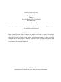
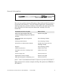
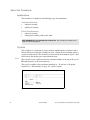
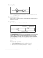
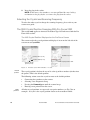
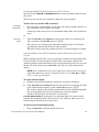
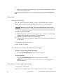
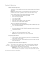
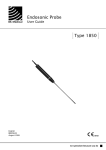
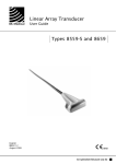
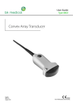
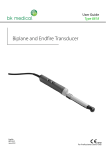
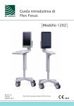
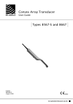
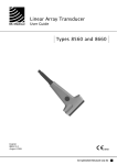
Anorectal Transducer
User Guide
Type 2050 and Type 2052
English
BB1804-B
December 2009
WORLD HEADQUARTERS
Mileparken 34
DK-2730 Herlev
Denmark
Tel.:+45 44528100 / Fax:+45 44528199
www.bkmed.com
Email: [email protected]
If you have comments about the user documentation, please write to us at the email address above.
We would like to hear from you.
BK Medical Customer Satisfaction
Input from our customers helps us improve our products and services. As part of our customer
satisfaction program, we contact a sample of our customers a few months after they receive their
orders. If you receive an email message from us asking for your feedback, we hope you will be
willing to answer some questions about your experience buying and using our products. Your
opinions are important to us. You are of course always welcome to contact us via your BK Medical
representative or by contacting us directly.
© 2009 BK Medical
Information in this document may be subject to change without notice.
Contents
General Information . . . . . . . . . . . . . . . . . . . . . . . . . . . . . . . . . . . . . . . . . . . . . . . . 5
About the Transducer . . . . . . . . . . . . . . . . . . . . . . . . . . . . . . . . . . . . . . . . . . . . . .
Applications . . . . . . . . . . . . . . . . . . . . . . . . . . . . . . . . . . . . . . . . . . . . . . .
Crystals . . . . . . . . . . . . . . . . . . . . . . . . . . . . . . . . . . . . . . . . . . . . . . . . . . .
Scanning Plane . . . . . . . . . . . . . . . . . . . . . . . . . . . . . . . . . . . . . . . . . . . . .
Scanning Frequencies . . . . . . . . . . . . . . . . . . . . . . . . . . . . . . . . . . . . . . . .
Control Buttons. . . . . . . . . . . . . . . . . . . . . . . . . . . . . . . . . . . . . . . . . . . . .
6
6
6
7
7
7
Safety Information . . . . . . . . . . . . . . . . . . . . . . . . . . . . . . . . . . . . . . . . . . . . . . . . . 8
Cleaning and Disinfection . . . . . . . . . . . . . . . . . . . . . . . . . . . . . . . . . . . . 8
Preparing the Transducer for Scanning. . . . . . . . . . . . . . . . . . . . . . . . . . . . . . . . 8
Checking Before Use . . . . . . . . . . . . . . . . . . . . . . . . . . . . . . . . . . . . . . . . 8
Using a Transducer Cover . . . . . . . . . . . . . . . . . . . . . . . . . . . . . . . . . . . . 9
Connecting the Transducer. . . . . . . . . . . . . . . . . . . . . . . . . . . . . . . . . . . . 9
Selecting the Crystal and Scanning Frequency . . . . . . . . . . . . . . . . . . . 10
The 2052 Crystal Position Scanning With Pro Focus 2202 . . . . . . . . . . 10
Scanning . . . . . . . . . . . . . . . . . . . . . . . . . . . . . . . . . . . . . . . . . . . . . . . . . . . . . . . . 12
Image Orientation . . . . . . . . . . . . . . . . . . . . . . . . . . . . . . . . . . . . . . . . . . 12
Scanning, Freezing and Capturing an Image . . . . . . . . . . . . . . . . . . . . . 12
Endoanal or Transvaginal Scanning . . . . . . . . . . . . . . . . . . . . . . . . . . . . . . . . . 12
Endorectal Scanning . . . . . . . . . . . . . . . . . . . . . . . . . . . . . . . . . . . . . . . . . . . . . .
Water Standoff System. . . . . . . . . . . . . . . . . . . . . . . . . . . . . . . . . . . . . .
Preparing the Patient. . . . . . . . . . . . . . . . . . . . . . . . . . . . . . . . . . . . . . . .
Preparing the Water Standoff System . . . . . . . . . . . . . . . . . . . . . . . . . .
Using a Rectosigmoidoscope and Scanning. . . . . . . . . . . . . . . . . . . . . .
13
13
13
13
16
3D Scanning . . . . . . . . . . . . . . . . . . . . . . . . . . . . . . . . . . . . . . . . . . . . . . . . . . . . . 19
Service and Repair . . . . . . . . . . . . . . . . . . . . . . . . . . . . . . . . . . . . . . . . . 20
English source version
BB1804-B
3
4
General Information
Figure 1. Anorectal transducers types 2050 and 2052.
This is the user guide for Anorectal Transducers Types 2050 and 2052. It contains a
description of the transducers, a list of the intended applications, and information
about operating these particular transducers. You must use this guide together with
other documents that contain important information, including vital safety
information.
Information not in this user guide
Where to find it
How to use the transducer with your
scanner, including setting up user-defined
functions
Scanner user guide
Safety information and caring for the
transducer
Care, Cleaning & Safety
Cleaning and disinfection
Care, Cleaning & Safety
Disinfectants and disinfection methods
Product Data sheet and Care,
Cleaning & Safety
Disposal
Care, Cleaning & Safety
Product specifications
Product Data sheet
Available accessories, including sterile
covers
Product Data sheet
Acoustic output data
Technical Data CD
Explanation of acoustic output
Scanner user guide
EMC (electromagnetic compatibility) data
Technical Data CD
Table 1.
Where to find additional information essential to the operation of this transducer.
When connected, the transducer complies with Type B requirements of EN60601-1
(IEC 60601-1).
Anorectal Transducers 2050 and 2052 User Guide (BB1804-B)
December 2009
5
About the Transducer
Applications
The transducer is suitable for the following types of examinations.
Colorectal Scanning
• endoanal scanning
• endorectal scanning
Pelvic Floor Scanning
• endoanal scanning
• endovaginal scanning of the pelvic floor
FDA WARNING for the United States of America The transducer should not be
used for fetal examinations.
Crystals
The transducer is a mechanical (single-element) multifrequency transducer with a
built-in 3D mover. Inside the transducer head is a double crystal assembly where 2
crystals sit back to back. The assembly can rotate inside the transducer to give a 360º
field of view. No moving parts contact human tissue.
H or L
The selected crystal is indicated after the transducer number at the top of the screen:
H (high-frequency) or L (low-frequency).
The crystal assembly can be positioned manually or – if you have a 3D option
installed (see “3D Scanning” on page 19) – by the scanner.
60mm
0mm
(fully in)
Default position
-60mm
(fully out)
Figure 2. Movement of the crystal assembly inside the transducer head.
6
December 2009
Anorectal Transducers 2050 and 2052 User Guide
Scanning Plane
360°
Figure 3. Scanning plane for the anorectal transducer. The extreme positions of the crystal
assembly are shown.
Scanning Frequencies
Each crystal has 3 scanning frequencies. On the scanner, the scanning frequency is
displayed on the screen.
Control Buttons
The transducer has 3 control buttons on the handle.
Forward (In) button
Backward (Out) button
Start/Stop/Capture button
Figure 4. Transducer control buttons.
The Start/Stop/Capture button on the underside of the handle is used to start or stop
scanning. You can specify a user-defined function for a long press (at least one
second) on the button: by default, a long press captures the current scanned image.
The Crystal Position buttons (Forward and Backward) on the upper side move the
crystal assembly.
Beeps
The scanner emits “beeps” when:
•
•
The Start/Stop/Capture button on the transducer is pressed.
The crystal arrives at its default position (0mm – see Fig 2).
Anorectal Transducers 2050 and 2052 User Guide (BB1804-B)
7
Safety Information
WARNING Always keep the exposure level (the acoustic output level and the exposure
time) as low as possible.
WARNING If at any time the scanner malfunctions, or the image is severely distorted
or degraded, or you suspect in any way that the scanner is not functioning correctly:
•
Remove all transducers from contact with the patient.
•
Turn off the scanner. Unplug the scanner from the wall and make sure it cannot be
used until it has been checked.
•
Do not remove the scanner cover.
•
Contact your BK Medical representative or hospital technician.
Contact your BK Medical representative if you believe the correct functioning of any
BK Medical equipment is impaired in any way.
Cleaning and Disinfection
A transducer used for endocavity procedures with no puncture must be cleaned
immediately after use and disinfected before it is used. You must use a transducer
cover. See Care, Cleaning & Safety.
WARNING Users of this equipment have an obligation and responsibility to provide
the highest degree of infection control possible to patients, co-workers and themselves.
To avoid cross contamination, follow all infection control policies for personnel and
equipment established for your office, department or hospital.
Caution: Keep all plugs and sockets absolutely dry at all times.
A list of disinfectants and disinfection methods that the transducer can withstand are
listed in the Product Data sheet and Care, Cleaning & Safety.
Preparing the Transducer for Scanning
All equipment must be cleaned and disinfected before use.
Checking Before Use
The transducer may be damaged during use or processing, so it must be checked
before use. Check the transducer more thoroughly once a month. See Care, Cleaning
& Safety. Contact your BK Medical service representative if you detect any signs of
damage or of oil leaking from the transducer.
WARNING Do not use the transducer if you detect any signs of damage.
8
December 2009
Anorectal Transducers 2050 and 2052 User Guide
Using a Transducer Cover
Endoanal or Transvaginal Scanning
You must use a transducer cover. See the Product Data sheet for a list of available
transducer covers, including sterile covers.
Apply scanning gel or other water-soluble agent inside and outside the cover to create
good acoustic contact.
Water-soluble
gels only
Latex
WARNING Use only water-based gel (sterile if you are using a sterile transducer
cover). Products containing parabens, petroleum or mineral oils may harm the
transducer or transducer cover.
WARNING Because of reports of severe allergic reactions to medical devices
containing latex (natural rubber), FDA is advising health-care professionals to identify
their latex-sensitive patients and be prepared to treat allergic reactions promptly.
To put on the cover:
1
Apply gel to the tip of the transducer so that it covers the entire scanning surface
(most of the black part of the transducer). You can also put scanning gel inside
the tip of the cover before you put the cover over the transducer.
Make sure that there is enough scanning gel to cover the entire front end of the
transducer (the black part of the transducer). This prevents image artifacts
caused by air bubbles.
2
Pull the transducer cover over the transducer.
Before scanning, apply a small amount of gel to the outside of the transducer
cover to create good acoustic contact between the patient and the transducer.
Re-apply the gel frequently to ensure good screen images.
3
4
Endorectal Scanning
You must use a water-standoff system (with a water standoff condom) to image the
rectum from the anorectal junction and further into the rectum. See page 13.
Connecting the Transducer
WARNING Keep all plugs and sockets absolutely dry at all times.
To connect the transducer:
1
2
If the connector plug cover (used to protect the plug during cleaning and
disinfection) is screwed on, unscrew it to remove it.
Align the red arrow on the connector plug with the red dot on the transducer
socket.
Anorectal Transducers 2050 and 2052 User Guide (BB1804-B)
9
3
Insert the plug in the socket.
NOTE: To disconnect the transducer, you must pull back the outer locking
mechanism on the plug before you remove the plug from the socket.
Selecting the Crystal and Scanning Frequency
To select the other crystal or change the scanning frequency, please refer to your
scanner user guide.
The 2052 Crystal Position Scanning With Pro Focus 2202
This section only applies to Anorectal Transducer Type 2052 when used with the Pro
Focus 2202 scanner.
The 2052 Crystal Position Displayed on the Pro Focus Screen
The scanner tracks the crystal position and displays it in cm on the left side of the
screen next to Crystal Pos.
destination position
crystal position (in cm)
insertion depth (in cm)
crystal position slider
anatomic (body)
position (in cm)
Figure 5. Position of the 2052 transducer crystal.
Default
position
The crystal position is 0 when the crystal is at the tip of the transducer (farthest into
the patient). This is the default position.
The following actions cause the crystal to move to the default position:
•
•
•
•
Other
positions
10
Connecting the transducer to the scanner.
Selecting a new Diagnostic Setup.
Pressing the Forward button until the scanner beeps.
Entering a new patient ID on the screen.
All other crystal positions are expressed as negative numbers (see Fig 5 for an
example). -6.0 (cm) is the crystal position closest to the transducer handle.
December 2009
Anorectal Transducers 2050 and 2052 User Guide
Changing the 2052 Crystal Position on the Pro Focus
You can use the Forward and Backward buttons on the transducer handle to move
the crystal.
You can also use the on-screen control to change the crystal position.
To move the crystal in the 2052 transducer:
Transducer
control button
•
Press one of the control buttons on the upper side of the transducer handle (see
Fig 4) until the crystal is where you want it.
A short press moves the crystal. As you hold the button down, the crystal moves
faster.
or
On-screen
control
•
Click Crystal Pos under General on the left side of the screen and drag the
slider (or point at Crystal Pos and press [ +/- ]).
The value you set is displayed in italic font to indicate that it is the desired
(destination) position rather than the actual position.
When the crystal reaches the position you have set, the font changes to normal.
Insertion Depth of the 2052 Transducer and Anatomic Position of the
Crystal
When scanning with the 2052, you can specify the transducer insertion depth (how
far the transducer is inserted into the rectum). The scanner then calculates the
anatomic position (depth in the body) of the crystal and displays that, too, in cm on
the left side of the screen next to Anat. Pos. (See Fig 5 to see the format of the
display.)
NOTE: If the combination of insertion depth and crystal position results in an
impossible anatomic position, the displayed value next to Anat. Pos. is NA/y,
where y is the insertion depth.
To set the insertion depth:
Find the actual insertion depth by reading the scale on the transducer.
2 Click Anat. Pos under General on the left side of the screen and drag the slider
to the actual insertion depth (or point at Anat. Pos and press [ +/- ]).
The scanner calculates the anatomic position based on the insertion depth and
the crystal position (note that crystal position is a negative number):
Anatomic Position=Insertion Depth+Crystal Position.
Insertion Depth Not Set If you do not set an insertion depth, the scanner cannot
calculate the anatomic position. There may be cases, however, where you set an
insertion depth and then do not want to use it.
1
To remove the insertion depth setting:
•
Drag the Anat. Pos. (insertion depth) slider to 0.
Anorectal Transducers 2050 and 2052 User Guide (BB1804-B)
11
or
•
Make sure the image is frozen, and press the transducer control button to move
the insertion depth to zero.
If the insertion depth is not set, or is zero, the displayed value next to Anat. Pos. is
NA.
Scanning
Image Orientation
The 12 o’clock position on the displayed image is identified by the two control
buttons on the transducer handle pointing to the anterior 12 o’clock position.
WARNING Before you start scanning, verify the orientation of both crystals in the
transducer.
To verify crystal orientation:
1
2
3
Hold the transducer in the 12 o’clock position, that is, with the 2 control buttons
on the handle pointing to the anterior 12 o’clock position.
Touch the tip of the transducer with your finger.
Verify that the image of your finger is displayed at the top of the image displayed
on the screen
Changing the Image Orientation
See the scanner user guide.
Scanning, Freezing and Capturing an Image
To start or stop scanning (freeze the image):
•
Press the Start/Stop/Capture button (see Fig 4) briefly.
To copy the image:
•
Press the Start/Stop/Capture button for more than one second.
NOTE: Your scanner may be set up so that a long press on the button has a
different function.
Endoanal or Transvaginal Scanning
Preparing the Transducer
You must use a transducer cover. (See “Using a Transducer Cover” on page 9.)
12
December 2009
Anorectal Transducers 2050 and 2052 User Guide
Endorectal Scanning
Water Standoff System
You must use a water standoff system to scan the rectum from the anorectal junction
and beyond.
BK Medical recommends using a rectosigmoidoscope when attempting to scan
proximally in the rectum (approximately 10cm or more from the anal verge).
A water standoff system with the following components is available:
• Water standoff collar UA0671 with O-ring UA0674
• Plastic extension tube UA0676
• 2-way stopcock UA0677
• Plastic syringe UA0678
• Light cable adaptor UA0682, reusable (for UA0681)
• Non-sterile water standoff condoms UA0037
and one of the following rectosigmoidoscopes:
•
Rectosigmoidoscope kit UA0672 (DO0164 compatible with Welch Allyn® light
source, with obturator DO0163)
or
•
Rectosigmoidoscope kit UA0673 (DO0165 compatible with Storz® light source,
with obturator DO0163)
or
•
Single-use, sterile Rectosigmoidoscope kit UA0681
NOTE: See the Product Data sheet for ordering information.
Preparing the Patient
1
2
Always perform a digital palpation before you insert a rectosigmoidoscope or
endo transducer into the rectum.
Give the patient an enema – liquid should be held retained as long as possible
before being expelled.
Preparing the Water Standoff System
Disinfect
before using
The transducer, water standoff collar, O-ring, rectosigmoidoscope and obturator
must be cleaned and disinfected before use. The water standoff collar, O-ring,
rectosigmoidoscope and obturator can be autoclaved.
NOTE: For best results, separate the O-ring from the water standoff collar
before autoclaving. O-rings that are no longer watertight should be replaced.
Anorectal Transducers 2050 and 2052 User Guide (BB1804-B)
13
To prepare the water standoff system:
1
Place the two O-rings in the outer grooves as shown in this picture.
The water outlet is just above the
inner groove. Do NOT block this
Place the O-rings in
these two grooves
Luer Lock valve
(water inlet)
2
3
Use a little water to moisten the silicone O-rings inside the water standoff collar.
Gently slide the water standoff collar over the transducer.
Make sure that the marker on the water standoff collar is aligned with the marker
on the transducer.
align the two markers
two markers aligned
water standoff
collar
4
14
Pull a water standoff condom over the transducer, attaching it to the groove on
the water standoff collar. Check the water standoff condom for tears.
December 2009
Anorectal Transducers 2050 and 2052 User Guide
wire clip
2-3 silicone rubber bands in
each of the two grooves
5
6
Secure the water standoff condom in place with 2 or more silicone rubber bands
in each groove (silicone rubber bands are supplied with water standoff condoms
UA0037).
Fill the syringe with degassed water. Use the 2-way stopcock and plastic
extension tube to attach the syringe to the Luer lock valve on the water standoff
collar.
Luer lock valve
Fill the water standoff condom with approximately 50ml of degassed water.
Air bubbles may appear in the water standoff condom. You must remove the air
bubbles to avoid artifacts on the ultrasound image.
7
8
Hold the transducer with the water standoff condom pointing downwards and
use the syringe to draw off as much air as possible.
Anorectal Transducers 2050 and 2052 User Guide (BB1804-B)
15
Refill the water standoff condom with degassed water. Repeat this procedure
until there is no air left in the water standoff condom.
10 Remove enough water from the water standoff condom to allow the setup to pass
through the BK Medical rectosigmoidoscope.
11 Lubricate the entire outer surface of the water standoff condom with a glycerinebased lubricant, such as UA0675.
9
Caution: You must lubricate the condom before you insert the setup into the
rectosigmoidoscope. The lubricant must be glycerine-based.
The transducer is designed to pass through Rectosigmoidoscope UA0672,
Rectosigmoidoscope UA0673 or single-use Rectosigmoidoscope UA0681.
Caution: If you use a rectosigmoidoscope that you do not purchase from BK Medical,
it must be fully cylindrical and have an inner diameter of at least 21 mm.
The transducer is now prepared for an endorectal examination.
Caution: You MUST lubricate the outer surface of the water standoff condom before you
introduce the transducer with a water standoff system into a rectosigmoidoscope.
Without lubrication you may not be able to retract the transducer from the
rectosigmoidoscope. This can damage the transducer.
Caution: If the transducer cannot be withdrawn from the rectosigmoidoscope, contact
your BK Medical representative immediately.
Using a Rectosigmoidoscope and Scanning
The patient is examined in the left lateral decubitus or the dorsal lithotomy position.
Follow policies established for your office, department or hospital for the use of a
rectosigmoidoscope.
To perform an endorectal examination:
1
2
16
Prepare the water standoff system before you start. (See “Preparing the Patient”
on page 13.)
Always perform a digital palpation before you insert a rectosigmoidoscope or
endo transducer into the rectum.
December 2009
Anorectal Transducers 2050 and 2052 User Guide
Using a rectosigmoidoscope
3 Insert the obturator fully into the rectosigmoidoscope and apply gel to the
outside tip.
4 Introduce the rectosigmoidoscope as far as the beginning of the rectal ampulla
(4–5 cm).
WARNING Do not use excessive force during insertion. Do not make excessive lateral
movements during or after insertion. Risk of injury or tissue damage to the patient
could occur under certain circumstances.
5
6
7
Slowly remove the obturator.
Use the light source and visually inspect the rectum. If necessary, empty the
rectum.
Using visual guidance, advance the rectosigmoidoscope to the level of interest
– so that it just covers the area you want to scan.
WARNING If you advance the rectosigmoidoscope any further into the rectum, you
must do it under visual guidance using the conventional techniques that are approved
at your hospital.
Anorectal Transducers 2050 and 2052 User Guide (BB1804-B)
17
Inserting the transducer and water standoff system
8 Make sure that the entire outer surface of the water standoff condom is
thoroughly lubricated with a glycerine-based lubricant.
9 Insert the transducer just until the tip of the transducer is at the far end of the
rectosigmoidoscope.
The end of the rectosigmoidoscope nearest you will be at the 200 mm mark on the
transducer if you are using either the UA0672 or UA0673 rectosigmoidoscope. If you
are using the single-use rectosigmoidoscope UA0681 then it will be at the 220 mm
mark.
WARNING Never advance the transducer/rectosigmoidoscope combination beyond
the level identified by introducing the rectosigmoidoscope under visual guidance.
10 Hold the transducer in position and pull the rectosigmoidoscope slowly back
toward yourself until the rim touches the water standoff collar UA0671.
NOTE: It is important to hold collar and rectoscope tight together.
11 Click the wire clip over the rectosigmoidoscope to hold it in place with the water
standoff collar. Do not reposition the transducer relative to the patient while you
are doing this.
click the wire clip
over the
rectosigmoidoscope
wire clip
rectosigmoidoscope
18
December 2009
Anorectal Transducers 2050 and 2052 User Guide
Scanning
12 To start scanning, press the Start/Stop/Capture button on the underside of the
transducer handle. Scan the exposed area. (For a 3D scan, see “3D Scanning” on
page 19.)
13 If you have not scanned the entire object of interest in the first pass, pull the
transducer together with the rectosigmoidoscope back another 4–6 cm, and scan
again.
Removing the transducer from the patient
14 When you have completed the examination, empty the water from the water
standoff condom, using a syringe.
15 Release the wire clip from the rectosigmoidoscope. Withdraw the transducer.
16 Then withdraw the rectosigmoidoscope.
Clean immediately after use
If biological materials are allowed to dry on the transducer or attachments,
disinfection and sterilization processes may not be effective. Therefore, you must
clean attachments and transducers immediately after use.
Use a suitable brush to make sure that biological material and gel are removed from
all channels and grooves, including the collar and wire clip attachment. See Care,
Cleaning & Safety for cleaning and disinfection instructions.
3D Scanning
To acquire a 3D dataset, you must have the 3D option installed on your scanner: this
includes the necessary software and hardware as well as a 3D license.
To acquire a 3D dataset:
•
See the scanner user guide for instructions.
NOTE: The maximum length of a dataset acquired using this transducer is
60mm. The resolution of the dataset is never worse than 0.5mm (i.e. 2 images
per 1mm of movement). The default resolution is 0.25mm.
Anorectal Transducers 2050 and 2052 User Guide (BB1804-B)
19
Transducer Support Collar UA0679
Figure 6. The support collar on the transducer without and with a fixation clamp.
Caution: It is strongly recommended that you use the transducer support collar to
reinforce the transducer handle when you use a fixation device (such as the variable
friction support arm UA0553) to hold the transducer in place.
Slide the collar over the handle of the transducer and clamp it in place.
Then with the variable friction support arm, you can either:
•
Clamp the instrument fixation clamp to the support collar.
or
•
Remove the fixation clamp from a support arm and screw the support collar
directly to the arm, using the threaded hole at the end of the steel ball joint piece.
Disinfection and Sterilization The transducer support collar can be autoclaved.
Service and Repair
WARNING Service and repair of BK Medical electromedical equipment must be
carried out only by the manufacturer or its authorized representatives. BK Medical
reserves the right to disclaim all responsibility, including but not limited to responsibility
for the operating safety, reliability and performance of equipment serviced or repaired
by other parties. After service or repairs have been carried out, a qualified electrical
engineer or hospital technician should verify the safety of all equipment.
20
December 2009
Anorectal Transducers 2050 and 2052 User Guide