1
Foreword
ADVICE
This User’s Manual clearly defines the agreement between CHERY Automobile Co., Ltd. and its
customers on the product quality assurance, and the establishment and termination of rights and
bligations on after-sales service. Please carefully read this User’s Manual before using the parts
manufactured by the CHERY Company.
User’s Munual for CHERY QQ3
You are sincerely congratulated to be an owner of CHERY QQ3! Thank you for your belief for Chery Automobile Co., Ltd and your choi ce
for Chery products!
You will receive the high quality services from Chery Authorized Sales and Service Station whose employees have been trained well and
specially.
State-of-art technology offers CHERY QQ3 the excellent performance. Selecting CHERY QQ3 shows that you have very high
requireements on the performance and style of a vehicle.
Prior to using this car, please carefully read this User’s M anual because the information hereto enables you to know how to properly
manipulate and maintain this vehicle, and get the maximum enjoy able driving experience.
This User’s M anual is applied to the CHERY QQ3 only.
Chery Automobile Co., LTD
1
Foreword
This manualis compiled in accordance
with the structural features of QQ3
manufactured by CHERY Automobile Co.,
Ltd.. This manual is applied to the QQ3.
This manual covers the latest information
until it is printed. Chery Automobile Co.,
Ltd. is fully responsible for the revision
and explanation of this manual and
reserves the right of changing products
without further notice. Some pictures in
the manual are the schemes only for
references, and in the case of
unconformity
between objects and
pictures, the objects will dominate.
This manual is the principal evidence, on
which you can get the automobile quality
guarantee and initial maintenance free of
charge, and it should be placed in your
vehicle so that it is available whenever it is
needed. In the event that you want to sell
your vehicle, please hand over the manual
and complete set of documents together
with the vehicle to the new owner so that
the new owner for their use at necessary
moment.
Important Declaration
Before operating the products, please
carefully read the M anual, which your
rights for enjoy services of warranty from
our corporation are lost due to the
violation of the operational provisions.
CHERY Autombile Co., Ltd (hereinafter
refer to as “the Company” or “CHERY
Company ”) has established the technical
maintenance specifications of different
phases and the running-in of new vehicle,
including the maintenance on initial 5,000
km. The maintenance an care specified
above are crucial for your vehicle safety
and maintaining fine running conditions,
so please abide by without violation.
In the event that your vehicle or its parts
fail in the function due to misuse,
negligence, improper operation, and
maintenance that not in line with the
prescribed interval of mileage/running
hour, or signing the name or sealing on the
maintenance evidence as required, or
refitting /adding equipment on the vehicle
without approval, you will lose the right of
claiming, and any direct or indirect
application for services of warranty will be
refused by the Chery authorized sales and
service station.
In case that abnormality occurs to your
vehicle during the operation, it must be
overhauled and maintained by the Chery
authorized sales and service station, and
during the overhauling and maintenance
the Chery authorized sales and service
station has the right to decide whether to
maintain the vehicle through the method
of repairing or replacing identical part or
component depending on condition of the
vehicle.
If you are confused during reading the
manual, Chery company and Chery
authorized sales and service station will
explain to you in detail, and at the same
time precious opinions are welcome from
our customers.
WISH YOU A HAPPY DRIVING!
The copyright of this manual belongs to
the CHERY Automobile Co., Ltd.
2
Brief Introduction
Chapter 1
Introduction
Brief
3
Brief Introduction
Prior to reading this
instruction manual, you
should learn about the
following:
Thank you for your purchasing a
Chery vehicle. To help you use your
car properly and ensure your benefit,
please take time to read this manual
carefully.
This
manual
contains
some
important information for daily
operation and normal maintenance.
It is designed to assist you to be
familiar with operation of your car.
Thorough familiarity with your
vehicle will provide you enhanced
security, lower cost and enjoyable
driving experience.
Any improper operation might cause
your vehicle damage, and you might
lose your right to claim.
installation
Regular
your
future or to certain market, hence, some
vehicle in good condition and play a
items in this manual may be inapp licable
significant role in maintaining and the
to your vehicle.
resale value of your vehicle. And many
maintenance will keep
skillful auto repair technicians from Chery
for
QQ3
model.
Some
equipment may be only supplied in the
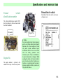
Warning Symbols In
This Manual
Authorized Service Stations nationwide
can provide you high quality repair or
maintenance service. Chery Authorized
Service Stations are also the reliable
sources for providing genuine spare parts
from the original manufacturer.
When using a vehicle, how to
minimize the damage to vehicle and its
equipment as well as prevent from
passenger’s injury? In this manual, the
answers are cont ained in the explanations
marked with triangle warning symbol.
SCOPE OF EQUIPMENT
This manual specifies the utmost scop e of
Please read it carefully and abide by
relating cont ents.
would-be installed equipment for QQ3
Equipment marked with asterisk
series vehicles until printing this manual,
only are used for certain models,
i.e., all of the standard and optional
or only supplied for options for some kind
4
Brief Introduction
of models, or only supplied in certain
above-mentioned information.
complete the purchase.
market.
If you see this symbol in your
vehicle, prior to any operations,
you must read the relating chapters in this
manual.
S afety and environmental protection
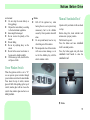
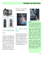
Inspection of a New
Vehicle
Owing to machining and assembling
Prior to hand over the vehicle to you, the
errors, the frictional resistance between the
dealer of Chery Automobile has already
moving parts of a new vehicle will be
carried out inspection in accordance with
much larger than normal condition at the
the provision specified by Chery Company.
initial stage. The running-in effect of the
The dealer should fill in the date of vehicle
initial stage has considerable influences on
our
delivery in the “Vehicle Delivery and
the vehicle’s service life, operational
obligatory responsibilities and
Inspection Record”, and stamp his official
reliability, and economy. So the using of a
obligations in the effort of
seal of specific dealer.
new vehicle must strictly comply with
We
environmental
must
shoulder
protection.
It
is
an
important procedure to properly use a
vehicle and dispose wasted cleaning
articles as well as lubricants in accordance
with relating regulations so as to achieve
this goal. In this manual, arboraceous
symbol
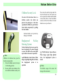
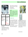
Running-In of a New
Vehicle
is
used
to
highlight
the
The dealer will check the performance of
an entire car in accordance with “Vehicle
Sales
and
Automobile",
Delivery
and
Card
introduce
of
Chery
common
knowledge of using the vehicle, then the
specifications on running-in.
Specification of
Within 1,000 Km:
Running
is
Full
speed
in
absolutely
impermissible;
sales clerk and user sign their names to
5
Brief Introduction
In general, it shall not exceed 100km
the red indication area, it must switch into
necessary. Under such circumstance, when
/ h;
the adjacent high gear.
driving during the first 100 km, it ought to
Each gear shall avoid running at full
Unnecessary high speed of engine should
throttle.
be avoided. Change up as soon as possible
Specification of Running in
within the Range of 1,000 - 1,500
KM:
be relatively slow, and the driver should be
extraordinarily cautious.
is favorable for fuel saving, work noise
Running-in for the new friction lining of
decrease
brake is also quite necessary. When
as
well
as
environm ental
pollution reduction.
It can gradually increase to the
However, engine speed should not be too
maximum speed or run at the
slow when cruise, only when the engine is
maximum allowable speed of the
overloaded should it is necessary to shift
engine.
down.
driving during the first 200 km, ideal
friction of the brake is not available. In
this phase, if the braking is comparatively
poor, the driver can conduct properly
larger pedal pressure. This action is also
app licable to the newly replaced brake
Attentions Should be Paid after
the Period of Running In:
When a vehicle is cold, no matter whether
certain gear, the engine should not work at
When driving a vehicle with speed meter,
friction lining.
it is on neutral position or driving on
maximum speed.
the allowable maximum transient speed is
After 800 km of cruise, the wheel nut of a
new vehicle must be again screwed down
to specified torque. Refer to the chapter
When manually shift the
When using a new tire, at the beginning it
"Specification Parameters" in this manual
gear, if the cursor of speedometer reaches
has no optimal adhesive force. Hence,
for proper torque value. Similarly, if a
6000 r/min.
running-in for first-life tire is also quite
6
Brief Introduction
wheel is replaced or a wheel nut has ever
been loosened, after 800 km of cruise, the
wheel nut should be again screwed down
according to specified torque value.
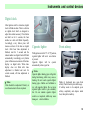
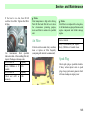
One-to-One Service
To provide better vehicle services as well
as app lication, a Chery vehicle dealer will
appoint one service consultant for you
when you purchase a car. If you have any
problems during the process of driving,
please contact your consultant, who will
provide you with high quality services.
7
Brief Introduction
Vehicle Delivery and Inspection Record:
This vehicle's delivery inspection has been
finished in accordance with the provision
specified by Chery Company Limited, and the
quality conforms to the technical specification
of Chery Company. And the certification is
presented herein.
Date of vehicle delivery:_________________
Registration
number:
Owner
_________________
Name(unit)
_________________
Address
_________________
Service Station
________________
_________________
_________________
M anager of the service station
________________
Seal of Dealer:
Telephone __________ Telephone ____________
8
Brief Introduction
Date of Vehicle Delivery:
Seal of dealer
Vehicle Model
Body VIN number
Engine No.
Transmission No
9
Brief Introduction
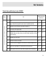
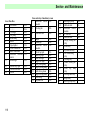
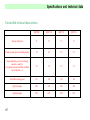
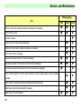
Vehicle Sales and Devlivery Card of CHERY
Performance of Complete Vehicle
Category
S/N
Item
Whether inspected and
clarified or not
No
□
□
No
□
□
No
□
No
□
□
No
□
Yes
□
No
□
Speedometer, tachometer, and odometer.
Yes
□
No
□
8
Wheel house, spare tyre in luggage boot, tool box and User’s M anual for complete vehicle.
Yes
□
No
□
9
Seat belt, seat, cigarette lighter, A/C switch and duct, glove box and sun visor.
Yes
□
No
□
10
Window regulator, rearview mirror, wiper, washer, horn/speaker, radio (CD) and antenna
Yes
□
No
□
1
Engine
Yes
2
Engine oil, brake fluid, steering fluid, coolant, electrolyte, windshield washer fluid
Yes
3
Identifications such as VIN number, engine number, nameplate, etc.
Yes
4
Locks and keys of the complete vehicle
Yes
5
Lighting system of the entire vehicle includes headlamp, directional signals, fog lamp,
combination light, interior light, stop lamp, reverse light, taillight, reading light, door lamp
and instrument light.
Yes
6
Windshield glass and body finish
7
□
□
10
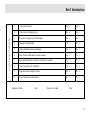
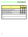
Common Sense of Application
Brief Introduction
1
93# gasoline for fuel
Yes
□
No □
2
Proper use in running-in period
Yes
□
No
□
3
Operation of complete set of vehicle lights
Yes
□
No
□
4
M eanings of warning light.
Yes
□
No
□
Yes
□
No
□
5
Prop er maintenance time and mileage
6
Items of vehicle maintenance in winter/summer
Yes
□
No
□
7
Proper understanding on cooling system and use of coolant
Yes
□
No
□
8
Proper operation of air conditioner
Yes
□
No
□
9
Precautions while starting the vehicle
Yes
□
No
□
10
Proper operation of audio devices
Yes
□
No
□
Signature of seller:
Date:
Signature of owner:
Date:
11
Brief Introduction
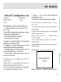
“One-to-One” Consulting Service Card
Date of Purchase:
M odel:
The following items shall be confirmed by the owner.
II. Introduction of “one-to-one” consulting service mode ("
√" for
yes and"×" for no)
□Always contact your service consultant if the owner has any
problem or requirement, while not someone else
□The service consultant is the only person who is designated by
the service station to communicate with the owner
III. Introduction of service consultant's main work ( "√" for yes
and "×" for no)
□
□ Service and reception of repair and maintenance requirement
Accept complaints
□ Regular maintenance reminding and return visit □Consulting and
solutions for repair/maintenance
□Regular greeting return visit
□Repair/maintenance
reservation accepting
□ Service activities reminding and return visit □ Annual review
reminding/accepting
□Significant festivals greeting □M iscellaneous items handling of
owner's requirement
IV. Establishment of “one-to-one" consulting service relation
Bus iness card of service
consultant
Signature of owner / date:
Signature of service consultant/ date:
12
Reserved by Service Station
I. Confirmation of matters of concern when delivery (“
√” for yes
and “×” for no)
□ Basic methods of application has been introduced, vehicle has
been inspected face to face when d elivery
□ Warranty service regulation has been clarified
□ Notices of driving have been clarified
□The significance of regular maintenance as well as maintenance
time/ mileage intervals has been clarified
□The significance of accepting maintenance /service in Chery
Authorized Service Station has been acknowledged.
□ "M aintenance M anual" and "Instruction M anual" have been
delivered, and reminded the owner to read carefully
□ Usage and function of Chery Company's customer service hot
line have been acknow ledged
□ "one-to-one ": only one service consultant shoulders the
responsibility of one owner
□ If not satisfied, owner can select another service consultant
First sheet
Owner’s name:
Dealer of Sale Service:
VIN No.
Brief Introduction
“One-to-One” Consulting Service Card
Date of Purchase:
M odel:
The following items shall be confirmed by the owner.
II. Introduction of “one-to-one” consulting service mode ("
√" for
yes and"×" for no)
□Always contact your service consultant if the owner has any
problem or requirement, while not someone else
□The service consultant is the only person who is designated by
the service station to communicate with the owner
III. Introduction of service consultant's main work ( "√" for yes
and "×" for no)
□ Service and reception of repair and maintenance requ irement□
Accept complaints
□ Regular maintenance reminding and return visit □Consulting and
solutions for repair/maintenance
□Regular greeting return visit
□Repair/maintenance
reservation accepting
□ Service activities reminding and return visit□ Annual review
reminding/accepting
□Significant festivals greeting □M iscellaneous items handling of
owner's requirement
IV. Establishment of “one-to-one" consulting service relation
Reserved by
I. Confirmation of matters of concern when delivery (“
√” for yes
and “×” for no)
□ Basic methods of application has been introduced, vehicle has
been inspected face to face when d elivery
□ Warranty service regulation has been clarified
□ Notices of driving have been clarified
□The significance of regular maintenance as well as maintenance
time/ mileage intervals has been clarified
□The significance of accepting maintenance /service in Chery
Authorized Service Station has been acknowledged.
□ "M aintenance M anual" and "Instruction M anual" have been
delivered, and reminded the owner to read carefully
□ Usage and function of Chery Company's customer service hot
line have been acknow ledged
□ "one-to-one ": only one service consultant shoulders the
responsibility of one owner
□ If not satisfied, owner can select another service consultant
Second sheet
Owner’s name:
Dealer of Sale Service:
VIN No.
Bus iness card of service
consultant
Signature of owner / date:
Signature of service consultant/ date:
13
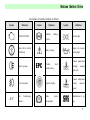
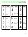
Notices Before Drive
Description of Common Symbols on Vehicle
S ymbol
Definition
CHECK ENGINE
Glass Drive Switch
Prohibitted
Rear Fog Lamp
S ymbol
Definition
Antilock
S ymbol
braking
system
Position light
Engine oil pressure
Safety warning
Throttle
Definition
warning light
fault
indicator lamp
Coolant temperature
overhigh
warning
light (red)
Coolant temperature
Front Fog Lamp
Cigarette Lighter
normal
indicator
(green)
A/C
Air
System
Conditioning
Brake
warning light
system
Identification of
air
bag
5
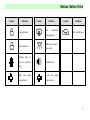
Notices Before Drive
S ymbol
Definition
Battery
Hazard
S ymbol
warning
brake
Air
bag
Horn
Vehicle maintenance
Battery positive
Headlamp switch
Definition
Windshield washing
flasher
Low beam
indicator light
Definition
Seat belt ready
High beam
Parking
S ymbol
indicator
fault
Windshield
indicator light
defrosting/defogging
Fuel level low
Inner circulating air
6
Notices Before Drive
S ymbol
Definition
S ymbol
Rear
Lockup indicator
light
windshield
heating indicator
S ymbol
Definition
Outer circulating air
Indicator for interior
Unlock indicator
Warning
Definition
lamp switch
for
door and trunk lid
Audible alarm
op en
Right
turn
lamp indicator
signal
Left
turn
signal
lamp indicator
7
Notices Before Drive
Notices Before Drive
8
Notices Before Drive
9
Notices Before Drive
Operations in the phase of
test-drive
engine, but also increase fuel and
oil consumption and even damage
engine components. And especially
try to avoid stepping down
accelerator pedal to the end under
bottom gear.
Some simple protective measures should be
followed during the initial running-in period
which can improve drivability and
economy of the vehicle and prolong its
service life.
Before entering the car
Do not run engine in high speed at
idle;
Do not overload engine possibly
while us ing transmission drive;
Avoid using emergency brake
unless there is an emergency;
Avoid stepping down accelerator at
neutral during start;
The engine requires a period of
time for warming-up after start
Avoid drawing other cars;
Avoid any rigor operations such as
emergent start, sudden acceleration
and long-time high speed running
which will not only do harm to the
Inspect if windows, outside
rearview mirror and lamps is clean
or damaged;
Inspect if tire pressure is normal;
Inspect if all vehicle lights are
normal;
Watch if there is any obstacles
behind the car;
Inspect if fuel pipes leak
Inspect if engine oil level and
other fluid level are within
standard range.
Before driving
M ake sure that you have known the
condition and equipments of the
vehicle, and how to operate them
safely.
Adjust the position of the seat;
Adjust the angle of interior and
outside mirrors on the car.
Insure that all passengers have tied
up their seat belt.
When turning the ignition switch to
position II, you should inspect
whether the alarm lights have gone
out after automatic detection.
!Notice
Please inspect if windows,
rear windshield,
all
lamps,
signal
transmission system and
warning indicator are
normal. Do not put
anything on rear luggage
10
Notices Before Drive
rack, or it will limit the
back line of sight and
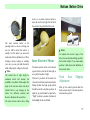
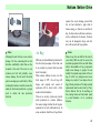
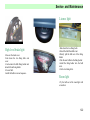
Keys
Equip two keys adapted to all
lockholes on the car, and one of them
is a spare key. Key code card of the
key is pasted on the number cap. Do
not leave code card in the car for car’s
safety. Put it at a safe place an d
remember key code. Do not record key
code in the car to prevent anyone who
got this code to copy the key without
permission.
!Notice
Do not leave the key in the car.
1. Lock the car.
2. Take the key with you.
hurt the passengers by
the movement of luggage
while emergent stopping
or shocking.
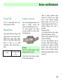
Key No.
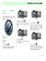
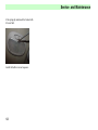
Locks
You can open and lock the front door
from outside with the equipped key.
Rotate the key counterclockwise to open
the d oo r and cl o ckwis e t o cl os e it .
!Notice
Before leaving your car, ensure all of the
doors and rear compartment lid have been
locked when there is no one to take
charge it.
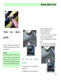
You can lock or open the door with the
lock button on the side of the windows.
Except the left-front door, you can lock
all of the doors from outside by pressing
the lock button and closing the door.
When you leave the car, you can only
lock the left front door from outside with
the key.
Lock
Unlock
11
Notices Before Drive
can pull the inner handle.
Unlock
Lock
When opening the door from outside, you
can pull the outer handle.
When opening the door from inside, you
simultaneously.
!Notice
Before leaving the car, lock the left-front
door when there is no one to take charge.
!Notice
Do not leave children or animals alone in
the car. 1.To prevent asphyxiation
especially in hot seasons.
2.They may move the car unexpectedly.
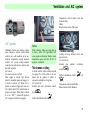
Central Control Lock
Central control lock is controlled by
the driver side door (left-front door).
When locking or opening the driver
door (left-front door) with key or
pressing the lock button, all the doors
can
be
locked
or
opened
12
Notices Before Drive
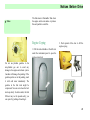
Children Security Lock
On each of the back door there is a
children security lock which can
prevent the passengers at the back,
especially the children to open the door
from inside unexpectedly by pulling
the inner h andle.
has been locked so as to prevent any
damage to the handle.
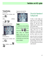
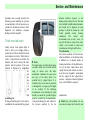
Burglarproof
Entering System
Unlock
No-Key
No-Key Entering System can open the
door in a distance of 6 meters through
a sensor. The LBD on the sensor lights
up to indicate the sensor in operation.
!Notice
Children at the backseat may open the
back door unexpectedly.
1. M ove the children security lock pin
to the locking position.
2. Do not pull the inner handle of the
door when the children security lock
Press down the metal lock pin under the
lock of each back door, then the door can
not be opened from inside and the handle
is also locked, that is, when the children
security lock has been locked, the inner
handle can not open the door.
1、LOCK button: Lock all doors. When
danger signal light has glittered 3 times,
the burglarproof system is in
operation.
Lock
2、UNLOCK button: Open all doors.
When danger signal light glittered
twice, the burglarproof system is
closed.
!Notice
The effective range of the sensor will
change with environment.
13
Notices Before Drive
Activating door Lock and
Burglarproof Mode
Close all the windows;
Turn ignition key to B, and pull
out the key;
Let all passengers get off the car.
Relief of Door Lock and
Burglarproof Mode
Press UNLOCK button on the sensor
to unlock all doors and hazard
warning lamp glitters twice at the same
time, burglarproof mode is exited.
Close all doors and hoods and
trunk lid.
Press down the LOCK button on
the sensor so as to lock all of the
doors. Those cars equipped with
power window lifting system will
automatically raise all windows,
and at the same time hazard
warning lamp glitters 3 times and
the burglarproof mode is started.
period of time.
Replace a Panasonic CR2032 battery (or
other equivalent 3V battery) in following
process:
Insert a screwdriver into the gap
between the sensor cover and
separate the 2 covers of the sensor.
Normal status: If there is not
interruption and fault, hazard-warning
lamp will glitter twice, and the interval
between each glitter is 0.5 sec.
Replace Sensor Battery:
Sensor indicator lamp does not glitter,
which means that battery needs to be
replaced, but sensor can still be used for a
If the ignition switch is set on II,
the burglarproof mode does not
work but the function of locking
still work normally.
!Notice
If you use key to lock the door, the
burglarproof mode can not be activated.
Please use sensor if you want to activate
that mode.
Pull the sensor power supply out of
the cover and disconnect the
attachments carefully and p ut it at a
clean p lace.
Install new battery, make sure that
the polarity is correctly placed
(cathode facing bottom)
Install the attachments and put the
sensor power supply into the cover.
Close the two covers of sensor.
Check whether the sensor can work
properly.
Battery
Insert a screwdriver into the gap
between the sensor covers and
separate them.
!Notice
The waste Li-battery will do harm to the
14
Notices Before Drive
environment:
Do not drop the waste battery as
living garbage;
Dispose the waste battery according
to the local reclaim regulations.
Sensor might be damaged
Do not reverse the polarity of the
sensor
Prevent falling
Do not lay anything heavy on the
sensor
Do not let the sensor touch water or
be exposed to straight sunlight
If the sensor get wet, clean it with a
soft piece of cloth
!Notice
Pull off the ignition key when
leaving the car so as to prevent any
unnecessary hurt to the children
caused by their operation when left
alone.
Do not spread hands, head or any
other thing out of the window.
The unexpected close of the window
will cause serious damage, so do
not let the children play with the
electric window switch.
Manual Sunshade-Roof
Operate with your hands to tilt sun shade
roof up.
Before doing this, check whether roof
antenna is at a proper position.
Pull forward to open it.
Press the button and raise sunshade
roof to an ideal position.
Press the button again and pull down
sunshade roof handle to close the
sunshade roof.
Power Window Switch
When the ignition switch is set to “II”,
we can operate power window through
power window switch on the inner handle.
Press down the top of switch, window
glass will fall. while pulling up the top of
switch, window glass will rise. Loose the
switch when window glass reaches to an
ideal position.
!Notice
15
Notices Before Drive
The sun shading top can not open when
there is sundries on it.
Clean the top before open it.
Eliminate the water drops, snow,
ice and sands before opening the
sun shading top.
Do not place anything heave on the
sun shading top or around. Please
close the sun shading when leaving
the car alone.
Outer Rearview Mirror
Adjust the outer rearview mirror to see
both sides of the road clearly and confirm
the position of the things you saw. Move
the outer rearview mirror to an ideal
position (for the movable lens) or use
adjustment button (for the joystick)
directly so as to adjust the angle of the
mirror.
16
Notices Before Drive
closer, so use inner rearview mirror to
clear the rear line of sight. Do not block
the rearview range from the driver seat.
The outer rearview mirror at the
passenger side is a convex, so things you
see in it will be closer than what it is
actually. Use this mirror you can watch
much wide of the road behind you. When
entering a narrow roadway or washing
your cars, you can push back the mirror
which will properly collapse to the body.
!Notice
The around line of sight might be
weakened which will increase the
possibility of accidents. Please adjust the
angle of the rearview mirror and check
whether there is any damage on the
mirror. Use defroster, atomizer and
blower to eliminate the ice and frost.
The outer rearview mirror shows thing
Inner Rearview Mirror
The inner rearview mirror can be moved
up and down as well as left and right so
as to get the best line of sight.
There are 2 positions for the inner rear
view mirror which are daytime and night.
During daytime the high speed joystick
should be moved to daytime position. At
night the joystick should be adjusted to
“Night ” position to weaken the beam of
the headlight of the cars behind.
!Notice
To maintain the rearview range of the
driver, choose daytime and high speed for
the best line of sight. If you choose night
position, it will decrease the definition of
the rearview mirror.
Front
Seat
Adjustment
Slipping
Draw up the control joystick under the
front seat and slip it to an ideal position,
then loose the joystick.
17
Notices Before Drive
anything under the seat which will
disturb the seat adjustment organ.
danger of hurting the cervix. You can
adjust its altitude by pulling up or press
down it.
Front Seat Tilt Adjustment
Pull up the joystick at the side of the seat
to adjust the backrest to an ideal angle,
and then loose the joystick.
!Notice
Do not adjust the driver seat during
driving so as to prevent the car to be out
of control.
The looseness of the seat belt will
reduce its protection function.
Adjust the front seats before tying
the seat belt.
Do
not
leave
!Notice
Do not adjust the backrest when driving.
Do not tilt the seat too much to prevent
the seat belt slide. Adjust the backrest to a
vertical angle for max protection
functions.
Headrest
!Notice
The headrest is to prevent any hurt. Do
not drive before adjusting it. Adjust its
altitude so that the back of the head can
touch the middle part of the headrest.
After the adjustment, fix the position of
the headrest. Please make sure the
headrest has been adjusted and fixed to
the right position before drive.
The headrest is designed to decrease the
Disassembly the headrest:
Pull the headrest up to the highest
position.
Insert a small screwdriver into the
18
Notices Before Drive
notch of the left guide bushing.
Touch the head of the stop perch
with the screwdriver and pull the
headrest out from the bushing.
Folding process:
Lift the seat cushion to vertical.
Pull up the lock button on the seat
backrest, loose the backrest, and
fold in the direction of front and
down.
If you want the seat backrest get
back to the vertical position, just
Folding Backseat Backrest
Fold down the backrest to increase the
space of the trunk.
pull up the backrest and pull the
backrest t o t he proper position.
If you want the cushion back to the
original position, just put it to a
proper position and pull and press
to the lock position.
!Notice
Do not pile any goods on the back
seat because it may cause damage
when the goods moving.
Notice when the backseat get back
to the vertical position:
1. Checks whether the seat backrest
and seat cushion have been locked at
a firm position by pushing or
pulling.
2. Ensure that the seatbelt is not
twisted or stuck in the seat backrest,
and p lace it at a proper position.
19
Notices Before Drive
Seat Belt
Measure
Precaution
To protect the passenger, the entire
passenger must correctly use seatbelt
during driving. One seatbelt for only one
person, and those children under 6 years
old are not suitable to use seatbelt, and
you should assembly proper child seat or
assistant cushion for your child.
!Notice
Passengers may get hurt in a collision or
emergent stop, so they must use seatbelt
at anytime. Do not use one belt by several
people. Do not put anything hard or
fragile in the pocket or clothes clinging to
the seatbelt. Misusage of the seatbelt will
cause serious damage. Do not change the
seatbelt or attach any equipment which
will affect the employment of the seatbelt.
The worn seatbelt cannot be used any
more which will probably affect the
safety of the peop le.
When using a seatbelt, please use it and
maintain the belt and child protection
system with correct method in order to
decrease the damage to the peop le in a
collision or emergent stop.
!Notice
M isusage of the seatbelt may cause
damage or even death to people. The
seatbelt should be firm and the seat
backrest should be adjusted to vertical.
Do not lean on the backrest when driving
the car. Do not use it if the belt twisted.
Do not tie the belt cross down the arm
which should be at the middle of the
shoulder, and also do not wrap it around
the head or neck. Tie it clinging to the
buttocks but not waist. If the seatbelt tied
too loosely, it will increase the rate of
hurt to people because the body will slide
under a loose belt. The loose button of
the seat belt should face outside. Insert
the pin of the belt into the appointed
connection lock. Do not put anything at
the shield board hatch of the seatbelt to
prevent it from getting stuck. If it gets
stuck, the only way is to entangle the
entire belt into the reel and then pull the
ideal length out according to the need.
Maintenance of the Seat
Belt
The seat belt should be maintained clean
and dry, avoiding any pollution by
polishing composition, oil, chemical,
especially by the acid of the accumulator.
Please wash with litmusless soap. Do not
blanch or dye the belt which will
probably do harm to the belt. Prevent the
seat belt from any sharp-edged things.
Check the belt regularly for any damage
and replace those worn ones in time. The
over strained belt should be replaced after
an accident. Chery suggests replacing all
the components of the seatbelt after a
collision. But after a slight collision, if
the Chery Service Station does not check
out any damage, and all the components
can work normally, there is no need to
replace. If there is any damage or false
with the seat belt and its components
which has not been used in an accident,
they also need to be tested and replaced if
necessary.
20
Notices Before Drive
!Notice
The worn seat belt may
cause serious damage, so check the
seat belt components regularly.
After a collis ion, you must take all
the seat belt components to the
Chery Service Station for a check
and replace them according to the
need. If the belt has been damaged
or polluted, it must be replaced.
After a serious collision, the seat
belt components must be replaced
no matter there is evident damage
or not. If the seat belt is not suitable,
it will arouse much more serious
damage. Do not change seatbelt at
will.
For pregnant woman
Suggest the pregnant woman to refer to
the doctors for the usage before using the
seatbelt.
!Notice
In order to avoid any damage to the
pregnant woman and the infant during the
travel, please use “three points on the
cross” connected seatbelt if possible and
tie it as low as possible to cross the entire
pregnant position (refer to the doctor).
Children
System
Protection
Be sure to use proper children protection
system when bringing any infants or
children.
The children protection system should be
assembled on the seat according to the
height and weight of the child.
Status shows that proper children
protection system will be safer if it is
assembled on the back seat rather than
the front seat.
!Notice
Infants and children should be kept in the
children protection system. Do not
assemble
the
backward
children
protection system on the front seat with
air bag.
Please assemble the children protection
system on the back seat as possible as
you can. If it must be assembled on the
front passenger seat, the seat should be
adjusted back as possible.
!Notice
Assemble the children protection
system according to the instruction
provided by the manufacturer.
Tie is firmly or remove it when
there is no use.
Do not hold your child in arm when
riding on the car.
If the children protection system is too
small for your child, just let him or her sit
on the back seat and tie up the seat belt. If
the child sit at the position with crossed
seat belt, and the belt is close to his or her
face or neck, you should move the child
to the middle, that is lean to the inner part
of the belt, and put your child at a place
without crossed seat belt if possible.
If the children protection system is
assembled on the front seat, child will
probably be seriously hurt when the air
bag charged and inflated.
21
Notices Before Drive
Three point seat belt
There is three points seat belt with brake
limit on every Chery car. Although the
spring-plugged seat belt is coop erated
well, the body is permitted to move freely
during a smooth running.
There is a sensitive reel on the seat belt
which is used to lock the seat belt in
violent acceleration and deceleration.
Please do not test the lock of the seat belt
by rush forward forcibly. This kind of
seat belt does not need to adjust the
length which will automatically adjust
according to the movement of the
passenger. But it will automatically lock
to limit the movement of the body of the
passenger in a sudden collision or
impulsion.
!Notice
If it gets stuck, the only way is to
entangle the entire belt into the reel and
then pull the ideal length out according to
the need.
①
②
Using the Seat Belt
Pull the seat belt out from the reel and tie
it to the body ensuring the belt is not
twisted, and insert the metal pin (1) into
the buckle loop (2).
If you want to offload the seat belt, just
press the red button on the ouch, the belt
will retract automatically.
Connecting Seat Belt
Connecting seat belt is assembled in the
middle of the back seat. Insert the metal
pin into the ouch until locked. If you
want to draw out the seat belt, just press
the metal pin on the seat belt at prop er
angle and strain the belt. If you want to
shorten the belt, just pull the metal pin
out at the free end of the belt, and strain
the loose part with a clincher.
Put the connecting seat belt to the
buttocks.
Press the red button on the ouch to
offload the seat belt. “CENTRE” is
marked on the ouch and metal pin of the
back seat center connecting seat belt.
Please check this mark before use the
belt.
22
Notices Before Drive
expand, the excess damage proved that
the car had absorbed a great deal of
bounce energy, so there is no need for air
bag. In other serious collision accidences,
such as collision at the chassis, the body
may not be damaged in large scale but
also will cause the air bag explode.
!Notice
M isusing the seat belt may cause serious
damage. Put the connecting belt on the
buttocks comfortably rather than on the
stomach or the waist. The worn or over
strained seat belt will probably cause
serious damage. Do not insert the metal
pin into an improper ouch forcibly. When
straining the backseat seat belt, ensure the
metal pin has been inserted into a proper
ouch to obtain the max protection
function.
Air Bag
SRS can provide additional protection for
the driver and passenger at the front seat
in an accident to prevent their head and
chest from injury.
When serious collision in face or in the
front range of 30 , the air bag will
charge and expand, and sound of
explosion will be heard with a little
smoke which is harmless.
There is no security system can provide
entire protection in a serious collision.
You cannot judge whether the air bag has
expanded or not only with naked eyes. In
some accidents which the air bag did not
!Notice
Please tie up the seat belt for the sake of
your safety. SRS can only be used as the
assistant equipment of the seat belt. M ake
bold to disassemble air bag components
might cause damage to people. Do not
modify the original components of the air
bag. It will be very dangerous and cause
damage to people if you dispose the air
bag without permission. The disposal and
replacement must be carried out by Chery
Service Station. Do not lie anything on
the steering wheel and instrument panel
to avoid limitation of its protection
function.
23
Notices Before Drive
The air bag will not operate under the
following circumstances:
Tracing tail, side bumping, side turn and
without enough bumping intensity.
Cab air bag
The driver air bag is assembled at the
central flange of the steering wheel. The
air bag will charge and expand in several
seconds after collision and form a safe air
cushion for the driver. The air bag can
expand with enough power and speed, so
it is very important to adjust the driver
seat and backrest properly. Adjust the
position of the seat that the hands can
easily touch the steering wheel only in a
small angle.
!Notice
Do not repair the steering wheel; turn
shaft and air bag without authorization
which only can be carried out by Chery
Service Station.
Front passenger air bag
In some cars, the air bag is assembled at
the side of the passenger or on the top of
the toolbox. This air bag is so big that it
can charge and expand with enough
power. If the front passenger sit in
improper position or does not tie the seat
belt correctly, he or she will probably be
seriously injured by the air bag. So the
passenger should move the seat back and
sit behind as possible.
!Notice
Children will probably be seriously
injured by the air bag in an accident. If
you assemble the children protection
system at the front seat, it will be bumped
by the air bag. So make sure to assemble
the children protection system at the back
seat.
!Notice
Do not repair the instrument panel
without authorization which only can be
carried out by Chery Service Station.
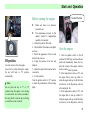
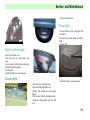
Trunk Cover
Insert the key into the keyless entry and
turn it clockwise to open the trunk cover.
Put down or push down the cover and
close and lock it.
!Notice
The exhaust gas is harmful. After opening
the trunk cover, turn off the engine to
avoid the gas coming into the cab.
You should assemble the children
protection system at the back seat. If the
system is too small for your child, just let
him sit at the back seat and t ie up the seat
belt.
24
Notices Before Drive
Trunk
cover
the left side under the driver seat.
Notice when filling the fuel:
1. Shut down the engine.
2. Pull up the fuel fill door unlock
joystick to open the fuel fill door.
3. Turn in counterclockwise to open the
fill cap.
4. Turn the cap clockwise after filling and
screw down, then close the fuel fill door.
unlock
joystick
Pull up the trunk cover unlock joystick at
the left side under the driver seat to open
the trunk cover.
!Notice
It will cause accident if you drive the car
with the trunk cover open which will
block your line of sight.So1. Do not
operate the Trunk cover unlock joystick;
2. Do not drive with the trunk cover open.
Fuel fill
joystick
door
unlock
The fuel fill door lies on the right back
board of the car.
The fuel fill door unlock joystick lies on
25
Notices Before Drive
!Notice
The fuel steam is flammable. Shut down
the engine and do not smoke or produce
fire and sparkle to avoid fire.
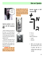
Engine Coping
2. Push upward of the claw to lift the
engine coping.
1. Pull the unlock handle at the left side
under the instrument panel to open the
engine coping lock.
Do not use plumbic gasoline to the
non-plumbic gas cars to avoid any
damage to the engine and e xhaust system.
Gasoline will damage the painting. If the
gasoline spatters on to the painting, wash
it with cold water immediately. The
gasoline in the fuel tank might be
compressed. You can screw loose the fuel
tank cap slowly. In cold weather, the fuel
fill door may not be opened easily; you
can open it by pushing or knocking it.
26
Notices Before Drive
the hole beside the engine room to brace
the coping.
4. Press the knighthead into the clamp to
avoid vibration before closing the coping.
5. Lay down the coping and let it fall
from about 30cm (1 inch) height. Close
the coping and shake the edge of it to
ensure it has been locked.
!Notice
Opening the engine coping in traveling
will cause accident which would block
the front line of sight. Pull the edge of the
coping to check whether it has been
completely closed before driving. Do not
operate the engine coping unlock handle
during driving. Do not drive with the
coping lifted. If the coping is open, the
3. Insert one end of the knighthead into
car still can be started. So before loose
the coping unlock ouch, pull off the
ignition key and set the transmission at
1-speed or back-up and pull the parking
brake. When the engine is running, open
the engine coping and the running
components bare at this time, do not wear
loose clothes or let hands and hair to
touch the running components to avoid
any unnecessary damage.
27
Notices Before Drive
28
Notices Before Drive
29
Start and Operation
Start and Operation
30
Start and Operation
31
Start and Operation
Fuel Suggestion
Use non-plumbic gasoline with high
quality for commercial purpose. The
quality of gasoline decisively affects the
dynamic, drive performance and life of
the engine. And the additive is important
to the fuel. Please use non-plumbic
gasoline with additive of high quality. If
the octane rating is too low, it will cause
engine explosion. Chery will not be
responsible for any loss caused by
misusage of the fuel. Please use fuel with
high quality.
! CAUTION:
DO NOT apply the leaded gasoline to the
vehicle powered by the unleaded gasoline,
otherwise it may damage the engine and
exhaust system, and any damage caused
herein is without warranty. To prevent the
unintended leaded gasoline refilling, the
leaded gasoline pipe can’t be inserted into
the unleaded gasoline filler port.
Operation at overseas
If you drive Chery cars in other country,
make sure to:
Obey the laws and security
regulation.
Affirm whether there is proper fuel
provided.
When using oil tank and oil storage
cont ainers
(especially
those
unprofessional filling equipments) to fill,
the storage pump and the tube must be
earthed properly for the sake of safety.
When the fuel flows under a certain
pressure, a large deal of static will
produced if the filling tube is not earthed
(especially p lastic pipe)
Be advised to use earthed filling
equipments and tube. The container
should be earthed in unprofessional
filling op eration.
B position
Pull out the key to lock the pole.
Turn the steering wheel till it locked.
To conveniently turn the key when
opening the lock, you can turn the
steering wheel counterclockwise to let the
key turning to “I” position.
I position
Can not lock the steering wheel but can
shut down the engine.
Operate normally at this position just like
op erating radio and cigarette lighter.
lI position
Ignition Switch
There are 4 positions at the ignition
switch on the right of the turning pole: B,
I, II and III.
Can start ignition system and accessories
of the app liances.
32
Start and Operation
Before starting the engine
Neutral Pos ition
III position
Can start motor to drive the engine.
Loose the key after starting the engine,
the key will back to “II” position
automatically
!Notice
Do not place the key to “I” or “II”
position when the engine is not running
to avoid electric loss of the accumulator.
Do not pull off or turn the key in driving
to avoid the car out of control.
M ake sure there is no obstacles
around the car.
The maintenance projects in this
manual should be implemented
regularly, for example:
1、Check the position of the fuel;
2、Check whether the windows and lights
are clean
3、Watch the app earance of the tire and
check the air pressure
4、Adjust the position of the seat and
headrest.
5、Adjust the angle of the inner and outer
view mirror.
6、Tie the seat belt.
Turn the ignition switch to “II” position
to check the performance of the warning
lights.
Start the engine
1. Turn the ignition switch to the III
position, DO NOT step on the accelerator
pedal, and immediately loosen the key
after the startup of the engine and then
the key returns to the II position.
2. If the temperature is above -12℃ and
the engine fails to start up within 5 s
when the engine starts up in the first time,
turn the key to the B position, and retry
after waiting for 10 s.
3. If the temperature is below -12℃ and
the engine fails to start up within 15 s
when the engine starts up in the first time,
turn the key to the B position, and retry
33
Start and Operation
after waiting for 10 s.
If the engine fails to start up in the
continuous two times, step on the
accelerator pedal to its end and keep it in
the position, turn the key to the III
pos ition, and then loosen the key after the
startup of the engine, subsequently, with
the speedup of the engine, slowly release
the accelerator pedal.
4. For the vehicle equipped with the AMT
transmission, let the engine op erate at the
idle speed for several seconds after
startup, step on the foot brake, loosen the
hand brake, shift to the driving gear, and
then drive the vehicle.
5. For the vehicle equipped with the
manual transmission, let the engine
op erate at the idle speed for several
seconds after startup, step on the clutch,
shift to the driving gear, release the hand
brake, and then drive the vehicle.
! CAUTION:
Before the gear shifting, please pull up
the hand brake or step on the foot brake,
otherwise, when shifting the gear, the
vehicle may move to cause the damage or
injury.
6. The ambient temperature condition is
-25℃-40℃ for the normal startup and
operation of the engine (when the
ambient temperature is not within this
range, it may result in the difficulty to
start up the engine. This is a normal
case).
Warming-up
In cold weather, let the engine run in idle
for 30 min. after starting and then drive a
distance with middle speed.
running can not exceed 5 min. If the
engine failed start, just step slowly down
the accelerate panel and maintain, then
start the engine.
Operation of the Manual
Transmission
Step down the clutch completely and
move the shift joystick, and loose the
clutch after shift.
!Notice
Do not shift in driving. When the car
stops completely, back-up shift can be
used to avoid any damage to the
transmission. Do not lay your foot on the
clutch panel to avoid any damage to the
clutch.
!Notice
The exhaust system will be damaged
under high temperature. So the idle
34
Start and Operation
Neutral
Pos ition
the engine still fails to start, wait for 15 s
and then have a try (for the vehicle
equipped with the automatic transmission,
turn the ignition switch, wait for 10 s and
then have a try)
Operation procedure of AMT
)
transmission (
Operation procedure to start a
engine with AMT transmission
)
(
Keep the transmission gear position on
the N gear, 1st or 2nd gear befor e the
engine starts. DO NOT step on the brake
to start the engine when the transmission
is placed in N gear position, otherwise the
engine fails to start.
Turn the key to the position “III”, and
DO NOT step on the accelerator pedal to
start the engine. After the engine starts,
release the key. If the engine fails to start,
repeat the procedure above.
! CAUTION: The starter can’t
operate for above 10 s every time,
otherwise, it may damage the starter. If
R = Reverse
N = Neutral
Manual gearshift mode
+ = Upshift
- = Downshift
1. Shift to the R position only
after the selector lever is in the
N position. And there is a
instrument alarm sound to give
a prompt;
35
Start and Operation
2. To enter the automatic gearshift
mode, press the AUTO key to
enter the mode, and press the
AUTO key again to enter the
manual gearshift mode;
3. In the case of manual gearshift
mode, push the selector lever
towards the + direction, and
then increase the trans mission
up to adjacent upper gear
position; and push the lever
towards the – direction, and
then reduce the transmission
down to the adjacent lower
gear position;
4. In the case of manual mode,
the upshift can be conducted
under any speed of the vehicle;
and the downshift can be
implemented only when the
speed drop is in allowable
range.
! CAUTION: In the case of emergency
braking, the automatic gear position
drop function can be carried out either
in the AUTO mode or in the MANUAL
mode, without the manual gear drop
operation
Start the vehicle in case of
manual transmission
After the engine starts, shift to the
proper gear position, release the brake,
and slightly step on the accelerator pedal
to make the vehicle gradually enter into
the travel state. If it is difficult to shift the
gear, slowly step on t he accelerator pedal,
and shift to the proper gear position
again.
! CAUTION: : When the vehicle
starts on a slope, the hand brake must be
pulled before the vehicle starts. Slightly
step on the accelerator pedal, release the
hand brake at the same time, and ensure
that the engine bonnet is fully closed,
otherwise, it is difficult to start the
vehicle.
Start the vehicle in case
of AMT transmission
)
(
After the engine starts, shift to the
proper gear position. Regardless of the
AUTO or M anual mode, the vehicle can
start only after manually shifting to the 1st
gear position. In case of the idle speed,
shift to the 2nd gear or below. After
shifting to the proper gear position,
release the brake, step on the accelerator
pedal and then enable the vehicle to enter
the travel state. If the accelerator pedal
isn’t stepped on, although the proper gear
position is shifted, the vehicle can’t travel
yet.
Driving Start
Put into gear after starting the engine and
loose the brake and step down the
accelerate panel slightly to start the car
gradually. If there is any difficulties in
36
Start and Operation
putting into gear, accelerate a little and
shift again.
!Notice:
If you want to start on a brae, you must
pull the parking brake and step slightly
down the accelerator panel, loosing the
parking brake at the same time. Do not
start the car with the hood open.
your drive.
If the brake pedal is lower than before,
you need to adjust the rear drum brake. If
this happens, please test your car forward
and backward and test the brake in all
directions to find out the reason.
If the pedal does not get back or the
distance is too long, please cont act with
Chery Service Station, because this
probably is a signal for the fault in brake.
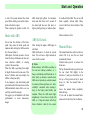
Brake
The conventional brake is designed to
satisfy the performance under all kinds of
circumstances (including fully loaded).
Your car is equipped with diagonal
crossed brake system. The front wheel is
equipped with disc brake, and the rear
wheel is equipped with drum brake.
If the first brake oil path failed, the car
can still brake with the second oil path.
When this happens, you need to step on
the brake pedal with more strength. The
brake distance will be prolonged. Please
go to the Chery Service Station to check
the brake system before continuing with
and step slightly on the brake pedal to
check whether the function has lost. Then
keep the distance with other cars for
enough space, and step slightly on the
brake pedal until it get back to work.
When crossing water (which is deep
enough to wet the components) or after a
washing, repeat the above process to
avoid any accident. The brake friction
piece and the brake cushion might be
worn, so do not lay your feet on the brake
pedal during driving.
ABS
!Notice
The brake might invalidate if it is
overheated. So 1、Use engine brake under
low gear when driving down a
declivity2 、 Do not use the brake
continuously.
If the components of the brake are hu mid,
the brake will not function for a while. So
take a look at behind for any other cars
ABS is a kind of advanced
electric brake system which can
prevent the car from sliding during
a brake.
ABS is to prevent the wheel from locking
in an emergent brake or on a smooth road,
and to keep the swerving and stability of
the car.
This system use sensor to detect the
differences amon g each wheel speed and
begin to function when the wheel is going
37
Start and Operation
to lock. The system detected the wheel
speed before locking and control relative
brake with electric signal.
When opening the ignition switch, the
Brake with ABS
Do not fear the vibration of the brake
pedal. Step down the brake pedal and
maintain until starting the ABS no matter
how the road status is.
ABS adjusts the brake pressure of each
wheel for best performance and does not
loose direction stability or steering
cont rol at the same time.
When the ABS is operating, there might
be slight vibration with some noise. This
kind of vibration and noise display the
ABS is working normally.
In an emergency, step down brake pedal
and clutch p edal at the same time, and t he
ABS immediately takes effect so as you
can fully control the steering.
We suggest you to familiarize with these
performances to avoid unnecessary
danger.
ABS alarm light glitters for automatic
check and shut down in 4-5 seconds. If
the alarm light does not shut down or
light up during driving, it indicates there
is trouble with the ABS. The car can still
brake regularly without ABS. Please
contact with Chery Service Station if this
happens.
before continue to drive.
ABS Self-check
After starting the engine, ABS begins to
self-check.
ABS self-checks is to check for system
fault. You can hear a slight mechanical
noise which is normal.
!Notice
Brake distance will differ according to
the road and running condition, so 1.
keep a safe distance with the front car. 2.
drive slowly on humid or smooth roads.
ABS can not prevent any accident caused
by careless or false operations, so 1. drive
carefully.2. decelerate when steering.3.
Step on the brake pedal forcibly and
maintain. When the ABS alarm light
enlightened, it shows there is fault with
ABS, so 1. Stop and contact with Chery
Service Station.2. check by the experts
Manual Brake
The manual brake takes effect on t he rear
wheel. Pull it up and the rear wheel
automatically locked.
M anual brake joystick is between the
front seats.
Pull up the manual brake joystick to lock
the rear wheel. Pull slightly in the
direction (1) and press the button (2) on
the top of the joystick and lay it down
along (3), then the manual brake is
released.
Loose the manual brake completely
before driving.
If you want to adjust the manual brake,
please refer to the Chery Service Station.
38
Start and Operation
1
2
3
Stopping the car
Step down the brake pedal and
strain the manual brake.
When stopping on a horizontal road,
set the joystick to neutral gear
position. When stopping on a brae
(driving down), set the gear joystick
to back up. When stopping on the
brae (driving up), set the joystick to
1 s peed position.
Close all the windows and
clearstory.
Turn the ignition key to “B”, and
pull off the key.
Lock all the doors and trunks.
Ensure the car has stopp ed
completely.
!Notice
The exhaust components are so hot that
may cause fire. Do not stop on flammable
things, such as grass or straw. The car
might move when stopping, so1. Pull up
the manual brake. 2. Choose the hard
road to stop. 3. Do not back steering
wheel to the straight direction when
stopping on the mountain.4. If you did
not loose the manual brake, it will do
harm to the rear brake. Loose the manual
brake completely before driving. The
flammable things will self-ignite if it
touches the hot exhaust components on
the bottom of the car, so do not stop or
drive the car near the flammable things.
The manual brake will be frozen if
crossing the water (which is deep enough
to make the components humid) or after
washing. If it froze, you should 1. Pull up
the manual brake, and set the gear
joystick to 1-speed or back up; 2. Lock
the rear wheel to ensure the car cannot
move; 3. Loose the manual brake.
Suggestion on
Economized operation
The economy of fuel depends on your
operation. The way you drive, the place
and the time you drive will influence the
distance that 1 L fuel can drive.
For best fuel economy:
Start smoot hly and accelerate
slowly.
Adjust the engine properly.
Do not leave the engine running in
idle.
Use air conditioner if it is really
needed (if there is the equipment).
Decelerate when driving on an
accidented road.
Keep the air pressure in the tire
with standard for the best fuel
39
Start and Operation
economy and prolong the life of the
tire.
Keep certain distance with other
cars to avoid emergency brake so as
to depress the wear and tear of the
brake patch and improve the fuel
economy(because there is no need
for additional fuel to accelerate).
Do not load unnecessary goods to
add the weight.
Do not leave your feet on the pedal
which will cause unnecessary worn
or even damage the brake and
increase the consume of fuel.
Keep the condition when the car
left the factory.
Notice the exhaust gas of the engine
(carbon monoxide)
Do not inhale the exhaust gas of the
engine which is harmful, or you
will examinate or even die with
excessive gas.
Whenever you suspect that there is
exhaust gas entering the car, go to the
Chery Service Station immediately for a
check. If you have to drive under this
condition, please open all the windows
completely.
To prevent the gas from entering the car,
please check the exhaust system and body
regularly.
Lift the car and check when
replacing the oil.
Notice the change of the sound of
exhaust system.
Do not let the exhaust system,
chassis or the tail be damaged or
corroded.
Notice at the same time:
Do not start the engine in a narrow
place such as garage or other closed
places.
When the engine maintain running
for a long time in an open
circumstance, you should set the
conditioner to outer circulate mode
and let the fresh air into the car, and
set the blower to high speed
position.
Do not stay in a car with engine
running idle for a long time, neither
leave the children in it.
Avoid the tail door open during a
driving because the exhaust gas
might get into the car. If the tail
door has to be opened, please close
all the windows. Set the conditioner
to outer circulate mode and let the
fresh air into the car, and set the
blower to high speed position.
Driving in danger:
When driving on watery, snowy, icy,
muddy, sandy or similar kind of
dangerous roads, you should follow these
40
Start and Operation
advices:
Start and Operation
Drive carefully for the brake
distance will be prolonged.
Avoid brake or steering.
Step slightly on the brake pedal
to avoid sliding of the front wheel.
Spread some rocks and stones
under the front wheel when the car
getting stuck in snow or mud, or
use tire chain or other antiskid to
increase the adh esive power.
until it stops during a brake.
If the car get stuck in snow, mud or
sand, accelerate with 2-speed gear
41
Instruments and control devices
Instruments and control devices
42
Instruments and control devices
43
Instruments and control devices
44
Instruments and control devices
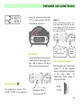
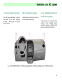
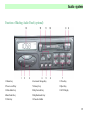
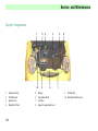
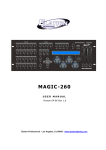
1.Steering switch
14.Rear window defroster switch
2.Horn button
15.Radio/cassette
3.Cluster gauge
16.Airflow distribution switch
4.Ignition switch
17.Ashtray
5.Wiper switch
18.Package bo x
6.Temperature cont rol switch
19.Cogarette lighter
7.Center ventilation opening
20.Interior and outer circulation control lever
8.Hazard warning switch
21.Accelerator pedal
9.Anti-theft indicator light
22.A/C switch
10.Blower motor switch
23.Brake pedal
11.Side ventilation opening
24.Clutch pedal
12.Front windshield defroster ventilation opening
25.Engine hood inner opener handle
13.Glove box
26.Headlight regulator switch
45
Instruments and control devices
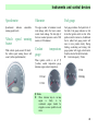
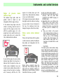
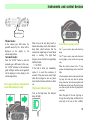
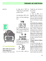
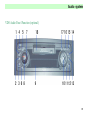
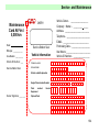
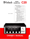
Speedometer
Speedometer
ind icates
running speed (km/h)
Vehicle
buzzer
speed
automobi le
warning
While vehicle speed exceeds 120 km/h ,
the vehicle speed warning buzzer will
sound ( within specified market)
Odometer
Fuel gauge
The upper counter of odometer records
total mileage, while the lower counter
records travel mileage. The last digit of
the lower counter represents a unit of 100
meters (or l/10 kilometer).
Fuel gauge indicates the liquid level of
fuel tank. Fuel gauge indicates no fuel
level after ignition switch is shut. After
ignition switch is turned on, if additional
fuel is added, fuel gauge pointer will
move to new position slowly. During
braking, accelerating and turning, fuel
gauge pointer will wiggle, which results
from the shock of the fuel in fuel tank.
Fuel tank capacity: 35Litre.
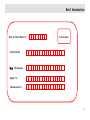
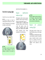
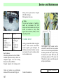
Coolant
gauge
temperature
When ignition switch is set in" Ⅱ
"position, coolant temperature gauge
indicates engine cool ant temperature.
F:Full
H: Cool
E:Empty
C: Hot
!Notice
When indicator stays in red area,
engine
is
likely
to
be
overheated ,engine should be
stopped as soon as possible to cool
down.
46
Instruments and control devices
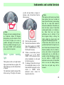
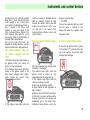
added in time if the warning light is on.
Fuel level warning light
Fuel will run out soon when the light
goes on.
The lamp will light up when the
remaining fuel in tank drops to 5.5 liters.
Once the warning light is on, fuel should
be added as soon as possible.
Engine
malfunction
indicator light
With ignition switch is turned on, engine
malfunction indicator light will light up
for about 4 seconds until it goes out.
If indicator light is on, during normal
operation, it indicates a fault. The electric
cont rol fuel injection system will
switched to emergency mode to keep
driving, driver should contact CHERY
AUTO authorized service station
immediately for trouble shooting.
!Notice
If engine malfunction indicator light stays
on, it indicates a failure. Driver should
contact CHERY AUTO authorized
service station for troubleshooting.
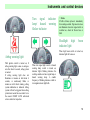
Engine
oil
warning light
pressure
With ignition switch is turned on, the
light will light up and go out after engine
is started.
If the light goes on during driving, engine
oil level should be checked. The specified
engine oil should be added to normal
level if it is because of the lack of
engine oil. If oil level is ok, cont act
CHERY AUTO authorized service
station.
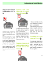
!Notice
The catalytic converter and fuel system
may function improperly if fuel is
exhausted, therefore, fuel should be
47
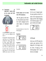
Instruments and control devices
on after the hand brake is released, it
indicates a lack of brake fluid. Take the
following steps:
!Notice
If engine oil pressure warning light stays
on, it indicates a failure. If it happens
during driving, stop the vehicle to check
for the lack of engine oil as soon as
possible. Add engine oil if necessary. If
there is no problem with engine oil, go to
the nearest CHERY AUTO authorized
service station for inspection.
Brake
light
system
warning
With ignition switch on, the light should
light up after hand brake is applied. The
light should goes out after the hand brake
is released.
The hand brake should be released fully
before moving. If the light still remains
Park the vehicle at roadside.
Check the brake fluid level; add the
brake fluid specified by CHERY
AUTO CORPORATION to the
MAX mark if necessary.
If brake is ok and brake system is
functional, go to the nearest
CHERY AUTO authorized service
station immediately at safe speed
for further inspection.
If a leakage of brake fluid is found,
the warning light remains on or the
brake functions improperly, tow the
vehicle
to
CHERY
AUTO
authorized service station for
inspection and service.
!Notice
With ignition switch turned on and hand
brake applied, there may be failure in
brake system if the brake system warning
light isn't on. Lamp bulb should be
checked for malfunction. If the bulb is ok,
check the brake system; if brake fluid
warning light remains on, it indicates a
low brake fluid level and brake
performance may be affected. If the
above happens during a driving, the
vehicle should be slowed down and
stopped for the following inspections
1.Check brake fluid reservoir and add
specified brake fluid if the liqu id level is
low.2.Check brake for function.3.If brake
functions normally, drive the vehicle to
service center slowly for inspection.4.If
warning light stays on while brake is
normal or a brake fluid leakage is found,
tow the vehicle to CHERY AUTO
authorized service station. If brake fluid
level is too low, the braking distance,
brake force and pedal range will be
increased.
48
Instruments and control devices
ABS warning light
Generator warning light
With ignition switch is turned on, ABS
indicator light will light up for about 4
seconds before it goes out.
With ignition switch turned on, if the
ABS light is not lit or remains on, contact
the nearest CHERY authorized service
station.
It indicates a discharge of vehicle battery.
With ignition switch turned on, the light
will light up and goes out after engine is
started. If the light goes on during driving,
the following steps should be taken:
·Park the vehicle at roadside.
·Check generator belt for slackness or
cracks.
·If generator belt is normal, there may be
failure in charging system. Isolate the
problem and correct it as soon as possible
and to the nearest CHERY AUTO
authorized service station for a system
inspection immediately.
If ABS light is lit up during driving, there
is a fault in ABS system With ABS not
working, if the brake system functions
properly, go to the nearest CHERY
AUTO authorized service station for
inspection.
Safety belt warning light
With ignition switch in "II" position,
safety belt warning light will come on
unless driver fastens safety belt.
!Notice
If the generator belt is too loose, the
generator sup erheating may be caused
and subsequent damage may happen to
the generator. Therefore, the generator
belt should be inspected regularly.
49
Instruments and control devices
Turn signal indicator
lamp/ hazard warning
flasher indicator
!Notice
If bulb is blown, replace it immediately
for avoiding accident. If green arrow does
not illuminate when turn signal switch is
switched on, check for blown fuse or
bulb.
Headlight high
indicator light
When high beam switch is turned on,
indicator light will come on.
Airbag warning light
With ignition switch is turned on, if
airbag warning light comes on and goes
out after about 4 seconds, airbag system
is normal.
If airbag warning light does not
illuminate or remains on after about 4
seconds, or continuously blinks or
remains on with vehicle running, airbag
system malfunction is indicated. Airbag
system will not be triggered when airbag
protection is needed in an accident. Go to
the nearest CHERY AUTO authorized
service station for inspection.
beam
When turn signal light switch or hazard
warning lamp switch is turned on,
indicator light’s blinking indicates the
working condition of outer signal lamp or
hazard warning lamp. A smaller
frequency of blinking indicates a fault in
turn signal indicator light bulb.
50
Instruments and control devices
Foglight/rear
switch
foglight
First position with front foglights on.
Second position with front and rear
foglights on or only with rear foglights
on.
With switch in second position, the
operation indicator light on switch will
illuminate.
With ignition switch on,front foglights
will op erate only when parking lights are
turned on. They may work with high
beams or low beams simultaneously. Rear
foglight can only be operative with front
foglights simultaneously.
Rear foglights are allowed to apply only
when there is a very low visibility (with a
visibility distance less than 50 meters) for
their stronger dazzle.
!Notice
Do not light up after engine is stopped, or
battery will be discharged. Headlamp
lower beam asymmetry is designed to
increase sight scope. In left driving
countries, there must be a black cover on
the headlight glass zone with 1 5 angle.
Transmission warning light
(for the vehicle with AMT
transmission)
The light ON after the ignition switch
turns on, and then off after about 4 s.
If the light fails to light after the ignition
switch turns on, or if the light doesn’t
extinguish after it lights, please cont act
the nearest special CHERY service
station. If the light ON during the vehicle
is traveling, it shows that the ABS has
fault. If there is no ABS function while
the vehicle’s brake system still works as
before, please get to the nearest special
CHERY service station ASAP to have it
examined.
51
Instruments and control devices
Transmission
oil
temperature warning light
(for the vehicle with AMT
transmission)
it examined.
Manual mode:
Position display (for the vehicle
with AMT transmission)
In the case of manual mode,
the gear position selected by a
driver will be displayed in the
display with the form of digital.
In the following figure, the 2nd
gear is taken as an example.
After the ignition switch turns
on, the position of gear selector
lever will be displayed on the
center display of instrument
panel.
All position displays are shown in the
following figures:
The light ON after the ignition switch
turns on, and then extinguishes after
about 4 s.
If the light fails to light after the ignition
switch turns on, or if the light doesn’t
extinguish after it lights, please cont act
the nearest special CHERY service
station. If the light ON during the vehicle
is traveling, it shows that the ABS has
fault. If there is no ABS function while
the vehicle’s brake system still works as
before please get to the nearest special
CHERY service station A.S.A.P. to have
R position:
AUTO mode:
N position:
In the case of AUTO mode, the
current gear position will be
displayed in the display with
the form of digital. In the
following figure, the 2nd gear is
taken as an example.
52
Instruments and control devices
traveling time switchover/reset button, and the
“ SEL” is a function select button. The profile
of this instrument is shown below:
Speedometer
The speedometer displays the running speed of
a vehicle (unit: km/h), with the range of 0–199
km/h, which is displayed in the form of
digitals, and the division of display: 1 km/h.
Digital instrument (
Odometer
With the digital display, the odometer has a
overall mileage count er (ODO) which can record
the max. mileage of 999,999 km; and two trip
meters (TRIP A/TRIP B) which can record the
max. mileage of 9,999.9 km.
Two trip meters (TRIP
A/TRIP
B)
and
travelling time display
Overall
mileage
display
Water temperature indicator
When the ignition switch is placed on the
position “Ⅱ”
, the water temperature
indicator will indi cate the temperature
of
the
engine
coolant.
The
column-shaped display includes 10
scales and 10 divisions.
)
This instrument has two keystrokes: “ SEL”
and “T RIP”; the “TRIP” is a trip computer and
Speedometer Display
H: Hot
C: Cold
53
Instruments and control devices
Fuel alarm indicator lamp
! CAUTION:
When the pointer gets to the red area, the
engine may he overheat, and you shall
immediately stop your vehicle to cool the
engine. In this case, if you drive your
vehicle continuously, it may damage the
engine.
In case that this indicator lamp lights, it
indicates that the fuel will be used up
soon. When the fuel remained in the tank
reduces down to 5.5 L, this indicator
lamp lights. Refuel as soon as possible
once the alarm indi cator lamp lights.
Authorized Service Station to remove the
trouble.
Fuel gauge
The fuel gauge indicates the level of fuel
remained in the fuel tank. The gauge
will not display the fuel level after the
ignition switch closed. If refuelling into
the tank, the reading of fuel gauge will
slowly change to the new level of fuel.
In case of braking, accelerating or
turning, the pointer of fuel gauge will
waggle. This is caused by the vibration
of fuel in the tank.
● Capacity of fuel tank: 35L.
F: Full
E: Empty
Engine trouble indicator lamp
The engine trouble indicator lamp lights
when the ignition switch is turned on, and
extinguishes after the engine starts up.
If the indicator lamp lights when the
engine operates normally, it shows that
there is a certain trouble. In this case,
switch the electronic injection system to
the emergency running program, and then
drive the vehicle continuously, however,
immediately
cont act
the
Chery
If the engine trouble indicator lamp lights
in a short time and then extinguishes, it is
a normal phenomenon and doesn’t show
that the system has any trouble..
!CAUTION
In case that the engine trouble indicator
lamp lights for a lon g time, it indicates
that the engine has some one trouble, and
you shall contact the Chery Authorized
Service Station and remove the trouble in
time.
54
Instruments and control devices
Engine oil pressure
indicator lamp
alarm
The indicator lamp lights when the
ignition switch is turned on, and
extinguishes after the engine starts up.
If the indicator lamp lights when the
vehicle is traveling, check the level of
engine oil. If the engine is short of oil,
refill the specified engine oil to the
normal level of oil; and if the oil level is
normal, please take care to cont act the
Chery Authorized Service Station.
!CAUTION
In case that the engine oil pressure alarm
indicator lamp lights for a long time, it
indicates that the engine has some one
trouble, please immediately stop your
vehicle to check whether there is short of
engine oil when the vehicle is traveling,
and, if necessary, refill the oil; if the
engine oil is normal, please get to the
nearest Chery Authorized Service Station
to have your vehicle checked.
If the engine oil pressure alarm indicator
lamp lights when the vehicle is traveling,
stop your vehicle to have it checked. In
this case, the continuous travel may
damage the engine, without the warranty.
Brake system alarm indicator
lamp
Pull up the hand brake after the ignition
switch is turned on, and then the indicator
lamp lights, and extinguishes after the
hand brake is released.
Before driving, completely release the
hand brake. If the indicator lamp still
lights after the completely releasing of
hand brake, it shows that there is short of
brake fluid. In this case, you shall:
● park your vehicle on the roadside;
● check the level of brake fluid, and, if
necessary, refill the brake fluid
specified by the CHERY company to
the M AX mark;
● immediately drive your vehicle at the
safety speed to the nearest Chery
Authorized Service Station to have it
checked if the brakes are normal and
the brake system is confirmed very
safe;
● drag your vehicle to the nearest
Chery Authorized Service Station to
have it checked and repaired if you
find any one of the following
troubles: brake fluid leakage, the
alarm indicator lamp lights for a
long time, or the brake fails to work
normally.
!CAUTION
The brake system alarm indicator lamp
doesn’t light after the ignition switch is
turned on and the hand brake is pulled up,
it shows that the brake system may be in
trouble. Check whether the bulb has some
troubles. If the bulb is working normal,
check the brake system; if the brake fluid
alarm indicator lamp lights for a long
time, it indicates that the level of brake
fluid is low, which may make influence
on the braking performance. In this case,
if you are driving your vehicle, you shall
gradu ally decelerate till stop your vehicle,
and carry out the following checks:
1. check the brake fluid reservoir, and if
55
Instruments and control devices
the fluid level is low, refill the specified
brake fluid. 2. check whether the brake
works normally or not. 3. slowly drive
your vehicle to the M aintenance Center to
have it checked if the brakes work
normally. 4. drag your vehicle to the
Chery Authorized Service Station if the
alarm indicator lamp lights for a long
time and any brake works abnormally or
the brake fluid is found leakage.
The too low brake fluid level may
lengthen the braking distance, and also
increase the brake force and p edal travel.
vehicle is traveling, it illustrates that the
ABS has trouble(s). Without the ABS
function, the vehicle’s brake system still
works as usual. However, in this case,
you shall get to the nearest Chery
Authorized Service Station to have your
vehicle checked.
charging system checked.
!CAUTION
The too loose generator belt may result
that the engine is overheat. It may
damage the engine. So, regularly check
the generator belt.
Generator alarm indicator lamp
Seat belt alarm indicator lamp
In case that the ignition switch is placed
to the position “Ⅱ”
, unless the driver has
put on the seat belt, the seat belt alarm
indicator lamp will light.
ABS alarm indicator lamp (for
the models equipped with the
ABS)
The indicator lamp lights after turning on
the ignition switch, and, waiting for
approx. 4 s, then extinguishes.
If the indicator lamp doesn’t light after
turning on the ignition switch, or the
lamp doesn’t extinguish after it lights,
please cont act the nearest Chery
Authorized Service Station.
If this indicator lamp lights when the
This alarm ind icator lamp indicates that
the battery is discharging.
The indicator lamp lights when the
ignition switch is turned on, and
extinguishes after the engine starts up.
If the indicator lamp lights when the
vehicle is traveling, you shall
● park your vehicle on the roadside;
● check whether the belt of generator is
slack or broken
● find out the trouble ASAP and remove
it if the belt is in good condition and the
charging system may be in trouble, and
immediately get to the nearest Chery
Authorized Service Station to have the
56
Instruments and control devices
Airbag alarm indicator lamp (for
the models equipped with the air
bag)
The indicator lamp lights after turning on the
ignition switch, and, waiting for approx. 4 s, then
extinguishes. It illustrates that the airbag system is
normal.
If the indicator lamp doesn’t light or the lamp
doesn’t extinguish after it lights for 4 s, or blinks
continuously and even lights for a long time when
the vehicle is traveling, it indicates that the airbag
system has trouble(s). In the case of troubl e, the
airbag system fails to be activated, please
immediately cont act the nearest Chery Authorized
Service Station to have it checked. If the airbag
system can’t be repaired in time, it can’t play its
proper role after the serious compact occurs. Any
damage or injure caused herein is exclusive in the
warranty.
Transmission
trouble
alarm
indicator lamp (for the models
with the AMT transmission )
The indicator lamp lights after turning on
the ignition switch, and, waiting for
approx. 4 s, then extinguishes.
If the indicator lamp doesn’t light after
turning on the ignition switch, or the
lamp doesn’t extinguish after it lights,
please cont act the nearest Chery
Authorized Service Station.
Transmission
trouble alarm
the models
transmission
oil temperature &
indicator lamp (for
with the AMT
)
The indicator lamp lights after turning
on the ignition switch, and, waiting for
approx. 4 s, then extinguishes.
If the indicator lamp doesn’t light after
turning on the ignition switch, or the
lamp doesn’t extinguish after it lights,
please cont act the nearest Chery
Authorized Service Station.
Gearshift display (for the models
with the AMT transmission )
The position of gear selection lever will
be displayed on the display located at the
center of the instrument panel after
turning on the ignition switch. It will
display the position of each gearshift in
the column-shaped form.
57
Instruments and control devices
Gearshi ft display
Manual mode:
In the manual gear shift mode, the
gearshift selected by the driver will be
displayed on the display in the
column-shaped form.
Automatic mode:
Press the “AUTO” button to enter the
automatic gear shift mode. In this case,
the “AUTO” indicator in the instrument
panel will light, and the current gearshift
will be displayed on the display in the
column-shaped form.
Turn signal indicator lamp/hazard
alarm flash indicator lamp
When turn on the turn lamp switch or
hazard alarm lamp switch, their indicator
lamp flash, which ind icates that the
external turn signal lamp or hazard alarm
lamp is working. The high flash
frequency shows that the turn signal lamp
bulb has trouble.
!CAUTION
If the bulb is burnt out, immediately
replace it to avoid the occurrence of
accident. If the green arrow doesn’t light
when the turn signal is sent out, please
check whether the fuse and bulb are burnt
out.
High beam indicator lamp
Turn on the high beam, this indicator
lamp will light.
Front/Rear fog lamp switch
The 1st gear is used to turn on the front fog
lamp.
The 2nd gear is used to turn on the front and
rear fog lamps, or turn on the rear fog lamp
only.
When the switch is placed to the 2nd gear
position, the indicator lamp on the switch will
light.
After the ignition switch is turned on, the front
fog lamp will work only after the position
lamp is turned on, and can work together with
the high beam or low beam. The rear fog lamp
can work only with the front fog lamp at the
same time.
Since the glare of the rear fog lamp is
strong, the rear fog lamp is allowed to be
used only in the case of low visibility
58
Instruments and control devices
(below 50 m).
the display mode of “TRIP” and
“Traveling Time”. Its specific op eration
procedure is as follows:
1. The initial display is TRIP A. If the
TRIP A is 1,357.9 km, the TRIP display
shows:
2. Press the “TRIP” button once, the
TRIP A is switched to the TRIP B. In this
case, if the TRIP B is 2,468.0 km, the
TRIP display shows:
3. Press the “TRIP” button again, the
TRIP B changes to the Traveling Time. In
this case, if the traveling time is: 1h 35m,
it will be displayed as:
How to operate these instruments
●TRIP A, TRIP B and Traveling Time
switchover, display and reset
The function of “TRIP” button is to select
4. In case of TRIP A, TRIP B or
Traveling Time, press the button for
above 2 s to reset.
——Description:
(1) These two TRIPs can be
independently applied. For instance, the
TRIP A can be used to record the total
mileage each a tank of fuel, and the TRIP
B to record the mileage each out going
travel.
(2) The Traveling Time is designated to
display the time counted from the startup
of engine. For example, in accordance
with the operation procedure above, the
display is turned to “Traveling Time”
mode during the vehicle is driving. In this
case, if the time is displayed as 3-25, it
illustrates that the vehicle has traveled
continuously for 3 hours and 25 minutes.
Apart from the manual reset, this timer
also begins to count from 0-00 when the
engine restarts.
● Temporary adjustment of brightness
of the display
In case that the instrument lights, press
the “SEL” key to adjust the brightness of
the display. The brightness adjustment is
divided into 10 levels each a cycle. The
brightness level increments if you press
the key once. When the brightness
reaches its maximum value, press the key
59
Instruments and control devices
once, and then the brightness level will
return back to the minimum value.
● Clock’s integral point calibration
In case that the clock displayed is within
the integral point to or past 2 minutes,
press the “TRIP” and “SEL” buttons at
the same time to calibrate the integral
point of the clock. For instance: When the
time displayed is 14:59 but the actual
time is just 15: 00, this calibration
op eration can immediately calibr ate the
clock to 15:00.
● Setting
The following functions can be
implemented only after entering the
setting status.
● Enter the setting status
Press the key “SEL” for 2 s to enter the
setting status. In this case, the “SET”
mark on the odometer flashes, which
indicates that the instrument has entered
into the setting status.
● Exit from the setting status
In case of setting status, if press the key
“SEL” for 2 s or 15 s and do not carry out
any other operation, the instrument exits
from the setting status and the mark
“SET” extinguishes.
1. Clock initialization
In case that the mark “SET” flashes,
simultaneously press the “SEL” and
“TRIP” buttons once for a short time to
enter the clock initialization mode. In this
case, the Hour digital flashes. Press the
“TRIP” button to adjust the value of Hour
digital, with the increment every a press.
If press the “TRIP” button and keep it,
the Hour digital increases automatically
till the Hour digital is right; if it is
unnecessary to adjust the Hour value,
directly press the “SEL” button to enter
the M inute adjustment status. In this case,
the Min digital flashes. Press the “TRIP”
button to adjust the value of M in digital,
with the increment every a press. If press
the “TRIP” button and keep it, the M in
digital increases automatically till the
M in digital is right.
After the completion of adjustment,
simultaneously press the “SEL” and
“TRIP” buttons for a short time to
complete the clock setting.
1. Daytime display brightness setting
Press the “SEL” button to enter the
setting status. The SET code is displayed
as follows:
It means that in the case of “Daytime
Display Brightness” setting status, the left
two digitals represent the daytime
brightness setting status mark while the
right three digitals represent the set value
which can be selected from 1 to 100 and
the initial value is max. 100. Press the
“TRIP” button once to decrease the value
by 10. For instance: To adjust the
brightness to 85, its operation procedure
is as follows: Press the “TRIP” button t ill
the value displayed is 90, and then release
the button and press the “TRIP” button
five times to get the brightness of 85.
2. Nighttime display brightness
adjustment
Press the “SEL” button to enter the
setting status. The SET code is displayed
as follows:
60
Instruments and control devices
It means that in the case of “Nighttime
Display Brightness” setting status, the left
two digitals represent the nighttime
brightness setting status mark while the
right three digitals represent the set value
which can be selected from 1 to 100 and
the initial value is min. 001. Press the
“TRIP” button once to increase the value
by 1, and press the “TRIP” button and
keep it, the value will automatically
increase by 10. For instance: To adjust
the brightness to 35, its operation
procedure is as follows: Press the “TRIP”
button till the value displayed is 30, and
then release the button and press the
“TRIP” button five times to get the
brightness of 35.
3. Nighttime display brightness control
priority setting
Select any one of the following cases: the
brightness adjustment knob has priority
over the setting or vice versa. The initial
default is that the brightness adjustment
knob control has the priority.
Press the “SEL” button to enter the
“Nighttime Display Brightness Control
Priority” setting. And it is displayed as:
In this case, it presents the brightness
adjustment knob control priority status.
Press the “TRIP” button once. And it is
displayed as:
In this case, it presents the instrument
internal setting priority status.
4. Service mileage setting
Press the “SEL” button to enter the
“Service M ileage” setting. It is displayed
as:
is not set yet. Press the “TRIP” button
once to increase the value by 100, and
press the “TRIP” button and keep it, the
mileage value will automatically increase
by 1,000. For example: To set the service
mileage to 7,500 km, its operation
procedure is as follows: Press the “TRIP”
button till the value displayed is 7,000
and then release the button, and press the
“TRIP” button five times to get the
service mileage of 7,500 km.
When the vehicle travels 7,400 km, 7,450
km and 7, 500 km respectively, the
odometer will display respectively as
follows:
The left one digital presents that the
instrument is in the Service M ileage
setting status while the right four digitals
present the set value of mileage which
can be selected from 100 to 9,900 km. Its
initial value is 0000 which means that it
61
Instruments and control devices
It shows that the mileages remained from
the service mileage set are 100 km, 50
km and 0 km respectively. Each reminder
is accompanied by the beep sound, with
the duration of 10 s.
● Status or initial value of the
instruments re-powered after power off
Both the positive input of power supply
and the positive input of ignition switch
POWER OFF, and the relevant data of
the instruments will be lost after
re-powered on. The related initial values
of common instruments can be restored
as follows:
⒈ Clock display: 00:00
Headlight
high
beam
switch
With headlight low beam on, headlight
high beam will be turned on when control
⒉ Traveling time: 00-00
⒊ Service mileage: 0, it is required to
reset.
⒋ Brightness value: Daytime----100;
Nighttime----1.
⒌ Brightness control mode: The default
mode is knob-operated control.
moved down. Turn signal lights will go
out after turn and turn switch returns to
normal position.
When driveway shift is made ,move
switch not completely (without finishing
full travel) and hold on it. Turn signal
light switch will return to its normal
position after released.
Turn signal light switch
Turn signal lights may work only when
ignition switch is turned on. A right turn
will be signaled when turn signal light
switch is moved up. A left turn will be
signaled when turn signal light switch is
lever is pushed towards dashboard and
high beam indicator light will light up
simultaneously.
Headlight low beam will be lit up when
control lever is pushed back to original
position.
!Notice
Here, headlight
switch
must
"
" position all the time.
stay
62
Instruments and control devices
Passing light switch
HIGH= continuous wiping, high speed
Fuzzy function
Headlight high beam will come on if
control lever is turned towards steering
wheel, then cont rol lever may be released.
Control lever will return to normal
position after released. Headlight high
beam will remain on when control lever
is hold on by driver.
Windshield wiper switch
With ignition switch turned on,
windshield wiper may be operated when
control lever is turned upward.
OFF=stop.
INT=intermittent wiping (with a interval
of 4 seconds)
LOW= continuous wiping, low speed
If driver turn control lever to INT
position lightly and release it, wiper will
op erate once. Wiper will work once after
control lever return to normal position
automatically.
!Notice
If wiper blades are worn, which will
cause a improper wiping affecting front
sight, wiper blades should be replaced.
With no water, wiper's operation will
scrape glass resulting in premature
deterioration of wiper blades and
disturbing driver’s visual field. Wiper is
not suggested to apply when water is not
available.
Windshield
washer
switch
With ignition switch on, liquid in washer
will be injected to windshield if control
lever is turned towards steering wheel. If
control lever is turned less than 0.5
second, liqu id in washer will be injected
to windshield at first, then windshield
wiper will op erate several cycles. Wiper
will stop automatically after cont rol lever
is released.
63
Instruments and control devices
3/4 of its capacity. Turning control lever
in the reverse direction of steering wheel
may operate luggage compartment cover
wiper and washer.
!Notice
For windshield should not be wiped when
there is no water in washer tank, so front
sight will be affected. Therefore, 1.Stop
vehicle to add washing liquid if it is
necessary to clean windshield during
running.2.Check washing liquid level
before a travel. In cold weather,
windshield may freeze, which will disturb
driver's sight. Windshield should be
heated before it is applied. Do not apply
wiper if there is no water in washer tank.
Do not apply washer more than
overheating may damage 10 seconds in
case washer motor. In cold weather,
washing liquid may expand, which may
damage washing fluid tank and result in a
washer failure. Hence, it is sufficient to
fill washing tank with washing fluid to
!Notice
With no water, rear window wiper's
operation may scrape glass, which will
result in a premature deterioration of
wiper blades and disturb driver's front
visual field. Therefore, do not apply rear
window wiper when there is no water
available.
Adjustment Switch
Headinglight Beam
First position (Rest position)=Wiper
operative
Second
position
(Arm
turning
position)=Wiper and washer operative
simultaneously When control lever is
moved to first position, wiper will work;
when control lever is moved to second
position, washing liquid will be injected
to rear window.
of
Turn on headlight low beam and adjust
headlight beam scop e for making a clear
view of front road.
0=Off
1=Front and rear foglight power switch
2=Headlight switch
Night light control switch is design to
regulate the intensity of instrument
cluster lighting.
64
Instruments and control devices
driveway when a emergent parking or
traffic handicapping is avoidless.
Hazard warning flashlight
switch
When hazard warning flashlight switch
on dashboard is pressed, hazard-warning
flashlight will be turned on and all turn
signal light will light up simultaneously.
After once more a press, all lights go out
at the same time. Hazard warning
flashlight may be operated no matter
whether ignition switch is turned on.
Apply hazard warning flashlight to warn
other drivers and try to avoid stopping on
Rear window
switch
defroster
With ignition switch in"Ⅱ"position, rear
window may be defogged or defrosted by
pressing rear window defroster switch.
When rear windshield defroster is
op erative, the indicator light on rear
window defroster switch will come on.
Rear windshield defroster may be turned
off by pressing switch once more.
!Notice
For rear windshield defrosting heating
element is attached to the inner surface of
rear windshield, defrosting function will
be out of work if heating element is
damaged. Hereby, sharp tools or cleaning
solution with corrosive ingredient
contained is not allowed to used for
cleaning the inner surface of rear window.
Defroster will consume a great deal of
power, which may cause battery
discharging. Hereby, defroster is not
suggested to apply before engine is
started. Rear windshield defroster should
be shut once cleaning is finished. In snow
weather, the snow on rear windshield
should be cleaned first, then rear window
defroster switch may be turned on.
65
Instruments and control devices
Digital clock
After ignition switch is turned on, digital
clock will indicate time. There is a button
on digital clock which is designed to
adjust time when necessary: Press button
and hold on for 4 seconds, the hour
number on clock will blink frequently.
Accordingly, every button press will
increase an hour of the time on digital
clock. After hour time adjustment is
finished, wait for 5 seconds and the
minut e number on digital clock will blink
automatically, Accordingly, every button
press will increase one minute of the time
display on digital clock. When time
display does not blink after time
adjustment is finished and wait for
several seconds , all time adjustment is
finished.
!Notice
Clock should be readjusted if battery is
ever disconnected or fuse is replaced.
Cigarette lighter
Front ashtray
With ignition switch in "I” or"Ⅱ"position,
cigarette lighter will work once button
is pressed.
Cigarette lighter will be ejected
automatically when it gets hot .
!Notice
Cigarette lighter heating pipe will get hot
during functioning, which may cause a
burning. Do not touch cigarette lighter
heating pipe. children are forbidden to
toy with cigarette lighter .Do not press
cigarette lighter when it gets extremely
hot. Do not mistake cigarette lighter
socket as a receptacle, which may cause
damage or electrical failur e.
Pulling it backwards may open front
ashtray. Push it back in p lace after usage.
If ashtray needs to be emptied, op en
ashtray completely and depress metal
boat, then pull out ashtray.
66
Instruments and control devices
Horn button
Cup holder
Horn will blow if steering wheel (without
airbag) center or the left/right side of
steering wheel (with driver's airbag) is
pressed. Horn may blow whatever
position ignition switch is. Try to avoid
using horn.
Cup holder is located on front console
and designed to hold cup.
!Notice
With vehicle running, the liquid in cup
may spill out . So do not use cup holder
while driving.
"on" position:Interior light will remain on
despite door is open or not.
“DOOR
Position”:(Between
"ON"
position and "OFF" position "):Interior
light will illuminate when vehicle door is
op ened.
“OFF' Position:Interior light will not
illuminate even if door is open.
Glove box
Interior light
There is three positions for interior light.
Glove box may be opened by
pulling its handle.Glove bow can
be closed by pushing glove case
smoothly.
67
Instruments and control devices
!Notice
If accident or emergent braking happens
during running with glove box cover
open, personal injury may be caused,
therefore, glove box cover should be shut
during driving.
Makeup mirror
M akeup mirror is located in the back of
right sun visor.
!Notice
Driver's vision may be disturbed if
something is hung on accessory handle,
therefore, do not hang anything on
accessory handle.
Sun visor
Sun visor may be rotate up and down,
also sideways to protect driver and
passengers from highlighting.
Accessory handle
Accessory handle is located on the upper
part of front passenger door and designed
to supply convenience for passengers.
68
Ventilation and A/C system
Ventilation and A/C system
69
Ventilation and A/C system
70
Ventilation and A/C system
Control panel
Ventilation and heating
1.Temperature control switch
2.Airflow distribution switch
3.Blower motor switch
4.Internal and external circulation control
lever
5.A/C switch
A/C system regulates temperature by cold
and hot air and temperature could remain
constant at any speed. Blower decides
airflow speed. Blower may be turned on
during running if necessary.
71
Ventilation and A/C system
Center ventilation opening
Side ventilation opening
Air, after being conditioned, is directed
into vehicle by two center ventilation
openings.
Setting grids can change
airflow direction
Conditioned air is directed into vehicle by
two side ventilation openings.
Front windshield defroster
ventilation opening
Cold and warm air is directed to Side
window by front windshield defroster
ventilation openings (controlled within
the scope of outer back view mirror)
1、Front windshield defroster ventilation opening2、Side ventilation opening3、Center ventilation opening
72
Ventilation and A/C system
Temperature
switch
control
Temperature control switch is used to
control the air temperature of ventilation
opening.
Blue position: Cold
Red position: Hot
Blower motor switch
Blower motor switch is used to control
blower motor speed (four positions in all).
Blower regulates wind speed. Blower
may be turned on to improve comfort
during driving.
Internal and
external
circulation control lever
It is used to select exterior fresh air or
interior circulating air.
Outer circulation mode (
)
Allow outer air get into vehicle.
Used for normal ventilation, heating and
cooling.
Internal circulation mode (
)
It is used when a internal circulation is
needed for the air in vehicle. This mode
is used to prevent outside waste gas from
getting into vehicle especially in dusty
environment, it is also applied when fast
cooling or heating of interior air is
requested.
!Notice
Continuous application of internal
circulation mode will cause interior
mugginess and fog on glass, So internal
circulation mode could not be engaged
for a little while.
73
Ventilation and A/C system
Airflow
switch
distribution
Airflow distribution switch is used to
select airflow direction. There are five
positions for switch:
" head and foot" position(
)
Air flows out from center ventilation
opening and front bottom exhaust
opening.
Head
Head and foot
Foot
Foot/defrost
Defrost
" head" position(
)
Air flows out from center ventilation
opening and side ventilation opening.
" foot / defrost" position(
)
Air flows out from front bottom exhaust
opening,
windshield
defrosting
ventilation opening and front windshield
defrosting ventilation opening.
" foot" position (
)
Air mostly flows from front bottom
exhaust opening.
" defrost" position(
)
Air flows out from windshield defrosting
ventilation openings and front windshield
defrosting ventilation openings.
74
Ventilation and A/C system
Temperature control switch: turn anti
clockwise fully
(Blue)
Blower motor switch: Full speed
A/C system
Ventilation, heating and cool ing system
parts compose a control system which
could (in any cold condition ant at any
outdoors temperature) supp ly maximal
comfort .A/C system cooling element
cools down air and removes moisture and
dust such as pollen.
A/C switch
It is used to turn on or off A/C.
After engine is started, turn blower
switch to desirable speed and engage A/
C switch to activate A/C. When A/C is
turned on, indicator light will come on.
A/C could be shut if A/C switch button is
pressed once more. When blower switch
is set in " OFF " (turned off) position,
A/C compressor will not be engaged.
Not ice
When vehicle is riding on a long slope or
in heavy traffic, A/C application will
cause engine overheating. M onitor water
temperature gauge and shut off A/C if
engine is overheated.
Maximum cooling
In torrid weather, vehicle window should
be opened for a little while to let out
indoor hot air quickly if vehicle is
exposed to sunlight for a long time.
A/C switch: On
Internal and outer circulation control
lever:(
Normal cooling
Cooling for long distance travel and
express travel.
A/C switch: On
Internal
and
external
circulation
switch:(
)
Airflow distribution switch: (
) Or
(
)
Temperature cont rol switch: Blue
Blower motor switch: Random
)
Airflow distribution switch:(
)
75
Ventilation and A/C system
Internal and external circulation control
lever:(
Head and foot
It is design for transition stage such as at
outer low temperature with no sunlight.
When temperature control switch is set
between cool (blue) and hot (red), hot air
is directed to lower space of vehicle and
cool air and natural air is directed to
upper room.
A/C switch: On or off
Internal and external circulation control
Ventilation
lever: (
)or(
)
(
Temperature control switch: Blue
Blower motor switch: Random
)
Airflow distribution switch:(
)
Temperature cont rol switch: Between
blue (cool) and red (hot)
Blower motor switch: Random
)
Airflow distribution switch:(
Temperature cont rol switch: Turn
clockwise fully
Blower motor switch: full speed
Conditioned air from outside is directed
into vehicle by center ventilation opening
and side ventilation openings.
A/C switch: Off
Internal and external circulation control
lever:(
Airflow
)
distribution
)
switch:
Notice
Do not apply compulsive heating for a
long term in case air in vehicle will get
foul and fog comes on window. Turn off
internal circulation switch if there is fog
on window or moisture in vehicle.
"compulsive heating "is designed only
for quick warming up ,then return to
"normal heating".
Compulsive heating
A/C switch: Off
76
Ventilation and A/C system
Normal heating
A/C switch: Off
Internal and outer circulation control
Temperature control switch: Red
Blower motor switch: Random
)
lever:(
Airflow
distribution
)or(
)
switch:(
Temperature control switch: Red
Blower motor switch: Random
Notice
Defrost
do not set A/C in (
)or(
)position
during
cooling.,
For
temperature
difference between outer air and
windshield may be caused and fog, which
will disturb sight, may form on the inner
surface of windshield.
A/C application may increase defrosting
efficiency. If weather is extremely moist,
A/C switch: Off or on
Internal and outer circulation control
lever:(
)
Airflow
or(
distribution
switch:(
)
Clues to the Operation of
Cooling System
If vehicle is in direct sunlight, open
window before A/C is started. Window
should be cleaned in rainy day, while
engaging A/C could lower indoor
temperature, which is effective in both
rainy day and hot weather.
When driving in region with heavy traffic,
cooling system may
be cooled
insufficiently for frequent parking and
crawling. If A/C system is off for one or
more than a month, even in winter,
engine must be idled for several minutes
with A/C on at least once each month to
keep compressor lubricated and sealed
properly prolonging system service life.
A/C compressor does not work if blower
switch is turned off.
)
77
Ventilation and A/C system
78
Audio system
Audio system
Note: If vehicle is equipped with system other than the following audio system , read carefully vehicle audio system instruction manual.
79
Audio system
80
Audio system
Function of Baoling Audio Panel (optional)
1.Volume key
6.Automatic Storage Key
11.Tune Key
2.Power on /off key
7.M emory Key
12.Eject Key
3.M ode Select Key
8.Skip Forward Key
13.LCD Display
4.Band Select Key
9.Skip Backwards Key
5.Clock Key
10.Cassette Holder
81
Audio system
Introduction to General
Buttons Function
1.Power Supply On/Off Key(POWR)
One press on (2) key turns power on;
once more press on (2) key turns off
power (Note: when power is engaged for
the first time, Radio/Cassette Player will
be in initial Operating M ode due to the
Power On Reset of main control chip).
2.M ode Select Key (M ODE)
If (3) key is pressed repeatedly,
functional mode selection will be
performed in the following order. VOL
(Volume)-BAS
(Bass)-TRE
(Tremble)-BL (R.A.L.)-FA (F.A.R)-VOL
(Volume)
In any mode, pressing on “+” or "-'”key
will regulate corresponding function level.
Volume M ode (VOL)
Pressing on “+ “ or “-“ key will regulate
corresponding volume level can b e freely
regulated within the range from 0 to 63.
Bass M ode (BAS)-
Pressing on “+” or "-" key may regulate
the content for bass and bass level can be
freely regulated within the range
between - 7 and 7.
Tremble M ode (TRE)
Pressing key “+” or “-" key may regulate
the content of tremble and tremble level
can be freely regulated within the range
between - 7 ~ 7.
Balanced M ode (BA)
Pressing key"+" or "-" key may regulate
R.A.L. sound channel volume and
volume level can be freely regulated
within the range between 15L and 15R.
3. Band Selection Key (BD)
Pressing key (4) repeatedly will cycle
radio bands in the following order:
FM l→FM 2→FM3→FM 4→AN→AM2
After band selection is finished, repress
key "
"or"
" to manually or
automatically select radio station. After
radio station is selected, press key (3) and
key "+"or"-" to regulate volume level.
4.Clock Key (CLK)
Pressing key (5) could switch over
between the display of radio frequency
and clock: If "CLK" key is pressed when
radio is in work, clock will return to
Frequency Display M ode after clock
display for 5 seconds; Pressing this key
and key " "or" " simultaneously may
adjust hour and minute.
5. Automatic P reset M emory Key (AS)
If key (6) is pressed for less than 2
seconds, pre-selected stored radio stations
in M emory Keys (1~ 6) will be displayed
in turn; Pressing the key for more than 2
seconds , character " ATP " will appear on
display, meanwhile, radio player enter
into Automatic Scanning M ode and 6
stations will be stored. Then radio will
enter into Cycling Play M ode until any of
keys (1~ 6) is pressed to select one
station.
6.M emory Key (1~ 6)
M emory Key (1~ 6) may be used to store
30 stations (18 FM , 12 AM ). If station
needs to be selected manually, you may
press the key" "or " "to key, then
press anyone of the key (1~ 6), you will
store the selected stations into the
location of program which the key is
pressed for.
82
Audio system
7.tuning Key( " "、" ")
Press the key " " or "
"
transitorily, stations may be scanned
manually step by step ( AM :9KHZ 、
FM :50HZ) until desirable stations are
found. Press the key " " or " " more
than 1 second; automatic scanning will be
enabled until desirable stations are found.
If the key " " or " "is pressed during
automatic scanning, audio frequency will
return to previous frequency.
Radio receiving operation
1.Turn on the radio, press power key (2).
When characters app ear on display, radio
is in the state of receiving signal.
2.Press band key (4), select band FM l、
FM 2、FM 3、AM l、AM 2.
3.tuning key (11) press key" " or " "
to scan stations forward or backward
manually. Press key more than 1 second;
you may start automatic scanning until
desirable stations are found.
4.Store stations
manually.
Select
desirable station, and select M emory Key
(1 ~ 6), then press the key for 2 second,
the selected station will be stored in the
key, six keys may memorize any
stations of FM l, FM2, FM 3, AMI and
AM 2.
5.Sound effect regulation. Press key "
MODE " to display character " VOL " on
screen, pressing the key " + " or " - "
within 5 seconds may change volume. If
the key" + " or " - “ is pressed in 5
seconds, display will return to main
display state. The control mode of
BASTRE 、 BL 、 FA are the same as
volume .
6.Automatic scanning storage (6). Press
key for 2 second and a signal will be
received for confirming memory function
and display scanning. Six stations with
strong signal will be stored. Press key or
anyone of the keys 1 ~ 6 transitorily, the
function will be ceased, if you cannot
find desirable six stations, these stations
will disappear.
7.Stereo. When stereo station is received,
ST9 (indicating stereo) will be displayed
automatically.
8.Scan memory stations. Press preset key
1~ 6,you will find stored stations.
Play
Play Operation
1.The procedure for start-up is the same
as receiving.
2.Insert the tape with its opening facing
right, and push it into cassette holder,
when the marks (TAPE and “
” or
“
”) indicating play and direction
display on screen, radio is in normal play
state.
3.Volume regulation is the same as radio.
4. Selecting songs. Press Fast Forward
Key (8) or Fast Backward key (9) you
may select desirable program quickly.
5.Reverse Playing Direction.
Pressing Fast Forward Key and Fast
Backward on the same time may have
83
Audio system
tape play reversely.
6.Switch between receiving and p laying
1. Push tape into cassette holder and
receiving mode will change to playing
mode.
2. Press Eject Key (12) and tape will be
ejected; playing mod e will be switched
over to receiving mode. Press Fast
Forward or Fast Backward Key ( after
fast forward、Fast Backward is finished,
radio will return to playing mode from
receiving mode).
!notice:
In any case, no broken wire is allowed to
be bare without insulation. A proper
adapter may be used to connect circuit if
necessary, or circuit overload, short
circuit, even fire, may be caused.
furthermore, main parts may also be
damaged. According to customers'
different requirements, audio system
configurations are not same. Our
corporation provides common/electronic
tuning radio; Single disk/multi-disk CD
player; Antennas with or without
amplifier etc; therefore, it is suggested to
install or refit aud io system by CHERY
AUTO authorized service station. If other
type of radio and CD player is adopted, it
must meet typ e and technology
requirements which is specified in
CHERY AUTO accessory catalogue and
ensure its correct installation. According
to CHRRY AUTO accessory catalogue
and vehicle type, customer may also
adopt other type of speaker、connector、
antennae and anti-interference unit. If the
accessory out of CHERY AUTO
specifications is app lied, there will be a
failure in system. During antenna
installation and replacement, antennae
socket must be well sealed.
84
Audio system
VDO Audio Panel Function (optional)
85
Audio system
1.Preset key1
9.Display
RANDOM :CD Random Play Start/Stop
10.BAND: Band
DISC+: Backward disk selection
2.Preset key2
SCAN: Radio frequency scan/CD play
15.
Fast Forward
3.Preset key3
REPEAT: CD Repeat Play Start/Stop
track scan
16.
Fast Backward
4.SOURCE: Sound source
5.SOUND Short press: sound effect mode
SELECT: Lon g press: sound set mode
6.MUTE: M ute
7.Volume
8.Power switch
High track, low track search (play)
14.Preset key4
17.
Tape eject Short press: Reverse
Forward/backward track (CD box)
tape
M usic search system
Long press: Tape eject
11.AST: Automatic storage
18.Tape
12.Preset key6
DISC-: Forward disk selection
13.Preset key5
86
Audio system
Audio
On/off
Press POWER key to switch on or
off volume
Volume may be regulated by
rotating the knob.
Warning: It is should be ensured that
traffic signal (whistle, siren) could be
heard.
M ute
Press M UTE key to activate or
disable mute state. Audio effect
Whether or not jazz music, popular
music , verbal program , classical or
rock
music
is
preferred,
SOUND(audio effect) key will
meet your requirement.
A short press on SOUND key
selects a manuf actory preset audio
effect:
-BASS-TREB: Tremble and bass effect
may be set by yourself
-JAZZ: Jazz music
-VOCAL: verbal program
-POP: Popular music
-CLASSIC: Classical music
-ROCK: Rock music Audio setting
·Press SOUND key for more than 2
seconds and enter into audio setting mode
·Press SOUND key or SELECT key to
select desirable audio effect mode.
-BASS (Bass, In BASS-TREB mode)
-TREBLE (Tremble, In BA SS-TREB
mode)
-BALANCE:
R.A.L.
volume
Balance-FADER (Front and rear horn
control)
-L0uDNEss(OFF, LOW, M ID, HIGH, in
BASS~TREB mode)
·Selected sound effect mode may be
regulated
by
rotating
volume
knob .Display will return to previous
Operating M ode after 5 seconds.
Sound source
Press SOURCE key to select desirable
sound source:
-Radio
-Tape-Disk (If connected)
Radio
Band
Press BAND key to select desirable band
FM l FM2 FM3 FM AST FM A
z M W(AM )l M W(AM)2 M W
Notice:
If M W(AM ) or LW band is not preferred,
it could be canceled. If there are more
preset stations than you preferred,
corresponding cancel operation may be
performed.
Automatic C hannel Search
Search for radio station by search tuning
automatically.
87
Audio system
Press
key to tune to low frequency
station or high frequency stations. If
another radio station is desirable, press
the same key.
Search sensitivity (Only FM)
-Search sensitivity may be regulated.
Refer to " SRCH " items in "settings".
Frequency scanning
Frequency scanning function enables you
to enjoy the local station of every present
band for 10 seconds.
-Frequency scanning function may be
activated /disabled by pressing SCAN
key for at least 2 seconds. M anual
tuning (if desirable station frequency is
available)
-To enter manual tuning mode: Go to "
TUN " option in "settings "and set it in "
MAN "---radio manual tuning mode.
System will remain in this mode before
its setting is changed back to " AUTO "
mode.
Preset station
Store stations in preset key manually
Store 6 stations at each wave band with
preset key (1 to 6)
-Tune to the desirable station.
-Press and hold on preset key for more
than 2 seconds and present station will be
stored in preset key.
When FM station is stored, associated
RDS information and AF mode (on/off)
will be stored together.
Enjoy preset station
-Press desirable preset key ( 1 to 6) and
preset station can be listened. Automatic
station storage (automatic storage)
The 6 clearest FM stations in FM AST
band or 6 stations in M W (AM ) AST
band may be stored automatically. When
automatic station storage function is
app lied, stations formerly stored in FM
AST or M W (AM ) AST band will be
covered.
-Press AST key to enter into automatic
storage, then
-Radio will “beep”, then gets mute.
-After storage, another “beep” will be
heard.
-Begin to enjoy the stations in preset key
1
-Sometimes less than 6 stations could be
found.
Tape play
-Push tape into Cassette Holder with tape
opening facing right. Tape play is started
-If there is tape in Cassette Holder, press
SOURCE key to select tape as sound
source. Tape play is started
Reverse the side.
to reverse faces side.
-Press
-Once one side is finished, tape sides will
be reversed automatically to continue
play.
Fast Forward/Fast Backward
88
Audio system
Press
key to activate/disable Fast
Backward:
key to activate/disable Fast
Press
Backward:
-Here Radio/Cassette Player is switched
to radio mode. When tape is finished,
tape play will be cont inued. M usic search
system
-Previous/next track select the number of
tracks to the track which is meant to skip
from p resent track.
key to select previous track.
-Press
-Press
key to select next track.
-Radio/Cassette Player will remain mute
until desirable track is reached. Only the
track with a interval of more than 3
seconds can be identified.
Tape eject
-Press key to eject tape.
Tape maintenance
-Only 60 minute or 90 minute high
quality tape may
be used on
Radio/Cassette Player and put tape back
into Radio/Cassette Player after using,
which is meant to prevent dust and
contamination from getting in and
prevent tape from twisting.
-Do not expose tape to heating, sunlight
or moisture.
-Clean tape head with cleaning tape
regularly (one or twice each month).
CD box
CD play (CD box if connected)
-VDO CD box connection is available.
-CDC 401 A or CDCl001 A.
-Press SOURCE key to select disc box
(CD changer)
As sound source:
-Press DISC+ or DISC- key to select
desirable disk.
-Once one disk is finished, next disk will
continue playing automatically. If there is
an empty disk position, it will be skipp ed
automatically. Previous/next track
key or
key to select
-Press
desirable track.
-Start playing from the selected track.
Fast Forward/Fast Backward
key or
key to Fast
-Press
Backward or Fast Forward
-Normal play will be resumed after key is
released.
Track scanning
This function enables you to browse
every track for a couple of seconds.
-Press SCAN key to activate/disable track
scanning function.
Random play
-Press RANDOM key for more than 2
seconds to activate/exit random play.
Repeat play
-Press RANDOM key for more than 2
seconds to activate/exit random play.
Disk eject
-Press key to eject disk.
89
Audio system
Clock setting
-Press and hold on SETUP key for at
least 2 seconds to enter SETUF menu
key to enter into " TIM E "
-Press
item.
-Press SETUP key to select " 12H" or "
24H "
key to select hour item
-Press
-Example of Display:"0000'(24 hour
format) or” AM 12:00''(12 hour format)
-Hour item begins to blink.
-Press SETUP key to adjust hour item
key to select minut e item
-Press
-M inute item begins to blink.
-Press SETUP key to adjust minute item
-Clock begins to operate from the
adjusted time.
-Press and hold on SETUP key for at
least 2 seconds to exit from SETUF menu
-If clock mode is activated, display unit
will indicate time after 10 seconds from
any key operation.
Setting
The initial setting of Radio/Cassette
Player may be changed by user's app etite.
-Press SETUP key to enter SETUP
key
key to select the
-Press
option which is meant to change.
-Press SETUP key to change setting.
-Press and hold on SETUP key for at
least 2 seconds to exit from SETUP menu
after about one minute from user's last
operation, Radio/Cassette Player will exit
from SETUP mode automatically.
90
Audio system
Option
or
Item
Usage
[Setting]
RADIO
[EUROPE,LATAM
AM ERICA,ASIA]
Select tuning unit according to standards for Europe,Latin America,America
FM
[6,12,18]
Select the number of presented platforms in FMA mode
M W (AM )
[ON,OFF]
Apply ' OFF ' to turn off M W(AM)when radio is not at work
M W (AM )
[6,12]
Select the number of presetted stations in M W(AM) mode
TUN
[AUTO,MAN]
Select automatic or manu al tuning
SRCH
[LO,DX]
Select ' LO ' if only clear frequency station is preferred when in automatic tuning mode.
TAPE
[+2,-1,0,+1,+2]
Tape play volume, related to tuning unit
CDC
[-2,-1,0,+1,+2]
CD box play volume, related to tuning unit
BEEP
[-2,-1,0,+1,+2]
Select the volume to confirm “beep”
TIM E
[OFF,12H,24H]
Select desirable clock mode
91
Audio system
92
Emergency situation
Emergency situation
93
Emergency situation
94
Emergency situation
Emergency situation
Driver's tool、Spare tire
Driver's tool and spare tire are all stored
in the place for spare tires under luggage
compartment floor.
Type of Jack
Scalable
M aximum
operating load
Lubricant type
600kg
95
Lithium typ e
!Notice
1、Attach spare tire and driver's tool
tightly so as to prevent injures in the case
of emergent braking or accident2、The
jack supplied here is only applied for the
specified vehicle and not allowed to
support any other vehicle or weight;3、
After vehicle is jacked ,engine is not
permitted to start in case accident should
happen.;4、If some operations must be
done under vehicle, be sure to support
vehicle securely with proper brace.
Wheel replacement
To avoid accident , following suggestions
should taken when a tire needs to be
replaced:·Drive vehicle out of driveway
to clear safe area .
-Park vehicle on horizontal road.
-Turned off ignition switch and remove
ignition key.
-Turn on hazard warning flashlight and
apply hand brake, put transmission in "
1"gear or "R" gear if necessary.
-Apply a wedge after or before the wheel
diagonal to the wheel which is to be
replaced to guard v ehicle.
-Set a trigonometry warning plate 10m
away from vehicle.
-Have all passengers out of vehicle to
safe area.
Replacement steps
-Remove wheel cover.
-Loosen all wheel bolts a full turn with
wheel spanner, but do not remove bolts
before wheel is lifted from ground.
-There are recesses in the front and rear
bottom of vehicle for mounting jack.
Jacking points are marked by semicircle
cuts. Locate jack vertically near the front
or back of the wheel which is to be
replaced. Turn jack bolt clockwise by
hand unt il jack h ead cont acts chassis..
Emergency situation
to remove bolts , then remove wheel..
-Install spare wheel in place and tighten
wheel bolts clockwise by hand.
-Rotate jack anticlockwise to lower
vehicle to the ground. Tighten wheel
bolts according to requirement on "
diagonal " order(1 - 2 - 3 - 4).
-Insert jack crank handle into jack and
turn jack handle clockwise to raise
vehicle until the rising head of jack is
seated in recess tightly and wheel is off
the ground(about 3cm).Do not raise
vehicle too high and recheck jack
position against slipping when jack
cont acts vehicle and vehicle begins to
rise .
-Install wheel cover If improper wheel
bolts are used or bolts are not tightened
properly, wheel may get loose or break
off causing vehicle out of control.
-Apply proper wheel bolts
-Ensure that wheel bolts are positioned
rightly and tightened firmly.
-Do not apply engine oil or lubricant on
wheel bolts.
!Notice
Vehicle may be in instable state when
using
jack,
even
causing
accident.,Therefore:1 、 Position jack in
right jacking points.2 、 Position jack
perpendicular to the ground during
installation.3、Do not get under jacked
vehicle and do not start vehicle on jack.4,
Before jacking, have all passengers out of
vehicle to safe area.5、Jack is designed
only for wheel replacement.6、Do not
jack vehicle on slope or smooth
surface.7、Position jack at the side nearer
to the wheel to be replaced and hold the
wheel diagonal to the wheel to be
replaced.8、Before jacking, ensure that
hand braking is applied and transmission
is in" 1"gear or "R" gear if necessary.9、
Do not replace tire where is near the
place with heavy traffic.Special Notice:If
you are not sure about tire replacement,
cont act the nearest CHERY AUTO
authorized service station for help.
-Turn wheel attaching bolt anticlockwise
96
Emergency situation
Start engine by jumper
wire
The battery from other vehicle may be
used to start engine if vehicle battery is
not charged enough to start vehicle. Any
improper operation may result in battery
explosion, personal injury or property
damage and cause vehicle electric system
failure to a certain extent.:
-Do not have battery near open fire or
spark
-Do not have battery electrolyte cont act
eye, skin, fabric or lacquer finish.
Electrolyte contains sulphuric acid which
may cause injury by direct cont act.
-Wear protective glasses when op erating
near battery in order to decrease the
danger of being harmed.
-Ensure that the battery from vehicle for
97
starting has the same vo ltage (12V) with
the original battery
-Do not disconnect battery which is not
well charged.
-Shut electrical load which is not
necessary.
-Do not bend over battery during starting
by jumper.
-Do not have two leads for starting
shorted.
-Apply hand brake and put transmission
control lever in neutral gear. Connect one
end of the first jumper to the positive pole
(there is "+" mark on battery box or
terminal) on the following method
-Connect the other end of the jumper to
the positive pole ("+" mark) of the battery
which is not well charged
-Connect one end of the second jumper to
the negative pole of the battery which is
from other vehicle( marked with " - ").
-Connect the other end of the second
jumper to the engine body or engine
supporting screw of another vehicle. Do
not connect jumper to the negative
terminal of the battery which is not well
charged. Connection points should be
away from the battery which is not well
charged as far as possible. Position
jumpers properly avoid contacting the
moving parts of engine compartment.
-The vehicle which offers battery source
may run during jumper start. The vehicle
with battery not well charged should be
started within 1 minute
Emergency situation
And continuous starting time is not
allowed to be more than 12 seconds.
Connection should be disconnected once
engine is started.
Emergency situation
ground.
!Notice
When engine is started by jumpers. all
electrical equipments should be shut off
in case other systems or parts be damaged.
do not start vehicle by pushing or pulling,
Thus, three way catalytic converter and
other electronic parts may be damaged.
Vehicle Towing
If vehicle needs to be towed, cont act the
nearest CHERY AUTO authorized
service station. Proper lifting and towing
procedure should be taken to prevent
vehicle from damaging. When vehicle is
towed by raising wheels, the following
steps should be taken:
·Turn on the hazard warning lamps on
both vehicles.
·Put ignition switch in " I " position.
·Put gear control lever in neutral.
-Release hand brake.
-Vehicle should be towed with driving
wheels (front wheels) away from the
!Notice
if vehicle is towed from the rearward
with
front
wheels
on
ground,
transmission may be damaged badly.
So vehicle should be towed by raising
front wheels. vehicle could also be towed
by lifting rope transportation equipment
assisted with flat plate or wheel lift
device.
Emergency towing
During emergency towing, towing
auxiliary equipment is likely to be used.
There is a special tow hook attached on
the front and rear bumper of vehicle.
When vehicle is towed with tow hook
and hauling cable:
-Open tow hook cover
-Fasten cable to tow hook.
-Turn on the hazard warning lamps on
both vehicles.
-Put gear shift lever in neutral and release
hand brake.
-Put ignition switch in " II " position to
unlock steering column, which enable
stop lamp,horn and windshield wiper to
op erate.
-Only driver in leading vehicle may
control turning and braking.
98
Emergency situation
-Shut the window of towed vehicle and
have for control lever in internal
circulation mode to prevent leading
vehicle exhaust from getting into towed
vehicle.
-Start slowly to avoid bumping.
!Notice
When vehicle is towed by hauling cable ,
towed vehicle may be out of towed if
wheel, transmission , turning or braking
control. So vehicle should not be
99
system is damaged. M eanwhile, the
following points should be taken:1、Do
not remove ignition key. For steering lock
may be locked causing steering system
incapable to turn.2、Ensure that two
ends of hauling cable is attached on
hauling hook firmly. Push and pull
hauling cable to check for tightening.3、
When other vehicle is towed , apply rear
hauling hook.
Self-aid
when in floppy road When vehicle gets
into the pit of floppy ground and can
not be removed out, wiggle vehicle to get
out of pit and put gear shifter repeatedly
from X gear to R gear ,then from R gear
to X gear. M eanwhile, depress accelerator
pedal lightly. Do not idle engine to avoid
overheating or other parts damaging. Ask
for help if vehicle is still jammed after
several operations.
!Notice
Vehicle may be trapped when driving on
snowfield, sand or muddy land. Do not
run wheels at high speed because racing a
engine in this condition may damage
driven elements.
Emergency situation
100
Service and Maintenance
Service and Maintenance
101
Service and Maintenance
102
Service and Maintenance
Engine Compartment
1.
2.
3.
4.
103
Expansion Tank
Oil Filter Door
Ignition Coil
Brake Fluid Tank
5.
6.
7.
8.
Battery
Fuse Relay Block
Air Filter
Engine Compartment Lock
9. Oil Dipstick
10. Washing Fluid Reservoir
Service and Maintenance
Service Precautions
Take care when check or repair vehicle to
prevent person injury or damage.
Read and comply following general
precautions when service vehicle:
Turn off engine and let engine cool down
when engine is hot.
Use car stand when work under vehicle.
Do work under vehicle when a jack
supports vehicle.
Fireworks, flame and electricity spark
should be far away from battery, all parts
related with fluid to avoid sudden
accident.
Do not reverse battery poles when
connecting.
Take care to avoid short on vehicle
battery, ignition wiring or high load
current or voltage.
Keep good ventilation when work in
closed condition as auto repairing
workshop (especially when engine is
running).
Avoid children touching used oil, coolant
and other fluid.
Use specified disposal unit when dispose
used oil, fluid and container.
Stop vehicle on level surface, shift
selector to neutral position and apply
manual brake when work under engine
hood while engine is running, otherwise
an sudden accident may be caused.
To avoid accident, turn off engine and
remove ignition key before working
under engine hood, unless engine ON is
required. If work under engine hood must
be performed while engine is running,
keep any possible matter (such as cope
and fabric) away from engine or cooling
fan because they may be engulfed and
cause person injury and vehicle damage.
And remove watch, bracelet and ring
when working.
104
Service and Maintenance
Safety Precautions
Driver Checking Items
Cooling fan may op erate at any time; take
care when checking to avoid possible
person injury. Cooling fan is controlled
by ECU and may operate suddenly.
When engine is at ON position, touching
operational component is dangerous
because electronic controlled ignition
system has more power than tradition
ignition system.
Perform safety service and liable vehicle
operation checking. Following checks are
recommended:
!Notice
Operating engine may cause hurt, burn
and electricity shot. When ignition switch
is on, DO NOT touch electrical
component and hot components such as
exhaust system.
105
External Checking
Check tire pressure and wearing;
Check if wheel nut loosen;
Check if vehicle operates normally;
Check if oil, water, fuel and fluid
leaks;
Check wheel flexibility while
steering;
Check manual brake rod travel;
Check if horn, wiper and turning
indicator operate normally;
Check if instrument and warning
indicator operates normally;
Check fuel gauge and fuel tank
level;
Check rear mirror position;
Check door-locking operation;
Check clutch pedal free travel and
operation;
Check brake pedal free travel and
operation;
Check if driver seat belt can be well
worn;
Engine Compartment
Check oil level;
Check engine coolant in expansion
tank;
Check battery condition;
Check windscreen wiper fluid level;
Check brake fluid level;
Check power steering fluid level;
Check automatic clutch fluid level;
Service and Maintenance
Service and Maintenance
SPECIAL CAUTION:
Engine oil checking procedures
Ensure engine oil at specified level and
right lubrication. Inspect oil level because
oil will consume when engine runs.
Vehicle must be stopp ed at level surface
when checking. Wait several minut es
when checking oil level ensuring oil
return oil pan. If engine is cold, it will
take a long time for oil returning.
Checking Oil Level: remove oil dipstick
and clean with discottony cloth, then
insert dipstick to full. Remove dipstick
and inspect if oil is between M IN and
MAX scale.
For engine damage caused by inadequate
oil, manufacturer does not effect
warranty.
Replacing engine oil and oil filter
Replace engine oil up on t ime and m ileage
interval because oil may also deteriorate
with time besides engine running.
Under special conditions as frequent cold
starting and on-off switching in
municipal road surface, engine oil and oil
filter replacing interval shall shorten
accordingly
(comparing
with
recommended service schedu le)
Replace oil filter when replace oil.
Check if dipstick is dirty.
If oil level is under M IN scale, add oil to
ensure oil level reaches M AX scale. Oil
should not surpass MAX scale, otherwise
oil consumption will increase which will
foul spark park and cause carbon deposit.
When add oil, use same brand and grade
oil with previous.
!Notice
Avoid frequent touch with engine oil;
otherwise skin illness will be caused.
Clean thoroughly after touching oil. Used
oil should be kept away from children.
Inadequate and over oil will cause engine
damage. Inspect engine oil timely and
frequently. Add oil as necessary. DO
NOT over add engine oil.
106
Service and Maintenance
driving at low speed (such as frequent
ON-OFF switching)
Driving under dusty area.
Service Interval
Capacity
5,000km or 6
months
(3,000 km or 3
months under poor
conditions)
SQR372: 2.9L
(including oil
filter)
DA465: 3.0L
(including oil
filter)
Bad Conditions:
M ost driving distance less than 3,000km.
Ambient temperature always under zero
centigrade degree, and most driving
distances less than 3,000 km.
Frequent long-time idle running and/or
Under cold weather, use anti-freezing
mixture of 40% water and 60% glycol.
107
!Notice
Used oil and container is harmful to
health and environment. DO NOT
dispose used oil as normal waste. Dispose
should be accordant to Chery Sedan
Special Service Station (CSSS) or local
safety disposal unit.
Coolant Level
Cooling system shall be filled with glycol
coolant. Under normal concentration,
coolant supplies good antisepsis and
antifreeze protection, therefore common
water cannot be used to replace cool ant
even in summer season.
When engine is cold, coolant shall be
within M AX and M IN scale on expansion
tank. Level rises with engine temperature
increasing and falls with engine coo ling.
If coolant level is under M IN scale, add
anti-freezing mixture of 50% water and
50% glycol to improve anti-freezing and
antisepsis performance.
Cool ant Concentrati on
Coolant Concentration
Service and Maintenance
General Area
Cold Area
Antifreeze
Water
50%
60%
50%
40%
Replacing Coolant
Service Interval
40,000 km or
every 2 y ears
Capacity
SQR372:
3.8L
DA465
4.5L
!Notice
Boiling coolant and vapor may eject
under pressure, which may cause serious
injury. Do not open coolant expansion
tank lid when engine and water is hot.
Antifreeze in engine coolant may hurt
skin and eyes. Therefore necessary
measures must be taken for avoiding
antifreeze touch with eyes and skin. If
coolant touches skin or eyes, wash with
adequate water. If pain does not disappear,
see a doctor in time. Antifreeze content in
coolant is not over than 60% and not less
than 50%. Do not use alcohol or
methanol or mix them with specified
coolant. In coolant mixture, do use soften
water,do not mix over coolant. If needs
frequent adding, contact nearest CSSS.
Check coo ling system. USE antifreeze
and coolant specified by Chery Sedan
Company.
till cooling down.
If cooling fan operates but temperature
keeps high, turn off engine and let engine
cool down, then check coolant level. If
coolant level falls, check if water tank
hose, connecting hose, water tank and
pump leak.
If any leakage is detected, do not run
engine. Contact and declare to the nearest
CSSS.
Engine Overheating
!Notice
Vapor from overheated engine may hurt
skin. Keep anybody away from such high
temperature vapor. Turn off engine and
let engine cool down. After vapor
disappear, open engine hood.
SPECIAL NOTICE:
DO NOT open coolant expansion tank
before cooling system cooling down to
avoid person hurt.
If engine water temperature gauge
indicates high readings or other reasons is
doubted for causing engine overheating,
stop vehicle and check.
Turn off A/C, let engine idle for several
minutes. Check if cooling fan operates.
If cooling fan does not operate, turn off
ignition switch, and ask for help from
CSSS.
If cooling fan operates, but no hot vapor
occurs, open engine hood, let engine idle
108
Service and Maintenance
Brake Fluid
Brake fluid has high desiccation character.
If over humidity is sopped up, hydraulic
brake system performance may be
affected. Therefore brake fluid must be
replaced as specified schedul e in this
manual.
Fluid level in container should under
MAX and over M IN scale.
Low fluid level indicates brake system
leakage or consumption. It must be
checked and repaired at nearest CSSS in
time.
Open
109
fluid
return
cap.
Check
Service Schedu le
Capacity
Replace brake fluid
every 50,000km or 24
months.
Under
bad
conditions, it should be
replaced every 25,000
km or 12 months.
0.45L
Clean before refilling brake fluid, then
open reservoir cap. And refill brake fluid
to M AX scale. Tighten brake fluid
reservoir cap.
!Notice
Brake fluid may hurts skin and eyes. Do
not let brake fluid splash on skin or eyes.
If brake fluid touches skin or eyes, wash
with water thoroughly. If pain does not
disappear, see a doctor immediately. For
circumstance protecting purpose, store
removed fluid in specified container.
Brake fluid replacing must be completed
at CSSS. If braking system is fouled,
transmission fluid level. Fluid level
braking system will deteriorate. Clean
brake fluid reservoir surrounding area
before removing reservoir cap. Use
specified brake fluid authorized by Chery
company.
SPECIAL NOTICE: Brake fluid is
harmful to painting. If brake fluid
splashes on vehicle painting, clean with
water immediately.
Transmission Fluid
Transmission fluid level can only be
checked when engine is off, vehicle is
stopped on level surface and transmission
is cool enough to tough with hand.
should reach bottom of filler lid.
Service and Maintenance
If the level is too low, then fill till
overflow from filler. Tighten fluid filler
lid p lug.
!Notice
Fluid temperature is high after driving.
Wait till fluid and filler lid cool down.
For circumstance protecting purpose,
store used fluid or container in specified
unit.
Air Filter
Use
transmission
fluid
specified
lubrication t able. After installing filler lid,
inspect if leakage or damage exists.
Service Interval
Capacity
Every 30000km or 12 2.1L
months
Service Interval
Capacity
Check and refill as 1.0L
necessary
If vehicle is driven under dusty condition,
clean or replace air filter frequently
(comparing with interval recommended).
!Notice
If air filter is not replaced for a long time,
it will deteriorate engine performance and
engine component and further damage
engine.
Service Interval
Every 15,000 km half year: replace.
Every 5,000 km or 3 months: clean.
Spark Plug
Check spark plug as specified schedu le.
If heavy carbon deposit exits on spark
plug, strong spark cannot generate which
will cause inadequ ate engine power.
110
Service and Maintenance
Clean carbon deposit on spark plug. Use
brush to clean electrode, then raze carbon
on insulation with small fill. Then blow
using compressed air. Upper insulation
must be cleaned. Adjust spark plug
clearance (standard clearance is 0.7
mm-0.9 mm).
Service Interval
Every3,0000 kmor18 months, replace.
Replacing Spark Plug
-Clean dust on spark plug seat.
-Remove high tension wire, then remove
spark plug using spark plug wrench.
-Install new or cleaned spark plug using
hand force, rotate spark plug clockwise
for several turns. If spark plug cannot
be smoothly rotated, remove it and try
again. Ensure prop er engage between
plug thread and cylinder head thread.
-Tighten spark plug to specified torque
using plug wrench (standard torque: 25 N.
m).
Connect high-tension wire using right
sequence.
!Notice
If engine spark plugs are installed
improperly or plugs of wrong brand are
installed, stumble engine operating may
be caused, and even engine components
may be damaged. To prevent engine or
other components damaging, follow
below items:
1. Spark plug must be tightened to
specified torque. Spark plug cannot
be over tightened, otherwise
cylinder body threads may be
damaged;
2. Align plug with hole when removing
or tightening.
3. When install spark plug, tighten
using hand force first.
4. Pull the sleeve when install spark
wiring, do not pull spark plug.
5. Do no use spark plug of other brand.
6. Do not foul spark plug hole.
7. Use cares to avoid accidental
burning when remove spark plug
while engine is at high temperature.
!Notice
DO NOT run engine when checking belt,
otherwise moving parts will be pressed,
111
Drive Belt
Install belt properly and ensure
appropriate belt tension, otherwise
generator, A/C and other system
operating may be affected. If drive belt is
worn, cracked or swelled, replace it.
Check belt tension: apply appropriate
thumb pressure at the middle and
measure if belt displacement is about
10mm.If belt is too loose, adjust and
repair at nearest CSSS.
broken and twisted.
Service and Maintenance
Windscreen Washer Fluid
Use specified windscreen washer fluid.
!Notice
It is dangerous if washer does not operate
properly when driving. Check washer
fluid level before driving. Antifreeze do
harm to painting, therefore 1. do not mix
antifreeze in washer fluid; 2. do not mix
water with washer fluid because water
may ice which will damage washer
reservoir and other components of
windscreen washing system. 3. Use
washer fluid of specified brand because
other brand fluid may also damage
washer system.
Check wiper blades frequently. If
necessary, replace non-smooth or fouled
wiper blades.
No matter can be used for eliminating
silicon sign on the glass, therefore do not
apply polishing agent on windscreen.
Polishing agent may generate striation.
Fouls on window windscreen may affect
driver view, clean frequently as
necessary.
If wiper does not operate normally, clean
window or wiper blade with good washer
or eradicator. And wash with water
thoroughly. Replace wiper blade if
necessary.
Replacing wiper blade: press blade and
pull out of blade seat, and push new
wiper blade into blade seat.
Windscreen Wiper
Normal wiper operating can widen driver
view field and improve safe driving.
Solvent, fuel and painting compound may
damage wipe blade. Keep wiper blade
free of them.
Battery Service
Different battery is equipped on vehicle
of different configuration. A free-service
battery may be used on your vehicle. But
for service-needed battery vehicle, check
and service battery frequently.
!Notice
112
Service and Maintenance
Built-in Densimeter
Check if battery terminals eroded (white
or red powder). For eliminating the
erosion, apply soda and water solution on
terminal, then solution will bubble and
turns orange. After this change, purge
solution with clean water and wipe off
with cloth or house paper. Apply Vaseline
on terminals to prevent possible erosion.
Follow below precautions for better
servicing battery:
Install battery firmly;
Keep battery top clean and dry.
Keep terminal and conn ection clean and
firm. Apply terminal and connection with
Vaseline and grease.
If electrolyte leaks, clean with solution of
113
water and soda immediately.
If vehicle is not driven for a long time,
remove battery terminals to prevent
discharge. Charge battery every 6 weeks.
!Notice
Battery acid has strong causticity and
flammable, follow below items:1.Keep
battery away from flame, spark and
fireworks.2.Keep battery acid away from
any part of vehicle body, costume or
painting surface.3.For
circumstance
protecting purpose, store used battery in
specified site or disposed by CSSS.
Battery polarity can not be reversed,
otherwise accident will occur.
Brake Pedal
Brake pedal free travel
Turn off engine. Pump pedal several
times to release vacuum in br ake system.
Press pedal slightly with hand until slight
resistance is felt. Measure pedal distance.
If distance is not as specified, adjust it at
nearest CSSS in time.
Brake pedal free
travel
6—10mm
Service and Maintenance
Clutch Pedal
Catalytic converter
Over or no clutch pedal travel occurs,
check and r epair it at CSSS.
Do not use leaded gasoline because it do
harms to catalytic converter and
electronic controlled injection system.
For vehicle equipped with catalytic
converter, fuel filler is too small to insert
leaded gasoline gun.
Manual Brake
Apply manual brake from release to full
engage position. Count clicks to check
manual br ake engage. When vehicle
climbs on steep, apply manual brake
firmly. If clicks are not within
specification, adjust manual brake at
CSSS.
Travel
5~7 clicks at 20kg
force
!Notice
DO NOT use leaded gasoline to avoid
damaging catalytic converter.
-When no starting, abnormal engine
running after cold-start, poor engine
power or other abnormity indicating
engine problems occurs, drive at low
vehicle and engine speed for short time.
Therefore following items must be
prevented:
-Frequent cold-start
-Over starting time when restart engine
(injection time prolong at start-up )
-Empty fuel tank (abnormal fuel supply
may cause overheating)
All service and maintenance must be
competed at CSSS. Normal operating of
all components in electronic controlled
injection system, injection system and
ignition system can decrease emission
pollution and prolong catalytic converter
service life.
Follow below items; otherwise catalytic
converter may be damaged.
114
Service and Maintenance
Wheel and tire
The tires fitted by the manufacturer
match the chassis and achieve op timum
running comfort and security.Before
exchanging other diverse type tires or
wheels, consult the server guested by
Chery Automobile to obtain technical
support. The using of improper tires or
wheel may cause an accident.
!Notice
The wrong tire size will gave rise to
contradiction between tires and body .If
you replace 145 / 65 RB tires with 155 /
65 RB ones; you need to alter steering
device components. Whenever replace
original type tires with other type ones,
you should consult chery automobile
guest service station.
Tire inflation
M easure tire pressure with the precise tire
gauge under low temperature..The
115
specified tire pressure is necessary for
driving comfort, traveling security and
tire life lengthening. Check the pressure
of tires (including wheel spare wheel)
every other 14 days or before
long-distance travel.
Tire pressure kpa (PSI )
Condition
Front
Rear
1-3
207(30)
207(30)
passengers
4-5
207(30)
234(34)
passengers
The air pressure may drop below the
specified minimum value and the
pressure will not descend when tires heat.
After air pressure examination, tighten up
the valve cap.
If the tire pressure do not comply with the
provisions, tire abrasion will be
accelerated and inf luence secur ity,
automobile operability, comfort and fuel
oil fuel oil efficiency. Too low air
pressure will give rise to tire radiation
and internal loss and result in tire crack
and tire flat during high-speed driving.
Undiscovered damage on the tire cannot
be eliminated by inflation pressure
adjustment.
Tire conditionThe tire shall not press on
the uneven side at parking. Driving on
sharp edge could bring about tire hidden
defect, which probably bring about the
danger of deflation. Drive on the rough
road with the appropriate angle slowly if
possible. Termly search tire damage
which can give rise to tire burst, such as
foreign impuritie, deflation, laceration,
fissures and crossrange salient. And
search hud damage. If there occurs
damage or inordinate wear, seek help
from Chery automobile guest service
station
Service and Maintenance
Inordinate wear is usually caused by the
following causes including tire pressure
in nonconformity with the provisions, no
periodic tire alternation, incorrect wheel
alignment, tire unbalance, emergent
braking or bad driving habit.
Tread wear indicator
Termly inspect tread pattern depth in
order to assist you in judging when to
replace the tire. There is bu ilt-in tire tread
wear indicator on the tire. When the tire
tread is 1.6 mm thick or less thicker, the
indicator will occur between the tread
patterns, and the position of the wear
indicator is displayed by longitudinal
indicator on the tire. Due to security
consideration, replace the tire if its tread
abrasion depth is 2~3 mm. Replace tires
in coup le, Select the correct fixing
sequence. Guarantee identical tire sizes,
identical type and identical technology of
the two tires on the same axle shaft and
the identical tread p atterns.
Col
d enduring tire
If using cold enduring tire, 4 tires must be
assembled at the same time.Driving speed
!Notice
Tire mixed using or inferior brand using
can make vehicle out of control and the
using of various sizes will harm
automobiles. Guarantee the same sizes
and type of the entire wheel. Use
specified tire by original factory. It is
extremely risky to use wear tire, junk tire
or damaged tire, even going to the length
of an accident If the following
circumstances occur, including tire tread
should not exceed the specified highest
speed of a vehicle by tire manufacturer.
Using cold enduring tire must conform to
tire pressure specified by the tire
abrasion indicator exposure or tire
damage, please replace the tire. The used
tire is harmful to health and environments
and should not be disposed as house
garbage. It should be cleaned up with
locally specified security cleaning
mechanism
The
wicked
road
environments such as water , snow , ice
and grit will reduce towing force ,make
vehicle out of control, so under such
circumstances, driving should be slow.
Tire alternation
The service conditions of front and rear
wheel are different, so the abrasion status
is different too. It depends mainly on
running road surface, driving habit and so
on. For the front wheels abrase more
rapidly than the back wheels, in order to
avoid tire wear irregularity and lengthen
tire life , replace the tires ,adjust tire air
pressure and inspect wheel nut tightness
every other 5000 Km is necessary
manufacturer.
! NoticeUsing cold enduring tire can
cause adverse impact on the security and
116
Service and Maintenance
automotive dirigibility .Use standard tires
with the same sizes and the same type.
Don't use cold enduring tire so long as
road conditions permit.
Snow chain
According to the road location or mode,
alter tire chain regulation and inspect the
chain before installation. When install
chain on the tires, please necessarily
carefully observe the provisions by the
chain manufacturer. Before chain
installation, please take away wheel
housing in case that the chain scratches
the wheel housing. Firmly fix the chain
on the front tires. It is advisable that it not
be used on the rear wheel. After running
of 0.5~1.0km,fasten the chain once again.
117
!NoticeUsing snow chain could bring
about adverse effect on automobile
manipulation, accordingly the speed of a
vehicle should not exceed 50 Km
/h(30mph )AK or in compliance with the
specified velocity limit( less than 50 Km
/h) by the manufacturer .if you heard the
chain striking vehicle body
or
chassis ,immediately stop the vehicle
and fasten the chain When Using snow
chain , avoid sharp turn , impact
blow ,hurdling pit, wheel lockup and
braking , or follow the provisions by
chain manufacturer. The incorrect using
of Snow chain could gave rise to
interference between snow chain and
vehicle body.
Ignition system
The electronic ignition system has larger
energy than conventional Ignition system,
accordingly
don't contact ignition
components with highly fatalness.
Fuse
Service and Maintenance
118
Service and Maintenance
Inner Fuse Box
1
2
3
4
5
6
7
8
9
10
10A
30A
30A
10A
20A
20A
15A
10A
10A
15A
11
Instrument
―――
Turn light
Oil pump
Brake lamp
Radio
Cigar lighter
Front windscreen
Back windscreen
Electronic rearview
mirror
Room light
12
13
14
Hazard way light
Central door lock
Starter
10A
10A
10A
119
10A
Fuse and relay of machinery room
1
Electronic control 10A
module
2
Cooling fan
30A
3
ABS anti-lock
30A
4
5
6
Bugle
Headlight
Electronic control
module
Front fog light
Rear fog light
Left rear light
Right rear light
Left passing lamp
Right passing lamp
Left driving beam
Right driving beam
Defrosting
Dynamo fan
10A
20A
20A
7
8
9
10
11
12
13
14
15
16
15A
10A
10A
15A
10A
10A
10A
10A
15A
20A
17
18
19
20
21
A
B
C
D
E
F
G
H
I
J
Backing-up lamp
ABS anti-lock
Electronic control
module
IP fuse box
ABS anti-lock
(Large) cooling fan
relay
M ain relay
Dynamo fan relay
Air-conditioning
relay
Passing relay
(Small) coo ling fan
relay
Front fog lamp
relay
Driving beam relay
Bugle relay
Rear fog lamp relay
10A
5A
15A
40A
40A
Service and Maintenance
Normal
side of the instrument panel, the other is
close to the accumulator in the engine
room.
bulb.6 keep children away from the
bulb.7carefully handle with used bulb 8
moisture on hands will reduce bulb life .
Importance
Headlight driving beam and passing
lamp
-Discover engine coating and erect
supporting bar.
-Cut the bunch plugging components
behind the bulb.
-Detach the back cover.
-Unfasten bulb location stanching spring
and detach the bulb.
-Fix new bulb.
-Install
the
bulb
in
reversed
sequence.·When fixing bulb, ensure bulb
salient part correctly in the recess of
crust.
-Fix back cover.
-Insert bunch plugging components.
fusing
Dismount fuse box cover and take out
blowing fuse when replacing fuse. View
the face of the fuse to judge whether the
fuse is damaged. Only the fuses with the
same specification can be used with the
specification on them.
!Notice
Using the fuse whose specification varies
from the original one can lead to the
damage of electric system, or even fire.
Only the fuses with the same
specification can be used
Fuse box
There are two fuse boxes in the car, One
is set below the steering wheel on the left
Headlight correcting is a security item,
accordingly should be accomplished by
the guest service station of Chery with
specialized equipment and technology.
!Notice
There is compressed gas in the halogen
bulb, so the bulb fallen or scratched may
burst. Replacing and conditioning
halogen bulb need particular attention. :
1.Replace halogen bulb wearing cover
glasses.2 avoid bulb abrasion and
scoring .3 After electricity switching on,
keep bulb away from liquid and take
notice of ventilation. Illuminate bulb after
it has been fixed on the lamp holder;
don't touch bulb in illuminating.5 if
fissure or damage appears , replace the
120
Service and Maintenance
-Fix new bulb.
-Install the bulb in reversed sequence.
Front turn signal lamp
!Notice
Oil stain on the finger will cont aminate
bulb and result in dim lamplight. Don’t
touch halogen bulb with hand. Wash the
bulb with clean lint-free cloth with
alcohol or painter's naphtha on it.
-Take down the two fixing bolts.
-Cut the bunch plugging components
behind the bulb.
-Contra-rotate the bulb fixing holder and
detach it.
-Pull the lamp out from the fixed base.
-Fix new bulb.
-Install the bulb in reversed sequence.
-Fix new bulb.
121
Rear light, braking light,
rear turn signal lamp,
backing-up lamp and rear
fog light.
-Discover the trunk cover.
-Take down the two fixing bolts.
-Detach the fixing bolt in the rear
machine room and take down rear
assembly.
-Contra-rotate the bulb fixing holder and
detach it from bulb crust.
Traveling Lamp
-Discover engine coating and erect
supporting bar.
-Cut the bunch plugging components
behind the bulb.
-Detach the back cover.
-Detach the bulb fixing holder of the
headlight.
-Directly detach the bulb from the fixing
holder.
-Contra-rotate the bulb fixing holder and
detach it from bulb crust.
-Directly pull the bulb out of the fixing
holder.
-Fix new bulb.
-Install the bulb in reversed sequence.
Lateral turn signal lamp
-Draw backwards and detach the
components of Lateral turn signal lamp.
-Install the bulb in reversed sequence.
Service and Maintenance
License light
High-level brake light
-Discover the trunk cover.
-Take down the two fixing bolts and
cover.
-Contra-rotate the bulb fixing holder and
detach it from fixing holder.
-Fix new bulb.
-Install the bulb in reversed sequence.
-Take down the two fixing bolts.
-Detach the bulb from bulb crust
-Directly pull the bulb out of the fixing
holder.
-Push the new bulb into the fixing holder.
-Install the fixing holder into the bulb
crust.
-Fix the two fixing bo lts.
Room light
-Pry the bulb out of the room light with
screwdriver.
122
Service and Maintenance
-Push spring clip and detach the broken bulb.
-Fix new bulb.
-Install the bulb in reversed sequence.
123
Service and Maintenance
124
Automobile maintenance
Automobile maintenance
125
Automobile maintenance
126
Automobile maintenance
External maintenance and
cleaning of automobile
External lacquered surface
Lacquering brings esthetic app earance
and viability to automobile.
The best way of lacquered surface
maintenance is to clean frequently to
keep lacquered p arts neat, use tepid water
or cold water for washing rather than hot
water or under the direct irradiation of
sunshine, soap or chemical cleaners with
high concentration are not permitted to
use, all the cleaning agents have to be
instantly flushed away from the surface,
none of which could remain on surface.
The Chery automobile, designated for
normal environment conditions, can
endure the influence of normal natural
environment, whereas in abnormal
conditions like high-pressure car flushing
circumstance the water will go into the
inner part of car.
Burnishing and waxing of car body
Regular burnishing and waxing of car
body are suggested to remove sediments
These sediments may not be flushed
away completely by quick washing,
127
on the surface. Chery Service Station
provides relevant qualified products.
Regular water cleaning should be kept to
protect the glossiness of external metal
components. Special care should be taken
to protect plumbiferous luster.
In order to avoid plumbiferous luster
spoilage, inscriptive grinding materials,
water vapour or corrosive soap are not
permitted for cleaning, all the bright
metal components are suggested to daub
paraffin. Leaden wheels and wheel disks
have to be washed to keep tidy and avoid
contact with road dust or saliferous
objects, the original status of wheels and
wheel disks should be protected and
regular cleaning is suggested, corrosive
cleaning agents or brushes are not
permitted to use to avoid surface coating
spoilage
Anticorrosion
Your automobile is designated according
to the requirement of anticorrosion; most
components of vehicles have applied
therefore cleaning agents are required.
Damages to lacquering surfaces must be
special substances and protective coating
to keep nice appearance, strength and
reliable operation. Some parts (such as
the special components located in the
engine room and chassis) are unexposed
to the air, thus the rusty stain will not
influence their reliabilities, and measures
of anticorrosion are unnecessary to take
on t hese parts.
Latten spoilage
If your vehicle is damaged, repair and
replacing of body panels need to be done,
suitable anticorrosive materials should be
guaranteed on the repaired or replaced
parts of fixed automobile body to resume
anticorrosion.
Impurity sediment
If impurities such as Calcium chloride
and other salts, ice flux, pavement tar,
resin, ordure of birds, chemicals from
industry and others remain on the
lacquering surface, the surface coating
would be damaged.
avoided when using chemical cleaning
agents.
Automobile maintenance
Surface coating spoilage
Any fissures or deep scratches on the
surface coating should be immediately
patched, or the exposed metal will
instantly get stained, if this continues
more repair fees may be spent. Scratches
could be patched with patching materials;
extensive coating damages have to be
patched in Chery Service Station.
Chassis maintenance
Corrodent materials and dust will build
up in the chassis, more of which will
app ear in the chassis components like
transport pipelines, car frame, soleplate
and the air exhaust system without
cleaning, these objects should be flushed
away from chassis at least every spring,
especially those areas where mud and
other impurities may accumulate should
be cleaned, please go to Chery Service
Station to make the maintenance when
necessary.
!Attention
Damages caused by impurity sediment or
the range of warranty of quality does not
cover stone blocks.
Fuel and its addition
Fuel oil
Normal gasoline: the value of octane is
not less than 93 # (GB17930 - 1999
unleaded motor gasoline).
Fuel oil additives
Vehicle driving performance, engine
performance and service life are directly
influenced by the quality of fuel oil,
whereas the additives could improve the
performances above, therefore, our
company suggests you adopt fuel oil with
additives in high quality. If this could not
be done temporarily,
or
when
malfunctions such as starting difficulty,
unstable idling or power coastdown in
engine appear, adequate additives should
be added in fuel oil addition. The Fuel oil
additives play the part of engine
anticorrosion and fouling, oil supply
system cleaning, moreover, they can
prevent throttle body from icing under the
temperature between 0-15℃.
Fuel oil additives approved by our
company are supplied in Chery Service
Station, working staff in the station is
expert at method of application and the
processing method of engine fouling, and
they are ready to help you.
Engine oil
Special top engine oil has filled before
automobile leaves. Except for regions in
particular and cold climate, it can b e used
as all-purpose oil all year round.
128
Automobile maintenance
Because the mobile oil in high quality is
the prerequisite of ensuring engine
trouble free running and durability
prolonging, the special used top mobile
oil specified by Chery have to apply in
mobile oil addition or replacing
circumstances.
In respect that there are varieties of
mobile oil served in the market, and the
qualities of which vary a lot, it is
emphasized that the mobile oil can only
be chosen from the ones provided by this
specification. The tag numbers of mobile
oil illustrated in this page can also be
found from the vessel label. These oils
will mix naturally in oil sup plement.
129
Viscosity and classification descriptions
The viscosity levels must be chosen
pursuant to the range shown in the graphs.
It is unnecessary to replace the engine oil
if the temperature exceeds the provided
range only in short time.
A-multirange mobile oil
-multirange mob ile oil in high qu ality,
with tag number API-SFI
B-Improved lubricating mobile oil
-Efficient engine oil,
C-Single range mobile oil in high quality,
with tag number APL-SFI
Engine oil additives
Other items should not be added to mix
with the engine oil.
The service range does not cover
damages caused by mobile oil additives
addition.
Important descriptions:
It goes without saying that the
exploration and update of engine oil is
continuous, and the parameters illustrated
in this specification are only fit for the
publishing conditions.
Our company guarantees that we are
ready to inform the latest technical
information to Chery Service Station at
any time, therefore, the replacement of
mobile oil proceeded by Chery Service
Station will be best.
Automobile maintenance
130
Specifications and technical data
Specifications and technical data
<these data are provided only for reference>
131
Specifications and technical data
132
Specifications and technical data
Dimensions
Notice: Due to different types of wheel assembled, there might be some discrepancies in height data.
133
Specifications and technical data
Engine data
Performance parameters
M odel
SQR372
Shape
Vertical, three cylinder,
four
cycle,
water-cooling,
straight
type overhead camshaft,
multi-spot
electric
control gasoline injection
DA465Q---1A2/D
Vertical,
quadruple
cylinder, four cycle,
water-cooling, straight
type
overhead
camshaft,
multi-spot
electric
control
gasoline injection
72
65.5
72
72
66.5
78
66.5
61
812
1051
1083
993
9.5:1
9.0:1
9.5:1
9.5:1
38(6000r/min)
38.5(5200r/min)
50(6000r/min)
42(6000r/min)
70(3500-4000r/min)
83(3000-3500r/min)
90(3500-4000r/min)
84(3500-4000r/min)
mm Diameter of
steam cylinder
mm Piston p ath
Displacement
ml
Compression ratio
Rated
power
kw
M aximum torque
N.m
SQR472F
SQR472FB
Vertical, four cylinder, four cycle, water-cooling,
straight type overhead camshaft, multi-spot electric
control gasoline injection
134
Specifications and technical data
Wheel
Tire
Wheel rim
155/65 R13
5J*13
Notice: the above Tire----Wheel rim combination specifications is suitable for steel or aluminum alloy wheel rim, please ask Chery
Service Station for advice whether other types of tire and wheel rim are fit for the vehicle.
135
Specifications and technical data
tire inflation pressure
item
kPa
spare
tire
front wheel
rear wheel
155/65 R13 73H
155/65 R13 73H
half load
220
220
250
full load
240
240
250
!Notice:
The tire pressure should be inspected at least once every month, which is extremely important in high speed drive.
Pressure value shown in the diagram is applicable to the tires in cold conditions, after being heated the pressure of tire slightly goes up ,
however, it is unnecessary to lower the air pressure.
When winter tires are equipped, the pressure value illustrated above should plus 20Kpa.
In order to more conveniently look for the specified value of air inflation pressure, undried glue labels have been sticked on the inner
surface of the oil supply port cover plates, on which the specified tire inflation pressure value is signed.
136
Specifications and technical data
Unclassified technical characteristics
SQR7080
SQR7110
SQR7111
SQR7101
Volume of drip box
35
35
35
35
Cooling system capacity including heating
3.8
4.5
4.5
4.5
Engine lubr icating system (oil change
amount)---(nearly) L
The capacity between t he M IN and MAX
tags of dipstick-----L
2.9
3.0
3.5
3.5
(km/h)M ax driving speed
130
130
130
130
(kg)Curb weight
880
910
890
890
(kg)Total weight
1255
1285
1265
1265
137
Specifications and technical data
Data label of vehicle
Formal
vehicle
identification number
Data label of vehicle is on the cross beam
of engine room.
The vehicle identification number (VIN)
has been printed on the cross beam under
the front windshield.
VIN number
Engine No.
The engine number is printed in the
middle of front part of the steam cylinder.
Engine No.
!Notice:
Everyone should protect the environment,
and do everything starting from himself,
flotsams such as used engine oil, brake
oil, geared system, antifreeze liquid,
accumulator and tire have to be cleared
with the locally particular waste
treatment system. They are forbidden to
be put into dump bin or drainpipe. While
washing the vehicle, the fuel oil, solid oil
and oil residue should be flushed away,
therefore car washing should be done in
divisions supplied with oil separator or in
Chery Service Station.
138
Service and Maintenance
;
Service and Maintenance
139
Service and Maintenance
140
Service and Maintenance
Engine Compartment
11.
12.
13.
14.
141
Expansion Tank
Oil Filter Door
Ignition Coil
Brake Fluid Tank
15.
16.
17.
18.
Battery
Fuse Relay Block
Air Filter
Engine Compartment Lock
19. Oil Dipstick
20. Washing Fluid Reservoir
Service and Maintenance
Service Precautions
Take care when check or repair vehicle to
prevent person injury or damage.
Read and comply following general
precautions when service vehicle:
Turn off engine and let engine cool down
when engine is hot.
Use car stand when work under vehicle.
Do work under vehicle when a jack
supports vehicle.
Fireworks, flame and electricity spark
should be far away from battery, all parts
related with fluid to avoid sudden
accident.
Do not reverse battery poles when
connecting.
Take care to avoid short on vehicle
battery, ignition wiring or high load
current or voltage.
Keep good ventilation when work in
closed condition as auto repairing
workshop (especially when engine is
running).
Avoid children touching used oil, coolant
and other fluid.
Use specified disposal unit when dispose
used oil, fluid and container.
Stop vehicle on level surface, shift
selector to neutral position and apply
manual brake when work under engine
hood while engine is running, otherwise
an sudden accident may be caused.
To avoid accident, turn off engine and
remove ignition key before working
under engine hood, unless engine ON is
required. If work under engine hood must
be performed while engine is running,
keep any possible matter (such as cope
and fabric) away from engine or cooling
fan because they may be engulfed and
cause person injury and vehicle damage.
And remove watch, bracelet and ring
when working.
142
Service and Maintenance
Safety Precautions
Driver Checking Items
Cooling fan may op erate at any time; take
care when checking to avoid possible
person injury. Cooling fan is controlled
by ECU and may operate suddenly.
When engine is at ON position, touching
operational component is dangerous
because electronic controlled ignition
system has more power than tradition
ignition system.
Perform safety service and liable vehicle
operation checking. Following checks are
recommended:
!Notice
Operating engine may cause hurt, burn
and electricity shot. When ignition switch
is on, DO NOT touch electrical
component and hot components such as
exhaust system.
143
External Checking
Check tire pressure and wearing;
Check if wheel nut loosen;
Check if vehicle operates normally;
Check if oil, water, fuel and fluid
leaks;
Check wheel flexibility while
steering;
Check manual brake rod travel;
Check if horn, wiper and turning
indicator operate normally;
Check if instrument and warning
indicator operates normally;
Check fuel gauge and fuel tank
level;
Check rear mirror position;
Check door-locking operation;
Check clutch pedal free travel and
operation;
Check brake pedal free travel and
operation;
Check if driver seat belt can be well
worn;
Engine Compartment
Check oil level;
Check engine coolant in expansion
tank;
Check battery condition;
Check windscreen wiper fluid level;
Check brake fluid level;
Check power steering fluid level;
Check automatic clutch fluid level;
Service and Maintenance
Service and Maintenance
SPECIAL CAUTION:
Engine oil checking procedures
Ensure engine oil at specified level and
right lubrication. Inspect oil level because
oil will consume when engine runs.
Vehicle must be stopp ed at level surface
when checking. Wait several minut es
when checking oil level ensuring oil
return oil pan. If engine is cold, it will
take a long time for oil returning.
Checking Oil Level: remove oil dipstick
and clean with discottony cloth, then
insert dipstick to full. Remove dipstick
and inspect if oil is between M IN and
MAX scale.
For engine damage caused by inadequate
oil, manufacturer does not effect
warranty.
Replacing engine oil and oil filter
Replace engine oil up on t ime and m ileage
interval because oil may also deteriorate
with time besides engine running.
Under special conditions as frequent cold
starting and on-off switching in
municipal road surface, engine oil and oil
filter replacing interval shall shorten
accordingly
(comparing
with
recommended service schedu le)
Replace oil filter when replace oil.
Check if dipstick is dirty.
If oil level is under M IN scale, add oil to
ensure oil level reaches M AX scale. Oil
should not surpass MAX scale, otherwise
oil consumption will increase which will
foul spark park and cause carbon deposit.
When add oil, use same brand and grade
oil with previous.
!Notice
Avoid frequent touch with engine oil;
otherwise skin illness will be caused.
Clean thoroughly after touching oil. Used
oil should be kept away from children.
Inadequate and over oil will cause engine
damage. Inspect engine oil timely and
frequently. Add oil as necessary. DO
NOT over add engine oil.
144
Service and Maintenance
Frequent long-time idle running and/or
driving at low speed (such as frequent
ON-OFF switching)
Driving under dusty area.
Service Interval
Capacity
5,000km or 6
months
(2,500 km or 3
months under poor
conditions)
SQR372: 2.9L
(including oil
filter)
DA465: 3.0L
(including oil
filter)
SQR472:
3.5L(includ ing oil
filter)
Bad Conditions:
M ost driving distance less than 3,000km.
Ambient temperature always under zero
centigrade degree, and most driving
distances less than 3,000 km.
!Notice
Used oil and container is harmful to
health and environment. DO NOT
dispose used oil as normal waste. Dispose
should be accordant to Chery Sedan
Special Service Station (CSSS) or local
safety disposal unit.
Coolant Level
Cooling system shall be filled with glycol
coolant. Under normal concentration,
coolant supplies good antisepsis and
antifreeze protection, therefore common
water cannot be used to replace cool ant
even in summer season.
Under cold weather, use anti-freezing
mixture of 40% water and 60% glycol.
When engine is cold, coolant shall be
within M AX and M IN scale on expansion
tank. Level rises with engine temperature
increasing and falls with engine coo ling.
If coolant level is under M IN scale, add
anti-freezing mixture of 50% water and
50% glycol to improve anti-freezing and
antisepsis performance.
Coolant Concentration
145
Service and Maintenance
Cool ant Co n centrati on
General Area
Antifreeze
50%
Water
50%
Cold Area
60%
40%
Replacing Coolant
Service Interval
40,000 km or
every 2 y ears
Capacity
SQR372:
3.8L
DA465:
4.5L
SQR472: 4.5L
!Notice
Boiling coolant and vapor may eject
under pressure, which may cause serious
injury. Do not open coolant expansion
tank lid when engine and water is hot.
Antifreeze in engine coolant may hurt
skin and eyes. Therefore necessary
measures must be taken for avoiding
antifreeze touch with eyes and skin. If
coolant touches skin or eyes, wash with
adequate water. If pain does not disappear,
see a doctor in time. Antifreeze content in
coolant is not over than 60% and not less
than 50%. Do not use alcohol or
methanol or mix them with specified
coolant. In coolant mixture, do use soften
water,do not mix over coolant. If needs
frequent adding, contact nearest CSSS.
Check coo ling system. USE antifreeze
and coolant specified by Chery Sedan
Company.
occurs, open engine hood, let engine idle
till cooling down.
If cooling fan operates but temperature
keeps high, turn off engine and let engine
cool down, then check coolant level. If
coolant level falls, check if water tank
hose, connecting hose, water tank and
pump leak.
If any leakage is detected, do not run
engine. Contact and declare to the nearest
CSSS.
Engine Overheating
!Notice
Vapor from overheated engine may hurt
skin. Keep anybody away from such high
temperature vapor. Turn off engine and
let engine cool down. After vapor
disappear, open engine hood.
SPECIAL NOTICE:
DO NOT open coolant expansion tank
before cooling system cooling down to
avoid person hurt.
If engine water temperature gauge
indicates high readings or other reasons is
doubted for causing engine overheating,
stop vehicle and check.
Turn off A/C, let engine idle for several
minutes. Check if cooling fan operates.
If cooling fan does not operate, turn off
ignition switch, and ask for help from
CSSS.
If cooling fan operates, but no hot vapor
146
Service and Maintenance
Brake Fluid
Brake fluid has high desiccation character.
If over humidity is sopped up, hydraulic
brake system performance may be
affected. Therefore brake fluid must be
replaced as specified schedul e in this
manual.
Fluid level in container should under
MAX and over M IN scale.
Low fluid level indicates brake system
leakage or consumption. It must be
checked and repaired at nearest CSSS in
time.
Open
147
fluid
return
cap.
Check
Service Schedu le
Capacity
Replace brake fluid
every 50,000km or 24
months.
Under
bad
conditions, it should be
replaced every 25,000
km or 12 months.
0.45L
Clean before refilling brake fluid, then
open reservoir cap. And refill brake fluid
to M AX scale. Tighten brake fluid
reservoir cap.
!Notice
Brake fluid may hurts skin and eyes. Do
not let brake fluid splash on skin or eyes.
If brake fluid touches skin or eyes, wash
with water thoroughly. If pain does not
disappear, see a doctor immediately. For
circumstance protecting purpose, store
removed fluid in specified container.
Brake fluid replacing must be completed
at CSSS. If braking system is fouled,
transmission fluid level. Fluid level
braking system will deteriorate. Clean
brake fluid reservoir surrounding area
before removing reservoir cap. Use
specified brake fluid authorized by Chery
company.
SPECIAL NOTICE: Brake fluid is
harmful to painting. If brake fluid
splashes on vehicle painting, clean with
water immediately.
Transmission Fluid
Transmission fluid level can only be
checked when engine is off, vehicle is
stopped on level surface and transmission
is cool enough to tough with hand.
should reach bottom of filler lid.
Service and Maintenance
If the level is too low, then fill till
overflow from filler. Tighten fluid filler
lid p lug.
!Notice
Fluid temperature is high after driving.
Wait till fluid and filler lid cool down.
For circumstance protecting purpose,
store used fluid or container in specified
unit.
Air Filter
Use
transmission
fluid
specified
lubrication t able. After installing filler lid,
inspect if leakage or damage exists.
Service Interval
Capacity
Every 30000km or 12 2.1L
months
Service Interval
Capacity
Check and refill as 1.0L
necessary
If vehicle is driven under dusty condition,
clean or replace air filter frequently
(comparing with interval recommended).
!Notice
If air filter is not replaced for a long time,
it will deteriorate engine performance and
engine component and further damage
engine.
Service Interval
Every 15,000 km half year: replace.
Every 5,000 km or 3 months: clean.
Spark Plug
Check spark plug as specified schedu le.
If heavy carbon deposit exits on spark
plug, strong spark cannot generate which
will cause inadequ ate engine power.
148
Service and Maintenance
Clean carbon deposit on spark plug. Use
brush to clean electrode, then raze carbon
on insulation with small fill. Then blow
using compressed air. Upper insulation
must be cleaned. Adjust spark plug
clearance (standard clearance is 0.7
mm-0.9 mm).
Service Interval
Every3,0000 kmor18 months, replace.
Replacing Spark Plug
-Clean dust on spark plug seat.
-Remove high tension wire, then remove
spark plug using spark plug wrench.
-Install new or cleaned spark plug using
hand force, rotate spark plug clockwise
for several turns. If spark plug cannot
be smoothly rotated, remove it and try
again. Ensure prop er engage between
plug thread and cylinder head thread.
-Tighten spark plug to specified torque
using plug wrench (standard torque: 25 N.
m).
Connect high-tension wire using right
sequence.
!Notice
If engine spark plugs are installed
improperly or plugs of wrong brand are
installed, stumble engine operating may
be caused, and even engine components
may be damaged. To prevent engine or
other components damaging, follow
below items:
8. Spark plug must be tightened to
specified torque. Spark plug cannot
be over tightened, otherwise
cylinder body threads may be
damaged;
9. Align plug with hole when removing
or tightening.
10. When install spark plug, tighten
using hand force first.
11. Pull the sleeve when install spark
wiring, do not pull spark plug.
12. Do no use spark plug of other brand.
13. Do not foul spark plug hole.
14. Use cares to avoid accidental
burning when remove spark plug
while engine is at high temperature.
!Notice
DO NOT run engine when checking belt,
otherwise moving parts will be pressed,
149
Drive Belt
Install belt properly and ensure
appropriate belt tension, otherwise
generator, A/C and other system
operating may be affected. If drive belt is
worn, cracked or swelled, replace it.
Check belt tension: apply appropriate
thumb pressure at the middle and
measure if belt displacement is about
10mm.If belt is too loose, adjust and
repair at nearest CSSS.
broken and twisted.
Service and Maintenance
Windscreen Washer Fluid
Use specified windscreen washer fluid.
!Notice
It is dangerous if washer does not operate
properly when driving. Check washer
fluid level before driving. Antifreeze do
harm to painting, therefore 1. do not mix
antifreeze in washer fluid; 2. do not mix
water with washer fluid because water
may ice which will damage washer
reservoir and other components of
windscreen washing system. 3. Use
washer fluid of specified brand because
other brand fluid may also damage
washer system.
Check wiper blades frequently. If
necessary, replace non-smooth or fouled
wiper blades.
No matter can be used for eliminating
silicon sign on the glass, therefore do not
apply polishing agent on windscreen.
Polishing agent may generate striation.
Fouls on window windscreen may affect
driver view, clean frequently as
necessary.
If wiper does not operate normally, clean
window or wiper blade with good washer
or eradicator. And wash with water
thoroughly. Replace wiper blade if
necessary.
Replacing wiper blade: press blade and
pull out of blade seat, and push new
wiper blade into blade seat.
Windscreen Wiper
Normal wiper operating can widen driver
view field and improve safe driving.
Solvent, fuel and painting compound may
damage wipe blade. Keep wiper blade
free of them.
Battery Service
Different battery is equipped on vehicle
of different configuration. A free-service
battery may be used on your vehicle. But
for service-needed battery vehicle, check
and service battery frequently.
!Notice
150
Service and Maintenance
Built-in Densimeter
Check if battery terminals eroded (white
or red powder). For eliminating the
erosion, apply soda and water solution on
terminal, then solution will bubble and
turns orange. After this change, purge
solution with clean water and wipe off
with cloth or house paper. Apply Vaseline
on terminals to prevent possible erosion.
Follow below precautions for better
servicing battery:
Install battery firmly;
Keep battery top clean and dry.
Keep terminal and conn ection clean and
firm. Apply terminal and connection with
Vaseline and grease.
If electrolyte leaks, clean with solution of
151
water and soda immediately.
If vehicle is not driven for a long time,
remove battery terminals to prevent
discharge. Charge battery every 6 weeks.
!Notice
Battery acid has strong causticity and
flammable, follow below items:1.Keep
battery away from flame, spark and
fireworks.2.Keep battery acid away from
any part of vehicle body, costume or
painting surface.3.For
circumstance
protecting purpose, store used battery in
specified site or disposed by CSSS.
Battery polarity can not be reversed,
otherwise accident will occur.
Brake Pedal
Brake pedal free travel
Turn off engine. Pump pedal several
times to release vacuum in br ake system.
Press pedal slightly with hand until slight
resistance is felt. Measure pedal distance.
If distance is not as specified, adjust it at
nearest CSSS in time.
Brake pedal free
travel
6—10mm
Service and Maintenance
Clutch Pedal
Catalytic converter
Over or no clutch pedal travel occurs,
check and r epair it at CSSS.
Do not use leaded gasoline because it do
harms to catalytic converter and
electronic controlled injection system.
For vehicle equipped with catalytic
converter, fuel filler is too small to insert
leaded gasoline gun.
Manual Brake
Apply manual brake from release to full
engage position. Count clicks to check
manual br ake engage. When vehicle
climbs on steep, apply manual brake
firmly. If clicks are not within
specification, adjust manual brake at
CSSS.
Travel
5~7 clicks at 20kg
force
!Notice
DO NOT use leaded gasoline to avoid
damaging catalytic converter.
-When no starting, abnormal engine
running after cold-start, poor engine
power or other abnormity indicating
engine problems occurs, drive at low
vehicle and engine speed for short time.
Therefore following items must be
prevented:
-Frequent cold-start
-Over starting time when restart engine
(injection time prolong at start-up )
-Empty fuel tank (abnormal fuel supply
may cause overheating)
All service and maintenance must be
competed at CSSS. Normal operating of
all components in electronic controlled
injection system, injection system and
ignition system can decrease emission
pollution and prolong catalytic converter
service life.
Follow below items; otherwise catalytic
converter may be damaged.
152
Service and Maintenance
Wheel and tire
The tires fitted by the manufacturer
match the chassis and achieve op timum
running comfort and security.Before
exchanging other diverse type tires or
wheels, consult the server guested by
Chery Automobile to obtain technical
support. The using of improper tires or
wheel may cause an accident.
!Notice
The wrong tire size will gave rise to
contradiction between tires and body .If
you replace 145 / 65 RB tires with 155 /
65 RB ones; you need to alter steering
device components. Whenever replace
original type tires with other type ones,
you should consult chery automobile
guest service station.
Tire inflation
M easure tire pressure with the precise tire
gauge under low temperature..The
153
specified tire pressure is necessary for
driving comfort, traveling security and
tire life lengthening. Check the pressure
of tires (including wheel spare wheel)
every other 14 days or before
long-distance travel.
Tire pressure kpa (PSI )
Condition
Front
Rear
1-3
207(30)
207(30)
passengers
4-5
207(30)
234(34)
passengers
The air pressure may drop below the
specified minimum value and the
pressure will not descend when tires heat.
After air pressure examination, tighten up
the valve cap.
If the tire pressure do not comply with the
provisions, tire abrasion will be
accelerated and inf luence secur ity,
automobile operability, comfort and fuel
oil fuel oil efficiency. Too low air
pressure will give rise to tire radiation
and internal loss and result in tire crack
and tire flat during high-speed driving.
Undiscovered damage on the tire cannot
be eliminated by inflation pressure
adjustment.
Tire conditionThe tire shall not press on
the uneven side at parking. Driving on
sharp edge could bring about tire hidden
defect, which probably bring about the
danger of deflation. Drive on the rough
road with the appropriate angle slowly if
possible. Termly search tire damage
which can give rise to tire burst, such as
foreign impuritie, deflation, laceration,
fissures and crossrange salient. And
search hud damage. If there occurs
damage or inordinate wear, seek help
from Chery automobile guest service
station
Service and Maintenance
Inordinate wear is usually caused by the
following causes including tire pressure
in nonconformity with the provisions, no
periodic tire alternation, incorrect wheel
alignment, tire unbalance, emergent
braking or bad driving habit.
Tread wear indicator
Termly inspect tread pattern depth in
order to assist you in judging when to
replace the tire. There is bu ilt-in tire tread
wear indicator on the tire. When the tire
tread is 1.6 mm thick or less thicker, the
indicator will occur between the tread
patterns, and the position of the wear
indicator is displayed by longitudinal
indicator on the tire. Due to security
consideration, replace the tire if its tread
abrasion depth is 2~3 mm. Replace tires
in coup le, Select the correct fixing
sequence. Guarantee identical tire sizes,
identical type and identical technology of
the two tires on the same axle shaft and
the identical tread p atterns.
!Notice
Tire mixed using or inferior brand using
can make vehicle out of control and the
using of various sizes will harm
automobiles. Guarantee the same sizes
and type of the entire wheel. Use
specified tire by original factory. It is
extremely risky to use wear tire, junk tire
or damaged tire, even going to the length
of an accident If the following
circumstances occur, including tire tread
abrasion indicator exposure or tire
damage, please replace the tire. The used
tire is harmful to health and environments
and should not be disposed as house
garbage. It should be cleaned up with
locally specified security cleaning
mechanism
The
wicked
road
environments such as water , snow , ice
and grit will reduce towing force ,make
vehicle out of control, so under such
circumstances, driving should be slow.
Tire alternation
The service conditions of front and rear
wheel are different, so the abrasion status
is different too. It depends mainly on
running road surface, driving habit and so
on. For the front wheels abrade more
rapidly than the back wheels, in order to
avoid tire wear irregularity and lengthen
tire life , replace the tires ,adjust tire air
pressure and inspect wheel nut tightness
every other 5000 Km is necessary
154
Service and Maintenance
Cold enduring tire
If using cold enduring tire, 4 tires must be
assembled at the same time.Driving speed
should not exceed the specified highest
speed of a vehicle by tire manufacturer.
Using cold enduring tire must conform to
tire pressure specified by the tire
manufacturer.
! NoticeUsing cold enduring tire can
cause adverse impact on the security and
automotive dirigibility .Use standard tires
with the same sizes and the same type.
155
Don't use cold enduring tire so long as
road conditions permit.
Snow chain
According to the road location or mode,
alter tire chain regulation and inspect the
chain before installation. When install
chain on the tires, please necessarily
carefully observe the provisions by the
chain manufacturer. Before chain
installation, please take away wheel
housing in case that the chain scratches
the wheel housing. Firmly fix the chain
on the front tires. It is advisable that it not
be used on the rear wheel. After running
of 0.5~1.0km,fasten the chain once again.
!NoticeUsing snow chain could bring
about adverse effect on automobile
manipulation, accordingly the speed of a
vehicle should not exceed 50 Km
/h(30mph )AK or in compliance with the
specified velocity limit( less than 50 Km
/h) by the manufacturer .if you heard the
chain striking vehicle body
or
chassis ,immediately stop the vehicle
and fasten the chain When Using snow
chain , avoid sharp turn , impact
blow ,hurdling pit, wheel lockup and
braking , or follow the provisions by
chain manufacturer. The incorrect using
of Snow chain could gave rise to
interference between snow chain and
vehicle body.
Ignition system
The electronic ignition system has larger
energy than conventional Ignition system,
accordingly
don't contact ignition
components with highly fatalness.
Service and Maintenance
Fuse
Normal
side of the instrument panel, the other is
close to the accumulator in the engine
room.
bulb.6 keep children away from the
bulb.7carefully handle with used bulb 8
moisture on hands will reduce bulb life .
Importance
Headlight driving beam and passing
lamp
-Discover engine coating and erect
supporting bar.
-Cut the bunch plugging components
behind the bulb.
-Detach the back cover.
-Unfasten bulb location stanching spring
and detach the bulb.
-Fix new bulb.
-Install
the
bulb
in
reversed
sequence.·When fixing bulb, ensure bulb
salient part correctly in the recess of
crust.
-Fix back cover.
-Insert bunch plugging components.
fusing
Dismount fuse box cover and take out
blowing fuse when replacing fuse. View
the face of the fuse to judge whether the
fuse is damaged. Only the fuses with the
same specification can be used with the
specification on them.
!Notice
Using the fuse whose specification varies
from the original one can lead to the
damage of electric system, or even fire.
Only the fuses with the same
specification can be used
Fuse box
There are two fuse boxes in the car, One
is set below the steering wheel on the left
Headlight correcting is a security item,
accordingly should be accomplished by
the guest service station of Chery with
specialized equipment and technology.
!Notice
There is compressed gas in the halogen
bulb, so the bulb fallen or scratched may
burst. Replacing and conditioning
halogen bulb need particular attention. :
1.Replace halogen bulb wearing cover
glasses.2 avoid bulb abrasion and
scoring .3 After electricity switching on,
keep bulb away from liquid and take
notice of ventilation. Illuminate bulb after
it has been fixed on the lamp holder;
don't touch bulb in illuminating.5 if
fissure or damage appears , replace the
156
Service and Maintenance
-Fix new bulb.
-Install the bulb in reversed sequence.
Front turn signal lamp
!Notice
Oil stain on the finger will cont aminate
bulb and result in dim lamplight. Don’t
touch halogen bulb with hand. Wash the
bulb with clean lint-free cloth with
alcohol or painter's naphtha on it.
-Take down the two fixing bolts.
-Cut the bunch plugging components
behind the bulb.
-Contra-rotate the bulb fixing holder and
detach it.
-Pull the lamp out from the fixed base.
-Fix new bulb.
-Install the bulb in reversed sequence.
-Fix new bulb.
157
Rear light, braking light,
rear turn signal lamp,
backing-up lamp and rear
fog light.
-Discover the trunk cover.
-Take down the two fixing bolts.
-Detach the fixing bolt in the rear
machine room and take down rear
assembly.
-Contra-rotate the bulb fixing holder and
detach it from bulb crust.
Traveling Lamp
-Discover engine coating and erect
supporting bar.
-Cut the bunch plugging components
behind the bulb.
-Detach the back cover.
-Detach the bulb fixing holder of the
headlight.
-Directly detach the bulb from the fixing
holder.
-Contra-rotate the bulb fixing holder and
detach it from bulb crust.
-Directly pull the bulb out of the fixing
holder.
-Fix new bulb.
-Install the bulb in reversed sequence.
Lateral turn signal lamp
-Draw backwards and detach the
components of Lateral turn signal lamp.
-Install the bulb in reversed sequence.
Service and Maintenance
-Fix the two fixing bo lts.
Room light
-Pry the bulb out of the room light with
screwdriver.
-Push spring clip and detach the broken
bulb.
-Fix new bulb.
High-level brake light
-Discover the trunk cover.
-Take down the two fixing bolts and
cover.
-Contra-rotate the bulb fixing holder and
detach it from fixing holder.
-Fix new bulb.
-Install the bulb in reversed sequence.
License light
-Install the bulb in reversed sequence
-Take down the two fixing bolts.
-Detach the bulb from bulb crust
-Directly pull the bulb out of the fixing
holder.
-Push the new bulb into the fixing holder.
-Install the fixing holder into the bulb
crust.
158
Service and Maintenance
Scheduled Maintenance Rules
Complete Regulate Maintenance at Chery Authorized Service Station
159
Service and Maintenance
Mileage(Km)
Item
5000
15000
30000
Light, warning flasher, horn: check performance
Wiper and washing system: check performance, add washer fluid if necessary
Check clutch free pedal travel, adjust it if necessary
Cooling system: check antifreeze level, replace if necessary
Oil: Replace
Oil filter: Replace
Engine: check leakages (oil, antifreeze, fuel, A/C system)
Engine: adjust valve clearance (only applied on SQR 7160 sedan)
Battery: check electrolyte solution level, refill distilled water if necessary
Timing belt: check belt tension and wear, adjust or replace if necessary.
Engine hood hinge and lock: lubricate
Door hinge and door stopper: lubricate
Spark plug: check and replace if necessary
160
Service and Maintenance
Mileage(Km)
Item
Air filter: clean shell, clean filter element and replace it if necessary.
Ignition timing: check
Fuel filter: replace
Exhaust system: check if leak and damage
Wedge belt: check tension, adjust or replace as necessary
Driver: check if leak or damage
Constant velocity joint dust boot: check if damaged
Steering tie rod joint: check clearance and if dust boot damaged
Steering universal joint assembly boot: check if misplaced or damaged
Power steering system: check if power steering oil level, steering gear & rack clearance
improper
Brake system: visually check if leak or damage and brake fluid level
Hand brake: check the travel, adjust if necessary
Brake lining: check its thickness
161
5000
15000
30000
Service and Maintenance
Mileage(Km)
Item
5000
15000
30000
Under-body protective cover: check if damaged
Seat belt: check if damaged
Toe-in value and camber angle: measure, adjust if necessary
Ball pin: check the clearance
Engine oil sump bolt: check if loose, tighten if necessary
Control arm rubber boot: check if damaged
Braking hose: check if aged or damaged
Braking pipe: check if damaged, eroded or leaky connection
Fuel system connections: check if aged, damaged, abnormal loosening or rubbing
Tire (including spare tire): check tires veins depth, adjust tire pressure, check wheel bolt
tightening torque.
Tires exchange
Chassis and body connecting bolts: check if loose, tighten if necessary
Wheel: check if loose
162
Service and Maintenance
Mileage(Km)
Item
5000
15000
30000
Rear wheel hub bearing: check clearance and lubricating condition
CO content at idle: measure and adjust if necessary
Road test: check if all mechanism operates normally.
Note:
For manual transmission, replace gear oil in transmission case every year or 30,000 km. Replace brake fluid every 2 years or
50,000 km.
163
Service and Maintenance
Maintenance
Card At First
5,000 km
Date:
CHERY
Service Station Seal
Mileage: ___________
Use Nature: _________
Vehicle Information
Vehicle ID Number: ___
Chassi s number
Service Station Seal
Vehicle Model
Vehicle Owner: _________________
Company(Name):_________ _____
Address:________________________
Telephone:_______________________
E-Mail:_________________________
Purchasing Date:__________________
Use Nature:________________________
Vehicle ID Number:________________
Vehicle model Explanation
Engine/Transmission Number
Paint
number/
Equipment
Owner Signature: _______
Interior
Optional Parts
164
Service and Maintenance
Maintenance Card At First 5,000 km
Date: ____________ Mileage: ____________
Checking Items
1.Check if lubricating system,
cooling system and fuel
system leak
2.Replace engine oil and oil
filter.
3. Check coolant level, add if
necessary or adjust coolant
concentration.
4. Check if driver leaks.
5. Check if steering tie rod dust
boot damaged.
Yes
()
6. Check if constant velocity
join dust boot of drive a xle
damaged.
7. Check if brake fluid leaks
and
brake pipe/hose damaged.
8 Check if brake pump
operates properly.
9. Check if tire pressure within
specification.
()
()
()
()
()
()
()
()
165
No
()
()
()
()
()
()
()
()
()
Checking Items
10. Check generator and A/C
belt
tension,
adjust
if
necessary.
11. Check engine hood hinge
and lock reed.
12. Check if A/C system leaks.
Yes
()
No
()
Maintenance
Card At First
5,000 km
()
()
Date:
_______________
Mileage:
()
()
Use Nature:
13. Check if power steering
pipeline leak. Add power
steering oil as necessary.
()
()
14. Check if steering universal
joint dust boot installed properly
or damaged.
15. Check if smooth shifting
exists among gears on
manual transmission.
16 Check if chassis-body
connecting bolts loosen.
()
()
()
()
()
()
Vehicle ID Number: __
Service Station Seal
Owner.Signature:
__
Service and Maintenance
Maintenance Certification
Scheduled Maintenance
Scheduled Maintenance
Scheduled Maintenance
When
driving
mileage
reaches 10,000 km or
driving for 6 months after
last service, perform 5,000
km maintenance item.
When
driving
mileage
reaches 15,000 km or 6
months after last service,
perform
15,000
km
maintenance item.
When
driving
mileage
reaches 20,000 km or 6
months after last service,
perform
5,000
km
maintenance item.
Date: ________________
Mileage : _____________
Date: ________________
Mileage : _____________
Date:________________
Mileage : _____________
Service Station Seal Here
Service Station Seal Here
Service Station Seal Here
Next M aintenance
mileage
time
Date: ________________
Mileage:______________
or
Next M aintenance
mileage
time
or
Date: ________________
Mileage:______________
Next M aintenance
mileage
time
or
Date: ________________
Mileage:______________
Complete scheduled maintenance as Cheery QQ sedan scheduled maintenance rules.
166
Service and Maintenance
Maintenance Certification
Scheduled Maintenance
Scheduled Maintenance
Scheduled Maintenance
When
driving
mileage
reaches 25,000 km or 6
months after last service,
perform
5,000
km
maintenance item.
When
driving
mileage
reaches 30,000 km or 6
months after last service,
perform
15,000
km
maintenance item.
When
driving
mileage
reaches 35,000 km or 6
months after last service,
perform
5,000
km
maintenance item.
Date: ________________
Mileage : _______________
Date: ________________
Mileage : _______________
Date: ________________
Mileage : _______________
Service Station Seal Here
Service Station Seal Here
Service Station Seal Here
Next M aintenance
mileage
time
Date: ________________
Mileage:______________
or
Next M aintenance
mileage
time
or
Date: ________________
Mileage:______________
Complete scheduled maintenance as Cheery QQ sedan scheduled maintenance rules.
167
Next M aintenance
mileage
time
Date: ________________
Mileage:
or
Service and Maintenance
Maintenance Certification
Scheduled Maintenance
Scheduled Maintenance
Scheduled Maintenance
When
driving
mileage
reaches 40,000 km or 6
months after last service,
perform
5,000
km
maintenance item.
When
driving
mileage
reaches 45,000 km or 6
months after last service,
perform
15,000
km
maintenance item.
When
driving
mileage
reaches 50,000 km or 6
months after last service,
perform
5,000
km
maintenance item.
Date: ________________
Mileage : _____________
Date: ________________
Mileage : _____________
Date: ________________
Mileage : _____________
Service Station Seal Here
Service Station Seal Here
Service Station Seal Here
Next M aintenance
mileage
time
Date:________________
Mileage:_____________
or
Next M aintenance
mileage
time
or
Date:________________
Mileage:_____________
Next M aintenance time or mileage
Date:________________
Mileage:_____________
Complete scheduled maintenance as Cheery QQ sedan scheduled maintenance rules.
168
Service and Maintenance
Maintenance Certification
Scheduled Maintenance
Scheduled Maintenance
Scheduled Maintenance
When
driving
mileage
reaches 55,000 km or 6
months after last service,
perform
5,000
km
maintenance item.
When
driving
mileage
reaches 60,000 km or 6
months after last service,
perform
15,000
km
maintenance item.
When
driving
mileage
reaches 65,000 km or 6
months after last service,
perform
5,000
km
maintenance item.
Date:________________
Mileage : _____________
Date:________________
Mileage : _____________
Date:________________
Mileage : _____________
Service Station Seal Here
Service Station Seal Here
Service Station Seal Here
Next M aintenance
mileage
time
Date:________________
Mileage:_____________
or
Next M aintenance
mileage
time
or
Date:________________
Mileage:_____________
Complete scheduled maintenance as Chery QQ sedan scheduled maintenance rules.
169
Next M aintenance
mileage
time
Date:________________
Mileage:_____________
or
Service and Maintenance
Maintenance Certification
Scheduled Maintenance
Scheduled Maintenance
Scheduled Maintenance
When
driving
mileage
reaches 70,000 km or 6
months after last service,
5,000
km
perform
maintenance item.
When
driving
mileage
reaches 75,000 km or 6
months after last service,
perform
15,000
km
maintenance item.
When
driving
mileage
reaches 80,000 km or 6
months after last service,
perform
5,000
km
maintenance item.
Date:________________
Mileage : _____________
Date:________________
Mileage : _____________
Date:________________
Mileage : _____________
Service Station Seal Here
Service Station Seal Here
Service Station Seal Here
Next M aintenance
mileage
time
Date: ________________
Mileage:______________
or
Next M aintenance
mileage
time
or
Date: ________________
Mileage:______________
Next M aintenance
mileage
time
or
Date: ________________
Mileage:______________
Complete scheduled maintenance as Chery QQ sedan scheduled maintenance rules.
170
Service and Maintenance
Maintenance Certification
Scheduled Maintenance
Scheduled Maintenance
Scheduled Maintenance
When
driving
mileage
reaches 85,000 km or 6
months after last service,
perform
5,000
km
maintenance item.
Date: ________________
Mileage :______________
When
driving
mileage
reaches 90,000 km or 6
months after last service,
perform
15,000
km
maintenance item.
When
driving
mileage
reaches 95,000 km or 6
months after last service,
perform
5,000
km
maintenance item.
Date: ________________
Mileage :______________
Date: ________________
Mileage :______________
Service Station Seal Here
Service Station Seal Here
Service Station Seal Here
Next M aintenance
mileage
time
Date: ________________
Mileage:______________
or
Next M aintenance
mileage
time
or
Date: ________________
Mileage:______________
Complete scheduled maintenance as Chery QQ sedan scheduled maintenance rules.
171
Next M aintenance
mileage
time
Date: ________________
Mileage:______________
or
Service and Maintenance
COOLANT
CHERY SPECIFIED OILS AND THEIR
SUBSTITUTES
As recommended, do use coolant according to Chery
company specifications. Neither soft nor hard water can be
used as coolant.
ENGINE OIL
If unauthorized oil is used, engine excessive wear or more
serious fault may be caused. Therefore please do use
specified oil.
RECOMMENDED BRAND OF OTHER OIL, FLUID
AND GREASE
FUEL
As specified, homemade premium unleaded #93 or
higher-grade gasoline must be used on Chery QQ sedan. If
lower-grade or inferior gasoline is used, engine service life
may be reduced. Problems caused by such case are not
within manufacturer quality warranty.
TRANSMISSION GEAR OIL
Replacing Mileage (km)
Power Steering Oil
Gear
Shifting
2 years /50,000km
Mechanism
Grease
2 years/50,000km
Brake Fluid
2 years/50,000km
Manual Transmission Gear Oil
1 year/30,000km
GL-4 brand, SAE 75W-90 or Furs 75V transmission gear oil
is used on manual transmission sedan. Different brand oils
cannot be blended to use.
172
Service and Maintenance
SAFE PROTECTION SYSTEM
Complete air bag system must be replaced at CASS after 10 years from use date. Replacement must be carried out at CASS.
Replace air bag system at CASS as specified schedule to ensure normal operation.
If air bag system was replaced before schedule (e.g. after traffic accident), fill out replacing note for later reference.
173
Service and Maintenance
AIR BAG REPLACING
NOTE
( ) DRIVER AIR BAG
( ) PASSENGER AIR BAG
( ) LEFT SIDE AIR BAG
( ) RIGHT SIDE AIR BAG
( ) AIR BAG CONTROL MODULE
( ) AIR BAG WIRING H ARNESS
( ) PRETENSION SEAT BLET
( ) OTHER PARTS
1、---------------------------2、---------------------------3、---------------------------4、---------------------------5、---------------------------6、---------------------------
DATE:-----------------------CASS SEAL HEAR
174
Service and Maintenance
175