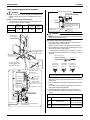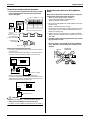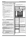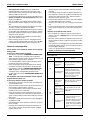
1
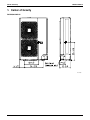
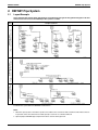
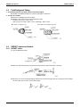
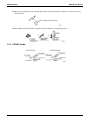
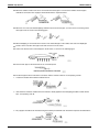
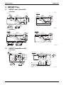
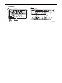
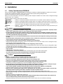
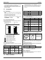
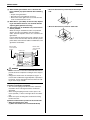
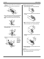
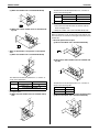
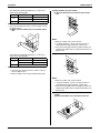
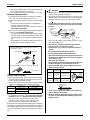
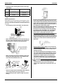
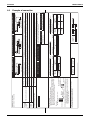
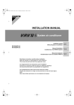
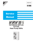
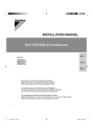
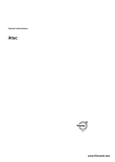
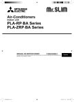
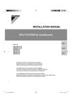
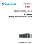
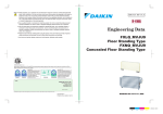
EDUS 39 - 606A - N Installation of Outdoor Units AMERICAS EDUS39-606A-N Installation of Outdoor Units 1. Center of Gravity..................................................................... 2 2. REFNET Pipe System ........................................................... 3 2.1 Layout Example ............................................................... 3 2.2 Field Refrigerant Piping ................................................... 4 2.3 REFNET Joints and Headers .......................................... 4 3. REFNET Pipe ........................................................................ 7 3.1 REFNET Joint (Branch Kit) ............................................. 7 3.2 REFNET Header(Branch Kit) ........................................... 7 4. Installation............................................................................... 9 4.1 Safety Considerations RXYMQ-M .................................... 9 4.2 Introduction ......................................................................11 4.3 Before Installation ............................................................11 4.4 Selection of Installation Location .....................................12 4.5 Refrigerant Piping Work ...................................................17 4.6 Example of connection ....................................................20 4.7 Airtight test and vacuum drying .......................................21 4.8 Electrical Wiring Work ......................................................22 5. Checks after Completion of Work ..........................................26 5.1 Caution for Refrigerant Leaks...........................................28 Installation of Outdoor Units 1 Center of Gravity EDUS39-606A-N 1. Center of Gravity RXYMQ36/48MVJU 4D047387 2 Installation of Outdoor Units EDUS39-606A-N REFNET Pipe System 2. REFNET Pipe System 2.1 Layout Example Use of the particular branch fitting appropriate to each individual unit type not only permits the pipes to be laid with ease but also increases the reliability of the system as a whole. Type of fitting Mixed branch fittings (Piping including both headers and joints) Header branch fitting (Piping consists of REFNET headers only) Line branch fitting (Pipes containing REFNET joints only) Sample systems Units can be added by connecting them directly to the REFNET header or REFNET joint. Further branches cannot be included in the system below the REFNET header branch. Notes 1. When the capacity ratio of the indoor system to the outdoor unit is more than 100% and when all the indoor units are in operation at the same time then the rated capacity of each unit is somewhat reduced. 2. Special purpose REFNET pipe components must be used for all the pipe work Installation of Outdoor Units 3 REFNET Pipe System 2.2 EDUS39-606A-N Field Refrigerant Piping 1. The following materials should be used for all refrigerant piping. Materials: Deoxidized phosphorous seamless copper pipe or equivalent 2. The tips for insulation Both Gas, Liquid piping must be insulated. Materials: Glass fiber or heat-resistant polyethylene foam. Thickness: 1/2 inch (12.7 mm) or more Heat resistance: Gas pipe : 250°F or more / Liquid pipe : 160°F or more Insulation of single pipe only 2.3 Insulation of both liquid and gas pipe REFNET Joints and Headers 2.3.1 REFNET Joints For gas and liquid branch pipes Make sure that all branch pipes are fitted such that they branch either horizontally or vertically. When the size of the selected field piping is different from that of branch pipe then the connecting section should be cut with a pipe cutter as shown in the following figure. 4 Installation of Outdoor Units EDUS39-606A-N REFNET Pipe System When you are cutting an inlet or outlet pipe with a pipe cutter make sure that you make the cut in the center of the connection area. Branch pipes must be insulated in accordance with the handbook accompanying each kit. 2.3.2 REFNET Header Installation of Outdoor Units 5 REFNET Pipe System EDUS39-606A-N When the number of indoor units to be connected to the branch pipes is less than the number of branch pipes available for connection then cap pipes should be fitted to the surplus branches. When the size of the selected field piping is different from that of branch pipe, you must cut the connecting section with a pipe cutter as shown in the following figure: When field piping is connected to the B section of the inlet/outlet pipe on the outdoor unit side of the liquid pipe header, cut the B section with a pipe cutter and connect it to the A section. . Connect the flared section of the field pipe to the B section, as shown in the following figure: Fit the branch pipe so that the branch lies in a horizontal plane. The branch pipe must be insulated in accordance with the instruction manual accompanying each kit. 1. Insulate the header with insulator included in the kit. 2. Joints between insulators included in the kit and those already applied to the field piping should be sealed with the tape accompanying each kit. 3. Any cap pipes should also be insulated using the insulator provided with each kit and then taped as described above. 6 Installation of Outdoor Units EDUS39-606A-N REFNET Pipe 3. REFNET Pipe 3.1 REFNET Joint (Branch Kit) KHRP26M22T (unit:in) Liquid Side Gas Side 1/2 5/8 3/4 Insulation Insulation 5/8 1/2 5/8 1/2 1/4 3 3/8 3 1/4 1-1/2 13-1/3 3/8 3/8 1-1/2 9-7/8 15 11-1/2 7/8 5/8 3/4 3/4 3 4 D3K03622C KHRP26M33T Liquid Side Gas Side Insulation 7/8 3/4 3/4 5/8 1/2 1 3 3 3/8 1/4 1-1/2 10-1/4 7/8 4 4 3.2 1/4 11-13/16 3/4 7/8 3/8 3/8 1-1/2 12-11/16 14-1/4 Insulation 1/2 5/8 D3K03623A REFNET Header(Branch Kit) KHRP26M22H Gas Side Liquid Side Insulation 3/4 Insulation 5/8 1/4 3/8 3 5 1-1/2 5/8 1/2 5 6 2 x 2-1/2 = 5 2-1/2 16 6 2-1/2 2 x 2-1/2 = 5 1/4 1/2 15 1/4 3/8 7/8 4 2-1/2 5/8 4 1/2 3/4 3 3/8 D3K03629B Installation of Outdoor Units 7 REFNET Pipe EDUS39-606A-N KHRP26M33H Gas Side Liquid Side Insulation 3/4 Insulation 5/8 1/4 3/8 1-1/2 3 3-1/4 5/8 6 5 x 2-1/2 = 12-1/2 26 5/8 2-1/2 26 1/2 6 1/4 1/4 5 5 5 2 x 2-1/2 = 5 24 1/2 1/2 1/2 7/8 3/4 3/8 3/8 3-3/4 15 8 2-1/2 6-3/4 3/8 4-3/4 7/8 1/2 5/8 3 4 D3K03630B 8 Installation of Outdoor Units EDUS39-606A-N Installation 4. Installation 4.1 Safety Considerations RXYMQ-M Please read these SAFETY CONSIDERATIONS carefully before installing air conditioning equipment, and be sure to install it correctly. After completing installation, make sure the unit operations properly during startup operation. Instruct the customer how to operate and maintain the unit. Always use a licensed installer or contractor to install this product. Improper installation can result in water or refrigerant leakage, electrical shock, fire, or explosion. Meaning of danger, warning, caution and note symbols. DANGER .............. Indicates an imminently hazardous situation which, if not avoided, results in death or serious injury. WARNING ............ Indicates a potentially hazardous situation which, if not avoided, could result in death or serious injury. CAUTION ............. Indicates a potentially hazardous situation which, if not avoided, may result in minor or moderate injury. It may also be used to alert against unsafe practices that may cause property damage. NOTE.................... Indicates a statement of company policy directly or indirectly related to the safety of personnell or protection of property. DANGER • Refrigerant gas is heavier air and replaces oxygen. A massive leak can lead to oxygen depletion, especially in basements, and an asphyxiation hazard can occur leading to serious injury or death. • Do not ground units to water pipes, telephone wires or lightning rods because incomplete grounding could cause a severe shock hazard resulting in severe injury or death, and to gas pipes because a gas leak could result in an explosion which could lead to severe injury or death. • Do not install unit in an area where flammable materials are present due to risk of explosion resulting in serious injury or death. • Any abnormalities in the operation of the air conditioner such as smoke or fire could result in severe injury or death. Turn off the power and contact your dealer immediately for instructions. • If the refrigerant gas leaks during installation, ventilate the area immediately. Refrigerant gas may produce toxic gas if it comes in contact with fire such as from a fan, heater, stove or cooking device. Exposure to this gas could cause severe injury or death. • After completing the installation work, check that the refrigerant gas does not leak. Refrigerant gas may produce toxic gas if it comes in contact with fire such as from a fan, heater, stove or cooking device. Exposure to this gas can cause severe injury or death. • Do not install the unit in an area where flammable materials are present due to risk of explosion resulting in serious injury or death. • Safely dispose of the packing materials. Packing materials, such as nails and other metal or wooden parts, may cause stabs or other injuries. • Tear apart and throw away plastic packaging bags so that children will not play with them. Children playing with plastic bags face danger of death by suffocation. WARNING • • • • • • • • Perform installation work in accordance with this installation manual. Improper installation may result in water leakage, electric shocks or fire. Be sure to use only the specified accessories and parts for installation work. Failure to use the specified parts may result in water leakage, electric shocks, fire or the unit falling. Install the air conditioner on a foundation strong enough to withstand the weight of the unit. A foundation of insufficient strength may result in the equipment falling and causing injuries. Do not remove the front panel because some parts inside are dangerous to touch. In addition, some parts may be damaged by touching. For checking and adjusting internal parts, contact your dealer. Carry out the specified installation work after taking account of strong winds, typhoons or earthquakes. Improper installation work may result in the equipment falling and causing accidents. Make sure that a separate power supply circuit is provided for this unit and that all electrical work is carried out by qualified personnel according to local laws, regulations and this installation manual. An insufficient power supply capacity or improper electrical construction may lead to electric shocks or fire. Make sure that all wiring is secured, the specified wires are used, and no external forces act on the terminal connections or wires. Improper connections or installation may result in fire. When wiring the power supply and connecting the remote controller wiring and transmission wiring, position the wires so that the electric parts box lid can be securely fastened. Improper positioning of the electric parts box lid may result in electric shocks, fire or the terminals overheating. Installation of Outdoor Units 9 Installation • Before touching electrical parts, turn off the power. • When installing or relocating the system, be sure to keep the refrigerant circuit free from substances other than the specified refrigerant (R-410A) such as air. Any presence of air or other foreign substance in the refrigerant circuit causes an abnormal pressure rise or rupture, resulting in injury. • Do not reconstruct or change the settings of the protection devices. If the pressure switch, thermal switch, or other protection device is shorted and operated forcibly, or parts other than those specified by Daikin are used, fire or explosion may result. • Placing a flower vase or other containers with water or other liquids on the unit could result in a shock hazard or fire if a spill occurs. • Do not touch the switch with wet fingers. Touching a switch with wet fingers can cause electric shock. • Be sure to install a ground leakage breaker. Failure to install a ground leakage breaker may result in electric shocks, or fire. • Heat exchanger fins are sharp enough to cut. To avoid injury wear glove or cover the fins when working around them. • Do not touch the air outlet or horizontal blades while the swing flap is in operation because fingers can get caught and injured. • Do not allow children to play on or around the unit as they could be injured. • Refrigerant pipes may be very hot or very cold during or immediately after operation. Touching them could result in burns or frostbite. To avoid injury give the pipes time to return to normal temperature or, if you must touch them, be sure to wear proper gloves. • While following the instructions in this installation manual, install drain piping in order to ensure proper drainage and insulate piping in order to prevent condensation. Improper drain piping may result in water leakage and property damage. • Be very careful about product transportation. • Do not touch the refrigerant pipes during and immediately after operation. During and immediately after operation, the refrigerant pipes may be hot and may be cold, depending on the condition of the refrigerant flowing through the refrigerant piping, compressor, and other refrigerant cycle parts. Your hands may suffer burns or frostbite if you touch the refrigerant pipes. • Do not remove the front panel because some parts inside are dangerous to touch. In addition, some parts may be damaged by touching them. For checking and adjust internal parts, contact your dealer. • Do not turn off the power immediately after stopping operation. Always wait at least five minutes before turning off the power. Otherwise, water leakage and trouble may occur. • Do not use a charging cylinder. Using a charging cylinder may cause the refrigerant to deteriorate. 10 EDUS39-606A-N • The refrigerant R-410A requires strict cautions for keeping the system clean, dry and tight. A. Clean and dry Foreign materials (including mineral oils such as SUNISO oil or moisture) should be prevented from getting mixed into the system. B. Tight CAUTION • • • • • R-410A does not contain any chlorine, does not destroy the ozone layer, and does not reduce the earth’s protection against harmful ultraviolet radiation. R-410A can contribute slightly to the greenhouse effect if it is released. Therefore we should take special attention to check the tightness of the installation. Read Section 6, REFRIGERANT PIPING WORK carefully and follow these procedures correctly. Since R-410A is a mixed refrigerant, the required additional refrigerant must be charged in its liquid state. (If the refrigerant is charged in a state of gas, its composition changes and the system will not work properly.) The indoor unit is for R-410A. See the catalog for indoor unit models which can be connected. (Normal operation is not possible when connected to other units.) For installation of the indoor units, refer to the installation manual supplied together with each indoor unit. Check the unit stand for damage on a continuous basis, especially if it has been in use a long time. If left in a damaged condition, the unit may fall and cause injury. Never operate the air conditioner with the discharge pipe thermistor (R3T), suction pipe thermistor (R2T) and pressure sensors (S1NPH, S1NPL) removed. Such operation may burn out the compressor. Make sure to provide for adequate measures in order to prevent that the outdoor unit be used as a shelter by small animals. Small animals making contact with electrical parts can cause malfunctions, smoke or fire. Please instruct the customer to keep the area around the unit clean. NOTE • Install the indoor and outdoor units, power supply wiring and transmission wiring at least 3.5 ft. away from televisions or radios in order to prevent image interference or noise. Depending on the radio waves, a distance of 3.5ft. may not be enough to eliminate the noise. • Dismantling of the unit, treatment of the refrigerant, oil and eventual other parts, should be done in accordance with the relevant local and national regulations. • Do not use the following tools that are used with conventional refrigerants: Gauge manifold, charge hose, gas leak detector, reverse flow check valve, refrigerant charge base, vacuum gauge, refrigerant recovery equipment. Installation of Outdoor Units EDUS39-606A-N Installation If the conventional refrigerant and refrigerator oil are mixed in the R-410A, the refrigerant may deteriorated. • Never perform outdoor unit piping connection work when it is raining. 4.2 • The PCI Data Station is a class A product. In a domestic environment this product may cause radio interference in which case the user may be required to take adequate measures. Introduction 4.2.1 Combination 310 Gas (inch) 5/8 Liquid (inch) 3/8 Heating ∗ 115 <c> C Model RXYMQ36MVJU RXYMQ48MVJU Precaution ~ Frequency (Hz) 60 Voltage (V) 208-230 Voltage torerance (%) ±10 Rated current of fuse (A) 30 Phase ∗ <b> 50 43 41 ∗ <a> ∗<c> in the table indicates the operating condition shown in Section 2-3, Technical specifications. Compressor 60 95 Electrical specifications Phase The figures below assume following operating conditions for indoor and outdoor units: Equivalent pipe length ................25 ft. (7.6 m) Level difference...........................0 ft. Cooling Connections Power 4.2.2 Standard operation limit A (lb.) Weight • Always use an appropriate indoor unit compatible with R410A. To learn which models of indoor units are compatible with R-410A, refer to the product catalogs. • Total capacity/quantity of indoor units <Outdoor unit> <Total capacity of indoor units> <Total quantity of indoor units> RXYMQ36MVJU.... 18~46.8 6 units RXYMQ48MVJU.... 24~62.4 8 units 3~ Frequency (Hz) 60 Voltage (V) 208-230 Min. Circuit Amps. (A) 27.0 ∗<c> Accessories 5 23 50 A B C D B 57 67 77 –4 50 82 59 70 81 Confirm that the following accessories are supplied: D Clamp Outdoor temperature (°FDB) Indoor temperature (°FWB) Outdoor temperature (°FWB) Indoor temperature (°FDB) Range for continuous operation Range for pull down operation Range for warming up operation Range for operation Optional accessories RXYMQ36MVJU RXYMQ48MVJU R-410A 208-230V 60Hz Power Cooling capacity (MBh) Heating capacity 36 48 Precaution ∗<a> (MBh) 40 54 ∗<b> Cooling input (kW) 3.05 4.73 ∗<a> Heating input (kW) 3.27 4.26 ∗<b> Dimensions H×W×D 4.3 (inch) (1 pc.) (3 pcs.) In the following table, ∗<a> and ∗<b> indicates the operating condition: Refrigerant Others • Operation manual • Installation manual 4.2.3 Technical specifications Model Insulation tube 52 15/16 × 35 7/16 × 12 5/8 To install the above outdoor units, use the following optional parts: • Refrigerant branching kit* NOTE: Systems using R-410A must have the appropriate kit designed for that system. REFNET joint KHRP26M22T REFNET header KHRP26M22H KHRP26M33H *Select the refrigerant branching kit in accordance with Section 6. REFRIGERANT PIPING WORK. Main components: For main components and function of the main components, refer to the Engineering Data Book. Before Installation Installation of Outdoor Units 11 Installation EDUS39-606A-N Setting the unit in place: Slowly set the outdoor unit in place by holding the handles provided on the left and right sides as shown in the following figures. NOTE • Take care so that hands and objects do not touch the fin on the rear. Be sure to use specified parts and accessories. Discharge grille Outdoor unit 4.4 (Front view) (Rear view) If the suction hole area on the side of the casing is held, the casing may be deformed. Make sure to hold the corner. Lug Selection of Installation Location The refrigerant R-410A itself is nontoxic, nonflammable and is safe. If the refrigerant should leak however, its concentration may exceed the allowable limit depending on room size. Due to this it could be necessary to take measures against leakage. Refer to the chapter Section 5.1 CAUTION FOR REFRIGERANT LEAKS, on page 29. (1) Select a proper location satisfying the following requirements with approval of the customer. • Sufficient ventilation is secured. • Adjacent houses are not negatively affected. • The foundation is strong enough to support the weight and withstand vibrations of the outdoor unit, and the location is safe and allows horizontal installation. • The outdoor unit has minimal exposure to rain. • The space for installation and servicing is secured around the outdoor unit. • The indoor/outdoor piping length and wiring length are within the allowable range. (2) When installing the outdoor unit in a location affected by strong wind, pay special attention to the following items. • If strong wind whose velocity is 5 m/sec or more blows to the outdoor unit from the air outlet side, the airflow rate of the outdoor unit is reduced, the outlet air is sucked again (short-circuited), and the following effects may occur: • Capacity is deteriorated. • Adhered frost increases during heating operation. • Operation is stopped by pressure rise. • If excessively strong wind continuously blows from the air outlet side of the outdoor unit, the fan may rotate in the reverse direction at high speed, and lead to damage. Install the outdoor unit in reference to the following figures. Position the air outlet side toward the building wall, fence or windbreak screen. Suction grille (Secure the space for installation and servicing.) Let the air outlet direction face be at right angles to the wind direction. Strong wind Strong wind Air outlet 12 Installation of Outdoor Units EDUS39-606A-N Installation (3) When installing the outdoor unit in a location with heavy snowfall, pay special attention to the following items: • Prepare strong foundation. • Attach the snow hood (optional accessory). • Remove the suction grill on the rear so that snow will not be accumulated in the rear fin. (4) When there is a possibility of short-circuitry depending on the ambient situation, use the wind direction adjusting plate (optional accessory). (5) The inverter type air conditioner may cause noise in electric products. When selecting an installation location, keep sufficient distance from the air-conditioner units and wiring to radios, personal computers, stereos, etc. as shown in the figure below. In areas with weak electric waves, keep a distance of 120 inches or more from the indoor remote controller, put the power cables and connection cables in conduit tubes, and ground the conduit tubes. Branch switch and overcurrent breaker • When an obstruction is present only on the air inlet side re r 4o mo • When an obstruction is present on both sides 4o rm ore re 4o rm ore r 4o mo Branch switch and overcurrent breaker re 40 or more 40 or mo 60 or m ore Indoor unit Indoor remote controller ore 60 or m ore m r o 60 (in.) DANGER • Do not install unit in an area where flammable materials are present due to risk of explosion resulting in serious injury or death. • Refrigerant is heavier than air and replaces oxygen. A massive leak could lead to oxygen depletion, especially in basements, and an asphyxiation hazard could occur leading to serious injury or death. Installation place (numeric units: inches) 〈Cautions on continuous installation〉 • The connection piping outlet direction in the continuous installation shown in the figures below is frontward or downward. • When routing the piping rearward, secure space of 10 inches (254 mm) or more on the right side of the outdoor unit. • Make some space for wiring with conduit and servicing between the units. (A) When an obstruction is present on the air inlet side • When the upward area is open (1) When one outdoor unit is installed individually Installation of Outdoor Units 13 Installation EDUS39-606A-N (2) When two or more outdoor units are installed side by side • When an obstruction is present on the both sides 40 or (B) When an obstruction is present on the air outlet side • When the upward area is open (1) When one outdoor unit is installed individually mo re ore rm ore 8o rm rm o 12 ore o 20 (2) When two or more outdoor units are installed side by side 20 ess or l 40 or more • When an obstruction is present also in the upward area (1) When one outdoor unit is installed individually • When an obstruction is present also on the air inlet side • When an obstruction is also present in the upward area (1) When one outdoor unit is installed individually ore rm 4o s r les 40 or more 20 o • When an obstruction is present also on the air inlet side and both sides ess or l 40 or more 20 ore rm o 40 ore rm o 20 rm ore 6o ore rm 6o rm ore (2) When two or more outdoor units are installed side by side s r les 20 o 40 or more (2)When two or more outdoor units are installed side by side •When an obstruction is present on ss e l or both sides, 20 plus the air inlet side 40 or more 6o 40 or m ore ore 8o ore rm rm ore o 12 40 or m (C) When an obstruction is present on both the air inlet and air outlet sides <Pattern 1> When an obstruction on the air outlet side is higher than the outdoor unit. . There is no height restriction on the air inlet side. • When the upward area is open 14 Installation of Outdoor Units EDUS39-606A-N Installation re mo H<L L L≤H r L>H 20 or 4o re mo L A 0 < L ≤ 1/2H 40 1/2H < L ≤ H 50 Install the frame to achieve “L ≤ H”. NOTE: H L (2) When two or more outdoor units are installed side by side ore L>H The dimensional relationship between H, L, and A is as shown in the following table: H (1) When one outdoor unit is installed individually ore 12 1. Close the area under the frame so that the outlet air does not bypass there. 2. Only two outdoor units can be installed side by side. <Pattern 2> When an obstruction on the air outlet side is lower than the outdoor unit. There is no restriction in the height of obstruction on the air inlet side. • When the upward area is open (1) When one outdoor unit is installed individually or m H rm • When an obstruction is also present in the upward area (1) When one outdoor unit is installed individually L≤H L o 40 s r les 2 (2) When two or more outdoor units are installed side by side L H L 40 or more 20 o ore rm 4o ore m r 0o H ore 10 or m A The dimensional relationship between H, L, and A is as shown in the table below. H<L A 0 < L ≤ 1/2H 30 1/2H < L ≤ H 40 Install the frame to achieve L ≤ H. • Close the area under the frame so that the outlet air does not bypass there. (2) When only two outdoor units are installed side by side 6 The dimensional relationship between H, L, and A is as shown in the following table: L A 0 < L ≤ 1/2H 10 1/2H < L ≤ H 12 • When an obstruction is present also in the upward area (1) When one outdoor unit is installed individually s r les 20 ess or l L L H 40 or more 20 o A 40 or more L≤H L ore rm 0o H ore rm 2o 1 ore A rm 0o 4 A Installation of Outdoor Units 15 Installation EDUS39-606A-N The dimensional relationship between H, L and A is as shown in the following table: L≤H H<L L A 0 < L ≤ 1/2H 4 1/2H < L ≤ H 8 (D) When outdoor units are stacked (1) When an obstruction is present on the air outlet side Z Install the frame to achieve L ≤ H. 4 NOTE: • Close the area under the frame so that the outlet air does not bypass there. (2) When only two outdoor units are installed side by side ore ess 40 or more rl 0o L H 2 ore A rm 0o 6 The dimensional relationship between H, L and A is as shown in the following table: L≤H H<L L A 0 < L ≤ 1/2H 10 1/2H < L ≤ H 12 40 or m NOTE: 1. Only two outdoor units can be stacked. 2. For drain treatment, a space of at least 4 inches is required between upper and lower outdoor units. 3. Close the area Z (gap between the upper outdoor unit and the lower outdoor unit) so that the outlet air does not bypass there. (2) When an obstruction is present on the air inlet side Z Install the frame to achieve L ≤ H. 4 NOTE: 1. Close the area under the frame so that the outlet air does not bypass there. 2. Only two outdoor units can be installed side by side. ore 12 or m NOTE: 1. Only two outdoor units can be stacked. 2. For drain treatment, a space of at least 4 inches is required between upper and lower outdoor units. 3. Close the area Z (gap between the upper outdoor unit and the lower outdoor unit) so that the outlet air does not bypass there. (E) When outdoor units are installed in rows, such as on a rooftop. (1) When one outdoor unit is installed in each row 4 or e mor ore rm 80 o r 40 o 16 e mor 8 or e mor Installation of Outdoor Units EDUS39-606A-N Installation • For drain treatment, a space of at least 4 inches is required under the bottom frame of the outdoor unit. • In the drain piping work, make sure that drainage is discharged securely. When routing the piping downward, check for water leakage. <Transport fitting removal procedure> L Air outlet side 4 5/8 or 8 5/8 120 11 3/8 H ore r 24 o e mor 24 3/8 5 1/2 Bottom view (unit: inch) rm 60 o 1 3/4 The dimensional relationship between H, L, and A is as shown in the table below. L≤H H<L L A 0 < L ≤ 1/2 H 10 1/2 H < L ≤ H 12 Installation is not allowed. CAUTIONS ON INSTALLATION Washer 15/16 <Drain treatment> • In a location where drain from the outdoor unit may cause problems, for example, where drainage may splash on general passersby, perform the drain piping work using the optional drain plug. 4.5 16 5/8 24 1/8 Drain hole • Transport fittings (YELLOW ones in two positions) are provided on the leg of the compressor for protectingthe unit during transport. Remove them as instructed in the following figure: Compressor • Before installation, confirm the strength and levelness of the foundation so that vibrations and noise are not generated. • Fix the outdoor unit securely on a rigid base with foundation bolts as shown in the following foundation drawing. • Prepare four sets of commercially available M12-type or equivalent foundation bolts, nuts and washers. • Use resin washers to prevent the paint from being scratched off and rusting. • The foundation bolts should be protruded by 15/16 inches. (Refer to the following figure) (13 5/8-14) 5 1/2 A e mor 13 3/4 (2) When two or more outdoor units are installed side by side Fixing nut (Loosen the nut slightly. Then, the fitting can be removed.) Noise-proof cover Transport fitting Transport fitting Turn it in the arrow direction, and remove it. 1. Open the noise-proof cover as shown in the figure above. At this time, do not pull the noise-proof cover, and do not remove it from the compressor. 2. Slightly loosen each fixing nut. 3. Remove each transport fitting as shown in the figure above. 4. Tighten each fixing nut again. 5. Close the noise-proof cover to achieve the former status. NOTE: • If the unit is operated with the transport fittings attached, abnormal vibration or sound may be generated. Refrigerant Piping Work • <To piping technician> Make sure to open the stop valves after finishing the piping work. Refer to the table shown in Section 6-8, Additional Refrigerant Charge. Operating the air conditioner with the stop valve shut may damage the compressor. • Use R-410A which is contained in a pink cylinder. All field piping must be installed by a licensed refrigeration technician and must comply with relevant local and national regulations. • BRAZING REFRIGERANT PIPING Do not use flux when brazing copper-to copper refrigerant piping, particularly for HFC refrigerant piping. Use phosphor copper brazing filler metal (BCuP) which does not require flux. Installation of Outdoor Units Flux has an extremely negative effect on refrigerant piping systems. For instance, if chlorine based flux is used, it will cause pipe corrosion. If the flux contains fluorine, it will damage the refrigerant oil. NOTE: • Installation tools: Make sure to use installation tools, such as a gauge manifold charge hose, that are exclusively used for R-410A installations to withstand the pressure and to prevent foreign materials, for example SUNISO mineral oils or moisture, ( from mixing into the system. The screw specifications differ for R-410A and R407C. Use a 2-stage vacuum pump with a non-return valve. 17 Installation EDUS39-606A-N 1. Foreign materials inside pipes (including oils for fabrication) must not exceed 9 mg per 10 feet or less. 2. Use the following material specification for refrigerant pipping: • Construction material: Phosphoric acid deoxidized seamless copper for refrigerant. • Size: Determine the proper size referring to Section 66, Example of Connection. 3. Make sure to use the refrigerant branching kit designated in Section 6-6, Example of Connection. • Use this guide to perform the piping installation within the range of the maximum allowable pipe length, allowable level difference, and allowable length after branching. • For installation of the refrigerant branching kit, refer to the installation manual attached to the kit. Install the REFNET joint so that the pipings are branched horizontally or vertically. (Horizontal line) Within ± 30° (View A) Or vertically A Mount the REFNET header so that it branches horizontally. (Horizontal line) (View B) B PROTECTION OF PIPING: • Protect piping to prevent moisture and dust from entering, especially when passing pipes through a hole or connecting the end pipe that extends outside. • Especially, pay attention when passing the pipings through a hole or connecting the end of piping to the outdoor. Location Outdoor Indoor Working period Protection method 1 month or more Pinch pipes Less than 1 month Regardless of period Pinch or tape pipes Piping connection • For handling of stop valves, refer to Stop valve operation method in Section 6-7, Airtight test and vacuum drying. • Only use the flare nuts attached to the stop valves. Using different flare nuts may cause the refrigerant to leak. • Be sure to perform a nitrogen blow when brazing. Brazing without performing nitrogen replacement or releasing nitrogen into the piping will create large quantities of oxidized film inside the pipes, adversely affecting valves and compressor in the refrigerating system and preventing normal operation. 18 • Use of oxygen could cause an explosion resulting in severe injury or death. Only use nitrogen gas. • Refrigerant gas may produce toxic gas if it comes in contact with fire such as from a fan heater, stove, or cooking device. Exposure to this gas can cause severe injury or death. • When brazing with blowing nitrogen, set the nitrogen pressure to 2.9 psi or less by using a pressure reducing valve. Refrigerant piping Location to be brazed Regulator Nitrogen Taping Manual valve Nitrogen • Do not use anti-oxidants when brazing. Residue can clog pipes and break the unit. • Do not let any refrigerant other than the specified refrigerant enter the refrigerant system. • Do not let any gas, such as air, enter the refrigerant system. Precautions when connecting the pipings: • See the following table for flare dimensions. • When connecting the flare nuts, apply refrigerant oil to the inside and outside of the flares and turn them three or four times at first. (Use ester oil or ether oil.) • See the following table for tightening torque. Applying too much torque may cause the flares to crack. • After connecting all the pipings, perform a gas leak check by using nitrogen. Pipe size φ3/8” Tightening Flare dimension A (in.) torque ft·lbf 24.1’-29.4’ (9.5mm) (7.35 – 8.96 m) φ5/8” 45.6’-55.6’ (15.88mm) (13.90 -16.95m) 0.504 - 0.520 (12.80-13.21mm) Flare shape (in.) R0.016 ~0.031 A Selection of piping material DANGER 90°± 2° 45° ± 2° 1. Make sure the pump oil does not flow oppositely into the system while the pump is not working. 2. Use a vacuum pump which can evacuate to –14.6 psi. 0.760 - 0.776 (19.30-19.71mm) Refrigerant oil • If you must install the unit without a torque wrench, use the following instructions: . • When you keep on tightening the flare nut with a spanner, there is a point where the tightening torque suddenly increases. Installation of Outdoor Units EDUS39-606A-N Installation • From that position, further tighten the flare nut the angle shown below. Tightening angle (Guideline) Pipe size φ 3/8” Recommended arm length of tool (in.) Approx. 7 7/8” 60°~90° (9.5mm) φ 5/8” (15.88mm) (197.62mm) Approx. 11 13/16” (300.04mm) 30°~60° • After the work is finished, make sure there is no gas leak. Disposal requirements Dismantling of the unit and treatment of the refrigerant, oil, and other parts should be comply should be in compliance with the relevant local and national regulations. Refrigerant piping work procedure: • The field piping can be connected in four directions. Front panel Piping cover Rear direction Screw for front panel Front direction Screw for piping cover (front) Downward direction Lateral direction • When connecting the piping in the lateral direction (on the rear), remove the piping cover (rear) and receiver mounting plate in reference to the figure below. Receiver mounting plate Piping cover (rear) • When connecting the pipings downward, remove the knockout by making four holes in the middle on the each side of the knockout with a drill. • Ensure that the field pipings do not touch the terminal cover of the compressor. Especially when the insulation provided on the liquid piping touches the terminal cover, adjust its height as shown in the figure above. Make sure that the piping does not touch the bolts of the compressor and the outer panels. • When it is expected that condensed water in the stop valve will reach the indoor unit through the gap between the heat insulating material and the piping (for example, when the outdoor unit is installed in a higher position than the indoor unit), take proper action such as caulking the connection area. • To prevent invasion of small creatures and litter: Block all gaps in the piping penetration areas with putty or heat insulating material (arranged in teh local field) as shown in the figure below. If insects or litter enters the outdoor unit, a short circuit in the electric parts box may result. • Heat Insulation of piping: Make sure to insulate the field pipings (on both liquid and gas lines) and refrigerant branching kit. If they are not insulated, water leakage can result. • The maximum temperature of the piping on the gas line is about 2480F during heating operation. Use an insulation sufficiently resistant to this temperature. • Reinforce the refrigerant piping according to the installation environment. If it is not reinforced, condensate may form on the surface of the insulation. CAUTION Drill • Make sure to insulate the field piping up to the piping connection area inside the unit. If the piping is exposed, dew condensation and contact burns can result. Middle on the side Knockout Slit Field pipings Slit Bottom frame • Then cut out the corner of the bottom frame along the slits (in two positions) by using a hacksaw. • After removing the parts, paint the edges to prevent rusting. Installation of Outdoor Units 19 20 2 c g C 3 d h D 4 H2 5 H1 i H1 h H2 1 c 2 d 3 e 4 H2 5 f H1 How to calculate the additional refrigerant to be charged Additional refrigerant to be charged R (lb.) R should be rounded off in units of 0.1(lb.). Caution) In brazing connection in the size increase area in the piping, use a different-diameter joint for connection. (The different-diameter joint should be procured in the field.) The connection area is located near the outdoor unit (usually after the first bending outside the unit). (Max 130 ft. if the outdoor unit is below) Refrigerant branching kit name R= Total length (ft.) of liquid piping size at φ3/8” x 0.036 + Total length (ft.) of liquid piping size at φ1/4” x 0.015 Gas pipe φ5/8 (Unit: in.) φ1/2 φ 5/8 24,30,36,48 type φ3/8 φ1/4 Piping size (outer diameter) Gas pipe Liquid pipe 12,18 type Indoor unit capacity type 0 R= (a+b)×0.036 + (c+d+e+f+g+h)×0.015 = 7.98 ? 8.0 Example for refrigerant branch using REFNET joint and REFNET header φ × 30ft. The piping a: ?φ 3/8 × 100ft. d: ?1/4 g: φ 1/4 × 30ft. lengths are as φ × 30ft. b: ?φ 3/8 × 30ft. e: ?1/4 h: φ 1/4 × 70ft. at right c: ?φ 1/4 × 30ft. f : φ 1/4 × 30ft. Liquid pipe φ3/8 Piping size (outer diameter) Refrigerant branching kit name KHRP26M22H (Max. 4 branch) KHRP26M33H (Max. 8 branch) Between Refrigerant branching kit and indoor unit • Pipe size for direct connection to indoor unit must be the same as the connection size of indoor unit. (Unit: in.) Indoor unit connection pipe size Outdoor unit capacity type RXYMQ36,48 type Piping between Refrigerant branching kits • Use the pipe size from the following table. Connection pipe size Example unit 5: f ≤ 130 ft. How to select the REFNET header • Choose from the following table below the REFNET header according to the number of indoor units on the system. Example unit 3: b + e ≤ 130 ft., unit 5:f + h ≤ 130 ft. KHRP26M22T Piping between outdoor unit and Refrigerant branching kit • Match to the size of the connection piping on the outdoor unit. RXYMQ36,48 type Outdoor unit capacity type Use REFNET joint from the following table. Example unit 5: b + c + d + i ≤ 130 ft. Pipe length from first refrigerant branching kit (either REFNET joint or REFNET header ) to indoor unit ≤ 130 ft. • When the equivalent piping length between the outdoor unit and the indoor units is Outdoor unit connection pipe size (Unit: in.) 295 ft. or more, make sure to use a thicker pipe as the main pipe on the gas line. When the air-conditioning capacity is reduced due to the refrigerant piping Piping size distance, a thicker pipe may be used also as the main pipe. Outdoor unit (outer diameter) capacity type [Gas side] Gas pipe Liquid pipe RXYMQ36,48 type φ5/8” ® φ3/4” φ5/8 RXYMQ φ3/8 The first refrigerant 36,48 type φ3/4 branching kit Main pipe Outdoor unit Enlarge Indoor unit Actual pipe length Difference in height between adjacent indoor units (H2) ≤ 49 ft. Difference in height Total piping length from outdoor unit to all indoor units ≥33 ft., ≤ 1000 ft. Example unit 5: a + f ≤ 492 ft. Indoor units (1-5) b Total extension length Between indoor and indoor units Pipe size selection áCaution on selecting connection pipesñ 5 Example unit 3: a + b + e ≤ 400 ft., unit 5: a + f + h ≤ 492 ft. Difference in height between outdoor and indoor units (H1) ≤ 164 ft. Refrigerant branching kits can only be used with R-410A. 3 4 REFNET header Equivalent piping length between outdoor and indoor units ≤ 580 ft. (assume equivalent pipe length of REFNET joint to be 0.5m, that of REFNET header to be 1m, calculation purposes) Difference in height Refrigerant branching kit selection 2 g e a Outdoor unit Branch with REFNET header Equivalent length Example unit 5: a + b + c + d + i ≤ 492 ft. 1 d B A b f REFNET joint (A • B) Indoor units (1-5) c REFNET header Pipe length between outdoor and indoor units ≤ 492 ft. Indoor units (1-5) f 1 B e b A a Outdoor unit Branch with REFNET joint and REFNET header Between outdoor and indoor units Allowable length after the branch Allowable height length Between outdoor and indoor units Actual pipe length a Outdoor unit REFNET joint (A-D) Branch with REFNET joint 4.6 Maximum allowable length Example of connection (Connection of 5 indoor units) Installation EDUS39-606A-N Example of connection Installation of Outdoor Units Installation 4.7 Airtight test and vacuum drying All units are checked for leaks by the manufacturer. Confirm that the valves are firmly closed before airtight test or vacuum drying. To prevent entry of any impurities and ensure sufficient pressure resistance, always use the special tools designated for R-410A. Perform the following inspections securely after the piping work. • Airtight test - Make sure to use nitrogen gas. For the service port position, refer to the figure following the Stop valve operation method instructions. [Procedure] Pressurize the air conditioner from the liquid pipe and gas pipe up to 550 psi making sure not to exceed 550 psi. When the pressure does not drop for 24 hours, the piping work shall be accepted. If the pressure drops, check for leakage positions. (Confirm that there is no leakage, then release nitrogen.) • Vacuum drying - Use a vacuum pump which can evacuate up to –14.6 psi or less. [Procedure] Operate the vacuum pump for evacuation for 2 hours or more using both liquid pipe and gas pipe until the vacuum pressure reaches –14.6 psi or less. Leave the air conditioner at –14.6 psi or less for one hour or more, and confirm that the vacuum pressure indicated by the vacuum gage does not increase. If the vacuum pressure increases, the system may contain moisture or have leakage. If there is a possibility of moisture remaining in the piping: For example, when there is a possibility of dew condensation inside the piping because the piping work was performed in the rainy season or over a long period of time, or when rainwater may have entered the piping during the work. Perform evacuation described above for 2 hours (vacuum drying), pressurize the air conditioner up to 7 psi (vacuum break) with nitrogen gas, then evacuate the air conditioner using the vacuum pump for 1 hour to achieve –14.6 psi or less (vacuum drying). If the vacuum pressure does not reach –14.6 psi or less even after evacuation for 2 hours or more, repeat vacuum break and vacuum drying. Leave the air conditioner in the vacuum status for 1 hour or more, and confirm that the vacuum pressure indicated by the vacuum gauge does not increase. Additional refrigerant charge WARNING Fill with the tank upright. There is a siphon tube inside, so there is no need to turn the tank upside-down. Other ways of filling the tank Fill with the tank upside-down. • Determine the amount of refrigerant to be added by referring to the table in Section 6-6 Example of Connection, write it down on the label on the back side of the front cover. • After the vacuum drying is finished, charge the additional refrigerant in its liquid state through the liquid stop valve service port. Taking into account following instructions: 1. Check that gas and liquid stop valves are closed. 2. Charge the specified amount of refrigerant. • If the outdoor unit is not in operation and the total amount cannot be charged, follow the procedures for additional refrigerant charge shown below. • Make sure to use installation tools you exclusively use on R-410A installations to withstand the pressure and to prevent foreign materials from mixing into the system. • Procedures for charging additional refrigerant. Pressure reducing valve Outdoor unit R-410A Cylinder • Refrigerant cannot be charged until field wiring has been completed. Refrigerant may only be charged after performing the airtight test and the vacuum drying previously described. How to fill a tank with a siphon attached. (Siphon system) NOTE When charging refrigerant into the system, take care that its maximum allowable charge is never exceeded, in view of the danger of liquid hammer. Refrigerant containers shall be opened slowly. To avoid compressor breakdown, do not charge the refrigerant more than the specified amount to raise the condensing pressure. • This outdoor unit is factory charged with refrigerant and depending on pipe sizes and pipe lengths some systems require additional charging of refrigerant. • Charge the refrigerant to the liquid pipe in its liquid state. Since R-410A is a mixed refrigerant, its composition changes if charged in a state of gas and normal system operation would no longer be assured. • Before filling, check whether the tank has a siphon attached or not. Nitrogen • To avoid injury, always use protective gloves and eye protection when charging refrigerant. • To avoid injury, do not charge with unsuitable substances. Use only the appropriate refrigerant. 21 EDUS39-606A-N Weighing scale Liquid line Dotted lines represent field piping Gas line Indoor units Valve A Vacuum pump Stop valve service port Charge hose See the SERVICE PRECAUTIONS label on the back of the front panel for the settings for operation after replenishing refrigerant. Installation of Outdoor Units EDUS39-606A-N Installation 1. Open the gas line stop valve (leaving the liquid line stop valve, valve A in the diagram above, close) and perform the operation to add the refrigerant. 2. Once the appropriate amount of refrigerant is in, press the confirmation button (BS3) on the outdoor unit PC board (A1P), and stop operation.Open the stop valves quickly (both liquid and gas line valves).(This must be done quickly to avoid the possibility that the pipe might burst.) 3. Stop Valve Operation Method Cautions: • The figure below shows the name of each part required in handling the stop valve. At the time of shipment, the stop valve is closed. • If only a torque wrench is used to loosen or tighten the flare nut, the side plate may be distorted. Make sure to fix the stop valve with a spanner, then loosen or tighten the flare nut with a torque wrench. • When it is expected that the operating pressure will be low (for example, when cooling will be performed while the outside air temperature is low), sufficiently seal the flare nut in the stop valve on the gas line with silicon sealant to prevent freezing. • Prepare hexagon wrenches .2 and .3 inches. How to open the stop valve 1. Insert a hexagon wrench into the valve stem, and turn the valve stem counterclockwise. 2. When the valve stem cannot be turned any more, stop turning. Now, the valve is open. How to close the stop valve 1. Insert a hexagon wrench into the valve stem, and turn the valve stem clockwise. 2. When the valve stem cannot be turned any more, stop turning. Now, the valve is closed. Cautions Handling the Valve Cap: • The valve is sealed in the arrow area. Take care not to damage the arrow area. Valve cap Stop valve (valve cap attachment area) • After handling the valve, make sure to tighten the valve cap securely. Liquid line Gas line 10.0~12.2 ft·lbf 16.6~20.3 ft·lbf Use the following precautions handling the service port: • Use charge hose equipped with push in the work. • After the work, make sure to tighten the valve cap securely. Tightening torque.....8.5~10.3 ft·lbf Note: Do not apply force to the valve cap. Using a spanner on the valve cap and the valve body could cause a refrigerant leak. Spanner prohibition to valve cap and body part Spanner Torque wrench Stop valve of two hangs stucture Torque wrench Stop valve of one hangs stucture Service port Valve stem Silicon sealant Valve cap (Take care not to generate cavity.) Field piping connection part 4.8 Opening direction Opening direction <Liquid line> <Gas line> Electrical Wiring Work DANGER • Do not ground units to water pipes, telephone wires, or lightning rods because incomplete grounding could cause a severe shock hazard resulting in severe injury or death, and to gas pipes because a gas leak could result in an explosion which could lead to severe injury or death. Installation of Outdoor Units WARNING • Disconnect all power to unit to avoid possible electric shock during installation. Use only specified wire and connect wires to terminals tightly. Be careful that wires do not place external stress on terminals. Keep wires in neat order so as to not to obstruct other equipment. Incomplete connections could result in overheating, and in worse cases, electric shock or fire. For details see Power Supply Wiring Connection Procedure. 22 Installation CAUTION EDUS39-606A-N Connection example of whole system wiring Power • Do not operate the air conditioner until the refrigerant piping work is completed. Operating the air conditioner before the refrigerant piping work is completed may damage the compressor. • Install a ground leakage circuit breaker. The inverter is provided in the air conditioner. In order to prevent malfunction of the a ground leakage circuit breaker itself, use a breaker resistant to higher harmonics. • Electricians having sufficient knowledge should perform the electrical wiring work. All wiring must comply with local electrical codes and National Electrical Code (NEC). • Perform the electric wiring work in accordance with the ELECTRIC WIRING DIAGRAM label. • Make sure to turn OFF the branch switch and overcurrent breaker before starting the work. • Perform grounding to the indoor units and outdoor units. • Use only copper wires. • Make sure to turn the power off before starting the electric wiring work. Do not turn ON any switch until the work is completed. • The outdoor unit has an inverter which generates noise and charges the outer casing with the leakage current. The outdoor unit should be grounded so that the effect of the generated noise on other equipment can be reduced, and the outer casing can be discharged. • As this unit is equipped with an inverter, installing a phase advancing capacitor will not only reduce the power factor improvement factor, but may also cause the capacitor to overheat due to high-frequency waves. Therefore, never install a phase-advancing capacitor. • Never push excessive electric wires into the units. • Protect electric wires with conduit tubes or vinyl tubes so that they will not be damaged by edges of knockout holes. • Fix electric wires with clamps as accessories so that they will not come into contact with pipes and stop valves. Refer to Section Power supply wiring connection procedure. 23 Outdoor unit Earth leakage circuit breaker Branch switch Overcurrent breaker (fuse) 208-230V Ground 16V Power 208-230V Indoor unit 16V Ground 16V 16V Remote controller Routing power supply wiring and transmission wiring Let the power supply wiring with a conduit pass through one of the knockout holes on the front or side cover, and let the transmission wiring with a conduit pass through another knockout hole. • For protection from un-insulated live parts, thread the transmission wiring through the included insulating tube and secure it with the included clamp. Insulating tube (accessory) Clamp (accessory) Transmission wiring (3in.) Precautions when knocking out knock holes: • To punch the knockout hole, hit it with a hammer. • After removing the knockout, paint the edges to prevent rusting. • Use conduit for both the power supply wiring and transmission wiring. • Outside the unit, make sure to keep the wirings five inches away or the outdoor unit may be affected by external electrical noise and malfunction or fail. • Be sure to connect the power supply wiring to the terminal block and secure it as described in Section Power supply wiring connection procedure. • Fix the wiring between the units in accordance with Section Transmission wiring connection procedure. • To prevent wires from touching the piping, secure them with the accessory clamps. • Make sure the wirings will not be pinched by the front panel, and close the panel firmly. • Route the conduit along the unit by using a elbow socket to prevent it from being stepped on. Installation of Outdoor Units EDUS39-606A-N Installation Power supply wiring connection procedure When using shield wire WARNING Cable clamp (Copper foil is provided.) • Never connect power supply wiring to the terminal block for remote controller wiring as this could damage the entire system. Install a ground leakage circuit breaker. • You must install a ground leakage circuit breaker to prevent electric shock and fire accident. Model RXYMQ36MVJU RXYMQ48MVJU Phase and frequency Voltage ~ 60Hz 208-230V Screw Shield Fix the shield area of the unitto-unit wiring to the copper foil area of the clamp. Rated current Min. Circuit of fuse Amps. 30A Transmission wiring between units 27A arrow view CAUTION Electric parts mounting plate • After finishing the electrical wiring work, confirm that all the wirings are connected securely. A1P Power supply wiring (including ground wire) or Transmission wiring Stop valve mounting plate Precautions when laying power wiring: • Two electric wires of different thickness cannot be connected to the power terminal block. Slack in the electric wires may generate abnormal heat. • Use round pressure terminals with insulting sleeve for connection to the power terminal block. If round pressure terminals are not available, connect an electric wire of the same thickness to each side as shown in the figure. Attach insulation sleeve Power wire Round pressure terminal Lock nut Power supply wiring (including ground wire) or Transmission wiring Conduit Power supply wiring F2 F1 F2 TO IN/D UNIT TO OUT/D UNIT Control terminal block (X1M) Power terminal block (X1M) It is forbidden to connect two to one side. It is forbidden to connect wiring of different thicknesses. Transmission wiring between units ∗ F1 C B C/H SELECTOR A Control PC board (A1P) Ground wiring (yellow/green) Connect samethickness wiring to both sides. Cover When using a shield wire Clamp (accessory) Pass the wiring through the clips. • • Insulating tube (accessory) • • L1 L2 Terminal block You must observe the following instructions or abnormal heat may be generated by slack in electric wires. For wiring, use the designated power wire and connect firmly, then secure to prevent outside pressure on the terminal board. Use an appropriate screwdriver for tightening the terminal screws. A screwdriver with a small head will strip the head and make proper tightening impossible. Over-tightening the terminal screws may break them. See the table below for tightening torque for the terminal screws. Tightening torque Clamp (accessory) ∗ This clamp is unnecessary when not using shield wire. Installation of Outdoor Units M5 (Power supply and ground terminal block) 1.76 ~ 2.15 ft-lbf (536..4 ~ 655.32 mm)-lbf M4 (Shielded ground) 0.87 ~ 1.06 ft-lbf (265.17 ~ 323.09 mm-lbf) M3.5 (Transmission wiring terminal block) 0.58 ~ 0.72 ft-lbf (176.74 ~ 219.46 mm)-lbf 24 Installation EDUS39-606A-N Transmission wiring connection procedure • If excessive force is applied while connecting a cable to the terminal block on the PC board, the PC board may be damaged. A1P A A B C F 1 F2 F1 F 2 B C F1 F2 F1 F2 ABC C/H SELECTOR Cool/heat selector TO IN/D UNIT TO OUT/D UNIT Outdoor unit PC board (A1P) Take care of the polarity Use the conductor of sheathed wire (2 wire) (no polarity) F1 F2 F1 F2 F1 F2 F1 F2 F1 F2 Terminal board (field supply) Indoor unit Setting the cooling/heating operation • Performing cool/heat setting with the remote controller connected to the indoor unit. Keep the cool/heat selector switch (DS1) on the outdoor unit PC board (A1P) at the factory setting position on the indoor unit. Restrictions and Cautions for Wiring between Units: Make sure to observe the restrictions below. If they are not observed, transmission error may occur. Maximum wiring length: 3280 ft. (1000 m) Total wiring length: 6560 ft. (2000 m) or less Maximum number of branches: 5 • Never connect 208-230V to the terminal block for the transmission wiring. Doing so will break the entire system. • The transmission wiring from the indoor units must be connected to the F1/F2 ( to indoor unit) terminals on the PC board in the outdoor unit. • ∗Make sure to use sheathed two-core cables of AWG18.. Only the cool/heat selector remote controller can use a triaxial cable. ∗ All cables used in the wiring between the units should be procured on the site. • Up to 5 branches are available in the wiring between units. However, sub-branching from a branch is not allowed. Branch F1 F2 TO IN/D UNIT F1 F2 F1 F2 F1 F2 F1 F2 F1 F2 O U T ON DS1 OFF 1 I N F1 F2 Sub-branch after branch P1 P2 2 3 4 P1 P2 Remote controller • Performing cool/heat setting with the cool/heat selector. Connect the cool/heat selector remote controller (optional) to the A/B/C terminals and set the cool/heat selector switch (DS1) on the outdoor unit PC board (A1P) to outdoor unit. . O U T ON ABC ABC DS1 OFF 1 I N 2 3 4 Cool/heat selector CAUTION • For low-noise operation, you must install the optional External Control Adaptor for the Outdoor Unit. For details, see the installation manual attached to the adaptor. 25 Installation of Outdoor Units EDUS39-606A-N Checks after Completion of Work 5. Checks after Completion of Work DEMAND H7P H5P ON H6P H4P OFF L.N.O.P SLAVE Installation of Outdoor Units MASTER • Make sure to perform the check operation after installation. If the air conditioner is operated using the indoor remote controller without performing the check operation, the mal- H3P Power on and check operation C/H SELECTOR NOTE One outdoor unit installed LED display: H2P Cautions before turning on the power: • Put the insulating cover securely onto the electric parts box. • After turning on the power, check the settings and LED indicators on the PC board (A1P) in the outdoor unit through the opening of the insulating cover. LED display (Default status before delivery) IND WARNING • Make sure to close the outer panel before leaving the outdoor unit in the power ON status. • To avoid injury, always make sure that the circuit breaker on the power supply panel of the installation is switched off before doing any work. Make sure to turn on the power 6 hours Caution before starting operation for supplying the power to the crankcase heater. (2) • Open the outer panel of the outdoor unit. • Check the LED on the PC board (A1P) in the outdoor unit to see if the data transmission is performed normally. H1P • Make sure to open the stop valve after finishing the piping work as operating the air conditioner with the stop valve shut may damage the compressor. • TEST OPERATION PROCEDURE A crankcase heater is mounted for smooth startup. Make sure to turn on the power 6 hours before starting operation for supplying the power to the crankcase heater. (1) • Close the outer panel of the outdoor unit. • Turn ON the power to the outdoor unit and indoor units. MODE <To piping technician> In the check operation, the status of the outdoor unit and any possible incorrect wiring is checked. TEST/HWL CAUTION function code [U3] is displayed in the indoor remote controller, and normal operation is disabled. SERVICE MONITOR HAP After completing the work, make sure to confirm the following items: 1. Connection of drain piping and removal of transport fittings: Refer to Section 5. CAUTIONS ON INSTALLATION. 2. Connection of power supply wiring and tightening of screws: Refer to Section 7-3 Power supply wiring connection procedure. 3. Connection of transmission wiring and tightening of screws: Refer to Section7-4 Transmission wiring connection procedure. 4. Freezing connection of refrigerant piping Refer to Section 6. REFRIGERANT PIPING WORK. 5. Piping size and heat insulation: Refer to Section 6-1 Selection of piping material, Section 6-5 Heat insulation of the piping. 6. Check of stop valve: Confirm that the stop valve is open on both the liquid line and gas line. 7. Record of amount of additional refrigerant: Record the amount on the label stuck on the back of the front panel. 8. Measurement of insulation in main power circuit: • Use the MegOhm Meter for 500 V. • Do not use any MegOhm Meter for low voltage electric circuits except 230 V wiring between the outdoor and indoor units. The power is supplied to the outdoor unit. Take due care during the work to prevent electric shock. Blinking (3) • When performing the • The power is supplied to the outdoor low-noise operation unit. Take due care during the work to (L.N.O.P.) or demand prevent electric shock. (DEMAND) operation • Before using the pushbutton switches upon request from the (BS1 to BS5) for setting, confirm that customer, perform the the microcomputer (SERVICE) monitor setting using the is lit. pushbutton switches • For the setting method, refer to the (BS1 to BS5) on the [Service Precautions] label attached on PC board (A1P) in the the back of the front panel of the outdoor unit. outdoor unit. (Make sure to write the • Press each contents of setting on the [Service pushbutton switch Precautions] label.) from the opening of the insulation cover. (Do not remove the insulation cover.) (4) Confirm that the shutoff valves are open on both the liquid and gas lines. If they are closed, open them. Do not leave any shutoff Caution valve closed. Otherwise the compressor will fail. (5) Press and hold the test run • When leaving the outdoor unit during the button (BS4) for 5 seconds or check operation for unavoidable reasons, more to start the check ask another installation worker to watch the operation. outdoor unit, or close the outside panel. For the details, refer to the • The system operates the check operation Check operation method for about 15 minutes (30 minutes on the [Service Precautions] maximum), then stops automatically. label. The system can start normal operation about 5 minutes after the check operation if the remote controller does not display any malfunction code. • During the check operation, the status under execution is indicated on the remote controller. (6) After the check operation, make sure to close the outside panel of the outdoor unit. 26 Checks after Completion of Work • Check Operation Cautions: If the air conditioner is started within about 12 minutes after the power of the indoor/outdoor unit is turned on, the H2P indicator lights and the compressor do not run. • Confirm that the LED status is as shown in the table in (2) in Section 9-1 Power on and check operation before starting the air conditioner. • The air conditioner may require about 10 minutes maximum until it can start the compressor after start of operation. This period of time is required to homogenize the refrigerant status, and does not indicate any failure. • The check operation does not provide any means of checking the indoor units individually. For that purpose, perform the normal operation using the remote controller after finishing the check operation. • The check operation is not available in any other mode such as the recovery mode. • Before running a check on the unit, changing the indoor remote controller settings might cause the error code [UF] to be displayed and prevent a proper check to be run. Checks in normal operation Set the master unit to enable the indoor unit for cooling/ heating mode. In the case of wired remote controllers • After the check operation, CHANGEOVER UNDER CONTROL is flashing in all connected remote controllers. • Select an indoor unit to be used as the master unit in accordance with the request from the customer. It is recommended to select an indoor unit which will be used most often as the master unit. • Press the operation mode selector button in the remote controller of the indoor unit selected as the master unit. • In that remote controller, CHANGEOVER UNDER CONTROL disappears. That remote controller will control changeover of the cooling/heating operation mode. • In other remote controllers, CHANGEOVER UNDER CONTROL lights. For the details, refer to the installation manual supplied together with the indoor unit. In the case of wireless remote controllers • After the check operation, the timer lamp is flashing in all connected indoor units. • Select an indoor unit to be used as the master unit in accordance with the request from the customer. It is recommended to select an indoor unit which will be used most often as the master unit. • Press the operation selector mode button in the remote controller of the indoor unit selected as the master unit. A “peep” sound is emitted, and the timer lamp turns off in all indoor units. • That indoor unit will control changeover of the cooling/heating operation mode. • After finishing the check operation, operate the air conditioner normally. • Heating is not available if the outside air temperature is 75°F or more. Refer to the operation manual supplied together with the unit. 27 EDUS39-606A-N • Confirm that the indoor and outdoor units are operating normally. If a knocking sound is heard in the liquid compression of the compressor, stop the air conditioner immediately and energize the crankcase heater for a sufficient period of time, then start the operation again. • Run the indoor unit one by one in turn, and confirm that the corresponding outdoor unit is running. • Check to see if cold (or hot) air is coming out of the indoor unit. • Press the fan direction button and fan speed control button on the remote controller to see if the fan is operating normally. <Cautions for normal operation check> • Once stopped, the compressor will not start for about 5 minutes even if the ON/OFF button on the remote controller is pressed. • When the system operation is stopped by the remote control, the outdoor units may continue to operate for a further 3 minutes. • If the system has not undergone the check operation by the test operation button since it was first installed, a malfunction code [U3] is displayed. In this case, perform the check operation by referring to Section 9-1 Power on and check operation. When a malfunction code is displayed in the remote controller Check a malfunction code in the remote controller connected to the indoor unit. Malfunction code Cause Solution The stop valves in the outdoor unit remain closed. Open the stop valve on both the gas and liquid lines. The refrigerant is overcharged. Calculate again the required amount of refrigerant to be charged based on the piping length, recover the refrigerant using the refrigerant recovery device, then achieve proper amount of refrigerant. The stop valves in the outdoor unit remain closed. Open the stop valve on both the gas side and liquid side. The operation mode on the remote controller was changed before the check operation. Set the operation mode on all indoor unit remote controllers to COOLING. E3 E4 F3 The refrigerant is insufficient. • Check whether additional refrigerant charge has been finished correctly. • Calculate again the required amount of refrigerant to be charged based on the piping length, then charge additionally proper amount of refrigerant. Installation of Outdoor Units EDUS39-606A-N Calculate again the required amount of refrigerant to be charged based on the piping length, recover the refrigerant using the refrigerant recovery device, then achieve proper amount of refrigerant. F6 The refrigerant is overcharged. U3 The check operation has not performed. Perform the check operation. U4 The power is not supplied to the outdoor unit. Connect correctly the power supply wiring of the outdoor unit. UA Improper type of indoor units are connected. Check the type of indoor units currently connected. If they are not proper, replace them with proper ones. The stop valves in the outdoor unit remain closed. Open the stop valve on both the gas and liquid lines. The piping and wiring of the indoor unit are not connected correctly to the outdoor unit. Confirm that the piping and wiring of the indoor unit are connected correctly to the outdoor unit. The operation mode on the remote controller was changed before the check operation. Set the operation mode on all indoor unit remote controllers to COOLING. UF 5.1 Checks after Completion of Work UH The transmission wiring is not connected correctly. Connect correctly the transmission wiring to the F1 and F2 (TO IN/D UNIT) terminals on the PC board (A1P) in the outdoor unit. NOTE: • If nothing displays on the remote controller, there might be a problem with the connection or transmission between the indoor unit and the remote controller. Check connections, and check for wire breakage. • After finishing the test operation and before using the unit by customer, confirm that the outside panels and screws are attached securely to the units. Caution for Refrigerant Leaks DANGER • Refrigerant gas is heavier than air and replaces oxygen. A massive leak could lead to oxygen depletion, especially in basements, and an asphyxiation hazard could occur leading to serious injury or death. CAUTION The installer and system specialist must follow procedures to prevent leakage according to local regulations or standards. The following standards may be applicable if local regulations are not available. Installation of Outdoor Units The VRV System, like other air conditioning systems, uses R-410A which is an entirely safe non-toxic, non-combustible refrigerant. Nevertheless care must be taken to ensure that air-conditioning facilities are installed in rooms large enough to ensure that in the unlikely event of a major leak, the maximum concentration level of refrigerant gas is not exceeded. Maximum concentration level: The maximum charge of refrigerant and the calculation of the maximum concentration of refrigerant is directly related to the humanly occupied space in to which it could leak. The unit of measurement of the concentration is lb./ft3 or the weight in lb. of the refrigerant gas in 1ft3 volume of the occupied space. 28 Checks after Completion of Work EDUS39-606A-N Compliance to the local applicable regulations and standards for the maximum allowable concentration level is required. 3. Calculate the refrigerant concentration by using the results of the calculations in steps 1 and 2 above. total amount of refrigerant in the refrigerant system Direction of the refrigerant flow Room where refrigerant leak has occurred (outflow of all the refrigerant from the system) Pay special attention to places like basements where refrigerant, which is heavier than air, can stay. Procedure for checking maximum concentration Check the maximum concentration level in accordance with steps 1 to 4 below and take whatever action is necessary to comply. volume (ft3) of smallest room in which there is an indoor unit installed ≤ maximum concentration level (lb./ft3) If the result of the above calculation exceeds the maximum concentration level then make similar calculations for the second then third smallest room, and so forth, until the result falls short of the maximum concentration. 4. If installation of a facility results in a concentration in excess of the maximum concentration level, it is necessary to revise the system. Please consult your dealer. 1. Calculate the amount of refrigerant (lb.) charged to each system separately. amount of refrigadditional chargtotal erant in the unit + ing amount = amount of (amount of (amount of refrigrefrigerant refrigerant with erant added locally (lb.) in the which the sysin accordance with system tem is charged the length or diambefore leaving eter of the refrigerthe factory) ant piping) NOTE • Where a single refrigerant facility is divided into 2 entirely independent refrigerant systems, use the amount of refrigerant with which each separate system is charged. 2. Calculate the smallest room volume (ft3) In case like the following, calculate the volume of (A), (B) as a single room or as the smallest room. A. Where there are no smaller room divisions B. Where there is a room division but there is an opening between the rooms sufficiently large to permit a free flow of air back and forth. Opening between rooms Partition Where there is an opening without a door or where there are openings above and below the door which are each equivalent in size to 0.15% or more of the floor area. 29 Installation of Outdoor Units EDUS 39 - 600 - F2 FXDQ-M Slim Ceiling Mounted Duct Type AMERICAS 1645 Wallace Drive, Suite 110 Carrollton, TX75006 [email protected] www.daikinac.com May 2007 EDUS39-606A-N Printed in U.S.A. 05/2007 AMERICAS