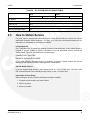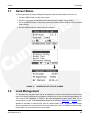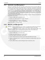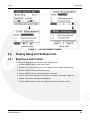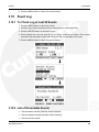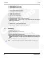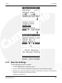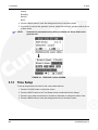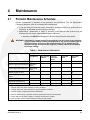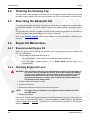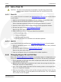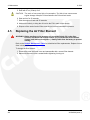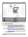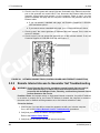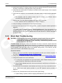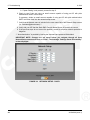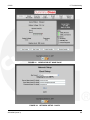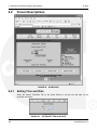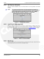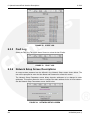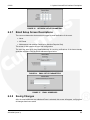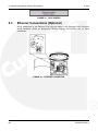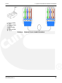
1
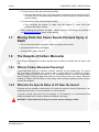
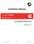
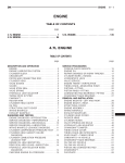
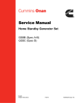
Operator Manual
Home Standby Generator Set
GSBB (Spec A)
English
Original Instructions
9-2010
A029V089 (Issue 3)
Table of Contents
1. IMPORTANT SAFETY INSTRUCTIONS ......................................................................................
1
1.1 Save These Instructions ........................................................................................................
1
1.2 General Precautions ..............................................................................................................
1
1.3 Generator Voltage is Deadly .................................................................................................
1
1.4 Engine Exhaust is Deadly ......................................................................................................
2
1.5 Fuel is Flammable and Explosive ..........................................................................................
2
1.6 Batteries Can Explode ............................................................................................................
2
1.7 Moving Parts Can Cause Severe Personal Injury or Death ..................................................
3
1.8 The Hazards of Carbon Monoxide..........................................................................................
3
2. INTRODUCTION............................................................................................................................
5
2.1 About this Manual ...................................................................................................................
5
2.2 About the Generator Set.........................................................................................................
5
2.3 How to Obtain Service ...........................................................................................................
9
3. OPERATION ...............................................................................................................................
11
3.1 3 Position Switch ..................................................................................................................
11
3.2 In-Home Operator Panel ......................................................................................................
12
3.3 Typical Operation..................................................................................................................
13
3.4 To Enable/Disable Standby .................................................................................................
18
3.5 To Manually Start/Stop Generator Set ................................................................................
18
3.6 Fault, Maintenance and New Event Screens .......................................................................
19
3.7 Genset Status ......................................................................................................................
21
3.8 Load Management ................................................................................................................
21
3.9 Display Setup and Software Info ..........................................................................................
23
3.10 Event Log............................................................................................................................
25
3.11 Fault Log .............................................................................................................................
26
3.12 Exercise Settings ...............................................................................................................
27
3.13 Time Setup ........................................................................................................................
28
4. MAINTENANCE ..........................................................................................................................
31
4.1 Periodic Maintenance Schedule ..........................................................................................
31
4.2 Cleaning the Housing Top ...................................................................................................
32
4.3 Exercising the Generator Set ..............................................................................................
32
4.4 Engine Oil Maintenance........................................................................................................
32
A029V089 (Issue 3)
i
Table of Contents
9-2010
4.5 Replacing the Air Filter Element ..........................................................................................
34
4.6 Battery Maintenance ............................................................................................................
35
4.7 Spark Plugs .........................................................................................................................
36
4.8 Maintenance Record ............................................................................................................
36
5. TROUBLESHOOTING ................................................................................................................
39
5.1 Troubleshooting With the In-Home Operator Panel ............................................................
39
5.2 Fault Code Blinking ..............................................................................................................
39
5.3 Restoring Fault Code Blinking .............................................................................................
39
5.4 Troubleshooting with the Flashing Indicator Light ...............................................................
40
5.5 Communication Troubleshooting ..........................................................................................
45
6. OPTIONAL INTERNET/EMAIL INTERFACE DESCRIPTIONS ...................................................
51
6.1 Introduction ..........................................................................................................................
51
6.2 Screen Descriptions .............................................................................................................
52
6.3 Ethernet Connections (Optional) .........................................................................................
56
ii
A029V089 (Issue 3)
1
IMPORTANT SAFETY INSTRUCTIONS
1.1
Save These Instructions
This manual contains important instructions for the generator set that should be followed during
the operation and maintenance of the generator and batteries.
Thoroughly read this manual before operating the generator set. Safe operation and top
performance can only be obtained when equipment is properly operated and maintained.
The following symbols in this manual alert you to potential hazards to the operator, service
person and equipment.
DANGER: Alerts you to an immediate hazard that will result in severe personal
injury or death.
WARNING: Alerts you to a hazard or unsafe practice that can result in severe personal
injury or death.
CAUTION: Alerts you to a hazard or unsafe practice that can result in personal injury or
equipment damage.
1.2
General Precautions
· Keep ABC fire extinguishers handy.
· Make sure all fasteners are secure and torqued properly.
· Keep the generator set and its compartment clean. Do not store any items in the genset
compartment.
· Excess oil, oily rags (etc.) can catch fire.
· Dirt and gear stowed in the compartment will restrict cooling air flow.
· Before working on the generator set, move the Stop Switch (S2) to the Stop position,
disconnect the remote harness (P7) to disable the ATS mounted charger and then remove
the negative (-) battery cable to prevent starting.
· Use caution when making adjustments while the generator set is running, hot, moving or
when parts are electrically live, as all situations may cause personal injury or death.
· Used engine oil has been identified by some state and federal agencies as causing cancer
or reproductive toxicity. Do not ingest, inhale or come into contact with used oil or it's
vapors.
· Do not work on the generator set when mentally or physically fatigued or after consuming
alcohol or drugs.
1.3
Generator Voltage is Deadly
· Generator output connections must be made by a trained and experienced electrician in
accordance with all applicable codes.
A029V089 (Issue 3)
1
1. IMPORTANT SAFETY INSTRUCTIONS
9-2010
· This standby generator set and the public utility may only be connected to the house
circuits by means of the automatic transfer switch.
· Improper connections can lead to electrocution of utility workers and damage to
equipment.
· Use caution when working on live electrical equipment. Remove jewelry, make sure
clothing and shoes are dry and stand on a dry wooden platform.
1.4
Engine Exhaust is Deadly
· See What Is Carbon Monoxide Poisoning? to learn the symptoms of Carbon Monoxide
poisoning.
· This generator set is for outdoor installation only.
· It must be located well away from doors, windows, other openings into the house and
where the exhaust gases will disperse away from the house.
1.5
Fuel is Flammable and Explosive
· Keep flames, cigarettes, sparks, pilot lights, electrical arc-producing equipment, switches
and all other sources of ignition well away from areas where fuel fumes are present and
areas sharing ventilation.
· Fuel lines must be secured, free of leaks and separated or shielded from electrical wiring.
· Leaks can lead to explosive accumulations of gas. Prevent leaks and the accumulation of
gas.
· A "rotten egg" smell indicates a possible Natural Gas or Propane leak:
· Natural Gas rises when released and can accumulate under hoods and inside
housings and buildings.
· Propane sinks when released and can accumulate inside housings and
basements and other below-grade spaces.
1.6
Batteries Can Explode
Batteries can explode, causing severe skin and eye burns and can release toxic electrolytes.
· Wear safety glasses.
· Do not smoke.
· Do not dispose of the battery in a fire.
· The battery is capable of exploding.
· Do not open or mutilate the battery.
· Released electrolytes have been known to be harmful to the skin and eyes and to be
toxic.
· Batteries present the risk to high short circuit current:
· Remove watches, rings or other metal objects and use tools with insulated handles.
2
A029V089 (Issue 3)
9-2010
1. IMPORTANT SAFETY INSTRUCTIONS
· To prevent arcing when disconnecting the battery:
· Move the Stop Switch (S2) to the Stop position, disconnect the remote harness (P7)
to disable the ATS mounted charger and then remove the negative (-) battery cable to
prevent starting.
· To prevent arcing when reconnecting the battery:
· First, reconnect the positive (+) cable, then the negative (-) cable, and finally
reconnect the battery charger.
· When replacing the generator set battery, always replace it with a battery as specified in
the Model Specifications section of this manual.
1.7
Moving Parts Can Cause Severe Personal Injury or
Death
· Do not wear loose clothing or jewelry near moving parts such as fans.
· Keep hands away from moving parts.
· Keep guards in place, over fans.
1.8
The Hazards of Carbon Monoxide
Engine-driven generators can produce harmful levels of carbon monoxide that can injure or kill
you.
1.8.1
What Is Carbon Monoxide Poisoning?
Carbon Monoxide (CO) is an odorless, colorless, tasteless and non-irritating gas. You cannot
see it or smell it. Red blood cells, however, have a greater affinity for CO than for Oxygen.
Therefore, exposure even to low levels of CO for a prolonged period can lead to asphyxiation
(lack of Oxygen) resulting in death. Mild effects of CO poisoning include eye irritation, dizziness,
headaches, fatigue and the inability to think clearly. More extreme symptoms include vomiting,
seizures and collapse.
1.8.2
What Are the Special Risks of CO Near the Home?
Residents can be exposed to lethal levels of CO when the genset is running. Depending on air
temperature and wind, CO can accumulate in or near the home.
To protect yourself and others from the dangers of CO poisoning, it is recommended that
reliable and approved CO detector alarms be installed in the home.
WARNING: Carbon Monoxide (CO) gas can cause nausea, fainting or death.
A029V089 (Issue 3)
3
1. IMPORTANT SAFETY INSTRUCTIONS
1.8.3
9-2010
Only You Can Protect Yourself From CO Poisoning!
· Locate the generator in an area where there are no windows, doors or other access points
into the home.
· Make sure all CO detectors are working properly.
· Pay attention to the signs of CO poisoning.
· Check the exhaust system for corrosion, obstruction and leaks each time you start the
generator set and every eight hours if you run it continuously.
4
A029V089 (Issue 3)
2
Introduction
Important note for Brazil applications: The manufacturer warns that the installation, operation
and maintenance of equipment by the user must fully comply with the Manual's guidelines and
current Brazilian laws, including those of the Brazilian Agency of Petroleum, Natural Gas and
Fuels (ANP) and the Brazilian Energy Agency (ANEEL).
2.1
About this Manual
This is the Operator Manual for the Model GSBB generator set. Each operator of this generator
set should become thoroughly familiar with the information in this manual and observe all of it's
instructions and precautions.
Refer to the Operation chapter of this manual for instructions and guidelines for operating and
monitoring the genset.
Refer to the Maintenance chapter of this manual for instructions and guidelines for performing
periodic maintenance. The operator is responsible for generator set maintenance in accordance
with the Periodic Maintenance Schedule.
Refer to the Troubleshooting chapter for steps to be taken to diagnose and correct situations
that cause a generator set to shutdown.
WARNING: This generator set is not for life support. It can stop without warning.
Children, persons with physical or mental limitations, and pets could suffer
personal injury or death. A personal attendant, redundant power or an alarm
system must be used if power system operation is critical.
2.2
About the Generator Set
The model GSBB generator set is an engine-powered generator set fueled by Natural Gas or
Propane.
See the Specifications section of this manual for specific information about the generator set.
The generator set is intended as a back-up to utility power. Whenever utility power is
interrupted, the house electrical loads are automatically switched by the transfer switch from the
utility (normal power source) to the generator set (emergency power source). When utility power
is restored, the loads are automatically switched back to the utility. To do this, the generator set
and transfer switch perform the following functions together:
1. Senses an interruption of utility power.
2. Starts the generator set.
3. Transfers the load to the generator set when operation has stabilized.
4. Senses the return of utility power.
5. Retransfers the load to the utility.
6. Stops the generator set.
A more in-depth illustration of the operation of the generator set and transfer switch can be
found in the Timing Charts, located in the Typical Operation chapter of this manual.
A029V089 (Issue 3)
5
2. Introduction
2.2.1
9-2010
Generator Set Nameplate
WARNING: Improper service or replacement of parts can lead to severe personal injury
or death and to damage to equipment and property. Service personnel must
be qualified to perform electrical and mechanical service.
CAUTION: Unauthorized modifications or replacement of fuel, exhaust, air intake or speed
control system components that affect engine emissions are prohibited by law in
the State of California.
Model, Spec and Serial Numbers: Be ready to provide the model, spec and serial numbers on
the generator set nameplate when contacting Cummins Onan for information, parts and service.
Record these numbers so that they are easy to find when needed. Each character in these
numbers is significant for obtaining the right parts listed in the Parts Catalog. Genuine Cummins
Onan replacement parts are recommended for best results.
My Generator Set Information
Model
Spec
Serial Number
FIGURE 1.
2.2.2
NAMEPLATE
Model Specifications
Model GSBB consists of four different variations. These variations are defined in the GSBB
Model Variations table below.
6
A029V089 (Issue 3)
9-2010
2. Introduction
TABLE 1.
GSBB MODEL VARIATIONS
Product
Description
20GSBB-6713A
60 Hz Warm
20GSBB-6714A
60 Hz Cold *
14GSBB-6716A
50 Hz (AU/NZ)
20GSBB-6717A
60 Hz CSA Cold *
* Includes an alternator dryer and engine heater.
NOTE:
See the Cold Weather Specifications Table for recommendations.
TABLE 2.
COLD WEATHER SPECIFICATIONS TABLE
60 Hz
50 Hz
Propane Vapor
Natural Gas
Propane Vapor
Natural Gas
Operating Temperature Range
Above 32 °F (0 °C) and low
humidity
No dryers or starting aids required.
Below 32 °F (0 °C) or high
humidity
Alternator drying heater recommended.
Below 20 °F (-7 °C)
Additional oil heater recommended for starting. Factory-installed model available.
Below 0 °F (-18 °C)
Additional accessory breather heater required to avoid possible engine damage.
See warranty statement.
Below -10 °F (-23 °C)
Additional accessory battery blanket recommended for starting.
Below -20 °F (-29 °C)
Not warranted. See warranty statement.
TABLE 3.
GENERATOR SET SPECIFICATIONS TABLE
60 Hz
50 Hz
Propane Vapor
Natural Gas
Propane Vapor
Natural Gas
Dimensions
Weight (With Oil)
540 lbs (245 kg)
Size (L x W x H)
48 x 43 x 34.6 in (1219 x 864 x 880 mm)
Noise
62 dB(A) at 23 ft (7 m) at normal load. (Normal load is equal to the typical
household consumption of 3 KW.)
TABLE 4.
FUEL SPECIFICATIONS TABLE
60 Hz
50 Hz
Propane Vapor
Natural Gas
Propane Vapor
Natural Gas
132,500 Btu/Hr
35 ft3/Hr
135,000 Btu/Hr
135 ft3/Hr
122,000 Btu/Hr
48 ft3/Hr
114,000 Btu/Hr
110 ft3/Hr
Fueling
1/2 Load
A029V089 (Issue 3)
7
2. Introduction
9-2010
Full Load
275,000 Btu/Hr
110 ft3/Hr
240,000 Btu/Hr
240 ft3/Hr
229,000 Btu/Hr
90 ft3/Hr
213,000 Btu/Hr
205 ft3/Hr
Fuel Pressure
7-11 inches WC
5-11 inches WC
7-11 inches WC
5-11 inches WC
Tank Size
Contact your local gas company to verify the tank size required for your application.
TABLE 5.
ENGINE SPECIFICATIONS TABLE
60 Hz
50 Hz
Propane Vapor
Natural Gas
Propane Vapor
Natural Gas
Engine
2 Cylinder-V Twin, OHV, Air-Cooled, 4-Stroke, Spark Ignited, 3600 RPM
Displacement
60.59 in3 (993 cc)
Spark Plug Gap
.020 inch (.51 mm)
Spark Plug Torque
15 ft-lb (20 N-m)
Intake and Exhaust Cold Valve
Lash
(Measure at 0.25" (6.35mm)
past top dead center)
0.004-0.006 inch (0.10 - 0.15 mm)
Oil Capacity
Approximately 80 oz (2.3 Liters)
Oil Recommendation
(See Operator Manual)
0W-40 Synthetic Engine Oil
TABLE 6.
GENERATOR SPECIFICATIONS TABLE
60 Hz
50 Hz
Propane Vapor
Natural Gas
Propane Vapor
Natural Gas
Generator
Brush-Type, 2-Pole Rotating Field, Single Bearing
Power (kVA)
---
---
13.5
13.5
Rated Voltage (V)
120/240
120/240
115/230
115/230
Rated Current (Amps)
162.6/81.3
143.6/71.8
117.4/58.7
117.4/58.7
Phase Type
Single Phase
Circuit Breaker (Amps)
100
100
60
60
De-rating Guidelines: Maximum wattage or maximum current are subject to and limited by such factors as fuel Btu
content, ambient temperature, altitude, engine power and condition, etc. Full rated power is available at 60 °F (15.5
°C) at sea level. De-rate 3.5% for each 1000 ft (304.8 m) above sea level and 3% for each 10 °F (5.5 °C) increase in
ambient temperature above 60 °F (15.5 °C).This generator is rated in accordance with UL 2200 (Stationary Engine
Generator Assemblies) or CSA C22.2 No. 100-04 (Motors and Generators). The maximum continuous current values
that are listed on the generator set nameplate and specification tables occur at the lower limit of acceptable voltage.
Maximum current occurs at 108 and 216 volts, 10% below nominal voltage 120/240. The voltage set point of this
generator set can be adjusted from the operator panel if desired. Refer to the Operator manual procedure To Adjust
the Output Voltage.
TABLE 7.
CONTROL SPECIFICATIONS TABLE
60 Hz
Propane Vapor
Controller
8
50 Hz
Natural Gas
Propane Vapor
Natural Gas
Integrated Microprocessor-Based Engine, Generator, Transfer Switch Controller
A029V089 (Issue 3)
9-2010
2. Introduction
TABLE 8.
DC SYSTEM SPECIFICATIONS TABLE
60 Hz
Propane Vapor
50 Hz
Natural Gas
Propane Vapor
Natural Gas
DC System
Nominal Battery Voltage
12 Volts DC
Battery Group
26 R
Battery Type
Maintenance Free
Minimum Cold Crank Amps
545
2.3
How to Obtain Service
For parts, service, and product information (such as the Service Manual), contact the nearest
authorized Cummins Onan distributor. You may go to Web site www.cumminsonan.com for
information on contacting our distributors worldwide.
In North America
Call 1-800-888-6626 to contact the nearest Cummins Onan distributor in the United States or
Canada. If you are unable to contact a distributor using the automated service, consult the
Yellow Pages. Typically, our distributors are listed under:
GENERATORS - ELECTRIC
ENGINES - GASOLINE OR DIESEL
If you have difficulty arranging service or resolving a problem, please contact the Service
Manager at the nearest Cummins Onan distributor for assistance.
Outside North America
If you are outside North America, call Cummins Onan at 1-763-574-5000 from 7:30 AM to 4:00
PM, Central Standard Time, Monday through Friday, or fax 1-763-528-7229.
Information to Have Ready
Before calling for service, have the following information available:
1. Complete model number and serial number
2. Date of purchase
3. Nature of problem
A029V089 (Issue 3)
9
2. Introduction
9-2010
This page is intentionally blank.
10
A029V089 (Issue 3)
3
Operation
3.1
3 Position Switch
A three-position Start/Stop switch is located at the genset control panel.
Switch positions available:
· Manual Start: Normally only the maintenance/service technician has occasion to manually
start and stop the generator set. Push the switch down at the thick end to start the set
immediately.
· Stop (middle position): This switch disables the set.
· Remote: For automatic operation, the Start/Stop switch must be in the Remote position
and Standby On must be activated on the In-Home Display. Push the switch down at the
thin end to put into the Remote position.
No.
Description
No.
1
Manual Start Position
3
Stop Position
FIGURE 2.
A029V089 (Issue 3)
2
Description
Remote Position
3 POSITION SWITCH (STOP SWITCH)
11
3. Operation
3.2
9-2010
In-Home Operator Panel
The operator panel must be hard-wired to the generator set in order for the generator system to
operate.
NOTE:
The in-home operator panel and Internet/Email interface can be used
simultaneously
The operator panel consists of two UTILITY status lamps, three GENERATOR status lamps,
three action buttons and an LCD display screen with four navigation buttons.
No.
Description
1
Back Button - When navigating through the LCD menus, press this button to return to the main operating
screen.
2
Standby On/Off Button - See the To Enable/Disable Standby section of this manual.
3
Start Stop Button - See the To Manually Start/Stop Generator Set section of this manual.
4
Navigation Buttons - The function of these buttons change as different screens appear.
FIGURE 3.
3.2.1
IN-HOME OPERATOR PANEL
BACK Button
When navigating through the LCD menus, press the BACK button to return to the main
operating screen.
3.2.2
START STOP Button
See To Manually Start/Stop Generator Set.
3.2.3
Standby ON/OFF Button
See To Enable/Disable Standby.
12
A029V089 (Issue 3)
9-2010
3.3
3. Operation
Typical Operation
NOTE:
The following diagrams are based on an APPROXIMATE time duration. Your
genset may vary slightly from the timing diagrams in this manual.
FIGURE 4.
A029V089 (Issue 3)
TYPICAL POWER OUTAGE CYCLE TIMING DIAGRAM
13
3. Operation
9-2010
FIGURE 5.
14
EXERCISE TIMING DIAGRAM
A029V089 (Issue 3)
9-2010
3. Operation
FIGURE 6.
A029V089 (Issue 3)
MANUAL START/STOP TIMING DIAGRAM
15
3. Operation
9-2010
FIGURE 7.
3.3.1
LOAD MANAGEMENT TIMING DIAGRAM
Normal Operation: Utility Power Available and Connected
As long as utility power is available and connected, both of the green UTILITY lamps
(PRESENT and CONNECTED) will stay on and the LCD screen will indicate “Genset Stopped".
If the red GENERATOR STANDBY OFF light is on, the generator set will not start up
automatically if utility power is interrupted. See the To Enable/Disable Standby section of this
manual to enable STANDBY so that the generator set will automatically supply power if utility
power is interrupted.
16
A029V089 (Issue 3)
9-2010
3. Operation
FIGURE 8.
3.3.2
UTILITY PRESENT AND CONNECTED—STANDBY OFF LAMP ON
Emergency Operation: Utility Power Interrupted
If utility power is interrupted,
1. The green UTILITY PRESENT lamp will go out
2. The generator set will start automatically and the green GENERATOR RUNNING lamp will
turn on.
3. The UTILITY CONNECTED light will go out when the generator set is connected to supply
power.
The LCD screen will provide a visual indication of “Genset Load" (bar graphs). The bar graphs
indicate how much of the available power is being used in each supply line (L1 and L2).
If the red ACTION REQUIRED light comes on, either the generator shut down or periodic
maintenance has come due. The LCD screen will indicate what maintenance is due or which
fault occurred.
FIGURE 9.
A029V089 (Issue 3)
GENERATOR SET RUNNING—ACTION REQUIRED LAMP ON
17
3. Operation
3.3.3
9-2010
To Adjust the Output Voltage
Use the following procedure:
1. Connect an accurate AC volt meter across L1 and L2 while the generator set is running.
2. With Output Volts selected on the Adjustments Menu screen, press the up or down arrow
button to adjust the voltage to the desired setting
3. The control allows an adjustment of 240 VAC ± 7% (17 VAC).
4. Press the BACK button to save the settings and return to the home screen.
3.4
To Enable/Disable Standby
Normally, you should not have to disable generator set STANDBY.
· STANDBY should always be enabled (ON) except during maintenance/service.
· STANDBY will have to be re-enabled (STANDBY OFF light on) if the generator set is
started or stopped manually (normally a maintenance/service function) or a fault shutdown
has occurred.
CAUTION: When STANDBY is disabled the generator set will NOT automatically start to
supply power if utility power is interrupted.
To enable or disable generator set standby:
1. Press the STANDBY ON/OFF button on the operator panel, which takes you to the
Standby ON/OFF screen.
2. Press the up or down arrow button to select ON or OFF.
3. To enable STANDBY select ON and press the BACK button. The STANDBY OFF lamp
will go out and the display will state: “Standby ready enabled by user."
4. To disable STANDBY select OFF and press the BACK button. The STANDBY OFF lamp
will come on and the display will state: “Standby ready disabled by user."
FIGURE 10.
3.5
ENABLE/DISABLE STANDBY SCREEN
To Manually Start/Stop Generator Set
Normally, only the maintenance/service technician has to manually start and stop the generator
set.
· Starting the generator set will result in the generator powering the house loads.
18
A029V089 (Issue 3)
9-2010
3. Operation
CAUTION: Manually starting or stopping the generator set disables generator set STANDBY.
The generator set will not automatically start to supply power if utility power is
interrupted.
Manually start and stop the generator set once every 3 months to test that these
functions are working properly.
To manually start or stop the generator set:
1. Press the START STOP button on the operator panel, which takes you to the Genset
START/STOP screen.
· The screen will display “Genset Stopped" or “Genset Running," as appropriate.
2. Press START to manually start the generator set and connect it to supply power to the
house. The STANDBY OFF lamp will come on and the display will state: “Genset started
manually (Standby Ready Disabled)."
3. Press STOP to manually stop the generator set and disconnect it. The STANDBY OFF
lamp will come on and the display will state: “Genset stopped manually (Standby Ready
Disabled)."
NOTE:
To start the generator set without connecting loads pick Exercise Now on the
Exerciser Clock screen.
FIGURE 11.
3.6
GENSET START/STOP SCREEN
Fault, Maintenance and New Event Screens
Various warning and event screens may appear on the operator panel during Normal or
Emergency Operation.
3.6.1
Fault Screen
If a generator set shutdown fault occurs, a FAULT warning appears with the following
information:
· Brief description of the warning or fault
· The two-digit Fault Code Number
· The time of occurrence of the fault
Press the BACK button to reset the fault and return to the home screen.
See the Fault Log section of this manual to review the log of the last 5 faults.
A029V089 (Issue 3)
19
3. Operation
9-2010
FIGURE 12.
3.6.2
TYPICAL FAULT SCREEN
Maintenance Due Screen
A Maintenance Due screen appears when a scheduled maintenance operation is due.
· The warning does not time out.
· Perform the maintenance.
Press the BACK button to return to the home screen.
FIGURE 13.
3.6.3
TYPICAL MAINTENANCE DUE SCREEN
New Event Screen
A New Event screen appears whenever system status changes, such as when there is an
interruption of utility power. The screen provides a brief description of the event along with the
time and date of the event.
· The message does not time out, unless superseded by a new event.
· Press the BACK button to return to the home screen.
See the Event Log section of this manual to review the log of the last 20 events.
FIGURE 14.
20
TYPICAL NEW EVENT SCREEN
A029V089 (Issue 3)
9-2010
3.7
3. Operation
Genset Status
To check generator set output voltage and frequency and the total numbers of hours run:
1. Press the MENU button on the home screen.
2. Press the up or down arrow button on the menu screen to select Genset Status.
3. Press the ENTER button on the menu screen and note the values displayed on the Genset
Status screen.
4. Press the BACK button to return to the home screen.
FIGURE 15.
3.8
GENERATOR SET STATUS SCREEN
Load Management
The generator set may have been set up at installation to connect and disconnect certain large
loads, such as air conditioners, to manage the total load so as not to overload the generator set.
This requires the installation of relays to the load management signals which allow for the
disconnection of loads. Load management can be set to operate in automatic or manual mode.
Whether in automatic or manual mode, there is a delayed start. Load 1 is enabled three minutes
after the generator set is connected to the house loads, and Load 2 is enabled six minutes after
the generator set is connected to the house loads.
A029V089 (Issue 3)
21
3. Operation
3.8.1
9-2010
Automatic Load Management
When set to automatic mode, the user takes no action and can only view which loads are
connected. Three minutes after the generator starts, the load that is connected to genset load
L1 is connected. After a delay of three more minutes, the load that is connected to genset load
L2 is connected. If the connection of loads L1 and L2 exceeds 95% of the generator's load
capacity, they are disconnected by the generator. Following another three minute delay, the
control reconnects both loads following the same connection sequence used in the first attempt
(three minutes apart). If generator load capacity is exceeded again, both loads are disconnected
and no further reconnection is tried.
To select automatic load management and view whether the selected loads are connected while
the generator set is running:
1. Press the LOAD button on the home screen.
2. Press the up or down arrow button to select Automatic.
3. Note which loads are connected or disconnected.
4. Press the BACK button to return to the home screen.
Adjust percent load to match the de-rate.
3.8.2
Manual Load Management
CAUTION: To reduce unnecessary loss of service, it is highly recommended that manual load
management be undertaken only by an authorized Cummins Onan dealer.
When set to manual mode, the user is able to view, connect, and disconnect loads. If the
connection of loads L1 and L2 exceeds generator capacity, the AC circuit breaker trips.
To select manual load management when the generator is running:
1. Press the LOAD button on the home screen.
2. Press the up or down arrow button to select Manual.
3. Note which loads are connected or disconnected.
4. Press the double-down arrow button to go the load connect/disconnect screen.
5. Connect or disconnect Load 1 or Load 2 as necessary by pressing either button under
Load 1 or Load 2.
6. Press the BACK button to save the setting and return to the home screen.
22
A029V089 (Issue 3)
9-2010
3. Operation
FIGURE 16.
LOAD MANAGEMENT SCREEN
3.9
Display Setup and Software Info
3.9.1
Brightness and Contrast
To change the Brightness and Contrast of the display screen:
1. Press the MENU button on the home screen.
2. Press the up or down arrow button on the menu screen to select Display Setup.
3. Press the ENTER button on the menu screen.
4. Press the NEXT button to select Brightness or Contrast.
5. Press the increase or decrease arrow button to increase or decrease brightness.
6. Change Contrast the same way as Brightness.
7. Press the BACK button to save the settings and return to the home screen.
A029V089 (Issue 3)
23
3. Operation
9-2010
FIGURE 17.
3.9.2
DISPLAY SETUP AND SOFTWARE INFO SCREENS
Software Info
To check on the generator set and display software:
1. Press the MENU button on the home screen.
2. Press the up or down arrow button on the menu screen to select Display Setup.
3. Press the ENTER button on the menu screen.
4. Press the INFO button on the Display Setup screen and note the values displayed on the
Software Info screen.
24
A029V089 (Issue 3)
9-2010
3. Operation
5. Press the BACK button to return to the home screen.
3.10
Event Log
3.10.1 To Check Log of Last 20 Events
1. Press the MENU button on the home screen.
2. Press the up or down arrow button on the menu screen to select Event Log.
3. Press the ENTER button on the menu screen.
4. Scroll through the event log with the up and down double-arrow buttons. Each screen
provides a brief description of the event along with the time and date of the event.
5. Press the BACK button to return to the home screen.
FIGURE 18.
EVENT LOG SCREEN
3.10.2 List of Recordable Events
· "Genset started manually (Standby Ready Disabled)"
· "Genset stopped manually (Standby Ready Disabled)"
· "Genset exercise started"
A029V089 (Issue 3)
25
3. Operation
9-2010
· "Genset exercise completed"
· "Genset started due to loss of utility"
· "Genset stopped with return of utility"
· "Switch on genset moved to remote position"
· "Switch on genset moved to run position"
· "Switch on genset moved to off position"
· "Standby ready disabled by user"
· "Standby ready enabled by user"
· "Utility lost - not in Standby Ready"
· "Utility returned - not in Standby Ready"
· "Maintenance reminder - Change oil and check valve lash"
· "Maintenance reminder - Change oil & filter, air filter, adjust valve lash, clean and check
battery & engine cooling fins"
· "Genset fault - (Fault description appended)"
· "Genset warning - Transfer Switch Signal Failure"
· "Genset warning - Transfer Switch Failed to Transfer to Utility"
· "Genset warning - Low Battery or Battery Charger Failure"
3.11
Fault Log
To check the log of the last 5 faults:
1. Press the MENU button on the home screen.
2. Press the up or down arrow button on the menu screen to select Fault Log.
3. Press the ENTER button on the menu screen.
4. Scroll through the fault log with the up and down double-arrow buttons. Each screen
provides a brief description of the fault, the fault code number and the time and date of the
fault.
5. Press the BACK button to return to the home screen
NOTE:
26
If there are no faults recorded, the “No Stored Faults" screen will appear.
A029V089 (Issue 3)
9-2010
3. Operation
FIGURE 19.
3.12
FAULT LOG SCREEN
Exercise Settings
To set the generator set exercise schedule:
1. Press the EXCER button on the home screen.
2. Press the NEXT button on the Exerciser Clock screen to select the field to change.
3. Press the up or down arrow button to increase or decrease the frequency of exercise and
the day of the week and time of day for exercise.
Frequency selections are:
A029V089 (Issue 3)
27
3. Operation
9-2010
Weekly
Bimonthly
Monthly
Never
4. Press the BACK button to save the settings and return to the home screen.
5. If you want to exercise the generator set now, select Exercise Now, and press either the up
or down arrow.
NOTE:
Scheduled or prompted exercise does not transfer the house loads to the
generator set.
FIGURE 20.
3.13
EXERCISE CLOCK SCREEN
Time Setup
To set up the generator set clock for the current date and time:
1. Press the CLOCK button on the home screen.
2. Press the NEXT button on the Time Setup screen to select the field to change.
3. Press the up or down arrow button to increase or decrease or change the date or time.
4. Press the BACK button to save the settings and return to the home screen.
28
A029V089 (Issue 3)
9-2010
3. Operation
FIGURE 21.
A029V089 (Issue 3)
TIME SETUP SCREEN
29
3. Operation
9-2010
This page is intentionally blank.
30
A029V089 (Issue 3)
4
Maintenance
4.1
Periodic Maintenance Schedule
Periodic maintenance is essential for top generator set performance. Use the Maintenance
Frequency table as a guide for normal periodic maintenance.
· In hot and dusty environments some maintenance procedures should be performed more
frequently, as indicated by the footnotes in the table.
· Maintenance, replacement or repair of emission control devices and systems may be
performed by any engine repair establishment or individual.
· Warranty work MUST be completed by an authorized Cummins Onan dealer.
WARNING: Accidental or remote starting of the generator set can cause severe personal
injury or death. Before working on the generator set, move the switch (S2) to
the Stop position, disconnect the remote harness (P7) to disable the ATS
mounted charger and remove the negative (-) battery cable from the battery
to prevent starting.
TABLE 9.
Maintenance Task
MAINTENANCE FREQUENCY
Maintenance Frequency
First Startup
Check Engine Oil Level
Daily or Every Yearly or
24 Hours
Every 100
Hours
Every 250
Hours
Every 400
Hours
X2, 5
Change Engine Oil and Oil Filter After first 8
hours
X1
Adjust Engine Valve Clearance
X4
After first 50
hours4
Replace Engine Air Filter
X1
Clean and Check Starting
Battery
X
Replace Spark Plugs and Wires
X3
Clean Engine Cooling Fins
X3
Complete System Test
1.
2.
3.
4.
5.
6.
X6
Perform more often when operating in dusty conditions.
Perform more often when operating in high temperature conditions.
Perform sooner if engine performance deteriorates.
Must be performed by a qualified mechanic (authorized Cummins Onan dealer).
Check daily during power outages, or monthly without power outages.
See automatic transfer switch manual for testing of load transfer.
A029V089 (Issue 3)
31
4. Maintenance
4.2
9-2010
Cleaning the Housing Top
The top surface of the generator set housing can be damaged by pressure washing or solvents
and other cleaning agents. Only use soap and water or an “all citrus degreaser" to clean the top.
4.3
Exercising the Generator Set
Exercising the generator set drives off moisture, re-lubricates the engine and removes oxides
from electrical contacts. The result is better starting, more reliable operation and longer engine
life.
The generator set exerciser is capable of automatically starting the generator set and letting it
run for 20 minutes, once every 28 days, or more often, if desired.
Refer to the Exercise Settings section of this manual for more information on setting up the
exerciser.
4.4
Engine Oil Maintenance
4.4.1
Recommended Engine Oil
Check the oil level prior to starting the generator set to verify that the oil level is between the
FULL and ADD marks.
· The generator set is shipped with engine oil
· Any 40W synthetic oil can be used for normal operating temperatures.
· For cold weather operation (below -10 °F), Mobil1 0W-40 synthetic engine oil is
recommended
4.4.2
Checking Engine Oil Level
WARNING: State and federal agencies have determined that contact with used engine oil
can cause cancer or reproductive toxicity. Avoid skin contact and breathing
of vapors. Use rubber gloves and wash exposed skin. Accidental or remote
starting of the generator set can cause severe personal injury or death.
Disconnect the negative (-) battery cable and place the control switch in its
OFF position before starting work.
1. Pull out the dip stick and wipe it clean
2. Reinsert the dip stick
3. Remove the dipstick one final time and check the oil level
NOTE:
The engine oil level indicated on the dipstick should be between the FULL
and ADD marks.
4. Reinsert the dipstick
If the engine oil level check shows excessive or insufficient levels of oil (oil level line above the
FULL mark or below the ADD mark), oil must be drained or added. Refer to the following
sections (Drain Oil or Add Oil - as needed) for instructions and guidelines for draining and
adding oil.
32
A029V089 (Issue 3)
9-2010
4.4.3
4. Maintenance
Add or Drain Oil
CAUTION: Too much oil can cause high oil consumption. Too little oil can cause severe
engine damage. Keep the oil level between the FULL and ADD marks on the
dipstick.
4.4.3.1 Drain Oil
If the oil level is found to be excessive (see Checking Engine Oil Level), oil must be drained
from the engine.
1. Attach one end of the drain hose (shipped loose with the genset) to the oil drain valve
2. Place the other end of the drain hose into an appropriate container.
Refer to local/state regulations to determine the appropriate container for used oil.
3. Open the oil drain valve to release oil from the engine into the appropriate container.
4. Re-check the engine oil level (Checking Engine Oil Level)
Based on the results, add or drain oil.
5. When a sufficient amount of oil has been drained from the system:
a. Close the oil drain valve
b. Remove the drain hose
c. Wipe the oil drain valve clean
d. Dispose of the used oil in accordance with local/state regulations.
4.4.3.2 Add Oil
If the oil level is found to be insufficient (see Checking Engine Oil Level), oil must be added.
1. Add the appropriate amount of oil, based on the engine oil level check performed
beforehand.
2. Re-check the engine oil level (see Checking Engine Oil Level).
Based on the results, add or drain oil.
3. Clean up and dispose of any oil in accordance with local/state regulations.
4.4.4
Changing Engine Oil and Oil Filter
Refer to the Periodic Maintenance Schedule for scheduled engine oil changes and to the
control panel for the oil filter part number. Change oil more often in hot and dusty environments.
1. Run the generator set until warm, shut down and place pan under the end of the oil drain
hose attached to the drain valve.
2. Make sure the oil drain hose is connected to the oil drain valve and open the drain valve.
Reclose the valve when oil stops draining.
3. Spin off the oil filter canister and clean the filter mounting surface on the engine block.
Remove the old gasket if it remains.
4. Make sure the gasket is in place on the new filter and apply a thin film of clean oil to the
gasket. Spin the new filter on until the gasket just touches the block. Turn it an additional
1/2 to 3/4 turn. Do not over tighten.
A029V089 (Issue 3)
33
4. Maintenance
9-2010
5. Refill with 67 oz (2 liters) of oil.
CAUTION: Too much oil can cause high oil consumption. Too little oil can cause severe
engine damage. Keep the oil level between the Full and Add marks.
6. Start and run for 30 seconds.
7. Shut the engine off and wait 30 seconds.
8. Add more oil slowly, to bring the oil level to the FULL mark on the dipstick.
9. Dispose of the used oil and oil filter according to local environmental regulations.
4.5
Replacing the Air Filter Element
WARNING: Before working on the generator set, move the Switch (S2) to the Stop
Position, disconnect the remote harness (P7) to disable the ATS mounted
charger, and remove the negative (-) battery cable from the battery to prevent
starting.
Refer to the Periodic Maintenance Table for scheduled air filter replacements. Replace it more
often in dusty environments.
To change the filter element:
1. Remove the outer and inner cover and reassemble with a new air filter element.
2. Make sure the outer cover is seated before tightening its wing nut.
34
A029V089 (Issue 3)
9-2010
No.
4. Maintenance
Description
No.
Description
1
Dipstick
2
Air Filter
3
Oil Filter
4
Oil Drain
5
Battery
6
Circuit Breaker
7
Control Switch
FIGURE 22.
4.6
MAINTENANCE POINTS
Battery Maintenance
WARNING: Arcing at battery terminals or in light switches or other equipment, and
flames or sparks, can ignite battery gas causing severe personal
injury—Ventilate battery area before working on or near battery—Wear safety
glasses—Do not smoke—Switch work light ON or OFF away from
battery—Stop the generator set—Disconnect the negative (-) battery cable
first and reconnect it last.
WARNING: Before working on the generator set, move the Switch (S2) to the Stop
Position, disconnect the remote harness (P7) to disable the ATS mounted
charger, and remove the negative (-) battery cable from the battery to prevent
starting.
Refer to the Periodic Maintenance Table for scheduled battery maintenance, and follow the
battery manufacturer's instructions. Have the battery charger in the transfer switch replaced if
the battery keeps running down.
A029V089 (Issue 3)
35
4. Maintenance
9-2010
Always:
1. Keep the battery case and terminals clean and dry and the terminals tight.
2. Remove battery cables with a battery terminal puller. Torque threaded stud battery
terminals as recommended by the battery manufacturer.
3. Make sure which terminal is positive (+) and which is negative (-) before making battery
connections, always removing the negative (-) cable first and reconnecting it last to reduce
arcing.
NOTE:
4.7
If the battery needs to be replaced, be sure that the replacement battery
specs match those found in the Specifications Table in this manual.
Spark Plugs
WARNING: Before working on the generator set, move the Switch (S2) to the Stop
Position, disconnect the remote harness (P7) to disable the ATS mounted
charger, and remove the negative (-) battery cable from the battery to prevent
starting.
Set the genset control to the Off position before checking the spark plugs.
Refer to the Periodic Maintenance Table for scheduled spark plug replacement.
The genset has two spark plugs: one on each side of the engine. The spark plugs must be in
good condition for proper engine starting and performance. A spark plug that fouls frequently or
has heavy soot deposits indicates the need for engine service.
To prevent cross threading a spark plug, always thread it in by hand until it seats. Torque the
spark plug to 15 lb-ft (20 N-m).
Return the genset control to Auto when finished performing maintenance.
4.8
Maintenance Record
Record all periodic and unscheduled maintenance and service. See the Periodic Maintenance
Schedule for a list of scheduled maintenance frequency.
DATE
36
HOUR
METER
READING
MAINTENANCE OR SERVICE PERFORMED
A029V089 (Issue 3)
9-2010
4. Maintenance
Record the name, address, and phone number of your authorized Cummins Onan service
center.
A029V089 (Issue 3)
37
4. Maintenance
9-2010
This page is intentionally blank.
38
A029V089 (Issue 3)
5
Troubleshooting
By regularly performing the following periodic maintenance and guidelines, you greatly reduce
the chances of a genset shutdown.
· Maintain an appropriate oil level
· Keep battery connections clean and tight
· Do not overload the generator set
· Keep the air inlet and outlet openings clear
5.1
Troubleshooting With the In-Home Operator Panel
If a fault shutdown occurs the ACTION REQUIRED lamp on the in-home Operator Panel will
come on and the LCD screen will display the a description of the Fault, the Fault Number, and
the hour in total generator set running time when the Fault occurred.
The shutdown codes are listed below in numerical order along with step-by-step corrective
actions.
5.2
Fault Code Blinking
At fault shutdown, the status indicator light will repeatedly blink sets of 1, 2, 3 or 4 blinks.
· One blink indicates shutdown due to high engine temperature.
· Two blinks indicate shutdown due to a loss of engine oil pressure.
· Three blinks indicate a service fault. Press Stop once to cause the two-digit, second-level
shutdown code to blink. (Pressing Stop again will stop the blinking.) The two-digit code
consists of 1, 2, 3, 4 or 5 blinks, a brief pause, and then 1 to 9 blinks. The first set of blinks
represents the tens digit and the second set of blinks the units digit of the shutdown code
number.
· Four blinks indicate that cranking time exceeded 35 seconds.
· Fault Code Nos. 1, 2, 3, and 4 are first level faults. Pay close attention to the pause
sequence to avoid interpreting first level faults as second-level Fault Codes Nos. 11, 22, 33
or 44.
· To avoid the possibility of anyone misinterpreting Code Nos. 3 and 4 as Code Nos. 33 and
44, the latter have not been assigned faults.
5.3
Restoring Fault Code Blinking
The fault code stops blinking after five minutes. Press Stop three times within three seconds to
restore fault code blinking.
NOTE:
A029V089 (Issue 3)
The last fault logged will blink even though the condition that caused the
shutdown may have been corrected.
39
5. Troubleshooting
9-2010
WARNING: Some Generator Set service procedures present hazards that can result in
severe personal injury or death. Only trained and experienced service
personnel with knowledge of fuels, electricity, and machinery hazards should
perform Generator Set service.
5.4
Troubleshooting with the Flashing Indicator Light
The status indicator light on the Control Switch inside the generator set flashes the diagnostic
fault code when a fault shutdown occurs. For a single-digit fault code (2 or 4), the light will flash
2 or 4 times and after a short pause will repeat.
For a two-digit fault code the light will flash the tens digit, pause and flash the units digit and
repeat after a longer pause. Fault 36 would be flashed as follows:
flash-flash-flash—pause —flash-flash-flash-flash-flash-flash—long pause —repeat
NOTE:
5.4.1
For fault history, go to the in-home Operator Panel.
No Response - Status Indicator Light Dead
Possible Cause: Low/No battery voltage, poor battery connection, faulty battery, open harness
connection, faulty start/stop switch, faulty LED
Corrective Actions:
1. Try generator set Start Switch if the remote display Start Switch does not respond, and vice
versa
2. Clean and tighten positive (+) and negative (-) battery cable connections at the battery.
3. Recharge or replace battery. Refer to the battery manufacturer's recommendations.
5.4.2
Starting Battery Runs Down
Possible Cause: Marginal battery connections, battery, charging system, excessive cranking
Corrective Actions:
1. Clean and tighten positive (+) and negative (-) battery cable connections at the battery.
2. Recharge or replace battery. Refer to the battery manufacturer's recommendations.
3. Have battery charger serviced by an authorized Cummins Onan dealer.
5.4.3
Starter Engages - Disengages
Possible Cause: Cranking voltage dips below 8 VDC-Battery connections, battery, charging
system, start/stop switches
Corrective Actions:
1. Clean and tighten positive (+) and negative (-) battery cable connections at the battery.
2. Recharge or replace battery. Refer to the battery manufacturer's recommendations.
3. Have the battery charger serviced by an authorized Cummins Onan dealer.
40
A029V089 (Issue 3)
9-2010
5.4.4
5. Troubleshooting
No AC Power - generator set Running, Status LED On
Steady or Flashing Rapidly
Possible Cause: Circuit breakers tripped due to short circuit or overloading.
Corrective Actions:
1. Reduce number of loads.
2. Reset or turn on generator set circuit breaker.
3. Reset or turn on circuit breaker in the distribution panel.
4. Have the circuits from the generator set and distribution panel verified by an authorized
electrician.
5.4.5
Generator Set Cranks But Does Not Start - No Fault Code
Possible Cause: Faulty or incorrect spark plugs.
Corrective Actions:
1. Check and record last fault code.
2. Crank generator set and troubleshoot fault code and reference last fault code recorded
above if necessary.
WARNING: Some Generator Set service procedures present hazards that can result in
severe personal injury or death. Only trained and experienced service
personnel with knowledge of fuels, electricity, and machinery hazards should
perform Generator Set service.
5.4.6
Genset Warning-Transfer Switch Failed to Transfer to
Utility - No Fault Code
Possible Cause: Transfer switch is faulty, or wire is disconnected or broken
Corrective Actions:
1. Have the utility switch-position wire, wire connections, and transfer switch checked by an
authorized electrician.
5.4.7
Low Oil Pressure Fault - Fault Code 2
Possible Cause: Oil Level too low/high, faulty switch, faulty oil pressure relief valve, faulty oil
pump
Corrective Actions:
1. Check oil level: add or drain oil as necessary.
5.4.8
Overcrank - Fault Code 4
Possible Cause: Faulty switch, faulty external start command, fuel supply, air fuel mixture,
exhaust system, wire connections, starter, ignition system
Corrective Actions:
1. Open any closed fuel valves.
2. Secure spark plug leads to spark plugs.
A029V089 (Issue 3)
41
5. Troubleshooting
9-2010
3. Check and service air filter as necessary.
4. Replace spark plugs.
WARNING: Some Generator Set service procedures present hazards that can result in
severe personal injury or death. Only trained and experienced service
personnel with knowledge of fuels, electricity, and machinery hazards should
perform Generator Set service.
5.4.9
Overvoltage - Fault Code 12
Possible Causes: Generator set loads, wire connections, windings
Corrective Actions:
1. Have unit serviced by an authorized Cummins Onan dealer.
5.4.10 Undervoltage - Fault Code 13
Possible Causes: Generator set loads, wire connections, windings
Corrective Actions:
1. Have unit serviced by an authorized Cummins Onan dealer.
5.4.11 Overfrequency - Fault Code 14
Possible Causes: Generator set loads, engine governor function, fuel supply, air fuel mixture,
exhaust system, choke, demand regulator, carburetor, generator windings, wire connections
Corrective Actions:
1. Have unit serviced by an authorized Cummins Onan dealer.
5.4.12 Underfrequency - Fault Code 15
Possible causes: Generator set loads, engine governor function, fuel supply, air fuel mixture,
exhaust system, choke, demand regulator, carburetor, generator windings, ignition, wire
connections
Corrective Actions:
1. Reduce the number of connected loads especially loads that require higher starting current
such as air conditioners.
2. Have unit serviced by an authorized Cummins Onan dealer.
5.4.13 Governor Actuator shutdown - Fault Code 19
Possible causes: Wire connections, governor actuator
Corrective Actions:
1. Have unit serviced by an authorized Cummins Onan dealer.
5.4.14 Governor Actuator Overload - Fault Code 22
Possible causes: Generator set loads, wire connections, fuel supply, air fuel mixture, exhaust
system, governor actuator, ignition system
42
A029V089 (Issue 3)
9-2010
5. Troubleshooting
Corrective Actions:
1. Reduce the number of connected loads especially loads that require higher starting current
such as air conditioners.
2. Check and service air filter as necessary.
3. Have unit serviced by an authorized Cummins Onan dealer.
5.4.15 Voltage Sense Lost - Fault Code 27
Possible Causes: Generator set loads, generator windings, ignition, wire connections
Corrective Actions:
1. Have unit serviced by an authorized Cummins Onan dealer.
WARNING: Some Generator Set service procedures present hazards that can result in
severe personal injury or death. Only trained and experienced service
personnel with knowledge of fuels, electricity, and machinery hazards should
perform Generator Set service.
5.4.16 High Battery Voltage - Fault Code 29
Possible Causes: Incorrect battery configuration, wire damage, faulty charger, control
Corrective Actions:
1. Have battery charger serviced by an authorized Cummins Onan dealer.
5.4.17 Low Cranking Speed Sense - Fault Code 32
Possible Causes: Starter, engine components, air intake system, exhaust system, generator
windings, wire connections, battery, battery connections, oil viscosity
Corrective Actions:
1. Clean and tighten positive (+) and negative (-) battery cable connections at the battery.
2. Recharge or replace battery. Refer to the battery manufacturer's recommendations.
3. Verify engine oil viscosity is correct for the ambient temperature. If not, refill and replace
engine oil with correct viscosity.
4. Have unit serviced by an authorized Cummins Onan dealer.
5.4.18 Control Card Failure - Fault Code 35
Possible Causes: Faulty program
Corrective Actions:
1. Have unit serviced by an authorized Cummins Onan dealer.
5.4.19 Generator Set Stopped Without Fault Condition - Fault
Code 36
Possible Causes: Fuel supply, air fuel mixture, exhaust system, choke demand regulator,
carburetor, generator windings, ignition, wire connections
A029V089 (Issue 3)
43
5. Troubleshooting
9-2010
Diagnosis & Repair:
1. Check the fuel source.
2. Open any closed fuel valves.
3. Secure spark plug leads to spark plugs.
4. Check and service air filter as necessary.
5. Replace spark plugs.
6. Check for mechanical damage.
5.4.20 Invalid Set Configuration - Fault Code 37
Possible Causes: Generator set configuration, control
Diagnosis & Repair:
1. Have unit serviced by an authorized Cummins Onan dealer.
5.4.21 Processor Fault - Fault Code 43
Possible Causes: Faulty program
Corrective Actions:
1. Have unit serviced by an authorized Cummins Onan dealer.
5.4.22 Speed Sense Fault - Fault Code 45
Possible Causes: Loads, generator windings, wire connections
Corrective Actions:
1. Have unit serviced by an authorized Cummins Onan dealer.
5.4.23 Generator Set Overload - Fault Code 46
Possible causes: Loads, wire connections, windings
Corrective Actions:
1. Reduce the number of connected loads especially loads that require higher starting current
such as air conditioners.
2. Check and service air filter as necessary.
3. Have unit serviced by an authorized Cummins Onan dealer.
5.4.24 Alternator Over Temp - Fault Code 76
Possible Causes: Wire connections, faulty temperature sensor, faulty DC fan, blocked intake or
exhaust openings.
Corrective Actions:
1. Verify the generator set enclosure for clear intake and exhaust openings.
2. Have unit serviced by an authorized Cummins Onan dealer.
44
A029V089 (Issue 3)
9-2010
5. Troubleshooting
5.4.25 Low Fuel Pressure - Fault Code 78
Possible Causes: Wire connections, fuel system, fuel pressure switch
Corrective Actions:
1. Open any closed fuel valves.
2. Have unit serviced by an authorized Cummins Onan dealer.
5.4.26 Failure To Transfer To Generator Set - Fault Code 79
Possible Causes: Wire connections, faulty positional switch, faulty transfer switch component(s).
Diagnosis & Solution:
1. Verify that the main AC circuit breaker on the generator set is to “On".
2. Have unit serviced by an authorized Cummins Onan dealer.
5.5
Communication Troubleshooting
5.5.1
In-Home Network Access to Generator Set
Troubleshooting
WARNING: Some Generator Set service procedures present hazards that can result in
severe personal injury or death. Only trained and experienced service
personnel with knowledge of fuels, electricity, and machinery hazards should
perform Generator Set service.
Possible Causes: Bad connections or bad communications
Corrective Actions:
1. Check connections.
a. Verify that the Ethernet cable is plugged into the generator set control and the router.
b. Verify that the computer is connected to the same router as the generator set via an
Ethernet cable.
c. Verify that the wireless card on the computer is turned off.
d. Check to see if both ends of the Ethernet cable are assembled and crimped as
described in the installation instructions. If not, reassemble and crimp as described in
the installation instructions.
e. Verify that the Ethernet cable connections between the generator set and the router
are solid and correct.
f. Proceed to "Check communications."
2. Check communications.
a. Check to see if you can access a standard web page with the computer connected to
the same router as the generator set. If not, contact your router manufacturer for
troubleshooting information.
A029V089 (Issue 3)
45
5. Troubleshooting
9-2010
b. Check to see if the green and orange lights are illuminated at the Ethernet connection
port on the generator set control board. If not, disconnect the Ethernet cable from the
generator control board and connect it to the computer. Check to see if you can
access a standard web page with the computer connected to the generator side of the
Ethernet cable.
a. If you can access a standard web page, call Cummins Support at 1-800-8886626 and select option 1.
b. If you cannot access a standard web page, go to “Check connections" above.
c. Check to see if the correct generator IP Address has been entered. If not, enter the
correct IP Address.
d. Check to see if you can access the generator set via the in-home network. If not, call
Cummins Support at 1-800-888-6626 and select option 1.
FIGURE 23.
5.5.2
NETWORK CONNECTIONS (CONTROL BOARD AND ETHERNET CONNECTION)
Remote Internet Access to Generator Set Troubleshooting
WARNING: Some Generator Set service procedures present hazards that can result in
severe personal injury or death. Only trained and experienced service
personnel with knowledge of fuels, electricity, and machinery hazards should
perform Generator Set service.
Possible Causes: An improper setup, no high-speed internet connection, the public IP address
is not active or properly set up, an incorrect IP address is entered, the computer is connect to
the same router or network and the generator set, or the internet connection is bad,
Corrective Actions:
1. Check to see if you are able to access the generator set with your in-home computer.
If not, refer to the In-Home Network Access Troubleshooting procedures.
2. Verify that you followed the network setup procedures.
Refer to the Network Setup Guide.
3. Verify that you are using a high-speed internet connection.
46
A029V089 (Issue 3)
9-2010
5. Troubleshooting
4. Verify that the public IP Address is active and set up properly with the ISP (Internet Service
Provider). If necessary, contact the ISP to verify your setup.*
5. Verify that the correct public IP Address is entered into the web browser of the computer
(i.e. xxx.xxx.xxx.xxx).
6. Verify that the computer is not connected to the same router or network as the generator
set.
· The computer used for internet access must be connect to a different internet
connection than the generator set.
7. Check to see if you can access a standard web page from a computer.
· If not, contact the ISP to troubleshoot the internet connection.
8. Verify all settings, as described in the Network Setup Guide.
9. If the previous steps do not correct the problem, contact a computer network specialist to
diagnose.
* To verify your IP Address, access “whatismyipaddress.com" from the browser of a
computer connected to the internet and on the same network as the generator set. This
web page displays your current IP Address which should match the IP Address assigned to
you by your ISP.
5.5.3
Email Alert Troubleshooting
WARNING: Some Generator Set service procedures present hazards that can result in
severe personal injury or death. Only trained and experienced service
personnel with knowledge of fuels, electricity, and machinery hazards should
perform Generator Set service.
Possible Causes: An improper setup, the alert level is not set to “all events," emails cannot be
received, the outgoing email address is not included in your contact list, the email account is not
capable of using port 25 with plain SMTP for the outgoing SMTP server setup, the domain name
is not included in the user name filed of the Network Setup screen, or the DNS #1 and #2
values are incorrect on the Network Setup screen.
Corrective Actions:
1. Check to see if you are able to access the generator set with your in-home computer. If
not, refer to In-Home Computer Access Troubleshooting.
2. Verify that you followed the network setup instructions. Refer to the Network Setup Guide.
3. Verify that the alert level is set to All Events.
a. To verify that your generator set can send emails, select Disable Standby and wait
several minutes to verify that you did receive an email.
b. Select Enable Standby and wait a few more minutes to verify that you did receive a
second email.
4. Send an email to the destination email address and check to see if you received this email.
If not, contact your email service provider or your ISP (Internet service provider) to
diagnose.
5. Check to see if the destination email accounts have spam filtering.
a. If spam filtering is present, add the outgoing email address to your contact list.
A029V089 (Issue 3)
47
5. Troubleshooting
9-2010
b. If spam filtering is not present, proceed to step 6.
6. Check to see if you are using an email account capable of using port 25 with plain
authentication SMTP server setup.
If necessary, obtain an email account capable of using port 25 with plain authentication
SMTP and enter detail into the network setup screen.
7. Verify that the domain name is included in the user name field of the Network Setup screen
(i.e. username@domainname).**
8. Verify with your ISP that the Static DNS (Domain Name Server) #1 and #2 are correct.
9. If the previous steps do not correct the problem, contact a computer network specialist to
diagnose.
** “No authentication" is possible by leaving the username and password fields blank.
IMPORTANT NOTE: Changes are not saved unless you navigate through all three
Network Setup screens and click on “Done". The message “Settings Saved Successfully"
is then displayed.
FIGURE 24.
48
NETWORK SETUP - PAGE 1
A029V089 (Issue 3)
9-2010
5. Troubleshooting
FIGURE 25.
FIGURE 26.
A029V089 (Issue 3)
GENERATOR SET HOME PAGE
NETWORK SETUP - PAGE 2
49
5. Troubleshooting
9-2010
FIGURE 27.
50
NETWORK SETUP - PAGE 3
A029V089 (Issue 3)
6
Optional Internet/Email Interface
Descriptions
6.1
Introduction
This feature allows for in-home or remote access to your generator set through a web page. On
this web page, you can start or stop the generator set, adjust the exerciser day and time,
determine if utility power is available and view the last 20 events/faults on the generator set.
This feature is useful for homeowners who travel or have a second home and want to be able to
remotely interface with their generator set. This feature can also help to reduce troubleshooting
time and service calls when the service technician has access to the same web page.
Use of the Ethernet is not required if you do not use web access. To set up your generator set
for web access, complete installation instructions are included in the Network Setup Guide
instruction sheet, included with your generator set literature package.
The Internet/Email Interface can make the same fault, maintenance and event notices available
to you and to your generator set service contract agency with appropriate Internet Service and
email account.
NOTE:
Technical support for setup and troubleshooting of the hardware used for
in-home network access to the generator set is available through the selling
Cummins Onan dealer/distributor.
The owner may be required to contact their ISP and/or email provider for
technical support of the email notification feature setup and troubleshooting.
Due to the variations in network equipment, network configurations and ISPs,
the owner is responsible for acquiring the needed support/service from a
qualified network specialist to properly and securely set up the owner's
network for remote monitoring of the generator set.
Cummins Onan does not provide technical support for setup and
troubleshooting of the owner's network and email service.
A029V089 (Issue 3)
51
6. Optional Internet/Email Interface Descriptions
6.2
Screen Descriptions
FIGURE 28.
6.2.1
9-2010
HOME PAGE
Setting Time and Date
Select the Genset Time/Date Tab on the Home Screen to set the time and date for the
generator set control.
FIGURE 29.
52
SET GENSET TIME AND DATE
A029V089 (Issue 3)
9-2010
6.2.2
6. Optional Internet/Email Interface Descriptions
Set Exercise Schedule
Select the Exercise Schedule Tab on the Home Screen to set the generator set exercise
schedule.
NOTE:
The generator set will exercise on the first scheduled day for which it is
programmed. After that it exercises on that day at the scheduled interval. For
example, if the generator set is scheduled on a Wednesday for Saturdays
with a monthly interval, the generator set starts on the next available
Saturday. After that it exercises on Saturdays one month apart.
FIGURE 30.
6.2.3
SET EXERCISE SCHEDULE
Load Control (Management)
Select the Load Control Tab on the Home Screen to enable Automatic or Manual Load Control.
In Automatic mode, the user can only view which loads are connected. In Manual mode, the
user can view loads and also connect or disconnect them. See Load Management for details.
FIGURE 31.
6.2.4
GENSET LOAD MANAGEMENT
Event Log
Select the Event Log Tab on the Home Screen to review the last 20 events. See the Event Log
screen capture below for a list of all of the recordable events.
A029V089 (Issue 3)
53
6. Optional Internet/Email Interface Descriptions
9-2010
FIGURE 32.
6.2.5
EVENT LOG
Fault Log
Select the Fault Log Tab on the Home Screen to review the last 5 faults.
FIGURE 33.
6.2.6
FAULT LOG
Network Setup Screen Descriptions
An owner-custom password can be defined in the Network Setup screen shown below. The
user will be prompted to enter the User Name and Password to access this screen.
The Network Setup Parameters screen allows dynamic addresses to be changed to static
addresses. This screen allows the user to configure the static address for the in-home network.
See the Network Setup Parameters screen shown below.
FIGURE 34.
54
NETWORK SETUP SCREEN
A029V089 (Issue 3)
9-2010
6. Optional Internet/Email Interface Descriptions
FIGURE 35.
6.2.7
NETWORK SETUP PARAMETERS
Email Setup Screen Descriptions
The user must determine what events will trigger an email notification of the event:
· Never
· All Events
· Maintenance and Attention Required or Attention Required Only
This screen is also used to set up e-mail configuration.
The user may enter up to three email addresses for receiving notifications of the home-standby
generator set status. See the Email Addresses figure below.
FIGURE 36.
EMAIL SETUP PARAMETERS
FIGURE 37.
6.2.8
EMAIL ADDRESSES
Saving Changes
After the email addresses are added and Done is selected, this screen will appear, verifying that
all changes have been saved.
A029V089 (Issue 3)
55
6. Optional Internet/Email Interface Descriptions
9-2010
FIGURE 38.
6.3
SAVE SCREEN
Ethernet Connections (Optional)
Wiring connections to the Ethernet RJ-45 plug are shown in the Ethernet RJ-45 Connector
Wiring illustration. Utilize an appropriate Ethernet stripping and crimping tool for these
connections.
FIGURE 39.
56
ETHERNET CONNECTOR
A029V089 (Issue 3)
9-2010
6. Optional Internet/Email Interface Descriptions
FIGURE 40.
A029V089 (Issue 3)
ETHERNET RJ-45 CONNECTOR WIRING
57
6. Optional Internet/Email Interface Descriptions
FIGURE 41.
58
9-2010
NETWORK CONNECTIONS
A029V089 (Issue 3)
Cummins Power Generation
1400 73rd Ave. NE
Minneapolis, MN 55432 USA
Phone 1 763 574 5000
Toll-free 1 800 888 6626
Fax 1 763 574 5298
Copyright © 2010 Cummins Power Generation, Inc. All rights reserved.
Cummins, Onan, the "C" logo, and "Performance you rely on." are
trademarks of Cummins Inc.