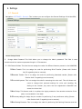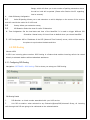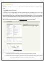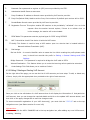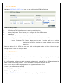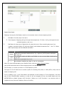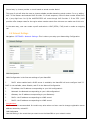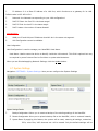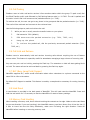
1
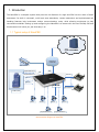
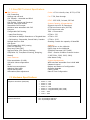
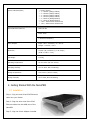
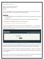
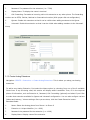
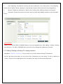
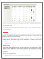
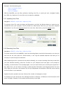
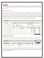
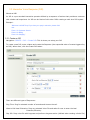
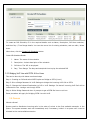
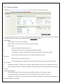
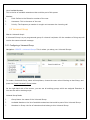
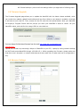
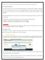
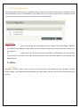
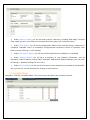
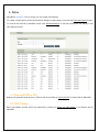
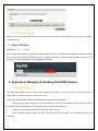
COPYRIGHT 2009-2010 ALLO.COM - VISIT US ONLINE AT WWW.ALLO.COM
1
Table of Contents
1.INTRODUCTION.......................................................................................................................................................................... 4
1.1 TYPICAL SETUP OF NANOPBX.......................................................................................................................................................... 5
1.2 NANOPBX TECHNICAL SPECIFICATIONS............................................................................................................................................ 5
1.3 HARDWARE SPECIFICATIONS.............................................................................................................................................................. 6
2.GETTING STARTED WITH THE NANOPBX......................................................................................................................... 7
2.1 INSTALLATION.................................................................................................................................................................................. 7
2.2 ACCESSING THE GUI (GRAPHICAL USER INTERFACE)......................................................................................................................... 8
3.SETTING UP FEATURES........................................................................................................................................................... 8
3.1 EXTENSIONS..................................................................................................................................................................................... 8
3.1.1 CREATE IP EXTENSIONS
9
3.1.2 CREATE ANALOG EXTENSIONS
10
3.1.3 EDITING / DELETING AN EXISTING IP OR ANALOG EXTENSION
11
3.2 VOICE FILES
12
3.2.1 UPLOADING VOICE FILES
12
3.2.2 RECORDING VOICE FILES
13
3.2.3 KEYPRESS FUNCTIONS
13
3.2.4 MOH (MUSIC ON HOLD)
14
3.3 INTERACTIVE VOICE RESPONSE (IVR)
14
3.3.1 CREATE AN IVR
14
3.3.2 IVR SCHEDULES
16
3.4 QUEUES
17
3.4.1 CONFIGURING A QUEUE
18
3.5 VOICEMAIL GROUP
19
3.5.1 CONFIGURING A VOICEMAIL GROUP
19
3.5.2 ACCESSING, RETRIEVING & MANAGING VOICE MAIL
20
4.SETTINGS
21
4.1 GENERAL....................................................................................................................................................................................... 21
4.2 DID ROUTING............................................................................................................................................................................... 22
4.2.1 CONFIGURING DID ROUTING
22
4.3 VOIP SETTINGS
23
4.4 PSTN LINE.................................................................................................................................................................................. 25
4.5 DIALOUT RULES............................................................................................................................................................................ 25
4.6 NETWORK SETTINGS....................................................................................................................................................................... 27
4.7 SYSTEM SETTINGS.......................................................................................................................................................................... 28
4.8 FIRMWARE UPGRADE...................................................................................................................................................................... 29
4.9 ADVANCE SETTINGS........................................................................................................................................................................ 29
4.9.1 ADVANCE SETTINGS
30
4.9.1.1 STUN SERVER
30
4.9.1.2 NAT TRAVERSAL IP
30
4.9.1.3 RTP RANGE
30
4.9.1.4 ENABLE T.38
30
4.9.1.5 MESSAGE WAIT INDICATION
30
4.9.2 HARDWARE PROFILE
30
4.9.2.1 PHONE PROFILE
30
4.9.2.2 FXS RINGING PROFILE
30
4.9.2.3 LINE PROFILE
30
4.9.2.4 FXO DIALING PROFILE
30
4.9.3 STACKING NANOPBX
31
4.9.4 BLOCK / ALLOW
31
4.10 MANAGE SYSTEM
31
4.11 PORT CONFIGURATION.................................................................................................................................................................. 32
5.STATUS........................................................................................................................................................................................ 32
5.1 STATUS.......................................................................................................................................................................................... 32
5.2 VOICEMAIL STATUS....................................................................................................................................................................... 33
6.STATUS........................................................................................................................................................................................ 34
6.1 DOWNLOAD CDR IN CSV............................................................................................................................................................. 34
6.2 CDR CLEANUP ............................................................................................................................................................................ 34
6.3 CDR CUSTOM SEARCH................................................................................................................................................................... 35
7.APPLY CHANGES...................................................................................................................................................................... 35
8.APPENDIX A: MANAGING & HANDLING NANOPBX FEATURES................................................................................ 35
8.1 ATTENDED TRANSFER..................................................................................................................................................................... 35
8.2 BLIND TRANSFER........................................................................................................................................................................... 36
8.3 3-WAY CONFERENCING.................................................................................................................................................................... 36
8.4 CALL FORWARDING........................................................................................................................................................................ 36
8.5 CALL PARKING.............................................................................................................................................................................. 37
8.6 CALL HOLD AND RETRIEVE............................................................................................................................................................ 37
8.7 BLF (BUSY LAMP FIELD) SUPPORT................................................................................................................................................ 37
8.8 HARD RESET................................................................................................................................................................................. 37
8.9 MEMORY CARD HANDLING............................................................................................................................................................. 37
9.APPENDIX B: PHONES CONFIGURATION REQUIRED FOR NANOPBX INTEROPERABILITY ............................ 38
9.1 X-LITE CONFIGURATIONS............................................................................................................................................................... 38
9.2 SNOM IP PHONE CONFIGURATION................................................................................................................................................ 38
9.3 LINKSYS PAP2 ATA.................................................................................................................................................................... 38
10.APPENDIX C: GLOSSARY OF TERMS................................................................................................................................ 38
1. Introduction
The NanoPBX is a compact system that puts the rich features of a high-end PBX into the reach of small
businesses. Its built-in voicemail, multi-level auto attendants, remote extensions and sophisticated call
handling features help businesses reduce communications costs, while allowing employees to stay
connected worldwide. Setting up and configuring the NanoPBX is a breeze with the user-friendly GUI and
this document will show you just how easy it is!
1.1 Typical setup of NanoPBX
ITSP Provider
Office Local Network
Programmable Line # 4
WAN
LAN
Programmable Line # 3
IP Phone 1
Line # 1
Line # 2
NanoPBX
Upto 50 IP Phones
C O Office / PSTN
Phone 1
Phone 2
Programmable Phone 5
Phone 3
Phone 4
Programmable Phone 6
Interconnection Diagram of NanoPBX
1.2 NanoPBX Technical Specifications
PBX Features:
Call Forwarding
Holding and retrieval
Call Transfer - Attended and Blind
3-way Conference
Call Parking, Pickup and Retrieval
Remote Voice mail Access
Recordable IVR Prompts
Multilevel auto attendant with IVR
Intercom
Configurable Call Routing
Codec: G.711 A-law & μ-law, G.723, G.729
- Least Cost Routing
8 TDM + 3 IP
- Call Route to Multiple Extensions or Targeted User
4 TDM + 8 IP
- Call Hunting - Sequential, Round Robin, Random
Multiple Music on Hold
Call Queue
Direct Inward Dial (DID) routing
Caller ID Spoofing
Busy Lamp Field (BLF)
Regional Caller ID & Country Settings
CDR(Caller ID, Time/Date Incoming, Outgoing,
0 TDM + 20 IP
Stacking: Double the capacity of NanoPBX
Missed)
Voice Features:
2 (RFC 3261, 3262, 3263, 3264)
Host Name Config
Echo cancellation (G.168)
VAD with silence suppression
CNG
Packet loss concealment
Adaptive jitter buffer
Signal discriminator
Attenuation/Gain adjustment
System Management:
WEB interface accessible from LAN & WAN
Password control
Backup and Restore of configuration
Software Upgrade
Factory Reset
Date & Time Configuration
Fax: T.38, Pass-through
DTMF: RFC 2833, In-band, SIP Info
System Capacity & Expandability:
Supports up to 50 IP Extensions
8 TDM concurrent calls (6 G729)
20 IP concurrent calls
TDM + IP scenarios:
Internet:
DHCP server on the LAN side
DHCP client on the WAN side
STUN/NAT traversal (RFC 3489)
SIPv2 - Session Initiation Protocol Version
1.3 Hardware Specifications
Telephone Interfaces (FXS/FXO)
•
•
•
•
•
•
•
•
Network Interfaces
One 10/100Mbps WAN Port
One 10/100Mbps LAN Port
Phone
Phone
Phone
Phone
Phone
Phone
Line 1
Line 2
1
2
3
4
5
6
–
–
– FXS
– FXS
– FXS
– FXS
– Programmable (FXS / FXO)
– Programmable (FXS / FXO)
FXO
FXO
System Indicators(LED)
•
•
•
•
•
•
•
•
•
Internal/External Memory:
RAM: 64 MB
Power (Green)
1 – Phone1 (Orange & Blue)
2 – Phone2 (Orange & Blue)
3 – Phone3 (Orange & Blue)
4 – Phone4 (Orange & Blue)
5 – Phone 5 (Orange & Blue)
6 – Phone 6 (Orange & Blue)
7 & 8 – Reserved for Internal use
1 & 2 – Reserved for Internal use
Flash: 8 Mb
1 GB SD Card Memory
Power Adapter
Input: 100V – 240V AC / 47 ~ 63 Hz
Output: +12V DC / 2.5 A
Dimension
175mm (W) x 253mm (L) x 34 mm(H)
(6.88” x 9.96” x 1.33”)
Unit Weight
0.55 kg
Operating Temperature
10°C to 40°C (50°F to 104°F)
Operating humidity
10% to 90%, Non-condensing
Storage temperature
0°C to 50°C (32°F to 122°F)
Storage humidity
5% to 95%, Non-condensing
2. Getting Started With the NanoPBX
2.1 Installation
Step 1: Plug one end of the RJ45 Ethernet
cable into your Router
Step 2: Plug the other end of the RJ45
Ethernet cable into the WAN port of the
NanoPBX
Step 3: Plug the Power Adapter included
into an available power outlet
Step 4: Plug the other end of the Power
Adapter into the “DC-IN” port of the
NanoPBX
Step 5: The NanoPBX will power up, and automatically connect itself to your network via DHCP (which
you can later configure in the SETTINGS > Network Settings section)
Important Note:
•
Wait until the POWER and all the six PHONE LED's turn orange and remain stable on the Front Panel
of your NanoPBX.
•
Use Straight – through Ethernet cable to connect between the NanoPBX to Router/Switch/PC
Step 6: Configure your NanoPBX according to the instructions below
2.2 Accessing the GUI (Graphical User Interface)
Connect an Analog phone to the any of the FXS ports of the NanoPBX and dial “* *” to get the WAN IP
address of the NanoPBX. And then launch the web browser on the PC which is connected to the same
network to get GUI Login Screen.
Or also you can access the GUI of the NanoPBX by connecting a PC to the LAN port of the NanoPBX.
Enable the DHCP option in the Network Settings of the PC, and then enter http://192.168.113.1 in the
Web Browser Address field. (Where 192.168.113.1 is the default local IP address of the NanoPBX).
On the login screen, the default username and password is “admin/admin”. Press the Login button to
enter the NanoPBX web panel. To change the password, please refer to the SETTINGS > General section
in the navigation.
After you login, you are brought to an Overview screen, which offers information about the NanoPBX,
and help files to assist you in learning about the different features of the system.
Important Note:
Recommended to use Mozilla Firefox or Internet Explorer 6 & above version Web browser.
3. Setting up Features
3.1 Extensions
Extensions are the core of the NanoPBX. An extension is a number mapped to a person. So basically,
every employee that is connected to the NanoPBX should have their own unique extension number, so
that he/she can be reached, and be able to place calls.
The NanoPBX supports 2 types of Extensions: IP Extensions and Analog Extensions.
IP Extensions:
IP extension are devices that have only data networking connection such as Ethernet and they
communicate with the NanoPBX using IP based protocol for signaling and Voice, examples are
IP Phone,
Soft Phone application. The NanoPBX can support up to 50 IP Extensions
registration.
Analog Extensions:
An Analog Extension is used with a regular telephone system which can be connected to an
available FXS port on the back of the NanoPBX. The NanoPBX can have up to 6 Analog
Extensions.
All the features are supported by both the Analog and IP extensions. Extensions can be part of other
features, such as: Queues and Voicemail Groups. Also, the extension can have a voicemail of its own.
3.1.1 Create IP Extensions
Navigation: CREATE > Extensions > Create IP Extensions: This is where you setup your IP extensions
To add a new IP Extension, fill in the required pieces of information, such as Name, Extension #,
Password, Call Forwarding (optional) and select if you like to make that extension available for Queue
and Voicemail configuration. You can also configure various Codecs and can also prioritize the active
Codecs using the up and down arrows.
Once you are done, click the Create Extension button.
Extensions Details
1.
Name : Name of the extension
2.
Extension #: Unique identifier (i.e.: 7788)
3.
Password: The password for the extension (i.e.: 7788)
4.
Display Name: To display the name in terminal
5.
Call Forwarding: Forwards an incoming call to this extension to any other phone. The forwarding
number can be PSTN, Cellular, National or International number (With proper dial out configuration).
6.
Queues: Enable this extension so that it can be visible when adding members to the Queue.
7.
Voicemail: Enable this extension so that it can be visible when adding members to the Voicemail
Group
3.1.2 Create Analog Extensions
Navigation: CREATE > Extensions > Create Analog Extensions: This is where you setup your Analog
extensions
To add a new Analog Extension, first select the Name option by choosing from one of the 6 available
Phone lines. If any are being used, this section will display what is available. Then, fill in the required
pieces of information, such as Extension #, Password, Call Forwarding (optional) and select if you’d like
to make that extension available for Queue and Voicemail configuration. You can also configure various
Codecs and Latency / Volume settings. Once you are done, click the Create Extension button.
Extensions Details
1.
Name: Select the Analog phone from Phone 1 to Phone 6
2.
Extension #: Unique identifier (i.e.: 1006)
3.
Password: the password for the extension (i.e.: 1006)
4.
Display Name: Display name of the extension
5.
Call Forwarding: Forwards an incoming call to this extension to any other phone. The forwarding
number can be PSTN, Cellular, National or International number (With proper dial out configuration).
6.
Queues: Enable this extension so that it can be visible when adding members to the Queue.
7.
Voicemail: Enable this extension so that it can be visible when adding members to the Voicemail
Group
Important Note:
Make sure to click the APPLY CHANGES button in the top navigation bar, after adding / editing / deleting
any Extension. The APPLY CHANGES tab turns red if some changes are made and not saved.
3.1.3 Editing / Deleting an Existing IP or Analog extension
Navigation: CREATE > Extensions. This is where you can edit / delete existing IP Extensions.
On the right side of the page, you can see the list of extensions you have setup. To edit, or delete any
of them, simply click the appropriate icon provided to the right of each account/Extension.
Once you click on the Edit button of an IP Extension then it will display the information of that particular
IP extension. Here you can change the required details and then click on the Update Extension button to
save the changes made.
You can delete an IP extension by clicking on the delete button of the IP extension from the list of
extensions displayed.
Important Note:
1.
The Voicemail PIN password will be same as the password provided to the Extension while creating an
Extension. This will applies to both Analog and IP Extension. If you are trying to access or retrieve Voice
Message, use that particular Extension password.
2.
If you have done any changes like adding, editing or deleting any option on the NanoPBX, APPLY
CHANGES tab in the top navigation bar will turns red, indicates that it is necessary to click on APPLY
CHANGES button for the changes to take effect.
3.2 Voice Files
What are Voice Files?
Voice Files are the pre-recorded audio files. This files can be used for IVR Playback (With or without
Keypress), or which can be used for Music on Hold (the music that a user hears when his call on hold).
These files can be recorded with any audio recording software, through the NanoPBX, or by hiring a
Voice Talent.
Example 1: Voice file without Key press
“Welcome to ACME Corp! If you know your party’s extension, please dial it now.
Example 2: Voice file with Key press
Press 1 for Customer Service
Press 2 for Billing
Press 3 for Shipping”
With the NanoPBX, you can either upload an existing voice file, or record your own. Accepted formats
are: GSM only. Maximum 50 voice files can be created or uploaded.
3.2.1 Uploading Voice Files
Navigation: CREATE > Voice Files > Add Voice Files
To upload a Voice File, enter the Name and Description, and click the Browse button to select the prerecorded file from your computer. The file should be in GSM format. After this, you may enter Keypress
Information if you like (see Keypress section for more info). When done, press the Upload button.
3.2.2 Recording Voice Files
Navigation: CREATE > Voice Files > Add Voice Files
Te record a Voice File from NANOPBX, check the Recording Option, and select the extension you wish you
use from the list, then press the
Record button, it will ring the selected extension and allow you to
record your voice through this extension.
After answering the call a prompt will be played indicating you to start recording with beep sound Once
you have finished recording, press the # button on your telephone and once again it will prompt for
recording, record the same voice message again, once you have finished your recording then press the #
key. When done, you can leave it like that, or add Keypress Information (see Keypress section for more
info). When you are done, click Upload. The file will automatically be saved as a GSM file, and be stored
on the SD Card in your NanoPBX.
Repeat the above operation as many times as the number of messages to record.
For Example you can record the voice message as show in Example 1 of What are voice files section and
store it as Msg1. Example 2 of the same section and store it as Msg2.
Important Note:
The extension which is used for recording should have G.711 u-law codec. To play the uploaded voice file
from NanoPBX Quick Time player is required. The voice files can be recorded from only FXS ports (phone
port) 1 to 4.
3.2.3 Keypress Functions
Keypress options are available to the caller when a Voice File is played back through an IVR. Depending
what your voice File sounds like (see above example2) you can add any number of Keypress Actions by
first selecting a key number, and then the action (Example in the screen shot key press 5 goto
Extension). Then Press the +Add button to continue, then in the keypress action select the extension
number to ring repeat the above to continue adding more Keypress Actions, as you desire.
3.2.4 MOH (music on hold)
This is a music file which will be played by the NanoPBX when any of the calling party is kept on hold.
All the voice files / music files which are added through Add Voice Files option will be listed in the MOH
selection box. Chose any of the Voice/Music file form the drop down box and click on Apply Changes tab
to save the changes made.
3.3 Interactive Voice Response (IVR)
What is an IVR?
An IVR is a pre-recorded interactive operator defined by a sequence of actions that provides a customer
with a better call experience. An IVR can be ‘chained’ with other IVR’s creating a multi-level IVR system.
Example 1:
“Welcome to ACME Corp! If you know your party’s extension, please dial it
now.
Press 1 for Customer Service
Press 2 for Billing
Press 3 for Shipping”
3.3.1 Create an IVR
Navigation: CREATE > IVR > Create IVR: This is where you setup your IVR
To create a new IVR, enter a Name and create the Sequence (the sequential order of events triggered by
an IVR). When done, click the Create IVR button.
There are different types of Sequences:
Ring Time: Ring for selected number of seconds and Answer the call.
Allow to Dial Local Extension: Plays any selected Voice File and waits for user to enter the local
Extension/Directory.
Play IVR: Plays voice file with keypress and performs keypress action (defined when creating a Voice File)
and Loop to how many times the IVR need to playback.
Goto: Transfers the call to an Extension, Queue, Voicemail group, Bridge to PSTN / IP etc.
Hangup: To end the call.
Example of an IVR:
To create an IVR as shown in Example 1
Enter the IVR Name then select the sequences to be followed,
Select step as 1 and type as Ring time and click on Add button
Select ring time as 2 so the incoming call rings for 2 seconds before answering.
Select step as 2 and type as Allow user to dial Local Extensions and click on Add button
Select the voice file as Msg1 which was created in Create Voice file section.
Select step as 3 and type as Play IVR and click on Add button
Select the voice file as Msg2 which was created in Create Voice file section. And select the Loop as 3 so
the IVR file plays for 3 times before taking further action.
Select step as 4 and type as GoTo & click on Add button
Select the option where the call has to go if the user does not press any keys. In the above example the
call will be routed to the extension number 131
Select step as 5 and type as Hangup and click on add button
This completes the IVR. Click on Create IVR and then press APPLY CHANGES tab, to save this IVR.
3.3.2 IVR Schedules
Navigation: CREATE > IVR > Create IVR Schedules: This is where you setup IVR Schedules, or
manage existing ones
What is an IVR Schedule?
An IVR Schedule allows an IVR to be played at a specific time. You can create multiple schedules, and
play different IVR’s based on specific times (i.e.: Morning and Evening schedules).
To create an IVR Schedule, fill in the required details such as Name, Description, IVR Menu selection,
and then Day / Time Range details. You can also see a list of existing schedules, and can edit / delete
them.
When done, click the Create IVR Schedules button.
Create IVR Schedules Details
1. Name: The name of the schedule
2. Description: A short description of the schedule
3. IVR Menu: The IVR to be played.
4. Day / Time Range: The days and start/end time to play the selected IVR
3.3.3 Bridging VoIP Line with PSTN & Vice Versa
This can be done by with below mentioned steps
Step 1: Creating an IVR and select GOTO option as Bridge to PSTN (Line 1)
Step 2: Give a Bridge Password in VoIP Settings to bridge the incoming VoIP Call to PSTN.
Step 3: Change the Inbound Destination to IVR in VoIP Settings. So that all incoming VoIP Call will be
redirected to Line 1 and go out through PSTN.
Step 4: Dial a Bridge Password when it prompts to get a PSTN Dial tone to call out.
Same procedure will apply for Bridging PSTN Line with VoIP
3.4 Queues
What is a Queue?
Queues used to distributes incoming calls in the order of arrival to the first available extension in the
queue. The system answers each call immediately and, if necessary, holds it in a queue until it can be
directed to the next available extension.
This feature is used to balance the workload among group of extensions.
Queues will provide the following functions,
•
Incoming calls being placed in the queue
•
Extensions that answer the call in the queue.
•
A strategy for how to handle the calls in the queue and distribute the calls in the queue.
•
Music played while waiting in the queue.
3.4.1 Configuring a Queue
Navigation: CREATE > Queues > Create Queue: This is where you setup your Queues.
To create a Queue, simply fill in all the required details including Queue Name, Type, Max Queue Length,
and select the other options. When done, click the Create Queue button.
Queue Details
Queue Name: The name of the Queue
1.
2.
Queue Extn: Extension number to reach the Queue directly
3.
Queue Type:
a.
Ring All: Rings all available extensions
b.
Round Robin: Takes turns ringing each available extension
c.
Least Recent: Rings the extension which was least recently called by this queue
d.
Fewest Calls: Rings the extension with fewest complete calls from
this queue
e.
Random: Rings a random extension
f.
Round Robin Memory: Performs a Round Robin remembering where we left off with the
last ring pass
4.
Max Queue Length: The maximum number of callers waiting in queue for an available extension.
5.
Queue Timeout: Select the required seconds so that the queue will get terminated after the given
seconds
Announcement Options
Announcement Hold Time: Announces an estimated hold time to the caller in queue
1.
2.
Announce Frequency: How often a caller is announced of his/her position in queue
3.
Wrap-Up Time: After a call is finished, the time it takes an extension to become available again to
become available in the queue
List of Available Members
This is the list of available extensions that could be part of this queue
Members
1.
Ext#: Refers to the Extension number of the user
2.
Username: This is the name of the user
3.
Priority: The frequency a member is sought out to answer the incoming call
3.5 Voicemail Group
What is a Voicemail Group?
A Voicemail Group is a pre-programmed group of voicemail recipients. All the members of this group will
receive the same voicemail message.
3.5.1 Configuring a Voicemail Group
Navigation: CREATE > Voicemail Group: This is where you setup your Voicemail Groups
To create a Voicemail Group, select a Group Name, choose the users who will belong to that Group, and
press the Create Voicemail Group button.
On the right-hand side of the screen, you can see all existing groups, which are assigned Extension #.
You can also edit or delete groups.
Voicemail Group Details
1.
Group Name: the name of the Voicemail Group
2.
Available Members: the list of available extensions that could be part of this Voicemail Group
3.
Members in Group: the list of extensions that belong to this Voicemail Group
3.5.2 Accessing, Retrieving & Managing Voice Mail
The NanoPBX allows users to manage voicemail through voice messages in their phones. This section will
summarizes how to access, retrieve and manage voicemail and other settings.
The default feature code for accessing Voicemail is 800. After dialing this code, you will enter a basic
voice menu with the option to listen or forward messages and configure voicemail options. When
prompted, provide the appropriate Voice Mail number and the password, which is same as it was
configured in the Create > Extensions i.e. Extension # & Password.
While you listen to the recorded voice message you can use the following keys for navigation.
•
•
1 - New Messages
•
2 - Change folders
•
3 - Advanced options
•
1 - Send reply
•
2 - Call back
•
3 - Envelope
•
4 - Outgoing call
•
5 - Leave message
•
* - Return to main menu
0 - Mailbox options
•
1 - Record your unavailable message
•
2 - Record your busy message
•
3 - Record your name
•
4 - Record your Temporary Greetings
•
Change your password
•
* - Return to the main menu
•
4 - Play previous message
•
5 - Repeat current message
•
6 - Play next message
•
7 - Delete current message
•
8 - Forward message to another mailbox
•
9 - Save message in a folder
•
* - Help; during message playback: Rewind
•
# - Exit;
4. Settings
4.1 General
Navigation: SETTINGS > General: This is where you can configure the General Settings of the NanoPBX.
General Settings Details
1.
Change Admin Password: This field allows you to change the Admin password. This field is case
sensitive and the maximum password length is 25 characters.
2. PBX Feature Prefixes: This lets the user assign the codes for different features present in the NANOPBX.
2.1 Blind Transfer: This is to assign the code for performing Blind Transfer (Please refer Section
No.8.2 regarding how to execute).
2.2 Attended Transfer: This is to assign the code for performing Attended transfer (Please refer
Section No.8.2 regarding how to execute).
2.3 Voice Mail Operator: This is to assign the code for accessing the voice mail. This will allows endusers to change their personal settings for voice mail handling. By
dialing to this number, any users who are registered to NanoPBX can
access the Voice Mail.
2.4 Call Pickup: This feature code is to pickup the ringing extension from another extension if the
party is not available in the desk.
2.5 Three way calling pin: Assign the pin number for performing 3-way conference calling (Please
refer Section No.8.3 regarding how to execute).
2.6 Call Parking Extension: This is to assign the code for performing Call Parking Extension and the
Range, which will allow you to set number of parking extensions where
the call on hold will be parked (Please refer Section No.8.2 regarding
how to execute)
3.
3.1
Caller ID/Country Configuration:
Caller ID Spoofing: Allows you to set extension no which displays on the screen of the receiver
and will override the caller-id of VoIP trunk
3.2
Country: Allows you to select the country.
3.3
CID Detection: Select the tone for caller ID detection
4. Time Configuration: Set the local date and time of the NanoPBX. It is used to trigger different IVR
Schedules. Manual entry of time will set to default when you reboot NanoPBX.
5. NTP Configuration: URI or IP address of the NTP (Network Time Protocol) server, which will be used by
the phone to synchronize the date and time.
4.2 DID Routing
What is a DID?
A DID is an incoming phone number. DID Routing is a feature that enables incoming calls to be routed
directly to selected stations without attendant assistance.
4.2.1 Configuring DID Routing
Navigation: SETTINGS > DID Routing: This is where you setup your DID Routing
DID Routing Details
1.
DID Number: a virtual number associated with your VoIP service
2.
Link DID to station: when selected to any Extension/Queue/IVR/Voicemail Group, all incoming
calls through this DID are going to be redirected to the selected station
4.3 VoIP Settings
Navigation: SETTINGS > VoIP Settings: This is where you setup VoIP Account(s), or manage existing
ones
4.3.1 Adding a New VoIP Account:
In this page, fill in the Account Name, Username, Password and Proxy information given to you by your
VoIP provider (known as SIP Credentials). You will also need to configure the Dial Settings for that
account (allowing you to route
the incoming calls to a particular destination, i.e.: IVR or IVR Schedule).
Apply any Codec Settings required. You can prioritize your active codec’s by using the up and down
buttons.
After you have entered the details, click the Create VoIP Account button at the bottom.
Adding a New VoIP Account Details
1.
Account Name: SIP service subscriber name which will be used for Caller ID display.
2. Username: User account information, provided by VoIP service provider (ITSP), usually has the
form of digit similar to phone number or actually a phone number.
3.
Password: Set a password to register to (SIP) servers provided by the ITSP.
4.
Authorization UserID: Same as username.
5.
Proxy IP Address: IP address or Domain name provided by VoIP service provider.
6. Proxy Port (Default: 5060): Used to set the Proxy Port numbers. By default port number will be 5060.
7.
Domain/Realm: Domain name provided by VoIP service provider.
8. Registration Time-out: This option enables SIP sessions to be periodically "refreshed" via a re-invite
request. Once the session interval expires, if there is no refresh via a reinvite message, the session will be terminated.
9.
DTMF Mode: This parameter sets the payload type for DTMF using RFC2833
10.
NAT: It should be check if the device is behind a NAT router.
11. Qualify: This feature is used to keep a UDP session open to a device that is located behind a
Network Address Translation (NAT).
12.
Dial Settings:
Dial out Prefix – A numeric identifier value to cease the line. While creating the prefix please make
sure, it should not override the prefix in Setting > General Settings and PSTN
Settings
Bridge Password - This password is required to bridge the VoIP calls to PSTN.
Inbound Destination - This feature allows you to route the incoming calls to particular extension.
13.
Codec Settings: This field allows you to enable a Codec's.
4.3.2 Editing / Deleting an Existing VoIP Account:
On the right side of the page, you can see the list of VoIP accounts you have setup. To edit, or delete any
of them, simply click the appropriate icon provided to the right of each account.
Once you click on the edit button of a VoIP account then it will display the information of that particular
VoIP account, here you can change the required details and click on the update VoIP account button and
then click on the apply changes tab to save the changes made.
To ensure successful registration of your VoIP Account(s), you must click the “STATUS” tab on the top
navigation menu (see Status section for more info)
Important Note:
Make sure to click the APPLY CHANGES tab in the top navigation bar, after adding any new VoIP account,
or editing / deleting.
4.4 PSTN Line
Navigation: SETTINGS > PSTN Line: Here you can configure the PSTN Line Settings
PSTN Line Settings Details
1.
PSTN Settings: This field allows you to select the particular line
2.
Latency Configuration: This will allow you to configure the Jitter Buffer values
3.
a.
Dial Settings:
Dial out Prefix: A numeric identifier value to cease the line.
b.
Bridge Password: This password is required to bridge the VoIP / IP calls to PSTN
c. Inbound Destination: This feature allows you to route incoming calls to a particular
destination i.e. IVR or extension or queues available from the drop
down box.
Once the settings for the PSTN line were made click on the update button and then click on the apply
changes button to save the changes made.
4.5 DialOut Rules
What are DialOut Rules?
DialOut Rules represent the prefix sequence used to dial when making an outgoing call either through
PSTN or VoIP.
It is prefix used to configure to enable system to judge outgoing call via FXO or VOIP and also used to
select a Least cost Routing provider. This will allow user to configure add/delete of rule.
There are two ways to make outgoing calls for the registered extension users:
=> VoIP / SIP trunk via ITSP gateway
=> LINE / PSTN trunk via FXO port
4.5.1 Configuring Dial Out
Navigation: SETTINGS > DialOut Rules: This is where you configure DialOut Rules.
DialOut Rules Details
Please go through the Dial Pattern section to know about how to choose outgoing trunks.
1.
Rule Name: Provide proper rule name
2. Trunk Sequence: Outgoing calls go through these sequences. If it fails, it will go through the next
selected sequence, and so on
3.
Dial Pattern: A unique set of digits that will select this trunk. Enter one dial pattern per line.
A pattern consists of digits 0-9, digit set [digits], and wildcard characters like "." and "X". Below
table explains digit set and wildcard characters.
Expression Description
X
Match any single digit listed explicitly. E.g., digit set [13579] match odd digits.
One may use
'-' a
towildcard,
indicate amatch
rangeany
of digits,
Is
digit ine.g.
any[2-8].
length i.e. one or more digits. Usually given
in the end
of a pattern
to include
all numbers
Match
any single
digit from
0 to 9.
|
Is a wildcard, matches any digit i.e. zero or more digits
[digits]
. (dot)
When you have finished adding your DialOut Rules, click the Update Changes button.
Here we will discuss about how to choose outgoing trunks in two different ways.
The First way is, choose a provider or a trunk based on prefix.
This type of rule will allow user to create a prefix for choosing SIP (VoIP) or LINE (PSTN / FXO) trunk to
make an outgoing call.
For e.g. adding '01|X.' in the Dial Pattern and selected a VoIP Provider1 in Trunk Sequence, will allow
user to dial 014567807890 numbers, so that 01 will be stripped off from the dialed digits and only
4567807890 are dialed through VoIP Provider1. (Where as a VoIP Provider1 is an account which is
registered to any Internet Telephony Service Provider)
Second way is, choose provider or trunk based on actual number dialed
This type of rule will allow the user to choose suitable provider based on actual number. For e.g. adding '
44X.' in Dial Pattern and selected VoIP Provider 2 in trunk sequence, PBX will allow number dialed from
44 + (any digit from 0 to 9) like 449872837532 will route through VoIP Provider 2. If the ITSP / VoIP
provider offer cheaper rates for the region where number starts from 44 users can make use of this rule.
In the same way, user can create a prefix and select a LINE (PSTN / FXO) trunk to make an outgoing
call.
4.6 Network Settings
Navigation: SETTINGS > Network Settings: This is where you setup your Networking Configuration
WAN Configuration
WAN Configuration is the Internet settings of your NanoPBX.
1.
DHCP: when enabled and a DHCP server is available, the NanoPBX will auto configure itself. If
DHCP is not available, select Disable, and fill in the Network Configuration
2.
IP Address: the IP address corresponding to your LAN configuration*
3.
Netmask: the Netmask corresponding to your LAN configuration*
4.
Gateway: the IP address corresponding to your Gateway*
5.
DNS 1: the IP address corresponding to a DNS server*
6.
DNS 2: the IP address corresponding to a DNS server*
Important Note:
DHCP mode isn't recommended. Or trouble may arise when end user need to change registration server
address caused by revised IP.
LAN Configuration
Use this setting in the event that you want to use the NanoPBX as your network router.
1.
IP Address: It is a Base IP Address of a LAN Port, which functions as a gateway for its LAN.
Default value is 192.168.113.1*
2.
Netmask: the Netmask corresponding to your LAN configuration*
3.
DHCP IP Start: the first IP in the lease range*
4.
DHCP IP End: the last IP in the lease range*
5.
DHCP Leases: the number of leases allowed*
Important Note:
1.
WAN port IP and LAN port IP Address shouldn't be in the same net segment.
2.
LAN Configuration cannot be editable.
Host Configuration
Host Configuration is used to manage your NanoPBX’s Host Name.
Host Name: Used to name the device to identify inside the LAN network. This field is optional but may
be required by some Internet Service Providers or system administrators.
When you are finished applying Network Settings, click the Update button.
4.7 System Settings
Navigation: SETTINGS > System Settings: Here you can configure the System Settings
System Settings Details
1.
Backup Configuration: Allows you to create a backup of the existing settings of the NanoPBX
2. Restore Configuration: Allow you to upload a backup file to the NanoPBX, which is restored instantly
3. System Reset: By applying this feature, the system will be reset, meaning all settings, extensions,
IVR’s, voice files, VoIP Accounts etc. will be erased. Only the default settings will be
left. Please backup or print out all the settings before you approach to following steps
4.8 Firmware Upgrade
The Firmware Upgrade page allows you to update the NanoPBX with the latest release available, which
can contain key updates, added functionalities and bug fixes. When a new release is available, download
it and save to your local PC. Then, browse for the file, and click the Upload button. Now your NanoPBX
will display a Progress Screen and will prompt you when your NanoPBX is about to reboot. Let your
NanoPBX reboot, and wait for the orange LED’s to come back on.
You can always find the latest firmware from the web: http://www.allo.com/nanopbx.html
Important Note:
Upload the firmware by connecting LAN port of NanoPBX to your PC / Laptop by having network settings
as DHCP and access NanoPBX through 192.168.113.1. While upgrading the firmware, please make sure
that there won’t be power or network disturbances & also make sure to take back-up of configuration if
any.
4.9 Advance Settings
4.9.1 Advance Settings
4.9.1.1 Stun Server
Enter a STUN Server IP, to find out its public address when clients behind the NAT. Usually ITSP will
provide these settings. If using Public IP, keep this field blank.
4.9.1.2 NAT Traversal IP
Enter the NAT Traversal IP address i.e. Public IP Address, to communicate with Public Network when
NanoPBX is behind the NAT. This IP address will substitute in all outgoing SIP messages instead of Local
IP address.
4.9.1.3 RTP Range
Enter the RTP range for voice communication. By default RTP range would be 5000 to 31000.
4.9.1.4 Enable T.38
To make use of ITU-T T.38 standard for faxing, select ‘yes’. Otherwise, select ‘no’ to send the FAX via
Pass- through mode. The default is yes. Here T.38 is the preferred method because it is more reliable
and works well in most network conditions. If the service provider does not support T.38, you can use
Pass-through mode which will use G.711u Law codec.
4.9.1.5 Message Wait Indication
Message Wait Indication (MWI) is to indicate the user regarding the new voice messages in mailbox. On
Analog extensions this is indicated by shutter tone when the handset is picked for dialing. And the same
message waiting information will also sent to IP Phone for the IP Extension users. IP Phone will indicate
the same Message Waiting Indication to user by either shutter tone on handset or by blinking the LED on
IP Phone.
4.9.2 Hardware Profile
4.9.2.1 Phone Profile
This sets the electrical impedance of the FXS port. Select one of these choices like 600 ohms, 900 ohms
or based on your country. The default is 600.
4.9.2.2 FXS Ringing Profile
This sets the ringing profile of the FXS port. Select one of these choices based on your country. Preferred
value is Default.
4.9.2.3 Line Profile
This sets the electrical impedance of the FXO port. Select one of these choices like 600 ohms, 900 ohms
or based on your country. Preferred value is Default 600 Ohm.
4.9.2.4 FXO Dialing Profile
This sets the Dialing characteristics and Ring Detect Settings on the FXO port. Select one of these choices
based on the line which you are connecting to the FXO port of NanoPBX. The default is 600.
4.9.3 Stacking NanoPBX
This feature will allow user to connect two NanoPBX together and make double the capacity of NanoPBX.
User of one NanoPBX can reach the users of another NanoPBX directly by dialing there extension number
and also user can access the trunk of other NanoPBX directly by dialing prefix configured in other
NanoPBX.
Both the NanoPBX should be connected to same network and following details should be provided in both
the NanoPBX.
Enable Stacking - The feature can be enabled by checking the Enable Stacking checkbox.
Peers PBX - Peer PBX is the other NanoPBX to which you are bridging.
IP Address - IP Address is the other NanoPBX to which you are bridging.
Important Note:
Both NanoPBX should not have the same extensions number or prefix for accessing trunks. In this case
call will get establish to the user or trunk of same PBX.
4.9.4 Block / Allow
This feature is to allow / block the calls based on the caller id for PSTN lines. Please make sure the
caller-id is detected in your PSTN line to work with this feature.
4.10 Manage System
The administrator of the NanoPBX can remotely reboot the NanoPBX by pressing the “Reboot” button at
the bottom of the System management. Once done, following screen will be displayed to confirm reboot.
The user can re-login to the phone after POWER and all the six PHONE LED's turn orange and remain
stable on the Front Panel of your NanoPBX
Telnet option is by enabled by default. Uncheck this option to disable telnet access for the NanoPBX if
required. This will be used for troubleshooting purpose.
4.11 Port Configuration
Port Configuration allows you to manually configure Ports 5 and 6 either as FXS ports or FXO ports, which
are configurable ports on the NanoPBX. That means you can configure these ports to be either as FXS
ports (to connect Analog Phones) or FXO ports (to connect PSTN line).
Important Note:
a)
After choosing the port configuration click on Update Port Config Button, NanoPBX
will reboot for the changes to take effect. Once the system comes up you can use the ports as per your
configuration.
b)
Please make sure to disconnect incoming PSTN Line connected to the Port Number
5 and 6 before you switch from 4FXS and 4FXO Mode to 6FXS and 2FXO Mode. It may damage your
NanoPBX Unit.
5. Status
5.1 Status
Navigation: STATUS: Status: This is where you can check the overall status of your NanoPBX, including
Memory Status, VoIP Status, Networking Status and Client Status (to see which clients are connected to the
system).
•
Under “Memory Status” you will see total memory resources, including RAM usage, Compact
Flash usage (to store voice files and voicemail) and Inbox status (for voicemail inbox).
•
Under “VoIP Status” you will see the Registration Status of the VoIP Account(s) configured. If
it displays “Available” then it is successfully configured and connected. If there is a problem, refer
back to section Settings > VoIP Settings.
•
Under “Call Parking Status” you will see all Parking Extensions available or unavailable.
•
Under “Netwok Status” you will have a summary of your Network information, such as
Hostname, WAN IP Address, Subnet Mask, WAN MAC Address and Default Gateway (you may refer
to Settings > Network Settings for more info).
•
Under “Client Status” you will see all the users and the extensions connected to the NanoPBX.
Also you can sort out the extension by clicking in the extension.
5.2 VoiceMail Status
Navigation: STATUS: VoiceMail Status: This is where you can delete your existing voicemail.
6. Status
Navigation: REPORT: This is where you can create Call Reports
To create a new Report, select the Extension Range or Date range, and click the Generate Report button.
To view all the records in NanoPBX simply click Generate Report. A list with call details will display in the
Call Reports section.
6.1 Download CDR in CSV
Reports will generate and save as a CSV format by pointing to Export as CSV in Report tab of NanoPBX.
6.2 CDR Cleanup
Entire call details records (CDR) are cleared by pointing to Delete All CDR Report in the Report tab of
NanoPBX
6.3 CDR Custom search
CDR can also be filtered in date wise by giving From and To date in the desired field, format for the date
is DD/MM/YYYY.
7. Apply Changes
Navigation: APPLY CHANGES
This is the button which you must press after adding / editing / deleting such things as Extensions, Voice
Files, IVR’s and modifying settings such as General Settings, VoIP Accounts, Network Settings, DID
Routing, Firmware Upgrades, and other System Settings.
8. Appendix A: Managing & Handling NanoPBX Features
8.1 Attended Transfer
This type call transfer occurs, when before making the transfer- a user first call to the third party to
inform that a transferred call is coming their way.
Follow the steps below to perform an attended or supervised call transfer:
1.
With an active call in progress, press the *9 button. This puts the original caller on hold and gives
you a dial tone on a second line. Dial the party that you wish to transfer to.
2.
Inform the third party that they are about to receive a call
3.
Once transferor hangs up the call, the original caller and the party you transferred to are now
connected
8.2 Blind Transfer
This type of call transfer occurs, when the person receives a call, and transfers the caller to another
person or call without any consultation or announcement from the transferor party.
Follow the steps below to perform a Blind or unattended call transfer:
1.
With an active call in progress, press the *8 button. This puts the original caller on hold and
gives you a dial tone on a second line. Dial the party that you wish to transfer to.
2.
Once you transferred the call, the transferor call will get hang up
3.
Only the original caller and the party you transferred to are now connected
Important Note:
1. When you do Attendant Transfer, you can retrieve the transferred call by dialing “*0” before third
party picks up the call
2. When you want to transfer a transferred call through Blind Transfer, you can able to make either
Blind or Attendant transfer. But once you started with Attendant transfer, you cannot make any
more call transfer.
8.3 3-way Conferencing
This is type of conference will allow only three parties. If anybody wants to create a conference, first he
has to initiate conference with following procedure.
Assuming that “A” party wants to bring “B” and “C” party in a conference:
1. “A” party has to press “* 7 #” to create conference. Then dial the “*” to get the Dial tone.
2. Then you can dial “B” party’s number. Once “B” party answers the call, then “A” and “B” party
both of them will be in the conference.
3. If “A” party wants to bring C party, then “A” party should dial “*” to get the dial tone followed by
a “C” party’s number (Note: During these time “B” party will be on Hold).
4. Once the “C” party answers the call, all the party will be in the conference.
Important Note:
NanoPBX will initiate the conference call only with G711u-Law codec with 20ms latency. Please make
sure you have enabled the same codec in all the conference IP phones.
8.4 Call Forwarding
Call forwarding / Diverting is a telephony feature. If your phone is unreachable / out of service area or
you do not wish to receive calls, the incoming calls can be diverted to other phone numbers. The Call
Forward feature enables incoming calls to be redirected to any other telephone in the country. Outgoing
calls can still be made even after you have activated Call Forward. Only incoming calls are redirected to
another number. (Please refer Section 2.1 to activate and operation of this feature)
8.5 Call Parking
Enables a user to hold a call and to retrieve it from another station within the group. To park a call, dial
the Blind Transfer prefix code followed by Call Parking feature code i.e. *8 7000. The call is parked and
the caller is held. And it will announce the parked extension (i.e. 7005).
To retrieve the call, the user can go to any phone in the group and dial the parked extension (i.e. 7005).
Then call will be retrieved and connects to the retrieved user.
Use the following steps to park and retrieve the call:
1.
While you are on a call, press the transfer button on your phone
2.
Dial extension 7000 (default)
3.
PBX announces the parked extension (e.g. 7001, 7002, etc.)
4.
Hang-up the phone
5.
T o r e t r i e v e the parked call, dial the previously announced parked extension (7001,
7002, etc.)
8.6 Call Hold and Retrieve
Enables users to automatically hold and retrieve incoming calls without requiring the use of feature
access codes. This feature is especially useful for attendants managing a large volume of incoming calls.
Any user can put a call on hold by pressing the Flash key. The extension on hold will start getting Music
on hold. The same call can be retrieved back by pressing the flash key again.
8.7 BLF (Busy Lamp Field) Support
NanoPBX supports BLF, which sends information about other extensions to a phone connected to the
same PBX to inform the status.
By default BLF Support is enabled. This feature is used by a receptionist or secretary for routing incoming
calls.
8.8 Hard Reset
A reset button is provided in the back panel of NanoPBX. This will hard reset the NanoPBX. Press and
hold the red button for 2-3 seconds, so that the NanoPBX will reset to factory settings.
8.9 Memory Card Handling
When handling a memory card, do so without touching the contacts on its edge. Make sure the card faces
the correct direction if you are inserting it into NanoPBX memory card slot. Never force it into the slot. If
it fails to insert into the slot fairly effortlessly, make sure it’s facing the right direction. Power-off
NanoPBX before inserting or removing memory card.
9. Appendix B: Phones configuration required for NanoPBX
Interoperability
9.1 X-Lite Configurations
Right Click on X-Lite -> SIP Account Settings -> Select Property of SIP Account
=> Presence -> Refresh Interval -> 60 sec
=> Advanced ->
Reregister every -> 60 sec
If you have difficulty establishing a connection with the NanoPBX, give STUN Server
=> Topology ->
STUN Server -> Use Specified Server -> “STUN Server IP Address”
9.2 SNOM IP Phone Configuration
Identity X -> SIP -> Proposed Expiry: -> 60
Identity X -> SIP -> Subscription Expiry (s): -> 60
Advanced Settings -> SIP/RTP -> SIP Session Timer(s): -> 60
Advanced Settings -> QoS/Security -> Filter Packets from Registrar: -> Off
9.3 Linksys PAP2 ATA
Admin Login -> Advanced View -> Line1
NAT Mapping Enable: Yes
NAT Keep Alive Enable: Yes
Register Expires: 60 sec
10.
Appendix C: Glossary of Terms
ATA
Analog Telephone Adapter: Used to connect a standard telephone to a high-speed modem to facilitate
VoIP and/or fax calls over the Internet.
DHCP
Short for Dynamic Host Configuration Protocol, a protocol for assigning dynamic IP addresses to devices
on a network. With dynamic addressing, a device can have a different IP address every time it connects
to the network. DHCP also supports a mix of static and dynamic IP addresses.
DID
Direct Inward Dial. A specially configured phone line from the telephone company that allows for dialing
inside a company directly without having to go through an attendant. A DID line cannot be used for
outdial operation since there is no dial tone offered. However, it can be configured so an outside caller
can reach an inside extension with a 7-digit number through the phone company's central office.
DNS
The Domain Name System is the system that translates Internet domain names into IP numbers. A "DNS
Server" is a server that performs this kind of translation.
FXO
In telecommunications, a Foreign Exchange Office, or FXO, is a telephone signaling interface that
receives POTS, or "plain old telephone service".
FXS
Foreign Exchange Station is the interface on a VoIP device for connecting directly to phones, faxes, and
CO ports on PBXs or key telephone systems.
GATEWAY
A network point that acts as an entrance to another network.
IP ADDRESS
Every machine that is on a network (a local network, or the network of the Internet) has a unique IP
number [four sets of numbers divided by period with up to three numbers in each set. (i.e.
192.168.0.100)] - If a machine does not have an IP address it cannot be on a network.
IVR
Interactive Voice Response: A system to automatically manage incoming calls, IVR can link phone callers
(voice and/or touchtone) with a computer database. It can accept a question, access the company's
database and provide a caller with the information they are seeking. It can also take information from
the caller, convert it to data and input that data to the database.
LAN
Local Area Network: A LAN is a group of computers and associated devices that share a common
communications line or wireless link and typically share the resources of a single processor or server
within a small geographic area (for example, within an office building).
NETMASK
Used by the TCP/IP protocol to decide how the network is broken up into sub-networks (ex:
255.255.255.0).
PBX
Private Branch Exchange: An in-house telephone switching system that interconnects telephone
extensions to each other, as well as to the outside telephone network.
PROXY
A server that receives requests intended for another server and that acts on the behalf of the client
behalf (as the client proxy) to obtain the requested service. A proxy server is often used when the client
and the server are incompatible for direct connection. For example, the client is unable to meet the
security authentication requirements of the server but should be permitted some
SIP
Session Initiation Protocol: An application-layer control protocol, a Signaling protocol for Internet
Telephony. SIP can establish sessions for features such as audio/videoconferencing, interactive gaming,
and call forwarding to be deployed over IP networks thus enabling service providers to integrate basic IP
telephony services with Web, e-mail, and chat services. In addition to user authentication, redirect and
registration services, SIP Server supports traditional telephony features such as personal mobility, timeof-day routing and call forwarding based on the geographical location of the person being called.
PSTN
Public Switched Telephone Network: This is defined as the regular telephone network services.
VoIP
Voice over Internet Protocol. The technology used to transmit voice conversations over a data network
using the Internet Protocol. Such data network may be the Internet or a corporate Intranet.
WAN
Wide Area Network. A computer network that spans a relatively large geographical area. Typically, a
WAN consists of two or more local-area networks (LANs).