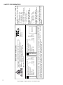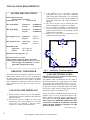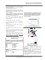
1
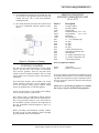
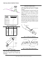
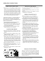
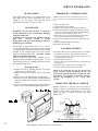
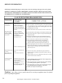
INSTALLATION AND OPERATING INSTRUCTIONS
ASC – 42
HEAT RECIRCULATING GAS FIREPLACE
MODEL : ASC42 – NG Natural Gas
ASC42 – LP Propane
These gas appliances have been tested in accordance
with National Safety Standards, and have been certified
by Warnock Hersey for installation & operation as
described in these Installation and Operating
Instructions in the United States.
Check with your local building code agency before you
begin your installation to ensure compliance with local
codes, including the need for “permits” and follow-up
inspections. If any problems are encountered regarding
code approvals, or if you need clarification of any of the
instructions contained here, contact:
ALPINE GAS FIREPLACES
#801-768-8411 / www.alpinefireplaces. com
WARNING:
If the information in these
instructions are not followed exactly, a fire or
explosion may result causing property
damage , personal injury or loss of life.
Improper installation, adjustment, alteration,
service or maintenance can cause property
damage, personal injury or loss of life.
FOR YOUR SAFETY
Do not store or use gasoline or other
flammable vapors and liquids in the vicinity
of this or any other appliance.
WHAT TO DO IF YOU SMELL GAS:
• Do not try to light any appliance.
• Do not touch any electrical switch; do
not use any phone in your building.
• Immediately call your gas supplier from
a neighbor’s phone. Follow the gas
supplier’s instructions
• If you cannot reach your gas supplier,
call the fire department.
INSTALLATION AND SERVICE MUST
BE PERFORMED BY A QUALIFIED
INSTALLER, SERVICE AGENCY OR THE
GAS SUPPLIER.
INSTALLER: PLEASE LEAVE THIS MANUAL WITH THE CUSTOMER
HOMEOWNER: PLEASE KEEP THESE INSTRUCTIONS FOR FUTURE REFERENCE
Alpine Gas Fireplaces
782 West State Street
Lehi, Utah 84043
12/06
Tested by:
TABLE OF CONTENTS
SAFETY INFORMATION
Safety Label ........................................2
Before Starting....................................3
General Safety Information ................3
System Specifications.........................4
Derating the Burner ............................4
OPERATING INSTRUCTIONS
Operation Instruction Plate .............. 20
Lighting Procedure........................... 21
Control Valve Operation .................. 21
Shutdown Procedure ........................ 21
FIREPLACE MAINTENANCE
INSTALLATION REQUIREMENTS
Locating the Fireplace ........................4
Gas Line Installation...........................5
Clearances...........................................5
Mantel Clearances ..............................5
Hearth Materials .................................5
Framing and Finishing ........................6
VENTING
Venting Planning ................................7
Venting Components List ...................7
Venting Chart / Direct Vent................8
Horizontal /Vertical Terminations ......9
Horizontal Venting Installation ........11
Vertical Venting Installation.............12
Maintenance Instructions .............. 21
Cleaning Brass Trims....................... 21
Cleaning the Glass............................ 22
Cleaning the Logs ............................ 22
SERVICE
Log Replacement ............................. 22
Inspecting the Pilot........................... 22
Replacement Parts List..................... 23
TROUBLESHOOTING GUIDE
Gas Control System.......................... 24
ELECTRICAL SYSTEM
Electrical System Installation ...........13
Millivolt System ...............................14
INSTALLATION INSTRUCTIONS
Securing the Fireplace ......................14
Installing the Venting .......................14
Aeration Adjustment.........................17
Log Installation.................................18
Door Assembly Installation .............19
Remote Control (Optional) ...............19
Wall Thermostat (Optional)..............19
Alpine Supply Company 42 Direct Vent Gas Fireplace
1
2
WC
WC
WC
DMS
BTU/h
BTU/h
Ft
Model ASC42-LP
Model ASC42-NG
Minimum supply pressure
11”
Manifold pressure high
10.0”
Manifold pressure low
5.8”
Orifice Size
# 55
Minimum input
16,000
Maximum input
23,000
Altitude
2500 – 6500
PROPANE : Series ASC42-LP
WC
WC
WC
DMS
BTU/h
BTU/h
Ft
Field Converted
Put Label Here
Made in USA
Alpine Gas Fireplaces
Lehi, Utah
Alpine Supply Company 42 Direct Vent Gas Fireplace
VENTED GAS FIREPLACE HEATER NOT FOR USE WITH SOLID FUEL.
Use Only Simpson Dura-Vent GS System . Use only Simpson vent cap #0991 on vertical applications. This appliance must be installed in
accordance with the manufacturer’s installation instructions and with local codes, if any; if not, follow the current ANSI Z223.1 in the USA. This
vented gas fireplace heater is not for use with air filters. # 432-917 Fan Kit may be used. Electrical supply 120VAC, .62 Amps, 60Hz.
Minimum supply pressure
5”
Manifold pressure high
3.5””
Manifold pressure low
.8”
Orifice Size
# 43
Minimum input
13,400
Maximum input
26,000
Altitude
2500 – 6500
NATURAL GAS : Series ASC42-NG
Listed:
DIRECT VENT GAS FIREPLACE HEATER
Tested to: ANSI Z21.88.2002./CSA2.33a-2002
VENTED GAS FIREPLACE HEATER.
Report No. 3031549 2/02
Serial Number: ALPINE SUPPLY COMPANY ASC 42
DO NOT REMOVE THIS LABEL
This appliance may be recessed until the
front of the unit is flush with any facing
material.
The Flue requires the following
minimum clearances on Vertical Vent:
1 1/2” to combustibles – Vertical
The Flue requires the following
minimum clearances on Horizontal
Vent:
2” to combustibles – Top
1” to combustibles – Sides
1/2” to combustibles – Bottom
This appliance must be installed in
accordance with the following minimum
clearances:
1 1/2” to combustibles – Top
1/2” to combustibles – Sides
1/2” to combustibles – Back
0” to combustibles – Bottom
18” Top of stove – Ceiling (Flex Vent)
14” Top of stove – Ceiling (Rigid Vent)
6” to combustible Mantel
( projecting a maximum of 6” )
SAFETY INFORMATION
INSTALLATION REQUIREMENTS
IMPORTANT:
SAVE THESE INSTRUCTIONS
The Alpine Supply Company Direct Vent Fireplace
must be installed in accordance with these
instructions. Carefully read all the instructions in this
manual first. Consult the “authority having
jurisdiction” to determine the need for a permit prior
to starting the installation. It is the responsibility of
the installer to ensure this fireplace is installed in
compliance with the manufacturer’s instructions and
all applicable codes.
BEFORE YOU START
Safe installation and operation of this appliance
requires common sense, however, we are required by
INSTALLATION AND REPAIR SHOULD BE
DONE BY A QUALIFIED SERVICE PERSON.
THE APPLIANCE SHOULD BE INSPECTED
BEFORE USE AND AT LEAST ANNUALLY BY
A PROFESSIONAL SERVICE PERSON. MORE
FREQUENT CLEANING MAY BE REQUIRED
DUE TO EXCESSIVE LINT FROM
CARPETING, BEDDING MATERIAL, ETC. IT
IS IMPERATI VE THA T CONTRO L
COMPARTMENTS,
BURNERS
AND
CIRCULATING AIR PASSAGEWAYS OF THE
APPLIANCE BE KEPT CLEAN.
DUE TO HIGH TEMPERATURES, THE
APPLIANCE SHOULD BE LOCATED OUT OF
TRAFFIC AND AWAY FROM FURNITURE
AND DRAPERIES.
WARNING: FAILURE TO INSTALL THIS
APPLIANCE CORRECTLY WILL VOID YOUR
WARRANTY AND MAY CAUSE A SERIOUS
HOUSE FIRE.
CHILDREN AND ADULTS SHOULD BE
ALERTED TO THE HAZARDS OF HIGH
SURFACE TEMPERATURES, ESPECIALLY
THE FIREPLACE GLASS, AND SHOULD STAY
AWAY TO AVOID BURNS OR CLOTHING
IGNITION.
YOUNG
CHILDREN
SHOULD
BE
CAREFULLY SUPERVISED WHEN THEY ARE
IN THE SAME ROOM AS THE APPLIANCE.
CLOTHING OR OTHER FLAMMABLE
MATERIAL SHOULD NOT BE PLACED ON
OR NEAR THE APPLIANCE.
GENERAL SAFETY INFORMATION
1) The appliance installation must conform with
local codes or, in the absence of local codes, with
the current National Fuel Gas Code, ANSI
Z223.1 installation code.
2) The appliance when installed, must be electrically
grounded in accordance with local codes, or in
the absence of local codes with the current
National Electrical Code, ANSI/NFPA 70.
3) This appliance must be connected to the specified
vent and termination cap to the outside of the
building envelope. Never vent to another room or
inside a building. Make sure that the vent is fitted
as per venting instructions.
4) Inspect the venting system annually for blockage
and any signs of deterioration.
5) Venting terminals shall not be recessed into a
wall or siding.
6) Any safety glass removed for servicing must be
replaced prior to operating the appliance.
7) To prevent injury, do not allow anyone who is
unfamiliar with the operation to use the fireplace.
8) Wear gloves and safety glasses for protection
while doing required maintenance.
9) Be aware of electrical wiring in locations in walls
and ceilings when cutting holes for termination.
10) Under no circumstances should this appliance be
modified. Parts that have been removed for
servicing should be replaced prior to operating
this appliance.
11) Installation and any repairs to this appliance
should be done by a qualified service person. A
professional service person should be called to
inspect this appliance annually. Make it a practice
to have all of your gas appliances checked
annually.
12) Under no circumstances should any solid fuels
(wood, paper, cardboard, coal etc.) be used in this
appliance.
13) The appliance area must be kept clear and free of
combustible materials, gasoline and other
flammable vapors and liquids.
14) If the pilot goes out for any reason, turn the
control knob to the off position. Wait five
minutes before attempting to re-light pilot.
15) Never obstruct the flow of ventilation and
combustion air to the fireplace.
Alpine Supply Company 42 Direct Vent Gas Fireplace
3
INSTALLATION REQUIREMENTS
SYSTEM SPECIFICATIONS
Burner Inlet Orifice Sizes:
(2500 TO 6500 feet altitude )
Natural Gas: #43
Propane: #55
Max. Input Rating –
Natural Gas
Propane
26,000 Btu/h
23,000 Btu/h
Min. Input Rating –
Natural Gas
Propane
13,400 Btu/h
16,000 Btu/h
Min. Supply Pressure
Natural Gas
Propane
5.0” w.c.
11.0” w.c.
Max. Supply Pressure
Natural Gas
Propane
7.0” w.c.
13.0” w.c.
Manifold Pressure
Natural Gas
Propane
3) If the appliance is to be installed on carpeting,
combustible vinyl tiling, or any other combustible
surface other than wood flooring, a 1/2” wood panel
must be installed on top of the existing flooring. The
panel must extend the full width and depth of
appliance.
4) The ASC-42 fireplace can be installed into many
different applications. See Figure 1 for examples.
5) Lay out fireplace dimensions on installation site
before proceeding with installation. This will ensure
proper clearances and assist in identifying potential
problems before installation.
6) Make sure to review the vent termination system
requirements before proceeding.
3.5” +/-0.2” w.c.
10” +/-0.2” w.c.
Minimum Gas Line Pipe Size: 1/2”
Electrical: 120 V.A.C. System
(Optional blower) Amperage Rating: 0.62 Amps
Venting: Simpson Duravent Direct Vent (4” x 6 5/8”)
Must use high wind termination on vertical
applications (Simpson part # 0991)
DERATING THE BURNER
The fireplace has been designed to operate at elevations
approximately 4500 ft. above sea level. No deration of
the burner needs to occur unless the fireplace is installed
at elevations below 2500 ft. or above 6500 ft. The burner
orifice should then be adjusted one drill size smaller for
higher elevations and one drill size larger for lower
elevations.
LOCATING THE FIREPLACE
1) When selecting a location for your Gas Fireplace,
ensure that the clearances outlined in this manual are
adhered to strictly.
2) The fireplace must be installed on a flat, solid,
continuous surface. If the appliance is to be raised
off the floor on a platform, it must be securely
fastened to a sturdily constructed platform.
Fig. 1 – Installation Placement Options
GAS LINE INSTALLATION
IMPORTANT: Gas piping should be installed only by
trained and qualified technicians.
The appliance and its individual shut off valve must be
disconnected from the gas supply piping system during
any pressure testing of that system in excess of 1/2” psi.
The appliance must be isolated from the gas supply piping system by closing its individual shutoff valve during
any pressure testing of the gas supply piping system at
test pressures equal to or less than 1/2” psi.
The gas line must be brought through the left side of the
appliance. The 1/2” service gas line must connect to the
flexible appliance connector which is attached to the
main control valve. DO NOT MAKE THIS CONNECTION UNTIL ALL PRESSURE TESTING OF THE
GAS PIPING SYSTEM IS COMPLETE. FAILURE
TO DO SO WILL RESULT IN DAMAGE TO THE
MAIN CONTROL VALVE.
( Continued on next page )
4
Alpine Supply Company 42 Direct Vent Gas Fireplace
INSTALLATION REQUIREMENTS
Gas piping must conform to the current National Fuel
Gas Code, ANSI Z223.1.
Always consult with the local code official for additional
local codes applicable in your area.
IMPORTANT: Always check for gas leaks with a soap
and water solution or gas leak detector. Never use open
flame for leak testing.
NOTE: To properly check gas pressure, both inlet
and manifold pressures should be checked using the
valve pressure ports on the control valve.
The manifold pressure is controlled by a regulator built
into the gas control, and should be checked at the
pressure test point.
NOTE: If the appliance is to be installed on carpeting,
vinyl tiling, or any other combustible material other
than wood flooring, the appliance must be installed on
a metal or wood panel extending the full width and
depth of the appliance.
1) Make sure the valve is in the “ OFF” position.
2) Loosen the “IN” and/or “OUT” pressure tap(s),
turning counterclockwise with a 1/8” wide flat
screwdriver.
3) Attach manometer to “IN” and/or “OUT” pressure
tap(s) using a 5/16” ID hose.
Fig. 2 – Clearances for appliance facing
4) Light the pilot and turn the valve to the “ON”
position.
5) The pressure check should be carried out with the unit
Burning and the setting should be within the limits
specified on the safety label.
6) When finished reading the manometer, turn off the gas
Valve. Disconnect the hose and tighten the screw
(clockwise) with a 1/8” flat screwdriver. Note: screw
should be snug. But do not over tighten
CLEARANCES
IMPORTANT: Clearances listed in this manual must
be adhered to strictly. Failure to maintain these listed
clearances of the fireplace and venting system can result in a house fire.
Clearance to Combustibles from:
Back
Side
Floor
Top
0” to spacers
0” to spacers
0” wood surface
0” to spacers
Facing and Trim Clearances:
Mantel
6” (see mantel clearance – Fig. 3)
Side Mantel Leg 6”
Ceiling
21” Flex
18” S.D.
Fig. 3 – Mantel Clearances
HEARTH MATERIALS
A Hearth is not mandatory with the ASC-42 series
fireplace, but is recommended for aesthetics and for
added safety .
Non-combustible materials such as Tile, Brick, Rock, and
Slate are recommended. The appliance should not be
installed over existing carpeting.
In constructing a hearth, hearth material thickness must
be taken into consideration. Avoid using any material that
will block the front of the valve access door at the bottom
of the fireplace.
Alpine Supply Company 42 Direct Vent Gas Fireplace
5
FRAMING & FINISHING
FRAMING & FINISHING
1) Determine the total thickness of the facing material
(e.g. drywall plus ceramic tiles) to allow the finished
surface to be flush with the front of the unit. The
ASC-42 series may be installed with the facing
material adjacent to the finished flange.
Fig. 6 – Framing Side View
42 5/8"
30 1/8"
Fig. 4 – Facing Options
2) Frame in the enclosure for the fireplace. A rough
framed opening of 33” high by 38” will be required
for installation (see figure 5-7).
60 1/4"
Fig. 7 – Corner Installation
NOTE: The fireplace does not have to be
completely enclosed in a chase. The clearance on
the top of the fireplace is 0” to the spacers. You
must maintain clearance from the vent
components to combustibles.
IMPORTANT: The header above the framed
opening must be placed upright so as to allow for
proper clearance of the vent pipe. See figure 6.
Note: header is turned on its
side to maintain clearance
to the vent pipe
37"
height
42"
width
Fig. 5 – Framed Opening
6
3) If the fireplace is to be installed into an exterior wall.
The enclosure or fireplace chase should be insulated
to the same degree as the home. Check with your
local building official for any additional local
requirements (e.g. vapor barriers, drywall).
NEVER INSULATE THE FIREPLACE ITSELF
4) The top of the fireplace should be no closer than 18”
With Simpson Duravent pipe, or 21” with flex pipe
to the ceiling.
Alpine Supply Company 42 Direct Vent Gas Fireplace
VENTING REQUIREMENTS
5) Non-combustible material may be brought up to the
top and sides of the appliance and be covered with
ceramic tile, brick, rock, or other non-combustible
finishing materials.
6) Steel studs should be used where the clearance from
the vent to combustible materials cannot be maintained.
Figure 8– Clearance to Venting
VENTING PLANNING
The ASC-42 uses Simpson Duravent Co-Axial venting
systems. The inner tube vents products of combustion
away from the appliance, while the outer tube draws
outside air into the combustion chamber. This is a closed
system and uses no air from the interior of the home for
combustion.
Never attach this fireplace vent to another vent serving
another appliance. Each direct vent gas appliance must
use its own separate venting system. Common venting
systems are prohibited for use with this appliance.
SIMPSON DURAVENT
VENTING COMPONENTS LIST
(4”x 6 5/8”)
Stock #
Description
0945
0990
11053
0943
0943S
11088
11063
0917
0906
0904
0903
0902
0991
0984
0942
0982
0981
0950
45 Degree Elbow
90 Degree Elbow
Storm Collar
Standard Flashing 0/12 – 5/12
Steep Flashing
6/12 – 12/12
Wall Strap
Firestop Spacer
17” - 24” Adjustable pipe
12” pipe
24” pipe
36” pipe
48” pipe
Vertical Termination Cap
Horizontal Termination Cap
Wall Thimble
14” Snorkel Termination Cap
36” Snorkel Termination Cap
Vinyl Siding stand-off
Parts not supplied by Simpson
09364
09366
Vent Guard
Masonry wall stand-off
In all cases, adequate combustion and ventilation air must
be available for the fireplace. Never block the termination
cap. Make sure foliage does not grow around the termination cap. In all cases, follow the clearances listed on page
8 of this manual.
NOTE: Never connect this gas appliance to a chimney
flue serving a separate solid-fuel burning appliance.
Always vent the fireplace to the outside of the building.
Never vent into a garage or enclosed area.
This venting system, in combination with the ASC-42
Direct Vent Gas Fireplace, has been tested and listed as a
direct vent gas fireplace heater by I.T.S. The location of
the termination cap must conform to the requirement in
the Vent Termination Locations diagram on page 8 of
this manual.
Before proceeding with installation, carefully examine
the chart on page 8 of this manual for options regarding
proper placement of the vent termination.
Alpine Supply Company 42 Direct Vent Gas Fireplace
7
8
V
P
E
V
M
24"
V Vent terminal
B
F
V
B
B
V
Openable
V
A
K
B
A
24"
Vertical
Termination
H
J
N
Area where terminal is not permitted
B
V
18"
V
L
A
Matthew Hobby is the coolest!
- A vent shall not terminate directly above a sidewalk
or paved driveway which is located between two single
family dwellings and serves both dwellings.
- Only permitted if veranda, porch, deck, or balcony is
fully open on a minimum of two sides beneath the floor.
- If the vent termination is accessible a certified guard
should be installed.
- Local codes or regulations may require different
clearances.
Note:
M= Clearance above paved sidewalk or a paved driveway located on
public property (min. 84”)
N= Clearance under a veranda, porch, deck, or balcony (min. 12”)
P= Clearance to obstructions in front of the termination such as bushes,
fences, sheds, decks, other structures is (24”)
A Air supply outlet
Openable
V
B
Fixed
Closed
C
V
V
A
G
Inside
corner detail
A= Clearance above grade, veranda, porch, deck, or balcony (min. 12”)
B= Clearance to window or door that may be opened (12”)
C= Clearance to permanently closed window (12”)
(recommended to prevent condensation on window)
D= Vertical clearance to ventilated soffit located above the terminal
within a horizontal distance of (24”) from the centerline of the
terminal (min. 18”)
E= Clearance to unventilated soffit (min. 15”)
F= Clearance to outside corner (19”)
G= Clearance to inside corner (12”)
H= Not to be installed above a meter / regulator assembly within (3’)
horizontally from the centerline of the meter.
J= Clearance to service regulator vent outlet (min. 36”)
K= Clearance to non-mechanical air supply inlet to building or the
combustion air inlet to any other appliance (12”)
L= Clearance to a mechanical air supply inlet (36”)
D
Vertical
Termination
VENTING REQUIREMENTS
VENT TERMINATION LOCATIONS
Alpine Supply Company 42 Direct Vent Gas Fireplace
VENTING REQUIREMENTS
ASC Direct Vent System ( Flex ) Horizontal Terminations Only
The venting systems, in combination with the ASC Direct Vent Gas Fireplace, have been tested and listed
as direct vent heater system by ITS. The location of the termination cap must conform to the requirements in
the Vent Terminal Locations diagram on page # 8.
ASC. Direct Vent ( Flex ) System Termination Kit
( Part # 09019 ) includes all the parts needed to install
the ASC with A maximum run of 4 feet.
1) 7” dia. flexible liner ( 4 ft. length )
2) 4” dia. Flexible liner ( 4ft. Length )
This diagram shows all allowable maximum combinations of
horizontal runs for flexible vent systems. A maximum of 3'
horizontal run with a maximum vent length of 8' is the limitation. The maximum rise is 7' vertical with a 1'
horizontal run.
If longer runs are needed the ASC Direct Vent System
(flex) # 09021 includes all the parts needed to install the
ASC with a maximum 8’ run.
1) 8’ dia. Flexible liner (8 ft. length)
3) Spring spacers (4)
2) 4” dia flexible liner (8 ft. length)
4) Firestop (1)
3) Spring spacers (6)
5) Termination cap (1)
4) Firestop (1)
6) Screws (12)
5) Termination cap (1)
7) Tube of Mill Pac (1)
6) Screws (12)
8) 4” clamps (2)
7) Tube of Mill Pac (1)
9) Flexible vent adapter (1)
8) 4” clamps (2)
9) Flexible vent adapter
Notes:
1) Liner sections should be continuous without any seams.
2) Only Flex Kits purchased from Alpine Gas Fireplace may be used for Flex installations.
Alpine Supply Company 42 Direct Vent Gas Fireplace
9
VENTING REQUIREMENTS
SIMPSON DURAVENT VENTING
Horizontal or Vertical Terminations
The Simpson Dura Vent System offers a complete line of component parts for both horizontal and vertical installations.
Read installation instructions included within the termination cap box.
The following is a list of components required for a basic
horizontal termination installation.
The following is a list of components required for a basic
vertical termination installation.
1
1
1
1
1
1
1
1
1
2
1
Horizontal Termination Cap
90 Degree Elbow
Flue Adapter (installed on unit from factory)
Wall Penetration Shield
24” Pipe
17” -24” Adjustable Pipe
If vinyl or aluminum siding is to be used, a vinyl siding
standoff should also be used. If brick or rock is to be
applied to the exterior of the home, make sure that the
cap is extended to the thickness of the brick or rock. The
Termination must never be recessed into the wall.
10
Vertical Termination Cap
Storm Collar
Roof Flashing *
36” vent pipe
Flue Adapter (installed on unit from factory)
* If the home has a chase projecting above the roof line, a
roof flashing will not be needed.
The vertical termination should project above the finished
chase a minimum of 10”. See local codes for other venting requirements in your area.
Alpine Supply Company 42 Direct Vent Gas Fireplace
VENTING REQUIREMENTS
VENTING REQUIREMENTS – HORIZONTAL TERMINATIONS
SIMPSON DURA-VENT DIRECT VENT SYSTEM
(FOR BOTH PROPANE AND NATURAL GAS)
The diagram shows all allowable combinations of vertical runs with horizontal terminations, using one 90 deg. Elbow.
A vent guard (part # 09364) should be used whenever the termination is lower than the specified minimum
of your local building codes.
Firestops are required at each floor level and whenever passing through a wall.
All ASC-42 fireplaces use Simpson 4” x 6 5/8” venting. Other Simpson sizes are not approved for use with
the ASC-42.
Alpine Supply Company 42 Direct Vent Gas Fireplace
11
VENTING REQUIREMENTS
VENTING REQUIREMENTS – VERTICAL / HORIZONTAL TERMINATIONS
SIMPSON DURA-VENT DIRECT VENT SYSTEM
(FOR BOTH PROPANE AND NATURAL GAS)
The diagrams show all allowable combinations of straight vertical, offset to vertical, and offset to horizontal terminations with Simpson Dura–Vent systems. Maximum of two 45 deg. elbows are allowed.
• Horizontal venting must be
supported every 3 feet
• Firestops are required at each
floor level and whenever
passing through a wall.
If length “B” is increased, length “A” must
be decreased by a corresponding amount.
12
Alpine Supply Company 42 Direct Vent Gas Fireplace
ELECTRICAL SYSTEM
INSTALLING ELECTRICAL CONTROLS
AND WIRING
A 110 volt power supply (grounded) is required to
operate the optional blower system. The blower
controller (optional) should be mounted in a wall within a
few feet of the appliance, in a convenient location. Once
the location of the blower controller has been identified,
mount a metal or plastic electrical box and route the
wires from the blower to the electrical box. The wiring
needs to be routed from the control location to the
appliance. The appliance internal electrical box is located
on the right side of the appliance. (See figure 9). Use only
Blower Kit #431917 Installation instructions for the
blower kit are included with the kit.
NOTE: even if the blower is not purchased with the unit,
it is still a good idea to hardwire the appliance in case the
fan is installed at a later date. DO NOT LEAVE THIS
CONNECTION LIVE UNTIL THE FAN IS
INSTALLED.
When installing the low voltage wiring. It is essential that
the wires be marked so as to never have 110 volt /24 volt
power attached to them. If power is attached to the
control valve, damage will certainly occur.
The appliance generates the millivoltage needed to
operate the gas control system. A standard wall toggle
switch or a listed wall thermostat may be used to control
the main gas valve.
The millivolt system has limitations on the distance it can
be installed from the fireplace. The greater the distance
from the fireplace, the larger the wire size must be to
prevent loss of the millivoltage. See the table below for
recommendations.
Maximum Length
Wire Guage
9’
22 ga.
13’
20 ga.
20’
18 ga.
30’
16 ga.
50’
14 ga.
Millivolt thermostats and remote controlled millivolt
thermostats are available from your Alpine dealer.
See figures 10, 11 and 12 for additional information
about wiring your appliance.
Note: Local codes need to be followed when installing
any electrical appliance. If conflicts between this
manual and local electrical codes exist. Local codes
always prevail.
Ground for
mobile home
Green (Ground)
White (Neutral)
Green
120 VAC
60HZ
(*by others)
Black (Live)
Fan
NOTE: Do not allow any wiring to rest against the
appliance as fire danger may result.
OFF
White
(*Supplied by others
install according to
local code)
Black
NOTE: Proper grounding must be maintained on the
appliance and on the blower assembly.
ON
(*by others)
Fig. 9 – Typical Electrical
Black
White
(*by others)
Thermodisc
Fig. 10– Wiring
Schematic
NOTE: DO NOT connect any electricity to the main
gas control valve wiring. Valve damage will certainly
occur.
The appliance is equipped with a millivolt system that
controls the main gas control valve. A low voltage two
strand wire set needs to be routed from the main gas
control valve to the desired position of the wall switch.
Some prefer the switch be co-located with the blower
controller. If this choice is made, a DIVIDED double
gang electrical box must be installed. (A standard (nondivided) double gang box cannot be used.)
______Fig. 11 – Proper Grounding Technique_______
Alpine Supply Company 42 Direct Vent Gas Fireplace
13
INSTALLATION INSTRUCTIONS
VENTING – HORIZONTAL
Install the vent system according to the instructions
included in the venting kit received with the fireplace.
1. With the unit in the desired location, check to
determine if wall studs or roof rafters will obstruct the
venting system when attached. If this is the case, you
may want to adjust the location of the unit or consult
with your framing contractor for options in adjusting the
framing.
Fig. 12– Millivolt Schematic Wiring
SECURING THE FIREPLACE
The Fireplace is equipped with four nailing tabs, which
Must be bent out before inserting into framed opening
(See Figure 13)
2. To properly assemble the Simpson pipe and fittings on
a direct vent system, Mill-pac brand sealant must be
placed between the inner collars of the pipe (see figure
14). Slip the pipe together and twist to lock. After the
pipe is assembled. Carefully wrap the outer seam with
aluminum tape (or seal with silicone). An airtight seal
must be created.
NOTE: All pipe joints must be sealed with Mill-pac
sealant and aluminum tape or Silicone.
Fig. 14– Applying Sealant
NOTE: Horizontal runs must be supported every
three feet. Wall straps should be used for this support.
Fig. 13– Securing the fireplace
3. A 10” x 10” square hole must be cut in the exterior
wall. The centerline of this hole should align with the
centerline of the horizontal pipe. Cut and frame the 10”
hole to support the venting (see figure 24).
NOTE: The vent must have a 1/4 inch rise for each 1
foot of run towards the termination. NEVER allow
the vent to run downward. This will cause high temperatures and may cause a fire.
NOTE: The location of the horizontal vent termination on an exterior wall must meet all local and national building codes. See page 8 of this manual for
proper terminal locations.
14
Alpine Supply Company 42 Direct Vent Gas Fireplace
INSTALLATION INSTRUCTIONS
Make Sure Arrow
is pointing up.
Wall Penetration
Heat Shield
11" x 11" Opening
Vinyl Siding Stand-off
Fig. 15– Termination Framing
Fig. 16– Penetration Shield
NOTE: The arrow located on the face of the
termination must be pointing up.
NOTE: Clearances to combustibles from the vent pipe
must be adhered to. See the table below for proper
clearances.
Sheet Metal Screws
Horizontal Venting Clearances
TOP OF PIPE
SIDES OF PIPE
BOTTOM OF PIPE
2” to combustibles
1” to combustibles
1/2” to combustibles
Attaching Straps
NOTE: IF installing termination on a siding covered
wall, a vinyl standoff or furring strips must be used to
ensure that the termination is not recessed into the
siding.
Fig. 17– Attaching the Termination
4. Before connecting the horizontal run of vent pipe to
the vent termination, slide the Wall Penetration Heat
Shield over the vent pipe (see figure 16, 18).
Wood Screws
5. Slide the appliance and vent assembly towards the
wall, carefully inserting the vent pipe into the vent cap
assembly. The vent pipe must extend into the vent cap,
resulting in minimum pipe overlap of 1-1/4 inches.
Secure the connection between the vent pipe and the vent
cap by attaching the two sheet metal strips that extend
from the vent cap assembly into the outer wall of the vent
pipe. Use two sheet metal screws to connect the strips to
the pipe section (see figure 17).
Fig. 18– Finishing the Heat Shield
Alpine Supply Company 42 Direct Vent Gas Fireplace
15
VERTICAL TERMINATION
1. Maintain the 1” clearances to combustibles when
passing through ceilings, roofs, enclosures, attic rafters,
or other nearby combustible surfaces. Do not pack air
spaces with insulation. See the diagrams on page 11 of
this manual for the maximum vertical rise of the venting
and the maximum horizontal offset limitations.
2. With the gas appliance in its desired location, drop a
plumb bob from the ceiling to the position of the
appliance flue exit and mark the location where the vent
will penetrate the ceiling. Drill a small hole at this point.
Next, drop a plumb bob from the roof to the hole
previously drilled in the ceiling and mark the spot where
the vent will penetrate the roof. Determine if ceiling
joists, roof rafters, or other framing will obstruct the
venting system. You may chose to relocate the fireplace
or offset the venting to avoid cutting framing members
(see figures 19 and 20).
Plumbers Tape
Wall Strap
45 degree
Elbow
Firestop
See Offset Table on page 11 for additional offset details.
Fig. 20– Venting Offsets
10" x 10" Square
Hole
Flashing
Framing
Firestop
Spacer
Firestop
Fig. 21– Firestop Installation
5. Cut a hole in the roof centered on the small drilled hole
placed in the roof in Step 2. The hole should be of
sufficient size to meet the minimum requirements for
clearance to combustibles of 1”.
Fig. 19– Vertical Venting
3. A Firestop spacer must be installed in the floor or
ceiling of every level. To install the Firestop spacer in a
flat ceiling or wall, cut a 10 inch square hole. Frame the
hole as shown in Figure 21 and install the firestop.
4. Assemble the desired lengths of pipe and elbows.
Ensure that all pipes and elbow connections are in the
fully twist–locked position and sealed with Mill-Pac
brand sealant on the inside collar and aluminum tape on
the exterior. An air tight must be created.
16
6. Continue to complete the assembly of the pipe lengths.
See figure 22 for proper vent height projecting through
the roof.
7. Ensure that the vent is vertical and secure the base of
the flashing with roofing nails. Slide the storm collar over
the pipe section and seal with a mastic type sealant.
8. Install the vent cap by twist locking it in place.
Alpine Supply Company 42 Direct Vent Gas Fireplace
INSTALLATION INSTRUCTIONS
AERATION ADJUSTMENT
Vent Height
Roof Pitch
Flat to 9/12
9/12 to 10/12
10/12 to 11/12
11/12 to 12/12
12/12 to 14/12
14/12 to 16/12
16/12 to 18/12
18/12 to 21/12
Minimum Vent Height
Above Roof Line
2’
2-1/2’
3-1/4’
4’
5’
6’
7’
8’
NOTE: The following assumes that the gas line has
been connected and leak tested by a qualified
technician.
The primary air adjustment is preset at the factory. Little
or no adjustment may be required for natural gas.
Propane will perform very differently at different
altitudes and from different fuel suppliers. Some
adjustment will most likely be needed for an appliance
burning propane.
The flame should have a blue base with yellow tips. A
dark orange flame with sooting and black smoke
indicates a lack of primary air. The primary air shutter is
located in the firebox under left hand side of the burner.
Adjust the primary mixture by loosening the set screw on
the air shutter and increasing the opening for more air
and a bluer / cleaner flame, or by closing the air shutter
for a more yellow flame. See figures 24 and 25 for proper
flame characteristics.
Venturi
Fig. 22– Vent Height Table
Offset
Pipe Length (L)
Height
Venturi Set Screw
4-3/4”
9”
11-1/4”
13-1/4”
21-3/4”
30-1/4”
38”
0”
6”
9”
12”
24”
36”
48”
13-1/4”
17-1/2”
19-1/2”
21-3/4”
30-1/4”
39”
47”
Fig. 24– Primary Air Adjustment
YELLOW TIPS
L
BLUE FLAME
Height
BURNER BASE
Offset
Fig.23– Offset Table
Fig. 25– Proper Flame Characteristics
NOTE: If the pipe is to pass through any closets or
storage spaces, the vent must be enclosed. The vent
must never be allowed to come in contact with
combustibles
Alpine Supply Company 42 Direct Vent Gas Fireplace
17
LOG INSTALLATION
NOTE: Proper log installation is very important.
Read the instructions below carefully and refer to the
diagrams. If the logs are broken do not use the
fireplace until they are replaced. See the replacement
parts list in this manual to order the proper
replacement logs. The logs are fragile and must be
handled with care. DO NOT FORCE THE LOGS
INTO POSITION.
Fig. 28–Rear & Right & Left Twig
3. Place the right hand side twig, with the split face
Rearward, onto the pin and then push back until it hits the
The rear stop. ( See Figure 28 )
Fig. 26– Rear Log Placement
1. Place the larger log on the grate centered and against
The wall. ( See figure 26 )
Fig. 29–Rear & Right & Left Twig
4. Place the left hand side twig, with the split face
forward, onto the pin and then push back until it hits
the Rear stop. ( See Figure 29 )
Fig. 27– Rear & Right Twig
2. Place dime sized pieces of ember material around
Center burner ports. Use caution not to cover burner
Ports.
18
Fig. 30– Front Twig
5. Place the small twig in front of the left hand side twig,
its notch straddling the second from the left andiron and
pushed fully forward. The logs must be positioned properly to create the proper burning pattern. ( See Figure 30 )
Alpine Supply Company 42 Direct Vent Gas Fireplace
INSTALLATION INSTRUCTIONS
6. Ignite the pilot assembly and test fire the burner. The
flame should flow smoothly to all points on the burner.
If the burner does not burn from all ports. Turn the appliance off and contact your Alpine Dealer before using the
appliance.
REMOTE CONTROL (Optional)
An Alpine Remote Control Kit (08501) may be installed
on this fireplace. The remote control kit comes with a
hand held transmitter, a receiver, a wall mounting plate,
The remote control is thermostatically controlled so you
can set the fireplace to the desired room temperature, and
have that temperature maintained. The remote control is
battery powered and will require periodic maintenance to
keep the system working properly.
1. Choose a convenient location on the wall to install the
receiver unit. A 22 Cu.In electrical box may be used. Run
wires from the fireplace valve to the desired wall
location. See the millivolt lead table on page 14 of this
manual for maximum wire runs.
2. Connect the wires to the gas valve (see figure 32).
3. Follow the installation instructions included with the
remote control kit.
Thermopile
PILOT
TP TH
TP
TH
HI
LO
TO WALL SWITCH
REMOTE CONTROL
OR THERMOSTAT
Fig. 31– Door Assembly Installation
Fig.33– Gas Valve Connection
WALL THERMOSTAT (Optional)
Pull hook forward
and up to slot
on door bracket
Fig. 32– Door Locking Assembly
A wall thermostat may be installed if desired. Follow the
wire routing instructions on page 12 of this manual.
Alpine offers two types of wall mounted thermostats.
One is a basic heating type thermostat (part # 08260).
The other is a model (part # 08261). See your Alpine
dealer for additional information on the thermostats.
NOTE: If a Wall Thermostat is desired, there is no
need to install a wall junction box. The thermostat
wire will simply need to be routed to the desired
location of the wall thermostat and made accessible
through a small hole in the drywall. Both types of
thermostats are surface mounted on the finished wall.
They should not be installed until painting is
complete.
Alpine Supply Company 42 Direct Vent Gas Fireplace
19
OPERATING INSTRUCTIONS
FOR YOUR SAFETY READ BEFORE LIGHTING
This appliance must be installed in accordance with local codes, if any;
If not, follow the current ANSI Z223.1
WARNING: If you do not follow these instructions exactly, a fire or
explosion may result causing property damage, personal injury or loss of
life. Improper installation, adjustment, alteration, service or maintenance
can cause injury or property damage. Refer to the owner’s information
manual provided with this appliance. For assistance or additional
information consult a qualified installer, service agency or gas supplier.
A) This appliance has a pilot which must
be lighted by hand. When lighting the
pilot, follow these instructions exactly.
B) BEFORE LIGHTING smell all around
the appliance area for gas. Be sure to
smell next to the floor because some
gas is heavier than air and will settle
on the floor.
WHAT TO DO IF YOU SMELL GAS
−
−
Do not try to light any appliance
Do not touch any electrical switch, do
not use any phone in your building.
−
Immediately call your gas supplier from
a neighbors phone. Follow the gas
suppliers instructions.
−
If you cannot reach your gas supplier,
call the fire department.
C) Use only your hand to push in or
turn the gas control knob. Never use
tools. If the knob will not push in or
turn hand, don’t try to repair it, call
a qualified service technician. Force
or attempted repair may result in a
fire or explosion.
D) Do not use this appliance if any part
has been under water. Immediately
call a qualified service technician to
inspect the appliance and to replace
any part of the control system and
any gas control which has been
under water.
This appliance needs fresh air for safe
operation and must be installed so there are
provisions for adequate combustion and
ventilation air.
CAUTION: Hot while in operation. Do not touch. Keep children, clothing,
furniture, gasoline and other liquids having flammable vapors away. Keep
burner and control compartment clean. See installation and operating
instructions accompanying appliance.
LIGHTING INSTRUCTIONS
STOP! Read the safety information above on
this label.
1) Push in gas control knob slightly and turn
clockwise C to “OFF”. Knob cannot be
turned from “PILOT” to “OFF” unless
knob is pushed in slightly. Do not force.
2) Wait five (5) minutes to clear out any gas.
If you then smell gas STOP! Follow “B”
in the safety information above on this
label. If you don’t smell gas, go to the next
step.
3) Turn knob on the gas control
Pilot Burner
THERMOPILE
Clockwise to “OFF”
C
4) Push in control knob all the way and hold
in. Continually push and release the red
button on the spark ignitor until pilot
lights. Continue to hold the control knob
in for about 1/2 minute after the pilot is
lit. Release knob and it will pop back up.
Pilot should remain lit. If it goes out,
repeat steps 1 to 4. If knob does not pop
up when released, stop and immediately
call your service technician or gas supplier. If the pilot will not stay lit after
several tries, turn the gas control knob to
“OFF” and call your service technician or
gas supplier.
5) Turn gas control knob counterclockwise
D to “ON”
6) Use the toggle switch to operate main
burner.
TO TURN OFF GAS APPLIANCE
1) Push in the gas control knob slightly and
turn clockwise C to “OFF”. Do not force.
2) Turn off all electric power to the appliance
if service is to be performed.
DO NOT REMOVE THIS INSTRUCTION PLATE
20
Alpine Supply Company 42 Direct Vent Gas Fireplace
LX-999-1
OPERATING INSTRUCTIONS
OPERATING INSTRUCTIONS
SHUTDOWN PROCEDURE
1) The first fire in your fireplace will help cure the
painted surfaces. To ensure that the paint is properly
cured, it is recommended that you burn your fireplace
for at least four (4) hours the first time you . When
first operated, the unit will release an odor caused by
the curing of the paint and other components. Smoke
detectors may go off during this initial break-in period.
Open windows or doors in the area of the fireplace to
allow for ventilation during the break-in period.
1) Use the wall switch, thermostat or remote control to
turn off the main burner.
2) Turn the main gas control clockwise to the “OFF”
position
3) Turn off all electricity to the appliance if service/
maintenance is to be performed.
NOTE: When the fireplace is cold and the appliance is
first lit, it may cause condensation and fog the glass.
This condensation is normal and will disappear in a few
minutes as the glass heats up.
2) Read and understand these instructions completely
before attempting to operate this appliance.
3) Be sure that all items in this installation portion of this
manual have been properly completed in compliance
to local codes and this manual.
4) The unit should never be turn off and then on again
without a minimum of a 60 second wait.
LIGHTING PROCEDURE
1) Turn burner OFF using the “ON/OFF” switch or by
turning the thermostat or remote control to the “OFF”
position.
2) Turn gas control knob so indicator points to “OFF”
position and allow 5 minutes for any gas in the
combustion chamber to escape.
3) Turn the gas control knob counterclockwise so the
indicator points to the “PILOT” position. Depress the
gas control knob fully. Depress the igniter button
several times until the pilot lights. After approximately
one minute, release the gas control knob. The pilot
flame should continue to burn. If the pilot does not
remain lit, repeat operation allowing a longer period
before releasing gas control knob.
4) When the pilot stays lit, turn the gas knob further
counterclockwise to the “ON” position.
5) Use the wall switch, thermostat or remote control to
turn on the unit.
6) Rotate the flame height regulator to adjust the flame
height higher or lower.
FIREPLACE MAINTENANCE
1) Before performing any service on the appliance,
ensure the gas has been completely shut off, the unit
cooled, and the electricity shut off to the appliance.
2) The burner and valve control compartments must be
cleaned annually. A vacuum with a brush attachment
works well. The logs should be cleaned gently with a
soft bristle brush. The logs are fragile and are easily
damaged.
3) Clean the appliance with a damp cloth. Never use
abrasive cleaners. The glass should be cleaned with a
gas fireplace glass cleaner. The glass will slowly build
a thin white film on the inside. This film is normal
and can be removed using a fireplace glass cleaner
available at your local dealer.
4) The fireplace is finished with a high temperature paint.
If your fireplace needs to be repainted or touched up.
See your local dealer for StoveBright Paint.
5) The appliance and the venting system must be
inspected before use, and at least annually, by a
qualified field technician. The vent must be inspected
to ensure that the flow of combustion air and
ventilation air is not obstructed.
6) Do not use this appliance if any part has been under
water. Immediately call a qualified service technician
to inspect the appliance and to replace any part of the
control system and any gas control which have been
under water.
7) If the venting system is disassembled for any reason it
must be properly resealed as per the instructions in the
venting section of this manual. Never operate the
appliance if the venting system is not properly sealed.
BRASS & STAINLESS TRIMS
pilot
HI
on
off
LO
The brass or stainless trim on the fireplace require little
maintenance. If the pieces get fingerprints or dust buildup, you should use a damp cloth only for cleaning. DO
NOT use cleaners of any type on the brass or stainless.
Be sure to clean any fingerprints off of the unit BEFORE
turning the fireplace on.
Alpine Supply Company 42 Direct Vent Gas Fireplace
21
SERVICE INFORMATION
GLASS GASKET
If the glass gasket needs to be replaced, contact your
local dealer for the correct replacement part. Never
attempt to use any gasket, other than the correct
replacement on the glass. Use part # 07840.
GLASS PANEL
WARNING: Do not slam the door or strike the
ceramic panel with a heavy or hard object. Breakage
of the panel will result.
WARNING: Do not operate the appliance with the
glass front
removed, cracked, or broken.
Replacement of the glass panel should be done by a
qualified service technician.
Your fireplace is supplied with a 24 1/2” x 35 1/4”16” by
1/4” thick tempered glass. If your glass requires cleaning,
you should obtain an approved fireplace glass cleaner
available at your fireplace dealer. Do not use abrasive
cleaners to clean the glass panel. DO NOT CLEAN
THE GLASS WHEN IT IS HOT!
In the event that your glass breaks purchase your replacement from an authorized Alpine dealer. See the
replacement parts list for ordering information. Follow
the replacement steps below.
Replacing the Glass
1) Remove the door by releasing the glass clip springs
found in the valve chamber area.
2) Always where gloves to protect yourself from sharp
edges.
3) Remove all loose or damaged glass from the frame.
4) Insert the new glass panel with the gasket preinstalled
so that the liftable fold of gasket is facing inside the
fireplace.
5) Use the 4 existing Tinnerman glass clips to hold the
glass in place, with retaining tab under gasket fold
THERMOPILE / THERMOCOUPLE
“Caution: Label all wires prior to disconnecting when servicing
controls. Wiring Errors can cause improper and dangerous operation.”
1) Remove the glass door
2) Open the bottom valve chamber
3) Double check to make sure gas supply is turned off
4) Disconnect the thermocouple by loosening nut from the
valve with a 9mm wrench. Disconnect the thermopile by
loosening 2 screws marked TP on the valve.
5) Remove the two 1/4” screws holding the pilot assembly
in its bracket. Gently lift the pilot assembly up 2”.
6) Disconnect the thermopile and thermocouple with a 7/16”
wrench.
7) Replace the thermocouple or thermopile.
8) Reinstall in reverse order.
LOG REPLACEMENT
The fireplace must never be operated if the logs are broken
or damaged. To replace the logs follow the steps below.
1) Turn off the gas supply and allow the fireplace to cool
completely before servicing.
2) Open the glass door panel.
3) Gently remove the logs from the firebox. Be sure to note
their position.
4) Obtain the proper replacement for the broken log.
5) Replace the log set and close the door panel.
NOTE: It is critical that the logs are placed in the
proper locations. Improper positioning of logs may
create carbon build-up and will severely alter the unit’s
performance. Poor appliance performance caused by
improper log installation is not covered under
warranty.
INSPECTING THE PILOT / BURNER
Periodic inspection of the pilot and main burner is
required. Figure 25, located on page 16 of this manual,
illustrates proper flame characteristics for the main
burner. See figure 42 below for proper pilot flame
characteristics.
Pilot
Flame should
engulf the top
3/8" to 1/2"
Thermopile
Quick Drop out
Thermocouple
Fig. 34– Pilot Flame Characteristics
22
Alpine Supply Company 42 Direct Vent Gas Fireplace
PARTS LIST
REPLACEMENT
PARTS LIST
07622
07655
05149
07840
06624
04081
09232
08255
08251
04036
08991
3520A
04046
08400
04080
08216
04038
04039
08501
36533
35632
36516
36101
3622A
08261
08260
431-917
08218
Log Set (7 Logs)
Embers
Glass Clips
Glass Gasket
Glass
Door Spring Hook
Fan Speed Control
White Toggle Switch
White 2 Switch Plate
S.I.T. Valve Nat. Gas
S.I.T. Valve Propane Conversion
Burner – Nat Gas / Prop
Piezo Igniter
Double Gang Box
Door Extension Spring
Blower Assembly
Pilot Assembly –N.G.
Pilot Assembly– Propane
Remote Control
Vent Door
Valve Door
Glass Trim-Standard
Heat Deflector
Burner Grate
Set Back Thermostat
Thermostat
Fan Kit
Fan
Alpine Supply Company 42 Direct Vent Gas Fireplace
23
SERVICE INFORMATION
NOTE: Before troubleshooting the gas control system, be sure the external gas shut off is in the “ON” position.
WARNING: TO PREVENT INJURY OR PROPERTY DAMAGE, REMOVE THE GLASS PANEL FROM
THE APPLIANCE BEFORE DOING ANY WORK ON THE GAS CONTROL SYSTEM. FAILURE TO DO SO
COULD RESULT IN GAS BUILD-UP AND EXPLOSION.
GAS SYSTEM TROUBLESHOOTING
PROBLEM
POTENTIAL
CAUSES
Spark igniter will
not light pilot.
Piezo wire loose
Defective Piezo ignitor
Piezo wire grounding out
Electrode is grounding out
Electrode is sparking at wrong
location
•
Defective thermopile
Defective thermocouple
Thermopile / thermocouple
grounding out.
Loose thermopile leads
TP-THTP on valve
•
•
Check pilot flame, must impinge on thermopile and thermocouple
•
Be sure wire connections at gas valve terminals are tight and
thermopile and thermocouple are fully inserted into pilot bracket
Pilot will not stay
lit after carefully
following lighting
instructions
CORRECTIVE ACTION
•
•
•
•
Defective automatic gas valve
Pilot burning, no gas
to burner.
Valve knob is on
Wall switch is on
Valve wire connections are
loose
Valve wires are defective
Frequent pilot outage problems
Pilot flame may be too low or
blowing high causing the pilot
safety to drop out
Wall switch wires may be
grounding out.
Thermopile or thermocouple
may be grounding out.
•
•
Check for spark at electrode and pilot. If no spark, disconnect
wire at electrode, put wire to ground, and try igniter again. If still
no spark follow the Piezo wire to Piezo igniter to see where
grounding may be occurring.
Position electrode into pilot so gas may be able to contact spark
Clean and/or adjust pilot so pilot is enveloped around thermopile
and thermocouple.
Check switch wires to make sure they are not grounding
Check thermopile with millivolt meter. Take reading at
thermopile terminals of valve TP-TPTH. Should read 250
millivolts minimum while thermopile has pilot flame on it.
With the pilot ignited, turn valve knob to on. Take reading at TPTPTH with on/off switch in on position. Reading should be
100mv or greater. If reading is OK and pilot does not hold,
replace the gas valve.
Check two way switch / wall switch for proper connections.
Jumper wire across terminals at wall switch. If burner comes on,
replace switch.
If okay, jumper wire at valve (TH-THTP). If unit turns on, replace
wires or check for loose connections
• Clean and adjust pilot for maximum flame impingement on
thermopile and thermocouple.
• Trace wires from valve to wall switch for possible damage
or grounding against appliance or gas supply.
• Trace thermopile wires from valve to thermopile for possible grounding against the appliance or gas valve.
• Follow same steps for thermocouple
Caution: Any safety screen or guard removed for servicing an appliance must be replaced
prior to operating the appliance
24
Alpine Supply Company 42 Direct Vent Gas Fireplace