1
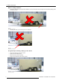
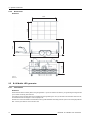
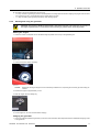
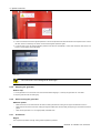
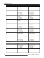
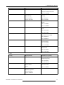
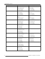
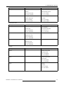
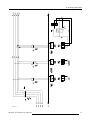
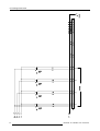
B-10 Mobile LED
Installation & maintenance manual
R9855510
R5976956/03
19/06/2007
Barco nv Events
Noordlaan 5, B-8520 Kuurne
Phone: +32 56.36.89.70
Fax: +32 56.36.88.24
E-mail: [email protected]
Visit us at the web: www.barco.com
Printed in Belgium
Changes
Barco provides this manual ’as is’ without warranty of any kind, either expressed or implied, including but not limited to the implied warranties or merchantability and fitness for a particular purpose. Barco may make improvements and/or changes to the product(s) and/or the
program(s) described in this publication at any time without notice.
This publication could contain technical inaccuracies or typographical errors. Changes are periodically made to the information in this
publication; these changes are incorporated in new editions of this publication.
Copyright ©
All rights reserved. No part of this document may be copied, reproduced or translated. It shall not otherwise be recorded, transmitted or
stored in a retrieval system without the prior written consent of Barco.
Guarantee and Compensation
Barco provides a guarantee relating to perfect manufacturing as part of the legally stipulated terms of guarantee. On receipt, the purchaser
must immediately inspect all delivered goods for damage incurred during transport, as well as for material and manufacturing faults Barco
must be informed immediately in writing of any complaints.
The period of guarantee begins on the date of transfer of risks, in the case of special systems and software on the date of commissioning,
at latest 30 days after the transfer of risks. In the event of justified notice of complaint, Barco can repair the fault or provide a replacement
at its own discretion within an appropriate period. If this measure proves to be impossible or unsuccessful, the purchaser can demand a
reduction in the purchase price or cancellation of the contract. All other claims, in particular those relating to compensation for direct or
indirect damage, and also damage attributed to the operation of software as well as to other services provided by Barco, being a component
of the system or independent service, will be deemed invalid provided the damage is not proven to be attributed to the absence of properties
guaranteed in writing or due to the intent or gross negligence or part of Barco.
If the purchaser or a third party carries out modifications or repairs on goods delivered by Barco, or if the goods are handled incorrectly,
in particular if the systems are commissioned operated incorrectly or if, after the transfer of risks, the goods are subject to influences not
agreed upon in the contract, all guarantee claims of the purchaser will be rendered invalid. Not included in the guarantee coverage are
system failures which are attributed to programs or special electronic circuitry provided by the purchaser, e.g. interfaces. Normal wear as
well as normal maintenance are not subject to the guarantee provided by Barco either.
The environmental conditions as well as the servicing and maintenance regulations specified in the this manual must be complied with by
the customer.
Trademarks
Brand and product names mentioned in this manual may be trademarks, registered trademarks or copyrights of their respective holders.
All brand and product names mentioned in this manual serve as comments or examples and are not to be understood as advertising for
the products or their manufactures.
Table of contents
TABLE OF CONTENTS
1. Safety instructions . . . . . . . . . . . . . . . . . . . . . . . . . . . . . . . . . . . . . . . . . . . . . . . . . . . . . . . . . . . . . . . . . . . . . . . . . . . . . . . . . . . . . . . . . . . . . . . . 3
1.1
1.2
1.3
1.4
1.5
1.6
1.7
General instructions . . . . . . . . . . . . . . . . . . . . . . . . . . . . . . . . . . . . . . . . . . . . . . . . . . . . . . . . . . . . . . . . . . . . . . . . . . . . . . . . . . . . . . . . . . . . . . . . . . . . . . . . . . . . . . . . .
Important Safety instructions . . . . . . . . . . . . . . . . . . . . . . . . . . . . . . . . . . . . . . . . . . . . . . . . . . . . . . . . . . . . . . . . . . . . . . . . . . . . . . . . . . . . . . . . . . . . . . . . . . . . . . . .
Safety instructions for LED screen setup . . . . . . . . . . . . . . . . . . . . . . . . . . . . . . . . . . . . . . . . . . . . . . . . . . . . . . . . . . . . . . . . . . . . . . . . . . . . . . . . . . . . . . . . . . .
Safety instruction when driving the trailer. . . . . . . . . . . . . . . . . . . . . . . . . . . . . . . . . . . . . . . . . . . . . . . . . . . . . . . . . . . . . . . . . . . . . . . . . . . . . . . . . . . . . . . . . . .
Important Warnings. . . . . . . . . . . . . . . . . . . . . . . . . . . . . . . . . . . . . . . . . . . . . . . . . . . . . . . . . . . . . . . . . . . . . . . . . . . . . . . . . . . . . . . . . . . . . . . . . . . . . . . . . . . . . . . . . .
Specific warnings for diesel-fueled generator . . . . . . . . . . . . . . . . . . . . . . . . . . . . . . . . . . . . . . . . . . . . . . . . . . . . . . . . . . . . . . . . . . . . . . . . . . . . . . . . . . . . . .
Specific warning for the jockey wheel . . . . . . . . . . . . . . . . . . . . . . . . . . . . . . . . . . . . . . . . . . . . . . . . . . . . . . . . . . . . . . . . . . . . . . . . . . . . . . . . . . . . . . . . . . . . . .
3
4
4
4
5
5
5
2. System Overview . . . . . . . . . . . . . . . . . . . . . . . . . . . . . . . . . . . . . . . . . . . . . . . . . . . . . . . . . . . . . . . . . . . . . . . . . . . . . . . . . . . . . . . . . . . . . . . . . . 9
2.1
2.2
Introduction . . . . . . . . . . . . . . . . . . . . . . . . . . . . . . . . . . . . . . . . . . . . . . . . . . . . . . . . . . . . . . . . . . . . . . . . . . . . . . . . . . . . . . . . . . . . . . . . . . . . . . . . . . . . . . . . . . . . . . . . . . 9
B-10 Mobile LED tiles . . . . . . . . . . . . . . . . . . . . . . . . . . . . . . . . . . . . . . . . . . . . . . . . . . . . . . . . . . . . . . . . . . . . . . . . . . . . . . . . . . . . . . . . . . . . . . . . . . . . . . . . . . . . . . . 9
2.2.1 Functionality. . . . . . . . . . . . . . . . . . . . . . . . . . . . . . . . . . . . . . . . . . . . . . . . . . . . . . . . . . . . . . . . . . . . . . . . . . . . . . . . . . . . . . . . . . . . . . . . . . . . . . . . . . . . . . . . . . . 9
2.2.2 SLite 10 XP specifications . . . . . . . . . . . . . . . . . . . . . . . . . . . . . . . . . . . . . . . . . . . . . . . . . . . . . . . . . . . . . . . . . . . . . . . . . . . . . . . . . . . . . . . . . . . . . . . . . . . . 10
2.2.3 Dimensions SLite XP tile . . . . . . . . . . . . . . . . . . . . . . . . . . . . . . . . . . . . . . . . . . . . . . . . . . . . . . . . . . . . . . . . . . . . . . . . . . . . . . . . . . . . . . . . . . . . . . . . . . . . . 11
2.2.4 SLite tile input/output ports . . . . . . . . . . . . . . . . . . . . . . . . . . . . . . . . . . . . . . . . . . . . . . . . . . . . . . . . . . . . . . . . . . . . . . . . . . . . . . . . . . . . . . . . . . . . . . . . . . . 11
2.3 LED Pro . . . . . . . . . . . . . . . . . . . . . . . . . . . . . . . . . . . . . . . . . . . . . . . . . . . . . . . . . . . . . . . . . . . . . . . . . . . . . . . . . . . . . . . . . . . . . . . . . . . . . . . . . . . . . . . . . . . . . . . . . . . . . . 12
2.3.1 Functionality. . . . . . . . . . . . . . . . . . . . . . . . . . . . . . . . . . . . . . . . . . . . . . . . . . . . . . . . . . . . . . . . . . . . . . . . . . . . . . . . . . . . . . . . . . . . . . . . . . . . . . . . . . . . . . . . . . . 12
2.3.2 LED-PRo features . . . . . . . . . . . . . . . . . . . . . . . . . . . . . . . . . . . . . . . . . . . . . . . . . . . . . . . . . . . . . . . . . . . . . . . . . . . . . . . . . . . . . . . . . . . . . . . . . . . . . . . . . . . . 13
2.4 B-10 Mobile LED trailer. . . . . . . . . . . . . . . . . . . . . . . . . . . . . . . . . . . . . . . . . . . . . . . . . . . . . . . . . . . . . . . . . . . . . . . . . . . . . . . . . . . . . . . . . . . . . . . . . . . . . . . . . . . . . . 13
2.4.1 Functionality. . . . . . . . . . . . . . . . . . . . . . . . . . . . . . . . . . . . . . . . . . . . . . . . . . . . . . . . . . . . . . . . . . . . . . . . . . . . . . . . . . . . . . . . . . . . . . . . . . . . . . . . . . . . . . . . . . . 13
2.4.2 Dimensions. . . . . . . . . . . . . . . . . . . . . . . . . . . . . . . . . . . . . . . . . . . . . . . . . . . . . . . . . . . . . . . . . . . . . . . . . . . . . . . . . . . . . . . . . . . . . . . . . . . . . . . . . . . . . . . . . . . . 14
2.5 B-10 Mobile LED generator . . . . . . . . . . . . . . . . . . . . . . . . . . . . . . . . . . . . . . . . . . . . . . . . . . . . . . . . . . . . . . . . . . . . . . . . . . . . . . . . . . . . . . . . . . . . . . . . . . . . . . . . . 14
2.5.1 Introduction. . . . . . . . . . . . . . . . . . . . . . . . . . . . . . . . . . . . . . . . . . . . . . . . . . . . . . . . . . . . . . . . . . . . . . . . . . . . . . . . . . . . . . . . . . . . . . . . . . . . . . . . . . . . . . . . . . . . 14
2.5.2 Components. . . . . . . . . . . . . . . . . . . . . . . . . . . . . . . . . . . . . . . . . . . . . . . . . . . . . . . . . . . . . . . . . . . . . . . . . . . . . . . . . . . . . . . . . . . . . . . . . . . . . . . . . . . . . . . . . . . 15
2.5.3 Control panel . . . . . . . . . . . . . . . . . . . . . . . . . . . . . . . . . . . . . . . . . . . . . . . . . . . . . . . . . . . . . . . . . . . . . . . . . . . . . . . . . . . . . . . . . . . . . . . . . . . . . . . . . . . . . . . . . . 16
2.5.4 Starting and using the generator . . . . . . . . . . . . . . . . . . . . . . . . . . . . . . . . . . . . . . . . . . . . . . . . . . . . . . . . . . . . . . . . . . . . . . . . . . . . . . . . . . . . . . . . . . . . . 17
2.5.5 Stopping the generator . . . . . . . . . . . . . . . . . . . . . . . . . . . . . . . . . . . . . . . . . . . . . . . . . . . . . . . . . . . . . . . . . . . . . . . . . . . . . . . . . . . . . . . . . . . . . . . . . . . . . . . 18
2.5.6 About cooling the generator . . . . . . . . . . . . . . . . . . . . . . . . . . . . . . . . . . . . . . . . . . . . . . . . . . . . . . . . . . . . . . . . . . . . . . . . . . . . . . . . . . . . . . . . . . . . . . . . . . 18
2.5.7 Protections . . . . . . . . . . . . . . . . . . . . . . . . . . . . . . . . . . . . . . . . . . . . . . . . . . . . . . . . . . . . . . . . . . . . . . . . . . . . . . . . . . . . . . . . . . . . . . . . . . . . . . . . . . . . . . . . . . . . 18
2.5.8 Maintenance . . . . . . . . . . . . . . . . . . . . . . . . . . . . . . . . . . . . . . . . . . . . . . . . . . . . . . . . . . . . . . . . . . . . . . . . . . . . . . . . . . . . . . . . . . . . . . . . . . . . . . . . . . . . . . . . . . 19
2.5.9 Safety for the user . . . . . . . . . . . . . . . . . . . . . . . . . . . . . . . . . . . . . . . . . . . . . . . . . . . . . . . . . . . . . . . . . . . . . . . . . . . . . . . . . . . . . . . . . . . . . . . . . . . . . . . . . . . . 19
2.5.10 Spare parts generator . . . . . . . . . . . . . . . . . . . . . . . . . . . . . . . . . . . . . . . . . . . . . . . . . . . . . . . . . . . . . . . . . . . . . . . . . . . . . . . . . . . . . . . . . . . . . . . . . . . . . . . . 19
3. Setup of the B-10 Mobile LED . . . . . . . . . . . . . . . . . . . . . . . . . . . . . . . . . . . . . . . . . . . . . . . . . . . . . . . . . . . . . . . . . . . . . . . . . . . . . . . . . . . 21
3.1
3.2
3.3
3.4
3.5
3.6
Installation of the B-10 Mobile LED . . . . . . . . . . . . . . . . . . . . . . . . . . . . . . . . . . . . . . . . . . . . . . . . . . . . . . . . . . . . . . . . . . . . . . . . . . . . . . . . . . . . . . . . . . . . . . . . . 21
Powering the B-10 Mobile LED . . . . . . . . . . . . . . . . . . . . . . . . . . . . . . . . . . . . . . . . . . . . . . . . . . . . . . . . . . . . . . . . . . . . . . . . . . . . . . . . . . . . . . . . . . . . . . . . . . . . . 21
Extending the LED display . . . . . . . . . . . . . . . . . . . . . . . . . . . . . . . . . . . . . . . . . . . . . . . . . . . . . . . . . . . . . . . . . . . . . . . . . . . . . . . . . . . . . . . . . . . . . . . . . . . . . . . . . . 22
Rotating the LED display . . . . . . . . . . . . . . . . . . . . . . . . . . . . . . . . . . . . . . . . . . . . . . . . . . . . . . . . . . . . . . . . . . . . . . . . . . . . . . . . . . . . . . . . . . . . . . . . . . . . . . . . . . . . 24
Move down the LED Display . . . . . . . . . . . . . . . . . . . . . . . . . . . . . . . . . . . . . . . . . . . . . . . . . . . . . . . . . . . . . . . . . . . . . . . . . . . . . . . . . . . . . . . . . . . . . . . . . . . . . . . . 24
Preparing for departure. . . . . . . . . . . . . . . . . . . . . . . . . . . . . . . . . . . . . . . . . . . . . . . . . . . . . . . . . . . . . . . . . . . . . . . . . . . . . . . . . . . . . . . . . . . . . . . . . . . . . . . . . . . . . . 25
4. Maintenance, Service . . . . . . . . . . . . . . . . . . . . . . . . . . . . . . . . . . . . . . . . . . . . . . . . . . . . . . . . . . . . . . . . . . . . . . . . . . . . . . . . . . . . . . . . . . . . . 27
4.1
4.2
Service and maintenance table . . . . . . . . . . . . . . . . . . . . . . . . . . . . . . . . . . . . . . . . . . . . . . . . . . . . . . . . . . . . . . . . . . . . . . . . . . . . . . . . . . . . . . . . . . . . . . . . . . . . . 27
Service and Maintenance of the Generator . . . . . . . . . . . . . . . . . . . . . . . . . . . . . . . . . . . . . . . . . . . . . . . . . . . . . . . . . . . . . . . . . . . . . . . . . . . . . . . . . . . . . . . . 29
A. Drawings B10 trailer. . . . . . . . . . . . . . . . . . . . . . . . . . . . . . . . . . . . . . . . . . . . . . . . . . . . . . . . . . . . . . . . . . . . . . . . . . . . . . . . . . . . . . . . . . . . . . . . 37
A.1
Electrical drawings. . . . . . . . . . . . . . . . . . . . . . . . . . . . . . . . . . . . . . . . . . . . . . . . . . . . . . . . . . . . . . . . . . . . . . . . . . . . . . . . . . . . . . . . . . . . . . . . . . . . . . . . . . . . . . . . . . . 37
R5976956 B-10 MOBILE LED 19/06/2007
1
Table of contents
2
R5976956 B-10 MOBILE LED 19/06/2007
1. Safety instructions
1. SAFETY INSTRUCTIONS
Overview
1.1
•
General instructions
•
Important Safety instructions
•
Safety instructions for LED screen setup
•
Safety instruction when driving the trailer
•
Important Warnings
•
Specific warnings for diesel-fueled generator
•
Specific warning for the jockey wheel
General instructions
Caution
Setup of the B-10 Mobile LED should be performed only after you are thoroughly familiar with all of the proper safety checks and
setup instructions. To do otherwise increases the risk of hazards and injury to the user.
Do not modify and/or replicate any component. Barco uses specific materials and manufacturing processes in order to achieve
mechanical strength of the trailer and hydraulic mast. Consult Barco for assistance with custom applications.
Always follow Barco setup instructions. Contact Barco if you should have any question regarding the safety of an application.
The manufacturer assumes no liability for incorrect, inadequate, irresponsible or unsafe use of systems.
Product care
Barco products must be used in a manner consistent with their design and inspected on a routine basis for security, wear, deformation, corrosion and any other circumstances that may affect the proper working of the B-10 Mobile LED.
Barco recommends inspections at regular intervals for the B-10 Mobile LED. If a part of the B-10 Mobile LED is found to have
damage, it must be removed for service or replaced immediately.
Under no circumstances are Barco parts repairable by anyone other than Barco.
Owner’s record
The part number and serial number are printed on a labels which are stuck on the respective parts. Record these numbers in the
spaces provided below. Refer to them whenever you call upon your Barco custom service engineer regarding this product.
Name
R5976956 B-10 MOBILE LED 19/06/2007
Part number
Serial number
Supplier
3
1. Safety instructions
1.2
Important Safety instructions
Instructions:
•
Read these instructions.
•
Keep these instructions.
•
Heed all warnings.
•
Follow all instructions.
•
IMPORTANT, plug holder clamps must be locked firmly on all controller units and power boxes to prevent the possible ingress
of fluids or solid particles. Replace damaged clamps immediately.
•
Clean only with materials or chemicals that are inert, nonabrasive, noncorrosive and non-marking. Consult the manufacturer
for further advice should any doubts exist regarding any cleaning procedure.
•
Do not block ventilation openings. Install in accordance with the manufacturers instructions.
•
Do not defeat the safety purpose of the polarized or grounding type plugs/sockets. If the provided sockets / plugs are damaged
then replacement of the defective parts must be undertaken immediately.
•
Protect the power/data cords from being walked on or pinched particularly at plugs, convenience receptacles, and the point
where they exit from the apparatus. Replace damaged power/data cords immediately.
•
Only use attachments/accessories specified by the manufacturer.
•
Disconnect the power to this apparatus during lightning storms or provide suitable additional lightning protection. Unplug this
apparatus when unused for long period of time.
•
Refer all servicing to qualified service technicians/personnel. Servicing is required when the B-10 Mobile LED has been damaged in any way, such as hydraulic mast or generator is damaged, the B-10 Mobile LED does not operate normally.
•
Use only with systems or peripherals specified by the manufacturer, or sold with the apparatus. Use caution during transporting
to avoid damage by possible tipping.
•
Do not make use of the B-10 Mobile LED to climb on the display.
•
Do not place a ladder against the display to access the tiles or for other purposes.
•
Do not move the trailer when the B-10 Mobile LED display is in the air.
•
Do not walk on the roof of the trailer as it has not been designed and reinforced for this purpose.
1.3
Safety instructions for LED screen setup
Overview
•
Only trained people are allowed to set up the LED screen
•
No people are allowed around or in the trailer during the setup process of the LED Screen.
•
Always put the trailer legs out before lifting the screen.
•
Always lock the turntable.
•
Always use mechanical locks to lock the turntable.
•
Maximum wind force = 8 Beaufort. When the wind force is higher than the maximum allowed wind force, bring the screen down
•
Always place the safety pins in the mast.
1.4
Safety instruction when driving the trailer
Overview
4
•
Always stick to the local traffic rules.
•
Always respect the local motor vehicle inspection for trailer and car.
•
Set draw-bar till trailer level.
•
Tires pressure: 3,75 bar
•
Max weight under coupling: 150 kg
•
Maximum driving speed is 90 km/h. Slow down in the bends.
R5976956 B-10 MOBILE LED 19/06/2007
1. Safety instructions
1.5
Important Warnings
Important warnings
•
High leakage current:
The combination of multiple tiles in an installation results in increased levels of leakage current. In order to avoid risk of electric
shock due to high leakage current, proper grounding of the installation is required.
•
Flammable materials:
Keep flammable materials away from theB-10 Mobile LED generator. A lot of energy is transferred into heat. The installation
should be such that the amount of air flow required for safe operation of the equipment is not compromised. Proper ventilation
must be provided.
•
Mains cords:
The power cords delivered with this system have special properties for safety. They are not user serviceable. If the power cords
are damaged, replace only with new ones. Never try to repair a power cord.
1.6
Specific warnings for diesel-fueled generator
Check before operating the engine
•
If the engine is malfunctioning DO NOT operates until repairs are made.
•
Be sure all guards and shields are in place before operating the engine. Replace any that are damaged or missing.
•
DO NOT start the engine by shorting across starter terminals.
Handling of fuel and lubricants
•
Always stop the engine before refueling or lubricating.
•
DO NOT smoke or allow flames or sparks in your working area. Fuel is extremely flammable and explosive.
•
Never store flammable liquids in the engine compartment.
•
Refuel at a well-ventilated and open place. If fuel or lubricants spill, clean up immediately and properly dispose of.
•
DO NOT mix gasoline or alcohol with diesel fuel. The mixture can cause a fire.
Fire prevention
•
To avoid a fire, be alert for leaks of flammables from hoses and lines. Be sure to check for leaks from hoses and pipes, such
as fuel and hydraulic by following the maintenance check list.
•
To avoid a fire, do not short across power cables and wires. Check to see that all power cables and wires are in good condition.
Keep all power connections clean. Bare wire or frayed insulation can cause a dangerous electrical shock and personal injury.
Cautions against burns and battery explosion
•
To avoid burns, be alert for hot components during operation and just after the engine has been shut off. Such as the muffler,
muffler cover, radiator, piping, engine body, coolants, engine oil, etc.
Conducting safety checks and maintenance
1.7
•
Maintenance of the generator is only to be performed by a specialized service technician.
•
When performing safety checks or engine service, be sure the engine is level and well supported. Use approved stands designed for this type of service.
•
Check or conduct maintenance after the engine, radiator, muffler, or muffler cover has cooled off completely.
•
When service is performed with two or more people present, take care to perform all work safely. Be aware of their location
especially when starting the engine.
Specific warning for the jockey wheel
About the load
A jockey wheel has a maximum allowed load of 250 Kg. When the load is exceeded, the jockey wheel and the folding system get
damaged.
R5976956 B-10 MOBILE LED 19/06/2007
5
1. Safety instructions
What is a faulty operation
•
Levelling the trailer by first placing the rear stabilizers. This way almost the half of the weight of the total trailer (1800 Kg) rests
on the jockey wheel.
Image 1-1
Wrong way to level trailer
•
Unhitching the trailer by first retracting the front stabilizers.
Image 1-2
Wrong way to level trailor
The good way of working, setting up the vehicle
•
Unhitch the vehicle from the puller vehicle.
•
Extend the front stabilizers first.
•
Retract the jockey wheel completely.
•
Extend the rear stabilizers and level the vehicle.
Image 1-3
Correct way to setup
6
R5976956 B-10 MOBILE LED 19/06/2007
1. Safety instructions
The good way of working, building off the vehicle
•
Retract the rear stabilizers first and then the front stabilizers till none of them touch the ground.
•
Turn the jockey wheel downwards till the wheel touches the ground. Do not lift the trailer at the front side !
•
Bring the draw bar to the height of the ball coupling in such a way that the trailer has exactly the same height at the front and
at the rear.
•
Lift the draw bar a little with the jockey wheel and couple to the trailer.
R5976956 B-10 MOBILE LED 19/06/2007
7
1. Safety instructions
8
R5976956 B-10 MOBILE LED 19/06/2007
2. System Overview
2. SYSTEM OVERVIEW
Overview
2.1
•
Introduction
•
B-10 Mobile LED tiles
•
LED Pro
•
B-10 Mobile LED trailer
•
B-10 Mobile LED generator
Introduction
Overview
The B-10 Mobile LED is a mobile outdoor LED display solution. The LED-wall comes in a trailer that can be pulled by a vehicle with
a 3500 kg towing capacity. All electronics are stored properly and compact when traveling.
Image 2-1
Trailer side view
LED tiles used in the B-10 Mobile LED are SLite10 XP tiles with pixel pitch of 10mm, in a 4x4 configuration (9.6m2 - 103.3ft2) and
typically designed for outdoor use.
When arriving on the event location, the B-10 Mobile LED can easily be set up. The wall itself slides out of the trailer by means of a
hydraulic system. There is no need for trusses and structures to be set up. The screen can be turned around 360 degrees, allowing
you to adjust the display to face the audience.
The B-10 Mobile LED contains a diesel-fueled generator. No external power supply is required, and it comes with a Barco LED-PRO
or D320 Digitizer for high quality image processing.
The following topic enumerates all different components of a B-10 Mobile LED solution and describe their
functionality in the system. FOR MORE DETAILED INFORMATION ON THESE COMPONENTS PLEASE REFER
TO THEIR RESPECTIVE MANUAL.
2.2
2.2.1
B-10 Mobile LED tiles
Functionality
Overview
The B-10 Mobile LED is with outdoor SLite 10 XP tiles. The SLite XP can overlay video and data sources in their native quality.
A unique video processing feature enables the creation of a visual resolution quasi double the physical resolution defined by the
cluster of LED’s spread on the surface of the display. The SLite XP is an IP65 rating rugged module.
R5976956 B-10 MOBILE LED 19/06/2007
9
2. System Overview
Image 2-2
All tiles are connected in series via a data path. Each tile picks out a part of the video information of the data stream on the data
path and processes this information for displaying on its LED’s.
2.2.2
SLite 10 XP specifications
Specifications
Visual Resolution
10.18 mm
Physical Resolution
20.36 mm
Brightness
6500 NIT
Calibrated Brightness
5500 NIT (calibrated at 6500°K)
LED configuration
2R, 1G, 1B
LED density
9646/m² (896/ft²)
5808/panel (88 x 66)
Hor. viewing angle
120°
Vert. viewing angle
60°
Contrast ratio
2000:1 at 200 lux
Lifetime
50 000 h (full white - half brightness)
100 000 h (typical use)
Power consumption
maximum: 680 W / Tile
average: 170 W / Tile
Weight / Tile
40 kg (88.2 lbs) excluding structure
Processing
14 bit
Colors
4.4 trillion
Refresh rate
> 2000 Hz (PAL / NTSC)
Ruggedness
IP 65
Temperature range
operating: -20 - 40°C (-4 - 104°F)
storage: -20 - 60°C (-4 - 140°F)
Humidity
operating: 10 - 99%
storage: 10 - 99%
10
R5976956 B-10 MOBILE LED 19/06/2007
2. System Overview
D320 input compatibility
S-Video, Composite, YUV, RGB, SDI, HDSDI, Data DVI up to UXGA
Certifications
ETL, CE, CEBEC, TUV, FCC class A
Tile dimensions
width: 896mm (35.3")
height: 672mm (26.5")
depth: 248mm (9.8")
R9004170
Order Information
2.2.3
Dimensions SLite XP tile
SLite XP tile dimensions
248
896
672
180
560
710
Image 2-3
Dimensions given in millimeters.
2.2.4
SLite tile input/output ports
Location input/output ports
There are four connection ports on the back of each SLite tile. Two power ports and two data ports. All ports are waterproof and
located on the ’Connection module’.
The data ports consist of two waterproof MDR connectors at the right side of the connection module. The data is coming in on the
lower right MDR connector of the connection module. The upper right MDR connector is used to loop the data through.
The power ports consist in one waterproof C19 connector in the lower left corner and one waterproof C20 connector in the upper
left corner of the connection module, respectively used for power input and power output.
R5976956 B-10 MOBILE LED 19/06/2007
11
2. System Overview
A
E
C
A
B
D
Image 2-4
SLite input/output ports.
A
B
C
D
E
Image 2-5
A
Plug holder clamp.
Connection module.
Power input port.
Power output port.
Data input port.
Data output port.
CAUTION: The SLite input/output ports can only be used in conjunction with Barco’s outdoor cables for LEDwalls. Do not use any other cables then those specified.
CAUTION: Dummy plugs must be placed on unused connection ports of the connection module and all plug
holder clamps must be locked firmly.
2.3
LED Pro
2.3.1
Functionality
Overview
The Barco LED-PRO TM is a powerful all-in-one signal processor that accepts a wide range of video input signals and processes
them to drive Barco LED Displays. The LED-PRO TM allows you to scale visual sources, mix and match them in any way while still
maintaining a high quality picture. The unit is a high performance digital video scaler, scan converter, standards converter, switcher
and transcoder in one. The LED-PRO TM is the ideal solution for converting RGB, HDTV, component, S-Video, composite (NTSC,
PAL and SECAM), SDI, DVI, and HD-SDI for use with the B-10 Mobile LED.
The LED-PRO TM has an advanced feature set that includes:
12
•
universal inputs
•
aspect ratio conversion
•
memory presets
•
test patterns
•
Lock to Source
•
picture adjustments
•
motion adaptive de-interlacing
•
3:2 and 2:2 pull down detection
R5976956 B-10 MOBILE LED 19/06/2007
2. System Overview
Image 2-6
LEDPRo
2.3.2
LED-PRo features
Overview
•
•
•
•
2.4
2.4.1
Three universal inputs accept RGBHV/RGBCs/RGsB computer video, component video (STD or HDTV), SVideo, or composite
video with loop-through
SD SDI/HD-SDI input.
DVI-I connectors support both universal analog and DVI input with loop-through.
DVI output connector for Barco LED Display interface.
•
Input Video detection and Auto-acquisition. LED-PRO TM will auto detect and match input video to stored formats or user
configurations.
•
Aspect ratio conversion and adjustments
•
Pan and zoom
•
Freeze
•
10-Bit processing
•
De-interlacing modes: Motion Adaptive and Field to Frame
•
3:2 pulldown detection for NTSC and 2:2 film detection for PAL video sources
•
Decodes NTSC, PAL, and SECAM
•
Ethernet connector for real-time control
•
Vertical lock (Lock to Source) eliminates image tears and other artifacts in scaled motion video by eliminating frame rate conversion
•
64 independent input configuration memory presets
•
Motion adaptive de-interlacing for HDTV inputs
•
Low Video Delay
B-10 Mobile LED trailer
Functionality
Overview
The B-10 Mobile LED is a mobile outdoor LED display solution. The LED-wall comes in a trailer that can be pulled by a vehicle with
a 3500 kg towing capacity. All electronics are stored properly and compact when traveling. When arriving to the event location The
LED-wall can easily be put out of the trailer by means of a hydraulic mast and simple lever-control. There is no need for trusses and
structures to be set up. The screen can then be turned around 360 degrees, allowing you to adjust the display to face the audience.
R5976956 B-10 MOBILE LED 19/06/2007
13
2. System Overview
2.4.2
Dimensions
Overview
2112
2500
2688
3584
2385
4240
Image 2-7
Dimensions
2.5
2.5.1
B-10 Mobile LED generator
Introduction
Overview
Please read this section carefully before using the generator. If you act as stated in this section, your generating set will guarantee
you a smooth functioning time after time.
First read the engine and alternator manual supplied with each generating set. Here you will find more information about the use,
the maintenance and the dangers in case of improper use.
All data in this manual are based on the standard version type EPS183TDE. Generating sets with options can have slightly different
data. Contact your dealer for more info about this.
14
R5976956 B-10 MOBILE LED 19/06/2007
2. System Overview
2.5.2
Components
Overview
•
Type: EPS183TDE
•
Power: 3 x 400V : 18kVA, 1 x 230V : 6kVA
•
Alternator: Leroy Somer LSA37M8 with AVR (brush less)
•
Engine: KUBOTA D1105, 3-cylinder, 1123cm³, 3000 rpm, water-cooled
•
Content of fuel tank: 63 liters
•
Fuel type: diesel
•
Dimensions: 150 x 64 x 90 cm
•
Weight: 425 kg
•
Noise level: LwA 93
Image 2-8
Control panel generator
Please refer to the Diesel Motor and Alternator manual for more detail on these components.
The main components of the generating set are: the water-cooled KUBOTA diesel engine 3000rpm for EPS183TDE, the alternator,
the control panel, the silenced canopy and the chassis.
Engine and alternator specifications can be found in the engine and alternator manual supplied with each generating set.
The chassis of the generator serves as fuel tank and contains the fuel filler cap, the mechanic fuel level meter, the fuel drain cap (for
cleaning of fuel tank), 4 fixation holes (for fixed mounting of the genset), the battery support and the fixing support for the (manual)
oil drain pump.
The silenced canopy of the generator contains: one central lifting eye, 2 plastic inspection hatches in the top cover for the radiator
filler cap and oil filler cap, two doors with lock (for normal maintenance), a control panel, an inspection hatch for the battery, a cold
air intake grid, a hot air exhaust grid.
The exhaust goes through the hot air exhaust grid. The whole of this is mounted on 4 anti vibration engine suspensions ( Type
RAEM 350 A ) to prevent vibrations to be transferred to the trailer and permit a more comfortable use of the machinery.
R5976956 B-10 MOBILE LED 19/06/2007
15
2. System Overview
2.5.3
Control panel
Description
Image 2-9
Control panel
The control panel of the EPS8DE consists of:
•
16
Starting key (off / on / glow / start)
•
Pilot lamp green (contact on / off), lamp lights up when contact on
•
Pilot lamp red (charging current battery), lamp lights up when battery is not being charged
•
Hours counter
•
1 fuse ( 2A ) hours counter
•
Measuring unit , 3-fases for voltage, frequency en current
•
Voltage presence indicator ( 3-fases )
•
3 fuses ( 2 A ) for mentioned above
•
Main breaker 25A 4p
•
Earth leakage protection 40A 4p,300mA, class A
•
1 x breaker 16A 2p/C/10kA (electronics)
•
1 x breaker 16A 2p/C/10kA (hydraulics )
•
1 x breaker 10A 2p/C/10kA (lights)
•
4 x breaker 16A 2p/C/10kA (video screen)
•
1 x socket CE 16 (electronics)
•
1 x socket CE 16 (hydraulics)
•
1 x socket CE 16 (lights)
•
1 x Tour mate multiconnector female chassis ( supply video )
•
Earth connection point
•
Emergency stop
•
32A CEE free socket (power from generator set)
•
32A CEE plug panel mount (supply to power distribution box) possibility to provide power from auxiliary device (grid)
R5976956 B-10 MOBILE LED 19/06/2007
2. System Overview
On the inside of the control panel there can be found:
2.5.4
•
2 x relay 12V/30A for guarding oil pressure and temperature of cooling liquid with aid of a stopping coil (Engine shuts off when
the oil pressure is low or the temperature of the cooling liquid is to high).
•
1 x relay 12V/30A by-pass guards (oil pressure) when starting engine.
Starting and using the generator
CAUTION: The generator 183TDE is equipped with a 12V electric fuel pump. This pump may not “run dry”. If
the engine stops because it is out of fuel, turn the contact key to position “OFF” as fast as possible.
Starting the engine
1. Check the oil level. Oil dipstick can be reached through the plastic cover on top of the generating set
Image 2-10
Oil level check
2. Check the fuel level, add if necessary .
Image 2-11
Fuel check
Caution:
Adding fuel with engine stopped and in a sufficiently ventilated room, respecting the necessary personal safety precautions.
3. Preheat the engine for approximately 10 sec.
4. Start the engine with the starting key.
Image 2-12
5. Let the engine run for a few minutes before charging.
Charging the generator
1. On the type indication plate of the generator you can find more information about the power/maximum admissible charging current
of the generator.
R5976956 B-10 MOBILE LED 19/06/2007
17
2. System Overview
Image 2-13
Identification
2. In case of overload, the thermal-magnetic protection in the control panel shall be switched off after a short period of time. Check
the load, reduce it if necessary and switch on the thermal-magnetic protection again.
3. In case of short-circuit, the thermal-magnetic protection will switch off immediately! Check what caused the short-circuit and
switch on the protection again afterwards.
Image 2-14
Main breaker
CAUTION: Never let the diesel engine run for longer periods (> 30 min) without charge or small loads (< 15%).
This could result in severe damage to the diesel engine.
2.5.5
Stopping the generator
How to stop
1. Let the generator run at no load for a few more minutes before stopping it. In this way the generator can "cool down".
2. Stop the generator with the starting key.
2.5.6
About cooling the generator
Attention points
2.5.7
•
Make sure there are no obstructions at the fresh air intake grid where the cooling air for engine and alternator comes in.
•
Make sure the hot air that comes from cooling the engine and alternator can leave easily through the grid, as well as the exhaust
gases.
•
Never let the generator run in an inappropriately ventilated room!
Protections
Engine
Low oil pressure protection and high cooling water temperature protection.
18
R5976956 B-10 MOBILE LED 19/06/2007
2. System Overview
Image 2-15
Alternator
Thermal-magnetic protection and earth leakage protection (with earth pin).
Image 2-16
2.5.8
Maintenance
Overview
All maintenance points (air filter, oil drain pump, oil filler cap, oil filter, fuel filters, radiator filler cap) are easily accessible. For normal
maintenance activities, check the engine manual.
For engine or alternator failure, consult a local dealer. For a list of service center, see "Service and Maintenance of the Generator
", page 29.
2.5.9
Safety for the user
Overview
The standard versions of these generators are equipped with an earth leakage protection and a thermal-magnetic protection, following the IN-S electrical scheme. For connection of charges of class 1 (charges with earth) and charges of class 2 (charges with
double insulation, to be recognized by the “double square” pictograph on the appliance) there are no restrictions concerning the
number of charges connected at the same time. Respect the minimum square (mm²) and maximum length of the extension cables
(to assure the correct switching off of the thermal-magnetic protection in case of short-circuit).
2.5.10 Spare parts generator
Overview
Nr
Description
Ordering reference
Euro power
Ordering reference
Fleedguard
Ordering reference
Kubota
1
Oil filter D1105/V1505
398211105
LF 3776
1627132092
R5976956 B-10 MOBILE LED 19/06/2007
19
2. System Overview
20
2
Fuel filter D1105/V1505
398111105
FF 5226
1522143080
3
In line filter D1105/V1505
130000016
FF 149
128143012
4
Air filter cartridge1105/V1505
398011105
AF 4939
1574111083
5
V – belt D1105/V1505
A130
6
Gasket valve cover D1105 BG2/EBB
A11105001
7
Battery 45Ah 12 V ( DIN 54577)
170000003
8
Injectors
16032-5300-0
9
Radiator assembly
10
Charging generator
11
AVR ( electronic )
200990099
12
Anti vibration support ( A puffer
motor ) 60/60
120000060
13
Anti vibration support ( A puffer
motor ) 75/55
12000075
14
Anti vibration support RAEM350
RA350EM
R5976956 B-10 MOBILE LED 19/06/2007
3. Setup of the B-10 Mobile LED
3. SETUP OF THE B-10 MOBILE LED
Overview
•
Installation of the B-10 Mobile LED
•
Powering the B-10 Mobile LED
•
Extending the LED display
•
Rotating the LED display
•
Move down the LED Display
•
Preparing for departure
3.1
Installation of the B-10 Mobile LED
Useful tools
In order to set up the B-10 Mobile LED more easily the following tools may be useful to purchase:
•
A level to verify the flat position of the trailer
•
A drill to position the 4 outriggers and fasten the 2 halves LED display parts together (4 bolts)
How to install?
1. Place the trailer on a flat and hard ground.
2. Unhitch the trailer from the ball hitch. For this purpose, you may need to use the jockey wheel. After using the jockey wheel wind
it fully up to its initial (up) position.
Note: After using the jockey wheel wind it fully up to its initial (up) position.
Caution:
Only use the jockey wheel to engage and disengage the trailer on & from the towing hook. After usage, always wind
the jockey wheel fully up to avoid damages on the jockey wheel.
Image 3-1
3. Trigger the brake system of the B-10 Mobile LED (back position)
4. Take the wooden plate (in the B-10 Mobile LED left at door entrance) and position them below the outriggers.
5. Start by extending the front stabilizer.
Tip:
If the stabilizers cannot reach the wooden plates, put additional wooden plates under the outriggers.
6. Retract the jockey wheel completely.
Caution: After using the jockey wheel wind it fully up to its initial (up) position. Only use the jockey wheel to engage and
disengage the trailer on or from the towing hook.
Caution:
A jockey wheel may have a maximum allowed load of 250 kg. Do not use the jockey wheel faulty as it can damage
the wheel and the folding system.
7. Extend the rear stabilizers.
8. Level the B-10 Mobile LED vehicle and try to position it as “flat” as possible in the length and the width. Use therefore a level
and adjust the stabilizers accordingly.
3.2
Powering the B-10 Mobile LED
How to power up?
1. Put the contact in the warm up position. After several seconds turn-on the generator with the contact key.
R5976956 B-10 MOBILE LED 19/06/2007
21
3. Setup of the B-10 Mobile LED
Image 3-2
Contact key and power cable of pump
2. After several seconds turn-on the generator with this contact key.
Caution: The generator of the B-10 Mobile LED needs to be well-ventilated. Therefore, the generator of the B-10 Mobile LED
is not indented to run for a long period of time with the roof closed. Once the generator is running, the screen needs
to be lifted immediately.
3. Insert the power cable of the hydraulic pump in the generator (Red-plug)
4. Connect the grounding conductor to a grounding rod or other acceptable earth grounding method.
3.3
Extending the LED display
Extending process
1. Open the air arrival to start the pump.
22
R5976956 B-10 MOBILE LED 19/06/2007
3. Setup of the B-10 Mobile LED
Image 3-3
Pump system
2. Push on the black button.
3. Lift the first halve of the LED-wall by using the lever
Lift this part of the display up till its 10 cm above the deck of the B-10 Mobile LED.
Fastening both display halves together
1. Release the 4 fasteners of the bottom display and pull it below the top display.
Image 3-4
2. Bring down the upper display and position the bolts in the holes.
Note: Do not bring down the display much than needed!
3. Fasten the 2 halve displays together by fastening the bolts.
4. Plug in the 4 power cables and data cable.
Extending the full display
1. Extend the display to its top position.
2. Place the safety pieces in the mast.
R5976956 B-10 MOBILE LED 19/06/2007
23
3. Setup of the B-10 Mobile LED
Image 3-5
Safety pieces
Caution:
Make sure the safety pins are placed in the mast. This is mandatory for security reason and to avoid that the mast
comes slightly down after closing the pump system.
3. Stop the pump system by closing the air arrival and switching off the pump.
4. Press the red button.
3.4
Rotating the LED display
How to rotate?
1. Rotate the display to the desired position.
2. Lock this position.
Image 3-6
Mechanical lock
3.5
Move down the LED Display
CAUTION:
Do not use the pump to bring down the display.
When bringing down the display too fast, oil can spill out of the hydraulic system. This is not a leak !
24
R5976956 B-10 MOBILE LED 19/06/2007
3. Setup of the B-10 Mobile LED
How to move down?
1.
Lift down the display till it’s on the bottom.
Note: Do not forget to take away the safety pieces from the mast.
Caution:
Watch out that cables are not under the display.
2. Open the pump system and lift up the display a little.
3. Close the pump.
4. De-fasten the 2 half display and unplug the power and data cables.
5. Push back the bottom half display and fasten it with the 4 fasteners.
6. Lift down the top half display till it is on the bottom.
3.6
Preparing for departure
Steps to be taken
1. Retract the rear stabilizers.
2. Retract the front stabilizers.
3. Turn the jockey wheel downwards till the wheel touches the ground.
Note: Do not lift the trailer at the front side.
4. Bring the tong of the trailer to the height of the ball hitch so that the trailer has exactly the same height at the front and at the rear.
5. Release the brake system of the B-10 Mobile LED trailer.
6. Lift up the tong of the trailer a little with the jockey wheel and hitch it to the ball hitch.
7. Place the wooden plate in the B-10 Mobile LED trailer.
8. Retract the jockey wheel completely.
Caution: Only use the jockey wheel to hitch and unhitch the trailer on & from the ball hitch. After usage, always wind the jockey
wheel fully up to avoid damages on the jockey wheel.
R5976956 B-10 MOBILE LED 19/06/2007
25
3. Setup of the B-10 Mobile LED
26
R5976956 B-10 MOBILE LED 19/06/2007
4. Maintenance, Service
4. MAINTENANCE, SERVICE
Overview
For maintenance, service and repair on the B-10 Mobile LED please consult qualified service technicians/personnel.
Servicing is required when the B-10 Mobile LED has been damaged in any way, such as hydraulic mast or generator is damaged,
the B-10 Mobile LED does not operate normally.
4.1
Service and maintenance table
Overview
Below a service and maintenance overview table. For more information on the different parts, consult the respective manuals.
Daily
C
L
500 km
T
Cl
C
L
Yearly
Quarterly
T
Cl
C
L
T
Cl
C
L
T
Cl
Trailer
Towbar
Attachment to front
transverse
Attachment to 1st axle
Height adjustable bracket
system
Umbilical cord
Jockey wheel
hitch coupling
inertial brake
system
Course when braking
(barking action)
Grease nipple
Braking distance
Brake grips
Hand brake
Axles
Wheel bolts
Bearing clearance
Control cable
Brake linings
Brakes
Tires
Pressure
Bearing surface
Pressure of replacement
tire
Wheel wrench available
Lights
back-, front-lights
plug
Light cable
R5976956 B-10 MOBILE LED 19/06/2007
27
4. Maintenance, Service
Daily
C
L
500 km
T
Cl
C
L
Yearly
Quarterly
T
Cl
C
L
T
Cl
C
L
T
Cl
Light cover
Outriggers
Functioning
Attachment
Frame
Transverse at side section
support for girders
girders of mast
Transverse at compressor
Splashguards
Trailor enclosure
Doors
Lock system (inside)
Functioning doors
Door frame
Functioning lock
Rubber of door frame
Door stops
Door hinges
Nails
Walls
surrounding frames
nails
attachment to main frame
inside wall paneling
wall control room
Roof
attachment to side frames
attachment to display grid
Floor
attachment
holes for water evacuation
Display system
Pump
leaks
oil level
lever
attachment to frame
Rotation system
lubricate
attachment bolts 2x
Mast
functioning
oil losses of main cylinder
28
R5976956 B-10 MOBILE LED 19/06/2007
4. Maintenance, Service
Daily
C
L
500 km
T
Cl
C
L
Yearly
Quarterly
T
Cl
C
L
T
Cl
C
L
T
Cl
cylinder flexible
attachment to grid
Generator
general
motor
alternator
oil
gas - diesel
exhausts
fixing
state
C = Control
L = Lubricate
T = Tighten
Cl = Clean
After 50h00 the diesel generator needs to get its first maintenance. Please refer to the Kubota and Leroy
Somer manuals as well as section 4.2 for more information on maintenance of the generator.
Used oil in the B-10 Mobile LED
Oil used in the generator is 10 W 40 for ambient temperature up to -20°C.
Hydraulic oil is SAE 35
4.2
Service and Maintenance of the Generator
Parts
The B-10 Mobile LED is equipped with a diesel-fueled generator. The generator is composed of a diesel motor from Kubota (KUBOTA D1105) and an alternator from Leroy Somer (LSA 37M8).
Alternator
The alternators are maintenance-free. A periodic check of the alternator is not necessary. A regular visual control of the different
alternator parts – and especially of the rotor bearing – at every engine maintenance is enough.
Engine
Check engine manual for maintenance intervals.
Below you will find a list of official service centres for the Kubota and Leroy Somer components. Please refer to their respective
manual for more detail on these components and their maintenance.
CAUTION:
The diesel generator needs after 50h00 its first maintenance run.
Remarks
In the factory, the radiator has been filled with coolant for use up to -15°C.
The engine has been filled in the factory with 10W40 oil (up to -20°C). If a lower temperature is needed, fill with 5W40 oil (up to
-30°C).
R5976956 B-10 MOBILE LED 19/06/2007
29
4. Maintenance, Service
Service intervals
For a detailed explanation of the service intervals, consult the service and maintenance manual of the generator.
Interval
Items
Every 50 hours
•
Check of fuel pipes and clamp bands
After first 50 hours
Change of engine oil
A
Every 100 hours
Cleaning of air cleaner element
1
Cleaning of fuel filter
Check of battery electrolyte level
Check of fan belt tightness
Every 200 hours
Check of radiator hoses and clamp bands
A
Replacement of oil filter cartridge
Every 400 hours
Replacement of fuel filter cartridge
Every 500 hours
Removal of sediment in fuel tank
Cleaning of water jacket (radiator interior)
Replacement of fan belt
Every one or two months
Recharging of battery
Every year
Replacement of air cleaner elements
2
Check of damage in electric wiring and loose connections
Every 800 hours
Check of valve clearance
Every 1500 hours
Check of fuel injection nozzle injection pressure
3
Every 3000 hours
Check of turbo charger
3
Check of injection pump
3
Check of fuel injection timer
3
Every two years
Change of radiator coolant (L.L.C.)
Replacement of battery
Replacement of radiator hoses and clamp bands
Replacement of fuel pipes and clamp bands
3
Replacement of intake air line
4
Legend
A : Must be done after the first 50 hours of operation.
1 : Air cleaner should be cleaned more often in dusty conditions than in normal conditions.
2 : After 6 times of cleaning.
3 : Consult your local Kubota dealer for this service.
4 : Replace only if necessary.
When the battery is used for less than 100 hours in a year, check its electrolyte yearly (only for refillable batteries).
30
R5976956 B-10 MOBILE LED 19/06/2007
4. Maintenance, Service
Overview service center
For Europe
Country
Engine (Kubota)
Alternator (Leroy Somer)
Austria
MAG Motoren GmbH
L-S Elektroantriebe GmbH
A-5023 Salzburg
A-1180 Wien
Tel. 43.662640460
Tel. 43.2224706401
Fax. 43.662882340
Fax. 43.222479225
Matermaco S.A.
Leroy Somer Belgium
1030 Brussel - Bruxelles
2800 Mechelen
Tel. 32.2.7356065
Tel. 32.15210640
Fax. 32.2.7270363
Fax. 32.15210315
Belgium
Cyprus
C/O SGA Dorman
Limassol
Tel. 357.5.325250
Fax. 357.5.358361
Denmark
Eire
Stiga Belos AB Denmark
Leroy-Somer Danmark
2600 Glostrup
DK-5230 Odense M
Tel. 45.43636090
Tel. 45.65930343
Fax. 45.43636722
Fax. 45.66156343
EL-GE Engineering Ltd.
Kildare
Tel. 353.4576225
Fax. 353.4597476
Finland
France
Kesko Machinery Finland
Leroy Somer Finland
SF 01301 Vantaa
OY 00140 Helsinki
Tel. 358.105320209
Tel. 358.171877
Fax. 358. 8573811
Fax. 358.171905
Kubota Europe SA
Argenteuil Cedex
Tel. 33.1.34263434
Fax. 33.1.34263499
Germany
Greece
Italy
R5976956 B-10 MOBILE LED 19/06/2007
Kubota D. Engine Division
L-S Elektromotoren GmbH
63110 Rodgau
6000 Frankfurt/ Main
Tel. 49.6106873-0
Tel. 49.69780056
Fax. 49.6106873-199
Fax. 49.697894138
Agripan S.A.
Moteurs Leroy Somer
11855 Athens
11527 Athens
Tel. 30.1.3472166
Tel. 30.1.7783698
Fax. 30.1.3461653
Fax. 30.1.7795509
SAIM S.P.A.
Leroy-Somer SPA
20090 Assago (MI)
20020 Lainate (Milano)
Tel. 390. 2488531
Tel. 390.2935791
Fax. 390.245700663
Fax. 390.29370836
31
4. Maintenance, Service
Country
Engine (Kubota)
Malta
Gaetano Caruana Limited
Alternator (Leroy Somer)
Zebbug, MALTA G.C.
Tel. 356.460881
Fax. 356.465824
Netherlands
Norway
Portugal
Gebr. Prins B.V.
Leroy Somer Nederland
2676 BD Maasdijk
3769 Bt-Soesterberg
Tel. 31.174516240
Tel. 31.346353244
Fax. 31.174518142
Fax. 31.346352284
Univ. Diesel Broddway
Leroy-Somer Norge A/S
1473 Skårer
1371 Asker
Tel. 47.67.912800
Tel. 47.27.84057
Fax. 47.67912801
Fax. 47.27.80953
Fatomipe
Leroy-Somer Motores
3800 Aveiro
1400 Lisbonne
Tel. 351.941260/18
Tel. 351.1615084
Fax. 351.1615084
Spain
Transdiesel Div. de Casli
Leroy Somer Iberica
28820 Coslada-Madrid
Irun (Guipuecoa)
Tel. 34.16737012
Tel. 34.43616293
Fax. 34.16737412
Fax. 34.43618322
Broddway Norden
Gränsbovägen 6
59623 Skänninge
S-151 42 Södertälje
Tel. 46.1.42.41670
Tel. 46.7.5539590
Fax. 46.1.42.41350
Fax. 46.7.5511278
Hamilton AG Ind. Equipm.
Leroy-Somer SA
CH-8306 Brüttisellen
2557 Studen Biel/ Bienne
Tel. 41.1.8335070
Tel. 41.32533844
Fax. 41.1.8335095
Fax. 41.32535451
Kubota Limited
Leroy-Somer LTD
OX9 3UN Oxfordshire
West Drayton Middlesex
Tel. 44.1844214500
Tel. 44.895442678
Fax. 44.1844216685
Fax. 44.895420633
Country
Engine (Kubota)
Alternator (Leroy Somer)
Argentina
Argentagro S.R.L.
L-S Burban Argentine
Buenos Aires 1068SO
San Martin-Buenos Aires
Tel. 54.1.3611022
Tel. 54.17539853
Fax. 54.1.3616242
Fax. 54.17539905
Sweden
Switzerland
UK
for Latin America:
Bahamas
Southeastern Power Prod.
FL33069 U.S.A.
Tel. 954.9795899
Fax. 954.9794349
32
R5976956 B-10 MOBILE LED 19/06/2007
4. Maintenance, Service
Country
Engine (Kubota)
Brazil
Alternator (Leroy Somer)
Polus Maquina Eletricas
Campuci Sao Paulo CEP 01524
Tel. 55.11.9148766
Chili
Clemsa
Moteurs Leroy Somer
Maipu/Santiago
Santiago
Tel. 56.2.5572970
Tel. 56.2.497314
Fax. 56.2.5571439
Fax. 56.2.497314
Fevacol
Columbia
Bogota
Tel. 57.1.2856697
Fax. 57.1.2880932
Ecuador
C/O SDAD AMLAT
Quito
Tel. 593.24.35638
Fax. 593.24.35671
Guadeloupe
L-S Caraibe Services
97195 Pointe à Pitre Cedex
Tel. (590)267456
Fax. (590)266017
Mexico
D.E.I.
CP 06170 Mexico
Tel. 52.5.2725802
Fax. 52.5.2726102
Venezuela
L-S De Venezuela
Barquisimento
Tel. 58.51.458673
Fax. 58.51.454435
For Asia:
Country
Engine (Kubota)
Hong Kong
Alternator (Leroy Somer)
L-S Hong Kong Liaison
Kowloon Hong Kong
Tel. 852.7903393
Fax. 852.3412716
India
Indonesia
Next corporation
Beghum India Consultants
Mumbai 400023
New Delhi 110008
Tel. 91.
Tel. 91.11.589603
CV. Karya Hidup Sentosa
Magelang Yogyakarta
Tel. 62.274512095
Fax. 62.274563523
R5976956 B-10 MOBILE LED 19/06/2007
33
4. Maintenance, Service
Country
Engine (Kubota)
Alternator (Leroy Somer)
Israel
FK Generators & Equipm.
Moteurs Leroy-Somer
Ind. Z. Holon PB 1729
Tel Aviv 66089
Tel. 972.3.5570567
Tel. 972.3.820996
Fax. 972.3.5560771
Fax. 972.3.820040
Kubota Osaka Head Off.
Moteurs Leroy-Somer
Osaka 556-8601
Tokyo 101
Tel. 81.6.6482055
Tel. 81.3.2191873
Fax. 81.6.6483158
Fax. 81.3.2191874
Tado Co., LTD.
Moteurs Leroy Somer
Seoul
Seoul
Tel. 82.2.3387132/33
Tel. 82.2.5633871
Fax. 82.2.3387134
Fax. 82.2.5633875
Sime Kubota SDN.BHD.
Kuasa Kita SDN BDH
47600 Petaling Jaya
47301 Petaling Jaya
Tel. 60.3.7361388
Tel. 60.3.7741775
Fax. 60.3.7350435
Fax. 60.3.7746306
Japan
Korea
Malaysia
Oman
Bahwan Engineering Co.
Ruwi Area Code 112
Tel. 968.594702
Fax. 968.561631
Philippines
K. Agro-industrial Mach.
1103 Quezon City, M.M.
Tel. 63.2.9201071
Fax. 63.2.9241848
Saudi Arabia
Singapore
Taiwan
National Trading Co.
Leroy Somer Saudi Arabia
Jeddah 21451 PB 2073
Al Khobar 31952
Tel. 966.2.6426257
Tel. 966.3.8645719
Fax. 966.2.6440280
Fax. 966.3.8953597
E & E Equipment PTE. LTD
L-S Southeast Asia
Singapore 0718
Singapore 2262
Tel. 65.3363661
Tel. 65.2661726
Fax. 65.3363669
Fax. 65.2621953
Amicaux Int. Corp.
Taiwan 106 R.O.C.
Tel. 886.2.23625235
Fax. 886.2.23632984
Thailand
The Siam Kubota Ind. Co.
Bangkok 10800
Tel. 66.2.5864193
Fax. 66.2.5876468
34
R5976956 B-10 MOBILE LED 19/06/2007
4. Maintenance, Service
Country
Engine (Kubota)
Alternator (Leroy Somer)
Turkey
Altinboga
SASIM Kemeralti
Istanbul
80020 Karaköy-Istanbul
Tel. 90.212.5013465
Tel. 90.1.1515626
Fax. 90.212.6122381
Fax. 90.1.1515524
M. Tayyeb Khoory & Sons
Moteurs Leroy Somer
P.O.Box 4664 Dubai
Ab-Dhabi
Tel. 971.4.223251
Tel. 971.2.722622
Fax. 971.4.212750
Fax. 971.2.776689
Country
Engine (Kubota)
Alternator (Leroy Somer)
Australia
Kubota Tractor Australia
L-S Australasia
Victoria 3043
New South Wales 2099
Tel. 61.3.92792000
Tel. 61.2.9717111
Fax. 61.3.92792010
Fax. 61.2.9712237
Un. Arab Emirates
For Australia & Pacific:
New Guinea
Tutt Bryant Equipment
Rocklea QLD 4106
Tel. 61.7.32775422
Fax. 61.7.38751680
New Zealand
C.B. Norwood Distr. LTD.
Palmerston North
Tel. 64.9.63564920
Fax. 64.9.63564939
For Africa:
Country
Algeria
Engine (Kubota)
Alternator (Leroy Somer)
Moteurs Leroy-Somer
Birkhadem Alger
Tel. 213.2.569758
Fax.213.2.569762
Egypt
Moteurs Leroy-Somer
Aguza-Cairo
Tel. 20.2.3441982
Fax. 20.2.3440201
Gabon
Fabelec
Libreville
Tel. 241.700246
Fax. 241.762098
R5976956 B-10 MOBILE LED 19/06/2007
35
4. Maintenance, Service
Country
Engine (Kubota)
Guinea
Alternator (Leroy Somer)
Les ateliers de Guinee
Conakry
Tel. 224.464744
Ivory Coast
Sorepel
Abidjan 01
Tel. 225.359525
Fax. 225.350414
Morocco
South Africa
Cogepra
L-S Maroc
20300 Casablanca
Casablanca
Tel. 212.2.307436
Tel. 212.354956
Fax. 212.2.302307
Fax. 212.354956
Terraquip
Kempton Park 1620
Tel. 27.11.9143648
Fax. 27.11.9143794
Tunisia
Promotechnic S.A. Z. I.
2013 Ben Arous Tunis
Tel. 216.1.383889
Fax. 216.1.383509
36
R5976956 B-10 MOBILE LED 19/06/2007
A. Drawings B10 trailer
A. DRAWINGS B10 TRAILER
A.1
Electrical drawings
Overview
Image A-1
R5976956 B-10 MOBILE LED 19/06/2007
37
A. Drawings B10 trailer
Image A-2
38
R5976956 B-10 MOBILE LED 19/06/2007
A. Drawings B10 trailer
Image A-3
R5976956 B-10 MOBILE LED 19/06/2007
39
A. Drawings B10 trailer
Image A-4
40
R5976956 B-10 MOBILE LED 19/06/2007
A. Drawings B10 trailer
Image A-5
R5976956 B-10 MOBILE LED 19/06/2007
41
A. Drawings B10 trailer
42
R5976956 B-10 MOBILE LED 19/06/2007
Revision Sheet
To:
Barco nv Events/Documentation
Noordlaan 5, B-8520 Kuurne
Phone: +32 56.36.89.70, Fax: +32 56.36.88.24
E-mail: [email protected], Web: www.barco.com
From:
Date:
Please correct the following points in this documentation (R5976956/03):
page
R5976956
wrong
B-10 MOBILE LED
correct
19/06/2007