1
FPT-40 Fingerprint
Data Collection Terminal
Installation and Operation Guide
Thank You….
For purchasing another fine product from
Amano Cincinnati, Inc.
Proprietary Notice
This document contains proprietary information and such information
may not be reproduced in whole or part without the written permission
from Amano Cincinnati, Inc. 140 Harrison Ave., Roseland, New Jersey
07068.
Amano Cincinnati, Inc. reserves the right to make equipment changes
and improvements, which may not be reflected in this document.
Portions of this document may have been updated to include the latest
hardware or firmware version, if applicable.
To ensure safe use of this terminal, be sure to thoroughly read this
manual in its entirety before any attempt is made to operate the
equipment. After you have finished reading this manual, be sure to store
it and in a safe place for further reference.
For more information about Amano’s complete line of products, visit our
web site at:
www.amano.com/time
About This Operation Guide
This Operation Guide covers the following FPT-40 Fingerprint terminal
with Amano Part Numbers for use with Amano Time & Attendance
software:
FPT-40/A842 - Fingerprint terminal only.
FPT-40/A843 - package with USB 50 ft. CommStik™ cable, 6ft Cat 5
network cable, and Time Guardian software.
AUS-10065X - CommStik 50 ft. cable only.
EOE-108540 - Ethernet 6 ft. Cat 5 cable only.
This Operation Guide covers the FPT-40 Terminals for use with Amano
Time & Attendance software for the following versions; Time Guardian
v5.0, Time Guardian Plus v2.0, and Time Guardian Pro v4.0.
CommStik™ is a trademark of Amano Cincinnati, Inc. Other brand names mentioned
herein are for identification purposes only and may be trademarks of their respective
holder(s).
Table of Contents
Table of Contents ......................................................................... i Chapter 1: FPT-40 Installation ................................................. 1-1 Introduction .........................................................................................1-1 Unpacking Your FPT-40 Terminal ......................................................1-2 Understanding the FPT-40 Terminal Front Panel ...........................1-2 Before Installing FPT-40 Fingerprint Terminal ................................1-3 Wall Mounting .....................................................................................1-4 Communication Connections ..............................................................1-6 Serial Connection (Direct Connect) .................................................1-6 Ethernet Connection (Network) .......................................................1-8 FPT-40 Startup Welcome Screen (Power On) ...................................1-9 Normal Punch IN/OUT Display ......................................................1-10 Chapter 2: FPT-40 Operation ................................................... 2-1 Daily FPT-40 Use................................................................................2-1 Punching with a Fingerprint (FP) .....................................................2-1 Punching with a Password (Pwd) ....................................................2-2 Punching with a Fingerprint (FP) and Password (Pwd)...................2-4 Enrolling Users at the FPT-40 Terminal .............................................2-4 Introduction ......................................................................................2-5 User Identification/Verification ......................................................2-5 Threshold......................................................................................2-5 Priviledge (Status) Levels.............................................................2-6 Proper Finger Placement .................................................................2-6 How to Enroll a User with a Fingerprint ...........................................2-8 How to Enroll a User with a Password ..........................................2-11 How to Change a User Password with Backup Enroll...................2-14 How to Enroll a User with Fingerprint and Password ....................2-18 How to Enroll Multiple Fingers for a User ......................................2-21 Defining Privileges with Enrolling Admin Option ...............................2-28 Deleting Users at the Terminal .........................................................2-30 How to Restore Users From Time & Attendance Software ...........2-33 Options Menu ....................................................................................2-34 System Option Menu .....................................................................2-34 Setting the Terminal Date & Time ..............................................2-34 Setting the Display Time Format ................................................2-36 Setting the Language .................................................................2-36 Setting the Display Date Format ................................................2-36 How to Set Daylight Saving (DLS) Time ....................................2-37 Advanced Options (Adv Option) Menu .......................................2-39 FPT-40 Installation & Operation Guide
Page i
Table of Contents
Power Management Menu ............................................................2-40 Communications Options Menu ....................................................2-42 Log Options Menu .........................................................................2-45 Auto Test .......................................................................................2-46 Sys Info Menu ...................................................................................2-47 Chapter 3: FPT-40 Setup with Time & Attendance Software 3-1 FPT-40 Terminal Communications .....................................................3-1 FPT-40 Setup with Amano Time & Attendance Software ...............3-1 Time & Attendance Software Communications Module ................3-10 Using the Fingerprint Commands ..................................................3-12 Chapter 4: FPT-40 Diagnostics................................................ 4-1 Running Diagnostics ...........................................................................4-1 Run All Test .....................................................................................4-2 FLASH Test ..................................................................................4-3 LCD Test ......................................................................................4-3 Voice Test.....................................................................................4-4 FP Reader Test ............................................................................4-4 Key Test .......................................................................................4-5 RTC Test ......................................................................................4-5 Frequently Asked Questions (FAQs) ..................................................4-5 Maintenance .......................................................................................4-8 Cleaning ...........................................................................................4-8 Cleaning the Keypad and Display ................................................4-8 Cleaning the Optical Sensor.........................................................4-8 Replacing Optical Sensor Lens .......................................................4-9 FPT-40 Specifications .......................................................................4-11 Page ii
FPT-40 Installation & Operation Guide
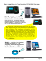
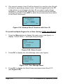
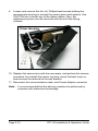
Basic Installation for Time Guardian FPT-40/A843 Package
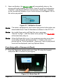
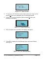
Step 1 – Wall Mount the FPT-40.
Connect the FPT-40 terminal using
direct connection with included USB
cable to host PC, or Ethernet cable for
network connection. Plug the in the AC
adapter to the FPT-40 and AC outlet and
the FPT-40 terminal will power up.
All employees must be enrolled at the FPT-40 terminal
with fingerprint and/or PIN password for identification
and validation. This employee information will be
synchronized with Time Guardian by performing polling
and downloading commands from the Time Guardian
software. This action is necessary to save the biometric
fingerprint templates for newly enrolled employees in
the Time & Attendance database while sending time,
Daylight Saving Time settings, hours worked for the
current payperiod, and employee assignments to the
FPT-40 terminal.
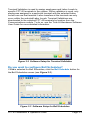
Step 2 – Install the Time Guardian
Software on the host PC. The
installation should start automatically,
but if it stalls, browse on CD to
Disk1\InstData\Windows\VM\install.exe
FPT-40 Installation & Operation Guide
Page iii
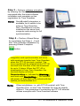
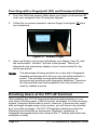
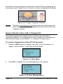
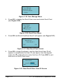
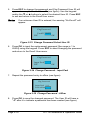
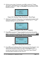
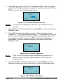
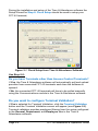
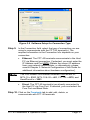
Step 3 – Perform software activation
by entering the Serial Number when
requested after the initial software
installation and complete on-line
registration for Time Guardian.
Note:
QuickBooks® integration is
available, but it needs to be
setup in Time Guardian.
Also, QuickBooks must be
installed on the same host
computer and running for full
synchronization.
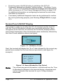
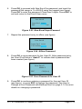
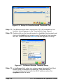
Step 4 – Perform Wizard Setup
by completing the Steps 1 - 9 and
end Time Guardian installation by
pressing Wizard Complete
button.
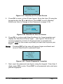
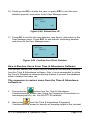
integration and synchronization will occur
with employee transfer from Time Guardian
when the FPT-40 terminal is polled. The
hours worked will be retained at the FPT-40
terminal from the date of the last download
for up to 14 days. When the FPT-40 is
downloaded to from Time Guardian, the
terminal display will show
Downloading…., followed by Working…,
and finish with Restarting…. The terminal
will power off then back on to refresh with the
options just downloaded to it.
Note:
Page iv
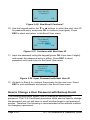
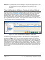
Other installations, i.e. with FPT40 terminal, with Time
Guardian Plus, or with Time Guardian Pro may be slightly
different. This procedure of connecting the FPT-40 terminal
utilizes examples with Time Guardian software.
FPT-40 Installation & Operation Guide
Chapter 1: FPT-40 Installation
Introduction
The FPT-40 Fingerprint terminal provides a sophisticated fingerprint
recognition and data collection terminal for use directly with the Amano
Time & Attendance software to provide a complete PC-based time and
attendance solution for small business. Fingerprint recognition is
considered to be one of the good forms of biometric security because of
its accuracy, affordability, and ease-of-use.
The FPT-40 Fingerprint terminal with Amano Time & Attendance
software provides a system that automatically calculates and
accumulates hours worked based on a company's payroll policies. This
system separates the hours worked into regular and overtime pay
categories and displays them at the terminal (see Normal Punch IN/OUT
Display on page 1-10).
The Amano Time & Attendance software also offers many sophisticated
features to simplify payroll preparation, such as: Lock Out, Revision, Red
Print with Grace Zones, Flexible Rounding Rules, Unpaid and Paid
Breaks, and Time Card Reports, to name a few. In addition, easy-to-read
management reports are available in hours or dollars to provide accurate
and timely labor information.
See Chapter 3 for details on setting up the Amano Time & Attendance
software on the host PC to communicate with the Fingerprint terminal.
In order to use fingerprint recognition, a user must enroll their fingerprint
in the fingerprint template database. The FPT-40 Fingerprint terminal will
record the user’s fingerprint template, encrypt it, and store the data.
When a user presents their finger for verification, a new template is
captured and compared to the pre-enrolled fingerprint in the database. If
there is a match, the user will be accepted by the FPT-40 Fingerprint
terminal.
One of the main benefits of this system is that it eliminates fraudulent
punches (“Buddy Punching”), while providing a comprehensive and
secure method when coupled with the Time & Attendance software to
accurately account for employee labor costs.
The FPT-40 Fingerprint terminal also provides re-punch protection at the
terminal when the "ReCheck Min” feature is set. Multiple punches within
the setting time frame will be verified but not recorded at the terminal in
flash memory (see Log Options Menu).
FPT-40 Installation & Operation Guide
Page 1-1
Unpacking Your FPT-40 Terminal
In addition to this guide, your FPT-40 terminal package should include
the following:
Fingerprint Data Collection Terminal
AC Adapter
USB-to-serial connector (RJ-11) with 50ft cable
6 foot Ethernet cable
Terminal mounting plate and hardware
Time Guardian/FPT-40 Quick-Start Guide (A843 package only)
Time Guardian CD (A843 package only)
Spare sensor lens/prism (see Replacing Optical Sensor Lens).
Locate this item and store in a safe place for possible
future use!! DO NOT DISCARD.
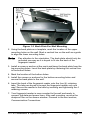
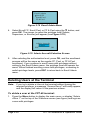
Understanding the FPT-40 Terminal Front Panel
The front panel of the FPT-40 Fingerprint terminal (see Figure 1-1)
contains the following controls:
LEDs: During normal standby operation (power on), the Green
LED will flash once per second, and stay on momentarily when a
user successfully verifies. If a user fails to verify, the Red LED will
momentarily stay on.
Note:
If the fingerprint reader does not follow the standard LED
operational parameters, please consult support.
Speaker: Provides audible voice verification of operations, i.e.,
"Thank you", "Incorrect Password", "Access Denied", "Invalid Id",
"Please try again", etc. See Advanced Options on page 2-39 for
voice control.
LCD Screen: Displays time, date, day, and operational information.
Fingerprint Sensor: Enrolls (creates) template and verifies
fingerprint.
Keypad: Used to input User ID, password, and perform menu
operation with the following keys:
ESC – to perform exit, cancel, ignore when using the Menus.
MENU – to access Menu structure.
OK – to confirm and/or save selection.
Page 1-2
FPT-40 Installation & Operation Guide
Note:
- power ON/OFF button.
or - to scroll down or up for menu operations.
Press the Power ON/OFF button to turn off the terminal.
Figure 1-1 FPT-40 Fingerprint Terminal Front View
Before Installing FPT-40 Fingerprint Terminal
Before installation, please make sure the unit is not connected to
power. Connect the power to the unit as the last step.
The recommended proper height to mount the device is 55 – 60 "
(1.4 – 1.5 meters).
Use only the AC adapter provided. Use of another AC adapter may
damage the unit and void the warranty.
Before connecting the device, please read and follow the installation
instructions. Failure to do so could cause equipment failure; Amano
is not responsible for any damages.
Please use the enclosed cable [either 6ft Ethernet, or 50 ft USB-toSerial cable to connect the FPT-40 Fingerprint terminal. If longer
serial cables for direct connect are required please consult Amano.
FPT-40 Installation & Operation Guide
Page 1-3
Wall Mounting
Warning! Before selecting a mounting location for your FPT-40
Fingerprint terminal, you must consider the following:
The mounting surface and hardware must be able to support the
unit’s weight, 1.35 lbs. (0.61 kg).
The area must be within the specified operating temperature &
humidity range (see Specifications on page 4-11)).
The FPT-40 Fingerprint terminal should be mounted in an
environment that avoids the conditions pictured in the following figure:
Close proximity to a wall outlet ( 6 ft), and a wall that can
accommodate signal and/or power conduits.
If using Ethernet, close proximity to an Ethernet connection ( 6 ft).
Amano recommends the following wall mounting procedure:
1. Loosen and remove the four (4) back plate retaining screws to
remove the back plate as shown (see Figure 1-2). Set the FPT-40
terminal face up on a flat surface.
Page 1-4
FPT-40 Installation & Operation Guide
Figure 1-2 Back Plate For Wall Mounting
2. Using the back plate as a template, mark the location of the upper
mounting holes on the wall. Mark a vertical line on the wall as a guide
to align the lower mounting holes.
Note:
Pay attention to the orientation. The back plate should only be
mounted one-way as it is keyed to fit into the back of the
fingerprint reader.
3. Install a screw or anchor at the mark and hang the back plate from the
top-mounting holes. Level the back plate by centering the vertical line
in the bottom holes.
4. Mark the location of the bottom holes.
5. Install the screws or anchors for the bottom-mounting holes and
secure the back plate to the wall.
6. Insert the back of the fingerprint reader onto the four (4) retaining
tabs. The tabs are keyed to accept the fingerprint reader only one
way! Secure the reader to the tabs by inserting and tightening the 4
retaining screws.
7. Your fingerprint reader is now mounted to the wall and ready to
connect the data and power lines. After wall mounting, remove the
dustproof film on the sensor window. Proceed to the next section,
Communication Connections.
FPT-40 Installation & Operation Guide
Page 1-5
Communication Connections
A connection between your Host PC with the Time & Attendance
software and the FPT-40 terminal(s) is/are based upon your setup.
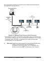
Serial Connection (Direct Connect)
You should use the Amano CommStik™ [part number AUS-10035x] (50
foot RJ-11 to USB) Communications Cable (included) to interface with
the host PC and Time & Attendance software.
RS-485 communications can be used for systems requiring up to 31
terminals. You will require the following accessories for each additional
RS-485 terminal:
AMX-206950: Communications Cable – 10’, 6 conductor RJ-11
AMX-206700: Junction Box
Time & Attendance
Software
PC Host
Figure 1-3 Serial Direct Connection with CommStik
Note:
Page 1-6
If the distance between the terminal and the host PC is more
than 50 feet, two junction boxes will be required.
FPT-40 Installation & Operation Guide
The connections between the host PC and multiple serial terminals for
this application are as follows:
Time & Attendance
Software
Time
PCGuardian
Host
Host PC
Amano
P/N AMX-206950
CommStik
Communications
Cable
Amano
P/N - AUS-100353
+
+
3
4
+
+
1
6
+ 2
5 +
Amano
P/N AMX-206700
3: SHIELD
5: + WHITE
6: (-) BLUE
Figure 1-4 Multiple Direct Connect Serial Terminals
* The maximum number of terminals is dependent upon the distance and
the quality of cabling used. It is recommended that Belden Low Voltage
Computer Cable, P/N 9841 or equivalent, be used to connect the
junction boxes for this application.
Warning! Please note that terminal #3 (used for the RS-485 cable
Shield) is disconnected from the internal RJ-11
receptacle of the junction box. This is deliberate; the
shield connection is NOT fed through to the Terminal.
FPT-40 Installation & Operation Guide
Page 1-7
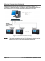
Ethernet Connection (Network)
Networked terminals can be connected to a standard 10Base-T or
100BaseTX computer network. In addition, each networked terminal can
have a group of up to 29 serial terminals connected via RS-485.
Time & Attendance
Software
PC Host
Figure 1-5 Networked Terminal(s)
Note:
Page 1-8
The serial connections for the RS-485 branch network are the
same as for the RS-485 wiring described previously.
FPT-40 Installation & Operation Guide
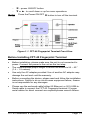
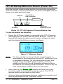
FPT-40 Startup Welcome Screen (Power On)
Once the terminal is wall mounted and the communication connections
have been made, connect the terminal to AC power (see Figure 1-6) and
power on to setup and enroll users.
Ethernet
Serial (DB9 to
USB CommStik)
DC/6V
Back Plate
Retaining Screws
AC Power
Figure 1-6 FPT-40 Fingerprint Terminal Bottom View
To start-up perform the following:
Ensure the AC Power Adapter is connected to the FPT-40 terminal
and plugged into an outlet. Press the power button. The FPT-40
terminal will display the splash screen, perform a diagnostic check,
and then display the Welcome screen (see figure).
Figure 1-7 Welcome Screen
Note:
The time and date can be set with the terminal keypad, or
downloaded to the terminal from the host PC utilizing the Time
& Attendance software. The information such as date, time,
daylight saving time (DST), finger templates, and hours
worked sent from the Time & Attendance software will have
precedence over existing similar information. That is to say the
Time & Attendance software will act as the master.
Upon power up, the Green LED indicator will blink once every
second to signify the terminal is operating properly. The FPT-40
terminal should now be ready to enroll users.
All normal time and attendance functions (validation for punch in/out)
must be performed from the "Welcome" screen.
FPT-40 Installation & Operation Guide
Page 1-9
Press the power On/Off button to shutdown the FPT-40
Fingerprint terminal and display "halting system….Shutdown 2 secs,
1sec". The FPT-40 terminal will retain all templates and transactions
while the power is off. See Power Management Menu on page 2-40
for additional information on configuring the terminal for auto-sleep
and wake up functions.
If necessary additional diagnostic tests can be performed to confirm
the unit is performing properly (see Running Diagnostics on page
4-1).
Normal Punch IN/OUT Display
The system is ready to use after the FPT-40 terminal and the host PC
with the Time & Attendance software are connected and setup. Upon
recognition at the terminal, the terminal will first briefly display his/hers
name [first 8 characters of the first and last name combined], followed by
the User ID and validation status (see figure).
Verify
John Doe
User ID 00001
Verified.
Figure 1-8 Validation Screen
Next, the terminal will display the "As of" date followed by the current pay
period hours worked for the user that just punched in (see figure for
example).
Figure 1-9 Hours Worked for Pay Period
Note:
The current pay period information is transferred from the Time
& Attendance software to the terminal during a download and
can be retained at the terminal for up to 14 days between
downloads.
Page 1-10
FPT-40 Installation & Operation Guide
Chapter 2: FPT-40 Operation
Daily FPT-40 Use
The following "Daily Use" sections assume the FPT-40 Fingerprint
terminal has been setup with enrolled users and system options have
been defined. Please see Enrolling Users on page 2-4 and the other
sections for enrollment details, etc.
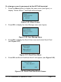
Punching with a Fingerprint (FP)
1. From the Welcome screen place your enrolled finger in the sensor
window (see figure).
Figure 2-1 Punching Using Biometrics
Note:
If your primary finger is damaged [i.e., cut], please use an
enrolled backup finger or a password to ensure a successful
punch.
2. Follow the on screen prompt, "FP Verify…Remove Finger"
(see figure).
FP Verify
Remove Finger
Figure 2-2 Fingerprint (FP) Verify
FPT-40 Installation & Operation Guide
Page 2-1
3. Upon verification, the Green LED will momentarily stay on, the
screen will briefly display your Name, User ID, and the confirmation
"Verified." (see figure) with the voice prompt "Thank you", followed
by the momentary display of your hours worked (see Figure 1-9) for
the active pay period.
Verify
John Doe
User ID 00001
Verified.
Figure 2-3 Validation Screen
Note:
The name, assignments, and current pay period information are
downloaded from Time & Attendance software to the FPT-40.
Note:
An invalid finger entry will flash the error message,
"Please Try Agn.", with the same voice prompt. The Red LED
will momentarily stay on.
Note:
When ReCheck Min is set, if an employee punches more than
once within the time setting [usually 1 – 2 mins.], the voice
prompt will be "Punch accepted…thank you" and no pay period
hours will be displayed (see Log Options Menu).
Punching with a Password (Pwd)
1. From the Welcome screen enter your User ID using the keypad
and press OK to confirm ID (see figure).
Figure 2-4 Enter User ID
Page 2-2
FPT-40 Installation & Operation Guide
2. Input your password to affirm (see figure).
Pwd Affirm
User ID 00001
Input Pwd *****
Figure 2-5 Input Password
Note:
An invalid password entry will flash the error message,
"Error Pwd.", and the voice prompt, "Incorrect password". The
Red LED will stay on until the correct password is entered or
the password entry times out and the terminal returns to the
Welcome screen.
Note:
The user will be prompted to "Place Finger" if they do not have
a password.
3. Upon verification, the screen will display your Name, User ID, and
the confirmation "Verified." with the voice prompt "Thank you".
Next, the display will momentarily show the "As of" date followed by
the current pay period hours worked for the user that just punched in
(see figure for example).
Figure 2-6 Hours Worked for Pay Period
Note:
When ReCheck Min is set, if an employee punches more than
once within the time setting [usually 1 – 2 mins.], the voice
prompt will be "Punch accepted…thank you" and no pay
period hours will be displayed (see Log Options Menu).
FPT-40 Installation & Operation Guide
Page 2-3
Punching with a Fingerprint (FP) and Password (Pwd)
1. From the Welcome screen either place your finger on the sensor or
enter your assigned User ID using the keypad.
2. Follow the on screen prompt to remove finger (see figure) or input
your password.
Figure 2-7 Remove Finger
3. Upon verification, the screen will display your Name, User ID, and
the confirmation "Verified." with the voice prompt "Thank you"
followed by the momentary display of your hours worked for the
active pay period.
Note:
The advantage of being enrolled as a user with a fingerprint
template and password is that you can use either method to
punch. This provides an automatic backup should you
encounter any problems with fingerprint validation. Therefore,
the first method used and accepted is the only method you
need to validate a punch.
Enrolling Users at the FPT-40 Terminal
After installing the FPT-40 Fingerprint terminal and powering on, you
may begin enrolling users. If this is the first enrollment in a new or empty
system, everyone will be able to enroll. However, if there are any users
with privileges already setup in the system, you will have to be enrolled
by a user with privileges. The FPT-40 fingerprint reader provides the
following three methods for enrollment; fingerprint, password, or
fingerprint and password [in this instance the 1st method submitted and
accepted is used].
Page 2-4
FPT-40 Installation & Operation Guide
Caution! Use care when enrolling users at the terminal as the ESC
button can alter the entry fuctions during some
operations.
Introduction
User Identification/Verification
This is the process of comparing a user's finger against the stored map,
and/or verifying a user from a stored password number (5 digit max).
After performing the verification process the system will indicate success
or failure while also storing all verified punches for transfer to the Time &
Attendnace software.
Threshold
The threshold is a predefined number, often controlled by the
administrator, which establishes the degree of correlation necessary for
a sucessful match. If the score from the template comparison exceeds
the threshold, the templates are considered a match. The threshold
establishes a balance between False Acceptance Rate (FAR) and False
Rejection Rate (FRR). FAR indicates the probability that a biometric
system will incorrectly identify an individual or will fail to reject an
imposter.
You can set the threshold for all users. For a user who has a difficult
fingerprint verification, it is recommended to use ID & fingerprint
verification (match one-to-one). Raising the threshold increases security,
while lowering it increases the passing ratio. The correct balance can be
vital. For example, a user whose finger is worn or injured should have a
reduced threshold.
The FAR and FRR values affect each other. As FAR is increased, FRR
should be decreased. The default one-to-many threshold is 35, while the
1:1 matching default threshold is 15 (see the following table).
Table 2-1 Recommended Threshold Level Settings
FRR
FAR
One-to-Many
One-to-One
High
Low
45
25
Middle
Middle
35
15
Low
High
25
10
FPT-40 Installation & Operation Guide
Page 2-5
Priviledge (Status) Levels
The status levels define the ability of a user to perform specified
administrator and other tasks including the ability to view, edit, add, and
renew specified information categories. Four status levels can be
assigned at the FPT-40 terminal or from the Time & Attendance
software, and modified as required. These four (4) levels (see Defining
Privileges with Enrolling Admin Option on page 2-28) are:
User – person whose identity must be verified to punch and have
their attendance recorded in the Time & Attendance software.
Cannot perform any enroller, supervisor, and administrator functions.
Enroller – person who is authorized to enroll users or delete them
from the FPT-40 Fingerprint terminal.
Supervisor – person who can perform all operations, except set
advanced options and enroll a user with Admin priviledges.
Administrator – person who has access to all functions, including
system setup. (see procedure for clearing).
Proper Finger Placement
Make sure the fingerprint image captured contains the core part of
desired finger, because a fingerprint is the impression of the friction
ridges of all or any part of the finger. Also when enrolling a finger, use a
slightly adjusted angle for each finger press, i.e, one to the center, one
inclined slightly to the left, and a third inclined slightly to the right. If these
techniques are followed; the success rate should increase dramatically.
The correct way to place a finger on the sensor is:
Place the finger flat on the center of the sensor surface
(see figure for front and side view).
Page 2-6
FPT-40 Installation & Operation Guide
The wrong ways to place a finger on the sensor are:
The following hints are provided as suggestions to help obtain a good
fingerprint enrollment.
Table 2-2 Fingerprint Enrollment Hints
Problem
Suggested Solution
Fingerprint is too dry or dirty.
Wipe finger, and/or moisten.
Not enough pressure.
Place finger firmly and flat on the
sensor.
How to select finger?
Use the finger alongside your thumb.
Select fingers that are not worn or
injured. If the fingers are small, use the
thumb.
Finger placement?
Place at least 2/3 of the finger firmly on
the sensor. Do not touch the finger too
fast and do not move the finger on the
sensor until prompted.
Finger pattern change?
Re-enroll your finger if your fingerprint
changes as a result of an injury, etc.
Other reasons
Use password registration as an
alternative for people with poor quality
fingerprints. Also, the threshold setting
can be reduced.
FPT-40 Installation & Operation Guide
Page 2-7
Enrollment is the procedure to associate a User ID with a fingerprint by
scanning a user's finger three (3) times to create a template (see figure).
Figure 2-8 Finger Template Creation
Note:
Enrolling more than two (2) fingers per user might adversely
effect the amount of user templates that can be stored in the
fingerprint reader.
How to Enroll a User with a Fingerprint
The following procedure details how to enroll a new user with a
fingerprint template. It is suggested to enroll 2 fingers so the employee
has a backup finger when needed, i.e., bandaid or finger injury.
To enroll a fingerprint at the FPT-40 terminal:
1. Press the Menu button to display the main menu (see figure), or
display "Admin Affirm 1" and login with privileges.
Menu
User Manage
Options
Sys Info
Figure 2-9 Main Menu
2. Press OK to display the User Manage menu (see figure)
User Manage
Enroll User
Enroll Admin
Delete
Figure 2-10 User Manage Menu
Page 2-8
FPT-40 Installation & Operation Guide
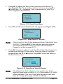
3. Press OK to display the Enroll User menu and select Enroll FP
(see Figure 2-11). The possible enrollment choices using the or
buttons are; FP = fingerprint, Pwd = password only, and FP &
Pwd = fingerprint & password).
Enroll User
Enroll FP
Enroll Pwd
FP & Pwd
Figure 2-11 Enroll User Menu
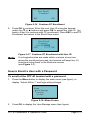
4. Press OK and Enroll FP New Enroll? will appear (see Figure 2-12).
Enroll FP
New Enroll ?
ESC
OK
Figure 2-12 New Enroll FP Screen
Note:
If this is the first User ID the display will show "New Enroll User
ID 00001". Pressing ESC at this step will place the terminal
into the Backup Enroll mode (see How to Enroll Multiple
Fingers for a User on page 2-21).
5. Press OK to begin enrollment, and New Enroll User ID will appear to
accept/enter the User ID (see figure). Enter the User ID using the
keypad and/or the or buttons. Press ESC to exit and return to
the Enroll User menu.
New Enroll
User ID 00002
ESC
OK
Figure 2-13 New Enroll User ID Screen
Note:
The default User ID is 5 digits, so any number less than 5
digits will have zeros in front of it, i.e., if the number is 2, 00002
will be displayed. The User ID will auto-sequence each new
User ID + 1 digit. [the range is 00001 to 65534].
FPT-40 Installation & Operation Guide
Page 2-9
6. Press OK to proceed and display "New Enroll Place Finger…"
(see figure). Follow the on screen prompts for a total of 3 finger
presses to complete the process, or press ESC to exit to the Enroll
User menu.
New Enroll
04535-0
Place Finger
ESC/Exit
+
+ +
Figure 2-14 Place Finger 1st Pass
Note:
The system may prompt you with voice and on screen
warnings if errors in the FP enrollment process occur. For
example, if that ID already has the same finger enrolled, the
voice prompt will say "Duplicate Finger" while the screen will
display "FP Enrolled Alrd" [for fingerprint enrolled already].
Note:
The system will not allow duplicate enrollment of the same
finger for the same or different User IDs. You must enroll a
different finger.
7. After the 3rd successful finger press, the display will show the User ID
followed by “ – 0” (see figure) to indicate that one (1) finger template
exists for this ID.
New Enroll
00002-0
ESC
OK(Save)
Figure 2-15 Save User ID with FP Template
8. Press OK to save the finger template, and the system will prompt to
continue for another user enrollment (see figure).
Note:
At this time if you press ESC you will exit New FP enrollment
and enter the Backup Enroll mode. This mode can be used to
create more than one (1) finger template for a User ID. A
backup finger is recommended as an alternate identification
resource.
Page 2-10
FPT-40 Installation & Operation Guide
New Enroll
Continue?
ESC
OK
Figure 2-16 Continue FP Enrollment
9. Press OK to continue. Enter the next User ID using the keypad
and/or the or buttons and press OK to accept the User ID. [go
back to Step 6 to continue with FP enrollment]. Press ESC to end FP
Enrollment and return to the Enroll User menu.
New Enroll
Continue?
User ID 00003
ESC
OK
Figure 2-17 Continue FP Enrollment with User ID
Note:
If no keypad entries are made within a minute at any time
during the enrollment process, the terminal will beep two (2)
times and return back to the Welcome screen
(see Figure 1-7).
How to Enroll a User with a Password
To enroll at the FPT-40 terminal with a password:
1. Press the Menu button to display the main menu (see figure), or
display "Admin Affirm 1" and login with privileges.
Menu
User Manage
Options
Sys Info
Figure 2-18 Menu Screen
2. Press OK to display the User Manage menu (see figure).
FPT-40 Installation & Operation Guide
Page 2-11
User Manage
Enroll User
Enroll Admin
Delete
Figure 2-19 User Manage Menu
3. Press OK to display the Enroll User menu and select Enroll Pwd
(see Figure 2-20).
Enroll User
Enroll FP
Enroll Pwd
FP & Pwd
Figure 2-20 Enroll User Menu
4. Press OK and Enroll Pwd New Enroll? will appear (see Figure 2-21).
Enroll Pwd
New Enroll ?
ESC
OK
Figure 2-21 New Enroll Pwd Screen
5. Press OK to begin Enrollment, and the New Enroll User ID will
appear to accept/enter the User ID (see figure). Use the keypad
and/or the or buttons to enter the User ID. Press ESC to exit
and return to Enroll User menu.
New Enroll
User ID
ESC
00002
OK
Figure 2-22 New Enroll Enter User ID Screen
Page 2-12
FPT-40 Installation & Operation Guide
6. Press OK to proceed with New Enroll for password, and input the
password [the range is 1 to 65534] using the keypad (see figure).
Press OK to enter the password if less than 5 digits. Press ESC to
exit and return to the Enroll User menu.
New Enroll
Input Pwd xxxxx
ESC
OK
Figure 2-23 New Enroll Input Pasword
7. Repeat the password entry to affirm (see figure).
New Enroll
Input Pwd xxxxx
Pwd Affirm _
Figure 2-24 Affirm Password
8. Press OK to save password for the User ID. After password entry,
the User ID will have a “dash P” to indicate that a password has
been created (see figure).
New Enroll
00006-P
ESC
OK(Save)
Figure 2-25 Save Password for User ID
9. Press OK to continue entering a password for the next User ID
(see figure), or press ESC to change the password. See How to
Change a User Password with Backup Enroll on page 2-14 for more
details on changing a password.
FPT-40 Installation & Operation Guide
Page 2-13
New Enroll
Continue?
ESC
OK
Figure 2-26 New Enroll Continue?
10. Use the keypad and/or the or buttons to select the next User ID
for password entry, and press OK to continue (see figure). Press
ESC to abort and return to the Enroll User menu.
New Enroll
Continue?
UserID 00007
ESC
OK
Figure 2-27 Continue with Next User ID
11. Input the password using the keypad [press OK if less than 5 digits],
and repeat the password entry to affirm. Press ESC to abort
password entry and return to the Enroll User menu.
New Enroll
Continue ?
Input Pwd _
ESC
OK
Figure 2-28 Input Password with Next User ID
12. Go back to Step 8 to continue the process for the next user. Press
ESC to end enrollment and return to the Enroll User menu.
How to Change a User Password with Backup Enroll
The following procedure details how to change an existing user
password. The FP & Pwd Enroll procedure could also be used to change
the password, but you will have to enroll another finger to get password
access. Therefore, the following is recommended as the easiest method
for changing a password.
Page 2-14
FPT-40 Installation & Operation Guide
To change a user's password at the FPT-40 terminal:
1. Press the Menu button to display the main menu (see figure), or
display "Admin Affirm 1" and login with privileges.
Menu
User Manage
Options
Sys Info
Figure 2-29 Menu Screen
2. Press OK to display the User Manage menu (see figure).
User Manage
Enroll User
Enroll Admin
Delete
Figure 2-30 User Manage Menu
3. Press OK to display the Enroll User menu and select Enroll Pwd
(see Figure 2-31).
Enroll User
Enroll FP
Enroll Pwd
FP & Pwd
Figure 2-31 Enroll User Menu
4. Press OK and Enroll Pwd New Enroll? will appear (see Figure 2-32).
Enroll Pwd
New Enroll ?
ESC
OK
Figure 2-32 Enroll Pwd New Enroll Screen
FPT-40 Installation & Operation Guide
Page 2-15
5. Press ESC to change the password and Chg Password User ID will
appear to accept/enter the User ID (see figure). Use the keypad
and/or the or buttons to select the desired User ID. Press ESC
to exit and return to the Enroll User menu.
Note:
If an unknown User ID is entered, the warning "No Enroll!" will
appear.
Chg Password
UserID 00001
ESC
OK
Figure 2-33 Change Password Select User ID
6. Press OK to input the replacement password [the range is 1 to
65534] using the keypad. Press ESC to abort changing the password
and return to the Enroll User menu.
Chg Password
Input Pwd _
ESC
OK
Figure 2-34 Change Password - Input Pwd
7. Repeat the password entry to affirm (see figure).
Chg Password
Input Pwd *****
Pwd Affirm_
Figure 2-35 Change Password - Affirm
8. Press OK to save the changed password. The User ID will have a
"-P" after it to indicate a password has been created (see figure).
Page 2-16
FPT-40 Installation & Operation Guide
Chg Password
00001- P
ESC
OK(Save)
Figure 2-36 Change Password - Save
9. Press OK to continue changing passwords for other Users (see
figure), or press ESC to exit changing passwords and go to "New
Enroll" (see How to Enroll a User with a Password on page 2-11.
Chg Password
Continue?
ESC
OK
Figure 2-37 Continue with Next User ID
10. Use the keypad and/or the or buttons to select the next User ID
for password change (see figure), and press OK to input the new
password. Press ESC to return to the Enroll User menu.
Chg Password
Continue?
User ID 00001
ESC
OK
Figure 2-38 New Enroll Input Pwd
11. Input the new password and affirm. See Step 8 to continue the
process, or press ESC to exit and return to the Enroll User menu.
Chg Password
00002- P
ESC
OK(Save)
Figure 2-39 Save Change Password
FPT-40 Installation & Operation Guide
Page 2-17
How to Enroll a User with Fingerprint and Password
The following procedure details how to enroll a new user using both a
fingerprint and a password. When this procedure is used, the user only
has to validate with either a fingerprint or a password. The user does not
have to use both the fingerprint and password to validate an in/out punch
for time recording.
To enroll at the FPT-40 terminal with a FP & Pwd:
1. Press the Menu button to display the main menu (see figure), or
display "Admin Affirm 1" and login with privileges.
Menu
User Manage
Options
Sys Info
Figure 2-40 Menu Screen
2. Press OK to display the User Manage menu (see figure)
User Manage
Enroll User
Enroll Admin
Delete
Figure 2-41 User Manage Menu
3. Press OK to display the Enroll User menu and select FP & Pwd
(see Figure 2-42).
Enroll User
Enroll FP
Enroll Pwd
FP & Pwd
Figure 2-42 Enroll User Menu
4. Press OK and FP & Pwd New Enroll? will appear (see Figure 2-43).
Page 2-18
FPT-40 Installation & Operation Guide
FP & Pwd
New Enroll ?
ESC
OK
Figure 2-43 New Enroll FP & Pwd Screen
5. Press OK to enter a User ID (see figure). Enter the User ID using the
keypad and/or the or buttons. Press ESC to exit to Backup
Enroll (see How to Change a User Password on page 2-14).
New Enroll
User ID
ESC
00002
OK
Figure 2-44 New Enroll User ID Screen
6. Press OK to continue with New Enrollment for finger template and
display the New Enroll Place Finger… (see figure). Follow the on
screen prompts for a total of 3 finger presses to complete the
process. Wait for the screen to prompt you each time to place your
finger!
Note:
Pressing ESC at this step will bypass finger enrollment and
move to New Enroll for password input.
New Enroll
00014-0
Place Finger . . .
ESC/Exit
Figure 2-45 Create Fingerprint Template
7. Next, input the password (see figure) using the keypad. If less than 5
digits, press OK to enter. Press ESC to exit password entry and save
just the fingerprint.
FPT-40 Installation & Operation Guide
Page 2-19
New Enroll
00014-0
Input Pwd ESC
OK
Figure 2-46 New Enroll Input Pasword
8. Repeat the password entry to affirm, and display the User ID with a
"-0P" (see Figure 2-48) to indicate that this User has 1 finger
template ("0") and a password ("P")
New Enroll
00014-0P
Input Pwd xxxxx
Pwd Affirm _
Figure 2-47 Affirm New Password
9. Press OK to save the finger template & password (see figure) and
display New Enroll Continue?
New Enroll
00014-0P
ESC
OK(Save)
Figure 2-48 Save Password for User ID
10. Press OK to Continue (see figure) with FP & Pwd enrollment, or
press ESC to move to Backup Enroll Continue? to change finger
template and password for a User ID.
New Enroll
Continue?
ESC
OK
Figure 2-49 New Enroll Continue?
Page 2-20
FPT-40 Installation & Operation Guide
11. Press OK to enter the next User ID (see figure) for a finger template
and password. See Step 6 to continue the process to enroll the next
user. Press ESC to display Input Pwd screen to enter a password.
New Enroll
Continue?
UserID 00015
ESC
OK
Figure 2-50 Continue with Next User ID
How to Enroll Multiple Fingers for a User
The following procedure details how to enroll multiple fingerprint
templates for a single user. When this procedure is used, the user now
has an alternate finger to use as a backup. Two separate fingers per
user are recommended to be enrolled for backup, but enrolling more
than two fingers per user will reduce the amount of users that can be
stored in the reader.
There are two different scenarios for enrolling multiple fingers for the
same user. The first scenario is to add an additional finger template for
an exisiting enrolled user. The second scenario is to enroll more than 1
finger for a user during initial FP enrollment at the terminal.
To enroll a backup finger for a User ID already enrolled:
1. Press the Menu button to display the main menu (see figure), or
display "Admin Affirm 1" and login with privileges.
Menu
User Manage
Options
Sys Info
Figure 2-51 Menu Screen
2. Press OK to display the User Manage menu (see figure).
FPT-40 Installation & Operation Guide
Page 2-21
User Manage
Enroll User
Enroll Admin
Delete
Figure 2-52 User Manage Menu
3. Press OK to display the Enroll User menu and select Enroll FP
(see Figure 2-53).
Enroll User
Enroll FP
Enroll Pwd
FP & Pwd
Figure 2-53 Enroll User Menu
4. Press OK and Enroll FP New Enroll? will appear (see Figure 2-54).
Enroll FP
New Enroll ?
ESC
OK
Figure 2-54 Enroll FP Screen
5. Press ESC to exit New Enroll and initiate Backup Enroll. The lowest
numeric User ID will be shown first, and the User IDs will be listed in
ascending numeric order. Use the keypad and/or the or buttons
to enter/select the User ID you want to add a finger template to.
Backup Enroll
User ID 00001
ESC
OK
Figure 2-55 Backup Enroll User ID Screen
6. With the desired User ID selected, press OK to add another finger
template (see figure), and the User ID will indicate that an additional
template is being added by the dash number after the User ID [i.e.,
00010 – 1 means user ID # 10 has 2 templates] (see figure).
Page 2-22
FPT-40 Installation & Operation Guide
Backup Enroll
00001-1
Place Finger ...
ESC/Exit
Figure 2-56 Backup Finger Enrollment - Place Finger 1st Pass
Note:
The system may prompt you with voice and on screen
warnings if errors in the enrollment process occur. For
example, if that ID already has the same finger enrolled, the
voice prompt will say "Duplicate Finger" while the screen will
display "FP Enrolled Alrd".
Note:
The system will not allow duplicate enrollment of the same
finger. You must enroll a different finger.
7. Follow the on screen prompts for a total of 3 finger presses to add
the finger template, or press ESC to return to the Enroll User menu.
Press OK to save the 2nd finger template which is indicated by the 5digit User ID followed by a "dash 1" (see figure).
Backup Enroll
00001-1
ESC
OK(Save)
Figure 2-57 Backup Enroll User ID
8. Press OK, to continue with Backup Enrollment (see figure), or press
ESC to discontinue the Backup Enrollment process and return to the
Enroll User menu.
Backup Enroll
Continue?
ESC
OK
Figure 2-58 Backup Enroll Continue
FPT-40 Installation & Operation Guide
Page 2-23
9. The current numeric User ID will be shown first, and the User IDs will
be listed in ascending numeric order. Use the keypad and/or the
or buttons to enter/select the User ID you want to add a finger
template to, and press OK. See Step 6 to continue with the backup
enrollment process. Press ESC to abort the process and return back
to the Enroll User menu.
Backup Enroll
Continue?
User ID 00001
ESC
OK
Figure 2-59 Backup Enroll Continue with User ID
To enroll multiple fingers for a User during initial enrollment:
1. Press the Menu button to display the main menu (see figure), or
display "Admin Affirm 1" and login with privileges.
Menu
User Manage
Options
Sys Info
Figure 2-60 Menu Screen
2. Press OK to display the User Manage menu (see figure)
User Manage
Enroll User
Enroll Admin
Delete
Figure 2-61 User Manage Menu
3. Press OK to display the Enroll User menu and select Enroll FP
(see Figure 2-62).
Page 2-24
FPT-40 Installation & Operation Guide
Enroll User
Enroll FP
Enroll Pwd
FP & Pwd
Figure 2-62 Enroll User Menu
4. Press OK and Enroll FP New Enroll? will appear (see Figure 2-63).
Enroll FP
New Enroll ?
ESC
OK
Figure 2-63 New Enroll FP Screen
5. Press OK to begin new enrollment, and New Enroll User ID will
appear to enter the User ID (see figure) using the keypad and/or the
or buttons. Press ESC to exit and return to the Enroll User
menu.
New Enroll
UserID 00028
ESC
OK
Figure 2-64 New Enroll User ID Screen
6. Press OK to proceed with the selected User ID and display New
Enroll Place Finger… (see figure). Follow the on screen prompts for
a total of 3 finger presses to complete the process, or press ESC to
exit and return to the Enroll User menu.
New Enroll
00028-0
Place Finger . . .
ESC/Exit
Figure 2-65 New Enroll - Place Finger 1st Pass
FPT-40 Installation & Operation Guide
Page 2-25
Note:
The FPT-40 Fingerprint terminal will not allow duplicate finger
enrollment for the same or even different User IDs. You must
enroll a different finger.
7. After the 3rd successful finger press, the display will show the 5-digit
User ID followed by “– 0” (see figure) to indicate that the first (0)
finger template has been created for this ID.
New Enroll
00028-0
ESC
OK(Save)
Figure 2-66 Save User ID with FP Template
8. Press OK to save the finger template, and the system will prompt to
continue with another new enrollment (see figure) for the next User
ID.
Note:
At this time if you press ESC you will exit New FP enrollment
and enter the Backup Enroll mode. This mode can be used to
create an additional finger template for the User ID. A backup
finger is recommended as an alternate identification resource.
New Enroll
Continue?
ESC
OK
Figure 2-67 Continue FP Enrollment
9. Press ESC to initiate Backup Enroll to add a second finger template
for this User ID.
Backup Enroll
Continue?
User ID 00028
ESC
OK
Figure 2-68 Backup Enroll User ID Screen
Page 2-26
FPT-40 Installation & Operation Guide
10. With the same User ID selected, press OK to add the 2nd finger
(see figure), and follow the on screen prompts for a total of 3 finger
presses to add the 2nd finger, or press ESC to exit and return to the
Enroll User menu.
Backup Enroll
00028-1
Place Finger ...
ESC/Exit
Figure 2-69 Backup Finger Enrollment - Place Finger
11. After the 3rd successful finger press, the display will show the 5-digit
User ID followed by a “–1” (see figure) to indicate that a 2nd finger
template has been created for this ID.
Backup Enroll
00028-1
ESC
OK(Save)
Figure 2-70 Confirm User ID & FP Template
12. Press OK to save the 2nd finger template for the User ID, and the
system will prompt to continue backup enrollment (see figure). Press
ESC to discontinue the Backup Enrollment process and return to the
Enroll User menu to select another form of enrollment.
Backup Enroll
Continue?
ESC
OK
Figure 2-71 Backup Enroll Continue
13. Press OK, and the Backup Enroll Continue? User ID will appear (see
figure) with the current User ID or enter a different User ID to
continue the backup enrollment process. Press ESC to abort the
process and return back to the Enroll User menu when finished
enrolling finger templates for this User ID.
FPT-40 Installation & Operation Guide
Page 2-27
Backup Enroll
Continue?
User ID 00028
ESC
OK
Figure 2-72 Backup Enroll Continue User ID
Defining Privileges with Enrolling Admin Option
After power on and setting up the FPT-40 Fingerprint terminal, you may
begin enrolling users. If this is the first enrollment in a new or empty
system, everyone will be able to enroll. However, if there are any user
privileges setup in the terminal, you will need, at a minimum, "Enroller"
level privileges to enroll a new user. The FPT-40 Fingerprint terminal
contains a privileges option to prevent unauthorized personel from
changing terminal parameters. This security option provides three (3)
different levels of authorized use, which are: an enroller, a supervisor,
and an administrator with the following privileges:
Enroller Privilege Level
The Enroller can only access the User Manage and Sys Info menus.
The Enroller can not delete any user's at the terminal.
The Enroller has full access to the enrollment functions for a new
user, and also changing an existing user via Backup Enroll.
The Enroller has access to the "Enroll Admin" function, but can only
create a user with "Enroller" level privileges.
Supervisor Privilege Level
A Supervisor can access all 3 main menus; the User Manage,
Options, and Sys Info menus. However, a Supervisor can not access
the Auto Test menu [from Options menu], the Comm Key [from
Comm Opt menu, and most importantly, the Adv Opt menu [from
System Options].
A Supervisor can only delete a user with no privileges or Enroller
privileges at the terminal.
A Supervisor has full access to the enrollment functions for a new
user, and also changing an existing user via Backup Enroll.
A Supevisor has access to the "Enroll Admin" function, but can only
create a user with "Supervisor" and "Enroller" level privileges.
Page 2-28
FPT-40 Installation & Operation Guide
Admin Privilege Level
The Administrator has full access to all menus, user deletion [can
not delete an Admin], enrollment, and deleting privileges and/or
data from the Adv Opt menu.
Note:
The only way to delete a user with Admin privileges at the
terminal is to use the "Clear Admin Pri" [clear administrator
priorities] command from the Adv Option menu.
Note:
When creating privileges at the terminal it is strongly
recommended to create at least one user with "Admin"
privileges first so that you would always have full access at the
terminal if required. User privileges can also be set from the
Amano Time & Attendance software.
Note:
The only way to setup user privileges is at the FPT-40 and
these privileges will be transferred to the Time & Attendance
software when the FPT-40 is polled.
To enroll a User at the FPT-40 terminal with privileges:
1. Press the Menu button to display the main menu (see figure). If
users with privileges have already been setup the Welcome screen
will display "Admin Affirm 1" on the top. If this is the case, you must
login with privileges first to get access to the main menu.
Menu
User Manage
Options
Sys Info
Figure 2-73 Main Menu
2. Press OK to display the User Manage menu and select Enroll Admin
(see figure).
User Manage
Enroll User
Enroll Admin
Delete
Figure 2-74 User Manage Menu
3. Press OK to display the Enroll Admin menu (see Figure 2-75).
FPT-40 Installation & Operation Guide
Page 2-29
Enroll Admin
Enroll FP
Enroll Pwd
FP & Pwd
Figure 2-75 Enroll Admin Menu
4. Select Enroll FP, Enroll Pwd, or FP & Pwd using the button, and
press OK. The screen to select the privilege level [Admin,
Supervisor, or Enroller] will appear (see Figure 2-76).
Admin Accredit
Admin
ESC
OK
Figure 2-76 Admin Accredit Selection Screen
5. After selecting the authorization level, press OK, and the enrollment
process will be the same as the regular FP, Pwd, or FP & Pwd
enrollment. If you continue to enroll users with privileges without
exiting to the Enroll Admin menu, the privilege level will remain the
same. When finished enrolling a user with privileges, or desiring to
switch privilege levels, press ESC to return back to Enroll Admin
menu.
Deleting Users at the Terminal
Note:
If you try to delete a User at the terminal without having the
required privilege, a message "Access Deny!" will briefly appear,
and the display will return to the previous screen.
To delete a user at the FPT-40 terminal:
1. Press the Menu button to display the main menu, or display "Admin
Affirm 1" on the top of the Welcome screen (see figure) and login as
a user with privileges.
Page 2-30
FPT-40 Installation & Operation Guide
Figure 2-77 Menu Screen
2. To login from the Welcome screen either place your finger on the
sensor or enter your assigned User ID using the keypad.
3. Follow the on screen prompt to remove finger or input your
password (see figure).
Pwd Affirm
User ID 00001
Input Pwd *****
Figure 2-78 Input Password
4. Once accepted, the main Menu will display (see figure).
Menu
User Manage
Options
Sys Info
Figure 2-79 Main Menu
5. Press OK to display the User Manage menu and select Delete
(see figure).
User Manage
Enroll User
Enroll Admin
Delete
Figure 2-80 User Manage Menu
FPT-40 Installation & Operation Guide
Page 2-31
6. Press OK to select the User ID (see Figure 2-81). Use the keypad
and/or the or buttons to navigate to the desired User ID. Press
ESC to return to the User Manage menu.
Delete
UserID 00001
ESC
OK
Figure 2-81 Delete Enrolled User ID
Note:
The screen will display "No Enroll!" if an invalid user ID is
entered.
7. Press OK to confirm the User ID, or press ESC to return to the User
Manage menu.
8. Press OK to begin the deletion process. The sequence of any
deletion is: 1st the fingerprint (see figure), 2nd the password, and last
the User ID (see figure). The items deleted will depend upon what
the user has created. First press OK to delete the fingerprint. or
press ESC to exit the deletion process, and return to the User
Manage menu.
Del Fingerprint
00002-0
ESC
OK
Figure 2-82 Delete Fingerprint
Note:
If the user has multiple finger templates the sequence of
deletion will be the last finger template to first, next the
password, etc.
9. Next press OK to delete the password, or press ESC to exit the
password deletion process, and return to the User Manage menu.
Del Password
00002 - P
ESC
OK
Figure 2-83 Delete Password
Page 2-32
FPT-40 Installation & Operation Guide
10. Finally press OK to delete the user, or press ESC to exit the user
deletion process, and return to the User Manage menu.
Del User
00002
ESC
OK
Figure 2-84 Delete User ID
11. Press OK to confirm the user deletion (see figure), and return to the
User Manage menu. Press ESC to exit without confirming deletion
and return to the User Manage menu.
Del User
Delete ?
ESC
OK
Figure 2-85 Confirm User ID for Deletion
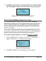
How to Restore Users From Time & Attendance Software
You can still retrieve the Users you just deleted at the terminal [location]
from the Time & Attendance software. Also, it is recommended to utilize
the Time & Attendance software backup feature to protect the database
which contains the maps, etc.
The sequence to restore users from the Time & Attendance
software is:
1. First press the
button from the Time & Attendance
Communications screen (see Using the Fingerprint Commands ) to
load employee ID's, etc. into the FPT-40 terminal.
from the Time & Attendance Fingerprint
2. Next press
Communications screen to transfer all template maps to the terminal.
FPT-40 Installation & Operation Guide
Page 2-33
Options Menu
Use the Options Menu to configure such functions as, system options,
power management, communications options, log options, and perform
diagnostics (see Running Diagnostics on page 4-1).
System Option Menu
From the Options menu select the System Opt menu (see figure) to set
the date & time, time format, language, date format, DLS settings, and
advanced options. See the following sections for additional information.
If user privileges have been setup, only a user with Admin privilege will
be able to access the Adv Option menu.
System Opt
Date Time
Time Format
Language
12H
ENG
Fmt
MM-DD-YY
DLS Settings
Adv Option
Figure 2-86 System Options Menu
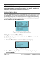
Setting the Terminal Date & Time
Use this function to set the date and time for the FPT-40 terminal with
the following procedure:
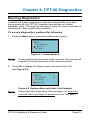
1. Press the Menu button and select Options (see figure).
Menu
User Manage
Options
Sys Info
Figure 2-87 Main Menu
2. Press OK to display the Options menu and select System Opt
(see Figure 2-88).
Page 2-34
FPT-40 Installation & Operation Guide
Options
System Opt
Power Mng
Comm Opt
Figure 2-88 Options Menu
3. Press OK to display the System Opt menu and select Date Time
(see Figure 2-89).
System Opt
Date Time
24H
Language
12H
ENG
Figure 2-89 Date/Time
4. Press OK to display the Date & Time (see Figure 2-90 for an
example). Press the down or up arrow buttons to move forward
or backward, one field per press. Use the numeric keypad to enter
the changes to the date and time values. Only allowable values for
each field will be accepted, i.e., 14 for month is not a valid value.
Figure 2-90 Date & Time Example
Note:
The date entry format is fixed as YYYY-MM-DD with a 24H
time format.
5. Press OK to save the settings, and return to the System Opt menu.
6. Keep pressing ESC to return to the Welcome screen, or just let the
terminal automatically default to the Welcome screen. From the
System Opt menu select Adv Option if changes to advanced options
are required.
FPT-40 Installation & Operation Guide
Page 2-35
Setting the Display Time Format
From the System Opt menu select Time Format, and then choose 24H
for military time, or 12H for AM/PM time format. The default time format
is 12H. The display time format can be set at the terminal or downloaded
from the Time & Attendance software, which should be set in the same
time format as the terminal.
Note:
This format does not change the time format of the FPT-40
terminal, as it only changes the terminal display format.
Setting the Language
1. From the System Opt menu select Language (see Figure 2-91).
System Opt
Date Time
Time Format
Language
12H
ENG
Figure 2-91 System Options Language
2. Press OK to highlight the current Language. Use the or buttons
to move between choices, which are; English or Spanish.
3. Press OK to save the selection, or press ESC to keep the default
selection; which is English. You must restart the terminal for the
selected language to take effect.
Setting the Display Date Format
The default display date format is MM/DD/YY.
1. From the System Opt menu select Fmt [format] (see Figure 2-91).
System Opt
Date Time
Language
Eng
Fmt
MM/DD/YY
Figure 2-92 Date Format
Page 2-36
FPT-40 Installation & Operation Guide
2. Press OK to highlight the display format setting. Use the or
buttons to select one of the formats, which are; YY-MM-DD,
YY/MM/DD, YY.MM.DD, MM-DD-YY, MM/DD/YY, MM.DD.YY, DDMM-YY, DD/MM/YY, DD.MM.YY, or YYYYMMDD.
3. Press OK to save the selection, or press ESC to keep the default.
Note:
This format does not change the date format of the FPT-40
terminal, as it only changes the terminal display format.
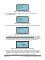
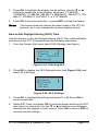
How to Set Daylight Saving (DLS) Time
Use this function to set the Daylight Saving (DLS) Time start/end dates
and times at the FPT-40 terminal with the following procedure:
1. From the System Opt menu select DLS Settings (see figure).
System Opt
Language
ENG
Fmt
MM-DD-YY
DLS Settings
Figure 2-93 Selecting DLS
2. Press OK to display the DLS Settings menu (see Figure 2-94) and
select DLS Settings.
DLS Settings
DLS Settings
DST Start
DST End
Y
Figure 2-94 DLS Settings
3. Press OK to highlight the setting and select Y or N. Press OK to
save the selection.
4. Select DST Start, and press OK to enter the begin date/time for DST
(see figure for example). Use the or buttons to move between
choices and the keypad to enter values. Press OK to save or ESC to
exit with default settings.
FPT-40 Installation & Operation Guide
Page 2-37
MM - DD
3 - 09
ESC
24H
2:00
OK
Figure 2-95 DST Start Date/Time
Note:
The DST Start and End time format is fixed as a 24H format.
5. Select DST End, and press OK to enter the end date/time for DST
(see figure for example). Use the or buttons to move between
choices and the keypad to enter values. Press OK to save or ESC to
exit with default settings.
MM - DD
10 - 02
ESC
24H
2:00
OK
Figure 2-96 DST End Date/Time
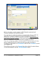
Note:
The FPT-40 Fingerprint terminal will utilize these settings to
adjust the terminal's future clock time based upon the DLS
date settings. However, the Time & Attendance software DLS
settings (see figure) will have precedent when the “Override
DLS” box is enabled [checked].
Figure 2-97 Time & Attendance Software DLS Settings
Page 2-38
FPT-40 Installation & Operation Guide
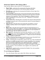
Advanced Options (Adv Option) Menu
Use the Adv Option menu at the FPT-40 terminal to:
Reset Opts.: selecting this command will restore all setup
information in the terminal to the factory default settings.
Del AttLogs: selecting this command will delete all user logs from
the flash memory.
Clear All Data: selecting this command will delete all enrolled user
information including templates, passwords and logs from the flash
memory of the terminal. The Time & Attendance software can be
used to restore this information from the "Fingerprint Commands"
(see page 3-12).
Clear Admin Pri: selecting this command will clear all administrative
privileges currently set in the terminal and reset all user privileges to
ordinary users.
Show Score: selecting this command will set whether or not to
display a quality value for the fingerprint template on the LCD
screen.
Match Thr: selecting this command sets the threshold level for a
one-to-many match, see Table 2-1. A one-to-many threshold is used
to compare the finger template to the database of user templates to
determine the user (ID) that just punched.
Mst Input ID: selecting this command sets whether or not [Y or N] if
you must enter your User ID when punching. When this command is
set to Y, all users are compared with a 1:1 match to their ID with their
finger template or password.
1:1 Thr: selecting this command sets the one-to-one threshold level
when comparing an ID to a fingerprint or password.
Voice: selecting this command is used to set (Y), so the terminal will
produce an audible prompt sound for every operation. For example,
after a successful verification, the machine will say ("Thank you"). If
the Voice is set to (N) the machine will not produce an audible
prompt, but instead just beep once to signify a sucessful verification.
In this instance, if the verification was negative, the machine will
beep twice.
Adj VOL(%): selecting this command will adjust the voice speaker
volume for audible prompts.
To set Advanced Options:
1. From the System Opt menu select Adv Option (see figure).
FPT-40 Installation & Operation Guide
Page 2-39
System Opt
Fmt
MM/DD/YY
DLS Settings
Adv Option
Figure 2-98 Select Adv Option Menu
2. Press OK to display the Adv Option menu (see Figure 2-99). Press
the “▲/▼” buttons to scroll up or down to select the desired option.
Adv Option
Reset Opts.
Del AttLogs
Clear All Data
Clr Admin Pri
Show Score
Match Thr
Mst Input ID
1:1 Thr
Voice
Adj VOL (%)
N
35
Y
15
N
67
Figure 2-99 Adv Option Menu
2. For Adv Options such as; Match Thr, 1:1 Thr, and Adj VOL(%), use
the numeric keypad or “▲/▼” to enter the desired value.
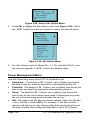
Power Management Menu
Use the Power Mng menu at the FPT-40 terminal to set:
Shutdown.: The default is "N". If active, set in military time format
the time of day you want the terminal to automatically power off.
PowerOn: The default is "N". If active, set in military time format the
time of day you want the terminal to automatically power on.
Sleep: The default is "N". If active, set in military time format the
time of day for the unit to enter sleep mode. Pressing any key once
the unit enters the sleep mode will wake the unit up.
Idle: This option and Idle Min are directly related. When the Idle Min
= zero, the Idle = closed [SLP]. For example, if Idle Min is set to 1
minute, and there is no user activity within that minute, then the unit
will enter the idle state (sleep) provided Idle is set to SLP [sleep].
Page 2-40
FPT-40 Installation & Operation Guide
However, if Idle is set to OFF, then the terminal will power off when
the idle min is reached.
Idle Min: The default is "0". See previous.
Lock Power: The default is "N". If this option is set to "Y", when the
power On/Off button is pressed nothing will happen as this button will
be locked out.
To set Power Mng Options:
1. Press the Menu button and select Options (see figure).
Menu
User Manage
Options
Sys Info
Figure 2-100 Select Options
2. Press OK to display Options menu and select Power Mng
(see Figure 2-101).
Options
System Opt
Power Mng
Comm Opt
Figure 2-101 Select Power Management
3. Press OK to display the Power Mng menu (see Figure 2-102).
Power Mng
Shutdown
PowerOn
Sleep
N
N
N
Idle
Idle Min
Lock Power
SLP
0
N
Figure 2-102 Power Management Menu
FPT-40 Installation & Operation Guide
Page 2-41
4. Press “▲/▼” to scroll up or down the screen to select the desired
option. For Power Management options Idle & Lock Power, press
OK and use “▲/▼” to enter the desired state. For all other power
management options, press OK and use the numeric keypad and/or
“▲/▼” to enter the desired value (see figure for example). For all
power management options, pressing ESC will return the default
value/state, and exit to the Power Mng menu.
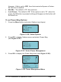
Follow this example to set the shutdown time:
1. Press OK from the Power Mng menu, with Shutdown selected
(see figure).
Power Mng
Shutdown
PowerOn
Sleep
N
N
N
Figure 2-103 Select Shutdown Time
2. Press OK to enter shutdown time of day in 24 hour format (see
Figure 2-104). Use “▲/▼” to move between hours and minutes and
the keypad to enter time.
Power Mng
Shutdown
PowerOn
Sleep
23 : 59
N
N
Figure 2-104 Shutdown Screen
3. Once the desired shutdown time of day in 24H format is set, press
OK to exit and display the Power Mng menu (see Figure 2-102).
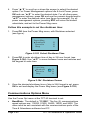
Communications Options Menu
Use the Comm Opt menu at the FPT-40 terminal to set:
BaudRate: The default is "115200". The five (5) communications
speed options are; 115200, 57600, 38400, 19200, and 9600. The
value must be set consistent with the communications ports of the
Time & Attendance software host PC.
Page 2-42
FPT-40 Installation & Operation Guide
Dev Num: The default is "1". The range is 1 to 255. The device
number is unique for each terminal. If there are two terminals with
the same number in the network, they will not work properly and
Time & Attendance software will be confused when polling the
terminals.
IP Addr: The default is "192.168.1.201". The IP address for the
terminal must be unique in the LAN.
Net Speed: The network default speed is "AUTO". The other
choices are: 10M-H, 100M-H, 10M-F and 100M-F.
Net Mask: The default is "255.255.255.0". The subnet mask must
be consistent to the LAN IP address of the device.
Gateway: The default is "0.0.0.0". If Gateway and Net Mask are not
defined, Ethernet will not be active.
Ethernet: select "Y" or "N" for Ethernet TCP/IP communications.
This option must be set to (Y)es to utilize Ethernet.
RS232: select "Y" or "N" for RS232 serial communications.
RS485: select "Y" or "N" for RS485 serial communications
[used for transmission distances over 50 feet].
COMM Key: The default is "0". The range is 1 to 999999. This
function is not used.
To set communication options:
1. Press the Menu button and select Options (see figure).
Menu
User Manage
Options
Sys Info
Figure 2-105 Select Options
2. Press OK to display Options menu and select Comm Opt
(see Figure 2-106).
Options
System Opt
Power Mng
Comm Opt
Figure 2-106 Select Comm Opt
FPT-40 Installation & Operation Guide
Page 2-43
3. Press OK to display the Comm Opt menu (see Figure 2-107).
Comm Opt
BaudRate
Dev Num
IP Addr
Net Speed
NewMask
Gateway
Ethernet
RS232
Rs485
COMM Key
115200
1
N
AUTO
Y
Y
N
0
Figure 2-107 Comm Opt Menu
4. Press “▲/▼” to scroll up or down to select the desired option. Press
OK and use the numeric keypad and/or “▲/▼” to enter the desired
value. For all Comm options, pressing ESC will return to the Comm
Opt menu with the default value/state.
Follow this example to enter the IP Address:
1. From the Comm Opt menu, select IP Addr [IP address] (see figure)
and press OK.
Comm Opt
BaudRate
Dev Num
IP Addr
115200
1
Figure 2-108 Comm Opt Menu – IP Addr
2. Enter the desired IP address (see Figure 2-109) by using “▲/▼” to
move forward or backward and the keypad to enter a number.
IP Addr
192. 168. 1. 201
ESC
1
OK
Figure 2-109 Enter IP Address
Page 2-44
FPT-40 Installation & Operation Guide
3. Once the correct IP address is entered, press OK to save, or ESC to
exit with the default IP address [192.168.1.201].
Log Options Menu
Use the Log Opt menu at the terminal to:
Alm SuperLog: The default is "99". The range is 0 to 99. When the
supervisor capacity log numerical value is reached, an alarm will
sound to automatically indicate that the logs are full.
Alm AttLog: The default is "99". The range is 0 to 99. When the
attendance log capacity numerical value is reached, an alarm will
sound to automatically indicate that the logs are full.
ReCheck Min: The default is "0". Each unit = a minute, i.e., 2 = 2
minutes. This feature is dissabled when set to 0. Recommended
setting is 1 or 2 minutes. This feature provides repunch protection.
For example, when set to 1 minute, if an employee punches multiple
times at the terminal within the 1 minute, only the first punch will be
recorded in flash memory. All verified additional punches within the
ReCheck Min setting will be follwed by the voice prompt, "Punch
accepted….thank you".
To set Log Options:
1. Press the Menu button and select Options (see figure).
Menu
User Manage
Options
Sys Info
Figure 2-110 Select Options
2. Press OK to display the Options menu and select Log Options
(see Figure 2-111).
Options
Power Mng
Comm Opt
Log Opt
Figure 2-111 Select Log Opt Menu
FPT-40 Installation & Operation Guide
Page 2-45
3. Press OK to display the Log Opt menu (see Figure 2-112).
Log Opt
Alm SuperLog
Alm AttLog
ReCheck Min
99
99
0
Figure 2-112 Log Options Menu
4. Select the desired option. For log options, press OK and use the
numeric keypad and/or “▲/▼” to enter/select the desired value (see
figure for example). For all Log options, pressing ESC will return to
the default value/state and exit to the Log Opt menu.
Follow this example to enter the ReCheck Min:
1. From the Log Opt menu, select ReCheck Min (see figure), and press
OK.
Log Opt
Alm SuperLog
Alm AttLog
ReCheck Min
99
99
0
Figure 2-113 Log Opt Menu – ReCheck Min
2. Enter the ReCheck Min time (see Figure 2-113) by using the “▲/▼”
buttons or the keypad to move between minutes [the range is 0 to
99] for time entry.
3. Once the desired ReCheck Min is set, press OK to save and return
to the Log Opt menu.
Auto Test
This option is designed to run assorted tests on the unit to analyze a
failure for quick and easy maintenance. These tests check such things
as the memory, LCD display, sound, fingerprint sensor, keypad, and
clock. During these tests the power should be maintained to prevent any
hardware damage; especially during the memory test. See Running
Diagnostics on page 4-1 for additional information and operational
details.
Page 2-46
FPT-40 Installation & Operation Guide
Note:
if any users have been setup with privileges, you must be a user
with Admin privileges to have access to the Auto Test menu.
Sys Info Menu
This menu can be used to display the following system information:
User Cnt: Displays the total amount of users stored in the terminal.
FP Cnt: Displays the total number of fingerprint templates stored in
the terminal.
Att Log: Displays the total number of punches [attendance] stored in
the terminal.
Admin Cnt: Displays the total number of administrators stored in the
terminal.
Pwd Usr: Displays the total number of users stored in the terminal
who are using a password for authentication.
S Logs: Displays the total number of system logs that have
occurred. Everytime anything is changed at the terminal it is added in
this log. For example, this could include just pressing the MENU
button.
Free Space Info: Press OK to display the following Free Space Info
menu to show the remainder of the log capacity:
FP Cnt – Displays the remaining capacity for fingerprint
templates to be stored in flash memory at the terminal.
Att Log – Displays the remaining capacity for attendance
(punches) to be stored in flash memory at the terminal..
S Logs– Displays the remaining capacity for system logs to be
stored in flash memory at the terminal.
Dev Info: Press OK to display the following device information for
the terminal:
FPCnt (100) – Displays the total fingerprint template capacity
[1500].
AttLog (10K) – Displays the total attendance (punches) capacity
[30,000].
S Logs– Displays the total capacity of system log capacity
[4096].
FPT-40 Installation & Operation Guide
Page 2-47
Manu Time– Press OK to display the date and time the terminal
was manufactured. Press OK or ESC to return to Dev Info menu.
Serial Num– Press OK to display the terminal serial number.
Press OK or ESC to return to Dev Info menu.
Vendor– Not operational. Press OK or ESC to return to Dev Info
menu.
Device Name– Not operational. Press OK or ESC to return to
Dev Info menu.
Alg Version– Press OK to display the algorithm version. Press
OK or ESC to return to Dev Info menu.
Firmware Ver– Press OK to display the firmware version and
release date. Press OK or ESC to return to Dev Info menu.
To display system information:
1. Press the Menu button and select Sys Info (see figure).
Menu
User Manage
Options
Sys Info
Figure 2-114 Select Sys Info
2. Press OK to display the Sys Info menu (see Figure 2-115).
Sys Info
User Cnt
FP Cnt
Att Log
Admin Cnt
Pwd Usr
S Logs
Free Space Info
Dev Info
2
2
0
0
0
58
Figure 2-115 System Information Menu
3. Press the “▲/▼” buttons to select/view the desired system info. For
Free Space and Dev info, press OK to view additional information.
Page 2-48
FPT-40 Installation & Operation Guide
Chapter 3: FPT-40 Setup with Time &
Attendance Software
See the Time & Attendance User's Guide [AMX-406700] for more
detailed operation and setup information for the Time & Attendance
software.
FPT-40 Terminal Communications
The Communications module in the Time & Attendance software can
be used to communicate with FPT-40 terminals when setup. Locations
and terminals can be configured utilizing the Time & Attendance software
Clock tab in the Setup Wizard. Operations from this module include
polling, downloading, setting the time, and viewing specific terminal
settings in a location. Polling, or polled operation, refers to actively
sampling the status of the external terminals by the client Time &
Attendance program. Downloading is utilized to send data to the remote
terminals from the Time & Attendance software.
Note:
All operations at the clock including time and employee ID’s
are controlled by downloading information from the Time &
Attendance software.
The following sections describe how to setup the Amano Time &
Attendance Software to communicate with the FPT-40 terminal for
normal time and attendance functions.
FPT-40 Setup with Amano Time & Attendance Software
Note:
Prior to commencing with the Time & Attendance software
Setup Wizard, Amano recommends that you install the FPT-40
terminal(s), using this FPT-40 Terminal Installation and
Operation Guide. The FPT-40 terminal is installed to
communicate with your PC.
If you are setting up a networked Ethernet FPT-40 terminal,
you may need to obtain the correct IP address from your
network administrator for each Ethernet FPT-40 terminal(s)
connected to the system and enter the IP address in the
Location screen of the Time & Attendance software. Also, see
the section on “Communications Options Menu” for how to
enter a specific IP into your FPT-40 terminal.
FPT-40 Installation & Operation Guide
Page 3-1
During the installation and setup of the Time & Attendance software the
Setup Wizard for Step 8: Clock Setup should be used to setup your
FPT-40 terminal;
Figure 3-1 Clock Setup from Time & Attendance Software
Use Step 8 if:
Do you have Terminals other than Access Control Terminals?
If Yes, the Time & Attendance software will automatically poll and upload
punches from connected FPT-40 terminals each time the software is
opened.
If No, the connected FPT-40 terminals will have to be polled manually
using the Communications module in the Time & Attendance software.
Do you want to configure Terminal Validation?
If Yes is selected for Terminal Validation, click the Terminal Validation
button and the Terminal Validation screen will appear (see Figure 3-2).
Terminal validation provides employee filtering from the setup configured
in the General, Department, and Employee tabs in the Time &
Attendance software.
Page 3-2
FPT-40 Installation & Operation Guide
Terminal Validation is used to assign employees and Labor Levels to
specific FPT-40 terminals in the system. When validation is used, only
employees assigned to a particular terminal with the selected Labor
Levels can use that terminal. Labor transfers at the terminal can only
occur within the selected Labor Levels. Terminal Validations are
downloaded to the selected FPT-40 terminals by location from the
Communications module. To do so, see the Time & Attendance Software
User Guide for more detailed information:
Figure 3-2 Software Setup for Terminal Validation
Do you want to configure Bell Schedules?
If Yes is selected for Bell Schedules, click the Bell Schedule button for
the Bell Schedules screen (see Figure 3-3).
Figure 3-3 Software Setup for Bell Schedules
FPT-40 Installation & Operation Guide
Page 3-3
Special Note:
Selecting Holidays will only work with HandPunches
(all HandPunch models).
The FPT-40 terminal does not contain the capability to
ring bells, but you may have a configuration which
includes other terminals such as the MTX-15 or
HandPunch that does have relays for bell ringing.
A Bell schedule requires you to enter the Duration for the bell to ring, the
time of day for the bell to ring and the days of the week. Multiple entries
can be made for Bell Schedules with different duration and day
assignments. Bell Schedules are downloaded to the selected terminals
by location by using the Communications module in the Time &
Attendance Software. To do so, see the next section and/or Time &
Attendance Software User Guide for more details.
Do you want to configure Terminals?
Answer Yes to this question if you are using terminals such as a FPT-40
terminal via a serial (driect) or Ethernet (network) connection.
Direct (serial) Connection
If Yes is selected, and a Direct connection using the included 50 foot
USB/serial cable is desired, you can just use the “FPT-40 Default”
location. You do not have to do anything else. The FPT-40 terminal, if
connected, will automatically be detected upon login.
Note:
The default terminal connection is for a USB (serial-direct)
FPT-40 Terminal.
Ethernet (network) Connection
If Yes is selected, and you are installing an Ethernet connection for the
FPT-40 click on the Location/Terminal
(see Figure 3-1) and the Locations screen will appear.
button
Select “FPT-40 Default” on the General tab from the dropdown
menu for Locations [recommended for easy configuration].
Click on Connection tab to select Ethernet for Connection Type and
enter your IP Address. The default FPT-40 Location automatically
defines everything else for Ethernet. Click on
Page 3-4
button.
FPT-40 Installation & Operation Guide
Figure 3-4 Software Setup for Locations
Before a Location can be created, a Bell Schedule (optional) and
Terminal Validation list should be setup.
You may have to create a Location to communicate with your FPT-40
terminals. A Location enables the Time & Attendance software to
distinguish and interact with the desired terminal(s). Only one terminal
type can be used per Location. If you have more than one terminal type
[i.e, FPT-40 and MTX-15], you must have multiple Locations.
If you are configuring a direct connect serial FPT-40 terminal, you may
have to determine the PC Comm port that the USB CommStik is
connected to and select it in Connection tab from the Locations screen
(see Figure 3-5).
The window will open on the General tab with a default Location Name.
It is recommended to use the “FPT-40 Default” name.
FPT-40 Installation & Operation Guide
Page 3-5
To create a new Location in Time & Attendance software for
FPT-40 terminal:
Step 1. Click the Add
button to create a new Location. You will be
required to enter a unique Name [yellow required field] that will
be used to describe the area or site where a terminal or group
of terminals is located.
Step 2. In the Description field, enter a brief description of the
Location. This field is optional.
Step 3. In the Term Type field; select FPT-40.
Step 4. In the TZ (Time Zone) Offset field, select the time zone
difference (if applicable) between the physical location of your
PC and the FPT-40 terminals.
Step 5. In the Output Path field, enter the path of the output XML file.
If necessary, press the Browse button to navigate to the
location of the XML output file.
Step 6. If necessary, check the “Secondary Output File” box, and In
the Output Path field, enter the path of the secondary output
file. Press the Browse button to navigate to the location of the
secondary output file.
Step 7. Click on the Override DLS for DLS (Daylight Savings Time )
Settings override and enter the following:
Start Date: The date that the DLS period will begin.
Start Time: The time of the day of the Start Date that the
DLS period will begin.
End Date: The date that the DLS period will end.
End Time: The time of the day of the End Date that the
DLS period will end.
Press the Reset button to Reset the DLS at the Terminal.
Step 8. From the Locations screen click on the Connection tab.
Page 3-6
FPT-40 Installation & Operation Guide
Figure 3-5 Software Setup for Connection Type
Step 9. In the Connection field, select the type of connection you are
using to communicate with the FPT-40 terminal(s). The
required information in the Connection Info depends on your
connection.
Note:
Ethernet: The FPT-40 terminals communicate to the Host
PC via Ethernet connection. If selected, you must enter the
IP Address and Port 4370. [Obtain the correct IP address
from your network administrator, or alternatively, please
consult Chapter 3: Network Configuration of this Guide for
additional information about hardware configuration].
The Port number for Ethernet terminals must be set to;
MTX-15 = 2101, MTX-10 & 20 = 401, FPT-40 = 4370, and
HandPunch’s = 3001.
Direct: The FPT-40 terminal(s) are directly connected to
the Host PC via Com Port. If selected, you must select the
Com Port and Baud Rate.
Step 10. Click on the Terminals tab to add, edit, delete, or
communicate with FPT-40 terminals.
FPT-40 Installation & Operation Guide
Page 3-7
Figure 3-6 Setup for Locations with Terminals Tab
Step 11. The Ethernet and direct connection FPT-40 terminals in this
location should appear in the Terminals list (see figure).
Step 12. Double-click on the found terminal or highlight the terminal and
click on the Add button to add a new Terminal to the Location
and the Terminal window General tab will appear for setup.
Figure 3-7 Software General Terminal Setup
Step 13. In the Name field, enter in a unique name [required field] that
will be used to describe the terminal. This field will be
automatically populated with the MAC address when the
eyeglass button is used.
Page 3-8
FPT-40 Installation & Operation Guide
Step 14. In the Number field, enter in a unique number for the terminal
if allowed.
Step 15. In the Serial No. field, a unique number will appear for a found
FPT-40 terminal.
Step 16. This capability not available on FPT-40 so the selection is
grayed out.
Step 17. If you wish to assign a Terminal Validation setting to the
terminal, select one from the dropdown list in the Validation
field.
Step 18. Click on the Options tab to activate the Coffee, Break, and
Meal punch templates at the FPT-40 terminal with a check.
The labor button is greyed out because this function is not
available at the terminal.
Step 19. In the Time Format box, select the time format (12-hour or 24hour) for the terminal.
Figure 3-8 Software Terminal Options Setup
Step 20. In the Misc box, select whether to enable the view hours for
the current pay period at the terminal.
FPT-40 Installation & Operation Guide
Page 3-9
Step 21. To update the terminal settings, click on the Apply button. This
will download the current settings in this window to the
terminal.
Time & Attendance Software Communications Module
With the Time & Attendance Software open on the host PC, from the tree
view, click on the Communications module within the Daily Activities
group and the following type of screen should appear for the Time
Guardian Plus. Note – the tree view can look a little different depending
upon which modules are activated and/or whether it is Time Guardian
Pro (all modules will be active). The figure below shows the tree view for
Time Guradian with all modules activated.
Figure 3-9: Time & Attendance Software Tree View
Locations are selected by clicking on the desired row (see highlighted
example in Figure 3-9). You can select multiple locations by holding
down the Ctrl Key and clicking on other locations. Also, you can sort the
displayed Locations list by clicking on the dropdown list in the upper lefthand corner and selecting on; Name, Description, Term Type, TZ Offset,
Connection, IP, Port, COM Port, Baud Rate, Modem, and Phone. Once
the location is selected use the following commands found at the bottom
of the screen to communicate with the connected FPT-40 terminal(s) at
that location:
Page 3-10
FPT-40 Installation & Operation Guide
To select specific terminals within a location, double-click on the desired
location row, and the following Communications dialog will appear:
Figure 3-10: Software Communications Screen
Select terminals in the Terminals list by placing a check in the Select box
of each terminal. When you have finished making your selections, use
one the commands to communicate with the FPT-40 terminals.
FPT-40 Installation & Operation Guide
Page 3-11
Using the Fingerprint Commands
From the Time & Attendance software Communication Settings screen,
this tab allows you to perform the following functions with the FPT-40
Fingerprint terminal:
button to collect the most recent data from the
Poll: Press the
terminal(s) (i.e., fingerprint templates and punches). When checked,
Time Sync. performs time synchronization between the Host PC and
the terminal(s) including Daylight Saving settings.
button to send time, Daylight Saving
Download: Press the
Time settings, hours worked for the current pay period, and
employee assignments. The hours worked will be retained at the
terminal from the date of the last download for up to 14 days. If no
new download occurs within 14 days, the hours worked will not
appear after 14 days.
Note:
When this button is pressed, the terminal display will show
Downloading…., followed by Working…., and finish with
Restarting…..The terminal will power off then back on to
refresh with the options just downloaded to it. Simultaneously
the lower portion of the Time Guardian Fingerprint Commands
screen will display the location, terminal # downloaded
date/time, hours worked sent for users X to Y, time format
changes, restarting device, and download operation done (see
figure). Click on Clear Display to clear the displayed information.
Biometric Maps: The terminal must be polled before performing the
following operations. Polling the terminals will save biometric fingerprint
templates for newly enrolled employees, automatically update the
database with templates for employees who have punched at the
terminal, and create terminal assignments for employees that have not
yet been enrolled in the database.
Note:
If a newly enrolled employee does not exist in the employee
database, then the template in the terminal will not be saved. If
the template data is inadvertently lost, it must be reassigned to
the terminal through the Assignments tab.
Page 3-12
FPT-40 Installation & Operation Guide
Each time an employee punches at the FPT-40 Fingerprint terminal,
their finger template (map) will automatically be updated in the employee
database with the most recent template from the terminal. This feature is
for maintaining accurate fingerprint templates. However, if the employee
does not exist in the employee database, then a message will be
displayed in the message window at the bottom of the tab.
Once an employee is added to the Employee database, their template
will not automatically be uploaded unless the employee is removed and
re-enrolled at the terminal, or a punch is received from the terminal.
Once this is done, however, the employee’s template will be saved and
an assignment will automatically be created.
button to send user(s) biometric
Send Maps: Press the
map(s) from the employee database in Time Guardian to the
selected terminals. Only employees assigned to terminals will be
sent. Employees are assigned to terminals from the Assignments
tab, or by polling. Because the “Send Maps” operation consists of
first clearing all templates from the terminal and then loading
assigned employee templates.
button to receive employee
Receive Maps: Press the
templates from the selected terminal(s) to the Time Guardian
database. Only templates assigned to the selected terminals will be
uploaded to TG. Employees are manually assigned to the terminals
in the Assignments tab.
button to clear (delete) all assigned
Clear Maps: Press the
employee templates from the terminal. Because the Clear Maps
operation consists of clearing all templates from the terminal, a
confirmation dialog box will appear before this command executes.
Caution!
This command can be used to clear [reset] the terminal
if an Administrator has been setup and the password is
lost, etc. Access at the terminal to the menu options,
etc. maybe denied unless it is an Administrator.
FPT-40 Installation & Operation Guide
Page 3-13
Note:
All the above command options can be performed at either
Selected Terminals, All Terminals, or All Locations. Whereas,
the "Polling" and "Downloading" commands from the
Communication menu can only be performed on
All Terminals at All Locations.
Page 3-14
FPT-40 Installation & Operation Guide
Chapter 4: FPT-40 Diagnostics
Running Diagnostics
In addition to system diagnostics which run automatically every time
during power up, the FPT-40 Fingerprint terminal has an internal
diagnostic utility. This utility can be used to verify the correct operation of
the terminal to help isolate faulty operation.
To access diagnostics, perform the following:
1. Press the Menu button and select Options (see figure).
Menu
User Manage
Options
Sys Info
Figure 4-1 Select Options
Note:
If no keypad entries are made within a minute, the terminal will
beep two (2) times and return to the Welcome screen.
2. Press OK to display the Options menu and select Auto Test
(see Figure 4-2).
Options
Comm Opt
Log Opt
Auto Test
Figure 4-2 Options Menu with Auto Test Selected
Note:
If any users have been setup with privileges, you must be a
user with Admin privileges to access the Auto Test menu.
FPT-40 Installation & Operation Guide
Page 4-1
3. Press OK to display the Auto Test menu (see Figure 4-3).
Auto Test
Run All Test
FLASH Test
LCD Test
Figure 4-3 Auto Test Menu
4. Use the down or up arrow buttons to select the desired test,
and press OK to run that test (see Figure 4-4 for an example of LCD
test).
WWWWWWWWWWW
WWWWWWWWWWW
WWWWWWWWWWW
WWWWWWWWWWW
Figure 4-4 LCD Test Screen
5. Follow the on screen prompts. All the tests, except the LCD test,
require you to press ESC or OK at their completion. The LCD test
requires that you press OK to step through each phase of the test.
Run All Test
Select this test to run all six of the built-in diagnostic tests in the following
order; FLASH Test, LCD Test, Voice Test, FP Reader, Key Test, and
RTC Test. At the completion of each test press OK to move to the next
test or press ESC to abort testing and return to the Auto Test menu.
Auto Test
Run All Test
FLASH Test
LCD Test
Figure 4-5 Run All Tests
Page 4-2
FPT-40 Installation & Operation Guide
FLASH Test
This will test the flash memory in the FPT-40 Fingerprint terminal and
indicate the functional status. Select the FLASH test, and press OK to
run (see figure).
Note:
Once this test is started do not interrupt the power as this
could cause damage to the internal flash memory.
FLASH Test
Pls Keep Pwr On
Continue?
ESC
OK
Figure 4-6 FLASH Test
The test will display Finished! if the flash memory is good (see figure).
FLASH Test
Finished !
All : 31 Bad : 0
ESC
OK
Figure 4-7 FLASH Test Finished
Press OK or press ESC to return to the Auto Test menu.
LCD Test
This diagnostic tests the display by turning on all the pixels. Any spots
would indicate a defective pixel.
Press OK to complete each phase of the test, or press ESC to exit the
test and return to the Auto Test menu.
FPT-40 Installation & Operation Guide
Page 4-3
Voice Test
This will test the voice prompts stored in the FPT-40 Fingerprint terminal.
Press OK to play the selected voice prompt (see figure).
Voice Test
Play Voice 1.
ESC
OK
Figure 4-8 Voice Test 1
Press OK to perform each of the 10 voice tests, or press ESC to exit the
test and return to the Auto Test menu. The voice test responses are:
Voice 1 = "Thank you"
Voice 2 = "Incorrect password"
Voice 3 = "Access denied"
Voice 4 = "Invalid ID"
Voice 5 = "Please try again"
Voice 6 = "Re-enter ID"
Voice 7 = "The clock is full"
Voice 8 = "The clock is full"
Voice 9 = "Duplicate finger"
Voice 10 = "Punch accepted, thank you"
FP Reader Test
This will test the FP reader in the FPT-40 Fingerprint terminal and
indicate the functional status. Select FP Reader test, and press OK to
perform test. The test will display OK! if the reader status is operational
(see figure). Press OK or press ESC to return to the Auto Test menu.
FP Reader
OK !
ESC
OK
Figure 4-9 FP Reader OK
Page 4-4
FPT-40 Installation & Operation Guide
Key Test
Once the Key Test has started, pressing any numeric key will display the
number on the highlighted test line (see figure). MENU will indicate
“MENU” and or will display “UP” or "DOWN". Press OK or press
ESC to return to the Auto Test menu.
Key Test
Press Any Key
NUM: 7
ESC
OK
Figure 4-10 Key Test Example
RTC Test
This will test the Real Time Clock in the FPT-40 Fingerprint terminal and
indicate the functional status. Press OK to perform test. The test will
display OK! if the RTC status is operational (see figure). Press OK or
press ESC to return to the Auto Test menu.
RTC Test
OK!
ESC
OK
Figure 4-11 RTC Test Ok
Frequently Asked Questions (FAQs)
1. Q: Some user's fingerprints occasionally cannot be verified?
A: The following reasons could lead to a poor fingerprint template:
Smooth fingerprint
The fingerprint contains too many drapes [ridges] and/or
they change too often
The fingerprint in question has serious skin shed
Resolution: Select a different fingerprint (less crinkle, no
sloughed off skin, clear image), and make your fingerprint touch
a larger area of the sensor. Also, enroll more than 1 fingerprint,
and use 1:1 match method with password verification method.
FPT-40 Installation & Operation Guide
Page 4-5
2. Q: FPT-40 Fingerprint terminal(s) fail to communicate?
A: The following reasons could lead to faulty communications:
COM port configuration is not correct. COM port currently
selected is not the actual COM port being used.
The Baud rate settings between the fingerprint reader and
the PC COM port are different
The fingerprint reader has failed to connect with the
computer.
The fingerprint reader has connected but it is not starting up.
The serial number of linked fingerprint reader is not correct.
The Data line or converter (CommStik) fails to communicate.
The PC COM port breaks down.
3. Q: Upon power up, the FPT-40 Fingerprint terminal LCD
displays incompletely; only half, sometimes jumbled, etc?
A: The possible reasons are:
Bad motherboard in fingerprint terminal.
Bad LCD display, seek service/repair/replacement.
4. Q: How to clear administrator from the FPT-40 terminal?
A: The following method could be used:
From the FPT-40 Fingerprint terminal clear the Administrator
privileges utilizing the "Clr Admin Pri" [clear administrator
privileges] command from the Adv Option menu. However, if you
cannot gain access to do this, you must use the "Clear Maps"
command from the Time & Attendance software. See Using the
Fingerprint Commands.
From the Fingerprint terminal follow this procedure:
Step 1. Press the MENU button.
Step 2. Enter administrator User ID.
Step 3. Press OK, and enter password or press enrolled finger.
Step 4. Select Options menu with arrow keys, and press OK.
Step 5. From Options menu select System Opt, and press OK.
Page 4-6
FPT-40 Installation & Operation Guide
Step 6. From System Opt menu select Adv Option menu, and
press OK.
Step 7. Select Clr Admin Pri, and press OK.
Step 8. Press OK again to confirm, and reset Admin.
Note:
Only an administrator will have access to the Adv Opt menu to
reset the privileges. When setting up privileges, always setup an
Admin first before setting up a Supervisor and Enroller. Failure to
do so could result in not being able to get to the menu options for
additional setup changes.
5. Q: When the fingerprint terminal connects serially, and the
sound "ding, ding" occurs?
A: The possible reasons are:
With RS-232 communications, the computer Baud rate may
not match the terminal setting.
With RS-485 communication, two lines of the converter may
be joined.
6. Q: After fingerprint terminal power up, display always shows
"Please try again"?
A: The following reasons could lead to fingerprint sensor problems:
After a lot of use the surface of the fingerprint sensor
becomes dirty, or there are some scratches on it, so the
machine thinks that it is a fingerprint and tried to identify it.
Clean sensor surface [see Cleaning or Replacing the Optical
Sensor].
The fingerprint sensor cable may be loose, or possible
problem on the circuit PCB. Contact support for service.
FPT-40 Installation & Operation Guide
Page 4-7
Maintenance
Note:
Do not attempt to service the fingerprint reader unless you are a
trained service technician.
Cleaning
Occasionally, the surface of the optical sensor, the keypad and display
window may require cleaning. Since working environments differ, it is not
possible to define when cleaning should be performed, but the following
is a suggested guide.
Item
Keypad and display window
Cleaning Frequency
Clean when visibly dirty and hard to read.
See cleaning procedure.
Do not over clean. The sensor is designed
to work under greasy or dirty conditions.
Optical Sensor
Clean if the sensor performance has
degraded to where people are reporting
recognition problems. See cleaning
procedure.
Cleaning the Keypad and Display
To clean the keypad and display use a soft cloth to wipe.
Cleaning the Optical Sensor
To clean the optical sensor:
1. If dusty or gritty, first blow on the sensor surface to clean off loose
particles.
2. Use adhesive tape to clean the surface.
3. Use a non-abrasive soft dry cloth to wipe the sensor surface. Be
careful not to scratch the sensor surface with loose particles (see
Step 1).
CAUTION: Do not use any cleaning solutions, as this could damage the
optical sensor. Also, cleaning solvents that contain alcohol or
other strong substances may discolor or crack the fingerprint
reader cabinet.
Page 4-8
FPT-40 Installation & Operation Guide
Replacing Optical Sensor Lens
To replace the optical sensor lens:
1. If optical sensor lens becomes damaged (scratched) and cannot be
cleaned, replacement may be necessary.
2. Use the replacement [spare] optical sensor lens included with the
terminal. Remove the spare sensor lens from the protective
packaging (see figure), using care not to touch the prism.
Prism
4-12 Spare Prism & Packaging
3. Disconnect the AC Power Adapter from the bottom of the terminal.
4. Disconnect the communication cable (either Ethernet or serial DB9
connector)
5. Loosen and remove the four (4) back plate retaining screws and
remove the terminal from the wall mounted back plate.
6. Place the terminal on a soft surface face down. Located and remove
the four (4) Phillips Head screws holding the case front cover. There
will be one screw in each corner on the back of the case.
7. After removing the screws, place the terminal right-side up on the
back of the case and VERY CAREFULLY lift the front cover up.
8. The sensor housing must be removed by unscrewing the four (4)
Phillips head screws holding it down to access the optical sensor
lens (see figure).
FPT-40 Installation & Operation Guide
Page 4-9
9. Loosen and remove the four (4) Phillips head screws holding the
sensor/prism housing to access the sensor prism and replace. Use
CAUTION not to break any of the ribbon cables. Also, the
replacement prism must be mounted with the soft side facing
outward.
Prism Housing
10. Replace the sensor lens with the new spare, and perform the reverse
procedure to re-install the sensor housing, screw the back case on,
and remount the terminal to the wall bracket.
11. Reconnect the communication cable, and Power Adapter connector.
Note:
It is recommended that the above procedure be performed by
someone with electronics knowledge.
Page 4-10
FPT-40 Installation & Operation Guide
FPT-40 Specifications
Sophisticated algorithms provide dependable and accurate
identification speed to process fingerprints within 2 seconds.
A built in embedded standalone module (ZEM100) with robust Intel
32-bit X-scale CPU.
Supports 360-degree finger rotation for easy-to-use identification.
Sensor window design improves image quality, while accepting dry,
or wet fingers.
CMOS automated exposure and intelligent compensation provides
improved image quality.
Adjusts for image distortion to assure fingerprint matching
consistency.
Operating Environment:
32°F to 105°F (0°C to 42°C) with
20 - 80% relative humidity, non-condensing.
AC Adapter Power Input:
100 - 240 VAC 10%, 50-60 Hz
AC Adapter Power Output:
DC 5V 2A
Dimensions:
7.90." L X 5.35" W X 1.96" D
(200 mm L X 136 mm W X 50 mm D)
Weight:
1.35 lbs. (0.61 kg)
Daylight Saving Time (DST):
Settings are programmable at the terminal
and/or through Time Guardian software.
User Capacity:
1500
Transaction Storage:
30000
Verification Method:
Fingerprint, Password, Fingerprint + Password.
Verification Mode:
1:N
Verification Time:
1 second
Identification Time:
2 seconds
Enrollment Time:
5 seconds
False Acceptance Rate (FAR): 0.001%
False Rejection Rate (FRR):
1%
FPT-40 Installation & Operation Guide
Page 4-11
Specifications (Cont.)
Communication:
Ethernet: 10 Base-T/100 Base-TX (TCP/IP)
RS-485, or RS-232C
Communication Speed:
38400/19200/9600 BPS, TCP/IP: 10M
Memory Backup:
Provides up to 3 years of continuous memory
backup without AC power.
Display:
2.8” diagonal, 128 x 64 dots resolution LCD
reflective (backlight).
Keypad:
4x4 keypad (0~9, OK, ESC) + 4 function keys.
Clock:
Quartz oscillator, accuracy within 3 seconds
per week at normal temperature.
* Specifications and/or operational characteristics are subject to change without notice. The
AC adapter is UL listed E215890.
Page 4-12
FPT-40 Installation & Operation Guide
Note: This equipment has been tested and found to comply with the
limits for a Class B digital device, pursuant to Part 15 of the FCC Rules.
These limits are designed to provide reasonable protection against
harmful interference in a residential installation. This equipment
generates, uses and can radiate radio frequency energy and, if not
installed and used in accordance with the instructions, may cause
harmful interference to radio communications. However, there is no
guarantee that interference will not occur in a particular installation. If this
equipment does cause harmful interference to radio or television
reception, which can be determined by turning the equipment off and on,
the user is encouraged to try to correct the interference by one or more
of the following measures: Reorient or relocate the receiving antenna;
Increase the separation between the equipment and receiver; Connect
the equipment into an outlet on a circuit different from that to which the
receiver is connected; Consult the dealer or an experienced radio/TV
technician for help.
www.amano.com/time
AMX-407500 ● Copyright © 2010 Amano Cincinnati, Inc. ● Printed in U.S.A. ● 05/10/00