1
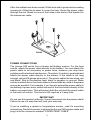
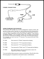
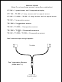
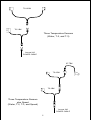
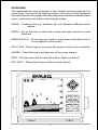
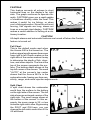
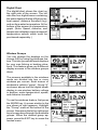
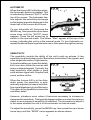
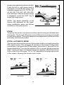
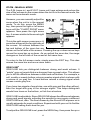
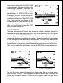
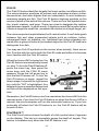
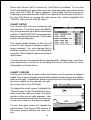
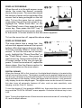
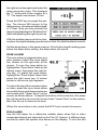
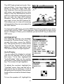
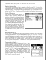
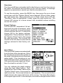
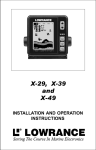
Accura 240
™
INST
ALLA
TION AND OPERA
TION
INSTALLA
ALLATION
OPERATION
INSTR
UCTIONS
INSTRUCTIONS
TABLE OF CONTENTS
INTRODUCTION .............................................................................................................................. 1
INSTALLATION - BRACKET ........................................................................................................... 1
POWER CONNECTIONS ................................................................................................................ 2
SPEED/TEMPERATURE SENSORS .............................................................................................. 3
KEYBOARD BASICS ....................................................................................................................... 6
OPERATION .................................................................................................................................... 7
POWER/LIGHTS .............................................................................................................................. 7
MENUS ............................................................................................................................................ 7
MODES ............................................................................................................................................ 7
AUTOMATIC ................................................................................................................................... 10
SENSITIVITY .................................................................................................................................. 10
RANGE ........................................................................................................................................... 11
ZOOM ............................................................................................................................................. 12
Automatic Operation ................................................................................................................... 12
Manual Operation ....................................................................................................................... 13
GRAYLINE® ................................................................................................................................... 13
CHART SPEED .............................................................................................................................. 14
FISH ID ........................................................................................................................................... 15
FISHTRACK™ ................................................................................................................................ 15
CHART SETUP ............................................................................................................................... 16
CHART CURSOR ....................................................................................................................... 16
DISPLAY ZOOM BAR ................................................................................................................ 17
DISPLAY ZONE BAR ................................................................................................................. 17
DIGITAL SONAR ........................................................................................................................ 17
ALARMS ......................................................................................................................................... 18
DEPTH ALARMS ........................................................................................................................ 18
ZONE ALARM ............................................................................................................................ 19
FISH ALARM .............................................................................................................................. 19
ADJUST CHART SURFACE CLARITY .......................................................................................... 20
ADVANCED SIGNAL PROCESSING (ASP) .................................................................................. 20
SYSTEM SETUP ............................................................................................................................ 21
AUDIO/DISPLAY ........................................................................................................................ 21
SYSTEM INFORMATION ........................................................................................................... 22
UNITS OF MEASURE ................................................................................................................ 22
RESET DISTANCE LOG ............................................................................................................ 22
TEMPERATURE GRAPH ........................................................................................................... 22
SIMULATOR ............................................................................................................................... 23
PRESET OPTIONS .................................................................................................................... 23
KEEL OFFSET ........................................................................................................................... 23
CALIBRATE SPEED .................................................................................................................. 24
WINDOWS SUMMARY ................................................................................................................... 25
TROUBLESHOOTING .................................................................................................................... 26
WARRANTY ................................................................................................................................... 29
INTERNATIONAL SERVICE INFORMATION .................................................... INSIDE BACK COVER
Copyright © 2000, Eagle Electronics
All rights reserved.
All features and specifications subject to change without notice.
All screens in this manual are simulated.
INTRODUCTION
The Accura 240 is the latest member of the Eagle family that combines a
high performance sonar with a wide, high definition screen. Using menu
features and “soft-key” operation, the Accura 240 is also easy to use. The
wide screen shows the underwater world with high resolution and detail.
The display and keyboard are also lighted for night operation. The Accura
240 has digital boat speed, surface water temperature, and distance
travelled (log) screens.
SPECIFICATIONS
Dimensions ................................................ 4.94"H x 6.10"W x 2.71"D
Transmitter Frequency .............................. 192 kHz
Transmitter Power ..................................... 600 watts (p-p, typical)
75 watts (RMS, typical)
Display ...................................................... Film Supertwist LCD
240 vertical x 240 horizontal
57,600 total pixels
NOTICE!
The storage temperature for your unit is from -4 degrees to +167
degrees Fahrenheit (-20 degrees to +75 degrees Celsius). Extended
storage in temperatures higher or lower than specified will damage the
liquid crystal display in your unit. This type of damage is not covered
by the warranty. For more information, contact the factory's Customer
Service Department or your local service center.
INSTALLATION
MOUNTING
Install the Accura 240 in any convenient location, provided there is
clearance behind the unit when it is tilted for the best viewing angle. Holes
in the bracket base allow wood screw or through-bolt mounting. You may
need to place a piece of plywood on the back of thin fiberglass panels to
secure the mounting hardware. Make certain there is enough room behind
the unit to attach the power and transducer cables.
The Accura 240's gimbal bracket will also accept the GBSA-1 swivel
bracket adapter that lets you rotate the unit a full 360°.
The smallest hole that allows one power or transducer connector to pass
through is 3/4". After the hole is drilled, push the transducer connector up
through the hole first, then drop the power cable down through it.
1
After the cables have been routed, fill the hole with a good marine sealing
compound. Offset the bracket to cover the hole. Route the power cable
through the slot. Break out one of the holes in the back of the bracket for
the transducer cable.
FRONT
POWER CONNECTIONS
The Accura 240 works from a twelve-volt battery system. For the best
results, attach the power cable directly to the battery. You can attach the
power cable to an accessory or power buss, however you may have
problems with electrical interference. Therefore, it’s safer to go ahead and
attach the power cable directly to the battery. If the cable is not long
enough, splice #18 gauge wire onto it. The power cable has two wires, red
and black. Red is the positive lead, black is negative or ground. Make
certain to attach the in-line fuse holder to the red lead as close to the power
source as possible. For example, if you have to extend the power cable to
the battery or power buss, attach one end of the fuse holder directly to the
battery or power buss. This will protect both the unit and the power cable
in the event of a short. The Accura 240 requires a 3-amp fuse.
IMPORTANT!
Do not use this product without a 3-amp fuse wired into the power cable!
Failure to use a 3-amp fuse will void your warranty.
If you’re installing a speed or temperature sensor, read it's mounting
instructions. Route the sensor’s cable to the Accura 240's power cable and
plug it into the connector marked “SPEED/TEMP CABLE”
2
To Accura 240
POWER CONNECTIONS
RED
WIRE
BLACK
WIRE
TO SPEED/TEMP
OR TEMP SENSORS
(Not included)
3 amp
FUSE
12 VOLT
BATTERY
SPEED/TEMPERATURE SENSORS
The Accura 240 accepts up to three temperature sensors which can
monitor surface water, live well, air, and virtually any other temperature.
You do need to be careful when purchasing the temperature sensors,
however. Each temperature sensor has its own "address". The sensors
are labeled "Water", "T-2" (or Temp-2), and "T-3" (or Temp-3). If you want
two (or more) temperature readings, you'll need to use the proper sensors.
For example, you can't use two T-3 sensors. The sensors that will fit the
Accura 240 are:
TS-1BK
One sensor for "Water" temperature display.
TS-2BK
One sensor for "T-2" temperature display.
TS-3BK
One sensor for "T-3" temperature display.
TS-12BK
Two sensors for "Water" and "T-2" temperature displays.
ST-TBK
One speed sensor and one temperature sensor for
"Speed" and "Water" displays.
You can combine these sensors in many combinations. See the list on the
following page for temperature and speed sensor combinations.
3
Sensor Chart
(Note: Do not use these sensors in any other combination.)
ST-TBK = 1 speed sensor and 1 temperature display
ST-T BK + TS-2BK = 2 temp sensors and one speed sensor
ST-TBK + TS-2BK + TS-3BK = 3 temp sensors and one speed sensor
TS-1BK = 1 temperature sensor
TS-12BK = 2 temperature sensors
or
TS-1BK + TS-2BK = 2 temperature sensors
TS-12BK + TS-3BK = 3 temperature sensors
or
TS-1BK + TS-2BK +TS-3BK = 3 temperature sensors
Here's some sample wiring diagrams:
TS-12 BK
Two Temperature Sensors
(Water and T-2)
Accura 240
POWER CABLE
4
TS-12 BK
TS-3 BK
Three Temperature Sensors
(Water, T-2, and T-3)
Accura 240
POWER CABLE
ST-TBK
TS-2 BK
TS-3 BK
Three Temperature Sensors
plus Speed
(Water, T-2, T-3, and Speed)
Accura 240
POWER CABLE
5
KEYBOARD
The keyboard has keys arranged in two vertical columns beneath the
arrow keys. The menu key near the bottom left corner of the keyboard
activates the first menu page. The other keys are used to activate the alarm
menu, make menu selections, and change modes.
MODE - Pressing this key switches the unit between different sonar
modes.
MENU - Press this key to show the menus and gain access to most
functions.
ARROW KEYS - These keys are used to make menu selections and to
move objects on the screen.
ZOUT, ZIN - These keys let you zoom the screen in and out to see detail.
ALARM - Press this key to activate any of the sonar alarms.
PWR - This key turns the Accura 240 and it's lights on and off.
ENT, EXIT - These keys let you enter or erase values.
Accura 240
6
ZOUT
ZIN
MODE
ALARM
MENU
EXIT
ENT
PWR
OPERATION
POWER/LIGHTS
To turn the Accura 240 on, simply
press the PWR key. A screen similar
to the one at right appears.
The PWR key also controls the lights.
Once the Accura 240 is turned on,
press the PWR key to turn the lights
on. Press the PWR key again to turn
the lights off.
To turn the Accura 240 off, press and
hold the PWR key while a "countdown" appears on the screen. The unit will
shut itself off when the countdown reaches zero. Release the PWR key.
MENUS
The Accura 240 uses menus extensively to guide you through the
functions and features of the unit. To use the menus, simply press the
MENU key. The options on the menus let you to customize the unit to your
particular needs and water conditions. Use the up and down arrow keys to
move to different menus. The left and right arrow keys select and adjust
menu items. If you ever get lost in a menu, simply press the EXIT key. This
clears the menus from the screen.
MODES
The Accura 240 has five modes:
Fastrak™, digital/chart, split-chart, full
chart, and window groups. To select a
different mode, simply press the MODE
key. A screen similar to the one at right
appears. Press the up or down arrow
key to select the desired mode, then
press EXIT key to erase the modes
menu. A summary of the modes starts
on the next page.
7
FASTRAK
This feature converts all echoes to short
horizontal lines on the display’s far right
side. The graph continues to operate normally. FASTRAK gives you a rapid update
of conditions directly under the boat. This
makes it useful for ice fishing, or when
you’re fishing at anchor. Since the unit is not
moving, fish signals are long, drawn out
lines on a normal chart display. FASTRAK
makes a useful addition to fishing at a stationary location.
CAUTION!
All depth alarms and automatic features are turned off when the Fastrak
feature is turned on!
Full Chart
This is the default mode used when
the Accura 240 is first turned on. The
bottom signal scrolls across the screen
from right to left. Depth scales on the
right side of the screen makes it easy
to determine the depth of fish, structure, and other objects. The line at the
top of the screen represents the surface. The bottom depth shows at the
top left corner of the screen. The word
"AUTO" at the screen's top center
shows that the Accura 240 is in the
automatic mode, freeing you from sensitivity, range, and noise rejection adjustments.
Split Chart
A split chart shows the underwater
world from the surface to the bottom
on the right side of the screen. The left
side shows an enlarged version of the
right side. The zoom range shows at
the bottom of the screen. In this example, the zoom range is 2X, or two
times the right side's view. By pressing
the ZOUT and ZIN keys, you can
change the left side's zoom from 2X to
4X and back.
8
Digital/Chart
The digital/chart shows the chart on
the right side of the screen. The left
side has four digital boxes containing
the water depth at the top of the screen,
boat speed, distance travelled (log),
and surface water temperature. At the
bottom of the screen is a temperature
graph. (Note: Speed, distance, and
temperature displays require a speed/
temperature sensor which must be
purchased separately.)
Window Groups
You can change the displays on the
Accura 240 by using the windows feature. This lets you use different displays
for your own fishing or boating situations. This feature gives you 8 different
display screens in the window groups
alone.
The screens available in the windows
mode are divided into two or more
windows per screen. Each screen of
windows is called a “group”. Group “A”
as shown above has the digital depth
display in one window, battery voltage
in another, water temperature, speed,
and distance travelled.
To use the windows feature, first press
the MODE key. A screen similar to the
one shown at right appears. Highlight
the "Group" menu at the bottom of the
screen. Now press the left or right arrow
keys to sequence through the available
groups. When the desired group appears, press the EXIT key to erase the
modes menu.
9
AUTOMATIC
When the Accura 240 is first turned on,
the Automatic feature is enabled. This
is indicated by the word “AUTO” at the
top of the screen. The Automatic feature adjusts the sensitivity and range
so the bottom signal is displayed in the
lower half of the screen at all times.
To turn Automatic off, first press the
MENU key, then press the up or down
arrow keys until the "AUTO" menu
appears. Press the left arrow key to
switch to the manual mode. The letters “Man” appear at the top of the
screen, indicating the unit is in the manual mode. To turn Automatic on,
repeat the above steps to get the auto menu, then press the right arrow key.
SENSITIVITY
The sensitivity controls the ability of the unit to pick up echoes. A low
sensitivity level excludes much of the bottom information, fish signals, and
other target information. High sensitivity levels enables you to see this detail,
but it can also clutter the screen with
many undesired signals. Typically, the
best sensitivity level shows a good
solid bottom signal with Grayline and
some surface clutter.
When the Accura 240 is in the Automatic mode, the sensitivity is automatically adjusted to keep a solid bottom signal displayed, plus a little more.
This gives it the capability to show fish
and other detail.
However, situations occur where it becomes necessary to increase or
decrease the sensitivity. This typically happens when you wish to see more
detail, so an increase in sensitivity is indicated. The procedure to adjust it
is the same whether the unit is in the automatic or manual mode.
To adjust the sensitivity, press the MENU key, then press the up or down
arrow keys until the "SENS" menu appears as shown above.
10
The sensitivity menu has left and right arrows, plus a horizontal bar graph.
The graph gives a visual indication of the sensitivity level. The number to
the right of the bar graph shows the percentage of sensitivity in use.
To increase the sensitivity level, press the right arrow key. As you press
the key, the menu’s bar graph will grow wider and the percentage will
increase in value. You can also see the difference on the chart record as
it scrolls. When the sensitivity is at the desired level, release the key.
To decrease the sensitivity level, press the left arrow key. The bar graph
and percentage will decrease. When the sensitivity is at the desired level,
release the key. When you reach either the maximum or minimum limit, a
tone sounds.
To erase the menu, press the EXIT key.
RANGE - Automatic
When turned on for the first time, the
Accura 240 automatically places the
bottom signal in the lower half of the
screen. This is called Auto Ranging
and is part of the automatic function.
Typically, the range cannot be changed
manually while the unit is in automatic,
as shown at right. However, depending upon the bottom depth and the
current range, you can change the
range to a different depth. In the example screen shown below, the bottom depth has descended to a point where you can change the range to
150 feet. To do this, simply press the right arrow key while the Auto Range
menu is displayed. When you're finished with this menu, press the EXIT
key to erase it.
RANGE - Manual
The Accura 240 gives you complete
control over the range when it’s in the
manual mode.
To change the range, first make certain the Accura 240 is in the manual
mode. Next, press the MENU key and
the up or down arrow keys until the
11
range menu appears as shown at right.
Press the left or right arrow keys to
decrease or increase the range. The
available ranges are 0-5, 10, 20, 30,
40, 60, 100, 150, 200, 300, 500, 800,
and 1000 feet. After the desired range
is displayed, press the EXIT key to
erase the range menu.
NOTE: The depth capability of the
Accura 240 depends on the transducer installation, water and bottom
conditions, and other factors.
ZOOM
“Zooming” the picture is a common method used to enlarge small detail and
fish signals. The Accura 240 gives you two different zoom sizes, plus a split
screen zoom option. The zoom operation and adjustment is different in the
automatic and manual modes.
ZOOM - AUTOMATIC MODE
The only way to zoom the screen in automatic mode is to simply press the
ZIN (zoom-in) key. This enlarges all echoes on the screen to twice their
normal size. If you press the ZIN key again, the screen is "zoomed" to four
times normal size. To return the screen to 2X or normal, simply press the
ZOUT (zoom-out) key until the desired zoom appears. When the Accura
240 is in the 2X or 4X zooms, "2X" or "4X" appears in the lower right corner
of the screen, showing the current zoom mode.
NO ZOOM
2X ZOOM
12
ZOOM - MANUAL MODE
The Z-IN (zoom-in) and Z-OUT (zoom-out) keys enlarge and reduce the
size of the echoes on the screen when the unit is in the manual mode, the
same as the automatic mode.
However, you can manually adjust the
zoom when the unit is in the manual
mode. To do this, press the MENU
key, then press the right or left arrow
keys until the "CHART ZOOM" menu
appears. Now press the right arrow
key. A screen similar to the one at right
appears.
This is the split-screen zoom menu. A
zoom bar shows at the far right side of
the screen. All echoes between the
top and bottom of the zoom bar are
shown on the left side of the screen. Pressing the up or down arrow keys
moves the zoom bar up or down. As you adjust the zoom bar, the range
changes on the left side of the screen at the same time.
To return to the full-screen mode, simply press the EXIT key. This also
erases the zoom bar and move zoom menu.
GRAYLINE®
GRAYLINE lets you distinguish between strong and weak echoes. It
“paints” gray on targets that are stronger than a preset value. This allows
you to tell the difference between a hard and soft bottom. For example, a
soft, muddy or weedy bottom returns a weaker signal which is shown with
a narrow or no gray line. A hard bottom returns a strong signal which
causes a wide gray line.
If you have two signals of equal size, one with gray and the other without,
then the target with gray is the stronger signal. This helps distinguish
weeds from trees on the bottom, or fish from structure.
GRAYLINE is adjustable. Since GRAYLINE shows the difference between
strong and weak signals, adjusting the sensitivity may require a different
GRAYLINE level, also. The level chosen by the Accura 240 at power on is
usually adequate for most conditions. Experiment with your unit to find the
GRAYLINE setting that’s best for you.
To adjust the GRAYLINE level, press the MENU key, then press the up or
13
down arrow keys until the GRAYLINE
menu appears. A screen similar to the
one at right appears. Press the left
arrow key to decrease the gray level or
the right arrow key to increase it. The
percentage of GRAYLINE in use
changes as the arrow keys are
pressed. The bar chart also gives a
graphical indication of the GRAYLINE
level. You can see the change on the
screen (both on the menu and on the
chart record) as you press the keys.
After you’ve finished, press the EXIT
key to erase the menu.
CHART SPEED
The rate echoes scroll across the screen is called the chart speed. It’s
adjustable by first pressing the menu key, then pressing the up or down
arrow keys until the "CHT SPD" (chart speed) menu appears as shown
below left. Increase the chart speed by pressing the right arrow key or
decrease it by pressing the left arrow key. The percentage of chart speed
in use changes as the arrow keys are pressed. The bar chart also gives a
graphical indication of the chart speed. You can see the change on the
screen (both on the menu and on the chart record) as you press the keys.
After you’ve made the adjustment, press the EXIT key to erase the menu.
CHART SPEED MENU
CHART STOP MENU
To stop the chart, press the menu key, then press the up or down arrow
keys until the "CHART" menu appears as shown above right. Press the left
arrow key to stop the chart. To start the chart again, press the right arrow
key.
14
FISH ID
The Fish ID feature identifies targets that meet certain conditions as fish.
The microcomputer analyses all echoes and eliminates surface clutter,
thermoclines, and other signals that are undesirable. In most instances,
remaining targets are fish. The Fish ID feature displays symbols on the
screen in place of the actual fish echoes. There are four fish symbol sizes:
tiny, small, medium, and large. These are used to designate the relative
size between targets. In other words, it displays a small fish symbol when
it thinks a target is a small fish, a medium fish symbol on a larger target, etc.
The microcomputer is sophisticated, but it can be fooled. It can't distinguish
between fish and other suspended objects such as trotlines, turtles,
submerged floats, air bubbles, etc. Individual tree limbs extending outwards from a group of limbs is the hardest object for the Fish ID feature to
distinguish from fish.
You may see Fish ID symbols on the screen when actually, there are no
fish. Practice with the unit in both the Fish ID mode and without to become
more familiar with the Fish ID feature.
When the Accura 240 is turned on, the
Fish ID feature is automatically turned
on, also. To turn the Fish ID feature off,
press the menu key, then press the
arrow keys until the FISH ID menu
appears. Press the left arrow key to
turn the fish ID feature off. To turn the
Fish ID feature on again, repeat the
above steps, but press the right arrow
key until the "ON" is highlighted. Any
targets the microcomputer determines
are fish will be displayed as fish symbols.
Remember, the Fish ID feature can’t be used when the Accura 240 is in the
manual mode. If you turn the Fish ID feature on when the Accura 240 is in
manual, the microcomputer will turn the automatic feature on. If you turn
automatic off when the Fish ID feature is on, the Fish ID feature will be
turned off also.
FISHTRACK™
The FishTrack feature shows the depth of a fish symbol when it appears
on the display. This lets you accurately gauge the depth of targets. This
feature is available only when the Fish ID feature is on.
15
When the Accura 240 is turned on, FishTrack is enabled. To turn the
FishTrack feature off, press the menu key, then press the up or down arrow
keys until the FISH ID menu appears. Now press the left arrow key.
Pressing it once switches the FishTrack feature off, but leaves Fish ID on.
To turn FishTrack on, press the right arrow key, which highlights the
"TRACK" label on the Fish ID menu.
CHART SETUP
The Accura 240 lets you customize the
chart screen. To do this, press the MENU
key, then press the up or down arrow keys
until the "CHART SETUP" menu appears.
Now press the right arrow key. The screen
shown at right appears.
The digital depth display at the top left
corner of the screen normally shows in
large numbers. You can change this to
smaller numbers or turn it off completely
using the "Show Digital" menu at the top of
this screen.
You can also turn the temperature, speedometer, distance log, zoom bar,
zone alarm bar,or cursor on or off using this menu. See below for more
information on these items.
CHART CURSOR
The Accura 240 has a chart cursor that allows you to pinpoint a target’s
depth. The cursor is simply a horizontal line that extends across the display
from left to right. A depth box at the end of the line on the right side shows
the line’s depth. In the example at right,
the cursor (line) is at 29.8 feet.
To display the chart cursor, highlight the
"Show Cursor" on the "Chart Setup" menu,
then press the right arrow key. A screen
similar to the one at right appears. Use
the up and down arrow keys to move the
cursor up or down to the desired depth.
To turn the chart cursor off, repeat the
above steps. The Accura 240 returns to
the sonar screen without the chart cursor.
16
DISPLAY ZOOM BAR
When the unit is in the split-screen zoom
mode, the zoom bar doesn’t normally
show on the screen. The zoom bar shows
the section of water on the right side of the
screen that is being enlarged on the left
side. To turn the zoom bar on continuously when the split-screen mode is on,
highlight the "Show Zoom Bar" on the
"Chart Setup" menu, then press the right
arrow key. Now press the EXIT key. If
you're not in the split-screen mode, change
to that mode. A screen similar to the one above appears.
To turn the zoom bar off, repeat the above steps.
DISPLAY ZONE BAR
The zone alarm has a range bar. Any
echoes that appear between the top and
bottom of this bar triggers the zone alarm.
This bar normally doesn't show on the
screen. To turn the zone bar on continuously, highlight the "Show Zone Bar" on
the "Chart Setup" menu, then press the
right arrow key. Now press the EXIT key.
A screen similar to the one at right appears. To turn the zone bar off, repeat the
above steps. See the Alarms section for
more information on the zone alarm.
DIGITAL SONAR
When the Accura 240 is first turned on, the digital depth display is located at the
top left corner of the screen. This display comes from a separate digital sonar built
into the unit. It displays only the bottom depth. If it loses the bottom, the last known
depth will flash on the display. When the digital finds the bottom, it will automatically display the bottom depth again. The digital sonar can be turned off, however
this also turns all automatic features off also, such as auto sensitivity, auto
ranging, and the Fish ID. feature.
To turn the digital off, first press the MENU key, then press the up or down arrow
keys until the "DIGITAL SONAR" menu appears. Press the left arrow key to turn
it off.
Note: Turning the digital sonar off also turns the automatic mode off, including Fish
ID, and the depth alarms.
17
ALARMS
The Accura 240 has three different types of sonar alarms. The first is the
Fish Alarm. It sounds when the Fish I.D. feature determines an echo or
group of echoes is a fish. Another alarm is the Zone Alarm which consists
of a bar. Any echo that appears inside this bar triggers this alarm. The last
alarm is called the Depth Alarm. Only the bottom signal will trigger this
alarm. This is useful as an anchor watch, a shallow water alert, or for
navigation.
To adjust an alarm, first press the
ALARM key. The screen shown at
right appears. Follow the instructions
below for setting each alarm.
DEPTH ALARMS
The depth alarms sound a tone when
the bottom signal goes shallower than
the shallow alarm’s setting or deeper
than the deep alarm’s setting. For
example, if you set the shallow alarm
to ten feet, the alarm will sound a tone
if the bottom signal is less than ten feet. It will continue to sound until the
bottom goes deeper than 10 feet. The deep alarm works just the opposite.
It sounds a warning tone if the bottom depth goes deeper than the alarm's
setting. Both depth alarms work only off the digital bottom depth signals.
No other targets will trip these alarms. If you turn the digital off, the depth
alarms will be inoperative. These alarms can be used at the same time or
individually.
To adjust the shallow alarm, highlight
the "Shallow Depth" label. To adjust
the deep alarm, highlight the "Deep
Depth" label. Both alarms adjust identically. We'll use the shallow alarm as
an example. Highlight the "Shallow
Depth" label, then press the right arrow key. The screen shown at right
appears.
Use the up or down arrow keys to
select the number, the right and left
keys to move from number to number in the depth. For example, to set the
shallow alarm depth to 10 feet, press the right arrow key once, then press
the up arrow key once. The changes the second "0" to a "1". Next, press
18
the right arrow key again and press the
down arrow key once. This changes
the "1" at the end of the number to a
"0". The depth now shows 10 feet.
Press the ENT key to accept this setting. The Accura 240 returns to the
alarms menu, showing a shallow depth
of 10 feet. Now you can activate the
alarm by highlighting the "Shallow Alm"
label and pressing the right arrow key.
With the shallow alarm set at ten feet,
anytime the digital display goes below ten feet, the shallow alarm sounds.
Set the deep alarm in the same manner. If the bottom depth reading goes
below the deep alarm setting, the deep alarm will sound.
ZONE ALARM
The zone alarm is triggered when any
echo passes inside the zone alarm
bar, shown on the right side of the
screen. To turn the zone alarm on,
highlight the "Zone Alarm" label on the
alarms menu, then press the right arrow key. To adjust the zone alarm,
highlight the "Zone Adjust" label, then
press the right arrow key. A screen
similar to the one at right appears.
To adjust the top of the zone bar higher
or lower, press the up or down arrow
keys while the up and down arrows are
surrounding the "Upper Zone" on the
screen as shown above. To adjust the bottom of the zone bar, first press
the right arrow key to move the arrows to the "Lower Zone" on the screen,
then use the up or down arrow keys.
When the zone alarm is set, press the EXIT key to erase the menus.
FISH ALARM
Use the fish alarm for a distinctive audible alarm when fish or other
suspended objects are detected by the Fish I.D. feature. A different tone
sounds for each fish symbol size shown on the display. To turn the fish
19
alarm on, press the ALARM key, then highlight the "Fish Alarm" label and
press the right arrow key. The unit will revert to the sonar display with the
fish alarm turned on. Repeat the above steps to turn the fish alarm off.
Note: If the unit is in the manual mode, turning the Fish Alarm on will also
turn the automatic mode and Fish ID on, also.
ADJUST CHART SURFACE CLARITY
The markings extending downward from the zero line on the chart are
called “surface clutter.” These markings are caused by wave action, boat
wakes, temperature inversion, and other natural causes.
The Surface Clarity Control (SCC) reduces or eliminates surface clutter signals from the display. SCC varies the
sensitivity of the receiver, decreasing
it near the surface and gradually increasing it as the depth increases.
The maximum depth that SCC will
affect is 75% of the selected depth
range. For example, on a 0-60 foot
range with maximum SCC, surface
clutter will be reduced down to 45 feet.
There are three levels of SCC available on the Accura 240: low, medium,
and high. When it’s turned on for the first time, the SCC level is low. To
change it, press the MENU key, then press the up or down arrow keys until
the "Surface Clarity" menu appears. Now use the left or right arrow keys
to change it. When you're finished, press the EXIT key to erase the SCC
menu.
ASP (Advanced Signal Processing)
The ASP feature is a noise rejection system built into the Accura 240 that
constantly evaluates the effects of boat speed, water conditions, and
interference. This automatic feature gives you the best display possible
under most conditions.
The ASP feature is an effective tool in combating noise. In sonar terms,
noise is any undesired signal. It is caused by electrical and mechanical
sources such as bilge pumps, engine ignition systems and wiring, air
bubbles passing over the face of the transducer, even vibration from the
engine. In all cases, noise can produce unwanted marks on the display.
20
The ASP feature has two levels - Normal and High. If you have high noise
levels, try using the “High” ASP setting. However, if you are having trouble
with noise, we suggest that you take
steps to find the interference source
and fix it, rather than continually using
the unit with the high ASP setting.
However, there are times when you
may want to turn the ASP feature off.
This allows you to view all incoming
echoes before they are processed by
the ASP feature.
To change the ASP level, press the MENU key then press the up or down
arrow keys until the "ASP" menu appears. Now use the left or right arrow
keys to change it. When you're finished, press the EXIT key to erase the
ASP menu.
SYSTEM SETUP
The following features are available
through the "System Setup" menu. To
access this menu, press the MENU
key, then press the up or down arrow
keys until the "System Setup" menu
appears. Press the right arrow key.
The screen shown at right appears.
Audio/Display
You can adjust the display's contrast
and turn the speaker off or on using
this menu. To do this, highlight the
"Audio/Display" label on the system
setup menu, then press the right arrow
key. The screen at right appears.
To adjust the contrast, highlight the
"Contrast" menu, then use the left or
right arrow key to change it. Look at
the pattern at the bottom of this screen
to adjust the contrast for the best sharpness.
To turn the speaker off, highlight the
21
"Speaker" label, then press the left arrow key to turn it off.
System Information
This screen shows some basic data about the Accura 240. To view this,
highlight the "System Info" label on the System Setup menu, then press the
right arrow key. The system info screen appears. To erase this screen,
press the EXIT key. The Accura 240 returns to the System Setup menu.
Units of Measure
The Accura 240 normally shows the
depth in feet, speed in statute miles
per hour, distance in statute miles, and
temperature in degrees Fahrenheit.
You can change any of these settings
using the units of measure menu. To
do this, highlight the "Units of Measure" label on the System Setup menu,
then press the right arrow key. The
screen at right appears. Highlight the
item you want to change, then press
the right or left arrow key to change it.
To erase this screen, press the EXIT
key.
Reset Distance Log
If you have a speed sensor attached to the Accura 240, the unit starts
counting the distance you've travelled each time you turn it on. You can
reset this distance to zero by turning the unit off and on again, however, it's
easier to highlight the "Reset Distance Log" label on the System Setup
menu, then press the right arrow key. This resets the log and keeps you
in the System Setup menu. To erase this menu, press the EXIT key.
Temperature Graph
Some of the Accura 240's screens have a temperature graph, as shown at right. Normally, the
temperature graph has a 2° range. On the screen
shown at right, the temperature graph has a range
from 71° to 73°. You can change this range to 4°
or 10° using the "Temp Graph" label on the
System Setup menu. Highlight that label, then
press the right arrow key until the desired temperature graph range is highlighted. Press the
EXIT key to erase the menu.
22
Simulator
The Accura 240 has a simulator built in that lets you use it as if you are on
the water. All features and functions of the unit are usable. A message
appears occasionally to remind you that the simulator is on.
To use the simulator, press the MENU key, then press the up or down
arrow keys until the "System Setup" menu appears. When it does, press
the right arrow key. Now press the up or down arrow keys until the
"Simulator" label is highlighted. Finally, press the right arrow key. The
Accura 240 returns to a sonar screen with simulated echoes scrolling
across the screen.
Preset Options
The Accura 240 "remembers" all settings such as units of measure, auto/
manual, sensitivity, even when power
is removed from the unit. To return the
Accura 240 to the factory settings,
highlight the "Preset Options" label on
the "System Setup" menu, then press
the right arrow key. The Accura 240
returns to the full chart screen with all
settings returned to their factory values.
Keel Offset
The Accura 240 measures water depth
from the face of the transducer. Since
the transducer is below the surface of
the water, this distance is not the exact
water depth. If the transducer is one
foot below the surface, and the Accura
240 reports the water depth as 30 feet,
then the depth is actually 31 feet.
You can calibrate the depth reading
using the keel offset feature. First,
highlight the "Keel Offset" label on the
"System Setup" menu, then press the
right arrow key. The screen shown at right appears. The current bottom
depth shows in the upper left corner of the screen. The keel offset shows
in the upper right corner. In this example, we need to change the keel offset
23
so that the Accura 240 will add one
foot to the depth, since the transducer
is one foot below the surface. Press
the right arrow key, then the up or
down arrow keys until 1.0 appears in
the "Adj Keel" box, as shown at right,
then press the ENT key. This immediately changes the digital depth display
at the top of the screen by one foot.
Press the EXIT key to erase this menu.
Note: Another way to use the keel
offset feature is if you want to know the
depth of the water below the lowest
part of the boat, instead of the surface.
To do this, measure the lowest part of
the boat below the transducer. In this
example, we'll use 3 feet. Now, using
the keel offset feature, adjust the offset for a negative 3 feet, as shown at
right.
Please note that adjusting the keel
offset only affects the digital depth
display and all features that use the
digital depth, such as the depth alarms
and FishTrack. This doesn't affect the
chart at all.
Calibrate Speed
You can calibrate the speed display.
To do this, highlight the "Calibrate
Speed" label on the "System Setup"
menu, then press the right arrow key.
A screen similar to the one at right
appears.
If the digital speed display is slower
than your actual speed, add a positive
percentage to make it read faster. If
the digital speed display is faster, use a negative percentage to make it
read slower. Use the arrow keys to change the speed, then press the ENT
key. Press the EXIT key to erase this menu.
24
WINDOWS SUMMARY
GROUP "A"
GROUP "B"
GROUP "C"
GROUP "D"
GROUP "E"
GROUP "F"
GROUP "G"
GROUP "H"
25
TROUBLESHOOTING
If your unit is not working, or if you need technical help, please use the
following troubleshooting section before contacting the factory customer
service department. It may save you the trouble of returning your unit.
Unit won’t turn on:
1. Check the power cable’s connection at the unit. Also check the wiring.
2. Make certain the power cable is wired properly. The red wire connects
to the positive battery terminal, black to negative or ground.
3. Check the fuse.
4. Measure the battery voltage at the unit’s power connector. It should be
at least 11 volts. If it isn’t, the wiring to the unit is defective, the battery
terminals or wiring on the terminals are corroded, or the battery needs
charging.
Unit freezes, locks up, or operates erratically:
1. Electrical noise from the boat’s motor, trolling motor, or an accessory
may be interfering with the sonar unit. Rerouting the power and
transducer cables away from other electrical wiring on the boat may
help. Route the sonar unit’s power cable directly to the battery instead
of through a fuse block or ignition switch
2. Inspect the transducer cable for breaks, cuts, or pinched wires.
3. Check both the transducer and power connectors. Make certain both
are securely plugged in to the unit.
Weak bottom echo, digital readings erratic, or no fish signals:
1. Make certain transducer is pointing straight down. Clean the face of the
transducer. Oil, dirt, and fuel can cause a film to form on the transducer,
reducing its effectiveness. If the transducer is mounted inside the hull,
be sure it is shooting through only one layer of fiberglass and that it is
securely bonded to the hull. Do NOT use RTV silicone rubber adhesive
or Marinetex
2. Electrical noise from the boat’s motor can interfere with the sonar. This
causes the sonar to automatically increase its Discrimination or noise
rejection feature. This can cause the unit to eliminate weaker signals
such as fish or even structure from the display.
26
3. The water may be deeper than the sonar’s ability to find the bottom. If
the sonar can’t find the bottom signal while it’s in the automatic mode,
the digital will flash continuously. It may change the range to limits far
greater than the water you are in. If this happens, place the unit in the
manual mode, then change the range to a realistic one, (for example,
0-100 feet) and increase the sensitivity. As you move into shallower
water, a bottom signal should appear.
4. Check the battery voltage. If the voltage drops, the unit’s transmitter
power also drops, reducing its ability to find the bottom or targets.
Bottom echo disappears at high speeds or erratic digital reading or
weak bottom echo while boat is moving
1. The transducer may be in turbulent water. It must be mounted in a
smooth flow of water in order for the sonar to work at all boat speeds.
Air bubbles in the water disrupt the sonar signals, interfering with its
ability to find the bottom or other targets. The technical term for this is
Cavitation.
2. Electrical noise from the boat’s motor can interfere with the sonar. This
causes the sonar to automatically increase its Discrimination or noise
rejection feature. This can cause the unit to eliminate weaker signals
such as fish or even structure from the display. Try using resistor spark
plugs or routing the sonar unit’s power and transducer cables away
from other electrical wiring on the boat.
No fish arches when the Fish ID feature is off:
1. Make certain transducer is pointing straight down. This is the most
common problem if a partial arch is displayed.
2. The sensitivity may not be high enough. In order for the unit to display
a fish arch, it has to be able to receive the fish’s echo from the time it
enters the cone until it leaves. If the sensitivity is not high enough, the
unit shows the fish only when it is in the center of the cone.
3. Use the Zoom feature. It is much easier to display fish arches when
zoomed in on a small range of water than a large one. For example, you
will have much better luck seeing fish arches with a 30 to 60 foot range
than a 0 to 60 foot range. This enlarges the targets, allowing the display
to show much more detail.
4. The boat must be moving at a slow trolling speed to see fish arches.
If the boat is motionless, fish stay in the cone, showing on the screen
as straight horizontal lines.
27
NOISE
A major cause of sonar problems is electrical noise. This usually appears
on the sonar’s display as random patterns of dots or lines. In severe cases,
it can completely cover the screen with black dots, or cause the unit
operate erratically, or not at all.
To eliminate or minimize the effects of electrical noise, first try to determine
the cause. With the boat at rest in the water, the first thing you should do
is turn all electrical equipment on the boat off. Make certain the engine is
off, also. Turn your Accura 240 on, then turn off ASP (Advanced Signal
Processing). There should be a steady bottom signal on the display. Now
turn on each piece of electrical equipment on the boat and view the effect
on the sonar’s display. For example, turn on the bilge pump and view the
sonar display for noise. If no noise is present, turn the pump off, then turn
on the VHF radio and transmit. Keep doing this until all electrical equipment
has been turned on, their effect on the sonar display noted, then turned off.
If you find noise interference from an electrical instrument, trolling motor,
pump, or radio, try to isolate the problem. You can usually reroute the sonar
unit’s power cable and transducer cable away from the wiring that is
causing the interference. VHF radio antenna cables radiate noise when
transmitting, so be certain to keep the sonar’s wires away from it. You may
need to route the sonar unit’s power cable directly to the battery to isolate
it from other wiring on the boat.
If no noise displays on the sonar unit from electrical equipment, then make
certain everything except the sonar unit is turned off, then start the engine.
Increase the RPM with the gearshift in neutral. If noise appears on the
display, the problem could be one of three things; spark plugs, alternator,
or tachometer wiring. Try using resistor spark plugs, alternator filters, or
routing the sonar unit’s power cable away from engine wiring. Again,
routing the power cable directly to the battery helps eliminate noise
problems. Make certain to use the in-line fuse supplied with the unit when
wiring the power cable to the battery.
When no noise appears on the sonar unit after all of the above tests, then
the noise source is probably cavitation. Many novices or persons with
limited experience make hasty sonar installations which function perfectly
in shallow water, or when the boat is at rest. In nearly all cases, the cause
of the malfunction will be the location and/or angle of the transducer. The
face of the transducer must be placed in a location that has a smooth flow
of water at all boat speeds. Read your transducer owner’s manual for the
best mounting position.
28
EAGLE ELECTRONICS
FULL ONE-YEAR WARRANTY
“We", “our”, or “us” refers to EAGLE ELECTRONICS, a division of LEI, the manufacturer of
this product. “You” or “your” refers to the first person who purchases this product as a
consumer item for personal, family, or household use.
We warrant this product against defects or malfunctions in materials and workmanship, and
against failure to conform to this product’s written specifications, all for one year (1) from the
date of original purchase by you. WE MAKE NO OTHER EXPRESS WARRANTY OR
REPRESENTATION OF ANY KIND WHATSOEVER CONCERNING THIS PRODUCT.
Your remedies under this warranty will be available so long as you can show in a reasonable
manner that any defect or malfunction in materials or workmanship, or any non-conformity
with the product’s written specifications, occurred within one year from the date of your
original purchase, which must be substantiated by a dated sales receipt or sales slip. Any
such defect, malfunction, or non-conformity which occurs within one year from your original
purchase date will either be repaired without charge or be replaced with a new product
identical or reasonably equivalent to this product, at our option, within a reasonable time after
our receipt of the product. If such defect, malfunction, or non-conformity remains after a
reasonable number of attempts to repair by us, you may elect to obtain without charge a
replacement of the product or a refund for the product. THIS REPAIR, REPLACEMENT, OR
REFUND (AS JUST DESCRIBED) IS THE EXCLUSIVE REMEDY AVAILABLE TO YOU
AGAINST US FOR ANY DEFECT, MALFUNCTION, OR NON-CONFORMITY CONCERNING THE PRODUCT OR FOR ANY LOSS OR DAMAGE RESULTING FROM ANY OTHER
CAUSE WHATSOEVER. WE WILL NOT UNDER ANY CIRCUMSTANCES BE LIABLE TO
ANYONE FOR ANY SPECIAL, CONSEQUENTIAL, INCIDENTAL, OR OTHER INDIRECT
DAMAGE OF ANY KIND.
Some states do not allow the exclusion or limitation of incidental or consequential damages,
so the above limitations or exclusions may not apply to you.
This warranty does NOT apply in the following circumstances: (1) when the product has
been serviced or repaired by anyone other than us, (2) when the product has been
connected, installed, combined, altered, adjusted, or handled in a manner other than
according to the instructions furnished with the product, (3) when any serial number has
been effaced, altered, or removed, or (4) when any defect, problem, loss, or damage has
resulted from any accident, misuse, negligence, or carelessness, or from any failure to
provide reasonable and necessary maintenance in accordance with the instructions of the
owner’s manual for the product.
We reserve the right to make changes or improvements in our products from time to time
without incurring the obligation to install such improvements or changes on equipment or
items previously manufactured.
This warranty gives you specific legal rights and you may also have other rights which may
vary from state to state.
REMINDER: You must retain the sales slip or sales receipt proving the date of your original
purchase in case warranty service is ever required.
29
Notes:
30
How to Obtain Service
(Canadian Customers Only)
We back your investment in quality products with quick, expert service and genuine Eagle
replacement parts. If you need service or repairs, contact the Eagle Factory Customer
Service Department at the toll-free number listed below. A technician may be able to solve
the problem and save you the inconvenience of returning your unit. You will be asked for your
unit's serial number.
800-324-1354
Canada Only. Monday through Friday 8:00 A.M. - 8:00 P.M. Central Time.
How to Obtain Service
(International Customers Only)
If you need service or repairs, contact the dealer in the country you purchased your unit.
WARRANTY REPAIR WILL BE HONORED ONLY IN THE COUNTRY
UNIT WAS PURCHASED.
Please follow the shipping instructions shown below on this page if you have to mail your
unit to the dealer. For proper testing, repair, and service, send a brief note with the product
describing the problem. Be sure to include your name, return shipping address, and a
daytime telephone number.
Shipping Information
When sending a product for repair, we recommend you do the following:
1. Always use the original shipping container and filler material the product was packed
in when shipping your product.
2 Always insure the parcel against damage or loss during shipment. Lowrance does not
assume responsibility for goods lost or damaged in transit.
3. For proper testing, repair, and service, send a brief note with the product describing the
problem. Be sure to include your name, return shipping address, and a daytime
telephone number.
Accessory Ordering Information
To order accessories such as power cables or transducers, please contact:
1. Your local marine dealer. Most quality dealers that handle marine electronic equipment
should be able to assist you with these items. Consult your local telephone directory for
listings.
2. Canadian customers only can write:
Lowrance/Eagle Canada, 919 Matheson Blvd., E. Mississauga, Ontario L4W2R7
or fax 905-629-3118
31
How to Obtain Service
(U.S.A. Only)
We back your investment in quality products with quick, expert service and
genuine Eagle® replacement parts. If you're in the United States and you
have questions, please contact the Factory Customer Service Department
using our toll-free number listed below. You must send the unit to the
factory for warranty service or repair. Please call the factory before sending
the unit. You will be asked for your unit's serial number (shown above). Use
the following toll-free number:
800-324-1354
Your unit is covered by a full one-year warranty. (See page 29 for complete
warranty details.) If your unit fails and the failure is not covered by the
original warranty, Eagle has a flat-rate repair policy that covers your unit
and accessories packed with the unit at the factory. There is a 180-day
warranty on all non-warranty repairs from the factory, which is similar to the
original warranty, but is for 180 days rather than one year. For further
details, please call us at the above number.
Eagle Electronics may find it necessary to change or end our shipping policies, regulations,
and special offers at any time. We reserve the right to do so without notice.
Accessory Ordering Information
To order accessories such as power cables or transducers, please contact:
1) Your local marine dealer. Most quality dealers that handle marine
electronic equipment should be able to assist you with these items.
Consult your local telephone directory for listings.
2) LEI Extras, Inc. P.O. Box 129 Catoosa, OK 74015-0129
or call
800-324-0045
(USA orders only.)
LITHO IN U.S.A.
988-0135-36
32