1
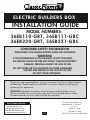
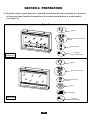
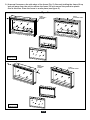
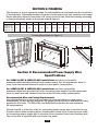
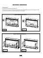
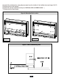
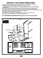
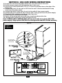
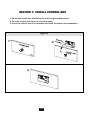
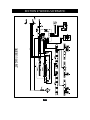
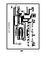
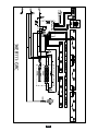
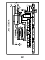
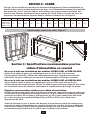
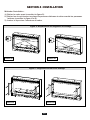
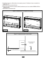
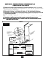
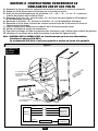
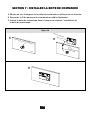
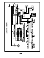
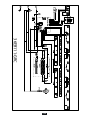
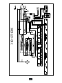
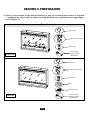
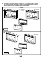
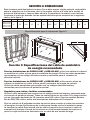
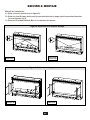
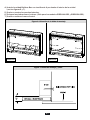
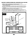
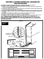
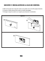
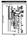
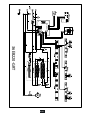
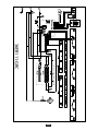
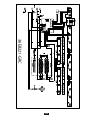
INSTRUCTION MANUAL ENCLOSED
MANUEL D’INSTRUCTION À L’INTÉRIEUR
MANUAL DE INSTRUCCIONES ADJUNTO
STOP
ATTENTION
STOP
IF YOU HAVE ANY PROBLEMS OR QUESTIONS, EMAIL
OR CALL CUSTOMER SERVICE BEFORE YOU RETURN
THIS PRODUCT TO THE STORE WHERE IT WAS PURCHASED.
For Customer Service: www.twinstarhome.com
in English Call: 866-661-1218
in Spanish Call: 866-661-1218
in French Call: 866-661-1218
PARE
ATENCIÓN
PARE
SI TIENE ALGÚN PROBLEMA O PREGUNTAS,
ENVÍE UN MENSAJE DE CORREO ELECTRÓNICO O LLAME AL SERVICIO
DE ATENCIÓN AL CLIENTE ANTES DE DEVOLVER
ESTE PRODUCTO A LA TIENDA EN LA QUE LO COMPRÓ.
Servicio de atención al cliente: www.twinstarhome.com
Línea para llamadas en inglés: 866-661-1218
Línea para llamadas en español: 866-661-1218
Línea para llamadas en francés: 866-661-1218
ARRÊT
ATTENTION
ARRÊT
SI VOUS AVEZ DES PROBLÈMES OU DES QUESTIONS,
ENVOYEZ UN COURRIEL AU SERVICE À LA CLIENTÈLE OU APPELEZ LE
SERVICE À LA CLIENTÈLE AVANT DE RETOURNER
CE PRODUIT OÙ VOUS L’AVEZ ACHETÉ.
Pour le service à la clientèle : www.twinstarhome.com
pour le service en anglais, appelez au: 866-661-1218
pour le service en espagnol, appelez au: 866-661-1218
pour le service en français, appelez au: 866-661-1218
INSTRUCTION MANUAL ENCLOSED
MANUEL D’INSTRUCTION À L’INTÉRIEUR
MANUAL DE INSTRUCCIONES ADJUNTO
ELECTRIC BUILDERS BOX
Electric Builder Box
INSTALLATION GUIDE
MODEL NUMBERS:
36EB110-GRT, 36EB111-GRC
36EB220-GRT, 36EB221-GRC
CONSUMER SAFETY INFORMATION
PLEASE READ THIS MANUAL BEFORE USING THIS APPLIANCE
WARNING
IF THE INFORMATION IN THIS MANUAL IS NOT FOLLOWED,
AN ELECTRIC SHOCK OR FIRE MAY RESULT CAUSING PROPERTY
DAMAGE, PERSONAL INJURY OR LOSS OF LIFE.
DO NOT STORE OR USE GASOLINE OR OTHER FLAMMABLE
VAPORS AND LIQUIDS IN THE VICINITY OF THIS
OR ANY OTHER APPLIANCE.
Thank you and congratulations on your purchase of a Classic Flame electric
builder box. Please read the installation instructions before installing and
operating this appliance.
IMPORTANT: Read all instructions and warnings carefully before using.
Failure to follow these instructions may result in a possible electric shock,
fire hazard and/ or injury and will void the warranty.
For Customer Service:
www.twinstarhome.com
In English Call: 866-661-1218
In French Call: 866-661-1218
In Spanish Call: 866-661-1218
E-1
Twin-Star International, Inc.
Delray Beach, FL 33445
U.S.A.
Made in China
Printed in China
©2012,Twin-Star International,Inc.
LISTINGS AND CODE APPROVALS
THE BUILDERS BOX SERIES HAS BEEN TESTED AND APPROVED IN ACCORDANCE WITH
CSA AND UL STANDARDS FOR FIXED AND LOCATION DEDICATED ELECTRIC ROOM HEATERS.
MODEL SPECIFICATIONS
VOLTAGE
MODEL NUMBER
DESCRIPTION
36EB110-GRT
36” TRADITIONAL
120
36EB220-GRT
36” TRADITIONAL
208/240
36EB111-GRC
36” CONTEMPORARY
120
36EB221-GRC
36” CONTEMPORARY
208/240
RATED POWER
WATTS
1440
2100/2800
1440
2100/2800
BTU
AMPS
4400
12
6700/8900 10.1/11.7
4400
12
6700/8900 10.1/11.7
WARNING
THE INSTALLATION OF THE BUILDER BOX MUST COMPLY WITH THE APPLICABLE
LOCAL AND / OR NATIONAL ELECTRICAL CODES AND UTILITY REQUIREMENTS.
THIS INSTALLATION SHOULD BE ENTRUSTED TO ONLY QUALIFIED
PERSONNNEL WHERE REQUIRED BY LAW.
INSTALLATION OVERVIEW
(Please read all instructions and user manual before installation)
Section 1.) Prepare product for installation.
Section 2.) Rough in framing following the recommended dimensions.
Section 3.) Recommended power supply wire specifications.
Section 4.) Mount the unit.
Section 5.) 120V wiring instructions.
Section 6.) 208/240V wiring instructions.
Section 7.) Install control box.
Section 8.) Check & test.
Section 9.) Electrical wiring diagram.
E-2
SECTION 1: PREPARATION
1.) Open the master carton, stone box , and wall mounted control box and make sure you have
all the parts listed. Remove the parts from the cartons and put them in a safe location
( see figure 1.)
Figure 1
3
Sign Wire
DOWN
UP
FLAME
TIMRER
Control Box with bracket
HEAT
SLEEP
FLAME
EMBERS
Remote Control
Power Cord
(Only for 36EB110-GRT)
36EB110-GRT
36EB220-GRT
Sign Wire
DOWN
UP
FLAME
TIMRER
DOWN
UP
LIGHT EFFECTS
Control Box with bracket
HEAT
SLEEP
FLAME
DOWN
LIGHTS
UP
LIGHTS
AUTO
Remote Control
Stones
Fireglass
36EB111-GRC
36EB221-GRC
Power Cord
(Only for 36EB111-GRC)
E-3
2.) Unscrew 2 screws on the side edge of the frame (Fig. 2). Securely holding the frame lift up
and pull away from the unit to remove the frame. Do not remove the protective plastic
film at this time. Place the frame in a safe place( see figure 2.)
Figure 2
3
STEP 1
UNSCREW 2
SCREWS
STEP 2
LIFT FRONT PANEL
36EB110-GRT
36EB220-GRT
STEP 1
UNSCREW 2
SCREWS
36EB111-GRC
36EB221-GRC
E-4
STEP 2
LIFT FRONT PANEL
SECTION
2: FRAMING
Section 1: Framing
This fireplace is a zero clearance design. No combustibles can be placed on the top surface
of the fireplace. Combustibles may be installed to the edge of the unit. Insulation and vapor
barrier should be placed a minimum of 2 inches from the unit. Build the framing according
to the specifications shown in the below table & figure 3.
MODEL
36EB110-GRT
36EB220-GRT
36EB111-GRC
36EB221-GRC
A
B
8”
35”
C
23.8”
D
24”
E
18”
F
G
H
36”
33.5”
34.7”
I
J
23.6”
7.8”
K
L
M
51”
36”
36”
Framing Specification: Figure 3
H
L
D
E
G
I
K
F
J
Section 3: Recommended Power Supply Wire
Specifications
For 36EB110-GRT & 36EB111-GRC installations use three non-metallic
sheathed cables with ground wire for the power supply. Use the appropriate wires to
meet local and national electrical codes for rated power consumption.
For 36EB220-GRT & 36EB221-GRC installations use four non-metallic
sheathed cables with ground wire for the incoming power supply. Use the appropriate
wires to meet local and national electrical codes for rated power consumption.
Recommended Wire and Fusing Requirements
Use appropriate wire to meet local and national electrical codes for rated power
consumption. All wire gauges should be 12 gauge solid wires with a dedicated 15 amp
breaker for 120 volts. For 208/240 volts Builders Box models use two dedicated
15 amp breakers.
Allow at least 8 in of service cable for connecting power supply wire to junction box on
fireplace insert when installing before finishing wall. Allow up to 4 feet of service cable
for connecting power supply wire to junction box on fireplace insert after finishing wall.
The control box is supplied with a six meter long cable.
E-5
M
SECTION 4: MOUNTING
Install Method:
1.) Remove front frame (see figure 2).
2.) Remove the screws holding side panels and then remove the side panels (see figure 4 & 5).
3.) Insert the builders box into the opening in the framing.
Figure 4: Mounting Tab Location
36EB111-GRC
36EB221-GRC
36EB110-GRT
36EB220-GRT
Figure 5: Wall and Mounting Tabs
36EB110-GRT
36EB220-GRT
36EB111-GRC
36EB221-GRC
E-6
4.) Install the builders box using 4pcs screws from the inside of the builder box (see figure 6 & 7).
5.) Remount the side panels.
6.) Place the stones as desired.(Only for 36EB111-GRC & 36EB221-GRC )
7.) Remount the front frame.
Figure 6: Mounting Tab Location
Place sto
nes here.
36EB110-GRT
36EB220-GRT
36EB111-GRC
36EB221-GRC
Figure 7: Wall and Mounting Tabs
E-7
SECTION 5: 120V WIRING INSTRUCTIONS
1.) Loosen the screw securing the junction box cover and remove the cover.
2.) Pull the power supply wires through the hole in the cover.
3.) Pull out the 4 wires marked L, N, G, S from the junction box on the side of the
builder box.
4.) Connect the black L wire from the unit to the black L from the power supply.
5.) Connect the white N wire from the unit to the white N from power supply.
6.) Connect the green ground G wire from the unit to the ground from the power supply.
7.) Plug the S wire connector into the provided sign wire.
8.) Ensure that all connections are tight.
9.) Secure all the wiring with wire-caps, then insert into the junction box.
10.) Remount the junction box cover (see figure 8 & 9.)
Note: 36EB110-GRT & 36EB111-GRC will only run on 120 volt operation.
Figure 8
120 V
Configration
Min. 14AWG WIRE FROM
POWER SUPPLY (NOT SUPPLIED)
Min. 14AWG WIRE
FROM POWER SUPPLY
(NOT SUPPLIED)
CONTROL
E-8
SECTION 6: 208/240V WIRING INSTRUCTIONS
1.) Loosen the screw securing the junction box cover and remove the cover.
2.) Pull the power supply wires through the hole in the cover.
3.) Pull out the 5 wires marked L1, L2, N, G, S from the junction box on the side of the
builder box.
4.) Connect the black L1 wire and red L2 from the unit to the two dedicated 15 amp
lines from the power supply.
5.) Connect the white N wire from the unit to the white N from power supply.
6.) Connect the green ground G wire from the unit to the ground from the power supply.
7.) Plug the S wire connector into the provided sign wire.
8.) Ensure that all connections are tight.
9.) Secure all the wiring with wire-caps, then insert into the junction box.
10.) Remount the junction box cover (see figure 8 & 9.)
Note: 36EB220-GRT & 36EB221-GRC will only work with a two phase 208/240v
power supply. Single phase 208/240v is not supported and will void the warranty.
Figure 9
208/240 V
Configration
White W/Red
Min. 14AWG WIRE
FROM POWER SUPPLY
(NOT SUPPLIED)
Min. 14AWG WIRE
FROM POWER SUPPLY
(NOT SUPPLIED)
L2 White W/Red Stripe
L2 White W/Red Stripe
CONTROL
E-9
SECTION 7: INSTALL CONTROL BOX
1. Mount the control box bracket to the wall using provided screws.
2. Connect control panel wire to extension cable.
3. Insert the control box to the bracket and finish the control box installation.
Figure 10
1
2
3
E-10
SECTION 8: CHECK & TEST
1.) Recheck that all the wiring works. Check that all connections are tight and correct to the
manual.
2.) Switch on the power supply to the unit.
3.) Press the POWER button on the control box.
4.) Using the wall controls test all the functions to ensure they are working correctly.
If any functions do not work recheck the wiring using sections 4 and 5 of this guide.
5.) Use the remote control to operate the unit, check all the functions.
6.)Finish wall construction work.
Caution: When the wiring is complete a thorough
“testing cycle” must be performed to check the
operation of the unit PRIOR to the wall / area being
closed up, tiled, and/or bricked.
E-11
SECTION 9: WIRING SCHEMATIC
36EB110-GRT
E-12
36EB220-GRT
E-13
36EB111-GRC
E-14
36EB221-GRC
E-15
FOYER ÉLECTRIQUE
Electric Builder Box
GUIDE D’INSTALLATION
NUMÉROS DE MODÈLES:
36EB110-GRT, 36EB111-GRC
36EB220-GRT, 36EB221-GRC
CONSIGNES DE SÉCURITÉ À L’USAGE DU CONSOMMATEUR
VEUILLEZ LIRE LE PRÉSENT MANUEL AVANT DE METTRE EN MARCHE CET APPAREIL
AVERTISSEMENT
SI LES CONSIGNES DU PRÉSENT MANUEL NE SONT PAS RESPECTÉES, LES RISQUES DE
CHOC ÉLECTRIQUE OU D’INCENDIE AUGMENTENT, CE QUI PEUT CAUSER DOMMAGES
MATÉRIELS, DES BLESSURES CORPORELLES OU MÊME LA MORT.
NE PAS ENTREPOSER OU UTILISER DE L’ESSENCE, DES SUBSTANCES VAPORISÉES
OU D’AUTRES LIQUIDES INFLAMMABLES À PROXIMITÉ DE CET APPAREIL OU DE
TOUT AUTRE APPAREIL.
Merci et félicitations d’avoir acheté un foyer Classic Flame. Veuillez lire les
instructions d’installation avant d’installer et de mettre en marche cet appareil.
IMPORTANT : Veuillez lire attentivement toutes les instructions et tous les
avertissements avant l’utilisation. Le non-respect de ces instructions risquerait de
causer des chocs électriques, des incendies ou des blessures corporelles et
annulerait la garantie.
Service à la clientèle :
www.twinstarhome.com
Service en anglais : 866-661-1218
Service en français : 866-661-1218
Service en espagnol : 866-661-1218
F-1
Twin-Star International, Inc.
Delray Beach, FL33445
États-Unis
Imprimé en Chine
Fabriqué en Chine
©2012, Twin-Star International,Inc.
HOMOLOGATIONS ET CODES
LA SÉRIE BUILDERS BOX A ÉTÉ TESTÉE ET APPROUVÉE CONFORMÉMENT AUX NORMES DE
L'ASSOCIATION CANADIENNE DE NORMALISATION (CSA) ET D'UNDERWRITERS LABORATORIES
INC. (U.L.) POUR LES RADIATEURS ÉLECTRIQUES FIXES ET ADAPTÉS À L’EMPLACEMENT.
CARACTÉRISTIQUES DU MODÈLE
NUMÉRO DU
MODÈLE
DESCRIPTION
36EB110-GRT
TRADITIONNEL, (36 po)
120
36EB220-GRT
TRADITIONNEL, (36 po)
208/240
36EB111-GRC
3CONTEMPORAIN, (36 po)
120
36EB221-GRC
3CONTEMPORAIN, (36 po)
208/240
TENSION
WATTS DE
PUISSANCE
NOMINALE
BTU
AMPÈRES
1440
4400
12
2100/2800
1440
2100/2800
6700/8900 10.1/11.7
4400
12
6700/8900 10.1/11.7
AVERTISSEMENT
L’INSTALLATION DE CE FOYER DOIT ÊTRE CONFORME AUX CODES DE L’ÉLECTRICITÉ
LOCAUX ET NATIONAUX AINSI QU’AUX EXIGENCES DES SERVICES PUBLICS APPLICABLES
CETTE INSTALLATION DEVRAIT ÊTRE CONFIÉE À UNE PERSONNE DÛMENT QUALIFIÉE,
LORSQUE LA LOI L’EXIGE.
APERÇU DE L’INSTALLATION
(Veuillez lire l’ensemble des instructions ainsi que le manuel d’utilisation avant de
procéder à l’installation)
Section 1. Préparer le produit en vue de l’installation.
Section 2. Tracer une ébauche du cadre du foyer en respectant les dimensions
recommandées.
Section 3. Spécifications relatives aux câbles d’alimentation en courant recommandés.
Section 4. Installer l’unité.
Section 5. Instruction sur le câblage de 120 V.
Section 6. Instruction sur le câblage de 208 et 240 V.
Section 7. Installer la boîte de commande.
Section 8. Vérification et mise à l’essai.
Section 9. Schéma du câblage électrique.
F-2
SECTION 1 : PRÉPARATION
1.) Ouvrir l’emballage d’expédition, la boîte de pierres et la boîte de commande murale, et
s’assurer que toutes les pièces indiquées sont présentes. Retirer les pièces de leurs boîtes et
les mettre en lieu sûr (consulter la figure 1.)
Figure 1
3
Fil d’interconnexion
DOWN
UP
FLAME
TIMRER
Boîte de commande
avec support
HEAT
SLEEP
FLAME
EMBERS
Télécommande
Cordon d’alimentation
(Seulement pour le modèle
36EB110-GRT)
36EB110-GRT
36EB220-GRT
Fil d’interconnexion
DOWN
UP
FLAME
TIMRER
DOWN
UP
LIGHT EFFECTS
Boîte de commande
avec support
HEAT
SLEEP
FLAME
DOWN
LIGHTS
UP
LIGHTS
AUTO
Télécommande
Pierres
Verre réfléchissant
36EB111-GRC
36EB221-GRC
Cordon d’alimentation
(Seulement pour le
modèle 36EB111-GRC)
F-3
2.) Dévisser deux vis sur le rebord latéral du cadre (figure 2). Pour retirer le cadre, le soulever
et l’éloigner de l’unité, tout en le tenant solidement. Ne pas retirer le film plastique
protecteur à cette étape de l’opération. Mettre le cadre dans un endroit sûr
(consulter la figure 2).
Figure 2
3
ÉTAPE 1 : DÉVISSER
DEUX VIS
ÉTAPE 2 : SOULEVER
LE PANNEAU AVANT
36EB110-GRT
36EB220-GRT
ÉTAPE 1 : DÉVISSER
DEUX VIS
36EB111-GRC
36EB221-GRC
F-4
ÉTAPE 2 : SOULEVER
LE PANNEAU AVANT
SECTION 2 : CADRE
Section
1: Framing
Ce foyer est un modèle non soumis
aux normes
de dégagement. Aucun combustible ne
peut être placé sur la surface supérieure du foyer. Les combustibles peuvent être installés
aux abords de l’unité. Les pare-vapeur et la barrière par contournement devraient être
placés à une distance minimale de deux pouces de l’unité. Monter le cadre du foyer en
respectant les spécifications figurant dans le tableau ci-dessous et à la figure 3.
MODÈLE
A
B
36EB110-GRT
36EB220-GRT
36EB111-GRC
36EB221-GRC
8”
35”
C
D
23.8”
24”
E
18”
F
G
H
36”
33.5”
34.7”
I
J
23.6”
7.8”
K
L
M
51”
36”
36”
Spécifications relatives au cadre : Figure 3
H
L
D
E
G
I
K
F
J
Section 3 : Spécifications recommandées pour les
câbles d’alimentation en courant
En ce qui a trait aux installations des modèles 36EB110-GRT et 36EB111-GRC,
utiliser trois câbles à gaine non métalliques avec un fil de mise à la terre pour
l’alimentation électrique. Utiliser les câbles appropriés pour répondre aux codes de
l’électricité locaux et nationaux concernant la consommation d’énergie nominale.
En ce qui a trait aux installations des modèles 36EB220-GRT et 36EB221-GRC,
utiliser quatre câbles à gaine non métalliques avec un fil de mise à la terre pour
l’alimentation électrique entrante. Utiliser les câbles appropriés pour répondre aux codes
de l’électricité locaux et nationaux concernant la consommation d’énergie nominale.
Exigences recommandées relatives aux câbles et aux fusibles
Utiliser les câbles appropriés pour répondre aux codes de l’électricité locaux et nationaux
concernant la consommation d’énergie nominale. Tous les câbles devraient être de type
massif et de calibre 12 et reliés à un disjoncteur de 15 A d’une capacité de 120 volts.
En ce qui concerne les modèles Builders Box de 208 ou 240 volts, utiliser deux
disjoncteurs de 15 A.
Avant de terminer le mur, s’assurer de disposer d’au moins huit pieds de câblage pour
raccorder le câble d’alimentation en courant à la boîte de jonction du foyer encastrable,
ce qui devrait laisser jusqu’à quatre pieds de câblage une fois le mur terminé. La boîte
de commande est fournie avec un câble d’une longueur de six mètres.
F-5
M
SECTION 4 : INSTALLATION
Méthode d’installation :
1.) Retirer le cadre avant (consulter la figure 2).
2.) Retirer les vis qui tiennent en place les panneaux latéraux et retirer ensuite les panneaux
latéraux (consulter la figure 4 et 5).
3) Insérer le foyer dans l’ouverture du cadre.
Figure 4 : Emplacement des languettes de montage
36EB111-GRC
36EB221-GRC
36EB110-GRT
36EB220-GRT
Figure 5 : Languettes murales et de montage
36EB110-GRT
36EB220-GRT
36EB111-GRC
36EB221-GRC
F-6
4.) Installer le foyer en utilisant des vis de quatre pouces à l’intérieur du foyer (consulter les
figures 6 et 7).
5.) Réinstaller les panneaux latéraux.
6.) Placer les pierres dans la position désirée (seulement pour les modèles 36EB111 GRC et
36EB221 GRC).
7.) Réinstaller le panneau avant.
Figure 6 : Emplacement des languettes de montage
Place sto
nes here.
36EB111-GRC
36EB221-GRC
36EB110-GRT
36EB220-GRT
Figure 7 : Languettes murales et de montage
GOUJON
VUE DU DESSUS DE
L’INSERTION
AVANT
GYPSE/SHEETROCK
F-7
SECTION 5 : INSTRUCTIONS CONCERNANT LE
CÂBLAGE DE 120 VOLTS
1.) Desserrer la vis qui retient le couvercle de la boîte de jonction et retirer le couvercle.
2.) Passer les fils d’alimentation électrique par le trou du couvercle.
3.) Sortir les quatre fils désignés par les symboles « L », « N », « G », « S » à partir de la boîte
de jonction sur le côté du foyer.
4.) Raccorder le fil noir « L » du foyer au fil noir « L » de l’alimentation électrique.
5.) Raccorder le fil blanc « N » du foyer au fil blanc « N » de l’alimentation électrique.
6.) Raccorder le fil de mise à la terre de couleur verte du foyer au fil de mise à la terre de
l’alimentation électrique.
7.) Fixer le capuchon de connexion du câble « S » au fil d’interconnexion fourni.
8.) Vérifier la solidité de toutes les connexions.
9.) Fixer tout le câblage à l’aide de capuchons de connexion, puis l’insérer dans la boîte
de jonction.
10.) Replacer le couvercle de la boîte de jonction (consulter les figures 8 et 9).
Nota : Les modèles 36EB110-GRT et 36EB111-GRC ne fonctionneront qu’avec
une source de 120 volts.
Figure 8
Configuration
de 120 V
NOIR
BLANC
FIL D’ALIMENTATION
ÉLECTRIQUE DE
CALIBRE MIN.14 (NON
COMPRIS)
LE
VERT
FIL D’INTERCONNEXION
NOIR (FOURNI)
CÂBLE NOIR
COUVERCLE DE LA
BOÎTE DE JONCTION
BOÎTE DE
C
ER E
V
U R
CO RIÈ
R
A
DE
COMMAN
FOYE
R
FIL D’ALIMENTATION
ÉLECTRIQUE DE
CALIBRE MIN. 14
(NON COMPRIS)
CÂBLE NOIR
FIL D’INTERCONNEXION
NOIR (FOURNI)
BOÎTE DE
FIL NOIR (L)
FIL NOIR (L)
FIL BLANC (N)
FIL BLANC (N)
FIL VERT (G)
FIL VERT (G)
JONCTION
FIL NOIR (S)
CÂBLE D’EXTENSION
F-8
FIL NOIR (S)
ALIMENTATION
ÉLECTRIQUE DE
120 VOLTS
PANNEAU DE
DISJONCTEUR
BOÎTE DE
COMMANDE
SECTION 6 : INSTRUCTIONS CONCERNANT LE
CÂBLAGE DE 208 ET 240 VOLTS
1.) Desserrer la vis qui retient le couvercle de la boîte de jonction et retirer le couvercle.
2.) Passer les fils d’alimentation électrique par le trou du couvercle.
3.) Sortir les cinq fils désignés par les symboles « L1 », « L2 », « N », « G » et « S » à partir de
la boîte de jonction sur le côté du foyer.
4.) Raccorder le fil noir « L1 » et le fil rouge « L2 » du foyer aux deux lignes de 15 ampères
de l’alimentation électrique.
5.) Raccorder le fil blanc « N » du foyer au fil blanc « N » de l’alimentation électrique.
6.) Raccorder le fil de mise à la terre de couleur verte du foyer au fil de mise à la terre de
l’alimentation électrique.
7.) Fixer le capuchon de connexion du câble S au fil d’interconnexion fourni.
8.) Vérifier la solidité de toutes les connexions.
9.) Fixer tout le câblage à l’aide de capuchons de connexion, puis l’insérer dans la boîte de jonction.
10.) Replacer le couvercle de la boîte de jonction (consulter les figures 8 et 9).
Nota : 36EB220-GRT & 36EB221-GRC ne fonctionneront qu’avec une alimentation
électrique 2 phases 208/240v.
Le monophasé 208/240v n’est pas supporté et mettra un terme à la garantie.
Figure 9
Configuration
de 208 ou
240 volts
NOIR
lanche
Bandeugbe
ou ro
LE
BLANC
FIL D’ALIMENTATION
ÉLECTRIQUE DE
CALIBRE MIN.14 (NON
COMPRIS)
C
ER E
V
U R
CO RIÈ
AR
VERT
FIL D’INTERCONNEXION
NOIR (FOURNI)
CÂBLE NOIR
FOYE
R
COUVERCLE DE LA
BOÎTE DE JONCTION
BOÎTE DE
FIL D’ALIMENTATION
ÉLECTRIQUE DE
CALIBRE MIN.14 (NON
COMPRIS)
DE
COMMAN
CÂBLE NOIR
FIL D’INTERCONNEXION
NOIR (FOURNI)
Fil Noir (L1)
Fil Noir (L1)
Bande Blanche ou Rouge(L2)
BOÎTE DE
JONCTION
Bande Blanche ou Rouge(L2)
Fil Blanc (N)
Fil Blanc (N)
Fil Vert (G)
Fil Vert (G)
FIL NOIR (S)
CÂBLE D’EXTENSION
F-9
ALIMENTATION
ÉLECTRIQUE DE
208/240 VOLTS
PANNEAU DE
DISJONCTEUR
BOÎTE DE
COMMANDE
SECTION 7 : INSTALLER LA BOÎTE DE COMMANDE
1. Monter au mur le support de la boîte de commande en utilisant les vis fournies.
2. Raccorder le fil du panneau de commande au câble d’extension.
3. Insérer la boîte de commande dans le support et terminer l’installation de
la boîte de commande.
Figure 10
BO
ÎTE
DE
CO
MM
AN
DE
CÂ
BLE
NO
2
IR
1
SUP
POR
T DE
BOÎT
E DE
COM
MAN
DE
CABL
E
D'INT
E
NOIR RCONNE
X
(FOU
RNI) ION
MUR
3
F-10
SECTION 8 : VÉRIFICATION ET MISE À L’ESSAI
1.) Vérifier de nouveau l’ensemble des connexions en s’assurant qu'elles sont solides
et conformes aux directives décrites dans le présent manuel.
2.) Mettre l’unité sous tension.
3.) Appuyer sur le bouton « POWER » de la boîte de commande.
4.) En utilisant les boutons de commande muraux, mettre à l’essai l’ensemble des
fonctionnalités afin de s’assurer que celles-ci permettent d’obtenir le résultat prévu.
Si l’une ou l’autre des fonctionnalités présente une défaillance, vérifier de nouveau les
connexions en consultant les sections 4 et 5 du présent manuel.
5.) Faire fonctionner l’unité à l’aide de la télécommande et vérifier l’ensemble des
fonctionnalités.
6.) Compléter la construction du mur.
Avertissement : Lorsque le câblage est terminé, un
« cycle d’essais » approfondis doit être mené pour vérifier
le fonctionnement du foyer, et ce, AVANT que le mur
soit refermé et recouvert de tuiles ou de briques.
F-11
SECTION 9: SCHÉMA DE CÂBLAGE
36EB110-GRT
F-12
36EB220-GRT
F-13
36EB111-GRC
F-14
36EB221-GRC
F-15
ELECTRIC BUILDERS BOX
Electric Builder Box
GUÍA DE INSTALACIÓN
NÚMEROS DE MODELOS:
36EB110-GRT, 36EB111-GRC
36EB220-GRT, 36EB221-GRC
INFORMACIÓN SOBRE SEGURIDAD PARA EL CONSUMIDOR
LEA ESTE MANUAL ANTES DE UTILIZAR EL APARATO
ADVERTENCIA
EN CASO DE NO SEGUIR LA INFORMACIÓN EN ESTE MANUAL, PODRÍA
OCURRIR UNA DESCARGA ELÉCTRICA O INCENDIO Y, COMO CONSECUENCIA,
DAÑOS A LA PROPIEDAD, LESIONES O LA PÉRDIDA DE LA VIDA.
NO GUARDE NI USE GASOLINA NI OTROS VAPORES Y LÍQUIDOS INFLAMABLES
EN LA CERCANÍA DE ESTE APARATO, NI DE CUALQUIER OTRO.
Gracias y felicitaciones por su adquisición de la unidad Electric Builders Box Classic
Flame. Lea las instrucciones de instalación antes de instalar y operar este aparato.
IMPORTANTE: Lea todas las instrucciones y advertencias con detenimiento antes
de utilizar este aparato.
Si no se siguen las instrucciones, podría provocarse riesgo de descarga eléctrica,
incendio o lesiones y, además, la garantía perdería validez.
Servicio de atención al cliente:
www.twinstarhome.com
Línea para llamadas en inglés: 866-661-1218
Línea para llamadas en francés: 866-661-1218
Línea para llamadas en español: 866-661-1218
S-1
Twin-Star International, Inc.
Delray Beach, FL33445
EE. UU.
Impreso en China
Fabricado en China
©2012,Twin-Star International,Inc.
APROBACIONES DE CÓDIGOS Y LISTAS
LA SERIE BUILDERS BOX SE HA PROBADO Y APROBADO DE ACUERDO CON LAS NORMAS
CSA y UL PARA LOS CALENTADORES DE INTERIOR ELÉCTRICOS FIJOS Y ESPECÍFICOS PARA
UNA UBICACIÓN.
ESPECIFICACIONES DEL MODELO
NÚMERO DE
MODELO
DESCRIPCIÓN
36EB110-GRT
TRADICIONAL DE 36”
120
36EB220-GRT
TRADICIONAL DE 36”
208/240
36EB111-GRC
CONTEMPORÁNEO DE 36”
120
36EB221-GRC
CONTEMPORÁNEO DE 36”
208/240
VOLTAJE
VATIOS DE
POTENCIA
NOMINAL
BTU
AMPERAJE
1440
4400
12
2100/2800
1440
2100/2800
6700/8900 10.1/11.7
4400
12
6700/8900 10.1/11.7
ADVERTENCIA
LA INSTALACIÓN DE LA UNIDAD BUILDERS BOX DEBE CUMPLIR CON LOS CÓDIGOS
ELÉCTRICOS Y LOS REQUISITOS DE SERVICIOS LOCALES O NACIONALES
CORRESPONDIENTES.
ESTA INSTALACIÓN DEBE ESTAR A CARGO DE PERSONAL DEBIDAMENTE CALIFICADO
SEGÚN LO EXIJA LA LEY.
DESCRIPCIÓN GENERAL DE LA INSTALACIÓN
(Lea todas las instrucciones y el manual del usuario antes de efectuar la instalación).
Sección 1: Preparación del producto para la instalación.
Sección 2: Enmarcado básico de acuerdo con las dimensiones recomendadas.
Sección 3: Especificaciones del cable de suministro de energía recomendado.
Sección 4: Montaje de la unidad.
Sección 5: Instrucciones del cableado de 120 voltios.
Sección 6: Instrucciones del cableado de 208/240 voltios.
Sección 7: Instalación de la caja de control.
Sección 8: Verificación y prueba.
Sección 9: Diagrama de las conexiones eléctricas.
S-2
SECCIÓN 1: PREPARACIÓN
1.) Abra la caja principal, la caja con las piedras y la caja con el control para montar en la pared,
y asegúrese de tener todas las piezas enumeradas. Retírelas y ubíquelas en un lugar seguro
(vea la figura 1).
Figure 3
Figura
1
Cable de señal
DOWN
UP
FLAME
TIMRER
Caja de control con soporte
HEAT
SLEEP
FLAME
EMBERS
Control remoto
Cable de energía
(Sólo para el modelo
36EB110-GRT
36EB220-GRT
36EB110-GRT)
Cable de señal
DOWN
UP
FLAME
TIMRER
DOWN
UP
LIGHT EFFECTS
Caja de control con soporte
HEAT
SLEEP
FLAME
DOWN
LIGHTS
UP
LIGHTS
AUTO
Control remoto
Piedras
Cristal del mueble
36EB111-GRC
36EB221-GRC
Cable de energía
(Sólo para el modelo
36EB111-GRC)
S-3
2.) Desenrosque dos tornillos del borde del marco (Fig. 2). Para quitar el marco, sujételo
con firmeza, levántelo y sáquelo de la unidad. No quite la película plástica protectora
todavía. Coloque el marco en un lugar seguro (vea la figura 2).
Figure 3
Figura
2
PASO 1: DESENROSQUE
2 TORNILLOS.
PASO 2: LEVANTE EL
PANEL FRONTAL
36EB110-GRT
36EB220-GRT
PASO 1: DESENROSQUE
2 TORNILLOS.
36EB111-GRC
36EB221-GRC
S-4
PASO 2: LEVANTE EL
PANEL FRONTAL
SECCIÓN
2: ENMARCADO
Section 1: Framing
Esta chimenea está diseñada sin holgura. No se debe apoyar ningún material combustible
sobre la superficie de la chimenea, pero sí se pueden colocar a la orilla de la unidad. La
barrera de aislamiento y vapor se debe ubicar a 2 pulgadas de la unidad, como mínimo.
Construya el marco de acuerdo con las especificaciones que se muestran en la siguiente
tabla y en la figura 3.
MODELO
A
B
36EB110-GRT
36EB220-GRT
36EB111-GRC
36EB221-GRC
8”
35”
C
23.8”
D
24”
E
18”
F
G
H
36”
33.5”
34.7”
I
J
23.6”
7.8”
K
L
M
51”
36”
36”
Especificaciones para el enmarcado: Figura 3
H
L
D
E
G
I
K
M
F
J
Sección 3: Especificaciones del cable de suministro
de energía recomendado
Para las instalaciones de 36EB110-GRT y 36EB111-GRC, utilice tres cables de cubierta
no metálica con cable a tierra para el suministro de energía. Utilice los cables apropiados
que cumplan con los códigos eléctricos locales y nacionales para el consumo de
potencia nominal.
Para las instalaciones de 36EB220-GRT y 36EB221-GRC, utilice cuatro cables de
cubierta no metálica con cable a tierra para el suministro de energía de entrada.
Utilice los cables apropiados que cumplan con los códigos eléctricos locales y
nacionales para el consumo de potencia nominal.
Requisitos para cables y fusibles recomendados
Utilice el cable apropiado que cumpla con los códigos eléctricos locales y nacionales para
el consumo de potencia nominal. Todos los cables deben ser de calibre 12 e hilos sencillos
con un interruptor dedicado de 15 amperios para 120 voltios. Para los modelos Builders
Box de 208/240 voltios, utilice dos interruptores dedicados de 15 amperios.
Deje un mínimo de 8 pulgadas de cable de servicio para conectar el cable de suministro
de energía a la caja de conexiones de la chimenea cuando realice la instalación antes
de terminar la pared. Deje hasta 4 pies de cable de servicio para conectar el cable de
suministro de energía a la caja de conexiones en la chimenea después de terminar la
pared. La caja de control se suministra con un cable de seis metros de largo.
S-5
SECCIÓN 4: MONTAJE
Método de instalación:
1.) Quite el marco frontal (vea la figura 2).
2.) Quite los tornillos que sostienen los paneles laterales y luego quite los paneles laterales
(vea las figuras 4 y 5).
3.) Coloque la unidad Builders Box en la abertura del marco.
Figura 4: Ubicación de la brida de montaje
36EB111-GRC
36EB221-GRC
36EB110-GRT
36EB220-GRT
Figura 5: Bridas de montaje y pared
36EB110-GRT
36EB220-GRT
36EB111-GRC
36EB221-GRC
S-6
4.) Instale la unidad Builders Box con tornillos de 4 pcs desde el interior de la unidad
(vea las figuras 6 y 7).
5.) Vuelva a montar los paneles laterales.
6.) Coloque las piedras como lo desee. (Sólo para los modelos 36EB111-GRC y 36EB221-GRC).
7.) Vuelva a montar el marco frontal.
Figura 6: Ubicación de la brida de montaje
Place sto
nes here.
36EB110-GRT
36EB220-GRT
36EB111-GRC
36EB221-GRC
Figura 7: Bridas de montaje y pared
S-7
SECCIÓN 5: INSTRUCCIONES DEL CABLEADO DE 120 VOLTIOS
1.) Afloje el tornillo que ajusta la tapa de la caja de conexiones y quítela.
2.) Pase los cables de alimentación por el orificio de la tapa.
3.) Saque los cuatro cables marcados con L, N, G y S de la caja de conexiones del lado
de la unidad Builders Box.
4.) Conecte el cable L negro de la unidad al cable L negro del suministro de energía.
5.) Conecte el cable N blanco de la unidad al cable N blanco del suministro de energía.
6.) Conecte el cable a tierra verde G de la unidad a la puesta a tierra del suministro
de energía.
7.) Enchufe el empalme de cables S en el cable de señal proporcionado.
8.) Asegúrese de que todas las conexiones estén ajustadas.
9.) Asegure todos los cables con tapones y luego insértelos en la caja de conexiones.
10.) Vuelva a colocar la tapa de la caja de conexiones (vea las figuras 8 y 9).
Nota: Los modelos 36EB110-GRT y 36EB111-GRC sólo funcionan con 120 voltios.
Figura 8
Configuración
de 120 voltios
NEGRO
BLANCO
CABLE DE Min.14 AWG
DEL SUMINISTRO DE
ENERGÍA (SE VENDE
POR SEPARADO)
NE
VERDE
JA
CA
CABLE DE SEÑAL
NEGRO (INCLUIDO)
CABLE NEGRO
TAPA DE CA
JA
CONEXIONES DE
O
EC
D
TAPA
TRAS
ER
A
CABLE DE Min.14 AWG
DEL SUMINISTRO DE
ENERGÍA (SE VENDE
POR SEPARADO)
ONTROL
CAJA DE C
CABLE NEGRO
CABLE DE SEÑAL
NEGRO (INCLUIDO)
CAJA DE
CONEXIONES
CABLE NEGRO L
CABLE NEGRO L
CABLE BLANCO N
CABLE BLANCO N
SUMINISTRO DE
ENERGÍA DE
120 VOLTIOS
CABLE VERDE G
CABLE VERDE G
PANEL DEL
INTERRUPTOR
CABLE NEGRO S
PROLONGADOR
S-8
CABLE NEGRO S
CAJA DE CONTROL
S
NE
XIO
SECCIÓN 6: INSTRUCCIONES DEL CABLEADO DE
208/240 VOLTIOS
1.) Afloje el tornillo que ajusta la tapa de la caja de conexiones y quítela.
2.) Pase los cables de alimentación por el orificio de la tapa.
3.) Saque los cinco cables marcados con L1, L2, N, G y S de la caja de conexiones del
lado de la unidad Builders Box.
4.) Conecte el cable L1 negro y el cable L2 rojo de la unidad a las dos líneas dedicadas
de 15 amperios del suministro de energía.
5.) Conecte el cable N blanco de la unidad al cable N blanco del suministro de energía.
6.) Conecte el cable a tierra verde G de la unidad a la puesta a tierra del suministro de
energía.
7.) Enchufe el empalme de cables S en el cable de señal proporcionado.
8.) Asegúrese de que todas las conexiones estén ajustadas.
9.) Asegure todos los cables con tapones y luego insértelos en la caja de conexiones.
10.) Vuelva a colocar la tapa de la caja de conexiones (vea las figuras 8 y 9).
Aviso: 36EB220-GRT & 36EB221-GRC solo funcionarán con una fase dos de
suministro de energía 208/240v. La fase simple 208/240v no es soportada y
anulará la garantía.
Figura 9
Configuración
de 208/240
voltios
NEGRO
con
Blancoja
tira ro
BLANCO
CABLE DE Min.14 AWG
DEL SUMINISTRO DE
ENERGÍA (SE VENDE
POR SEPARADO)
NE
VERDE
CABLE DE SEÑAL
NEGRO (INCLUIDO)
CABLE NEGRO
JA
CA
TAPA
TRAS
ER
A
TAPA DE CA
JA
CONEXIONE DE
S
CABLE DE Min.14 AWG
DEL SUMINISTRO DE
ENERGÍA (SE VENDE
POR SEPARADO)
DE
MMAN
ÎTE DE CO
BO
CABLE NEGRO
CABLE DE SEÑAL
NEGRO (INCLUIDO)
CAJA DE
CONEXIONES
CABLE NEGRO L1
CABLE NEGRO L1
Blanco con tira roja(L2)
Blanco con tira roja(L2)
CABLE BLANCO N
CABLE VERDE G
CABLE NEGRO S
CABLE BLANCO N
CABLE VERDE G
PROLONGADOR
CABLE NEGRO S
SUMINISTRO DE
ENERGÍA DE
120 VOLTIOS
PANEL DEL
INTERRUPTOR
CAJA DE CONTROL
D
O
EC
S
NE
XIO
SECCIÓN 7: INSTALACIÓN DE LA CAJA DE CONTROL
1. Monte el soporte de la caja de control en la pared con los tornillos proporcionados.
2. Conecte el cable del panel de control al cable prolongador.
3. Coloque la caja de control en el soporte para terminar la instalación.
Figura 10
CA
JA
CA
BL
1
SOPO
2
RTE
DE L
A CA
JA DE
EN
DE
EG
CO
RO
NT
RO
L
CON
TROL
CABLE
DE SEÑ
AL
NEGRO
(INCLUID
O)
PAR
ED
3
S-10
SECCIÓN 8: VERIFICACIÓN Y PRUEBA
1.) Vuelva a verificar que todo el cableado funcione correctamente, y asegúrese de que
todas las conexiones estén firmes y concuerden con el manual.
2.) Encienda el suministro de energía de la unidad.
3.) Presione el interruptor de encendido (POWER) en la caja de control.
4.) Use los controles de pared para probar todas las funciones, a fin de asegurarse de que
funcionan correctamente.
Si alguna función no funciona correctamente, vuelva a verificar el cableado; para ello,
siga las secciones 4 y 5 de esta guía.
5.) Utilice el control remoto para operar la unidad y verifique todas las funciones.
6.) Finalice el trabajo de construcción de la pared.
Precaución: Una vez que se haya finalizado el cableado,
se debe realizar un “ciclo de pruebas” completo para
verificar el funcionamiento de la unidad ANTES de tapar
el área o colocar ladrillos o azulejos en la pared.
S-11
SECCIÓN 9: ESQUEMA DE CONEXIONES
36EB110-GRT
S-12
36EB220-GRT
S-13
36EB111-GRC
E-14
36EB221-GRC
S-15
INSTRUCTION MANUAL ENCLOSED
MANUEL D’INSTRUCTION À L’INTÉRIEUR
MANUAL DE INSTRUCCIONES ADJUNTO
STOP
ATTENTION
STOP
IF YOU HAVE ANY PROBLEMS OR QUESTIONS, EMAIL
OR CALL CUSTOMER SERVICE BEFORE YOU RETURN
THIS PRODUCT TO THE STORE WHERE IT WAS PURCHASED.
For Customer Service: www.twinstarhome.com
in English Call: 866-661-1218
in Spanish Call: 866-661-1218
in French Call: 866-661-1218
PARE
ATENCIÓN
PARE
SI TIENE ALGÚN PROBLEMA O PREGUNTAS,
ENVÍE UN MENSAJE DE CORREO ELECTRÓNICO O LLAME AL SERVICIO
DE ATENCIÓN AL CLIENTE ANTES DE DEVOLVER
ESTE PRODUCTO A LA TIENDA EN LA QUE LO COMPRÓ.
Servicio de atención al cliente: www.twinstarhome.com
Línea para llamadas en inglés: 866-661-1218
Línea para llamadas en español: 866-661-1218
Línea para llamadas en francés: 866-661-1218
ARRÊT
ATTENTION
ARRÊT
SI VOUS AVEZ DES PROBLÈMES OU DES QUESTIONS,
ENVOYEZ UN COURRIEL AU SERVICE À LA CLIENTÈLE OU APPELEZ LE
SERVICE À LA CLIENTÈLE AVANT DE RETOURNER
CE PRODUIT OÙ VOUS L’AVEZ ACHETÉ.
Pour le service à la clientèle : www.twinstarhome.com
pour le service en anglais, appelez au: 866-661-1218
pour le service en espagnol, appelez au: 866-661-1218
pour le service en français, appelez au: 866-661-1218
INSTRUCTION MANUAL ENCLOSED
MANUEL D’INSTRUCTION À L’INTÉRIEUR
MANUAL DE INSTRUCCIONES ADJUNTO