1
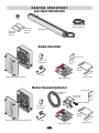
The Chamberlain Group, Inc.
845 Larch Avenue
Elmhurst, Illinois 60126-1196
www.liftmaster.com
MIRACL E - ONE ™
VEHICULAR ACTUATOR GATE OPERATOR
OWNER’S MANUAL
THE MIRACLE-ONE™ IS FOR USE ON VEHICULAR PASSAGE GATES ONLY
AND NOT INTENDED FOR USE ON PEDESTRIAN PASSAGE GATES.
TABLE OF CONTENTS
SPECIFICATIONS AND WARNINGS
WARNING
Carton Inventory and . . . . . . . . . . . . . . . . . . . . . . . . . . . . . . . . .
Specifications . . . . . . . . . . . . . . . . . . . . . . . . . . . . . . . . . . . . . . .
Model Classification . . . . . . . . . . . . . . . . . . . . . . . . . . . . . . . . . .
Safety Installation Information . . . . . . . . . . . . . . . . . . . . . . . . . .
Suggested Entrapment Protection Device Locations . . . . . . . . .
Safety Precautions . . . . . . . . . . . . . . . . . . . . . . . . . . . . . . . . . . .
Mechanical
WARNING
Electrical
2
3
4
5
6
7
INSTALLATION
CAUTION
Installation Setups . . . . . . . . . . . . . . . . . . . . . . . . . . . . . . . . . . . 8
Mounting Operator that Opens to the Outside . . . . . . . . . . . . . . 9
Mounting Operator that Opens to the Inside. . . . . . . . . . . . . . . 10
Mounting Operator . . . . . . . . . . . . . . . . . . . . . . . . . . . . . . . . . 1-13
Mounting Control Box. . . . . . . . . . . . . . . . . . . . . . . . . . . . . . . . 13
Mounting Operator(s) to Control Box . . . . . . . . . . . . . . . . . . . . 14
Control Board Descriptions. . . . . . . . . . . . . . . . . . . . . . . . . . . . 15
Surge Suppressor Connections . . . . . . . . . . . . . . . . . . . . . . 16-17
When you see these Safety Symbols and Signal Words on the
following pages, they will alert you to the possibility of serious
injury or death if you do not comply with the warnings that
accompany them. The hazard may come from something
mechanical or from electric shock. Read the warnings carefully.
When you see this Signal Word on the following pages, it will alert
you to the possibility of damage to your gate and/or the gate
operator if you do not comply with the cautionary statements that
accompany it. Read them carefully.
WIRING
IMPORTANT NOTE
Earth Ground Rod Installation . . . . . . . . . . . . . . . . . . . . . . . . .
Wiring operator(s) to Control Board. . . . . . . . . . . . . . . . . . . . .
DC Power Connection. . . . . . . . . . . . . . . . . . . . . . . . . . . . . . . .
UL Alarm Connection . . . . . . . . . . . . . . . . . . . . . . . . . . . . . . . .
Burglar Alarm Connections (House Alarm and Proximity Switch) . . . .
Wiring Additional Inputs (Strike Input). . . . . . . . . . . . . . . . . . .
24 Vdc External Loop Detector Wiring . . . . . . . . . . . . . . . . . . .
Entrapment Protection Devices (Non-Contact Sensors) . . . . . .
Maglock or Solenoid Connection . . . . . . . . . . . . . . . . . . . . . . .
• BEFORE attempting to install, operate or maintain the operator,
you must read and fully understand this manual and follow all
safety instructions.
• DO NOT attempt repair or service of your residential gate
operator unless you are an Authorized Service Technician.
18
19
20
21
21
22
23
24
25
ADJUSTMENTS
Set Gate Opening Direction. . . . . . . . . . . . . . . . . . . . . . . . . . . .
Setting the Timer . . . . . . . . . . . . . . . . . . . . . . . . . . . . . . . . . . .
Limit Switch Adjustments. . . . . . . . . . . . . . . . . . . . . . . . . . . . .
Adjusting Reverse Sensor. . . . . . . . . . . . . . . . . . . . . . . . . . . . .
Positive Stop Setting . . . . . . . . . . . . . . . . . . . . . . . . . . . . . . . .
315 MHz Radio Receiver Programming . . . . . . . . . . . . . . . . . .
Close Delay for Overlapping Gates . . . . . . . . . . . . . . . . . . . . . .
26
26
27
28
28
29
30
MAINTENANCE AND OPERATION
Maintenance . . . . . . . . . . . . . . . . . . . . . . . . . . . . . . . . . . . . . . . 31
Built-In Reset Button . . . . . . . . . . . . . . . . . . . . . . . . . . . . . . . . 32
Audio Alarm . . . . . . . . . . . . . . . . . . . . . . . . . . . . . . . . . . . . . . . 32
TL
FAUET
RES
Emergency Manual Release . . . . . . . . . . . . . . . . . . 33
Troubleshooting . . . . . . . . . . . . . . . . . . . . . . . . . . . . . . . . . . 34-35
Wiring Schematics (Single and Master/Second) . . . . . . . . . 36-39
REPAIR PARTS
Repair Part Illustrations . . . . . . . . . . . . . . . . . . . . . . . . . . . . . . 40
Part Names and Numbers. . . . . . . . . . . . . . . . . . . . . . . . . . . . . 41
ACCESSORIES . . . . . . . . . . . . . . . . . . . . . . . . . . . . . . . . . . .
HOW TO ORDER REPAIR PARTS . . . . . . . . . . . . . . . . . .
WARRANTY POLICY . . . . . . . . . . . . . . . . . . . . . . . . . . . . . .
INSTALLATION CHECKLIST . . . . . . . . . . . . . . . . . . . . . . .
31
42
43
43
44
CARTON INVENTORY
Arm (Sold Individually)
2 Keys
Back Steel
Mounting
Bracket
Front Steel
Mounting
Bracket
Flexible Conduit with
Attachment Fitting
Operator Arm
Single Controller
Accessory Kit
34 Vdc 1.7 A
Transformer
Battery
Manual
UL Alarm
Control Box Assembly (Single)
Warranty Card
2 Warning Placards
Master/Second Controller
Accessory Kit
40 ft Shielded
Cable
Junction Box
with Cover
Terminal Connector
34 Vdc 1.7 A
Transformer
Bushing
Battery
Manual
Control Box Assembly (Master/Second)
UL Alarm
2 Warning Placards
2
Warranty Card
SPECIFICATIONS
Mechanical Specifications
Motor –
Cycles –
Shipping Weight:
Torque –
Finishing –
Capabilities –
Operator Travel Speed –
24 Vdc, 12 Amps.
100 / Day. (Consult factory for solar applications)
Single Unit: 58 lbs. – Master/Second: 89 lbs.
600 lbs. of torque.
Aluminum.
Maximum gate size 15' wide, 600 lbs.
14 to 18 seconds 90 opening.
Top
3.5"
39.5"
Front
Back
4"
5.75"
Side
Electrical Specifications
Running System –
Modular Board –
Sensor –
Top
5.25"
10.5"
12.25"
Uses a Microcontroller with built-in “watchdog” system.
Board uses LEDs to indicate all input and output functions.
When the gate makes contact with an object while opening or
closing, the gate will reverse for 1 second then go into neutral, so it
can be pushed by hand.
Timer –
Can be set from 3 to 60 seconds, or “push- open/stop/close”
operation.
Master/Second –
Dictates synchronized movement between two gate operators.
Safety Loop Input – Anti-tailgating system uses a “stop only” method of operation.
Will not work as a commercial loop system.
Alarm Output –
Can be interfaced with any home alarm system. Alarm will sound if
the gate is forced open manually.
Optional siren can be installed.
Stop/Reset Button – Stops gate or resets UL alarm.
Spike Suppressors – Protected by spike suppressors.
Alternate Outputs – Sensor alarm, alarm system, and magnetic locks.
Electronic Inputs –
Factory installed radio receiver, full-control system “pushopen/stop/close”, safety loop, photocell, telephone entry, and key
switch.
Housing Finish –
Weather proof.
Side
Front
Bottom
3
UL325 MODEL CLASSIFICATIONS
The Miracle-One™ is intended for use in Class I - III vehicular swing gate applications:
Class I – Residential vehicular gate operator
A vehicular gate operator (or system) intended for use in a home of one-to four single family dwellings,
or a garage or parking area associated therewith.
Class II – Commercial/General access vehicular gate operator
A vehicular gate operator (or system) intended for use in a commercial location or building such as a
multi-family housing unit (five or more single family units) hotel, garage, retail store or other building
servicing the general public.
Class III – industrial/limited access vehicular gate operator
A vehicular gate operator (or system) intended for use in a industrial location or building such as a
factory or loading dock area or other location not intended to service the general public.
UL325 ENTRAPMENT PROTECTION REQUIREMENTS
This chart illustrates the entrapment protection requirements for each of the three UL325 classes.
In order to complete a proper installation you must satisfy the
entrapment protection chart shown. That means that the installation
GATE OPERATOR ENTRAPMENT PROTECTION
must have one primary means of entrapment protection and one
Swing & Gate Barrier independent secondary means of entrapment protection. Both
UL325
Slide Gate Operator
(Arm) Operator
primary and secondary entrapment protection methods must be
Installation
Primary
Secondary
designed, arranged or configured to protect against entrapments in
Primary
Secondary
Classification
Type
Type
Type
Type
both the open and close directions of gate travel.
For Example: For a gate system that is installed on a single-family
Class I
A,
B1,
C,
B1,
B2
A
A or C
residence (UL325 Class I) you must provide the following: As your
Class II
or D
or D, B2
primary type of entrapment protection you must provide
A, B1, C
A, B1,
• Type A - inherent (built into the operator) entrapment sensing
Class III A, B1, B2
D or E
D or E
or C
or B2
and at least one of the following as your secondary
entrapment protection:
• Type B1 - Non-contact sensors such as photo-eyes,
• Type B2 - Contact sensors such as gate edges or
• Type D - Constant pressure control.
• Type E - Built-in audio alarm.
40-50399A
40-50399A
NOTE: UL requires that all installations must have warning signs placed in plain view on both sides of the gate to warn pedestrians of
the dangers of motorized gate systems.
64
SAFETY INSTALLATION INFORMATION
1. Vehicular gate systems provide convenience and security. Gate systems are comprised of many component parts. The gate
operator is only one component. Each gate system is specifically designed for an individual application.
2. Gate operating system designers, installers and users must take into account the possible hazards associated with each individual
application. Improperly designed, installed or maintained systems can create risks for the user as well as the bystander. Gate
systems design and installation must reduce public exposure to potential hazards.
3. A gate operator can create high levels of force in its function as a component part of a gate system. Therefore, safety features
must be incorporated into every design. Specific safety features include:
• Guards for Exposed Rollers
• Photoelectric Sensors
• Gate Edges
• Screen Mesh
• Vertical Posts
• Instructional and Precautionary Signage
4. Install the gate operator only when:
a. The operator is appropriate for the construction and the usage class of the gate.
b. All openings of a horizontal slide gate are guarded or screened from the bottom of the gate to a minimum of 4' (1.2 m) above
the ground to prevent a 2 1/4" (6 cm) diameter sphere from passing through the openings anywhere in the gate, and in that
portion of the adjacent fence that the gate covers in the open position.
c. All exposed pinch points are eliminated or guarded, and guarding is supplied for exposed rollers.
5. The operator is intended for installation only on gates used for vehicles. Pedestrians must be supplied with a separate access
opening. The pedestrian access opening shall be designed to promote pedestrian usage. Locate the gate such that persons will not
come in contact with the vehicular gate during the entire path of travel of the vehicular gate.
6. The gate must be installed in a location so that enough clearance is supplied between the gate and adjacent structures when
opening and closing to reduce the risk of entrapment. Swinging gates shall not open into public access areas.
7. The gate must be properly installed and work freely in both directions prior to the installation of the gate operator.
8. Controls intended for user activation must be located at least six feet (6') away from any moving part of the gate and where the
user is prevented from reaching over, under, around or through the gate to operate the controls. Outdoor or easily accessible
controls shall have a security feature to prevent unauthorized use.
9. The Stop and/or Reset (if provided separately) must be located in the line-of-sight of the gate. Activation of the reset control shall
not cause the operator to start.
10. A minimum of two (2) WARNING SIGNS shall be installed, one on each side of the gate where easily visible.
11. For a gate operator utilizing a non-contact sensor:
a. Reference owner’s manual regarding placement of non-contact sensor for each type of application.
b. Care shall be exercised to reduce the risk of nuisance tripping, such as when a vehicle trips the sensor while the gate is still
moving.
c. One or more non-contact sensors shall be located where the risk of entrapment or obstruction exists, such as the perimeter
reachable by a moving gate or barrier.
12. For a gate operator utilizing a contact sensor such as an edge sensor:
a. One or more contact sensors shall be located where the risk of entrapment or obstruction exists, such as at the leading edge,
trailing edge and post mounted both inside and outside of a vehicular horizontal slide gate.
b. One or more contact sensors shall be located at the bottom edge of a vehicular vertical lift gate.
c. A hard wired contact sensor shall be located and its wiring arranged so the communication between the sensor and the gate
operator is not subject to mechanical damage.
d. A wireless contact sensor such as the one that transmits radio frequency (RF) signals to the gate operator for entrapment
protection functions shall be located where the transmission of the signals are not obstructed or impeded by building structures,
natural landscaping or similar obstruction. A wireless contact sensor shall function under the intended end-use conditions.
e. One or more contact sensors shall be located on the inside and outside leading edge of a swing gate. Additionally, if the bottom
edge of a swing gate is greater than 6" (152 mm) above the ground at any point in its arc of travel, one or more contact sensors
shall be located on the bottom edge.
f. One or more contact sensors shall be located at the bottom edge of a vertical barrier (arm).
75
SUGGESTED ENTRAPMENT PROTECTION DEVICE LOCATIONS
WARNING
To prevent SERIOUS INJURY or DEATH from a moving gate:
• Entrapment protection devices MUST be installed to protect anyone who may come near a moving gate.
• Locate entrapment protection devices to protect in BOTH the open and close gate cycles.
• Locate entrapment protection devices to protect between moving gate and RIGID objects, such as posts or walls.
• A swinging gate shall NOT open into public access ways.
Non-Contact Sensors (Photo Electric Sensors)
Install photo electric sensors to protect
against any entrapment or safety conditions
encountered in your gate application.
See page 24.
ty
per
ro
ety
f
a
S
de Loop
i
s
In
Safety loops allows the gate to
stay open when vehicles are
obstructing the gate path.
Suggested for vehicles 14 feet or
longer. If a vehicle is shorter, a
center loop is recommended and
should be installed.
op
o
L
r
te
Cen
er
ty
e
f
a
S
D
g
an
ty
afe
S
e p
tsid Loo
u
O
e
tsid
rty
pe
Pro
Ou
A center loop protects during a
Close cycle of the gate. Safety
loops are required when using a
center loop.
See page 23.
y
ert
p
o
Pr
ety
f
e
a
d
tsi
e S op
d
i
Ou
s
o
Out L
E
n
tr
D ap
a m
n e
g n
e t
r
Ins
P
ide
ter p
n
e
C Loo
ety
f
a
S
de Loop
i
s
In
de
nsi
I
6
ty
P
er
rop
SAFETY PRECAUTIONS
The Miracle-One™ is for use on Vehicular Passage Gates ONLY
and NOT INTENDED for use on Pedestrian Passage Gates.
WARNING
To prevent SERIOUS INJURY or DEATH from a moving gate:
• Entrapment protection devices MUST be installed to protect
anyone who may come near a moving gate.
• Locate entrapment protection devices to protect in BOTH
the open and close gate cycles.
• Locate entrapment protection devices to protect between
moving gate and RIGID objects, such as posts.
• A swinging gate shall NOT open into public access ways.
DO NOT install next to
sprinklers or any area that
may expose bottom of
operator to water.
DO NOT install upside down.
DO NOT over-bend the
cord from the operator.
Doing this will cause the
wires to eventually break.
DO NOT install on a few pickets, they will bend.
Weld a reinforcement bar across entire gate.
DO NOT install on ANY pedestrian passageways or doorways.
DO NOT install on ANY pedestrian gates.
ty
per
o
r
P
ety
Safp
ide
s
t
e
Ou
sid oo
Out L
er
In
si
de
Pr
op
ety
Saf p
e
id o
Ins Lo
ty
ter
CenLoop
If the “Timer” is to be left in the “ON” position,
then add safety loops and a center loop.
DO NOT install on uphill or downhill gates.
97
Installation
INSTALLATION SETUPS
Single Operator
Maximum gate length 15 ft.
Maximum gate weight is 600 lbs.
Warning Placard on
both sides of gate.
Control Box
40-50399A
UL Alarm
Radio Receiver
Antenna
Water Tight Conduit
(Not provided)
Earth Ground Rod is highly recommended. See page 18.
NOTE: Weld a horizontal bar
across entire gate on any
installation for strength.
Master/Second Operators
Maximum gate length 15 ft. for each gate.
Maximum gate weight is 600 lbs. for each gate.
Master
Warning Placard on both sides of each gate.
40-50399A
40-50399A
Second
Junction
Box
Water Tight Conduit (Not provided)
Earth Ground Rod is highly recommended. See page 18.
8
Shielded low voltage wires.
MOUNTING OPERATOR THAT OPENS TO THE OUTSIDE
NOTE: Weld
Re-Bar Behind
Gate Hinges for
Maximum
Strength.
Gate Hinge
Gate Hinge
Heavy Steel Plate
for Reinforcement
(Not provided)
Steel Re-Bar
Heavy Steel Plate
for Reinforcement
(Not provided)
Back Steel Bracket
(Reinforce if
necessary)
Top
View
Back Steel Bracket
(Reinforce if
necessary)
Heavy Steel Plate
Gate Hinge
Gate Hinge
Typical Steel Post Setup
Indexing on
mounting hole
in the front
steel bracket.
6"
6"
Miracle-One™ in Open Position
Gate in Open Position
Typical Masonry Column Setup
Indexing on center hole in
the back steel bracket.
90° / 105°
Outside Property
Gate in Closed Position
Inside Property
7.75"
This Plate
Not Supplied
Miracle-One™
8.5"
25.75"
9
n
sitio
in Closed Po
MOUNTING OPERATOR THAT OPENS TO THE INSIDE
NOTE: Weld
Re-Bar Behind
Gate Hinges for
Maximum
Strength.
Gate Hinge
Gate Hinge
Steel Re-Bar
Heavy Steel Bracket
(Reinforce if necessary)
Heavy Steel Plates
for Reinforcement
(Not provided)
10" Minimum
Back Steel Plates
for Reinforcement
(Not provided)
Top
View
Back Steel Bracket
(Reinforce if
necessary)
Heavy Steel Plate
Gate Hinge
Gate Hinge
Typical Masonry Column Setup
8.5"
Typical Steel Post Setup
25.75"
Outside Property
Gate in Closed Position
Inside Property
6"
7.75"
Miracle-One™ in Closed Position
Miracle-One™
6"
Gate in Open Position
tion
in Open Posi
Indexing on center hole in
the back steel bracket.
Indexing on mounting hole in
the front steel bracket.
90° / 105°
10.25"
10
MOUNTING OPERATOR
Unscrew 4 screws on top of operator to remove cover.
Release the mechanical lock by turning the key to the horizontal
position.
If using a gate crossbar, weld bar across all pickets. Do not weld the crossbar on
just a few pickets, or they could bend.
The Miracle-One™ can be mounted on top of
the gate frame.
NOTE: See page 7 for mounting limitations.
Make sure that the operator is mounted level or it will not function properly. An off-level installation may cause the gate or operator to
fail prematurely.
11
MOUNTING OPERATOR (CONTINUED)
Bolt
NOTE: Front and back
bracket hardware must be
installed as shown. Nuts
must be tight or operator
will not work correctly.
Bushing
Traveler Carriage
Back Bracket
Washer on top of bracket.
Nut
Front Bracket
Nut
Position the Miracle-One™ horizontally level on the closed gate,
where desired. For strength purposes, the front steel bracket must be
attached in an area that can withstand heavy forces. Additional
reinforcement steel plates may be necessary for mounting.
2.25" vertical height between front and back brackets.
The gate must be in the closed position. Make sure the operator is
kept level while tack welding the front and back brackets and
reinforcement steel plates in position. After all tack welding is finished,
remove the operator to avoid damaging it!
With the operator removed, completely weld around the brackets and plates on the gate.
12
MOUNTING OPERATOR (CONTINUED)
After permanently mounting operator back on
brackets, lock the operator by turning the key to
the vertical position while pushing or pulling on
the gate until you hear the key release click into
place. The gate should not move after the
operator has been locked.
MOUNTING CONTROL BOX
Radio Receiver Board
Single Control Board
OR
Master/Second
Control Board
Battery
Rack
Surge Suppressor
Removable
Terminal
Control Box
Cover
Use the four mounting holes provided with four screws
and washers (recommend #10 thru 1/4-20 Bolts or
Screws) Do Not enlarge existing holes, drill new holes
or over tighten mounting screws.
Continued on next page.
Remove control box cover, control board, surge suppressor, radio
receiver board and battery rack from control box. The 3 radio
receiver wires can be unplugged from the surge suppressor using
the removable terminal connector.
13
CONNECTING OPERATOR(S) TO CONTROL BOX
NOTE: Reinstall all components back into control box when finished connecting operator(s) to control box. See previous page.
Single Operator
CAUTION
To AVOID damaging operator: DO NOT
over-bend the cord from the operator.
Doing this will cause the wires to
eventually break.
Flexible conduit’s attachment assembly.
Master/Second Operators
Master
Second
NOTE: All connections
need to be waterproof.
Flexible Conduit
(See Above)
Junction Box with Cover
Flexible Conduit
(See Above)
Bushing
Water Tight Conduit
(Not provided)
en
Gre
ld
Shie
en
Blue wn
Gre
Bro
Red
e
Blu
Bro
wn
Red
ite
k
Blac
Wh
Shielded Low Voltage Cable
14
ite
Wh ck
Bla
Terminal Connector
CONTROL BOARDS DESCRIPTIONS
Master/Second
Single
CAUTION
To AVOID damaging the control board, replace fuses ONLY
with same type and rating specified below.
1. Open or Close Relay LED
16. Charge OK LED
2. Control Relay LED
17. Power LED
3. Motor Fuse (8 Amp Single) (15 Amp Master/Second)
18. Timer Active LED
4. J1 Battery, Surge Suppressor and Reset Button Connection
19. Timer Adjustment (3 to 60 sec.) See page 26.
5. Strike Open LED
20. Switch - Timer, Off / On. See page 26.
6. Safety Loop LED
21. Close Delay Overlapping Gate, Off / On, Master/Second Only.
See page 30.
7. Radio Receiver LED
22. Stop by Positive Stop Option Switch, No / Yes. See page 28.
8. Center Loop LED
23. Switch - Open Inside / Open Outside. See page 26.
9. J3 Surge Suppressor Connection
24. Alarm Sensor LED
10. Central Control LED
25. Reverse Sensor Adjustment. See page 28.
11. Charging Power Fuse 1.5 Amp
26. Reverse Sensor LED
12. Board Fuse (2 Amp Single) (3 Amp Master/Second)
27. System On LED
13. Replace Charging Power Fuse LED
14. Replace Board Fuse LED
28. J4 Burglar Alarm & UL Audio Alarm Output Connector.
See page 21.
15. Batteries Low LED
29. J2 Maglock/Solenoid Connector. See page 25.
15
SURGE SUPPRESSOR CONNECTIONS
BLACK
WHITE
RED
3
4
5
6
7
8
9 10 11 12
13 14 15 16
Removable Terminal Connectors
1
7
2
3
10
5
Miracle-One™ Single
11
6
12
Ground
NOTE: You MUST use
Shielded Wire for the
blue and green lines.
Shield must be grounded.
1
Black
2
White
3
Red
4
Shielded
Brown
5
Blue
6
Green
Refer to Page 19
Miracle-One™ Second
Miracle-One™ Master
1
Black
2
White
NOTE: You MUST use Shielded Wire for the blue
and green lines. Shield must be grounded.
3
Red
4
Shielded
7
Brown
5
Blue
6
Green
Black
8
White
9
Red
10
Brown
11
Blue
12
Green
Shielded
Refer to Page 21
Proximity Switch
Normally Open
Part # APRS
N.O.
13
14
16
14
9
4
Refer to Page 19
13
8
Com
UL
SENSOR
GREEN
2
GREEN
BLUE
1
BLUE
BROWN
LIMITS
RED
BRAKE
WHITE
MOTOR
BURGLAR
ALARM
INPUT
SECOND ONLY
LIMITS
BLACK
BRAKE
BROWN
SINGLE OR MASTER ONLY
MOTOR
SURGE SUPPRESSOR CONNECTIONS
Green Ground Wire
Refer to Page 18
Refer to Page 20
Refer to Page 20
Solar Power
34 Vdc 1.7 A
Transformer
Polarity does not matter
Refer to Page 29
24 Vdc Factory Installed Radio Receiver Board
+24 Volt Red
Ground Black
Radio White
Refer to Page 22
Works as “3 Push Button” Control
N.O.
Remote NOT Included
Com
24 Vdc Photo Electric Sensors
Part # CPSN4
Refer to Page 24
Push Button
Key Switch
Card Reader
Digital Lock
Brown Wires
Blue Wires
N.O.
Works as “Open Only” Command
Com
+24V
Refer to Page 23
Gnd
N.O.
Com
24 Vdc Exit Loop
Part # A24
Card Reader
Digital Lock
TES
+24V
Refer to Page 22
Gnd
N.O.
Com
24 Vdc Safety Loop
Part # A24
+24V
Gnd
N.O.
Com
24 Vdc Center Loop
Part # A24
17
For technical support: 1-800-528-2806
Wiring
WARNING
To reduce the risk of SEVERE INJURY or DEATH:
• ANY maintenance to the operator or in the area near the
operator MUST NOT be performed until disconnecting the
electrical power and locking-out the power via the operator
power switch. Upon completion of maintenance the area
MUST be cleared and secured, at that time the unit may be
returned to service.
• Disconnect battery and 34 Vdc transformer or solar panel
BEFORE proceeding. Operator MUST be properly grounded
and connected in accordance with local electrical codes.
NOTE: The operator should be on a separate fused line of
adequate capacity.
• ALL electrical connections MUST be made by a qualified
individual.
• DO NOT install ANY wiring or attempt to run the operator
without consulting the wiring diagram. We recommend that
you install an optional reversing edge BEFORE proceeding
with the control station installation.
• ALL power wiring should be on a dedicated circuit and well
protected. The location of the power disconnect should be
visible and clearly labeled.
• ALL power and control wiring MUST be run in separate
conduit.
• BEFORE installing power wiring or control stations be sure
to follow ALL specifications and warnings described below.
Failure to do so may result in SEVERE INJURY to persons
and/or damage to operator.
All power wiring should be on a dedicated circuit and well protected.
NOTE: Calculated using NEC guidelines. Local codes and conditions must be reviewed for suitability of wire installation.
WARNING
CAUTION
To AVOID damaging 34 Vdc plug-in transformer, it MUST be
enclosed in a suitable weatherproof enclosure and provided
with proper weatherproof fixtures.
To prevent SERIOUS INJURY or DEATH from a moving gate:
DO NOT disconnect the audio alarm or reset button.
Use 14 gauge / 300 watt direct burial, landscape lighting wire NOT to exceed 500 ft., use 10 gauge wire up to 1000 ft. for transformer.
EARTH GROUND ROD INSTALLATION
Proper grounding gives an electrical charge, such as from an
electrical static discharge or a near lightning strike, a path from
which to dissipate its energy safely into the earth.
Surge Suppressor
MIRACLE SURGE PROTECTION
Without this path, the intense energy generated by lightning could
be directed towards the gate operator. Although nothing can
absorb the tremendous power of a direct lightning strike, proper
grounding can protect the gate operator in most cases.
®
LAKE FOREST, CALIFORNIA
www.eliteaccess.com
Within
3 Feet
REV A
12
13
14
15
16
17
18
19
20
21
22
23
24
25
+24 VAC
INPUT
LIMITS
+24 VOLT
11
RADIO
10
GROUND
9
STRIKE
INPUT
8
SAFETY
LOOP
7
CENTER
LOOP
BURGLAR
ALARM
INPUT
6
UL SENSOR
BRAKE
GREEN
LIMITS
SECOND ONLY
MOTOR
BLUE
5
BROWN
BLUE
4
RED
BROWN
3
WHITE
RED
2
BLACK
WHITE
1
GREEN
BRAKE
BLACK
SINGLE OR MASTER ONLY
MOTOR
26
27
The earth ground rod must be located within 3 feet from the gate
operator. Use the proper type earth ground rod for your local area.
Single piece of
12 gauge wire.
The ground wire must be a single, whole piece of wire. Never
splice two wires for the ground wire. If you should cut the ground
wire too short, break it, or destroy its integrity, replace it with a
single wire length.
Check local
codes for
proper
depth.
CAUTION
To AVOID damaging gas, power or other
underground utility lines, contact underground
utility locating companies BEFORE digging.
18
WIRING OPERATOR(S) TO CONTROL BOARD
Single Controller
WARNING
CAUTION
To prevent SERIOUS INJURY or DEATH
from a moving gate:
DO NOT connect the battery at this time.
To ENSURE proper operation of external devices:
• ENSURE bare wires make good contact inside
removable terminal connections.
• DO NOT let wire insulation interfere with connection.
Master/Second Controller
Water tight conduit not provided from the second operator.
21
19
DC POWER CONNECTION
NOTE: Master/second control board shown
to demonstrate proper conduit arrangement.
The same connection sequence applies to the
single control board.
Plug in the transformer and connect the
battery plug into the surge suppressor J1
battery plug. The “Timer” LED will flash
“3 times”.
After that, check the “Charge OK” LED......
......it must be “ON”.
If the board or charging LEDs are lit, replace
the fuses ONLY with type and sizes specified.
See page 35.
Earth Ground Rod
Highly Recommended!
See page 18
34 Vdc 1.7 A Plug-in Transformer
Battery Connection
Run power wires
in separate water
tight conduit.
(Not provided)
Master
Second
Input power to
transformer,
120 Vac, 60 Hz.
Polarity does NOT matter.
Use 14 gauge / 300 watt direct
burial, landscape lighting wire NOT
to exceed 500 ft. Use 10 gauge wire
up to 1000 ft. (Not provided)
CAUTION
To AVOID damaging 34 Vdc plug-in transformer, it MUST be
enclosed in a suitable weatherproof enclosure and provided
with proper weatherproof fixtures.
To AVOID damaging control board, DO NOT use the solar panel
and the plug-in transformer at the same time.
20
UL ALARM CONNECTION
This UL alarm is required for UL-325. It will go off after 2 consecutive events on the reverse sensor or UL sensor occur.
The UL alarm will sound for a period of 5 minutes unless the Stop/Reset button is pressed or a new command is received by the Strike
Input Connection. The reset button will shut off an activated audio alarm and reset the operator to function again. See page 32.
If the audio alarm goes off, always check the gate area for:
• Obstructions in the gate path.
• Damage to the gate and/or gate operator.
Connect the alarm plug
to the J4 “Alarm”
connection on the
control board. See
page 15.
Mount alarm on bottom of control box
to protect it from the weather.
BURGLAR ALARM CONNECTIONS
House Alarm
Connect the alarm plug
to the J4 “Alarm”
connection on the
control board.
See page 15.
The control board provides a relay with a normally open contact to
interface with a house alarm.
Control Board Relay
Contact Rating
0.5 Amp - 125 Vac
1 Amp - 24 Vdc
When interfacing with a house burglar alarm you must install
positive stops at the gate closed position. See page 28.
Proximity Switch
(Normally Open) If the gate is forced open without a valid
command, the proximity switch will be activated, causing
the house alarm to activate.
Surge Suppressor
Part # APRS
21
BLUE
GREEN
BURGLAR
ALARM
INPUT
9
10
11
12
13
14
15
CENTER
LOOP
BROWN
LIMITS
RED
BRAKE
UL SENSOR
Second ONLY
16
17
18
WIRING ADDITIONAL INPUTS
Strike Input #21 and #22
Wiring at #21 and #22 will be recognized as an Open Only command, and
Will Not close the gate.
To automatically Close the gate after an open cycle, the control board timer
must be turned ON. See page 26 about timer control.
Works as “Open Only” command.
Separate Power
for Device
Separate Power
for Device
Input #23 and #24
To provide a Close command use #23 and #24.
Wiring at #23 and #24 will be recognized as a Three Push Button command.
The First command will open the gate.
The Second command will stop the gate.
The Third command will close the gate.
Works as “3 Push Button” control.
Separate Power
for Device
22
24 VDC EXTERNAL LOOP DETECTOR WIRING
NOTE: Refer to the loop detector manual
for more specific information.
Part # A24 (Sold Individually)
24 Vdc “Center” Loop Detector - Allows gate to stay open when vehicles are obstructing
path. Caution: This option is for all vehicles including ones less than 14' long. Center loop
system requires two safety loops.
Center
24 Vdc “Safety” Loop Detector - Allows gate to stay open when vehicles are obstructing
path. Caution: Suggested for vehicles 14 feet or longer. If a vehicle is shorter, a center loop
system is recommended and should be installed.
If the “Inside” and “outside” safety loops are connected to the same loop detector:
• They should be series connected to the detector
Safety
• Have the same dimensions.
• Have the same number of wire turns. (See table below)
24 Vdc “Exit” Loop Detector - Allows gate to automatically open for exiting vehicles.
Installing Insulated Loop Wire
Exit
Number of Wire Turns Needed for Loop Sizes
Number of Wire Turns
Loop Perimeter
4
3
2
1
The wire is continuously wound in
the loop saw cut for the required
number of turns. One turn shown.
(Refer to table)
Saw Cut
The wire MUST be twisted together 6 twists per foot
from the end of the feeder slot to the loop detector.
Remove sharp inside corners
by making corner cuts
10 feet to 13 feet
14 feet to 26 feet
27 feet to 80 feet
80 feet and up
Home Run
Feeder Slot
1/8" to 1/4" Width Saw Cut
Contact your local dealer
for more information
about loop detectors.
Road Surface
Recommended Loop Wire XLPE 12-18 gauge
(Use heavier wire gauge for a more durable
loop area).
Sealant
Backer Rod
Insulated loop wire
3 turns shown, amount varies.
Refer to table
2" to 2.5" Depth
Saw Cut
23
NOTE: Wire mesh or reinforcement
imbedded in the road surface should be
cut away a minimum of 6 inches from
the perimeter of the loop.
ENTRAPMENT PROTECTION DEVICE
Non-Contact Sensors (24 Vdc Photo Electric Sensors)
To reduce the risk of injury, install photo electric sensors when the gate opens to less than 18” from a wall or any other object or
potential entrapment installation. If you are going to use a non-contact sensor as a secondary entrapment protection you should use a
recognized component to comply with the revised UL 325 intended to be used in class I or class II gate operator, like the following:
LiftMaster 24 Vdc Photo Electric Sensors. Follow the installation instructions provided with the photo electric sensors for accurate
placement of the sensors. Contact your local dealer for more information about photo electric sensors.
NOTE: Property owners are obligated to test photo sensors monthly.
Power
NOTE: If multiple pairs of
sensors are being used, all of
the sensor wires are to be
connected in parallel at the UL
Sensor Input on the Surge
Suppressor board.
Brown Wires
Blue Wires
Photo
Sensor
Potential Entrapment Area (Shaded)
Photo
Sensor
Top View of Wall
WARNING
To prevent SERIOUS INJURY or DEATH from a moving gate:
• Locate entrapment protection devices to protect in BOTH
the open and close gate cycles.
• Locate entrapment protection devices to protect between
moving gate and RIGID objects, such as posts or walls.
24
26
MAGLOCK OR SOLENOID CONNECTION
NOTE: ONLY the optional relay module will allow interface with the maglock or solenoid. The gate opening direction must be previously
set, see page 26.
Pin 1 is used when control board
is set to Open Inside.
Pin 3 is used when control board
is set to Open Outside.
The relay connection is the same on the master/second control board.
CAUTION
To ENSURE proper operation of external devices:
• ENSURE bare wires make good contact inside
removable terminal connector.
• DO NOT let wire insulation interfere with
connection.
Part # AMG1300
Maglock
Relay Contact Rating
0.5 Amp - 125 Vac
2 Amp - 30 Vdc
Part # 240MAU
N.C.
Common
Separate Power
for Maglock
Solenoid
N.O.
Common
Separate Power
for Solenoid
25
Adjustments
CAUTION
To reduce the risk of SERIOUS INJURY or DEATH:
Disconnect power BEFORE performing ANY adjustments.
SET GATE OPENING DIRECTION
Inside
Property
Gate Opens Outward
Gate Opens Inward
Inside Property
The opening direction works the same on
the single or master/second control board.
SETTING TIMER
The timer works the same on the single or master/second
control board.
To use the automatic close for the gate system, the
timer should be switched to the “ON” position.
Set Timer 3 to 60 seconds.
To use the push close command, the timer should
be switched to the “OFF” position.
NOTE: If a secondary safety sensor device is NOT used when
the timer is ON, the gate WILL hit a vehicle obstructing the
gate path during the close cycle.
26
LIMIT SWITCH ADJUSTMENTS
Remove operator cover and unlock the operator to adjust the gate’s traveling distance with
the limit switches. Loosen the 2 screws of each limit switch armature. Position the second
limit switches of each armature to stop the gate in the “full open” and “full closed” positions
(See illustration below). Re-tighten armature screws when gate positions are correct.
Replace operator cover with 4 screws when finished adjusting switches.
Second Limit Switch
First Limit Switch
Limit Switch Armature
First Limit Switch
Second Limit Switch
Limit Switch Armature
Second Limit Switch
Second Limit Switch
Gate in “full open” or “full closed” position.
27
ADJUSTING REVERSE SENSOR
Adjust the reverse sensor so when the gate hits any object while opening, it will STOP, and when the gate hits any object while closing,
it will REVERSE. The reverse sensor must be adjusted while the gate is opening or closing.
Sensor is too sensitive = if the gate stops in midcycle or reverses by itself.
Sensor is not sensitive enough = if the gate hits an object and does not stop or reverse.
Reverse sensor works the same on the single or
master/second control board.
Maximum Sensitivity
Minimum Sensitivity
POSITIVE STOP SETTING
This switch is to be turned to YES when a Physical Stop is used to stop the gate(s). This can allow the gate(s) to be locked or secured
in the closed position. The operator will use the “Positive Stop” at the gate’s closed position. It is still necessary to adjust the operator’s
limit switches at the closed position. The control board will look for the limit close first, then the positive stop.
Part # APSA
NOTE: Mount the positive stop on concrete
ONLY and secure with concrete anchors.
Positive stop works the same on the single or
master/second control board.
28
315 MHZ RADIO RECEIVER PROGRAMMING
Setting Output Duration (M) or (C):
The receiver is factory set at (M) Momentary. To verify, refer to the label next to jumper P2. (See illustration below)
For commercial applications, the receiver can be set to either (C) constant or (M) momentary closure.
With the jumper in the (M) momentary position, the contacts will close for 1/4 second regardless of the length of remote control
transmission.
With the jumper in (C) constant position, the contacts will stay closed as long as the remote control continues transmitting. Push and
HOLD remote button to open or close gate.
WARNING
CAUTION
To AVOID damaging receiver, disconnect
receiver’s power before changing jumper.
To reduce the risk of SERIOUS INJURY or DEATH, the use of
CONSTANT OPERATION on residential operators is
PROHIBITED.
Changing output duration from
Momentary to Constant.
P2
NOTE: Hand Held Remote
NOT Included.
Radio Receiver
Antenna
Radio Receiver
Antenna
Programming Radio Receiver:
1. Press and release the “Learn” button on the receiver. The learn indicator light will
glow steadily for 30 seconds.
2. Within 30 seconds, press and hold the button on the hand-held remote. The operator
will now operate when the push button on the remote control is pressed.
Repeat Steps 1 and 2 for each remote control that will be used.
Erase ALL Remote Control Codes:
Press and hold the “Learn” button on the receiver panel until the indicator light turns
off (about 6 seconds). All previous codes are now erased. Reprogram each remote you
wish to use.
29
WARNING
To reduce the risk of SERIOUS INJURY
or DEATH from a moving gate:
• ALWAYS keep remote controls out of
reach of children. NEVER permit
children to operate, or play with
remote control.
• Activate gate ONLY when it can be
seen clearly, is properly adjusted, and
there are no obstructions in gate’s
path.
• ALWAYS keep gate in sight until
completely closed. NEVER permit
anyone to cross path of a moving
gate.
CLOSE DELAY FOR OVERLAPPING GATES
Master/Second Gates with Overlap
Overlap positioned on the Outside.
Inside Property
Inside Property
Overlap positioned on the Inside.
Gate’s Open Inside
When “Close Delay” is turned ON,
the Master operator will delay
closing it’s gate to compensate for
the gate overlap. It works for any
opening direction and overlap
position.
Gate’s Open Outside
Master/second control board
Overlap positioned on the Outside.
Inside Property
Overlap positioned on the Inside.
30
Inside Property
Maintenance and Operation
IMPORTANT SAFETY INSTRUCTIONS
WARNING
To reduce the risk of SEVERE INJURY or DEATH:
1. READ AND FOLLOW ALL INSTRUCTIONS.
2. NEVER let children operate or play with gate controls.
Keep the remote control away from children.
3. ALWAYS keep people and objects away from the gate.
NO ONE SHOULD CROSS THE PATH OF THE MOVING
GATE.
4. Test the gate operator monthly. The gate MUST reverse
on contact with a rigid object or stop when an object
activates the non-contact sensors. After adjusting the
force or the limit of travel, retest the gate operator.
Failure to adjust and retest the gate operator properly
can increase the risk of INJURY or DEATH.
5. Use the emergency release ONLY when the gate is not
moving.
6. KEEP GATES PROPERLY MAINTAINED. Read the
owner’s manual. Have a qualified service person make
repairs to gate hardware.
7. The entrance is for vehicles ONLY. Pedestrians MUST
use separate entrance.
8. Disconnect ALL power BEFORE performing ANY
maintenance.
9. ALL maintenance MUST be performed by a LiftMaster
professional.
10. To reduce the risk of FIRE or INJURY to persons use
ONLY Chamberlain part #ABTMIR for replacement
batteries.
11.
SAVE THESE INSTRUCTIONS.
MAINTENANCE:
1. Disconnect power before servicing.
2. Severe or high cycle usage will require more frequent maintenance checks.
3. Inspection and service should always be performed anytime a malfunction is observed or suspected.
4. When servicing, please do some “house cleaning” of the operator and the area around the operator. Pick up any debris in the area.
Clean the operator as needed.
5. This linear swing gate operator is designed to be very low in maintenance. For intensive duty installations: (every six months)
lubricate the operator fitting plates, lubricate the gate hinges, and check that electric connections are in good condition.
6. Check external entrapment devices monthly for proper operation.
7. It is suggested that while at the site voltage readings be taken at the operator. Using a Digital Voltmeter, verify that the incoming
voltage to the operator it is within ten percent of the operators rating.
CAUTION
ALWAYS wear protective gloves and eye protection when
changing the battery working around the battery compartment.
31
33
BUILT-IN RESET BUTTON
When the gate operator’s audio alarm (See below) has been tripped, the reset button must be
pushed for the operator to function again.
The reset button will shut off an activated audio alarm and reset the operator to function again.
UL Alarm
If the audio alarm goes off, always check the gate area for:
• Obstructions in the gate path.
• Damage to the gate and/or gate operator.
Party Mode (Timer Defeat - Hold Open)
When the “Timer to Close” feature is activated for normal daily
operation and you wish to leave the gate(s) in the open position for any
extended period of time you can activate the “Party Mode” by pushing
the “Reset Button” located on the outside of the electrical box. To exit
this mode, simply give the gate(s) a command to run by using the
remote control. This will close the gate(s) and return the operator to
normal operation.
Pressing the reset button will stop a moving gate during a normal
open/close cycle, like a stop button. The operator does NOT need to
be reset after doing this.
AUDIO ALARM
The alarm could be tripped when one of the following happens Twice Consecutively,
then the alarm will sound for 5 minutes or until the reset button is pressed!
Press the Built-In Reset Button to Shut Off Alarm and Reset Operator (See above)
The operator arm or gate is incorrectly installed.
An externally wired safety sensor has been
triggered twice. (Photo beam blocked)
The gate is moving and a car pushes the gate.
The gate is TOO heavy.
A foreign object is on the gate
frame while the gate is moving.
Gate hinges are too tight, broken or the gate is not moving freely.
32
EMERGENCY MANUAL RELEASE
Step 1: To move the gate during an emergency or power
failure, insert key and turn counterclockwise to Unlock the
operator from the gate.
Key provided
Step 2: Move the gate manually to the full open position 90°.
Full Open Position
Step 3: Re-Lock the operator by turning the key clockwise
while pushing or pulling on the gate until you hear the key release
click into place. The operator can resume normal operation as
soon as power is restored.
33
Troubleshooting
The Gate Will Not Operate with Remote: The radio receiver LED on the control board remains “ON” when using the remote control.
Probable Causes:
1. Stuck remote control button.
2. The radio receiver has malfunctioned
in the “ON” position.
Solutions:
Unstick remote control button.
Cycle the power to the radio receiver.
The Gate Will Not Operate with Remote: The radio receiver LED on the control board remains “OFF” when using the remote control.
Solutions:
Get new remote control battery.
Cycle the power to the radio receiver. Remote control will need to
be reprogrammed, see page 29.
Check wiring between receiver and surge suppressor.
Reprogram remote control, see page 29.
Verify that remote control frequency is 315 MHz.
Measure the resistance between pin 24 and 25 on the surge
suppressor (see page 17), if the circuit “closes” when the radio
receiver is transmitting, replace the surge suppressor.
Probable Causes:
1. Remote control battery is dead.
2. The radio receiver has malfunctioned in the “OFF” position.
3. Radio receiver’s signal is not getting to gate operator.
4. Remote is not programmed correctly.
5. Remote is not on the same frequency as the radio receiver.
6. Blown surge suppressor board.
34
TROUBLESHOOTING CONTINUED
Check the Fuses
If the gate is not moving in any direction be sure to check all of the LED displays on the control board. If the board power or charging
power LEDs are on, change the corresponding fuse on the right side of the board.
Master/Second Board
If the motor will not work,
and all LED's on the board
are ok, check the fuse on
the left side of the board
and replace if necessary.
Change Fuse
3 Amp
15 Amp
Single Board
Change Fuse
2 Amp
8 Amp
If left side board fuse is blowing on a regular basis, make sure operator is operating smoothly. Verify
traveler carriage washer placement, it should be on top of the mounting bracket (See page 12).
Check motor wire connections.
Replace the fuses only with specified rating (provided by Chamberlain Elite).
For technical support: 1-800-528-2806
35
1.5 Amp
1.5 Amp
WIRING DIAGRAM • MIRACLE-ONE™ SINGLE
MIRACLE SURGE PROTECTION
®
LAKE FOREST, CALIFORNIA
www.eliteaccess.com
REV A
12
13
14
15
16
17
18
19
20
21
22
23
24
25
+24 VAC
INPUT
LIMITS
+24 VOLT
11
RADIO
10
GROUND
9
STRIKE
INPUT
8
SAFETY
LOOP
7
CENTER
LOOP
BURGLAR
ALARM
INPUT
6
UL SENSOR
BRAKE
GREEN
5
BLUE
4
BROWN
BLUE
3
RED
BROWN
2
WHITE
RED
1
BLACK
WHITE
LIMITS
SECOND ONLY
MOTOR
GREEN
BRAKE
BLACK
SINGLE OR MASTER ONLY
MOTOR
26
27
NOTE: See table on next page.
36
WIRING DIAGRAM TABLE • MIRACLE-ONE™ SINGLE
Miracle-One™ Single Control Board
J#
J Pin #
Signal Type
J1
J1
J1
J1
J1
J1
J1
J1
J1
J1
J2
J2
J2
J3
J3
J3
J3
J3
J3
J3
J3
J3
J3
J3
J3
J3
J3
J3
J3
J4
J4
J4
J4
1
2
3
4
5
6
7
8
9
10
1
2
3
1
2
3
4
5
6
7
8
9
10
11
12
13
14
15
16
1
2
3
4
Reset Button - Red
Reset Button - Black
Limits - Green
Limits - Blue
Brake - Brown
Brake - Red
Motor - White
Motor - Black
Battery + (Red)
Battery – (Black)
Close
+ 12 V
Open
24 Vac Power
24 Vac Power
Power (Radio)
Radio
Ground (Radio)
Safety Loop
Strike (Exit Loop)
Center Loop
–
UL Alarm
Burglar Alarm
–
–
–
–
–
Burglar Alarm - Open
Burglar Alarm - Open
UL Alarm - Black
UL Alarm - Red
Direction
Level (+/- 10%)
24 Vdc
24 Vdc
In
In
–
–
Out
In
–
–
–
–
–
–
–
–
–
–
Surge Pin #
Device Connection
–
–
–
–
–
–
–
–
–
–
–
–
–
–
–
–
–
–
–
–
–
–
–
–
–
–
–
–
–
–
–
–
–
Reset Button Input
Surge Suppressor
Input
Battery Input
Maglock/
Solenoid Input
Surge Suppressor
Input
Burglar Alarm
and
UL Alarm Inputs
Single Surge Suppressor
J1
J1
J1
J1
J1
J1
J1
J2
J2
J2
J2
J2
J2
J3
J3
J3
J3
J4
J4
J4
J4
J4
J4
J4
J4
J4
J4
J4
1
2
3
4
5
6
7
–
–
–
–
–
–
1
2
3
4
1
2
3
4
5
6
7
8
9
10
11
Motor - Black Wire Input
Motor - White Wire Input
Brake - Red Wire Input
Brake - Brown Wire Input
Limits - Blue Wire Input
Limits - Green Wire Input
–
Not Installed
Not Installed
Not Installed
Not Installed
Not Installed
Not Installed
Burglar Alarm
Burglar Alarm
UL Sensor
UL Sensor
Center Loop
Center Loop
Safety Loop
Safety Loop
Strike Input - Exit Loop
Strike Input - Exit Loop
Ground (Black)
Radio (White)
+ 24 Volt (Red)
+24 Vac
+24 Vac
–
–
–
–
–
–
–
–
–
–
–
–
–
–
0 Vdc
24 Vdc
24 Vdc
In
In
1
2
3
4
5
6
–
–
–
–
–
–
–
13
14
15
16
17
18
19
20
21
22
23
24
25
26
27
Single
Operator
Input
Second Operator
Input Not Installed
Burglar Alarm
and
UL Alarm Inputs
Loop Detector Inputs
Radio Receiver Input
34 Vdc Transformer
Input
NOTE: See diagram on previous page.
37
WIRING DIAGRAM • MIRACLE-ONE™ MASTER/SECOND
NOTE: See table on next page.
38
WIRING DIAGRAM TABLE • MIRACLE-ONE™ MASTER/SECOND
Miracle-One™ Master/Second Control Board
J#
J Pin #
Signal Type
Direction
J1
J1
J1
J1
J1
J1
J1
J1
J1
J1
J1
J1
J1
J1
J1
J1
J2
J2
J2
J3
J3
J3
J3
J3
J3
J3
J3
J3
J3
J3
J3
J3
J3
J3
J3
J4
J4
J4
J4
1
2
3
4
5
6
7
8
9
10
11
12
13
14
15
16
1
2
3
1
2
3
4
5
6
7
8
9
10
11
12
13
14
15
16
1
2
3
4
Reset Button - Red
Reset Button - Black
Limits - Green Second
Limits - Blue Second
Brake - Brown Second
Brake - Red Second
Motor - White Second
Motor - Black Second
Limits - Green Master
Limits - Blue Master
Brake - Brown Master
Brake - Red Master
Motor - White Master
Motor - Black Master
Battery + (Red)
Battery – (Black)
Close
+ 12 V
Open
24 Vac Power
24 Vac Power
Power (Radio)
Radio
Ground (Radio)
Safety Loop
Strike (Exit Loop)
Center Loop
–
UL Alarm
Burglar Alarm
–
–
–
–
–
Burglar Alarm - Open
Burglar Alarm - Open
UL Alarm - Black
UL Alarm - Red
In
In
In
In
In
In
In
In
In
In
In
In
In
In
In
In
In
In
In
In
In
In
In
In
In
In
In
–
Out
In
–
–
–
–
–
In
In
In
In
J1
J1
J1
J1
J1
J1
J1
J2
J2
J2
J2
J2
J2
J3
J3
J3
J3
J4
J4
J4
J4
J4
J4
J4
J4
J4
J4
J4
1
2
3
4
5
6
7
1
2
3
4
5
6
1
2
3
4
1
2
3
4
5
6
7
8
9
10
11
Motor - Black Wire Input
Motor - White Wire Input
Brake - Red Wire Input
Brake - Brown Wire Input
Limits - Blue Wire Input
Limits - Green Wire Input
–
Motor - Black Wire Input
Motor - White Wire Input
Brake - Red Wire Input
Brake - Brown Wire Input
Limits - Blue Wire Input
Limits - Green Wire Input
Burglar Alarm
Burglar Alarm
UL Sensor
UL Sensor
Center Loop
Center Loop
Safety Loop
Safety Loop
Strike Input - Exit Loop
Strike Input - Exit Loop
Ground (Black)
Radio (White)
+ 24 Volt (Red)
+24 Vac
+24 Vac
Level (+/- 10%)
24 Vdc
24 Vdc
C
–
?
C
–
–
–
–
–
Surge Pin #
Device Connection
–
–
–
–
–
–
–
–
–
–
–
–
–
–
–
–
–
–
–
–
–
–
–
–
–
–
–
–
–
–
–
–
–
–
–
–
–
–
–
Reset Button Input
Surge Suppressor
Input
Battery Input
Maglock/
Solenoid Input
Surge Suppressor Input
Burglar Alarm
and
UL Alarm Inputs
Master/Second Surge Suppressor
In
In
In
In
In
In
–
In
In
In
In
In
In
In
In
In
In
In
In
In
In
In
In
In
In
In
In
In
–
0 Vdc
C
24 Vdc
24 Vdc
1
2
3
4
5
6
–
7
8
9
10
11
12
13
14
15
16
17
18
19
20
21
22
23
24
25
26
27
Master Operator
Input
Second Operator
Input
Burglar Alarm
and
UL Alarm Inputs
Loop Detector Inputs
Radio Receiver Input
34 Vdc Transformer Input
NOTE: See diagram on previous page.
39
Repair Parts
REPAIR PART ILLUSTRATIONS
3
28
7
4
2
10
18
29
26
2
16
19
SIN
GLE
LIM Y
ITS
20
MOT SEC
OR
OND
LIM
ITS
15
16
17
18
SAFETY
LOOP
14
19
20
STRIKE
OPEN
12
13
21
22
GROUND
12
23
RADIO
11
24
+24 VOLT
10
25
+24 VAC
INPUT
RED
BROWN
BRA ONL
KE Y
9
BLUE
8
GREEN
7
BURGLAR
ALARM
INPUT
6
UL SENSOR
5
CENTER
LOOP
RED
BROWN
4
BLUE
3
GREEN
BLACK
MA
BRA STE
KE R ONL
BLACK
2
WHITE
1
WHITE
MOT
OR OR
6
26
27
SIN
GLE
MOT SEC
OR
OND
BRA ONL
KE Y
LIMI
TS
15
16
17
18
19
20
13
STRIKE
OPEN
14
21
22
GROUND
13
23
RADIO
12
24
+24 VOLT
11
25
+24 VAC
INPUT
10
BLUE
9
GREEN
8
BURGLAR
ALARM
INPUT
7
UL SENSOR
6
CENTER
LOOP
RED
5
23
SAFETY
LOOP
BLUE
BROWN
5
LIMI Y
TS
GREEN
4
BLACK
3
WHITE
BLACK
MA
BRA STE
KE R ONL
RED
2
BROWN
1
WHITE
MOT
OR OR
9
26
27
24
8
21
25
14
27
22
17
23
24
11
9
NOTE: See part names on next page.
40
REPAIR PART NAMES AND NUMBERS
INDIVIDUAL PARTS
ITEM PART#
2
3
4
5
6
7
8
9
10
11
12
13
14
16
17
18
19
20
21
22
23
24
25
26
27
28
29
NOT SHOWN
DESCRIPTION
ITEM PART#
Q162
Q222
Q223
Q310
Q311
1.5 Amp Fuse
Control Board (Single Operator)
Control Board (Master/Second)
Surge Protection (Single)
Surge Protection
(Master/Second)
Q227P
Plastic Control Board Box
(Nuts and Bolts for Battery Rack)
K33-51206-315 Radio Receiver Board
Q230
Steel Bracket Mounting Plates (2)
K23-19380-2 Reset Switch and Harness
Q232
Bottom Washer and Nut
(For Traveler Carriage)
Q233
Bolt, Bushing, Nut
(Fits Rear Mount of Operator)
Q234
Bracket/Rod
Q239
Limit Switch Harness
(Wires and 4 Limit Switches)
Q243
8 Amp Fuse - Single
Q257
Replacement Key/Lock
(Operator Made Post 3/14/99)
Q258
Fuse - 2 Amp - Single
Q259
Fuse - 3 Amp - M/S
Q260
15 Amp Fuse (2)
Q262
Harness-Motor (Operator Cord)
with Flex Conduit
Q300
Traveler Carriage
Q301
Arm Cover Set
(Top and Bottom Aluminum)
Q302
Arm End Caps (Set)
Q303
Arm Cover Gaskets (Set)
Q404
UL Audio Alarm
Q029
Limit Switch (1)
ABTMIR
Plastic Rack and 2 Batteries
APOW3
34 Vdc 1.7 A Transformer
K94-50838
29-NP712
K77-50983
Q306
41
DESCRIPTION
6 Conductor Wire Cable per ft.
Battery
40' Cable w/Connectors
and Junction Box for M/S
applications
Arm Upgrade Kit
Traveler Carriage
Arm Cover Set
Arm Cover Gaskets
Limit Switch Harness
Accessories
Outdoor Siren with
Strobe Light
Part # ASSA
Power Hinges
For more information about accessories:
www.liftmaster.com
Magnetic Locks
(Outdoor)
Page 25
Part # MG1300
24 Vdc Photo Sensors
Page 24
Part # CPSN4
24 Vdc External Loop Detectors
Page 23
Part # A24
(Sold Individually)
Part # 371LM
Maglock/Solenoid
Relay Adapter Module
Page 25
Part # Q240MAU
Part # CPT13
Part # 373LM
Part # CPT33
Mini 3 Button
Part # CPTK33
Part # CPT43
Mini 3 Button with
HID Prox, Sensor
Part # CPTK33PH
Mini 3 Button
Part # 370LM
Part # 372LM
Part # CPT23
Part # 374LM
42
HOW TO ORDER REPAIR PARTS
OUR LARGE SERVICE ORGANIZATION SPANS AMERICA. INSTALLATION AND SERVICE INFORMATION
IS AS NEAR AS YOUR TELEPHONE . SIMPLY DIAL OUR TOLL FREE NUMBER:
1-800-528-2806
www.liftmaster.com
WHEN ORDERING REPAIR PARTS, ALWAYS GIVE THE FOLLOWING INFORMATION:
• PART NUMBER
• PART NAME
• MODEL NUMBER
Address orders to:
THE CHAMBERLAIN GROUP, INC.
Technical Support Group
6050 S. Country Club Road
Tucson, Arizona 85706
Warranty Policy
THREE YEAR LIMITED WARRANTY
The Chamberlain Group, Inc. (“Seller”) warrants to the first purchaser of this product, for the structure in which this product is
originally installed, that it is free from defect in materials and/or workmanship for a period of three years from the date of purchase
[and that the Miracle-One™ is free from defect in materials and/or workmanship for a period of three years from the date of purchase].
The proper operation of this product is dependent on your compliance with the instructions regarding installation, operation,
maintenance and testing. Failure to comply strictly with those instructions will void this limited warranty in its entirety.
If, during the limited warranty period, this product appears to contain a defect covered by this limited warranty, call 1-800-528-2806,
toll free, before dismantling this product. Then send this product, pre-paid and insured, to our service center for warranty repair. You
will be advised of shipping instructions when you call. Please include a brief description of the problem and a dated proof-of-purchase
receipt with any product returned for warranty repair. Products returned to Seller for warranty repair, which upon receipt by Seller are
confirmed to be defective and covered by this limited warranty, will be repaired or replaced (at Seller’s sole option) at no cost to you
and returned pre-paid. Defective parts will be repaired or replaced with new or factory-rebuilt parts at Seller’s sole option.
ALL IMPLIED WARRANTIES FOR THE PRODUCT, INCLUDING BUT NOT LIMITED TO ANY IMPLIED WARRANTIES OF
MERCHANTABILITY AND FITNESS FOR A PARTICULAR PURPOSE, ARE LIMITED IN DURATION TO THE THREE YEAR LIMITED
WARRANTY PERIOD SET FORTH ABOVE [EXCEPT THE IMPLIED WARRANTIES WITH RESPECT TO THE MIRACLE-ONE™, WHICH ARE
LIMITED IN DURATION TO THE THREE YEAR LIMITED WARRANTY PERIOD FOR THE MIRACLE-ONE™], AND NO IMPLIED
WARRANTIES WILL EXIST OR APPLY AFTER SUCH PERIOD. Some States do not allow limitations on how long an implied warranty
lasts, so the above limitation may not apply to you. THIS LIMITED WARRANTY DOES NOT COVER NON-DEFECT DAMAGE, DAMAGE
CAUSED BY IMPROPER INSTALLATION, OPERATION OR CARE (INCLUDING, BUT NOT LIMITED TO ABUSE, MISUSE, FAILURE TO
PROVIDE REASONABLE AND NECESSARY MAINTENANCE, UNAUTHORIZED REPAIRS OR ANY ALTERATIONS TO THIS PRODUCT),
LABOR CHARGES FOR REINSTALLING A REPAIRED OR REPLACED UNIT, OR REPLACEMENT OF BATTERIES.
THIS LIMITED WARRANTY DOES NOT COVER ANY PROBLEMS WITH, OR RELATING TO, THE GATE OR GATE HARDWARE,
INCLUDING BUT NOT LIMITED TO THE GATE CONNECTION, GATE ALIGNMENT. THIS LIMITED WARRANTY ALSO DOES NOT COVER
ANY PROBLEMS CAUSED BY INTERFERENCE. ANY SERVICE CALL THAT DETERMINES THE PROBLEM HAS BEEN CAUSED BY ANY
OF THESE ITEMS COULD RESULT IN A FEE TO YOU.
UNDER NO CIRCUMSTANCES SHALL SELLER BE LIABLE FOR CONSEQUENTIAL, INCIDENTAL OR SPECIAL DAMAGES ARISING IN
CONNECTION WITH USE, OR INABILITY TO USE, THIS PRODUCT. IN NO EVENT SHALL SELLER’S LIABILITY FOR BREACH OF
WARRANTY, BREACH OF CONTRACT, NEGLIGENCE OR STRICT LIABILITY EXCEED THE COST OF THE PRODUCT COVERED HEREBY.
NO PERSON IS AUTHORIZED TO ASSUME FOR US ANY OTHER LIABILITY IN CONNECTION WITH THE SALE OF THIS PRODUCT.
Some states do not allow the exclusion or limitation of consequential, incidental or special damages, so the above limitation or
exclusion may not apply to you. This limited warranty gives you specific legal rights, and you may also have other rights which vary
from state to state.
43
Installation Checklist
1. Owner and Installer must read all warnings and safety precautions. (Pages 4-7)
2. Make sure control box is securely mounted. (Page 13)
3. Operator arm must be securely and correctly fastened to mounting brackets. (Page 12)
4. Operator arm must be level in both directions. (Page 11)
5. When gate is pulled, No slippage of operator arm should occur. (Page 13)
6. Control box should be grounded to an earth ground rod within 3 feet. (Page 18)
7. Verify that both the battery and plug-in transformer are connected properly and Property Owner knows how to
disconnect all power to the operator with battery plug and plug-in transformer. (Page 20)
8. Verify that the gate opens and closes as needed. (Page 26)
9. When gate hits object during operation, it must stop or reverse direction. (Page 28)
10. Know how to operate the emergency manual release with the key. (Page 33)
11. Make sure that any pinch point or potential entrapment are guarded by means of safety devices or like. (Pages 6 and 24)
12. Warning placards need to be permanently mounted on both sides of gate. (Page 4)
13. Test all additional equipment connected to operator.
14. Make sure all wire connections are securely fastened.
15. Review typical maintenance on operator. (Page 31)
16. Schedule periodic maintenance on operator by qualified service technician.
17. Inquire about Manufacturers “operator warranty”. (Warranty Card Included with operator)
18. Inquire about separate “installation warranty” with installer.
Installer Company Name, Address and Phone Number
44
01-50593B
® 2011, The Chamberlain Group, Inc. - All Rights Reserved