1
1
Colour Television
Chassis
MG2.1E
AA
mg21frtp.eps
290798
ServiceManual
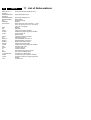
Content
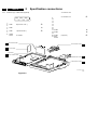
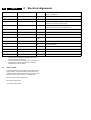
1. Technical specifications
2. Connection facilities, chassis overview
3. Safety instructions, maintenance,
warnings and Notes
4. Mechanical instructions
5. Service modes, DST, error messages,
protections, faultfinding and repair tips including:
Errorcodes-table
Protection-structure (overview and detailed)
Fault find tree
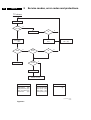
6. Block diagrams
Block diagram
(Supply, Deflection, CRT)
Block diagram
(Video, Audio, Control)
Survey of testpoints
Oscillograms
Wiring diagram
Overview I2C -ICs
Supply lines overview
2
3
5
7. Electrical Diagrams and PWB lay-outs
7
9
15
17
22
29
29
30
31
32
33
33
34
8.
9.
10.
11.
12.
Power Supply
(Diagram A1)
Line Deflection
(Diagram A2)
Frame Deflection / Frame Rotation (Diagram A3)
Audio Amplifier
(Diagram A4)
Mains switch Panel
(Diagram E)
CRT / Scavem Panel
(Diagram F)
Tuner, IF, I/O, Video processing (Diagram K1)
Input / Output
(Diagram K2)
Sound processing
(Diagram K3)
Audio Dolby
(Diagram K4)
Secam Correction
(Diagram U)
Featurebox 6 (Eco)
(Diagram K5)
Video control & Geometry
(Diagram K6)
Teletext & Control
(Diagram K7)
Side I/O Panel
(Diagram O)
Top Control Panel
(Diagram P)
DC Shift
(Diagram G)
Diversity tables
Electrical alignments
Circuit Descriptions: not available (see Training
Manual)
Directions for use
List of abbreviations
Spare parts list
Diagram
35
38
39
40
41
42
46
47
48
49
49
50
51
52
53
54
54
55
57
PWB
36,37
36,37
36,37
36,37
41
43
44,45
44,45
44,45
44,45
49
44,45
44,45
44,45
53
54
54
63
64
75
77
without
Subject
5
Published
Printed
Copyright
the
in
to The
reserved
by
modification
prior
CO
Netherlands
permision
9871
1998
TVPhilips
Service
of Philips.
Consumer
Department
Electronics B.V. Eindhoven, The Netherlands. All rights reserved. No part of this publication may be reproduced, stored in a retrieval system or transmitted, in any form or by any means, electronic, mechanical, photocopying,
4822
or 727
otherwise
21622
©Copyright reserved 1998 Philips Consumer Electronics B.V. Eindhoven, The
Netherlands. All rights reserved. No part of this publication may be reproduced,
stored in a retrieval system or transmitted, in any form or by any means, electronic, mechanical, photocopying, or otherwise without the prior permision of Philips.
Published by CO 9871 TV Service Department
Printed in The Netherlands
Subject to modification
5 4822 727 21622
2
MG2.1E
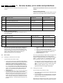
Mains voltage
1
Technical specifications
Aerial input impedance
Minimal aerial voltage
Maximum aerial voltage
Programmes
VCR programmes
1
Technical specifications
: 220V - 240V (± 10%);
50-60Hz (± 5%)
: coaxial 75 Ω
: 30µV (VHF), 40µV
(UHF)
: 180 mV
: 0-99
: 0, 90-99
2
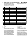
Specification connections
2.1
Specification connections
2
MG2.1E
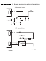
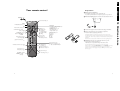
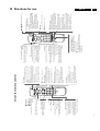
Front connections
5678-
TOP CONTROL FL7/FL8
STYLING
Blue
Audio
Blue
CVBSstatus
L (0.5Vrms ≥10kΩ)
(0.7Vpp/75Ω)
3
v
j
j
0-1.3V:INT
4.5-7V:EXT 16:9
3.5
SK 1
AUDIO R
AUDIO L
VIDEO
SVHS
AUTO TV
SENSOR
(OPTIONAL)
'IRRECEIVER'
'IR-SERVICE-LED'
91011121314-
BICOLOUR
STANDBY LED
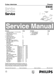
Figure 2-1
2.1.1
2.1.2
Audio/Video
- Video
- Audio
- Audio
1Vpp/75Ω
L(0.5Vrms ≥10kΩ)
R(0.5Vrms ≥10kΩ)
jq
jq
jq
- Headpho
ne
(32-600Ω ≥10mW)
ot
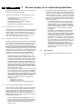
2.2
v
v
j
j
(1Vpp; 75Ω)
(0.3 Vpp;75Ω)
External 1(in/out): RGB+CVBS
(0.7Vpp/75Ω)
j
v
(0.7Vpp/75Ω)
v
j
0-0.4V:INT
(1Vpp/75Ω)
(1Vpp/75Ω)
v
v
k
j
External 2 (in/out): SVHS+RGB+CVBS (intended for VCR.)
Audio
Audio
Audio
Audio
Blue
Audio
Blue /
Chroma
out
8 - CVBSstatus
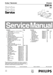
See figure 2.2
2.2.1
2.2.2
CVBS
CVBS
CVBS
CVBS
Earth
socket
1234567-
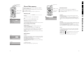
Rear connections
j
v
1-3V:EXT/75Ω
1718192021-
SVHS
123- Y
4- C
Green
Red
RGBstatus
15- Red
16- RGBstatus
CL 86532057_top.AI
310798
9.5-12V:EXT 4:3
Green
R (0.5Vrms ≤1kΩ)
R (0.5Vrms ≥10kΩ)
L (0.5Vrms ≤1kΩ)
L (0.5Vrms ≥10kΩ)
k
j
k
v
v
j
(0.7Vpp/75Ω)
j
0-1.3V:INT
4.5-7V:EXT 16:9
9.5-12V:EXT 4:3
L
91011121314-
EXTERNAL 1
Green
Red
RGBstatus
15- Red /
chromain
16- RGBstatus
EXTERNAL 3 (OPTIONAL)
R
AUDIO
Green
EXTERNAL 2
CL 86532057_rear.AI
310798
Figure 2-2
Easy link
(0.7Vpp/75Ω)
j
v
j
v
v
(0.7Vpp/75Ω)
j
(0-0.4V:INT
1-3V:EXT/75Ω)
1234-
Audio
Audio
Audio
Audio
R (0.5Vrms ≤1kΩ)
R (0.5Vrms ≥10kΩ)
L (0.5Vrms ≤1kΩ)
k
j
k
v
1718192021-
CVBS
CVBS
Y/CVBS
Y/CVBS
Earth
socket
(1Vpp/75Ω)
(1Vpp/75Ω)
v
v
k
j
4
2.2.3
2
MG2.1E
Specification connections
External 3 (in): CVBS+Audio (optional)
4.5-7V:EXT 16:9
j
9.5-12V:EXT 4:3
12345678-
F
Audio
R (0.5Vrms >10kΩ)
j
v
Audio
Audio
L (0.5Vrms>10kΩ)
CVBSstatus
0-1.3V:INT
j
9101112131415161718192021-
v
v
CVBS
CVBS
CVBS
Earth
socket
j
(1Vpp/75Ω)
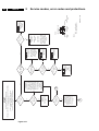
CRT/SCAVEM PANEL
TOP CONTROL PANEL
P
MAINSWITCH PANEL
E
LARGE SIGNAL PANEL
A
O SIDE I/O PANEL
SHIELDING
K
SMALL SIGNAL PANEL
CL 86532057_002.eps
170798
Figure 2-3
3
Safety instructions, Maintenance instruction,
3.1
Safety instructions, Maintenance instruction, Warnings and Notes
3
Safety instructions for repairs
–
–
–
1. Safety regulations require that during a repair:
– the set should be connected to the mains via an
isolating transformer;
– safety components, indicated by the symbol ∆, should
be replaced by components identical to the original
ones;
– when replacing the CRT, safety goggles must be worn.
2. Safety regulations require that after a repair the set must
be returned in its original condition. In particular attention
should be paid to the following points. h
– As a strict precaution, we advise you to resolder the
solder joints through which the horizontal deflection
current is flowing, in particular: ('general repair
instruction')
• all pins of the line output transformer (LOT);
• fly-back capacitor(s);
• S-correction capacitor(s);
• line output transistor;
• pins of the connector with wires to the deflection
coil;
• other components through which the deflection
current flows.
–
–
–
–
–
–
–
3.2
Note:
This resoldering is advised to prevent bad
connections due to metal fatigue in solder joints
and is therefore only necessary for television sets
older than 2 years.
The wire trees and EHT cable should be routed
correctly and fixed with the mounted cable clamps.
The insulation of the mains lead should be checked for
external damage.
The mains lead strain relief should be checked for its
function in order to avoid touching the CRT, hot
components or heat sinks.
The electrical DC resistance between the mains plug
and the secondary side should be checked (only for
sets which have a mains isolated power supply). This
check can be done as follows:
• unplug the mains cord and connect a wire between
the two pins of the mains plug;
• set the mains switch to the on position (keep the
mains cord unplugged!);
• measure the resistance value between the pins of
the mains plug and the metal shielding of the tuner
or the aerial connection on the set. The reading
should be between 4.5 MΩ and 12 MΩ;
• switch off the TV and remove the wire between the
two pins of the mains plug.
The cabinet should be checked for defects to avoid
touching of any inner parts by the customer.
Maintenance instruction
It is recommended to have a maintenance inspection carried
out by a qualified service employee. The interval depends on
the usage conditions:
3.3
MG2.1E
5
When the set is used under normal circumstances, for
example in a living room, the recommended interval is 3 to
5 years.
When the set is used in circumstances with higher dust,
grease or moisture levels, for example in a kitchen, the
recommended interval is 1 year.
The maintenance inspection contains the following actions:
• Execute the above mentioned 'general repair
instruction'.
• Clean the power supply and deflection circuitry on the
chassis.
• Clean the picture tube panel and the neck of the picture
tube.
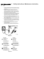
Warnings
1. In order to prevent damage to ICs and transistors, all highvoltage flashovers must be avoided. In order to prevent
damage to the picture tube, the method shown in Fig. 3.1
should be used to discharge the picture tube. Use a highvoltage probe and a multimeter (position DC-V). Discharge
until the meter reading is 0V (after approx. 30s).
2. ESD All ICs and many other semiconductors are
susceptible to electrostatic discharges (ESD). Careless
handling during repair can reduce life drastically. When
repairing, make sure that you are connected with the same
potential as the mass of the set by a wristband with
resistance. Keep components and tools also at this same
potential.
– Available ESD protection equipment:
– anti-static table mat (large 1200x650x1.25mm) 4822
466 10953
– anti-static table mat (small 600x650x1.25mm) 4822
466 10958
– anti-static wristband 4822 395 10223
– connection box (3 press stud connections, 1 M ohm)
4822 320 11307
– extension cable (2 m, 2 M ohm; to connect wristband
to connection box) 4822 320 11305
– connecting cable (3 m, 2 M ohm; to connect table mat
to connection box) 4822 320 11306
– earth cable (1 M ohm; to connect any product to mat or
connection box) 4822 320 11308
– complete kit ESD3 (combining all 6 prior products small table mat) 4822 310 10671
– wristband tester 4822 344 13999
3. Together with the deflection unit and any multipole unit, the
flat square picture tubes used from an integrated unit. The
deflection and the multipole units are set optimally at the
factory. Adjustment of this unit during repair is therefore not
recommended.
4. Be careful during measurements in the high-voltage
section and on the picture tube.
5. Never replace modules or other components while the unit
is switched on.
6. When making settings, use plastic rather than metal tools.
This will prevent any short circuits and the danger of a
circuit becoming unstable.
7. Wear safety goggles during replacement of the picture tube
6
3.4
3
MG2.1E
Safety instructions, Maintenance instruction,
Notes
1. The direct voltages and oscillograms should be measured
with regard to the tuner earth , or hot earth as this is called
(see fig. 3.3)
2. The direct voltages and oscillograms shown in the
diagrams are indicative and should be measured in the
Service Default Mode (see chapter 8) with a colour bar
signal and stereo sound (L:3 kHz, R:1 kHz unless stated
otherwise) and picture carrier at 475.25 MHz.
3. Where necessary, the oscillograms and direct voltages are
measured with and without aerial signal. Voltages in the
power supply section are measured both for normal
operation and in standby . These values are indicated by
means of the appropriate symbols (see fig. 3.3).
4. The picture tube PWB has printed spark gaps. Each spark
gap is connected between an electrode of the picture tube
and the Aquadag coating.
5. The semiconductors indicated in the circuit diagram and in
the parts lists are completely interchangeable per position
with the semiconductors in the unit, irrespective of the type
indication on these semiconductors.
6. Manufactured under license from Dolby Laboratories
Licensing Corporation.
7. DOLBY, the double D symbol and PRO LOGIC are
trademarks of Dolby Laboratories Licensing Corporation.
V
CL 26532098/042
140792
Figure 3-1
tuner earth
tuner aarde
la masse du tuner
Tuner-Erde
massa del tuner
tierra del sintonizador
hot earth
hete aarde
la terre directe
heißen Erde
massa calda
tierra caliente
with aerial signal
met antenne signaal
avec signal d'antenne
mit Antennensignal
con segnale d'antenna
con la señal de antena
without aerial signal
zonder antenne signaal
sans signal d'antenne
.ohne Antennensignal
senza segnale d'antenna
sin la señal de antena
normal condition
normaal bedrijf
fonctionnement normal
normaler Betrieb
funzionamento normale
funcionamiento normal
stand by
stand by
position de veille
in Bereitschaft
modo di attesa
posición de espera
Figure 3-2
4
Mechanical instructions
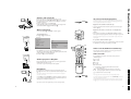
4.1
Mechanical instructions
4
MG2.1E
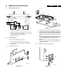
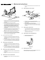
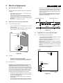
Removing the rear cover
A
7
Side I/O assembly
A
SSP - bracket
LSP - topbracket
A
A
LSP - bracket
1
2
A
A
1
Bottom tray
A
2
CL 86532042_002.AI
240798
or
A
A
or
A'
A
Figure 4-3
A
or
A
or
CL 86532042_001.AI
160798
Figure 4-1
1. Remove 1 screw in case of a 2-scart I/O coverplate and 2
screws in case of a 3-scart I/O coverplate (see figure 4.2).
2. Remove the I/O coverplate by releasing the snap at the left
side. Pull the I/O cover plate to the left and then backwards.
The I/O-bracket hinges at the right side. It can be removed
now.
3. Pull backwards (about 8 cm) the bracket with the SSP and
the LSP. These brackets are not fixed to each other, but
can be repositioned backwards, as if they were one
bracket.
4. Hook the brackets in the first row of fixation-holes of the
bottom tray; see figure 4.3. In other words re-position the
fixation from (1) to (2).
1. Remove the fixation screws (A) of the rear cover, notice
also the screw for the side-I/O, see figure 4.1. The screw A
is only valid for the 3-scart configuration.
2. Remove the rear cover.
4.2
Service positions
There are two predefined service positions:
1. Service position for the top side (component-side)
2. Service position for the bottom side (only valid for LSP)
(copper-side)
4.2.1
4.2.2
Service position bottom side (only for LSP)
Service position top side
CL 86532042_003.ai
090698
Figure 4-2
CL 86532042_005.ai
090698
Figure 4-4
8
MG2.1E
4
Mechanical instructions
2. Press the board upwards and remove the board from the
bracket.
4.6
Removing the top control board
Top control board
2
1
CL 86532042_006.ai
160798
CL 86532042_004.AI
240798
Figure 4-5
1. Referring to previous Service position one must remove
the SSP and LSP from bottom tray by pulling back these
two panels.
2. Disconnect the SSP from the LSP bracket.
3. The two panels must be shifted some 25 cm to the right.
When doing this the side-assembly can be taken out of the
hinge (see figure 4.4), and placed on the bottom tray.
4. Either the LSP-topbracket must be removed first, or the
cabling from SSP to LSP (0310 and O311) must be rerouted outside the LSP-topbracket to get room to position
these panels.
5. Turn the LSP 90 degrees anti clock wise and place the LSP
in the hole of the bottom tray. If needed a screw can
reinforce the stability of this position (see figure 4.5) (see
(2)).
6. The left front hook of the SSP panel can be fixed in a
fixation-hole, that was used in previous service-position for
the right front hook of the SSP. See described movementaction (1). (There is no right fixation hole.)
4.2.3
Figure 4-6
1. See figure 4.6. Pull 2 clamps to the outer side.
2. Top control board can be pushed down now, while it hinges
still in the front.
3. Now the board can be pulled backwards.
4. (If by accident the hinge in front is damaged or one of the
clamps is broken, the top control board can also be fixed by
2 screws.)
4.7
Removing the side I/O board
1. The complete Side I/O-assembly can be lifted out of the
hinges and placed on the bottom tray of the set (see fig
4.4).
2. The board can easily be removed out of the bracket by
releasing the fixation clamps.
4.8
Removing the mains switch/LED board
1. Release the two fixation clamps.
2. Pull the board backwards.
(Service position bottom side SSP)
1. (See figure 4.3). Remove the two fixation screws of the
LSP-topbracket (one on the left hand side, one on the right
hand side).
2. Disconnect wirings from cable-clamps of LSP-topbracket.
3. In case the line transformer is changed by a bigger type a
part of the LSP-topbracket can be removed by breaking it.
4.3
Removing the LSP-top bracket
(4) 5)
(
1. (See figure 4.3). Remove the two fixation screws of the
LSP-topbracket (one on the left hand side, one on the right
hand side).
2. Disconnect wirings from cable-clamps of LSP-topbracket.
3. In case the line transformer is changed by a bigger type a
part of the LSP-topbracket can be removed by breaking it.
86532093_002.AI
051198
Figure 4-7
4.9
4.4
Mounting the rear cover
Removing the SSP from SSP-bracket
1. Release the three fixation clamps on the right hand side of
the bracket.
2. Press the board upwards and remove the board from the
bracket.
4.5
(6)
(5) 4)
(
Removing the LSP from LSP-bracket
1. Release the two fixation clamps on the right hand side of
the bracket.
Before mounting the rear cover, check whether the mains cord
is mounted correctly in the guiding brackets.
5
Service modes, error codes and protections
5
Service modes, error codes and protections
5.1
In this chapter the following paragraphs are included:
5.1 Test points
5.2 Service modes and Dealer Service Tool and ComPair
(including fault finding tips related to CSM-mode)
5.3 Error codes
5.4 Protections
Fault find tree
Test points
The MG2.1E chassis is equipped with test points in the service
printing. These test points are referring to the functional blocks:
–
–
–
–
–
•
•
•
•
•
•
•
•
•
•
•
P1-P2-P3, etc.: Test points for the power supply.
L1-L2-L3, etc.: Test points for the line drive and line output
circuitry.
F1K-F2K-F3K, etc on Small Signal Panel: Test points for
the frame drive.
F1F-F2F-F3F, etc. on CRT/Scavem Panel: Test points for
the CRT-panel circuitry.
F1-F2-F3, etc. on Large Small Signal Panel: Test points for
the frame output circuitry.
S1-S2-S3, etc:
Test points for the synchronisation
circuitry.
V1-V2-V3, etc: Test points for the video processing
circuitry.
I1-I2-I3, etc: Test points for the Tuner/IF part.
A1-A2-A3, etc. on Small Signal Panel: Test points for the
audio processing circuitry.
A1-A2-A3, etc. on Large Signal Panel: Test points for the
audio amplifiers.
C1-C2-C3, etc: Test points for the control circuitry.
T1-T2-T3, etc: Testpoints for the teletext circuitry.
SC1-SC2-SC3, etc: Test points for the Scavem circuitry.
The numbering is done in a for diagnostics logical sequence;
always start diagnosing within a functional block in the
sequence of the relevant test points for that functional block.
5.2
–
Installation features for the dealer
The dealer can use the RC7150 for programming the TV-set
with presets. 10 Different program tables can be programmed
into the DST via a TV-set (downloading from the GFL, MD2 or
MG2.1 to the DST; see GFL, MD2 and MG2.1 service
manuals) or by the DST-I (DST interface; ordering code 4822
218 21277).
For explanation of the installation features of the DST, the
directions for use of the DST (4822 727 20073) are
recommended (for the MG2.1E chassis, download code 4
should be used).
5.2.2
Diagnose features for the servicer
The MG2.1E sets can be put in the two service modes via the
DST RC7150. These are the Service Default Mode (SDM) and
the Service Alignment Mode (SAM). The SDM and SAM can
also be entered by short circuiting the relevant pins on the SSP.
Service Default Mode (SDM)
Specification of the SDM:
By the "DEFAULT" key on the DST while the set is in the
normal operation mode.
By short-circuiting for a moment the two pins (pin 2 and 3
of connector 0356) on the component side of the SSP with
the indication "SDM" (activation can be performed in all
modes except when the set has a problem with the mainprocessor).
Exiting the SDM can only be done via the STANDBY
command. By switching off-on the set with the mains switch the
MG2.1E will come up again in the SDM.
Service Alignment Mode (SAM)
Specification of the SAM:
–
–
–
–
–
Software alignments (see chapter 8).
Option settings (see chapter 8).
Error buffer reading and erasing. The most recent error
code is displayed on the left side.
Operation counter.
Software version.
Entering the SAM can be done in 2 ways:
–
–
5.2.1
Tuning frequency 475.25 MHz.
TV-system for BGLM sets set to BG, for BGLL'I sets to LL'.
All picture settings at 50% (brightness, colour, contrast,
HUE).
All sound settings at 50% except volume at 25% (so bass,
treble, balance at 50%, volume at 25%).
All service-unfriendly modes are disabled (like sleep timer,
child lock, blue mute).
Note: If the SDM is entered via the pins, all the protections are
de-activated.
Service modes, Dealer Service Tool and ComPair
For easy installation and diagnosis the dealer remote control
RC7150 is introduced. The RC7150 can be used for all new TV
sets, including all set of the MG2.1E chassis. The RC7150 is
also called Dealer Service Tool or DST. The ordering number
of the DST (RC7150) is 4822 218 21232.
9
Entering the SDM can be done in 2 ways:
–
•
•
MG2.1E
By the > button on the DST while the set is in the normal
operation mode (or SDM). Enter the password '3-1-4-0'
and press OK.
By short-circuiting for a moment the two pins (pin 1 and 2
of connector 0356) on the component side of the SSP with
the indication "SAM" (activation can be performed in all
modes except when the set has a problem with the
microprocessor).
Note: If the SAM is entered via the pins, all protections are deactivated.
Exiting the SAM can be done via the MENU command or via
switching off-on the set with the mains switch.
Customer Service Mode (CSM)
All MG2.1E sets are equipped with the 'Customer Service
Mode' (CSM). This 'Customer Service Mode' is a special
service mode which can be activated and deactivated by the
customer upon request of the service technician/dealer during
a telephone conversation in order to identify the status of the
set. This CSM is a 'read only' mode, therefore modifications in
this mode are not possible.
Switching-on of the Customer Service Mode
The Customer Service Mode will switch-on after pressing
simultaneously the "MUTE" knob on the remote control
handset and the "MENU" button on the TV for at least 4
seconds. This activation only works if there is no menu on the
screen.
Switching-off the Customer Service Mode
The Customer Service Mode will switch-off after pressing any
key of the remote control handset (with exception of the
10
5
MG2.1E
Service modes, error codes and protections
"cursor-up" and "cursor-down" keys), or the buttons on the TV
or by switching off the TV set with the mains switch.
control handset after pressing the red button for picture menu
and selecting "contrast".
Detailed explanation of the Customer service Mode
After switching on the Customer Service Menu the following
screen will appear:
Line 7: LS Colour; gives the Last Status of the colour
saturation, as set by the customer. The value can vary from 0
(colour is minimum) to 63 (colour is maximum). Colour values
can be changed via "cursor left" and "cursor right" keys on the
remote control handset after pressing the red button for picture
menu and selecting "colour".
CUSTOMER SERVICE MENU 1
1
2
3
4
5
6
7
8
9
10
11
SW Version
Code 1
Code 2
LS Volume
LS Brightness
LS Contrast
LS Colour
LS Headphone
Sharpness
Dolby
Surround mode
............
... ... ... ... ...
... ... ... ... ...
..
..
..
..
..
.
.....
............
86532061_004.AI
230798
Figure 5-1 Customer Service Menu 1
Line 1: Software version; the build in software version
(AAAABCX.Y)
–
–
–
–
–
AAAA= MG21(chassis name)
B = E (Europe)
C = 1 (language cluster)
X = main version number
Y = sub version number
Details on the software version can be found in the chapter
"Software Survey" of the publication "Product Survey - Colour
Television".
Line 2: Code 1; gives the last 5 errors of the error buffer. As
soon as the built-in diagnose software has detected an error
the buffer is adapted.
Line 3: Code 2; gives the first 5 errors of the error buffer. As
soon as the built-in diagnose software has detected an error
the buffer is adapted.
The last occurred error is displayed on the leftmost position of
code 2. Each error code is displayed as a 3 digit number. When
less than 10 errors occur, the rest of the line(s) is(are) empty.
In case of no errors the text "No Errors" is displayed. See
paragraph 5.3 of this chapter for a description of the error
codes.
Line 8: LS Headphone; gives the Last Status of the headphone
volume, as set by the customer. The value can vary from 0
(volume is minimum) to 24 (volume is maximum). Headphone
volume values can be changed via the "cursor left" and "cursor
right" keys on the remote control handset after pressing the
green button for sound menu and selecting "headphone".
Line 9: Sharpness; gives the sharpness value. The value can
vary from 0 (sharpness is minimum) to 7 (sharpness is
maximum). In case of bad antenna signals a too high value of
the sharpness can result in a noisy picture. Sharpness values
can be changed via the "cursor left" and "cursor right" keys on
the remote control handset after pressing the red button for
picture menu and selecting "sharpness".
Line 10: Dolby; indicates whether the received transmitter
transmits Dolby sound (present) or not (not present). Attention:
The presence of Dolby can only be tested by the software on
the Dolby Signalling bit. If a Dolby transmission is therefore
received without a Dolby Signalling bit, then this indicator will
show "not present" even though such a Dolby transmission is
received.
Line 11: Surround Mode; indicates the by the customer
selected surround mode. In case the set is a Non-Dolby set
there will be displayed "0". If it is a Dolby-set then is displayed:
"Pro Logic", "Dolby 3 Stereo", "Hall" or "Off". For Dolby-set
surround mode can be changed via the "cursor left" and "cursor
right" keys on the remote control handset after pressing the
green button for sound menu and selecting "Surround
settings".
By means of the "cursor-down" knob on the remote control
handset the Customer Service Menu 2 will appear. By means
of the "cursor-up" knob on the remote control handset the
Customer Service Menu 1 will appear again.
Customer Service Menu 2 represents following information:
CUSTOMER SERVICE MENU 2
Line 4: LS Volume; gives the Last Status of the volume as set
by the customer for this selected transmitter. The value can
vary from 0 (volume is minimum) to 24 (volume is maximum).
Volume values can be changed via the volume key on the
remote control handset.
Line 5: LS Brightness; gives the Last Status of the brightness
as set by the customer for this selected transmitter. The value
can vary from 0 (brightness is minimum) to 63 (brightness is
maximum). Brightness values can be changed via the "cursor
left" and "cursor right" keys on the remote control handset after
pressing the red button for picture menu and selecting
"brightness".
Line 6: LS Contrast; gives the Last Status of the contrast as set
by the customer. The value can vary from 0 (contrast is
minimum) to 63 (contrast is maximum). Contrast values can be
changed via "cursor left" and "cursor right" keys on the remote
12
13
14
15
16
17
18
19
20
21
22
Rear Volume
Centre Volume
DNR
Noise Figure
Digital option
Colour System
TV System
Audio System
Tuned bit
Speaker config.
DVD
.
.
...
.
......
.....
.....
.....
.....
............
............
86532061_005.AI
230798
Figure 5-2 Customer Service Menu 2
Line 12: Rear Volume; gives the volume value of the surround
sound loudspeakers. This value can vary from 0 (minimum
volume) to 63 (maximum volume). Rear volume can be
changed via the "cursor left" and "cursor right" keys on the
remote control handset after pressing the green button for
5
Service modes, error codes and protections
sound menu, selecting "Surround settings" and selecting "Rear
volume". This feature is only available when surround mode is
in "Dolby Pro Logic" or "Hall".
Line 13: Centre Volume; gives the volume value of the centre
loudspeakers. This value can vary from 0 (minimum volume) to
63 (maximum volume). Centre volume can be changed via the
"cursor left" and "cursor right" keys on the remote control
handset after pressing the green button for sound menu,
selecting 'Dolby Pro Logic' and selecting "centre volume". This
feature is only available when surround mode is in "Dolby Pro
Logic" or "Dolby 3 Stereo".
Line 14: DNR (Dynamic Noise Reduction); gives the setting of
the DNR for the selected transmitter. The following selections
are possible:
•
•
"off", "min", "med" or "max"
"off" or "automatic" (MG2.1E with "Automatic Noise
Reduction").
The DNR can be changed via the "DNR" key on the remote
control handset.
Line 15: Noise Figure; gives the selected noise ratio for this
selected transmitter. This value can vary from 0 (good signal)
to 127 (average signal) and to 255 (bad signal). This only works
in case the DNR selection is "off/automatic".
Line 16: Digital Option; gives the selected digital mode,
"100Hz", Digital Scan" or "Natural Motion". Digital option can
be changed via the "cursor left" and "cursor right" keys on the
remote control handset after pressing the red button for picture
menu and selecting "digital options".
Line 17: Colour System; gives information about the colour
system of the selected transmitter.
–
–
–
–
Black and white: No colour carrier received
PAL: PAL signal received
SECAM: SECAM signal received
NTSC: NTSC signal received
Line 18: TV System; gives information about the video system
of the selected transmitter.
–
–
–
–
–
–
BG: BG signal received
DK: DK signal received
I: PAL I signal received
L: SECAM L signals received
M38.9: NTSC M signal received with video carrier on 38.9
MHz
MN: NTSC M signal received
Line 19: Audio System; gives information about the audio
system of the selected transmitter.
–
–
–
–
–
–
–
–
–
–
Sound Muted: No sound
Dolby Pro Logic: Dolby Pro Logic sound received
Mono: Mono sound received
Stereo: Stereo sound received
Dual I: Language I received
Dual II: Language II received
Digital Mono: Digital mono sound is received
Digital Stereo: Digital stereo sound is received
Digital Dual I: Digital language I is received
Digital Dual II: Digital language II is received
Line20: Tuned Bit; gives information about the tuning method
of the stored preset. If the value is "Yes" the preset is stored via
manual entry of the frequency when a transmitter was not
present on that frequency. In that case the TV will attempt to
perform a micro-search every time the preset number is
MG2.1E
11
selected. Once the micro-search has been successful the
Tuned Bit will be set to "No".
Line 21: Speaker configuration; gives the configuration setting
for the speakers. In case the set is a Non-Dolby set there will
be displayed "0". If it is a Dolby-set then is displayed: "Full
internal", "L/R external", "Surround external" or "Full external".
For the Dolby-set the speaker configuration can be changed
via the "cursor left" and "cursor right" keys on the remote
control handset after opening the installation menu and
selecting "set-up". The installation menu can be opened by
pressing "timer" and "enlarge" at the same time. This feature is
only available when the set has virtual Dolby.
Line 22: DVD; gives the configuration setting for DVD. This can
be "Present" or "Not Present". If "Present" is selected the
starting point is a top quality signal and a number of settings are
therefore changed automatically. DVD can be changed via the
"cursor left" and "cursor right" keys on the remote control
handset after opening the installation menu and selecting "setup". The installation menu can be opened by pressing "timer"
and "enlarge" at the same time.
Problems and solving tips
The procedures to change the value or the status of the
different settings is described in the paragraph 'Detailed
explanation of the Customer Service Mode'.
Picture problems
Worse picture quality in case of DVD pictures Check line 22
"DVD". In case line 22 gives the indication "Not Present"
change the setting into "Present".
Snowy/noisy picture
1. Check line 15 "Noise Figure". In case the value is 127 or
higher and the value is also high on other programs check
the aerial cable/aerial system.
2. Check lines 9 "Sharpness", 14 "DNR" and 15 "Noise
Figure". In case the value of line 9 is 3 or 4 and the value
of line 15 is high (127 or higher), lower the value of line 9
"sharpness" and switch DNR (line 14) to "automatic", "on"
or to a higher value.
Picture too dark
1. Press "Smart Picture" button on the Remote Control
handset. In case picture improves, raise the brightness
value or raise the contrast value. The new value(s) are
automatically stored for all TV channels.
2. After switching on the Customer Service Mode the picture
is OK. Raise the brightness value or raise the contrast
value. The new value(s) are automatically stored for all TV
channels.
3. Check lines 6 "LS Brightness" and 7 "LS Contrast". The
value of line 6 is low (<10) or the value of line 7 is low ((10).
Raise the brightness value or raise the contrast value.
Picture too bright
1. Press "Smart Picture" button on the Remote Control
handset. In case picture improves, reduce the brightness
value or reduce the contrast value. The new value(s) are
automatically stored for all TV channels.
2. After switching on the Customer Service Mode the picture
is OK. Reduce the brightness value or reduce the contrast
value. The new value(s) are automatically stored for all TV
channels.
3. Check lines 6 "LS Brightness" and 7 "LS Contrast". The
value of line 6 is high (>40) or the value of line 7 is high
((50). Reduce the brightness value or raise the contrast
value.
12
MG2.1E
5
Service modes, error codes and protections
Fading picture
Digital scan effect. Check line 14 "DNR". The status of "DNR"
is 'med' or 'max'. Reduce "DNR" to 'min' or switch off the digital
scan.
White line around picture elements and text
1. Press "Smart Picture" button on the Remote Control
handset. In case picture improves, reduce the sharpness
value. The new value(s) are automatically stored for all TV
channels.
2. After switching on the Customer Service Mode the picture
is OK. Reduce the sharpness value. The new value(s) are
automatically stored for all TV channels.
3. Check line 8 "Sharpness". Reduce the sharpness value.
The new value(s) are automatically stored for all TV
channels
Colours not correct/unstable picture. Check lines 17 "Colour
System" and 18 "TV System". In case line 17 is 'SECAM' and
line 18 is 'BG', the installed system for this preset is 'USA', while
'France' is required. Install the required program again. Open
the installation menu by pressing "timer" and "enlarge" at the
same time and perform manual installation. Select 'System;
France'.
Unstable picture. Check lines 17 "Colour System" and 18 "TV
System". In case line 17 is 'SECAM' and line 18 is 'M 38,9', the
installed system for this preset is 'West Europe', while 'France'
is required. Install the required program again. Open the
installation menu by pressing "timer" and "enlarge" at the same
time and perform manual installation. Select 'System; France'.
Menu text not sharp enough.
Blue picture. No proper signal is received. Check the aerial
cable/aerial system.
1. Press "Smart Picture" button on the Remote Control
handset. In case picture improves, reduce the contrast
value. The new value(s) are automatically stored for all TV
channels.
2. After switching on the Customer Service Mode the picture
is OK. Reduce the contrast value. The new value(s) are
automatically stored for all TV channels.
3. Check line 7 "LS Contrast". The value of line 7 is high
(>50). Reduce the contrast value.
Blue picture and/or unstable picture. A scrambled or decoded
signal is received.
Sound problems
No sound from left and right speaker.
Black and white picture. Check line 5 "LS colour". In case the
value is low ((10) raise the value of colour. The new value(s)
are automatically stored for all TV channels.
1. Press "Smart Sound" button on the Remote Control
handset. In case sound improves, raise the volume value.
The new value(s) are automatically stored for all TV
channels.
2. After switching on the Customer Service Mode the volume
is OK. Raise the volume value. The new value(s) are
automatically stored for all TV channels.
3. Check line 4 "LS Volume". The value is low. Raise the
value of "Volume". The new value(s) are automatically
stored for all TV channels.
No picture. Check line 20 "Tuned bit". In case the value is 'Yes',
install the required program again. Open the installation menu
by pressing "timer" and "enlarge" at the same time and perform
manual installation.
No colours/colour lines around picture elements.
1. Check lines 17 "Colour System" and 18 "TV System". In
case line 17 is 'PAL' and line 18 is 'M 38,9', the installed
system for this preset is 'USA', while 'West Europe' is
required. Install the required program again. Open the
installation menu by pressing "timer" and "enlarge" at the
same time and perform manual installation. Select
'System; West Europe'.
2. In case line 17 is 'PAL' and line 18 is 'L', the installed
system for this preset is 'France', while 'West Europe' is
required. Install the required program again. Open the
installation menu by pressing "timer" and "enlarge" at the
same time and perform manual installation. Select
'System; West Europe'.
No colours/noise in picture
1. Check lines 17 "Colour System" and 18 "TV System". In
case line 17 is 'Black and White' and line 18 is 'BG', the
installed system for this preset is 'West Europe', while
'USA' is required. Install the required program again. Open
the installation menu by pressing "timer" and "enlarge" at
the same time and perform manual installation. Select
'System; USA'.
2. In case line 17 is 'Black and White' and line 18 is 'L', the
installed system for this preset is 'France', while 'USA' is
required. Install the required program again. Open the
installation menu by pressing "timer" and "enlarge" at the
same time and perform manual installation. Select
'System; USA'
Colours not correct. Check lines 17 "Colour System" and 18
"TV System". In case line 17 is 'PAL' and line 18 is 'L', the
installed system for this preset is 'France', while 'West Europe'
is required. Install the required program again. Open the
installation menu by pressing "timer" and "enlarge" at the same
time and perform manual installation. Select 'System; West
Europe'.
Sound too loud for left and right speaker.
1. Press "Smart Sound" button on the Remote Control
handset. In case sound improves, reduce the volume
value. The new value(s) are automatically stored for all TV
channels.
2. After switching on the Customer Service Mode the volume
is OK. Reduce the volume value. The new value(s) are
automatically stored for all TV channels.
3. Check line 4 "LS Volume". The value is high. Reduce the
value of "LS Volume". The new value(s) are automatically
stored for all TV channels.
No sound from "centre" speaker. Check line 12 "Centre
Volume". The value is low. Raise the value of the "Centre
Volume"
Sound too loud from "centre" speaker. Check line 12 "Centre
Volume". The value is high. Reduce the value of the "Centre
Volume"
Diagnose Mode (only active during transmission of error
codes and diagnose 99)
This mode is activated by the DIAGNOSE command on the
DST for reading the error codes and erasing the error buffer by
the DST even when the set is in protection and so there is no
picture (assuming that the power supply and the control part
are working). For activation see paragraph 5.3. The diagnose
Mode is only a temporarily mode (the set will go back to the
previous mode), and can not be switched on permanently.
5
Service modes, error codes and protections
Note: The diagnose mode can not be entered if the SAM is
activated.
Compair
ComPair (Computer Aided Repair) is a service tool for Philips
Consumer Electronics products. ComPair is a further
development on the DST service remote control allowing faster
and more accurate diagnostics. ComPair has three big
advantages:
•
•
•
ComPair helps you to quickly get an understanding how to
repair the MG2.1E in short time by guiding you step by step
through the repair procedures.
ComPair allows very detailed diagnostics (on I2C level) and
is therefore capable of accurately indicating problem
areas. You do not have to know anything about I2C
commands yourself; ComPair takes care of this.
ComPair speeds up the repair time since it can
automatically communicate with the MG2.1E (when the
micro processor is working) and all repair information is
directly available. When ComPair is installed together with
the SearchMan MG2.1E electronic manual, schematics
and PCBs are only a mouse-click away.
ComPair consists of a Windows based fault finding program
and an interface box between PC and the (defective) product.
The ComPair interface box is connected to the PC via a serial
or RS232 cable. In case of the MG2.1E chassis, the ComPair
interface box and the television communicate with each other
via bi-directional infrared signal.
MG2.1E
13
Automatic information gathering
Step-by-step start up. Under normal circumstances, a fault in
the power supply or an error during start-up will switch the
television to protection-mode. ComPair can take over the
initialisation of the television. In this way it is possible to
distinguish which part of the start-up routine (hence which
circuitry) is causing the problem.
Reading out the error buffer, ComPair can automatically read
out the contents of the entire error buffer.
Diagnosis on I2C level. ComPair can access the I2C bus of the
television without a physical connection. ComPair can send
and receive infrared commands to the micro controller of the
television. These commands are translated by the controller to
I2C commands and vice versa. In this way it is possible for
ComPair to communicate (read and write) to devices on the I2C
busses of the MG2.1E.
Manual information gathering
Automatic diagnosis is only possible if the micro controller of
the television is working correctly and only to a certain extend.
When this is not the case, ComPair will guide you through the
fault finding tree by asking you questions and showing you
examples. You can answer by clicking on a link (e.g. text or an
oscillogram) that will bring you to the next step in the
faultfinding process.
A question could be: Do you see snow? (Click on the correct
answer)
YES / NO
An example can be: Measure testpoint I7 and click on the
correct oscillogram you see on the oscilloscope
I7 B7502
PC
VCR
Power
9V DC
I 2C
86532027_003.EPS
050898
1V / div DC
10µs / div
Figure 5-3
Figure 5-5
By a combination of automatic diagnostics and an interactive
question/answer procedure, ComPair will enable you to find
most problems in a fast and effective way.
o
10
0.3-0.6m
20
o
86532027_002.EPS
050898
Figure 5-4
The ComPair fault finding program is able to determine the
problem of the defective television. ComPair can gather
diagnostic information in 2 ways:
1. Communication to the television (automatic)
2. Asking questions to you (manually)
ComPair combines this information with the repair information
in its database to find out how to repair the MG2.1E.
Additional features
Beside fault finding, ComPair provides some additional
features like:
•
•
•
Uploading/downloading of presets
Managing of preset lists
Emulation of the Dealer Service Tool
SearchMan (electronic service manual)
When ComPair is installed in combination with SearchMan, all
schematics and PCBs will be directly available while you repair
a television if you click on a PCB or schematic link.
Example: Measure the DC voltage on C2568 (PCB/schematic)
on the small signal level.
Clicking on PCB will automatically pop-up a picture of the PCB
with the location of C2568 marked. Clicking on schematic will
14
MG2.1E
5
Service modes, error codes and protections
automatically pop-up the schematic with the location of C2568
marked.
Stepwise Startup /Shutdown feature of set can be used via
Compair
Stepwise startup explanation
Via ComPair the stepwise startup (see also chapter 4) can be
realised. This is very helpful when a protection is activated.
State
Description mode
Display leds
Errorcode possible
0
Low Power Standby/uC in Stby
Red on
None
1
High Power Standby/set in Stby
Red 0.5Hz
None
2
Supply on. Protections 5V2, 8V6, DC-Prot activated.
Orange/Green 0.25 Hz
67,68,76
3
ICs initialized. (Sound) Protection 3V3 activated
Orange/Green 0.5 Hz
plus 77
4
EHT startup. No blackcurrent stabilisation. Protections VFB,
HFB, LDP, BC-prot activated (blanked picture)
Orange/Green 2 Hz
plus 70,71,73,74
5
TV operates, unblanked picture
Orange/Green 10 Hz
Stepwise shutdown explanation
In the stepwise shutdown mode, state 2 is skipped. (ICs can
not be de-initialised).
State
Description mode
Display leds (Note *)
Prot. de-activated
5
TV operates, unblanked picture
Orange/Green 10 Hz
-
4
No blackcurrent stabilisation (no picture)
Orange/Green 2 Hz
-
3
ICs stay initialised. (Sound) All protections are off
Orange/Green 0.5 Hz
74,73,71,70
1
High Power Standby/set in Stby
Red 0.5Hz
77,76,68,67
0
Low Power Standby/uC in Stby
Red on
-
Note: When set is in stepwise-mode and due to stepping-up a
protection is activated, the set really will go into protection
(blinking red led). The set will not leave the stepwise-mode
however. By stepping up the set can be activated again, until
state X, where protection was activated. At state (X-1)
diagnostic measurements can be performed.
5.3
Error codes
5.3.1
Reading error codes from the error buffer
1. Press the "DIAGNOSE" key (in all modes except the
SAM)
2. Press "1" to view the last error detected.
3. Hold the DST 5 to 10 cm from in front of the stand-by
LED of the set (the IR-sending LED of MG2.1E is
located near the stand-by LED).
4. Press the "OK" key.
The error is represented by a 2 digit number. The 2 digits on the
DST are displayed sequentially, with a pause before it is
repeated. The digit after the pause is the 1st digit. If the display
reads 4 - 7, the error code is 47. To read other error codes,
press "DIAGNOSE" and one of the other digit keys. Note:
The error buffer can be read in 2 ways:
1. On the screen via the Service Alignment Mode (SAM). In
case picture is OK, the error buffer can be read the easiest
via the SAM. In the main menu of the SAM the last 10
different error codes occurred are displayed. The most
recent detected error code is displayed on the left side, so
e.g.: 0 0 0 0 0means no error codes present in the buffer
3 0 0 0 0means one error code present in the buffer; error
code 3 2 3 0 0 0 means two error codes present in the
buffer; error code 2 is the most recent, error code 3 is
detected before 2
2. On the display of the DST. If an error has been detected by
the MG2.1E chassis, the set might go into protection.
Without the presence of a picture the errors can be read by
the DST, as long as the main-processor is still active
(green LED continuous and red LED blinking fast (5Hz); in
case of red LED is blinking slow (1,25Hz) there is a mainprocessor problem). To transmit the errors from the TV to
the DST:
–
–
5.3.2
If the DST cannot communicate to the MG2.1E in a proper
way, ERROR 2 is shown in the display of the DST. Trying
again by changing the DST position a little bit might often
help.
If the error buffer of MG2.1E is empty, no errors are
displayed by the DST; the display remains blank.
Clearing the error buffer
The error buffer can be cleared in 2 ways:
1. In the SAM by selecting the item RESET ERROR BUFFER
in the main menu.
2. By the "DIAGNOSE 99" command of the DST (in all modes
except the SAM). Press the DIAGNOSE key on the DST,
followed by 9 and 9 and then >.
Note: When error buffer is full (10 codes), no new error can be
stored anymore. However of every error raised is monitored
5
Service modes, error codes and protections
how long it exists in the error buffer. When for any reason a
false raised error exists in the buffer, it will be deleted after 50
hours. If this error still is actual after 50 hours, it will be raised
again. In this way is safeguarded that history of error codes is
stored. Sometimes it is an option to first write down the error
MG2.1E
15
buffer content, reset the buffer, and look again which error
codes are generated by the set.
5.3.3
Error code table
Table 5-1 Error messages
Error
Device
Description
Defective
item
Diagram
Defective module indication
1
ST24E16
Non volatile memory
IC7008
K7
Control
2
ST24E32 or M24C32
Non volatile memory
IC7008
K7
3
SAA5800
OTC2.5 microprocessor/TXT
IC7003
K7
5
UV1316
Tuner
U1102
K1
Tuner
15
TDA9320H
HIP I/O-video processing
IC7501
K1
Chroma IF IO
20
TDA9330H
HOP video control/deflection processor
IC7300
K6
Video Controller
25
MSP3410D
ITT sound processor
I 7751
K3
Audio module
26
SAA7712H
SEDSP dolby processor
IC7770
K4
50
SAA4978H
Picnic
IC7609
K5
51
SAA4990H
Prozonic
IC7608
K5
I2C
Feature Box
65
Slow
bus blocked
fig 5.7
Slow I2C bus blocked
66
Fast I2C bus blocked
fig 5.7
Fast I2C bus blocked
67
Supply 5V
5V2
fig 5.6
+5 V Supply
68
Supply 8V
8V6
fig 5.8
+8V Supply
70
V fail protection
VFB
fig 5.9
A3/A2/K6
Vertical Flyback
71
H fail protection
HFB
fig 5.9
A2/K6
Horizontal Flyback
73
Line Deflection protection
LDP
IC7484
A2/K6
Line Deflection
74
Beam Current Protection
BC-PROT
TS7351
K6/K7
Beam Current
76
DC Sound protection
DC-PROT
TS7762
A4/A1
Sound Output
77
Feature box protection
FBX-PROT
fig 5.6
K4
+3V3 (FBX) Supply
Remark:If on the DST the text "ERROR 2" is displayed, this
means that the communication from the TV to the DST has
failed.
5.4
Protections
5.4.1
General
will increase, which results in a quick slow-down of the FFS
supply.
Two service-modes. To get a quick diagnoses the MG2.1E has
two service-modes implemented:
•
•
The MG2.1E "Protection Diagram" shows the structure of the
protection system. See protection diagram (fig 5.6).
One micro-processor. The MG2.1E has only one microprocessor (OTC) and it remains active during Standby. This
because power of the microprocessor and the attached
memory chip set is coming from the 3V3 supply, which is
derived from the 5V Standby-circuitry. So in both power-on as
in Standby-mode the microprocessor is connected to this
power supply. The micro processor controls the Standby-line
for switching on and off the main supply. In the standby-mode
or in the protection-mode the Standby-line will open the
contacts of relay 1002 via T7000 and T7001, this results in
switching off the mains input to the main supply (FFS). In the
mean time via T7550 the intensity of LED of the opto-coupler
The service default mode. Start-up of the set in a
predefined way.
The service alignment mode. In this mode items of the set
can be adjusted via a menu and with the help of test
patterns.
Both modes can be entered via the service connector on the
SSP (connector 0356) or via the DST (dealer service tool) or
via ComPair. The service alignment mode can not be entered
in Standby, the set has to be in normal operation.
Protection levels. If a fault situation is detected an error code
will be generated and if necessary the set will be put in the
protection-mode. The protection-mode is indicated by blinking
of the red LED. In some error cases the micro processor does
not put the set in the protection-mode. The error codes of the
error buffer can be read via the service-menu (SAM) or via the
service send-LED and the DST/ ComPair . The DST diagnose
functionality will force the set into the Service-standby, which is
16
MG2.1E
5
Service modes, error codes and protections
alike the usual Standby, however the micro-processor has to
remain in normal operation completely.
•
The protections of the MG2.1E can be divided in 4 groups ;
•
•
•
•
5.4.2
Protection from I2C-busses (Fast and Slow) or I2C-IC
errors (device errors).
Protection from the inputs on the OTC.
Protections from the status register of the HOP
(communicated via I2C-bus).
DC-protection (sound amplifiers) monitored on OTC.
•
Protection from the I2C bus (fig. 5.7)
In normal operation some registers of the I2C controlled ICs will
be refreshed every 200 msec. During this sequence three I2Cbusses and the I2C -ICs as well will be checked. The I2C
protection will take place if the SDA and SCL are whether short
circuited to ground or to each other. An I2C error can also
occur, if the power supply of the IC is missing.
5.4.3
Protection from the inputs on the OTC (fig.5.8)
If a protection is detected at an input of the OTC, all protection
inputs of the OTC will be scanned every 200 msec. for 5 times.
If the protection on one of the inputs is still activated after 1
sec., then the set will be put in the protection-mode. Before the
scanning is started a so-called ESD-refresh will be carried out
first, because the interrupt on one of the inputs may be caused
either by a FLASH or by ESD. As a FLASH or ESD can harm
the settings of some ICs, the HOP-HIP-ITT-EDRIC-TEA6417TEA6422-LTP-PICNIC and Tuner are initialised again to
ensure the normal picture and sound conditions of the set.
•
•
•
5.4.4
8V6 and 5V2 protection (see detailed figure 5.8). The
presence of the 8V6 and 5V2 is sensed by the OTC. If the
8V6 and 5V2 is not present, then an error code is stored in
the error buffer and the set is put in the protection-mode.
BC protection (Beam Current). (See detailed figure 5.8).
The beam current is measured by a circuit on the SSP. If
the beam current exceeds a certain reference level, then
via D6350 and T7351 the BC-input of the OTC is set to
high. The error code is stored in the error buffer and the set
is put in the protection-mode.
DC-protection. (Fig. 5.10) This is an urgent protection, the
circuitry is located at the LSP. The output of the protection
circuit will slow-down the FFS power supply immediately
via the opto-coupler and via the Standby-relay the supply
will be switched into Standby-mode at once. To be able to
store the error code in the error buffer the protection
signals are also wired to the OTC. The protection is
activated in case of :
– Unbalance of +Vs and -Vs
– Unbalance of +7V7 and -7V7
– DC output present on one of the audio amplifiers
Protections from the status register of the HOP (fig. 5.9)
Every 200 msec. the status register of the HOP is read by the
OTC via I2C. If a protection signal is detected on one of the
inputs of the HOP, then the relevant error bit in the HOP
register is set to 'high'. If the error bit is still 'high' after 1 sec.,
the OTC will store the error code in the error buffer and
depending on the relevancy of the error bit the set will either go
into the protection-mode or not.
•
HFB: Horizontal Flyback (See detailed figure 5.9). If the
horizontal flyback is not present, then this is detected via
the HOP. One status bit is set to 'high'. The error code is
stored in the error buffer and the set will go into the
protection mode
5.5
VFB: Vertical Flyback (See detailed figure 5.9). The HOP
will blank the screen , if the vertical flyback signals are not
present at the VFB-guard input .The relevant status bit will
be set in the register of the HOP. The error code is stored
in the error buffer, in this case protection is not necessary.
LDP-protection (Line Deflection Protection) (See detailed
figure 5.8). Two protection circuits are connected to the
LDP-input of the HOP :
1. Flash detection. From the EHT-info, via D6341 and
T7341 a flash will stop the H-drive and line output
stage immediately. The FLS-bit in the status register of
the HOP is set to 'high'. As the duration of a flash is
very short the FLS-bit will be reset to 'low' again after
the flash refresh, so via a slow start the set will be
started again.
2. LDP detection. The EW-protection, coming from the
line-output is also connected to the same input as
above. The current through the EW-stage is measured
by R3483 and R3484 on the LSP. The voltage across
these precision resistors will increase in case of a
failure at the line output stage. If the voltage becomes
higher than 1 V, then the output of IC7484 will become
'high' and remains 'high' via D6485 and R3490. Via
D6344 the H-drive will be stopped. The FLS-bit will be
set to 'high' and remains 'high' by means of the
software filtering even after a flash refresh. The OTC
will put the set in Standby-mode. The error code is
stored in the error buffer and the set gets into the
protection mode.
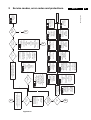
Fault find trees
See fault find trees at the end of this chapter. (figures 5.115.17)
5
3V3 St-by
5V2
(65) slow
OTC (3)
St-by
5V2
I/O video
I/O audio
Tuner
Picnic
Prozonic
FBX
(10)
(11)
(5)
(50)
(51)
(77)
Mainswitch
1050
Mains
(20)
(15)
(25)
(26)
(21)
6570
+5Vst-by
7021
8V6
5V2
+- (16V)
(67)
7000/
7001
7050
6052
5V2
(68)
green
red
6051
6571
IR
8V6
HOP
HIP
ITT
EDRIC
LTP
5Vst-by
St-by
IR
140V
DC prot
(76)
33V
tuner
FFS
AUDIO
FBCSO
BC (74)
I2C-F
6350 27V
7351
BC info
8V6
7438
6341 33V
7341
+
7484
RGB
Video control
-
1V
EHT info
E/W
Hor. defl.
HFB
200V
EHT
FIL
-13V
+13V
-15V
Vert. defl.
VFB
HFB
(71)
DEFLECTION
VFB
(70)
6758
HOP (20)
MG2.1E
I2C
LDP (73)
(66) fast
FBSCO
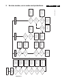
Figure 5-6
I2C-S
Protectionstructure MG2.1E
ST24E16 (1)
ST24E32 (2)
I2C3
Service modes, error codes and protections
NVM
CL 86532092_011.eps
031198
17
18
5
MG2.1E
Service modes, error codes and protections
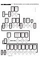
I2C drivers
Start
Start
cond. OK
N
Y
Free the bus
5X
N
Y
General I2C
error
Send adres
data
N
ACKN
Check
device
5X
Slow (65)
Fast (66)
N
Y
Bus
blocked
Stop
N
Y
Free bus
Device I2C error
Slow
1102 (Tuner)
(5)
(50)
7609 (Picnic)
7608 (Prozonic) (51)
7501 (I/O Video) (10)
Feature box
(77)
Fast
NVM-bus
7402 (LTP) (21)
7770 (Dolby) (26)
7751 (ITT) (25)
7501 (HIP) (15)
7300 (HOP) (20)
7008 (NVM) (1)
(2)
jsp 86532047_036.eps
261198
Figure 5-7
5
Service modes, error codes and protections
MG2.1E
E/W
E.W. drive
6480
10V
3483//
3484
6485
3490
HOP
3493
+
3491
6344 (5)
-
8V6
220K
1V
LDP
(73)
3492
33K
8V6
3340
6340
START/
STOP
H DRIVE
8V6
6341
EHT info
7341
FLASH
8V6
8V6
6350
OTC
3350
7351
(74)
27V
BC-prot
3352
3353
CL 86532092_013.eps
031198
Figure 5-8
19
20
5
MG2.1E
Service modes, error codes and protections
HFB horizontal fly-back
HOP
Hdefl
HFB
(71)
ϕ2
7421
5410
2420
Hdrive
3353
2419
VFB vertical fly-back
HOP
6758
ϕ2
VFB
(70)
27V
100µ
8V2
F
R
A
M
E
Vpos
Vneg
7600
Flyback
gen
PA
Thermal
prot
Vdefl
SM 86532047_039.eps
290798
Figure 5-9
Figure 5-10
µP
DCprot (76)
6570
6571
7556
5VST-by
7762
7001
7550
7761
7000
1002
7796
AUDIO
220V
Main
supply
FFS
-Vs
+Vs
-7V7
+7V7
Vbatt
8V6
5V2
+- Vs (16V)
S
2700
L
STANDBY + DC PROT
C
R
5
Service modes, error codes and protections
MG2.1E
SM 86532047_040.eps
290798
21
START
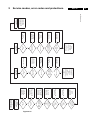
Figure 5-11
A
See Table with
error messages in
chapter 5 of this manual,
which device is causing
the error. Make a note of
the error messages.
Hereafter reset the error
buffer.
Yes
Are there Errors
indicated ?
Read Error
buffer with
Dealer Service Tool
(DST)
Yes
No
No
A
1
3
2
Check/Replace
(K7); D6073
TS7012
R3059
(E); LED6051
1
Yes
(K7); Anode of
D6037
0V?
Yes
(K7); 6MHz on
<C3> OK ?
Yes
(K7); RESET pulse
on <C1> OK ?
Yes
(A1); +5VSTANDBY
on <P4> OK ?
No
No
No
7
1
2
1
1
1
3
1
0
Check/Replace
(K7); IC7003
7
Check/Replace
(K7); X1001
7
Check/Replace
(K7) TS7006,TS7007,
TS7016
Note : If reset remains
low, then the set can
function normally.
If reset remains high,
then the set will not
function
1
No
1
1 A
4822 310 11235
STANDBY supply
repair kit
Repair STANDBY
Supply with:
Note 2:
1
1
1
1
1
1 A
A
Main symptom
code
1
MG21FFT1.VSD
(K1) means Drawing K1
<F11> means Test point F11
1
Extended symptom
code
Check/Replace
Mains input circuit:
Mains switch,
Fuse 1052
1
IRIS SYMPTOM CODE
Note 1:
Condition
code
If the STANDBY Supply
is OK now, but the set is
still not functioning
properly, then switch off
the mains and start all
over again
1
Yes
No
1
5
Does the LED
remain red
?
If the LED goes on
with the startup
sequence orange..green
then the set may seem
OK, however there are
also errors, which do not
result in a protection
state. At this point it is
adviceable to read out
the error buffer via the
DST to determine how
to continue with the
faultfinding.
So, read out the error
buffer with the DST
No
(A1); <P1>
OK ?
MG2.1E
Yes
Does the red LED
light
?
Connect a pattern generator to the aerial input.
Set Patt.gen. to 475,25 MHz, colourbar, stereosound, PAL B/G (for France SECAM L).
Put Mainsswitch : on
In normal conditions the set will start with the sequence :
red LED.., orange LED..,green LED.
Then after few seconds sound and picture will appear
22
Service modes, error codes and protections
Figure 5-12
B
Yes
Picture
OK ?
Yes
Does the screen
give any light or
picture ?
Put the set
in the SDMode
Previously the set was
switched off with the
mains button while the
set was in the Standby
mode
Yes
Green LED
OK
No
No
No
Starts with white
screen and
flyback lines,
then protection
and error 74
(F);
Check, +200D
+200A,R3373
L6373,C2370
1 3 4 4
1 3 1 X
Yes
Is the Heater
on ?
One of the colours is
leading
(F);
Check the B,G,R,drivers
IC7330,IC7340,IC7350
pin 8
The driver for the
leading colour has an
open output
1 4 2 2
Unstable picture,
no sync but
menuscreen is ok
Check/replace
(K1); X1525
1 3 5 1
No
Screen lights-up in
one colour with
flyback lines for one
second, then white
screen then prot. with
error 74
(F);
Check the B,G,R,drivers
IC7330,IC7340,IC7350
pin8
The driver for which
colour is lighting has a
short-circuited output
1 4 2 X
Menu-screen,picture
have poor contrast
check/replace
(K6); C2423,D6420,
TS7424
1 3 2 1
Check/Replace
(A2); R3466,
R3467,
L5466
Tracks to Heater
(F); R3380,
R3381,
L5380
R3387
1 3 1 0
Press the "P+" key on the RC
and observe if the LED goes on with the
startup sequence orange..green..
Check (F);
+12V,R3372,C2372,L6372,
D6335,D6345,D6355,
BLC-INFO,R3360,D6372
(K6); C2423,D6420,TS7424
(K5); TS7603,TS7604
If menu-screen is OK then check
(K5); IC7606(IC7614)
Put the Blue Mute option
"off" via the dealer mode
with the DST
Press the <P+> key on the set
and observe if the LED goes on with the
startup sequence orange..green..
A
1 3 5 1
Dotted-picture, no
sync and the menuscreen does not
appear
Check/replace
(K5); X1601
Rolling picture,but
menu-screen is OK
Check
(K5); VA at <S1>
1 3 5 1
F
Set is in the
Protection Mode
To ensure
communication with
the DST :
Check/Replace
(E);
D6053
TS7050
IR-LED D6052
R3063
R3064
Read the error code with
the DST and continue
with "F"
Protection Mode section
1 1 1 9
Yes
Poor contrast at
Dig.scan on,but menuscreen OK
check/replace
(K5); IC7607(IC7615)
No
Red LED is
Blinking ?
1 3 2 1
No Hor.sync,but
menu-screen is OK
Check
(K5); HA at <S2>
1 3 5 1
Switch off the mains
and start allover again at
the "START"
Press the yellow button
on the RC,
select Childlock and
switch to off.
This is a hidden mode,
which can be set/reset
via the user menu
The set is in
the Child Lock Mode.
Yes
Green LED
OK
C
Yes
1 3 5 X
Picture does not start
at the top,menuscreen does not
appear
check/replace
(K5); TS7605
Narrow/curved
picture
Check/replace
(K6); <S8>,
(A2); <L5>
,TS7480,D6480
1 3 3 5
No
(K7); <C2>
+3V3Standby
OK ?
Check/Replace
(K7); IC7009,
C2029
Service modes, error codes and protections
MG21FFT2gb.VSD
Only noise
check/replace
(K1); +33V,D6101
1 2 1 1
See VIDEO
Fault Finding Tree
One vertical line
Check
(A2); The Line output
circuit,conn.0317
1 3 3 A
No
1 1 1 9
5
MG2.1E
23
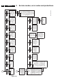
Figure 5-13
E
To ensure
communication with
the DST :
Check/Replace
(E);
D6053
TS7050
IR-LED6052
R3063
R3064
Yes
Error codes
indication ?
No
No
Check Option
numbers.
See sticker on CRT for
default options
Check/Replace
(K7); Conn.0356
D6012
R3005-C
1 1 3 4
Yes
OSD
OK?
See AUDIO
Fault Finding Tree
Check/Replace
(K7); TS7017, TS7018
Pin 77 : 80 of
IC7003 (OTC)
R3048-ABCD
(K6); Pin 35:38 of
IC7300(HOP)
1 1 3 4
Check/Replace
(K7 ); IC7002
IC7003
IC7008
IC7013
X1001
1 1 1 A
Yes
(A1); <P19>
= 141 V ?
No
Repair main Supply
with:
Main Supply
Repair Kit
4822 310 11234
If the power supply is ok
now ,but the set is still
not functioning properly,
then switch off the
mains and start allover
again at the "START"
1 3 4 4
Yes
(A1); IC7520
pin 1
16V<Vcc<18V
?
Yes
(A1); <P5>
300 V ?
No
Check/Replace
(A1); R3520
R3527,D6520
C2520,C2525
D6522
1 3 4 4
No
If the power supply is ok
now ,but the set is still
not functioning properly,
then switch off the
mains and start allover
again
Afterwards
remove
short of pin3,4
1 3 4 4
Check/replace
(A1); Relay 1002,
TS7000.
TS7001
Yes
(A1); <P5>
=300 V ?
Check
(A1); R3005
R3006
Short pin 3+4 of
Relay 1002
Yes
Fuse 1053
OK?
MG21FFT3gb.VSD
No
No
Repair main Supply
with:
Main supply
Repair Kit
4822 310 11234
If the power supply is ok
now ,but the set is still
not functioning properly,
then switch off the
mains and start allover
again
1 3 4 4
5
Yes
No
No
C
MG2.1E
SAM
on
screen ?
Put the set in the
Service Mode
via DST or service-pins
small signal panel (K7);
Conn.0356
Yes
Sound
OK ?
B
24
Service modes, error codes and protections
Figure 5-14
(K1,K3);
<I11>,<I12>
OK
?
Yes
(K3);
IC7751 pin20
=18,4 Mhz ?
Yes
(K3);
+5DA,+5DB
OK?
Yes
(A1); +5V2 <P18>
OK ?
Yes
(A4);
+7V7,-7V7 OK
?
Yes
(A1);
<P12>,<P13>
=
+Vs,-Vs ?
Check of the
Supply and X-tal
section
AUDIO
Fault Finding Tree
No
No
No
No
No
No
Check/replace
(K1); IC7501,TS7111
Check/replace
(K3); X1751
Check/replace
(K3); L5751,L5752
C2765,C2766
Check/replace
(A1); Fuse1201
D6223,C2222
IC7212,TS7214
Check/replace
(A4); C2791,C2792
IC6770,IC6767
D6768,D6769
C2783,C2784
Check/replace
(A1); Fuse1220,
Fuse1221,
C2220,C2221,
D6218-D6221
Yes
Check/replace
(A4); Conn. 0336
Conn. 0335
Speakers
Yes
(A4);
<A1>,<A2>
OK ?
Yes
(A4);
<A9>,<A10>
OK ?
Yes
(K3);
<A7>,<A8>
OK?
Yes
(K3);
IC7751pin61
high ?
Main audio section
No
No
No
No
Check/replace
(A4); IC7740
Check/replace
(K3); IC7756
Conn. 0328
Check/replace
(K3); IC7751
Check replace
(K3) ; TS7774
No
Check/replace
(K4); IC7750
C2819,C2816
C2818
Check/replace
(K3); Conn. 0344
Headphones
Yes
(K3);
<A14>,<A15>
OK ?
Yes
(K3);
<A20>,<A21>
OK?
Headphone section
No
No
Check/replace
(K4); IC7770
Yes
(K4);
+5DC,+3V3S,
+3V3SD
+3V3SA OK?
Check/replace
(K3); IC7757
No
Check/replace
(A4); Conn. 0337,
Conn. 0338
Speakers
Yes
(A4);
<A3>,<A4>
OK ?
Yes
(K4);
<A16>,<A17>
OK ?
Yes
(K3);
<I13>,<I14>,<I15>
OK ?
DOLBY section
(only for Dolby sets)
No
No
MG21FFT4gb.VSD
Check/replace
(K4); IC7750
Check/replace
(K3); IC7751
5
Service modes, error codes and protections
MG2.1E
25
Figure 5-15
Yes
(K1); +33V
OK?
Yes
(K1);
X1525, X1526,
X1527, X1528
OK ?
Yes
(K5); X1601
12MHz
OK?
Yes
(K6); X1305
12MHz
OK?
Yes
(K5);
+3V3M1,
+3V3M2
+3V3,+3A,+3D
+5VA,+5M,+5V2-FB
+5P OK?
No
No
No
No
No
No
Check/replace
(K1); D6101
(A1); R3567, R3569
Check/replace
(K1); X1525X1528
IC7501
Check/replace
(K5) X1601, IC7609
Check/replace
(K6); X1305, IC7300
Check/replace
(K5); IC7613
(A1); IC7212
Check/replace
(K6); R3300
(K1); R3538
(A1); IC7213
D6223, Fuse1201
Check/replace
(F); R3373
(A2); D6441,R3443
Check/replace
(F); R3372
(A2); D6460,
Fuse 1460
(K1);
V3a,V3b,V3c
OK?
Yes
(K1);
IC7501 pin14
CVBSINT
OK?
Yes
(K1); <I7>
OK?
Yes
(K1); <I2>
OK?
No
No
No
No
Check/replace
(K1); if COMB is
selected
TS7561, IC7560
TS7555
(K1)IC7501
Check/replace
(K1); TS7502
Check/replace
(K1); Fil 1108,Fil 1109
L5103,TS7101;
Change parameters
to selected input
conditions if possible.
If it is not possible then
replace IC7501
Check/replace
Antenna input
Tuner1 (1102)
Continue with the
Deflection and Sync.
Fault Finding Tree
Yes
CRT
OK ?
Yes
(F);
<F4f>,<F5f>,<F6f>
OK ?
Yes
(F);
<F1f>,<F2f>,<F3f>
OK ?
Check of the CRT
panel
Yes
(K6);
check pin 28,27,26 of
7300 (alike <F1k>,
<F2k>,<F3k>)
OK ?
Yes
(K6);
<F1k>,<F2k>,<F3k>
OK ?
Check of
the video output
section
HOP
Yes
(K5);
IC7609
pin23,25,26
V3a,V3b,V3c
OK?
No
No
No
No
No
No
Replace
CRT
Check/replace
(F); IC7330, IC7340
IC7350, D6335
D6345, D6355
VG2
Check (F) ; Conn. 0340
(K6) ; Conn. 0340
Check/replace
(K6); IC7402
Check Featureboxcircuitry
section again
Check/replace
(K5); TS7610, TS7611
TS7612
(K7);
<T11>,<T12>,<T13>,
<T14>
OK?
Yes
(K7); <T16> OK ?
Select a program with
TXT and switch to txt
Check of the TXT
section
Replace
(K7); IC7003 OTC
IC7001
GO TO
Check of
the Video input section
HIP
MG21FFT5gb.VSD
No
No
5
(K6); +8VS,+8VR
(K1); +8VA,+8VB
OK?
No
No
Check of
Video input section
HIP
Check of the
Featurebox section
PICNIC
MG2.1E
Yes
(F); +200A
OK?
Yes
(F); +12V
OK?
Check of the
Supply and X-tal
section
Video
Fault Finding Tree
26
Service modes, error codes and protections
Figure 5-16
No
No
No
No
No
No
No
Check/replace
(K1); X1525X1528
IC7501
Check/replace
(K5); X1601, IC7609
Check/replace
(K6); X1305, IC7300
Check/replace
(K5); IC7613
(A1); IC7212
Check/replace
(K6); R3300
(K1); R3538
(A1); IC7213
D6223, Fuse 1201
Check/replace
(F); R3373
(A2); D6441, R3443
Check/replace
(F); R3372
(A2); D6460,
Fuse 1460
Check/replace
(A2);
<L1>,<L2>,<L3>,<L4>,
TS7408,TS7409,
TS7411,TS7421
T5430
(If too difficult:
line repair kit
4822 310 11236)
Yes
(K6); <S7> OK?
Yes
HA on (K5) and
<F5k> on ( K6) must
be synchronized
Yes
(K 6) ; <F5k> OK ?
Yes
(K5); HA available at
IC7609 , pin 28 ?
Yes
(K1); <S2>
OK?
Horizontal
drive section
No
No
No
No
No
Check/replace
(K6); IC7300
If not then (K5); IC7609
is defective
(K5); IC7609
defective
Check tracks from
(K1); IC7501 to
(K5); IC7609 .
(K1); replace IC7501
Check/replace
(A3); +13V-LOT
-15V-LOT
<F1>,<F2>,<F3>
D6614,C2615
D6617,D6618
IC7600
Yes
(K6);
<S5>,<S6>,<S8>
OK?
Yes
VA on (K5) and
<F4k> on (K6) must
be synchronized
Yes
(K6) ; <F4k> OK ?
Yes
(K5) ; VA available at
IC7609 , pin 29 ?
Yes
(K1); <S1>
OK?
Vertical
drive section
No
No
No
No
No
Check/replace
(K6); IC7300
If not then (K5); IC7609
is defective
(K5); IC7609
defective
Check tracks from
(K1); IC7501 to
(K5); IC7609 .
(K1); IC7501 HIP
defective
MG21FFT6gb.VSD
Check/replace
(A2); TS7480, D6479
C2480, C2482,
R3483, R3484
EW
drive section
Service modes, error codes and protections
Yes
(K1);
X1525, X1526,
X1527, X1528
OK?
Yes
(K5); X1601
12MHz
OK?
Yes
(K6); X1305
12MHz
OK?
Yes
(K5);
+3V3M1,
+3V3M2
+3V3,+3A,+3D
+5VA,+5M,+5V2-FB
+5P OK?
Yes
(K6); +8VS,+8VR
(K1); +8VA,+8VB
OK?
Yes
(F); +200A
OK?
Yes
(F); +12V
OK?
Check of the
Supply and X-tal
section
Deflection and Sync.
Fault Finding Tree
5
MG2.1E
27
.
7
Figure 5-17
NOTE: The protection
mode can be overruled
by putting the set into
the SDMode. This
should be done very
carefully, because of
the risk to damage the
parts which the
protection has been
designed for !!!
Overruling can only be
done by
shortcircuiting pin 2,3
of conn.0356
"PROTECTION
MODE"
1 1 1 A
7
2
0
The Slow I 2C bus does
not function.
Isolate the I 2 C
pins of the IC's one by
one until the system
gives any different
reaction or another error
indication. The IC with
the isolated I 2 C pins at
that moment should be
checked or replaced.
The following devices
are connected to the
Slow I2C bus :
(K1); U1102,IC7501
(K5); IC7608,IC7609
1 7
ERROR 65
5V2 failure
Overrule the protection
mode with the SDMode
carefully and check the
5V2 circuitry / load
ERROR 67
Check/Replace
(K1); U1102
1 2 1 0
ERROR 5
8V6 supply failure
Overrule the protection
mode carefully with the
SDMode and check the
8V6 circuitry / load
ERROR 68
Check/Replace
(K7); IC7501
See also the Video Fault
Finding Tree : Check of
the Videoinput section
HIP
1 3 3 X
ERROR 15
Vertical Flyback failure
Check/Replace
(A3) ;IC7600
See also the Deflection
and Sync. Fault Finding
Tree : Vertical drive
section.
ERROR 70
Check/Replace
(K6); IC7300
See also the Video Fault
Finding Tree : Check of
the Video output section
HOP
1 3 3 X
ERROR 20
Horizontal Flyback or
Line Deflection failure
Check/Replace
(A2) ;TS7421, Line
output circuit, LOT5430
See also the Deflection
and Sync. Fault Finding
Tree : Horizontal drive
section.
ERROR 71,73
note : due to
protection level
error 73 may not
occur, instead
error 71 will
always occur .
Check/Replace
(K3); IC7751
See also the Audio Fault
Finding Tree : Check of
the Main audio section
1 5 3 X
ERROR 25
Beam Current failure
Check/Replace
(F) ;+200D,+200A,
R3373,L6373,C2370
R3360,D6372
ERROR 74
Check/Replace
(K4); IC7770
See also the Audio Fault
Finding Tree : Check of
the DOLBY section
1 5 7 X
ERROR 26
Feature box failure
Check
(K5); +3V3(FBX)Supply
ERROR 77
DC sound protection
(A4); Isolate the output
pins(4,6) of IC7740,
IC7750 and go to the
Audio Fault Finding Tree
for further diagnose
ERROR 76
Check/Replace
(K5); IC7609
See also the Video Fault
Finding Tree : Check of
the Featurebox section
PICNIC
1 3 3 X
ERROR 50
2 0
MG21FFT7gb.VSD
The Fast I 2 C bus does
not function.
Isolate the I 2 C
pins of the IC's one by
one until the system
gives any different
reaction or another error
indication. The IC with
the isolated I 2 C pins at
that moment should be
checked or replaced.
The following devices
are connected to the
Fast I2C bus :
(K6); IC7300,IC7402
(K1); IC7501
(K3); IC7751
(K4); IC7770
1 7
ERROR 66
Check/Replace
(K5); IC7608
See also the Video Fault
Finding Tree : Check of
the Featurebox section
PICNIC
1 3 3 X
ERROR 51
5
THE NEXT
FOLLOWING ERROR
CODES RESULT THE
SET GOES INTO THE
PROTECTION MODE
.
Check/Replace
(K7); IC7003
1 7
ERROR 3
MG2.1E
F
Check/Replace
(K7); IC7008
1 7
ERROR 2
E
28
Service modes, error codes and protections
8
Electrical alignments
8.1
Electrical alignments
8
MG2.1E
General alignment conditions
All electrical alignments should be made under the following
conditions:
–
–
–
–
Power supply voltage: 220-240V ± 10%; 50-60 Hz ± 5%.
Warm-up time >10 minutes.
Voltages and oscillograms are measured in relation to
tuner earth (with exception to the voltages on the primary
side of the power supply). Never use the cooling fins/plates
as ground.
Test probe: Ri > 10 MOHM, Ci < 20 pF.
8.2
Alignments on the large signal panel (LSP)
8.2.1
+141V (VBAT) supply voltage
–
–
–
–
6, blue pin 11) and measure for each cathode the DC level
of the measuring pulse (see elucidation above and Fig. 8.2)
and write down each value. Remark: Trigger the scope
external via a CVBS signal (for instance via pin 19 of the
scart1 connection).
Adjust the Vg2 potentiometer (diagram A1, lower knob on
the LOT) so that the measuring pulse with the highest
noted level is on 160V level.
MEASURING PULSE 1
Connect a voltmeter across C2569 (diagram A1, +VBAT).
Switch on the set.
Using potentiometer R3559 (diagram A1) adjust the VBAT
supply voltage to +141V ± 0V5. (see Fig. 8.1)
3559
+V BAT
Figure 8-2
8.3
Alignments on the small signal panel (SSP)
8.3.1
40.4 MHz neighbour-channel sound trap
–
–
–
LOT
Tune to a checker board test-pattern (system BG - and with
a carrier frequency of 475.25 MHz).
Connect an oscilloscope (trigger line frequent) to pin 19
(CVBS out) of the scart1 connection.
Align the coil L5103 (diagram K1) completely downwards
(see Fig. 8.3).
Align the coil upwards till under- and overshoot arise at the
black/white and white/black transitions in the video signal
(Fig. 8.4).
Align the coil downwards again till above mentioned underand overshoot is just disappeared.
SSP
0356
CL 86532057_004b.AI
240798
1
2
3
SAM
SDM
Figure 8-1
Focusing
–
–
Tune the set to a cross hatch test-pattern.
Adjust the focus potentiometer (diagram A1, upper knob on
the LOT) for an overall optimum focusing of the picture.
Vg2 adjustment
Elucidation: In the frame blanking period of the R, G and B
signals applied to the CRT, alternately per frame two
measuring pulses with different DC levels are inserted by the
"HOP" video processor IC7300. During the first frame flyback a
pulse is inserted used as reference for the Vg2 adjustment and
in the next frame flyback a second pulse is inserted used as
reference for the internal white "D" adjustment. For the Vg2
adjustment the pulse with the highest DC-level is used.
–
–
–
Put the set in the SDM mode (via the >-button on the DST,
or via short circuiting the SDM pins 2 and 3 of connector
0356 on the SSP (diagram K7).
Insert a black test-pattern signal (carrier 475.25 MHz) to
the tuner input.
Connect an oscilloscope (position 50V/Div DC and 2ms/
Div) alternately to the CRT cathodes (red pin 8, green pin
0V
CL 86532092_012.eps
031198
–
Focus
Screen
VG2
ADJUST
LEVEL
10ms
–
8.2.3
MEASURING PULSE 2
Vco
LSP
8.2.2
57
L5103
40.4 MHz
ALIGNMENT
Tuner
CL 86532057_004a.AI
240798
Figure 8-3
58
8
MG2.1E
Electrical alignments
can be aligned. Alignment is correct when DC-voltage is just
below 3.8 V
8.5
Alignments and settings in the Service Alignment
Menu
8.5.1
General
Entering the SAM can be done in 2 ways:
•
CL 86532057_006.AI
170798
Figure 8-4
8.4
Alignments needing SAM-mode + measuring
equipment
(These alignments could be of interest when ICs (7501,
TDA9320H ), or the EAROM (7008, ST24E16) are exchanged
on the SSP.)
8.4.1
'IF AFC' (navigation to this menu item via Alignment -->
General--> IF AFC)
Supply via a Service generator (e.g. PM5518) a TV-signal, with
a signal-strength of about 1 mV. Preferable this signal is a
multiburst signal. Frequency 475.25 MHz. Use BG if possible,
otherwise match the system of your generator with the received
signal in the set. In this procedure Servicer will be asked to
swap sometimes from Install-menu to Service Alignment
Menu. Procedure how to check correct alignment:
–
–
–
First set the frequency of the TV-set to 475 MHz in the
'search-line' of the Manual Installation Menu
If the IF-frequency-value in the 'Fine Tune'-line is between
475.18 MHz and 475.31 MHz, you do not need to re-align
the AFC-value as mentioned above (SAM-menu).
If this is NOT the case, decrease the 'IF AFC'-value (in the
SAM-menu) if the frequency on the 'Fine-tune'-line was
lower than 475.18 MHz, or increase the 'IF AFC'-value if
the frequency on the 'Fine-tune'-line was higher than
475.31 MHz (initially first an 'IF AFC'- alignment can be
done, making the multiburst signal flat). This signal can be
measured at pin 19 of SCART 1. This is, however, not
accurate enough to optimise the 'IF AFC'.
Alignment procedure:
–
–
–
–
–
–
Set 'IF AFC'-value in SAM.
Store in SAM this setting.
Go to manual install menu.
Set frequency to 475 MHZ.
Read in 'Fine tune'-line how set responds.
If this value is between 475.18 MHz and 475.31 MHz then
OK, otherwise proceed alignment by setting an other 'IF
AFC'-setting.
Service-tip: If you do not trust the accuracy of the frequency of
your Service-generator, first 'measure' with 'Fine tune'-line
(manual install-menu) of a good set your Service generator.
8.4.2
'Tuner AGC'
•
The Service Alignment Mode menu will now appear on the
screen. The following information is now displayed:
1. The software date ('Date') and version ('ID.') of the ROM
(Example: MG21E11.0_01501). (This software-code
stands for MG21 (chassis), E for Europe, 1-language, 1.0
software version, xxxxx latest 5 digits of 12nc code
software.)
2. The accumulated total of operation hours ('Operation
Hours').
3. ('Errors') followed by maximal 10 errors. The most recent
error is displayed at the upper left. For explanation errors
see chapter 5 (table 5.1).
4. ('Defect. Module'). Here the module that generates the
error is displayed. (If there are multiple errors in the buffer
that have not all been generated by a single module, there
is probably another defect. The message 'Unknown' will
then be displayed here).
5. ('Reset Error Buffer'). The error buffer can be reset by
pressing the > key.
6. ('Functional Test'). All devices are tested via the > key.
Eventual errors are displayed in the error buffer. The error
buffer is not erased, the contents return when the
Functional Test is terminated.
7. ( 'Alignments'). This enables the Alignments sub-menu to
be called up.
The following alignments can be selected:
'General':
–
–
–
–
–
–
–
–
'Drive'
'Peak White Limiter'
'Luminance Delays'
'EHT Compensation'
'Soft Clipper'
'Luma Gain'
'IF AFC'
'Tuner AGC'
'Normal Geometry':
–
General geometry alignments.
'Super wide geometry': (only valid for widescreen sets)
–
Supply a TV-signal, with a frequency of 475.25 MHz and a
signal-strength of about 2 mV.
Measure the DC-voltage on pin 1 of the Tuner (position 1102).
With the 'Tuner AGC'-alignment in the SAM-menu, this voltage
Briefly shorting the service pins 'SERVICE ALIGNMENT
MODE' on the front side of the SSP (pins 1 and 2 of
connector 0356) or:
Pressing the > key on the Dealer Service Tool (DST)
(RC7150), followed by keying in the password "3140" and
then pressing the > key.
Geometry alignments for the 'Panorama' position in 16:9
sets (only valid for wide screen sets; alignments can be
performed, however, it is better to set values as mentioned
below).
'Options':
–
Setting the initialisation codes in the set via text.
8
Electrical alignments
'Option number':
–
All options together, expressed in two long numbers. The
original factory setting for these numbers can be found on
the picture tube sticker on the inside of the set.
MG2.1E
29"
10
32"
10
'Luminance delays'
With the 'Luminance delays' alignment the luminance
information is placed on the chrominance information
(brightness is pushed onto the colour). Use a colour bar/grey
scale pattern as test signal.
'Store':
–
Store all alignments.
The alignments are explained now in the sequence of the submenu:
8.5.2
•
General alignments in Service Alignment Menu:
•
•
•
•
59
•
Once all alignments/settings have been completed the
item 'Store' must be selected to record all the values in the
permanent memory of the set.
If the option codes have been changed and stored, the set
has to be switched on and off using the mains switch to
activate the new settings (when switching on and off via
Standby, the option code settings are NOT read by the
microprocessor).
If an empty EAROM (permanent memory) is detected, all
settings are set to pre-programmed default (standard)
values.
A built-in test pattern can be called up in various submenus. The test pattern generator can be switched on
using the item 'Test pattern on/off'. The test pattern only
appears AFTER the specific alignment has been selected.
The test patterns are generated by the teletext-IC.
•
Lum. Delay Pal: Apply a PAL colour bar/grey scale pattern
as a test signal. Adjust 'Lum. Delay Pal' until the transients
of the colour part and black and white part of the test
pattern are at the same position.
Lum. Delay Secam: Apply a SECAM colour bar/grey scale
pattern as a test signal. Adjust 'Lum. Delay Pal' until the
transients of the colour part and black and white part of the
test pattern are at the same position.
Lum. Delay Bypass: Apply a NTSC colour bar/grey scale
pattern as a test signal. Adjust 'Lum. Delay Bypass' until
the transients of the colour part and black and white part of
the test pattern are at the same position.
'EHT compensation'
Fixed value:
0
'Soft clipper"
Fixed setting: 'Pwl+0%'
'Luma gain'
Fixed value:
'Drive'
Tint-settings:
1
'IF AFC'
See chapter 8.4.1. The SAM-mode is needed to make
alignment, a test generator to make signal, an oscilloscope to
measure at SCART-output and the Install-menu to check finetuning-value.
Set the white levels for the three tint-settings 'Normal' . 'Warm'
and 'Cool' is calculated by the processor then ('Warm': R+4, B7 and 'Cool': R-3, B+3) For 4:3 picture tubes (25" and 29") the
next values must be entered:
'Tuner AGC'
See chapter 8.4.2. The SAM-mode is needed to make
alignment, a test generator to make signal, a DC-Voltmeter to
measure at pin 1 of Tuner.
Cool
Normal
Warm
R
22
25
29
G
20
20
20
Geometry alignments 'Normal Geometry' in the Service
Alignment Menu
B
17
14
7
Warning:
'Cathode':
This alignment must also be covered by a table with values for
all picture-tube sizes. For 4:3 picture tubes (25" and 29")
following value must be entered: 5
For wide screen picture tubes (24", 28" and 32") following value
must be entered:2
'Peak White Limiter'
Dependent of the picture-tube size (25", 29", and 24"/28"/32"
widescreen tubes) the next value of the table must be entered:
8.5.3
At this moment the INTERNAL test pattern of the set will lead
to a misaligned geometry of the picture. Please do not use
internal test pattern. When using a service generator with a
geometry-pattern (e.g. a crosshatch-pattern), the set can be
aligned without problems.
Vertical amplitude and centring
Select 'Test Pattern on' and set the begin conditions for 4:3
sets (25", 28" and 29"):
–
Vertical S-correction value on 13 for 29"-set, and on 19 for
the 25"- and 28"-sets.
24"
10
The boundary-stripes of the test pattern should be positioned
on the edge of the picture tube. Set the begin conditions for
16:9 sets (24", 28", 32"):
25"
10
–
28"
10
Vertical S-correction value on 7 for 24"-set, on 8 for the 28"
and on 7 for the 32"-set.
The boundary-stripes of the test pattern should be positioned
on the edge of the picture tube.
60
MG2.1E
8
Electrical alignments
1. Align 'V slope' (when aligning the below half of the picture
is blanked). The middle line of the test pattern must be
matched with the edge of this blanking/picture transient in
the middle of the picture. Pushing > button again, gives you
previous menu again. (This alignment is meant to align the
zero-crossing of the frame-deflection to the mechanical
middle of the picture tube.)
2. Align the vertical amplitude using 'V amplitude' so that the
test pattern is fully visible.
3. Align the vertical centring using 'V shift' so that the test
pattern is located vertically in the middle.
4. If necessary repeat the alignment of 'V amplitude', in order
to get 'V shift' OK.
Vertical S correction
Select 'Test pattern on'. Align the vertical S correction using 'V
S-correction' so that the vertical amplitude at the top of the
picture is equal to the amplitude in the middle of the picture.
Horizontal centring and amplitude
Select 'Test pattern on'.
1. Using 'H amplitude' align the horizontal amplitude so that
the entire test pattern is visible.
2. Use an external test signal, with a centre-reference from a
service-generator. Use 'H shift' to align the picture
horizontally in the middle.
3. Repeat the 'H amplitude' alignment if necessary.
East/west alignment
Select 'Test pattern on'.
1. Use 'East/West Parabola' to align the vertical lines until
straight.
2. Use 'East/West Corner' to align the vertical lines in the
corners until straight.
3. Use 'East/West Trapezium' to align for a rectangular.
4. Use 'Horizontal Parallelogram' to align for straight vertical
lines if necessary.
5. If necessary select 'East/West Corner' and align as
required.
6. Repeat steps 1 to 4 if necessary.
8.5.4
Geometry alignments 'Super wide geometry' in the Service
Alignment Menu
Only applicable to 16:9 sets. The header of this paragraph and
also the menu's are misleading. We only need to set the
following values, if the normal geometry alignment has been
performed correctly.
–
–
–
8.6
Vertical S correction: enter value here of normal geometry.
Horizontal amplitude: enter value here or normal geometry
subtracted by 4.
East/west parabola: enter value here or normal geometry.
Option menu
Introduction:
The microprocessor communicates with a large number of I2CICs in the set. To ensure good communication and make digital
diagnosis possible, the microprocessor has to know which ICs
have to be addressed. The presence of specific ICs or
functions is made known by means of the option codes.
All options codes can be manipulated using both the option
numbers and/or the Option menu.
All hardware related options are incorporated under the
heading 'Options' of the 'Alignments' sub-menu of the 'Service
Alignment Mode'. All software related options that are
incorporated under the heading 'Dealer Options' of the 'Service
Alignment Mode'', can also be reached directly via the '>button
of the DST.
8
Electrical alignments
8.7
Options in the Service Alignment Mode
MG2.1E
61
Menu-item
Subjects
Options
Physically in the set
Teletext
TXT
Yes
Teletext present
No
Teletext not present
Yes
Easylink set
No
Easylink not set
4:3
4:3 picture tube
16:9
16:9 picture tube
Yes
rame rotation circuitry present on LSP (IC7440 diagram A3)
No
Frame rotation circuitry not present (IC7440 diagram A3)
100Hz
IC7606present on SSP (diagram K5)
Digital Scan
IC7606 and IC7607present on SSP (diagram K5)
Yes
IC7560 present on SSP (diagram K1)
No
IC7560 not present on SSP (diagram K1)
Yes
In normal operation: Yes
No
During 'Drive' alignments: No
Yes
TXT DualScreen present (only valid for 16:9 sets)
No
TXT DualScreen not present
Yes
IC7013 present on the SSP (diagram K7)
No
IC7013 not present on the SSP (diagram K7)
Yes
3rd EURO connector present
No
No 3rd EURO connector present
Normal
Applicable for sets without subwoofer
Enhanced
Applicable for sets with subwoofer
Yes
NexTView present
No
NexTView not present
Yes
Heatsinks present on CRT/Scavem panel (diagram F)
No
Heatsinks not present on CRT/Scavem panel (diagram F)
Communication
Picture tube
Easylink
CRT Type
Picture Rotation (only for 16:9)
Video Repro Options
Feature box type
Combfilter
Picnic AGC
TXT DualScreen
EPG DualScreen
Source Selection
Audio Repro
Miscellaneous
External 3
Acoustic system
NexTView
Heatsink Present
8.8
Dealer Options in the Service Alignment Mode
Menu name
Subjects
Options
Physically in the set
Picture options
CTI
Yes
CTI enabled
No
CTI disabled
Digital Scan
Only 100Hz and Digital scan is possible
Natural
Motion
100Hz and Digital scan and Natural motion is possible
Nat. Motion
Demo
Demo mode; active areas are coloured in a black and white
picture
Digital Options
62
8
MG2.1E
Personal
Electrical alignments
Blue Mute
Virgin Mode
Auto store mode
Demo Mode Enable
Teletext
TXT Preference
East/West TXT
–
–
8.9
Split Screen
Demo mode; lower part is digital scan + natural motion / upper
part is only digital scan
Yes
Blue mute active in case no picture detected
No
Noise in case of no picture detected
Yes
TV starts up once with language selection menu after mains
switch on for the first time (virgin mode)
No
TV does not starts up once with language selection menu after
mains switch on for the first time (virgin mode)
None
Autostore mode disabled (not in installation menu)
PDC-VPS
Autostore mode via ATS (PDC/VPS) enabled
TXT page
Autostore mode via ACI enabled
PDC-VPSTXT
Autostore mode via ACI or ATS enabled
Yes
Demo mode enable
No
Demo mode disable
TOP
Preference to TOP teletext
FLOF
Preference to FLOF teletext
West
TXT characters for non -/58 sets
East
TXT characters for -/58 sets
After the option(s) have been changed, they must be
stored via the STORE command.
The new option is only active after the TV is switched off
and then back on again using the mains switch (the
EAROM is then read out again).
'Option number'
In case the EAROM has to be replaced, all the options will also
require resetting. To be certain that the factory settings are
reproduced exactly, both option numbers have to be set. These
numbers can be found on a sticker on the picture tube.
Example: Option number 29pt8304/12 is
00512 04352 04096 00016
04134 00001 00000 00000
9
Circuit description
9
Circuit description
For the circuit description see the provisional Training Manual
MG2.1E (4822 727 21619).
MG2.1E
63
10
64
Directions for use
MG2.1E
Preparation
Your remote control
& Place the TV on a solid surface.
For ventilation, leave at least 5 cm free all around the TV.
To prevent any unsafe situations, do not place any objects on top of the TV.
é Insert the aerial plug tightly into the aerial socket x at the back of the TV.
Installation p. 4
U
h
B switch to standby p. 8
NEXTVIEW/TXT
volume up/down p. 8 V
sound mute p. 8 ¬
programme selection p. 8 P
incredible surround on/off p. 9 Q
U
f
π †
h
æ
b
w
Prog. Guide
on/off p. 13 æ
Peripherals p. 21 w
selection of EXT1, EXT2
or FRONT
‡
®
VCR
Videorecorder selection p. 21
Ò
V
P
¬
1
2
3
4
5
6
7
8
9
i
0
0
X
S
b
M
a
DNR
smart sound p. 9 M
smart picture p. 9 a
EasyLink p. 23 ®
INSTANT recording
start/stop
2
Cursor to select
your choice p. 4
OK activate your choice
®
q
CABLE
“ Insert the mains plug in the wall socket with a mains voltage of 220V-240V.
‘ Remote control: Remove the cover of the battery compartment.
Insert the 2 batteries supplied (Type R06-1,5V).
Video Recorder p. 21
®
Ò
‡
π
†
record
rewind
stop
play
wind
The batteries supplied do not contain the heavy metals mercury and cadmium.
Nevertheless in many countries exhausted batteries may not be disposed of with your
household waste. Please ensure you dispose of exhausted batteries according to local
regulations.
Note: this remote control functions with TVs which use the RC6 signalling standard.
◊
SMART
Q
Teletext p. 16
b teletext on/off
C time display
subpage selection
f solution to riddles
h enlarge
OK
Colour keys
- PICTURE, SOUND, FEATURES menu
programme list, p. 8
- NEXTVIEW selection p. 13
- direct teletext page or
subject selection, p. 16
X bilingual choice /
sound info p. 9
S freeze the picture p. 9
b dual screen on/off p. 12
INSTANT
i on screen info p. 8
0 previous programme p. 8
◊ video recorder/DVD function
RO6 / AA
( Switch TV on: Press the power switch A on the front of your TV.
A green indicator and the screen light up.
If the indicator is red, press the - P + key on the remote control.
The green lamp blinks every time you press a key on the remote control.
When you switch on your set for the first time, the menu LANGUAGE automatically
appears on the screen. Alternatively the explanation appears in the different
languages. Choose your own language and press the OK key on the remote control.
Go on to page 4.
q picture format p. 9
P reduce image noise p. 9
3
10 Directions for use
B
MODE
DVD/Satellite selection p. 22
In the Automatic Installation menu select Start and press the OK key to
activate the searching. All TV channels are searched for and stored
automatically.
B
Automatic Installation
Ò
®
‡
f
b
æ
w
Select the INSTALLATION MENU :
π †
OK
•
Press U and h at the same time.
Start
J Stop
If a cable system which broadcasts ACI (Automatic Channel Installation) or a
TV channel transmitting a teletext page with the frequencies and programme
names of all the TV channels which can be received, is detected, the search is
stopped and a programme list appears.
The programme list is automatically filled with all the programme numbers and
names of the TV channels transmitted.
K
TV is searching
One moment please ...
Automatic Installation
To use the menus
return or switch
menu off
& Use the cursor in the up/down, left/right direction to select a menu item.
é Press the OK key to activate.
“ Use the red ® key to return or to switch menu off.
J Start
Stop
It is possible that the cable company or the TV channel displays a broadcast selection
menu. Layout and items are defined by the cable company or the TV channel.
Make your choice with the cursor and press the OK key.
K
1 BBC1
2 BBC2
3 CNN
....
....
•
10 Directions for use
Automatic installation
Installation
To exit from the menu
Press the red ® key on the remote control.
Go on to page 6
B
Ò
‡
U
f
®
π †
h
b
æ
w
V
P
¬
1
2
4
5
7
8
i
0
Manual installation
MENU TITLE
OK key to activate
OK
Subject
Subject
Subject
J Subject
Subject
Subject
cursor to select
menu item
1
2
3
4
5
6
Searching for and storing TV channels is done channel by channel.
You must go through every step of the Manual Installation menu.
L
M
3
6
Store TV channels
9
◊
0
If the TV is connected to a video recorder with the EasyLink function, the TV
automatically transfers the language and country selections to the video recorder.
After the new or extra TV channel(s) ha(ve)s been stored, the TV automatically
transfers that (those) TV channel(s) to the video recorder.
The message EasyLink : Downloading ...... appears on the screen.
The programme list of the video recorder is now equal to the one of the TV.
Manual Installation
(Selection Mode)
J System
System
K
Programme No.
Search
Fine tune
Store
Selection Mode is only present and lights up if the country you selected also
offers the channel option (C-channels for aerial channels, S-channels for cable
channels).
You can choose either channel or frequency mode.
& Select the TV system
• Select the country or part of the world from where you want to receive the
TV channel.
If you are connected to a cable system, select your country.
é Enter the programme number with the digit keys.
“ Search for a TV channel
• Press the cursor left/right. The frequency or the channel number increases
until a TV channel is found.
Direct selection of a TV channel
If you know the frequency, or the C- or S-channel number, enter it directly
with the digit keys 0 to 9.
Ask for a list from your cable company or dealer, alternatively consult the
Table of frequencies on the inside backcover of this handbook.
Select the menu language and country
J MENU
INSTALLATION
TITLE
Menu language
Country
First, you have to select your language and your country.
& Select the menu Language and press the OK key.
Automatic Installation
é Select your language and press the OK key.
English
....
....
“ Select Country and press the OK key.
‘ Select the country where you are now located and press the OK key.
Select Other when none of the countries applies.
•
You can now search for and store the TV channels in two different ways: using
automatic installation or manual installation (tuning-in channel by
channel).
Select your choice and press the OK key.
•
To exit from the menu :
Press the red ® key on the remote control.
5
65
4
( Store steps & till ‘
• Select Store and press the OK key.
Repeat every step to store another TV channel.
J MENU
COUNTRY
TITLE
United Kingdom
....
....
MG2.1E
J MENU TITLE
LANGUAGE
‘ Fine tune
In case of poor reception, you can improve the reception by adjusting the
frequency with the cursor left/right.
66
Give name
INSTALLATION
Automatic Installation
Manual Installation
J Give Name
Reshuffle
Favourite Programmes
& Select Give Name in the INSTALLATION menu and press the OK key.
é Select the programme number.
SETUP
“ Press the OK key.
‘ Select the character with the cursor up/down.
§ Select the following character.
EXT1
EXT2
FRONT
J 0
1 BBC1
2 BBC2
3 ....
4 ....
5 ....
è Press the OK key when finished.
! Press the red ® key to return to the INSTALLATION menu.
Menu Language
Country
& Use the cursor in the up/down, left/right direction to select the menu item.
é Use the OK key to activate.
Automatic Installation
Manual Installation
Give Name
Reshuffle
Favourite Programmes
“ Use the red ® key to return or switch menu off.
Digital sources
See Connect Peripheral Equipment, p. 20 to connect your digital equipment,
like a DVD, satellite tuner or a similar digital device.
J SETUP
SETUP
J DVD
Digital Sources
Decoder/Descrambler
(Picture tilt)
Information Line
Factory settings
Auto format
INSTALLATION
Define Decoder/Descrambler programme numbers
If you have connected a decoder or a descrambler, see p. 19, you can define
one or more programme numbers as decoder programme numbers.
Yes/No
•
A space, numbers or other special characters are located between Z and A.
Decoder/Descrambler
Reshuffle the programme list
•
J Programme
Decoder Status
& Select Reshuffle in the INSTALLATION menu and press the OK key.
EXT1
EXT2
FRONT
0 BBC1
J 1 CNN
2 BBC2
3 ....
4 ....
5 ....
é Select the programme number you want to change.
‘ Select the new number.
( Press the OK key.
Repeat the operation until all TV channels are allocated as you like.
Select Favourite TV channels
After leaving the installation you can browse through the TV channels by
pressing the - P + key. Only those TV channels which are in the favourite list
will be displayed. The non-favourite TV channels can still be selected with the
digit keys.
Favourite Programmes
....
....
....
....
....
....
No
Yes
Yes
No
No
Yes
& Select Favourite programmes in the INSTALLATION menu and press the
OK key.
é Select your favourite programme number.
“ Select Yes or No.
‘ Repeat for every TV channel you want to change into a favourite or a nonfavourite TV channel.
( Press the red ® key to return to the INSTALLATION menu.
If the TV is connected to a video recorder with the EasyLink function, the TV
automatically transfers the reshuffled or modified TV channels to the video recorder.
The message EasyLink : Downloading Presets ... appears on the screen. The
programme list of the video recorder is equal again to the one of the TV.
6
•
•
Picture Tilt (only for 32” or 82 cm sets)
Select Picture Tilt with the cursor up/down.
Keep the cursor left/right pressed to adjust the rotation of the picture.
“ Press the OK key.
§ Press the red ® key to return to the INSTALLATION menu.
0
1
J 2
3
4
5
Press the cursor left/right to select Off, EXT1 or EXT2, the euroconnector
where you connected your decoder.
Select Off if you do not want the selected programme number being
activated as a decoder programme number.
Select EXT2 when the decoder is connected to your EasyLink video recorder.
When selecting the decoder, the message EasyLink: Downloading Presets....
appears on the screen.
According to your preference you can change the order of the stored TV
channels.
Reshuffle
10 Directions for use
( Select the following position with the cursor left/right.
Give Name
Install TV Setup
INSTALLATION
MG2.1E
It is possible to change the name stored in the memory or to assign a name
to a TV channel which has not yet been entered. A name with up to 5 letters
or numbers can be given to the programme numbers 0 to 99. For example
SUPER, BBC1,... Between 99 and 0 you can also name any peripherals that are
connected.
Menu Language
Country
Information Line
After the selection of a TV programme or after pressing the i key on the
remote control, a TV channel which broadcasts teletext may transmit the
name of the TV channel or the programme name or another message which
appears briefly in the information line on the screen.
When selected Off, the information line will only appear after pressing the
i key, and not after the selection of a TV channel.
Factory settings
Select Factory settings and press the OK key to restore picture and sound
settings, predefined in the factory.
Auto format
Selecting Auto format Yes, the screen will automatically be filled as much
as possible with the picture when TV programmes are not carrying special
signals detecting the correct screen format. With the q key on the remote
control you can still select other picture formats (see p. 9).
Installation
Select Installation and press the OK key to return immediately to the
INSTALLATION menu.
To exit from the menu
‘ Press the red ® key on the remote control.
7
NEXTVIEW/TXT
Prog. guide on/off
see p. 13
Q
X
M
a
INSTANT
®
DNR
SMART
S
q
b
0
0
i
◊
6
3
9
5
4
OK
P
b
π †
h
8
2
¬
1
w
‡
f
Ò
U
7
V
æ
®
B
Teletext
on/off see p. 16.
0 Previous programme
The previously selected TV channel is displayed.
The ◊ indication has a video recorder/DVD
function.
0/9 Digit keys
To select a TV channel.
For a two digit programme number, enter the
second digit within 2 seconds.
Enlarge (in teletext mode)
Press repeatedly to display the upper part, the
lower part and then to return to the normal
page size.
h
Reveal (in teletext mode)
Press to reveal/conceal the hidden information,
such as solutions to riddles and puzzles.
f
This function is not available when continuous
subtitles have been switched on.
Time display
The time, downloaded from the TV channel
(with teletext) stored on programme number 1
or under the lowest favourite programme
number, is displayed on the screen.
U
b
U
Ò
7
4
1
w
Q
X
i
V
æ
®
®
DNR
a
SMART
INSTANT
M
S
0
8
5
2
¬
f
‡
B
3
9
◊
6
q
b
® Instant record/stop
If your video recorder has the EasyLink function
the INSTANT ® key for record can be operated
in the TV mode.
Press again to stop.
P
b
0
OK
h
π †
P Dyn. Noise Reduction
To reduce the image noise and improve picture
quality when receiving weak signals.
Press this key to select Off or Automatic.
When Automatic is selected, the image noise
reduction is set automatically.
a Smart Picture
Each time it is pressed, a different picture setting
is selected, corresponding with a specific factory
setting of Contrast, Colour, Sharpness and Dyn.
Contrast.
M Smart Sound
Each time it is pressed, a different sound setting
is selected, corresponding with a specific factory
setting of Treble or Bass.
Personal refers to the personal preference
setting of picture and sound.
Smart Keys
To select predefined picture and sound settings.
In MONO sound mode, this feature, when
switched on, enables you to hear a spatial effect
of sound.
In STEREO sound mode, when Incredible
Surround On is selected, it seems as though
the loudspeakers are spread further apart from
one another
Q Incredible Surround
Video recorder, DVD or Satellite
operation
Press one of this keys to use the remote control
directly in the video recorder, DVD or satellite
mode. See p. 21 and 22.
Dual Screen
see p. 12
9
q Picture format
Press this key repeatedly to select another
picture format: 4:3, Movie Expand 14:9,
Movie Expand 16:9 with or without subtitling,
Wide Screen, Automatic (in case Auto format
Yes has been selected in the SETUP menu) or
Super Zoom.
When in Movie Expand 14:9 or 16:9 or Super
Zoom picture format you can make subtitles
visible with the cursor up/down.
Sometimes video recorders or TV
programmes carry special signals which will
automatically switch the TV to the correct
screen format.
Selecting Auto format, the screen will be filled
as much as possible with the picture when TV
programmes are not carrying special signals
detecting the correct screen format.
Auto format is disabled when in Dual Screen.
b
S Freeze
To activate/de-activate the frozen picture.
Bilingual choice and
sound mode selection
Press this key
• to switch from Stereo to Mono sound, in
case of stereo transmission, or from Digital
Sound to Digital Sound available, in case
of digital transmission;
• to choose between language Y (Dual Y)or
language Z (Dual Z), in case of bilingual
transmission. The setting is stored for each
TV channel separately.
X
®Ò‡π† Video recorder see p. 21.
MG2.1E
8
Press for 5 seconds to activate/de-activate the
extended or reduced display of TV channel
and programme information on the screen.
This function is not available when continuous
subtitles have been switched on.
Press briefly to display information about the
selected TV channel and programme, the sound
reception, the selected DNR setting and the
remaining time set with the sleeptimer.
i Screen information
P Programme selection
To browse through the TV channels activated in
the Favourite Programme menu. See p. 6.
Mute key
Temporarily interrupt the sound or restore it.
¬
Volume
Press + or - to adjust the volume.
V
w Select peripherals
Press this key repeatedly to select EXT1, EXT2
or FRONT, according to where you connected
your peripherals (see p. 21).
æ
Select the desired TV channel and press the
OK key.
® PICTURE menu
Ò SOUND menu
‡FEATURES menu
π Programmes
Standby
The set is switched off and the red indicator
(orange in the case of NEXTVIEW info acquisition)
lights up.
To switch the TV on again, press - P + or the
digit keys.
If your EasyLink video recorder has the system
standby function and you press the standby key
for 3 seconds, both the TV and video recorder
are switched to standby.
Your TV consumes energy in the standby mode.
Energy consumption contributes to air and water
pollution. We advise to switch off your TV overnight
instead of leaving it on standby. You save energy.
B
Use of the remote control
10 Directions for use
67
68
picture menu
features menu
sound menu
Use of the menus
features menu
U
f
h
b
w
OK key to activate
b
w
& Press the yellow colour key to display/cancel the FEATURES menu.
cursor to select
adjustments
‘ Press the same colour key again to return or to switch menu off.
OK
P
¬
2
3
4
5
6
7
8
9
1
2
If a NTSC peripheral is connected to EXTERNAL 2, the option Hue also appears.
4
5
7
8
i
0
Sharpness
You can adjust the Sharpness for each TV channel separately.
PICTURE
J Contrast
L
Brightness
Colour
Sharpness
Tint
(Digital Scan)
Dynamic Contrast
M
•
Tint
Select the colour temperature: Normal, Warm or Cool.
•
Digital Scan (Line Flicker Reduction) (if provided)
In Movie Expand picture format, digital scan is always active.
The menu item is not available.
In certain circumstances while watching TV programmes it may be preferred to
switch off the digital scan line flicker reduction.
Press the cursor left/right to select On of Off.
Dynamic Contrast
To make the contrast between darker and brighter picture parts more
noticeable, select the Med setting.
In certain circumstances it may be preferred to select Min or Off.
• The modified adjustments for Contrast, Brightness, Colour, Tint, Digital Scan
(if provided) and Dynamic Contrast are automatically stored for all TV
channels.
Select Factory settings in the Setup menu to restore the predefined factory
settings, see p. 7.
Sound menu
J FEATURES
Sleeptimer
Child Lock
Subtitle
“ Use the OK key to activate.
P
¬
Picture menu
é Use the cursor in the up/down, left/right direction to select the menu item.
3
6
9
◊
0
Sleeptimer
With the sleeptimer you can set a time period after which the TV should
switch itself off to standby.
The counter runs from Off up to 180 min. or from 180 min. down to Off.
One minute before the TV is set to go to standby, the remaining seconds
appear on screen. You can always switch off your set earlier or change the set
time.
Child Lock
If the child lock is on, the TV can only be switched on with the remote control.
The P - and + keys on top of the TV cannot be used to select a TV channel. In
this way you can prevent unauthorised use of your TV.
If the message Child Lock On appears, the child lock must be switched off
before you can use the P - and + keys on top of the TV to select a TV channel.
Subtitle
TV channels with teletext often transmit certain programmes with subtitling.
See Teletext, Continuous Subtitles, p. 18 how to select the proper subtitle
page from the teletext index.
Select Subtitle On or Off.
The subtitle symbol
appears when subtitles are stored for the selected TV
channel.
The subtitle symbol
does NOT appear as long as the subtitles for the
selected TV channel are not stored.
Note: subtitling is not available when in Dual Screen mode with teletext.
Headphone
See Connect Peripheral Equipment, p. 20 for the connection of the headphone.
Select Dual to choose between the dubbed or original language when the TV
channel broadcasts in two languages.
SOUND
J Volume
Balance
Treble
Bass
Headphone
L
M
The modified adjustments for Volume, Balance, Treble and Bass are
automatically stored for all TV channels.
Select Factory settings in the Setup menu to restore the predefined factory
settings, see p. 7.
Headphone
Volume
J Dual
(Dual)
10
•
To exit from the menus
Press the corresponding red, green or yellow colour key.
11
10 Directions for use
1
cursor to select
adjustments
OK key to activate
OK
“ Use the OK key to activate.
V
V
Features menu
h
æ
é Use the cursor in the up/down, left/right direction to select the menu item.
U
æ
f
MG2.1E
& Press the red, green or yellow colour key to display/cancel the PICTURE,
SOUND or FEATURES menu.
B
B
‡
f
π †
b
h
b
æ
w
Today, most broadcasters in Europe, are offering teletext pages containing
their programme schedule of today. These pages can be requested by switching
the TV to Teletext Programme Guide.
& Press the b key to switch on Dual Screen.
The TV screen is divided into 2 parts:
- the left side for the normal main picture,
- the right side for teletext broadcast by the selected TV channel.
OK
P
An increasing number of broadcasters are offering an extended programme
guide service called NEXTVIEW. NEXTVIEW is a new way of presenting
programme schedules and offers more features than common teletext.
With NEXTVIEW it is possible to show for instance all the movies coming
tonight.
To operate teletext, see p. 16.
V
P
¬
1
2
3
4
5
6
7
8
i
0
0
S
b
X
If Dual Screen is Off, the picture or teletext is displayed full screen.
9
◊
S
é Press the q key to select a vertical squeezed or a non vertical squeezed
picture size.
b
“ Press + P - to run through the teletext pages.
SMART
Q
M
a
q
q
DNR
®
INSTANT
Both facilities are integrated in this TV: NEXTVIEW and Teletext Programme
Guide. If a TV channel supports NEXTVIEW then the TV will automatically
present the NEXTVIEW programme schedule. If the TV channel supports just
teletext, then the TV will switch automatically to Teletext Programme Guide.
Both facilities are offering the same functions: record, remind and info.
However in case of Teletext Programme Guide the broadcaster is responsible
if these functions are possible.
‘ Press the b key to return to a full picture screen and to select another TV
channel with the + P - or with the digit keys.
•
Select still picture
Press the S key to freeze the pictures.
The information in the teletext page is not being updated by the teletext
broadcaster.
B
æ
U
f
NEXTVIEW
selection
h
b
æ
w
V
cursor to select
adjustments
OK
¬
P
The keys on top of the TV
Should your remote control be lost or broken you can still change some of
the basic picture and sound settings with the keys on top of the TV.
•
P
M
/ Teletext Programme Guide
•
V
Press the M key repeatedly to select Volume, Brightness, Colour,
Contrast, Treble or Bass.
Press the P - or + key to regulate the selected adjustment.
When the menu adjustment is not displayed, the P- or + keys enable you
to select the TV channels, the V - or + keys to adjust the volume.
The selected adjustment automatically switches off when after 10 sec. no action has
been executed.
Channel
BBC 1
p.202
Record
Remind
Info
Overview
BBC 2
CNN
p 01 02 ... π
11.03
BBC 2
................
14.35
17.50
................ 226/3
................ 231
You can search for the programmes you want to watch 24 hours per day. It is
also possible to search for a programme by theme, e.g. sport, movie, etc.
Once a programme has been selected it can be tagged, to remind you, or to
record on the video recorder automatically (provided the video recorder is
equipped with NEXTVIEWLink), once, daily, weekly or series.
Teletext Programme Guide / NEXTVIEW also allows direct access to detailed
information about programmes if provided by the broadcaster.
The broadcaster is responsible for the contents of the information.
The TV is responsible for the capture of that information and for the presentation to
the user.
Teletext channel guide
TV channels which broadcast teletext also transmit a page with the
programme guide of the day. For each selected TV channel the programme
guide page can be selected with the æ key:
- automatically if the selected TV channel supports services like PDC
(Programme Delivery Control) or MIP (Magazine Inventory Page).
- if automatic preselection is not possible then the index page is displayed and
the proper programme guide pagenumber of the selected TV channel has to
be entered with the digit keys.
The programme guide page will be stored automatically.
Every time you press the æ key, the programme guide page of the
selected TV channel will be available if the TV channel does not support
NEXTVIEW.
Press the cursor down to select the displayed main index programme guide
pagenumber.
Press the cursor left/right to run through the subpages.
69
13
MG2.1E
The function items record, remind or info, corresponding with the coloured
keys, become highlighted if the displayed programme page satisfies the Video
Programming via Teletext (VPT) requirements. Select a programme item and
press one of the function keys, e.g. Record or Remind. See Basic functions
further on.
The Info item is enabled if the selected programme contains a page number
with an optional subcode referring to a page with more info about the
programme.
12
10 Directions for use
Ò
U
®
NEXTVIEW
Dual Screen
B
70
Basic functions
Use of the Teletext Programme Guide / NEXTVIEW menus
B
æ
U
f
selection
h
b
æ
w
cursor to select
adjustments
OK
¬
P
é Use the cursor in the up/down, left/right direction to select the date,
CHANNEL for the channel guide, THEME for the theme guide, OVERVIEW for
an overview of all the programmes which are marked as reminders or for
recording, the programme guide page number or to enter the programme
list.
‘ Press the cursor left/right to run through the subpages.
§ Press the OK key to return to the header area again.
Date
time
CHANNEL
THEME
OVERVIEW
BBC 1
BBC 2
J channel - start - prog.
Info block
Record
Remind
Info
J channel - start - prog.
“ Enter the proper programme guide pagenumber with the digit keys or with
the - P + key.
( Press one of the colour keys to select one of the basic functions, record,
remind, info. See Basic functions further on.
Record
Remind
Info
Date
time
CHANNEL
THEME
OVERVIEW
BBC 1
BBC 2
The NEXTVIEW offers 3 modes to sort
and represent information
Channel
The channel guide provides an overview of all programmes that are
broadcasted by a single channel during one day.
Already passed programmes can be made visible via cursor up.
With cursor left/right another favourite channel can be selected, also if the
cursor selection is located in the programme list area.
In case of Teletext Programme Guide, then the first time after installation that a
channel is selected, you are requested to enter the page number of the
programme guide page.
Theme
The theme guide displays a list of all programmes at the selected date, that
matches with the selected category (news, sport, culture, movies, ...).
The default starting item will be the current or next programme on the
current TV channel.
When another date is selected the list of programmes displayed will start
with the earliest programme.
The THEME selection possibility is only present if programmes in the TV
guide, have defined themes.
Overview
The Overview list provides a list of all reminders and recordings of the
selected day.
When more than one of the same items start at the same time or have an
overlap in time, these will be marked by a red colour and a message.
After the programme has been broadcast, all items set for once will be
deleted from the list.
This menu can be used to change a reminder or recorder.
Note: short info is not possible when the overview list is displayed.
R
!
When Record R or Remind ! are activated a small menu pops up in which
you can choose the interval: once or daily. The default interval is set to Once.
The colour of the tag refers to the interval.
Programming of a record or a remind is closed by pressing any key except
cursor left/right. Storing appears to indicate the tuner of the video recorder is
programmed.
When watching, a message will appear on the screen the moment the tagged
programme with ! starts.
When the TV is in standby, the TV switches on the moment the tagged
programme with ! starts.
Info block
If a programme is an episode of a series, the options daily and weekly are
replaced by the option series. In this case the system identifies when the next
episode of the series will be broadcast.
Note:
- Recording via NEXTVIEW is possible with any video recorder with the NEXTVIEWLink
function and connected to EXT2.
Only if both conditions are satisfied RECORD is highlighted and enabled.
When Info is activated, information relating to the selected programme or
advertisements are displayed.
In some cases the complete information does not fit on the screen.
Use the cursor up/down to browse through the complete info.
Acquisition of NEXTVIEW information
Acquisition takes place if the TV is switched on, and in standby if reminders are
active.
If the TV has just been switched to the current TV channel, it will take up to 10
seconds before the first 5 programmes will be shown. It may take 35 seconds
before the complete list of programmes for today and tomorrow for the
selected TV channel is filled.
As long as the list is not completely filled, the message Please, wait appears at
the bottom of the screen.
If the channel switching has been occurred more than 40 seconds ago, then the
programme list has been already stored. In that case the list will be instantly
displayed.
Video recorder restrictions with NEXTVIEW
The daily, weekly or series options, the number of recordings set and the way
overlapping recordings are managed, depend on the type of video recorder
type you have. The moment all video recorder timers are used, the item
Record in the menu will be removed.
Upload video recorder overview.
When the TV is switched on, the programmed record blocks are uploaded to
the TV to check whether any manual addition or deletions have been done.
This is shown in the overview.
The video recorder manages and removes timer recordings when performed.
Some NEXTVIEWLink video recorders do not allow a daily programming of
recording to start on a Saturday or Sunday. In this case the item daily will be
removed from the menu on those days.
14
15
10 Directions for use
V
NEXTVIEW
MG2.1E
The functions can be activated with the corresponding colour keys.
If the function is not available, then the text is downlighted.
& Press the æ key on the remote control to display/cancel the Teletext
Programme Guide / NEXTVIEW menu.
U
f
h
b
æ
w
Teletext
colour keys
to select
Most TV channels broadcast information via teletext. Each channel which
broadcasts teletext transmits a page with information on how to use its
teletext system. Look for the teletext page with the main index (usually p. 100).
b
OK
P
¬
1
2
4
5
7
8
i
X
6
9
◊
0
0
S
b
M
a
DNR
q
U
Ò
‡
U
f
®
Only for T.O.P. teletext broadcasts :
T.O.P. orders the pages in categories and adds other possibilities of enhancing
ease of use.
π †
h
b
æ
w
OK
OK key to activate
•
Press i. A T.O.P. overview of the teletext subjects available appears.
Not all TV channels broadcast T.O.P. teletext. When the teletext system
is not T.O.P. teletext, a message appears at the top of the screen.
A T.O.P. overview is not available when in Dual Screen mode.
•
Select with the cursor up/down, left/right the desired subject and press the
OK key.
cursor to select
subpages
V
3
SMART
Q
cursor to select
pages
About the Easy Text system
0
The Easy Text system considerably reduces the waiting time (on condition the
teletext broadcast of the particular TV channel is switched on for at least half a
minute) by :
• a direct selection of previous and following pages which are in transmission
and of the pages referred to in the options line
• a habit watcher list: frequently used pages are put in a list of preferred
pages, so that they are immediately available afterwards
• the precapturing of the page numbers referred to in the displayed page
• the precapturing of all the subpages.
b
®
INSTANT
i
P
¬
1
2
3
4
5
6
7
8
i
0
X
9
◊
0
S
b
Select subpages
SMART
Q
M
a
q
DNR
®
When a selected teletext page consists of different subpages, one of the
subpages appears on the screen.
The coloured number in the first information line refers to the displayed
subpage.
The other subpages can be selected in 2 ways :
INSTANT
Switch Teletext on and off
•
•
•
Press b to switch on or off the teletext.
The main index page appears on the screen together with two information lines
at the top and one option line at the bottom of the screen.
•
With the digit keys
Enter the desired page number with the digit keys.
The page counter seeks the page or the page appears immediately when the
page number has been stored in the memory.
A message appears when you have entered a non existent or an incorrect page
number. Page numbers beginning with 0 or 9 do not exist. Choose another number.
•
With the option line
Select with the colour keys, corresponding to the coloured options at the
bottom of the screen, the desired subject.
•
Automatically rotating subpages:
Press U again to cancel the entered digit key for the subpage.
Now the subpages rotate automatically.
•
Press U again to select the subpages with the cursor left/right again.
Select a TV channel which broadcasts teletext.
Press the b key.
The screen is divided into two parts: the left side for the normal main picture,
the right side for teletext broadcast by the selected TV channel.
Press the b key to return to a full screen picture.
2. With the U key.
Enter the subpage number yourself.
Press U. Enter the desired subpage with the digit keys : e.g. 3 for the third
page of seven subpages.
The TV searches for the selected subpage.
MG2.1E
•
1. With the cursor left/right.
The other subpage numbers appear in white as soon as the transmission has
found them. They are stored in the memory so that they are available while
the teletext page is on screen.
Select with the cursor left/right the previous or the following subpage.
Select a Teletext page
Select Picture/Teletext
•
•
Press the white colour key to display the main index (usually p.100).
B
Depending on the TV channel, teletext is transmitted in different systems.
The colours used in the options line correspond with the colour keys of your
remote control.
OK key to activate
V
Select the index teletext page
•
Quickly run through the teletext pages
•
10 Directions for use
B
Press the cursor up/down or the - P + key to run through the previous or the
following pages.
Select the previously selected txt page
•
17
71
16
Press the 0 key.
72
Connect Peripheral Equipment
B
Ò
‡
U
f
®
π †
h
b
æ
w
OK
V
4
5
7
8
•
3
There is a wide range of audio and video equipment that can be connected
to your TV. The following connection diagrams show you how to connect it.
Hold
Press S to stop the page counter from seeking when you have entered a
wrong page number or when the page is not available.
Enter another page number.
Not possible when in dual screen teletext mode.
Video recorder
•
Enlarge
Press h repeatedly to display the upper part, the lower part and then to
return to the normal page size. When enlarge is activated, you can scroll the
text line per line by using the cursor up/down.
If your video recorder is provided with the EasyLink function, the eurocable supplied
with it, should be connected to EXTERNAL 2 to benefit from the EasyLink functionality.
6
9
◊
i
0
0
X
S
b
S
•
You have to do the following if you do not connect the eurocable 3,
Reveal
Press f to reveal/conceal the hidden informations, such as solutions to
riddles and puzzles.
•
•
SMART
Q
M
a
q
DNR
CABLE
®
•
INSTANT
Select Continuous Subtitles
2
•
•
EXTERNAL
1
TV channels with teletext often transmit certain programmes with subtitling.
For each TV channel you can store a subtitle page which will be displayed
continuously if the programme being broadcast is transmitted with subtitles.
2
3
•
•
•
Connect the aerial cables 1, 2 and, to obtain a better picture quality,
eurocable 3 as shown opposite.
Switch on teletext and select the proper subtitle page from the index.
Switch off teletext.
The message Subtitle stored appears.
Every time a programme of the selected TV channel is subtitled, the subtitling
will be available for that TV channel.
Select Subtitle On or Off in the Features menu, see p. 11.
The subtitle symbol
appears when subtitles are stored for the selected
TV channel.
The subtitle symbol
does NOT appear as long as the subtitles for the
selected TV channel are not stored.
•
4
Search for and store the test signal of the video recorder
Unplug the aerial cable 1 from the aerial socket x of your video recorder.
Switch on your TV and put the video recorder on the test signal. (See the
handbook for your video recorder.)
Search for the test signal of your video recorder in the same way as you
searched for and stored the TV signals. See Installation, Searching for and
storing TV channels, Manual Installation, p. 5.
Store the test signal under a programme number.
Replace the aerial cable in the aerial socket x of your video recorder after
you have stored the test signal.
Decoder and video recorder
Connect a eurocable 4 to your decoder and to the special euroconnector of
your video recorder. See also the video recorder handbook.
See Define Decoder/Descrambler prog. numbers, p. 7.
You can also connect your decoder directly to EXTERNAL 1 or 2 with a
eurocable.
Video recorder and other peripherals
(except Digital Sources)
Note: subtitling is not available when in Dual Screen mode with teletext.
•
CABLE
•
EXTERNAL
Connect the aerial cables 1, 2 and 3 as shown opposite. Better picture
quality can be obtained if you also connect eurocable 5 to EXTERNAL 2 and a
eurocable 4 to EXTERNAL 1.
Look for the test signal of your peripheral in the same way as you do for a
video recorder.
1 2
3
1
4
5
2
When a video recorder is connected to EXTERNAL 1 you can only record a
programme from your TV.
Only when a video recorder is connected to EXTERNAL 2 it is possible to
record a programme from your TV as well as from other connected
equipment. See Record with your video recorder, p. 23.
VCR 1
18
19
10 Directions for use
2
•
•
P
¬
1
f
h
b
MG2.1E
Special teletext functions
AUD
S•
IO
VIDEO
VIDEO
•
1
2
3
To select connected equipment
Connect your camera or camcorder at the right side of your TV.
Connect the equipment to VIDEO 2 and AUDIO L 3 for mono equipment.
Press the X key repeatedly to select the sound coming from one or both
loudspeakers of your TV.
For stereo equipment also connect AUDIO R 3 .
S-VHS quality with a S-VHS camcorder is obtained by connecting the S-VHS
cables with the S-VIDEO input 1 and AUDIO inputs 3.
If the TV is connected to a video recorder with the EasyLink function, in some cases
the TV will be switched on, even when the TV was in standby. (E.g. playback tape,...)
This is not possible when Child Lock On is selected.
•
Other equipments
Connect the eurocable 1 to EXTERNAL 1 as shown opposite.
B
®
•
Only for Digital Sources :
Press U and h at the same time.
Ò
‡
U
f
•
π †
h
Equipment connected with an aerial cable only :
Select the programme number under which you have stored the test signal
with the digit keys.
Equipment connected to a euroconnector or to the right side of
the TV
Press the w key repeatedly to select EXT1, EXT2 or FRONT, according to
where you connected your equipment at the back or the right side of your TV.
10 Directions for use
Camera and camcorder
•
•
•
b
æ
w
Remark : Most equipment (decoder, video recorder, satellite receiver) carries out the
switching itself.
OK
INSTALLATION
EXTERNAL
1
Menu language
Country
1
Automatic Installation
Manual Installation
Give Name
Reshuffle
Favourite Programmes
J SETUP
SETUP
J DVD
Digital Sources
Decoder/Descrambler
(Picture tilt)
Information Line
Factory settings
Auto format
INSTALLATION
•
B
Yes/No
Ò
‡
U
f
®
DVD
•
•
Select Present in the Setup menu of the INSTALLATION menu.
This offers you optimum picture quality for your digital equipment, like a DVD,
a digital satellite tuner or a similar digital device.
Press the red ® key to switch off all menus.
b
w
OK
V
AUDIO
Audio equipment / Amplifier
•
Connect the audio cables to the audio input of your audio equipment and to
AUDIO L and R at the back of your TV.
You can listen to your TV sound via your audio equipment.
π †
h
æ
P
¬
1
2
4
5
7
8
i
0
0
S
b
X
B
®
Ò
‡
π
†
3
6
9
◊
SMART
Q
M
a
q
DNR
®
INSTANT
Headphone
L
•
•
In the SOUND menu select Headphone to adjust the headphone volume and
to select dubbed or original language (when the TV channel broadcasts in two
languages) for your headphone sound. See p. 10.
®
Video recorder, DVD and satellite keys
Most of the audio and video equipment from our range of products can be
operated with the remote control of your TV.
Video recorder
Keep the VCR key on the left side of the remote control pressed and
simultaneously press:
®
Ò
‡
π
†
◊
for record,
for rewind,
for stop,
for play,
for fast forward,
for selecting 1- or 2-digit programme numbers from the video
recorder or DVD tuner,
-P+
0 to 9
for fast programme selection from the video recorder tuner,
to select a programme number from your video recorder tuner,
B to switch the video recorder to standby
These keys function with equipment which use the RC5 signalling standard.
If your video recorder has the EasyLink function, the key INSTANT ® for record and
stop can be operated in the TV mode.
If your EasyLink videorecorder has the system standby function and when you press
the B key for 3 seconds, both TV and the video recorder are switched to standby.
MG2.1E
Insert the plug into the headphone socket L at the right side of the TV.
Press ¬ on the remote control to switch off the internal loudspeakers of the
TV.
The headphone impedance must be between 8 and 4000 Ohm. The headphone
socket has a 3.5 mm jack.
Do you want to watch TV channels again ?
Enter the programme number of the TV channel which you want to watch with
the digit keys or press the w key repeatedly to select TV.
If you want to connect more equipment to your TV, consult your dealer.
21
73
20
74
Record with your video recorder without EasyLink
Satellite receiver
B
Ò
‡
U
f
®
π †
h
b
æ
OK
V
P
¬
1
2
3
4
5
6
7
8
i
0
0
S
b
X
®
Ò
‡
π
†
M
•
•
Select the programme number on your video recorder.
Set your video recorder to record.
(See the handbook for your video recorder.)
Keep the MODE key on the left side of the remote control pressed and
simultaneously press:
Switching programme numbers on your TV does not disturb recording !
æ to switch the SAT menu on or off
2. Record a programme on your video recorder connected to
EXTERNAL 2 from Audio/Video equipment connected to EXTERNAL 1
or to the right side
◊ to select a one or two digit programme number from the satellite
receiver.
•
•
•
These keys function with equipment which use the RC5 signalling standard.
Switch on the equipment.
Select the right external on your video recorder.
Set your video recorder to record.
You record what you are watching on the screen.
9
◊
a
q
DNR
®
INSTANT
Do not switch programme numbers or do not switch off your TV when you are
recording !
DVD player
SMART
Q
1. Record a TV programme
Press the MODE key on the left side of the remote control.
Press the OK key simultaneously with the digit key 1.
Now you can operate your satellite receiver with the remote control of your
TV.
®
Press the MODE key on the left side of the remote control.
Press the OK simultaneously with the digit key 2.
Now you can operate your DVD player with the remote control of your TV.
Record with a video recorder with EasyLink
Keep the MODE key on the left side of the remote control pressed and
simultaneously press:
If you have connected a S-VHS video recorder provided with the EasyLink function,
you can record S-VHS-quality from a S-VHS peripheral connected to the right side of
the TV. (E.g. from a S-VHS camcorder.)
æ to switch the DVD menu on or off
b to select a DVD title
0 to select a DVD chapter
4
5
X to select your choice of audio language
7
8
Ò for rewind
i
‡ for stop
X
π for play
Q
† for fast forward
0-9 to select a programme number from your DVD
®, C, f, h, w have no function
Note: after replacing the batteries the default operational equipment is the
satellite receiver.
These keys function with equipment which use the RC6 signalling standard.
6
9
•
◊
0
0
S
b
SMART
M
a
q
DNR
®
INSTANT
®
•
In TV mode, it is possible to start a direct recording of the programme which is being
displayed on the TV screen.
Press the INSTANT record key ® of the TV or of the video recorder or the record
key on the video recorder.
The video recorder switches on when it was in standby and a message of what is
being recorded appears on the screen.
The video recorder starts recording the programme you are watching.
Press the INSTANT ® key again to stop the recording.
When recording a programme from a peripheral connected to EXTERNAL 1 or FRONT,
you can not select another TV programme on the screen.
To watch TV programmes again, press the programme number you want to select.
twice. Then the recording is stopped and your video recorder switches to standby.
If you switch to standby during recording of a programme from a peripheral
connected to EXTERNAL 1 or FRONT, the blinking lamp on the front of your TV indicates
that you are still recording. The blinking stops after the recording is finished.
Record with a video recorder with NEXTVIEWLink
If your video recorder is equipped with NEXTVIEWLink, and you tagged one or more
programmes to be recorded automatically in the NEXTVIEW mode, it is not necessary
that the TV is in the standby mode or switched on for the recording to start.
22
23
10 Directions for use
w
B
MG2.1E
To record S-VHS quality, connect a S-VHS peripheral directly to the video
recorder.
11 List of Abbreviations
16:9-ARFRONT
AGC
AM-SOUND
AUDIO-C
AUDIO-L
AUDIO-L-PROC
AUDIO-R
AUDIO-R-PROC
AUDIO-SL
AUDIO-SR
AUDIO-SW
AUX-SUPPLY
BC-PROT
B-SC1-IN
B-SC2-IN
B-TXT
BG
C/16/9
CENTER
C-7-OUT
CRT
CVBS
CVBS-PIP-DS
CVBS-SC1-IN
CVBS-SC2 OUT
CVBS-SC2-IN
CVBS-SC3-IN
CVBS-TER
CVBS-TXT-DS-OUT
CVBS-TXT-OUT
CVBS-Y-FRONT
DAC-HOP
DC-PROT
DETECT
DST
DYN-FASE-COR
EHT-INFO
EW-DRIVE
FBCSO
FBL-SC1-IN
FBL-SC2-IN
FILAMENT
FLASH
FRAME ROTATION
FRAME-ROT +
FRONT-C
FRONT-DETECT
FRONT-Y_CVBS
GHOST-IN
G-SC1-IN
G-SC2-IN
G-TXT
HA
HD
Hdefl-1
11
List of Abbreviations
HFB
HFB+13V
HP
I2S-CL
I2S-DSP-IN
I2S-DSP-OUT
I2S-WS
IN-C_IN-R-SC2
IN-FRONT-SNDL
IN-FRONT-SNDR
IN-SC1-B
IN-SC1-G
IN-SC1-R
IN-SC1-SNDL
IN-SC1-SNDR
IN-SC2-B
16:9 aspect ratio input from side I/O
Automatic Gain Control
Amplitude modulated sound signal
Audio centre
Audio left
Audio left processed
Audio right
Audio right processed
Audio surround left
Audio surround right
Audio sub-woofer
Auxiliary supply
Beam current protection
Blue scart1 in
Blue scart2 in
Blue teletext
System B and G
Chrominance input
Amplifier output centre
Chrominance on pin 7 scart (variant)
Cathode ray tube
Colour Video Blanking Sync
CVBS-PIP-dual screen
CVBS scart1 in
CVBS scart2 out
CVBS scart2 in
CVBS scart3 in
CVBS terrestrial
CVBS teletext dual screen out
CVBS teletext out
CVBS luminance front input
Digital analogue converter HOP IC
DC protection
Detect signal side I/O input
Dealer Service Tool
Dynamic phase correction
Extra high tension information
East-west drive signal
Fixed beam current switch off
Fast blanking signal for scart1 in
Fast blanking signal for scart2 in
Filament of CRT
Flash memory
Frame rotation
Frame rotation +
Front input chrominance (SVHS)
Front input detection
Front input luminance or CVBS (SVHS)
Signal Ghost cancellation in
Green scart1 in
Green scart2 in
Green teletext
Horizontal Acquisition
Horizontal drive coming from PICNIC
Horizontal deflection signal needed for DCshift circuitry
Horizontal fly back
Non rectified output 13V-winding LOT
Headphone
I2S bus clock
I2S digital signal processor in
I2S digital signal processor out
I2S bus word stroke
Either Chrominance-in scart2 or Red-in scart
pin 15
Sound left front in
Sound right front in
In scart1 blue
In scart1 green
In scart1 red
In scart1 sound left
In scart1 sound right
In scart2 blue
MG2.1E
IN-SC2-CVBS_Y
IN-SC2-FBL
IN-SC2-G
IO-BUS
IR-LED
LDP
LED
LIGHT SENSOR
LINE-DRIVE
LMN
LNA
LSP
LVLV+
MSP-CLOCK
N52502
NC
NVM
ON/OFF LED
OSD
PCB
PIP
RAM
RC5
RESET
RESET-AUDIO
RESET-AUDIO-INV
RESET-FLASH
ROM
R-SC1-IN
R-TXT
SC2-B-IN
SC2-C-IN
SC2FH_IFH
SC2-G-IN
SC2-R-IN C-IN
SCL-F
SCL-S
SDA-F
SDA-S
SDM
SELECT TO EXT2
SELECT-AUDIO
CINCH1
SELECT-AUDIOCINCH2
SELECT-AUDIO-LR
SERVICE-DEFAULT
SERVICE-MODE
SIF
SIFM
SNDL-CL_VL-OUT
SNDL-FRONT-IN
SNDL-HEADPH-OUT
SNDL-SC1-IN
SNDL-SC1-OUT
SNDL-SC2-IN
SNDL-SC2-OUT
SNDL-SC3-IN
SNDL-SC4-IN
SNDR-FRONT-IN
SNDR-HEADPHOUT
SNDR-SC1-IN
SNDR-SC1-OUT
SNDR-SC2-IN
SNDR-SC2-OUT
SNDR-SC3-IN
SNDR-SC4-IN
SNDS-VL-OUT
75
In scart2 CVBS or luminance (SVHS)
In scart2 fast blanking
In scart2 green
In/out bus
Drive signal for the service Infra red LED
A2,K6 Line deflection protection
K7 Control signal for ON and STANDBY
LED's
Light sensor
Line drive signal
System L,M,N
Low noise adapter
Large signal panel
Frame coil sink signal to the N/S correction
circuitry
Frame coil drive signal from the frame output
stage
Clock signal multi-standard sound processor
CAD-naming referring to other sub-schedule
Not Connected
Non Volatile Memory
On/off control signal for the LED
On Screen Display
Printed Circuit board
Picture In Picture
Random Access Memory
RC5 signal from the remote control receiver
Reset signal
Reset signal for audio IC MSP3410
Reset signal for audio IC MSP3410 inverted
Reset signal flash memory
Read Only Memory
Red scart1 in
Red teletext
Scart2 blue in
Scart2 chrominance in
Sand-castle 1FH/2FH
Scart2 green in
Red in scart2 or chrominance in
Clock line of the I2C-bus fast (for TXT)
Clock line of the I2C-bus slow
Data line of the I2C-bus fast (for TXT)
Data line of the I2C-bus slow
Service Default Mode
Selection of Extern 2 input
Selection of audio via cinch input 1
Selection of audio via cinch input 2
Selection of audio left and right
Service pin to activate SDM
Service pin to activate SAM
Sound Intermediate frequency
Sound intermediate frequency for M system
Sound left constant level -variable level out
Sound left front in
Sound left headphone out
Sound left scart1 in
Sound left scart1 out
Sound left scart2 in
Sound left scart2 out
Sound left scart3 in
Sound left scart4 in
Sound right front in
Sound right headphone out
Sound right scart1 in
Sound right scart1 out
Sound right scart2 out
Sound right scart2 out
Sound right scart3 in
Sound right scart4 in
Surround sound left variable level out
76
MG2.1E
SNDS-VR-OUT
SOUND LHEADPHONE-OUT
SOUND RHEADPHONE-OUT
SOUND-ENABLE
SSP
STANDBY
STATUS1/2/3
STBY
SW
U-DEC
U-FEAT
U-OUT
V-DEC
VD
VDEFL-2
VDEFL-1
VDNEG
VDPOS
V-FEAT
VFB
V-OUT
VA
VD
VREG
Y_CVBS-SC2-IN
Y-DEC
Y-FEAT
Y-out
11 List of Abbreviations
Surround sound right variable level out
Sound left headphone out
Sound right headphone out
Sound enable
Small Signal Panel
Standby
Status signal from Euro-connector 1 or 2 or 3
to the µP, signal (1.29-3.31V is 16:9 signal,
3.32-5.0V is 4:3 signal)
Standby
Subwoofer
U-dec (input signal for PICNIC)
U-feature-box (output signal from PICNIC)
U-signal to HOP IC
Microprocessor
V-dec (input signal for PICNIC)
Vertical Drive signal
Vertical deflection connection 2
Vertical deflection connection 1
Negative vertical drive signal
Positive vertical drive signal
V-feature-box (output signal from PICNIC)
Vertical fly-back pulse
V-signal to HOP-IC
Vertical Acquisition
Vertical Drive coming from PICNIC
Opto-coupler feedback signal
Luminance or CVBS scart2 in
Luminance dec (input signal for PICNIC)
Luminance -feature-box (output signal from
PICNIC)
Luminance out
12 Spare parts list
Large Signal Panel [A1]
[A2] [A3] [A4] [E]
2450∆
2454
2457
2460
2461
Various
2462
2463
2465
4822 310 11234 Supply repair kit
2466
4822 310 11235 Standby supply
2480
repair kit
2481
4822 310 11236 Line repair kit
2482
0125
4822 695 00005 Insulating plate
2484∆
0050
4822 492 70789 Spring fix transistor
2487∆
0057
4822 492 63524 Spring fix transistor
2504∆
0059∆ 4822 492 62076 Spring fix transistor
2505∆
0060
4822 492 70871 Spring fix transistor
2506∆
0149∆ 4822 265 11253 Holder for fuse
2508
0151∆ 4822 256 91766 Led holder
2511
0201
4822 265 11236 2P male
2512
0202∆ 4822 267 10775 2P male black
2521
0241
4822 267 10962 11P male v
2522
0245
4822 267 10963 3P male v
2524
0303∆ 4822 267 10774 2P male red
2525
0310
4822 267 10964 9P male v red
2526
0311
4822 265 41113 7P v dipmate
2527
0315
4822 267 10965 9P v dipmate
2531
0317
4822 267 10966 4P2 male v
2532
0324
4822 265 30735 5P v dipmate
2533
0325
4822 267 10967 3P male v
2535
0328
4822 267 10968 11P v dipmate
2538
0335
4822 267 10969 3P male v red
2540∆
0393
4822 267 10971 5P male v
2541
0411
4822 323 10451 Wire 7P 340mm
0415
4822 323 10452 Wire 9P 280mm dip 2542∆
0424
4822 323 10453 Wire 5P 400mm dip 2543∆
0428
4822 323 10454 Wire 11P 340mm dip 2544
2545
1002∆ 4822 280 10375 Relay 1P 5V 10A
2550∆
1010∆ 4822 280 10375 Relay 1P 5V 10A
2557
1050
4822 130 91478 IR receiver
2568∆
TSOP1736KD1
2569
1051∆ 4822 276 14024 Mains switch 2P 4/
2580
128A
2612
1052∆ 4822 253 30467 Fuse 6,3A
2613
1053∆ 4822 070 33152 Fuse 3.15A
2615
1201
4822 252 11169 Fuse 4A
2616∆
1220∆ 4822 071 55002 Fuse 5A
2617
1221∆ 4822 071 54002 Fuse 4A
2618∆
1460∆ 4822 252 51186 Fuse 2A
2620
1501
4822 252 60151 Surge protection
2700∆
2702∆
2710
g
2711
2712∆
2007∆ 4822 122 33177 10nF 20% 50V
2713∆
2009∆ 4822 122 33177 10nF 20% 50V
2715
2010∆ 4822 124 40196 220µF 20% 16V
2716
2012
4822 124 81151 22µF 50V
2720
2013
4822 126 13296 100nF 10% 16V
2721
2051
4822 124 41584 100µF 20% 10V
2722
2053∆ 4822 126 13589 470nF 275V
2723
2100
4822 124 12295 4,7µF 20% 450V
2730
2101
4822 122 33531 2,2nF 10% 50V
2731
2102
5322 121 42498 680nF 5% 63V
2732
2104
4822 123 14025 16V 2200µF 20%
2733
2105
4822 122 33175 2,2nF 20% 50V
2753
2201
4822 122 31177 470pF 10% 500V
2754
2202
4822 122 31177 470pF 10% 500V
2755
2203
4822 122 31177 470pF 10% 500V
2756
2220
4822 124 12296 2200µF 20% 25V
2757
2221
4822 124 12296 2200µF 20% 25V
2758
2222
4822 124 11908 2200µF 20% 25V
2760
2223
4822 123 14026 35V 470µF 20%
2761∆
2224
4822 124 40242 1µF 20% 63V
2780∆
2225
4822 121 41857 10nF 5% 250V
2781∆
2226
5322 121 42386 100nF 5% 63V
2782
2227
4822 122 31177 470pF 10% 500V
2783∆
2228
4822 124 81151 22µF 50V
2784∆
2229
5322 122 32331 1nF 10% 100V
2791
2232∆ 4822 122 33177 10nF 20% 50V
2792
2233∆ 4822 122 33177 10nF 20% 50V
2234
4822 123 14026 35V 470µF 20%
2400
4822 124 11575 47µF 20% 160V
f
2410∆ 5322 122 32261 4,7nF 10% 100V
2411∆ 4822 122 33177 10nF 20% 50V
3002
2412
4822 126 12105 33nF 5% 63V
3003
2413
4822 124 80068 22µF 20% 100V
3005
2414
4822 126 12105 33nF 5% 63V
3007∆
2416
4822 126 13296 100nF 10% 16V
3008
2417
4822 126 13296 100nF 10% 16V
3009
2418∆ 4822 126 14078 220pF 10% 2kV
3010
2419∆ 5322 121 44151 33nF 10% 400V
3011
2420
4822 121 70594 1nF 5% 2kV
3012
2422
4822 121 10805 1,2µF 5% 250V
3013
2425
4822 121 70398 11nF 5% 2kV
3014
2426
4822 121 10551 27nF 5% 630V.
3015∆
2430
4822 122 31175 1nF 10% 500V
3016∆
2431
4822 122 31175 1nF 10% 500V
3017
2433∆ 4822 121 40479 390nF 10% 250V
3018
2436
4822 124 81029 100µF 20% 25V
3050
2437
4822 124 81089 2,2µF 20% 160V
3051∆
2438
4822 126 12105 33nF 5% 63V
3054
2440
4822 126 11501 1,5nF 10% 500V
3055∆
2442
4822 124 12297 4,7µF 20% 350V
2448∆ 5322 122 32654 22nF 10% 63V
12
Spare parts list
MG2.1E
4822 121 40518
4822 126 13296
4822 126 13296
4822 126 11501
4822 124 11909
4822 123 14023
4822 126 11501
4822 126 11501
4822 124 11909
4822 124 40763
5322 122 32311
4822 124 22466
4822 124 40246
4822 124 41579
4822 121 10711
4822 124 42029
4822 121 10711
4822 124 11913
4822 126 14153
4822 126 14153
5322 121 42386
5322 122 32331
5322 121 42386
4822 124 22263
5322 122 32311
4822 122 31175
4822 121 43066
4822 122 31237
4822 124 81151
4822 126 12451
4822 122 33531
4822 126 14078
4822 122 31177
4822 126 14078
4822 126 13451
4822 121 70584
4822 126 11824
4822 126 14504
4822 121 43145
4822 126 14237
4822 124 81042
4822 126 13296
5322 122 34099
5322 122 34099
4822 124 40255
4822 126 10002
4822 121 42408
4822 126 13838
4822 124 81166
5322 126 10223
5322 126 10223
4822 126 12105
4822 121 42408
4822 126 10002
4822 126 10002
4822 121 42408
4822 126 13751
4822 126 12105
4822 121 42408
4822 121 42408
4822 126 13751
4822 121 51319
5322 122 31865
4822 121 51319
5322 122 31865
4822 126 13061
4822 126 13061
4822 126 13061
4822 126 13061
4822 126 13061
4822 124 40242
4822 124 80408
4822 124 41579
4822 126 10002
4822 126 10002
4822 126 13061
4822 124 41579
4822 124 41579
4822 124 22263
4822 124 22263
100nF 10% 250V
100nF 10% 16V
100nF 10% 16V
1,5nF 10% 500V
25V 470µF 20%
25V 3300µF 20%
1,5nF 10% 500V
1,5nF 10% 500V
25V 470µF 20%
2,2µF 100 V
470pF 10% 100V
1µF 20% 50V
4,7µF 20% 63V
10µF 20% 50V
100nF 20% 275V
150µF 20% 385V
100nF 20% 275V
22nF 20% 275V
2,2nF 10%B 1kV
2,2nF 10%B 1kV
100nF 5% 63V
1nF 10% 100V
100nF 5% 63V
220µF 20% 25V
470pF 10% 100V
1nF 10% 500V
1nF 1% 400V
82pF 2% 100V
22µF 50V
820pF 10% 50V
2,2nF 10% 50V
220pF 10% 2kV
470pF 10% 500V
220pF 10% 2kV
2,2nF 10% 2kV
1,8nF 5% 2kV
100pF 10% 1kV
3,3nF 20% 250V
33nF 10% 50V
470pF 10% 2kV
47µF 50-20% 200V
100nF 10% 16V
470pF 10% 63V
470pF 10% 63V
100µF 20% 63V
100nF 20% 25V
220nF 5% 63V
100nF 50V 20%
10µF 20% 100V
4,7nF 10% 63V
4,7nF 10% 63V
33nF 5% 63V
220nF 5% 63V
100nF 20% 25V
100nF 20% 25V
220nF 5% 63V
47nF 10% 63V
33nF 5% 63V
220nF 5% 63V
220nF 5% 63V
47nF 10% 63V
1µF 10% 63V
1,5nF 10% 63V
1µF 10% 63V
1,5nF 10% 63V
220nF 20% 25V
220nF 20% 25V
220nF 20% 25V
220nF 20% 25V
220nF 20% 25V
1µF 20% 63V
4,7µF 20% 50V
10µF 20% 50V
100nF 20% 25V
100nF 20% 25V
220nF 20% 25V
10µF 20% 50V
10µF 20% 50V
220µF 20% 25V
220µF 20% 25V
4822 117 12181
4822 117 11449
4822 117 12074
4822 051 20472
4822 116 52256
4822 117 10833
4822 051 20224
4822 117 10833
4822 051 10102
4822 051 10102
4822 051 10102
4822 051 20101
4822 051 20101
4822 051 20479
4822 117 11449
4822 051 20331
4822 051 20471
4822 051 20561
4822 051 20008
470Ω 20% 0,5W
2k2 1% 0,1W
7W 1Ω5 10%
4k7 5% 0,1W
2k2 5% 0,5W
10k 1% 0,1W
220k 5% 0,1W
10k 1% 0,1W
1k 2% 0,25W
1k 2% 0,25W
1k 2% 0,25W
100Ω 5% 0,1W
100Ω 5% 0,1W
47Ω 5% 0,1W
2k2 1% 0,1W
330Ω 5% 0,1W
470Ω 5% 0,1W
560Ω 5% 0,1W
0Ω jumper (0805)
3056∆ 4822 116 10065 1M A/495V MAX
850V
3057∆ 4822 053 21335 3M3 5% 0,5W
3058
4822 051 20474 470k 5% 0,1W
3059
4822 117 11507 6k8 1% 0,1W
3061∆ 4822 051 20332 3k3 5% 0,1W
3063∆ 4822 052 10478 4Ω7 5% 0,33W
3064∆ 4822 052 10478 4Ω7 5% 0,33W
3066∆ 4822 053 21335 3M3 5% 0,5W
3076
4822 117 11507 6k8 1% 0,1W
3077
4822 117 10833 10k 1% 0,1W
3080
4822 117 10833 10k 1% 0,1W
3101
4822 053 20106 10M 5% 0,25W
3102
4822 050 11002 1k 1% 0,4W
3103
4822 116 83864 10k 5% 0,5W
3104
4822 116 52234 100k 5% 0,5W
3106
4822 116 52234 100k 5% 0,5W
3107
4822 116 52234 100k 5% 0,5W
3108
4822 116 52182 15Ω 5% 0,5W
3109
4822 116 83864 10k 5% 0,5W
3110∆ 4822 052 10109 10Ω 5% 0,33W
3111
4822 116 52283 4k7 5% 0,5W
3113∆ 4822 051 20471 470Ω 5% 0,1W
3115
4822 117 11139 1k5 1% 0,1W
3117
4822 116 52175 100Ω 5% 0,5W
3118
4822 116 52182 15Ω 5% 0,5W
3222
4822 116 52249 1k8 5% 0,5W
3223
4822 116 52249 1k8 5% 0,5W
3224
4822 116 52249 1k8 5% 0,5W
3225∆ 4822 117 11744 0Ω22 5% 1W
3226∆ 4822 050 21002 1k 1% 0,6W
3227∆ 4822 050 23302 3k3 1% 0,6W
3228
4822 116 52234 100k 5% 0,5W
3231∆ 4822 052 10109 10Ω 5% 0,33W
3234
4822 116 52219 330Ω 5% 0,5W
3240
4822 116 52226 560Ω 5% 0,5W
3241
4822 116 52226 560Ω 5% 0,5W
3245
4822 116 83874 220k 5% 0,5W
3404
4822 116 83883 470Ω 5% 0,5W
3406
4822 117 10834 47k 1% 0,1W
3407
4822 117 10833 10k 1% 0,1W
3411
4822 116 52195 47Ω 5% 0,5W
3413
4822 116 83883 470Ω 5% 0,5W
3414∆ 4822 051 20101 100Ω 5% 0,1W
3415
4822 117 13518 18Ω 5% 2,5W
3417
4822 116 52176 10Ω 5% 0,5W
3420∆ 4822 052 11479 47Ω 5% 0,5W
3423
4822 053 10688 6Ω8 5% 1W
3425
4822 116 52176 10Ω 5% 0,5W
3426
4822 116 52176 10Ω 5% 0,5W
3428
4822 116 52245 150k 5% 0,5W
3429
4822 116 83884 47k 5% 0,5W
3430
4822 050 11002 1k 1% 0,4W
3431
4822 050 11002 1k 1% 0,4W
3432
4822 116 83884 47k 5% 0,5W
3436∆ 4822 051 20332 3k3 5% 0,1W
3437
4822 116 52245 150k 5% 0,5W
3438
4822 051 20333 33k 5% 0,1W
3443∆ 4822 052 11688 6Ω8 5% 0,5W
3448
4822 051 20104 100k 5% 0,1W
3449
4822 117 10834 47k 1% 0,1W
3450
4822 116 83884 47k 5% 0,5W
3451
4822 116 52264 27k 5% 0,5W
3452
4822 116 52257 22k 5% 0,5W
3454
4822 117 10834 47k 1% 0,1W
3455
4822 116 83874 220k 5% 0,5W
3457
4822 051 20564 560k 5% 0,1W
3458
4822 051 20104 100k 5% 0,1W
3459∆ 4822 051 20471 470Ω 5% 0,1W
3462∆ 4822 052 11108 1Ω 5% 0,5W
3463∆ 4822 052 11108 1Ω 5% 0,5W
3464
4822 116 52283 4k7 5% 0,5W
3466∆ 4822 052 10108 1Ω 5% 0,33W
3468∆ 4822 052 10151 150Ω 5% 0,33W
3478
4822 116 83872 220Ω 5% 0,5W
3480
4822 051 20104 100k 5% 0,1W
3481∆ 4822 052 10102 1k 5% 0,33W
3482
4822 116 83884 47k 5% 0,5W
3483∆ 4822 052 10478 4Ω7 5% 0,33W
3484∆ 4822 052 10109 10Ω 5% 0,33W
3485
4822 050 25605 5M6 1% 0,6W
3486
4822 051 20104 100k 5% 0,1W
3488
4822 051 10102 1k 2% 0,25W
3489
4822 116 52191 33Ω 5% 0,5W
3490
4822 051 20224 220k 5% 0,1W
3491
4822 116 83874 220k 5% 0,5W
3492
4822 051 20333 33k 5% 0,1W
3493
4822 051 10102 1k 2% 0,25W
3498∆ 4822 052 10221 220Ω 5% 0,33W
3506∆ 4822 117 12027 18Ω-3k 25%
3507∆ 4822 117 12027 18Ω-3k 25%
3512
4822 050 11002 1k 1% 0,4W
3517
4822 053 10104 100k 5% 1W
3518
4822 116 52195 47Ω 5% 0,5W
3519
4822 116 52256 2k2 5% 0,5W
3520
4822 117 11743 27k 5% 3W
3521
4822 116 52304 82k 5% 0,5W
3522
4822 116 52228 680Ω 5% 0,5W
3523
4822 116 52244 15k 5% 0,5W
3524∆ 4822 052 10109 10Ω 5% 0,33W
3525
4822 116 83874 220k 5% 0,5W
3526
4822 116 52175 100Ω 5% 0,5W
3527
4822 116 52191 33Ω 5% 0,5W
3529
4822 053 20105 1M 5% 0,25W
3530∆
3531
3532
3533
3535
3536
3537
3538
3539
3540∆
3541
3544
3545
3546
3547
3548
3552
3553
3555
3556
3557
3558∆
3559
3566
3567
3568∆
3569
3579
3580
3581∆
3582
3601
3602
3603
3609
3610
3611
3612
3613
3614
3617∆
3618
3619
3620
3700
3701
3702
3703
3710
3711
3712
3713
3714
3720
3721
3722
3723
3724
3730∆
3731
3732∆
3733
3749∆
3750
3751
3752
3757
3762
3763
3764
3765
3766
3767
3768
3769
3770
3786
3788
3789
4xxx
4xxx
4822 052 10108
4822 116 52207
4822 116 83868
4822 116 52238
4822 116 52244
4822 116 52257
4822 116 83864
4822 050 11002
4822 116 83864
4822 050 24708
4822 050 11002
4822 117 11488
4822 117 12235
4822 117 11745
4822 117 11745
4822 116 52195
4822 116 52175
4822 116 52283
4822 050 21604
4822 116 52175
4822 116 52271
4822 050 22702
4822 101 11186
4822 053 10683
4822 116 52257
4822 053 12153
4822 116 52257
4822 116 80176
4822 116 52175
4822 051 20101
4822 051 10102
4822 116 80676
4822 116 80676
4822 117 11777
4822 052 10332
4822 051 10102
4822 050 28201
4822 050 28201
4822 051 10102
4822 051 10102
4822 052 10158
4822 116 83872
4822 116 83872
4822 116 83864
4822 051 10102
4822 117 11448
4822 051 10102
4822 117 11448
4822 051 20104
4822 117 10833
4822 051 20822
4822 117 11149
4822 051 20562
4822 051 20104
4822 117 10833
4822 051 20822
4822 117 11149
4822 051 20562
4822 051 20471
4822 117 11507
4822 051 20471
4822 117 11507
4822 051 20332
4822 116 52263
4822 117 10833
4822 117 11449
4822 117 11507
4822 051 20828
4822 051 20104
4822 051 20104
4822 051 20104
4822 051 20104
4822 117 10834
4822 117 10834
4822 116 83883
4822 116 52207
4822 051 20104
4822 051 20104
4822 051 20828
4822 051 10008
4822 051 20008
77
1Ω 5% 0,33W
1k2 5% 0,5W
150Ω 5% 0,5W
12k 5% 0,5W
15k 5% 0,5W
22k 5% 0,5W
10k 5% 0,5W
1k 1% 0,4W
10k 5% 0,5W
4Ω7 1% 0,6W
1k 1% 0,4W
33k 5% 3W
680 Ω 5% 4,8W.
0Ω39 5% 1W
0Ω39 5% 1W
47Ω 5% 0,5W
100Ω 5% 0,5W
4k7 5% 0,5W
160k 1% 0,6W
100Ω 5% 0,5W
33k 5% 0,5W
2k7 1% 0,6W
470Ω 30%LIN 0.1W
68k 5% 1W
22k 5% 0,5W
15k 5% 3W
22k 5% 0,5W
1Ω 5% 0,5W
100Ω 5% 0,5W
100Ω 5% 0,1W
1k 2% 0,25W
1Ω5 5% 0,5W
1Ω5 5% 0,5W
1Ω8 5%
3k3 5% 0,33W
1k 2% 0,25W
820Ω 1% 0,6W
820Ω 1% 0,6W
1k 2% 0,25W
1k 2% 0,25W
1Ω5 5% 0,33W
220Ω 5% 0,5W
220Ω 5% 0,5W
10k 5% 0,5W
1k 2% 0,25W
180Ω 1% 0,1W
1k 2% 0,25W
180Ω 1% 0,1W
100k 5% 0,1W
10k 1% 0,1W
8k2 5% 0,1W
82k 1% 0,1W
5k6 5% 0,1W 0805
100k 5% 0,1W
10k 1% 0,1W
8k2 5% 0,1W
82k 1% 0,1W
5k6 5% 0,1W 0805
470Ω 5% 0,1W
6k8 1% 0,1W
470Ω 5% 0,1W
6k8 1% 0,1W
3k3 5% 0,1W
2k7 5% 0,5W
10k 1% 0,1W
2k2 1% 0,1W
6k8 1% 0,1W
8Ω2 5% 0,1W
100k 5% 0,1W
100k 5% 0,1W
100k 5% 0,1W
100k 5% 0,1W
47k 1% 0,1W
47k 1% 0,1W
470Ω 5% 0,5W
1k2 5% 0,5W
100k 5% 0,1W
100k 5% 0,1W
8Ω2 5% 0,1W
0Ω jumper (1206)
0Ω jumper (0805)
b
5003
4822 157 11769 Mains filter
DMF3530HB60
5101∆ 4822 146 11065 Stand-by transf.
CE165T
5102
4822 157 70436 8,2µH 10%
5205
4822 152 20678 33µH 5%
5220
4822 157 11771 Bead 200MHz
5221
4822 157 11771 Bead 200MHz
5222
4822 157 71453 27µH 10%
5223
4822 157 71453 27µH 10%
5224
4822 157 71453 27µH 10%
5225
4822 157 11772 Bridge coil
5226
4822 157 11411 Bead 100MHz
5227
4822 157 11771 Bead 200MHz
5230
4822 157 11411 Bead 100MHz
5231
4822 157 11771 Bead 200MHz
5400
4822 157 71467 39µH 10%
5410
4822 146 11066 Line driver transf.
5421
4822 157 11182 Linearity corr.
78
5422
5423
5425
5430∆
5460
5462
5466
5468
5480
5525∆
5542
5544
5545
5550∆
5567
5573
5617
MG2.1E
4822 157 71829
4822 157 71097
4822 157 11411
4822 140 10559
4822 157 71466
4822 157 71466
4822 157 71452
4822 157 71452
4822 157 63253
4822 157 50963
4822 157 11411
4822 157 11771
4822 157 11411
4822 146 11067
4822 157 11411
4822 157 71453
4822 157 11771
Bridge coil
0.56µH
Bead 100MHz
L.O.T.
2,2µH 20%
2,2µH 20%
18µH 10%
18µH 10%
Choke
2,2µH
Bead 100MHz
Bead 200MHz
Bead 100MHz
FFS transformer
Bead 100MHz
27µH 10%
Bead 200MHz
4822 130 11397
4822 130 11397
4822 130 11397
4822 130 11397
4822 130 11397
4822 130 11397
4822 130 11397
4822 209 72895
4822 130 11409
4822 130 11411
4822 130 83147
4822 130 42488
4822 130 34499
4822 130 34281
5322 130 31938
4822 130 30621
4822 130 30621
4822 130 80791
4822 130 80791
5322 130 32677
4822 130 11045
4822 130 42488
4822 130 42488
4822 130 11397
4822 130 83801
4822 130 10753
4822 130 10754
4822 130 11397
4822 130 42488
4822 130 11413
4822 130 11397
4822 130 11414
4822 130 30842
5322 130 31938
5322 130 31938
5322 130 31938
4822 130 34174
4822 130 34173
4822 130 61219
4822 130 30842
4822 130 11397
4822 130 11397
4822 130 11397
4822 130 11185
4822 130 42488
4822 130 32245
4822 130 42488
4822 130 42606
4822 130 11415
4822 130 10218
4822 130 30621
4822 130 30621
4822 130 32904
4822 130 11416
4822 130 11031
4822 130 10648
4822 130 10654
5322 130 31938
4822 130 42488
5322 130 33635
4822 130 42488
4822 130 11397
4822 130 11397
4822 130 11397
4822 130 11397
4822 209 80817
4822 130 82714
4822 130 82714
4822 209 11079
BAS316
BAS316
BAS316
BAS316
BAS316
BAS316
BAS316
TLUV5320
TSIL6403
BZX284-C3V3
DF06M
BYD33D
BZX79-B20
BZX79-B15
BYV27-200
1N4148
1N4148
BYV28-200/20
BYV28-200/20
1N5822
PBYR10100
BYD33D
BYD33D
BAS316
PBYR745F
BY359X-1500
BY229X-600
BAS316
BYD33D
PDZ10B
BAS316
BZX284-C27
BAV21
BYV27-200
BYV27-200
BYV27-200
BZX79-B4V7
BZX79-B5V6
BZX79-B10
BAV21
BAS316
BAS316
BAS316
GBU4J
BYD33D
BYV10-40
BYD33D
BYD33J
BYV28-400/20
BY229X-800
1N4148
1N4148
BZV85-C5V6
PDZ6.8B
BZX284-C12
BZX284-C5V6
BAT254
BYV27-200
BYD33D
BZV85-C8V2
BYD33D
BAS316
BAS316
BAS316
BAS316
L7805CV
BZX79-B2V7
BZX79-B2V7
MC79M05CT
d
6006
6008
6010
6011
6012
6014
6015
6051
6052
6053
6101
6103
6104∆
6105
6107
6108∆
6213∆
6218∆
6219∆
6222
6223
6407
6408
6409
6420
6421
6422
6437
6441
6451
6452
6453
6454
6460
6462
6463
6464
6465∆
6480∆
6483
6484
6485
6486
6514
6521
6524
6525
6542
6545
6567
6570∆
6571∆
6572
6580
6581
6608
6609
6614
6617
6618
6620
6700
6701
6710
6711
6767∆
6768
6769
6770
ce
7000∆
7001
7011
7012
7013
7014
7020∆
7050
7100
7101
4822 130 40981
4822 130 60511
4822 130 60511
4822 130 60511
5322 130 60508
4822 130 60511
4822 130 40981
4822 130 41246
4822 130 44568
4822 130 40959
BC337-25
BC847B
BC847B
BC847B
BC857B
BC847B
BC337-25
BC327-25
BC557B
BC547B
12 Spare parts list
7102
7103
7104∆
7212
7213
7409
7411
7421∆
7437
7480
7484
7520∆
7540
7555
7556∆
7580
7600
7710∆
7740
7761
7762
7790
7796
4822 130 11417
4822 130 40959
4822 130 11418
4822 209 60059
4822 209 90281
4822 130 40959
5322 130 44349
4822 130 63666
5322 130 60508
4822 130 63726
4822 209 70672
4822 209 90025
4822 130 11419
4822 209 81397
4822 130 11418
4822 130 11421
4822 209 90009
4822 209 83163
4822 209 32641
4822 130 60511
5322 130 60508
4822 130 60511
4822 130 60511
STP3NB60FP
BC547B
TCDT1102G
NJM2360D
L78M08CP
BC547B
BC635
BU2520DF
BC857B
MTP3055EFI
LM358N SEL.
MC44603P
STW8NA60
TL431CLPST
TCDT1102G
BT151X-500R
TDA8177
LM833N
TDA2616Q
BC847B
BC857B
BC847B
BC847B
Picture tube + SCAVEM
panel [F]
Various
0041
0224
0298
0299∆
4822 492 70788
4822 267 10972
4822 255 10415
4822 267 10922
0334
0340
0383
1030
1030
4822 267 10973
4822 267 10974
4822 267 10967
3104 328 00320
3104 328 00340
1030
3104 328 00360
1030
3104 328 00380
1030
3104 328 00400
Spring fix IC
5P male v
CRT socket DAF 32"
CRT socket 24"/25"/
28"/29"
1P male v
9P male v
3P male v
PTP 6101, polyg
PTP+SVM 6101,
polyg
PTP+SVM 6101,
DAF
PTP+SVM 6111,
polyg
PTP+SVM 6111,
DAF
g
2325∆
2330
2331
2332∆
2333
2336
2337
2338
2340
2341
2342∆
2343
2346
2347
2348
2350
2351
2352∆
2353
2356
2357
2358
2370
2371∆
2372
2374∆
2376∆
2381
2393∆
2397∆
2398
2400
2401
2402
2403
2404∆
2405
2406
2407
2409
2410∆
2411
2420
2422
4822 124 41579
4822 126 13486
5322 126 10343
5322 126 10223
4822 122 32535
4822 126 12105
4822 121 40411
5322 126 10184
4822 126 13486
5322 126 10343
5322 126 10223
4822 122 32535
4822 126 12105
4822 121 40411
4822 126 13461
4822 126 13486
5322 122 31873
5322 126 10223
4822 122 32535
4822 126 12105
4822 121 40411
4822 126 13461
4822 124 11565
5322 122 32654
4822 124 81029
5322 122 32654
4822 124 41579
4822 122 31175
5322 122 34123
4822 126 13862
4822 126 14505
4822 124 81029
4822 126 13486
4822 126 13689
5322 122 32658
4822 124 40433
5322 122 32286
5322 121 42386
5322 122 31863
4822 121 70619
5322 122 32654
4822 124 40764
4822 121 41856
4822 126 13693
10µF 20% 50V
15pF 2% 63V
1,8pF 5% 63V
4,7nF 10% 63V
680pF 10% 63V
33nF 5% 63V
33nF 10% 400V
680P 5% 50V.
15pF 2% 63V
1,8pF 5% 63V
4,7nF 10% 63V
680pF 10% 63V
33nF 5% 63V
33nF 10% 400V
680pF 10% 50V
15pF 2% 63V
2,7pF +-0,5 100V
4,7nF 10% 63V
680pF 10% 63V
33nF 5% 63V
33nF 10% 400V
680pF 10% 50V
10µF 20% 250V
22nF 10% 63V
100µF 20% 25V
22nF 10% 63V
10µF 20% 50V
1nF 10% 500V
1nF 10% 50V
1,5nF 10% 2kV
4,7nF 10% 2kV
100µF 20% 25V
15pF 2% 63V
18pF 1% 63V
22pF 5% 50V
47µF 20% 25V
3,3pF 5% 50V
100nF 5% 63V
330pF 5% 50V
22nF 10% 50V
22nF 10% 63V
22µF 100V
22nF 5% 250V
56pF 1% 63V
f
3324
3325
4822 117 10833 10k 1% 0,1W
4822 051 20182 1k8 5% 0,1W
3327
3329
3330
3331
3332
3333
3334
3335
3336
3338
3339
3340
3341
3342
3343
3344
3345
3346
3348
3349
3350
3351
3352
3353
3354
3355
3356
3358
3359
3360
3363∆
3364∆
3369
3370
3371
3372∆
3373∆
3374
3375
3376
3377
3378
3379
3382
3383
3385
3386
3396∆
3397
3400∆
3401∆
3402
3403
3404
3405
3406
3407
3408
3409
3410
3411
3412
3413
3414
3415∆
3416
3417∆
3418
3419
3421
3999
3999
3999
3999
3999
4xxx
4xxx
4822 051 20104
4822 116 83864
4822 117 11449
4822 050 21204
4822 117 12955
4822 117 11448
4822 116 52175
4822 117 12516
4822 051 20391
4822 051 10102
4822 050 11002
4822 117 11449
4822 050 21204
4822 117 12955
4822 117 11448
4822 116 52175
4822 117 12516
4822 051 20391
4822 051 10102
4822 050 11002
4822 117 11449
4822 050 21204
4822 117 12955
4822 117 11448
4822 116 52175
4822 117 12516
4822 116 83881
4822 050 11002
4822 050 11002
4822 116 52195
4822 051 20008
4822 051 20008
4822 051 20184
4822 051 20154
4822 050 11002
4822 052 10688
4822 052 10331
4822 051 20224
4822 051 20104
4822 051 20104
4822 051 20104
4822 117 11719
4822 051 20562
4822 116 52191
4822 117 13016
4822 117 13016
4822 116 52191
4822 051 20101
4822 117 11896
4822 052 10109
4822 051 20332
4822 117 12955
4822 117 11449
4822 117 11448
4822 117 10965
4822 117 11449
4822 116 52219
4822 051 20479
4822 051 20478
4822 051 10102
4822 117 11148
4822 117 11148
4822 051 10102
4822 053 12472
4822 051 20109
4822 051 20182
4822 051 20109
4822 051 20331
4822 116 52219
4822 051 10102
4822 051 20331
4822 117 10353
4822 117 11448
4822 117 11503
4822 117 11504
4822 051 10008
4822 051 20008
100k 5% 0,1W
10k 5% 0,5W
2k2 1% 0,1W
120k 1% 0,6W
2k7 1% 0,1W 0805
180Ω 1% 0,1W
100Ω 5% 0,5W
680Ω 2%0,5W
390Ω 5% 0,1W
1k 2% 0,25W
1k 1% 0,4W
2k2 1% 0,1W
120k 1% 0,6W
2k7 1% 0,1W 0805
180Ω 1% 0,1W
100Ω 5% 0,5W
680Ω 2%0,5W
390Ω 5% 0,1W
1k 2% 0,25W
1k 1% 0,4W
2k2 1% 0,1W
120k 1% 0,6W
2k7 1% 0,1W 0805
180Ω 1% 0,1W
100Ω 5% 0,5W
680Ω 2%0,5W
390Ω 5% 0,5W
1k 1% 0,4W
1k 1% 0,4W
47Ω 5% 0,5W
0Ω jumper . (0805)
0Ω jumper . (0805)
180k 5% 0,1W
150k 5% 0,1W
1k 1% 0,4W
6Ω8 5% 0,33W
330Ω 5% 0,33W
220k 5% 0,1W
100k 5% 0,1W
100k 5% 0,1W
100k 5% 0,1W
180k
5k6 5% 0,1W 0805
33Ω 5% 0,5W
1M A/50V MAX 115V
1M A/50V MAX 115V
33Ω 5% 0,5W
100Ω 5% 0,1W
1k5 20% 0,5W
10Ω 5% 0,33W
3k3 5% 0,1W
2k7 1% 0,1W 0805
2k2 1% 0,1W
180Ω 1% 0,1W
18k 1% 0,1W
2k2 1% 0,1W
330Ω 5% 0,5W
47Ω 5% 0,1W
4Ω7 5% 0,1W
1k 2% 0,25W
56k 1% 0,1W
56k 1% 0,1W
1k 2% 0,25W
4k7 5% 3W
10Ω 5% 0,1W
1k8 5% 0,1W
10Ω 5% 0,1W
330Ω 5% 0,1W
330Ω 5% 0,5W
1k 2% 0,25W
330Ω 5% 0,1W
150Ω 1% 0,1W
180Ω 1% 0,1W
220Ω 1% 0.1W
270Ω 1% 0.1W
0Ω jumper (1206)
0Ω jumper (0805)
b
5372
5373
5400
5404
5414∆
4822 157 51216
4822 157 51216
4822 157 51216
4822 157 71304
4822 050 24701
5,6µH 10%
5,6µH 10%
5,6µH 10%
1µH 10%
470Ω 1% 0,6W
d
6324∆
6325
6335
6345
6355
6370
6371∆
6409∆
6410∆
4822 130 30621
5322 130 31504
4822 130 30842
4822 130 30842
4822 130 30842
4822 130 34281
4822 130 30621
4822 130 30621
4822 130 30621
ce
1N4148
BZX79-B3V3
BAV21
BAV21
BAV21
BZX79-B15
1N4148
1N4148
1N4148
7324
7330
7338
7340
7348
7350
7358
7374
7377
7400
7405
7414
7415
8383
5322 130 60508
4822 209 91143
5322 130 60508
4822 209 91143
5322 130 60508
4822 209 91143
5322 130 60508
4822 130 41646
4822 130 60511
4822 130 44154
4822 130 42589
5322 130 41888
5322 130 41886
4822 320 12525
BC857B
TDA6101Q/N3
BC857B
TDA6101Q/N3
BC857B
TDA6101Q/N3
BC857B
BF423
BC847B
BF199
BF370
BD140-16
BD139-16
Cable 3P 340mm
DC-shift panel [G]
Various
0393
1500
4822 267 10976 5P female h
3104 328 00750 DC-shift panel
g
2030
2031
2032
2033
4822 122 31177
4822 124 81029
4822 124 81029
4822 122 31177
470pF 10% 500V
100µF 20% 25V
100µF 20% 25V
470pF 10% 500V
f
3030∆ 4822 053 11689 68Ω 5% 2W
3031∆ 4822 052 10108 1Ω 5% 0,33W
3032∆ 4822 052 10108 1Ω 5% 0,33W
b
5030∆ 4822 157 70006 DC-shift coil
d
6030
6033
4822 130 42488 BYD33D
4822 130 42488 BYD33D
Small Signal Panel K[1 7]
Various
0002
0008∆
0310
0311
0315
0328
0333
0340
0341
0344
0356
1001
1020
4822 267 10977
5322 255 40958
4822 267 10964
4822 267 10978
4822 267 10979
4822 267 10981
4822 267 10962
4822 267 10974
4822 267 10962
4822 267 10963
4822 267 10963
4822 242 10972
3104 328 00510
1020
3104 328 00650
1020
3104 328 03270
1020
3104 328 03280
1102
1105
1107
1109
1200
1201
1202
1305
1525
4822 210 10841
4822 242 10688
4822 242 72211
4822 242 81436
4822 267 10982
4822 267 60385
4822 267 60385
5322 242 73686
4822 242 10692
1528
4822 242 10697
1601
1751
1850
4822 242 10685
4822 242 10434
4822 212 11931
IC socket 42P
IC socket 8P
9p male v red
7P male v black
9P male v black
11P male v black
11P male v
9P male v
11P male v
3P male v
3P male v
Crystal 6MHz
SSP EU dig.sc. 2
scarts
SSP EU 2fh 100Hz
eco
SSP FR dig.sc. 2
scarts
SSP FR 2fh 100Hz
eco
UV1316/A I-2
Filter OFWK9456M
Filter 5,5MHz
Filter OFWK3953M
Socket 2xcinch
Socket SCART black
Socket SCART black
Filter 12,00MHz
Crystal 4,433
619MHz
Crystal 3,579 545
MHz
Crystal 12MHz
Crystal 18,432MHz
SECAM correction
panel
g
2001
2002
2003
2005
2006
2007
4822 126 13296
4822 126 14305
4822 126 14305
4822 126 14305
4822 126 14305
4822 126 14305
100nF 10% 16V
100nF 10% 16V
100nF 10% 16V
100nF 10% 16V
100nF 10% 16V
100nF 10% 16V
12 Spare parts list
2008
2009
2010
2011
2012
2013
2014
2015
2016
2017
2018∆
2019
2020
2021
2022
2023
2024
2025
2026
2027
2028
2029∆
2030∆
2031
2032
2037
2038
2039
2040∆
2042
2043
2044
2045
2046
2047
2101∆
2102
2103∆
2104∆
2105∆
2106
2107
2108
2109
2110
2111
2112
2116
2117
2118
2119
2120
2121
2125∆
2202
2203
2204
2205∆
2206
2209
2210
2212∆
2213
2215
2216
2217
2219
2220
2221
2222
2228
2229
2300∆
2301∆
2302∆
2303
2304
2307
2308
2311∆
2312
2313
2315
2321
2322
2323
2331
2340
2343
2344
2351
2403
2404
2405
2406
2407
2408
2422
2423
2425
2428
2429
2430
2501
4822 126 14305
4822 126 14305
4822 126 14305
4822 126 14305
4822 126 14305
4822 126 13061
4822 126 11669
4822 126 13296
5322 122 32659
4822 126 14506
4822 124 41579
4822 126 14305
5322 122 32658
4822 126 13296
4822 126 13061
4822 126 14305
5322 126 11578
4822 126 14305
4822 126 14305
4822 126 14305
4822 126 14305
4822 124 40433
4822 124 40433
4822 126 14305
4822 126 14305
4822 126 13296
4822 126 13296
4822 126 13883
4822 122 33177
4822 122 33777
4822 122 33777
4822 122 33777
4822 124 41584
4822 126 13296
4822 122 33761
4822 124 40196
4822 126 13473
4822 124 41579
4822 122 33177
4822 122 33177
4822 122 33575
4822 126 13694
5322 122 31873
4822 124 41576
4822 124 40242
4822 126 13296
4822 122 33891
4822 124 41584
4822 126 13482
5322 122 33244
5322 122 31863
4822 126 13061
4822 124 41584
4822 122 33177
5322 122 31863
5322 122 31863
4822 126 14305
4822 124 41579
5322 122 32531
5322 122 31863
5322 122 32531
4822 124 41579
4822 126 14305
5322 122 31863
5322 122 31863
5322 122 32531
5322 122 31863
5322 122 32531
4822 126 13061
4822 124 81286
5322 122 31863
5322 122 31863
4822 124 40196
4822 126 10002
4822 126 10002
4822 124 41576
4822 126 14305
4822 122 33741
4822 122 33741
4822 124 40196
4822 126 14305
4822 126 13694
4822 122 33808
4822 126 14509
4822 126 14509
5322 121 42386
5322 126 11583
4822 126 14509
5322 122 32448
4822 126 14305
4822 126 13849
4822 126 14305
4822 126 14305
4822 126 14305
4822 126 14305
4822 126 14305
4822 126 14305
4822 124 41576
4822 124 41631
4822 122 33761
4822 126 13956
4822 126 13956
5322 122 32269
4822 126 14305
100nF 10% 16V
100nF 10% 16V
100nF 10% 16V
100nF 10% 16V
100nF 10% 16V
220nF 20% 25V
27pF
100nF 10% 16V
33pF 5% 50V
270pF 5% 50V
10µF 20% 50V
100nF 10% 16V
22pF 5% 50V
100nF 10% 16V
220nF 20% 25V
100nF 10% 16V
1nF 10% 50V
100nF 10% 16V
100nF 10% 16V
100nF 10% 16V
100nF 10% 16V
47µF 20% 25V
47µF 20% 25V
100nF 10% 16V
100nF 10% 16V
100nF 10% 16V
100nF 10% 16V
220pF 5% 50V
10nF 20% 50V
47pF 5% 63V
47pF 5% 63V
47pF 5% 63V
100µF 20% 10V
100nF 10% 16V
22pF 5% 50V
220µF 20% 16V
220nF 80-20% 50V
10µF 20% 50V
10nF 20% 50V
10nF 20% 50V
220pF 5% 50V
68pF 1% 63V
2.7pF +-0.5 100V
2.2µF 20% 50V
1µF 20% 63V
100nF 10% 16V
3.3nF 10% 63V
100µF 20% 10V
470nF 80/20% 16V
8.2pF 5% 50V
330pF 5% 50V
220nF 20% 25V
100µF 20% 10V
10nF 20% 50V
330pF 5% 50V
330pF 5% 50V
100nF 10% 16V
10µF 20% 50V
100pF 5% 50V
330pF 5% 50V
100pF 5% 50V
10µF 20% 50V
100nF 10% 16V
330pF 5% 50V
330pF 5% 50V
100pF 5% 50V
330pF 5% 50V
100pF 5% 50V
220nF 20% 25V
47µF 20% 16V
330pF 5% 50V
330pF 5% 50V
220µF 20% 16V
100nF 20% 25V
100nF 20% 25V
2.2µF 20% 50V
100nF 10% 16V
10pF 10% 50V
10pF 10% 50V
220µF 20% 16V
100nF 10% 16V
68pF 1% 63V
10nF 20% 50V
470pF 10% 50V
470pF 10% 50V
100nF 5% 63V
10nF 10% 50V
470pF 10% 50V
10pF 5% 50V
100nF 10% 16V
220nF 10% 16V
100nF 10% 16V
100nF 10% 16V
100nF 10% 16V
100nF 10% 16V
100nF 10% 16V
100nF 10% 16V
2.2µF 20% 50V
1.5µF 50V
22pF 5% 50V
68pF 5% 63V CASE
68pF 5% 63V CASE
6.8pF 5% 50V
100nF 10% 16V
2502
2503
2504
2505
2506
2507
2508
2509
2510
2511
2512
2520
2521
2522
2525
2528
2532
2534∆
2536
2537
2538∆
2539
2540∆
2541∆
2545
2565
2566
2568
2601
2602
2603
2604
2605
2606
2607
2608
2609
2610
2611
2612∆
2613
2615
2616
2617
2618
2619
2620
2621
2623
2624
2625
2626
2627
2628
2629
2630
2631
2632
2633
2634
2635
2636
2637
2638
2639
2640
2641
2642
2643
2644
2645
2646
2647
2648
2649
2650
2651
2652
2655
2656
2657∆
2658
2659
2660
2661
2662
2663
2664
2665
2666
2667
2670
2751
2752
2753
2754
2755
2756
2757
2758
2759
2760
2761
2762
MG2.1E
4822 126 14305
4822 126 14305
4822 126 14305
4822 126 14305
4822 126 14305
4822 126 14305
4822 126 14305
4822 126 14305
4822 126 14305
4822 126 14305
4822 126 14305
4822 126 14305
4822 126 14305
5322 126 11579
4822 126 14507
4822 122 33752
4822 126 13836
5322 126 10223
4822 126 13296
4822 126 13296
4822 124 40433
4822 126 14305
4822 124 40433
5322 122 32654
4822 126 14305
4822 122 33753
4822 122 33785
4822 126 11759
4822 126 14305
4822 124 81151
4822 126 13296
4822 124 41584
4822 126 13296
4822 124 22263
4822 126 13296
4822 124 81151
4822 126 13296
4822 124 81151
4822 126 14305
4822 124 41579
4822 126 13296
4822 126 13692
4822 126 13692
4822 126 14218
4822 126 11669
4822 126 13882
4822 126 14218
4822 126 11669
4822 126 13882
4822 126 14218
4822 126 11669
4822 126 13882
4822 126 11759
4822 126 13296
4822 126 14225
4822 126 14494
4822 126 11759
4822 126 14507
4822 126 14494
4822 122 33752
4822 122 33777
4822 126 14508
4822 126 14507
4822 126 14494
4822 122 33752
4822 122 33777
4822 126 14508
4822 126 14507
4822 126 14494
4822 122 33752
4822 122 33777
4822 126 14508
4822 126 14507
4822 126 14507
5322 122 32531
5322 122 32531
4822 124 12095
4822 126 13296
4822 126 14305
4822 126 14305
4822 124 41579
4822 126 13296
4822 126 13296
4822 126 13296
4822 126 13296
4822 126 13296
4822 126 13296
4822 126 13296
4822 126 13296
4822 126 13296
4822 126 13296
4822 126 13296
4822 122 33761
4822 126 13692
4822 122 32927
5322 122 32268
5322 122 32268
5322 122 32268
5322 122 32268
5322 122 32268
5322 122 32268
5322 122 32268
4822 122 32927
4822 122 32927
100nF 10% 16V
100nF 10% 16V
100nF 10% 16V
100nF 10% 16V
100nF 10% 16V
100nF 10% 16V
100nF 10% 16V
100nF 10% 16V
100nF 10% 16V
100nF 10% 16V
100nF 10% 16V
100nF 10% 16V
100nF 10% 16V
3.3nF 10% 63V
18pF 5% 50V
15pF 5% 50V
1µF 16V
4.7nF 10% 63V
100nF 10% 16V
100nF 10% 16V
47µF 20% 25V
100nF 10% 16V
47µF 20% 25V
22nF 10% 63V
100nF 10% 16V
150pF 5% 50V
68pF 5% 50V
100pF 50V
100nF 10% 16V
22µF 50V
100nF 10% 16V
100µF 20% 10V
100nF 10% 16V
220µF 20% 25V
100nF 10% 16V
22µF 50V
100nF 10% 16V
22µF 50V
100nF 10% 16V
10µF 20% 50V
100nF 10% 16V
47pF 1% 63V
47pF 1% 63V
3.9pF 50V
27pF
12pF 5% 50V
3.9pF 50V
27pF
12pF 5% 50V
3.9pF 50V
27pF
12pF 5% 50V
100pF 50V
100nF 10% 16V
56pF 5% 50V
22nF 10% 25V
100pF 50V
18pF 5% 50V
22nF 10% 25V
15pF 5% 50V
47pF 5% 63V
180pF 5% 50V
18pF 5% 50V
22nF 10% 25V
15pF 5% 50V
47pF 5% 63V
180pF 5% 50V
18pF 5% 50V
22nF 10% 25V
15pF 5% 50V
47pF 5% 63V
180pF 5% 50V
18pF 5% 50V
18pF 5% 50V
100pF 5% 50V
100pF 5% 50V
100µF 20% 16V
100nF 10% 16V
100nF 10% 16V
100nF 10% 16V
10µF 20% 50V
100nF 10% 16V
100nF 10% 16V
100nF 10% 16V
100nF 10% 16V
100nF 10% 16V
100nF 10% 16V
100nF 10% 16V
100nF 10% 16V
100nF 10% 16V
100nF 10% 16V
100nF 10% 16V
22pF 5% 50V
47pF 1% 63V
220nF 20% 50V
470pF 10% 50V
470pF 10% 50V
470pF 10% 50V
470pF 10% 50V
470pF 10% 50V
470pF 10% 50V
470pF 10% 50V
220nF 20% 50V
220nF 20% 50V
2763
2764
2765
2766
2767
2768
2769
2770
2771∆
2772
2773∆
2774∆
2775
2776
2777
2778
2779∆
2780
2781∆
2782
2783
2784
2785∆
2786∆
2790
2791
2792∆
2793∆
2797∆
2798∆
2799
2800
2801
2802
2803
2804
2805
2808
2809
2810
2811
2846
2847
2848
2849
2890
2891∆
5322 122 32268
5322 122 32268
4822 124 12095
4822 124 12095
5322 122 32286
5322 122 32286
4822 126 13482
5322 126 11583
4822 122 33177
4822 122 33761
5322 122 34123
5322 122 34123
4822 126 13482
4822 122 33761
5322 124 41979
5322 124 41979
4822 126 10002
5322 124 41979
4822 126 10002
5322 124 41979
4822 126 13482
4822 126 13482
5322 122 34123
5322 122 34123
5322 122 32658
5322 122 32658
4822 122 33177
4822 122 33177
4822 122 33177
4822 122 33177
5322 122 32658
5322 122 32658
4822 122 33761
4822 122 32927
4822 122 32927
4822 122 32927
4822 122 32927
5322 124 41979
5322 126 10511
4822 122 33175
5322 126 10511
5322 124 41979
5322 124 41979
5322 124 41979
5322 124 41979
4822 126 13061
4822 126 10002
470pF 10% 50V
470pF 10% 50V
100µF 20% 16V
100µF 20% 16V
3.3pF 5% 50V
3.3pF 5% 50V
470nF 80/20% 16V
10nF 10% 50V
10nF 20% 50V
22pF 5% 50V
1nF 10% 50V
1nF 10% 50V
470nF 80/20% 16V
22pF 5% 50V
10µF 10% 16V
10µF 10% 16V
100nF 20% 25V
10µF 10% 16V
100nF 20% 25V
10µF 10% 16V
470nF 80/20% 16V
470nF 80/20% 16V
1nF 10% 50V
1nF 10% 50V
22pF 5% 50V
22pF 5% 50V
10nF 20% 50V
10nF 20% 50V
10nF 20% 50V
10nF 20% 50V
22pF 5% 50V
22pF 5% 50V
22pF 5% 50V
220nF 20% 50V
220nF 20% 50V
220nF 20% 50V
220nF 20% 50V
10µF 10% 16V
1nF 5% 50V
2.2nF 20% 50V
1nF 5% 50V
10µF 10% 16V
10µF 10% 16V
10µF 10% 16V
10µF 10% 16V
220nF 20% 25V
100nF 20% 25V
4822 117 13521
4822 117 13521
4822 117 13521
4822 051 30103
4822 051 30103
4822 117 13521
4822 051 30103
4822 051 30472
4822 051 30102
4822 051 30473
4822 051 30473
4822 051 30102
4822 051 30102
4822 051 30221
4822 051 30681
4822 051 30221
4822 051 30221
4822 051 10102
4822 117 13521
4822 051 30471
4822 117 13521
4822 117 13521
4822 051 30471
4822 117 13522
4822 051 20331
4822 051 30471
4822 117 13523
4822 051 30103
4822 051 30103
4822 117 13524
4822 051 30103
4822 117 10833
4822 051 20474
4822 051 30472
4822 117 13525
4822 117 13526
4822 051 30681
4822 117 10833
4822 051 30472
4822 051 30103
4822 051 30689
4822 051 30103
4822 051 20472
4822 051 30472
4822 051 30472
4822 051 30102
4822 051 30102
4822 117 10833
4822 051 20101
4822 051 20101
4822 051 20479
4822 117 11449
4822 117 11449
470Ω 5% 0.63W
470Ω 5% 0.63W
470Ω 5% 0.63W
10k 5% 0.062W
10k 5% 0.062W
470Ω 5% 0.63W
10k 5% 0.062W
4k7 5% 0.062W
1k 5% 0.062W
47k 5% 0.062W
47k 5% 0.062W
1k 5% 0.062W
1k 5% 0.062W
220Ω 5% 0.062W
680Ω 5% 0.062W
220Ω 5% 0.062W
220Ω 5% 0.062W
1k 2% 0.25W
470Ω 5% 0.63W
470Ω 5% 0.062W
470Ω 5% 0.63W
470Ω 5% 0.63W
470Ω 5% 0.062W
100Ω 5% 0.63W
330Ω 5% 0.1W
470Ω 5% 0.062W
220Ω 5% 0.63W
10k 5% 0.062W
10k 5% 0.062W
2.2k 5% 0.63W
10k 5% 0.062W
10k 1% 0.1W
470k 5% 0.1W
4k7 5% 0.062W
24k 1% 0.62W
150Ω 5% 0.63W
680Ω 5% 0.062W
10k 1% 0.1W
4k7 5% 0.062W
10k 5% 0.062W
68Ω 5% 0.063W
10k 5% 0.062W
4k7 5% 0.1W
4k7 5% 0.062W
4k7 5% 0.062W
1k 5% 0.062W
1k 5% 0.062W
10k 1% 0.1W
100Ω 5% 0.1W
100Ω 5% 0.1W
47Ω 5% 0.1W
2k2 1% 0.1W
2k2 1% 0.1W
f
3003
3004
3005
3006
3007
3009
3010
3011
3013
3014
3015
3016
3017
3018
3019
3020
3021
3022
3023
3024
3027
3028
3029
3030
3031
3032
3033
3034
3035
3036
3039
3041
3042
3043
3047
3048
3059
3066
3067
3068
3069
3070
3073∆
3075
3076
3077
3078
3102
3103∆
3104∆
3106
3110
3111
3112∆
3114∆
3118
3119
3124
3133
3135∆
3136
3137
3138
3139
3140∆
3141
3142
3143
3145
3146
3200
3201
3202
3203
3204∆
3205∆
3206
3207
3209
3210
3211
3213
3215
3216
3218
3219
3220
3221
3222
3223
3224
3225∆
3228
3229
3230
3232
3235
3236
3240
3241
3242
3243
3244
3245
3246
3248
3249
3250∆
3252
3253
3257
3258
3259
3262
3263
3266
3300∆
3302
3303
3304
3307
3308
3309
3310∆
3311
3315
3316
3317
3318
3320
3321
3322
3323
3325
3326
3330
3331
3332
3340
3341
3342
3343
3344
3350
3351
3352
3353
3369
3370
3400
3401
3402
3404
3405
3406
3407
3408
4822 051 20472
4822 051 20472
4822 051 20391
4822 051 20479
4822 051 30101
4822 117 12955
4822 051 20472
4822 117 11503
4822 051 10102
4822 117 11504
4822 117 11139
4822 051 20153
4822 051 30333
4822 051 30102
4822 051 30102
4822 051 30101
4822 051 20223
4822 117 13579
4822 117 13579
4822 117 10353
4822 117 10353
4822 052 10688
4822 051 20471
4822 051 20689
4822 051 20561
4822 051 20759
4822 051 20759
4822 051 20759
4822 051 20759
4822 051 20759
4822 051 20822
4822 051 20392
4822 051 10102
4822 051 10102
4822 117 13579
4822 117 13579
4822 117 10353
4822 117 10353
4822 052 10688
4822 051 30101
4822 051 30103
4822 051 20561
4822 051 20689
4822 051 20759
4822 051 20759
4822 051 20759
4822 117 10353
4822 051 20822
4822 117 10353
4822 051 10102
4822 051 20392
4822 051 10102
4822 051 20331
4822 117 12955
4822 051 20101
4822 051 20339
4822 051 20391
4822 117 10353
4822 117 10353
4822 051 30273
4822 051 30473
4822 051 30221
4822 117 10833
4822 052 10688
4822 051 30101
4822 051 30101
4822 051 30101
4822 051 30102
4822 051 30102
4822 051 30104
4822 051 20332
4822 051 30102
4822 051 20182
4822 051 10102
4822 051 30102
4822 051 30102
4822 051 30102
4822 051 30102
4822 051 30102
4822 051 20393
4822 051 30102
4822 051 30221
4822 051 30684
4822 051 30473
4822 051 30183
4822 051 30123
4822 051 10102
4822 051 30103
4822 051 20104
4822 051 30103
4822 051 30474
4822 051 30224
4822 051 30332
4822 051 30182
4822 051 30103
4822 051 30103
4822 117 11454
4822 117 11454
4822 117 11454
4822 051 20479
4822 051 20479
4822 051 20479
4822 051 20681
4822 051 20681
79
4k7 5% 0.1W
4k7 5% 0.1W
390Ω 5% 0.1W
47Ω 5% 0.1W
100Ω 5% 0.062W
2k7 1% 0.1W
4k7 5% 0.1W
220Ω 1% 0.1W
1k 2% 0.25W
270Ω 1% 0.1W
1k5 1% 0.1W
15k 5% 0.1W
33k 5% 0.062W
1k 5% 0.062W
1k 5% 0.062W
100Ω 5% 0.062W
22k 5% 0.1W
220k 1% 0.1W
220k 1% 0.1W
150Ω 1% 0.1W
150Ω 1% 0.1W
6Ω8 5% 0.33W
470Ω 5% 0.1W
68Ω 5% 0.1W
560Ω 5% 0.1W
75Ω 5% 0.1W
75Ω 5% 0.1W
75Ω 5% 0.1W
75Ω 5% 0.1W
75Ω 5% 0.1W
8k2 5% 0.1W
3k9 5% 0.1W
1k 2% 0.25W
1k 2% 0.25W
220k 1% 0.1W
220k 1% 0.1W
150Ω 1% 0.1W
150Ω 1% 0.1W
6Ω8 5% 0.33W
100Ω 5% 0.062W
10k 5% 0.062W
560Ω 5% 0.1W
68Ω 5% 0.1W
75Ω 5% 0.1W
75Ω 5% 0.1W
75Ω 5% 0.1W
150Ω 1% 0.1W
8k2 5% 0.1W
150Ω 1% 0.1W
1k 2% 0.25W
3k9 5% 0.1W
1k 2% 0.25W
330Ω 5% 0.1W
2k7 1% 0.1W
100Ω 5% 0.1W
33Ω 5% 0.1W
390Ω 5% 0.1W
150Ω 1% 0.1W
150Ω 1% 0.1W
27k 5% 0.062W
47k 5% 0.062W
220Ω 5% 0.062W
10k 1% 0.1W
6Ω8 5% 0.33W
100Ω 5% 0.062W
100Ω 5% 0.062W
100Ω 5% 0.062W
1k 5% 0.062W
1k 5% 0.062W
100k 5% 0.062W
3k3 5% 0.1W
1k 5% 0.062W
1k8 5% 0.1W
1k 2% 0.25W
1k 5% 0.062W
1k 5% 0.062W
1k 5% 0.062W
1k 5% 0.062W
1k 5% 0.062W
39k 5% 0.1W
1k 5% 0.062W
220Ω 5% 0.062W
680k 5% 0.062W
47k 5% 0.062W
18k 5% 0.062W
12k 5% 0.062W
1k 2% 0.25W
10k 5% 0.062W
100k 5% 0.1W
10k 5% 0.062W
470k 5% 0.062W
220k 5% 0.062W
3k3 5% 0.062W
1k8 5% 0.062W
10k 5% 0.062W
10k 5% 0.062W
820Ω 1% 0.1W
820Ω 1% 0.1W
820Ω 1% 0.1W
47Ω 5% 0.1W
47Ω 5% 0.1W
47Ω 5% 0.1W
680Ω 5% 0.1W
680Ω 5% 0.1W
80
3409
3420
3422
3423∆
3425
3426
3427
3428
3429
3430
3439
3440
3441
3521
3529
3530
3531
3532∆
3538∆
3545
3546
3565
3566
3567∆
3568∆
3569
3570
3573∆
3574∆
3602
3603
3605
3606
3607
3608
3609
3610
3611
3612
3613
3614
3615
3616
3617
3618
3619
3620
3621
3623
3625
3626
3628
3629
3630∆
3631∆
3632
3633
3634
3635
3636
3637
3639
3640
3641
3644
3645
3646∆
3647
3648
3649
3650
3651
3652
3653
3654
3655
3657
3659
3751
3752
3753
3754
3755
3756
3758
3760
3761
3765
3766
3767
3768
3769∆
3770∆
3771
3772
3773∆
3776
3777
3778
3779
3780
3781
3783∆
3784
MG2.1E
4822 051 20681
4822 051 30473
4822 117 11449
4822 051 20108
4822 051 30474
4822 051 30333
4822 051 30224
4822 051 30222
4822 117 12968
4822 051 30181
4822 117 10833
4822 051 20333
4822 051 20223
4822 051 30104
4822 117 13522
4822 051 30101
4822 051 30101
4822 051 20153
4822 052 10478
4822 051 30471
4822 051 30471
4822 051 30101
4822 051 30101
4822 051 20101
4822 051 20471
4822 051 30479
4822 117 13522
4822 051 20109
4822 051 20008
4822 117 12139
4822 051 30101
4822 051 30101
4822 051 30109
4822 051 30392
4822 051 30272
4822 117 13527
4822 051 30391
4822 051 30102
4822 051 30391
4822 051 30391
4822 051 30479
4822 051 30471
4822 051 30472
4822 051 30472
4822 051 30221
4822 051 30472
4822 051 30472
4822 051 30101
4822 051 30101
4822 051 30105
4822 051 30101
4822 051 30101
4822 051 30332
4822 051 20101
4822 051 20101
4822 051 10102
4822 051 30101
4822 051 30332
4822 051 20681
4822 051 20681
4822 051 20681
4822 051 30101
4822 117 13527
4822 051 30102
4822 051 30102
4822 051 30102
4822 051 20472
4822 051 30689
4822 051 30689
4822 051 30689
4822 051 30121
4822 051 30121
4822 051 30121
4822 051 30689
4822 051 30689
4822 051 30101
4822 051 30101
4822 051 30101
4822 051 30223
4822 051 30223
4822 051 30682
4822 051 30682
4822 051 30101
4822 051 30101
4822 051 30683
4822 051 30683
4822 051 30682
4822 051 20683
4822 117 10833
4822 051 20683
4822 117 10833
4822 051 20332
4822 051 20332
4822 117 11507
4822 117 11507
4822 051 20472
4822 051 20562
4822 117 10833
4822 051 20562
4822 117 10833
4822 051 30682
4822 051 30561
4822 051 20101
4822 051 30682
680Ω 5% 0.1W
47k 5% 0.062W
2k2 1% 0.1W
1Ω 5% 0.1W
470k 5% 0.062W
33k 5% 0.062W
220k 5% 0.062W
2k2 5% 0.062W
820Ω 5% 0.62W
180Ω 5% 0.062W
10k 1% 0.1W
33k 5% 0.1W
22k 5% 0.1W
100k 5% 0.062W
100Ω 5% 0.63W
100Ω 5% 0.062W
100Ω 5% 0.062W
15k 5% 0.1W
4Ω7 5% 0.33W
470Ω 5% 0.062W
470Ω 5% 0.062W
100Ω 5% 0.062W
100Ω 5% 0.062W
100Ω 5% 0.1W
470Ω 5% 0.1W
47Ω 5% 0.062W
100Ω 5% 0.63W
10Ω 5% 0.1W
0Ω jumper 0805
22Ω 5% 0.062W
100Ω 5% 0.062W
100Ω 5% 0.062W
10Ω 5% 0.062W
3k9 5% 0.063W
2k7 5% 0.062W
1Ω 5% 0.62W
390Ω 5% 0.062W
1k 5% 0.062W
390Ω 5% 0.062W
390Ω 5% 0.062W
47Ω 5% 0.062W
470Ω 5% 0.062W
4k7 5% 0.062W
4k7 5% 0.062W
220Ω 5% 0.062W
4k7 5% 0.062W
4k7 5% 0.062W
100Ω 5% 0.062W
100Ω 5% 0.062W
1M 5% 0.062W
100Ω 5% 0.062W
100Ω 5% 0.062W
3k3 5% 0.062W
100Ω 5% 0.1W
100Ω 5% 0.1W
1k 2% 0.25W
100Ω 5% 0.062W
3k3 5% 0.062W
680Ω 5% 0.1W
680Ω 5% 0.1W
680Ω 5% 0.1W
100Ω 5% 0.062W
1Ω 5% 0.62W
1k 5% 0.062W
1k 5% 0.062W
1k 5% 0.062W
4k7 5% 0.1W
68Ω 5% 0.063W
68Ω 5% 0.063W
68Ω 5% 0.063W
120Ω 5% 0.062W
120Ω 5% 0.062W
120Ω 5% 0.062W
68Ω 5% 0.063W
68Ω 5% 0.063W
100Ω 5% 0.062W
100Ω 5% 0.062W
100Ω 5% 0.062W
22k 5% 0.062W
22k 5% 0.062W
6k8 5% 0.062W
6k8 5% 0.062W
100Ω 5% 0.062W
100Ω 5% 0.062W
68k 5% 0.062W
68k 5% 0.062W
6k8 5% 0.062W
68k 5% 0.1W
10k 1% 0.1W
68k 5% 0.1W
10k 1% 0.1W
3k3 5% 0.1W
3k3 5% 0.1W
6k8 1% 0.1W
6k8 1% 0.1W
4k7 5% 0.1W
5k6 5% 0.1W
10k 1% 0.1W
5k6 5% 0.1W
10k 1% 0.1W
6k8 5% 0.062W
560Ω 5% 0.062W
100Ω 5% 0.1W
6k8 5% 0.062W
12 Spare parts list
3785
3786
3787
3788
3789
3790
3791
3796∆
3797∆
3798
3799
3830∆
3831∆
3832
3833
3840
3844
3845
3846
3847
3890∆
3892∆
3895
3897
3898
4xxx
4xxx
4822 051 30682
4822 051 30223
4822 051 30223
4822 051 30682
4822 051 30682
4822 051 30223
4822 051 30223
4822 051 20121
4822 051 20121
4822 051 20223
4822 051 30223
4822 051 20121
4822 051 20121
4822 051 10102
4822 051 30103
4822 051 30103
4822 051 30473
4822 051 30473
4822 051 30473
4822 051 30473
4822 051 20008
4822 051 20008
4822 051 30103
4822 051 30472
4822 051 30101
4822 051 10008
4822 051 20008
6k8 5% 0.062W
22k 5% 0.062W
22k 5% 0.062W
6k8 5% 0.062W
6k8 5% 0.062W
22k 5% 0.062W
22k 5% 0.062W
120Ω 5% 0.1W
120Ω 5% 0.1W
22k 5% 0.1W
22k 5% 0.062W
120Ω 5% 0.1W
120Ω 5% 0.1W
1k 2% 0.25W
10k 5% 0.062W
10k 5% 0.062W
47k 5% 0.062W
47k 5% 0.062W
47k 5% 0.062W
47k 5% 0.062W
0Ω jumper 0805
0Ω jumper 0805
10k 5% 0.062W
4k7 5% 0.062W
100Ω 5% 0.062W
0Ω 5% 0.25W 1206
0Ω 5% 0.25W 0805
b
5001
5002
5101
5102
5103
5106
5108
5301
5302
5305
5306
5307
5501
5502
5540
5601
5602
5603
5604
5605
5606
5608
5609
5610
5611
5613
5615
5616
5617
5620
5621
5751
5752
5753
4822 157 71304
4822 157 11775
4822 157 11775
4822 157 71303
4822 157 11776
4822 157 10977
4822 157 11534
4822 157 11777
4822 157 11777
4822 157 11778
4822 157 11778
4822 157 11778
4822 157 11775
4822 157 11775
4822 157 71304
4822 157 11775
4822 157 11779
4822 157 11775
4822 157 11775
4822 157 11779
4822 157 11775
4822 157 11778
4822 157 11778
4822 157 11778
4822 157 11781
4822 157 11781
4822 157 11778
4822 157 11778
4822 157 11778
4822 157 11775
4822 157 11782
4822 157 11775
4822 157 11775
4822 157 11775
1µH
6.8µH 5%
6.8µH 5%
0,39µH 10%
Coil var. 40,4MHz
4.7µH 10%
Coil var. 78MHz
6.8µH 10%
6.8µH 10%
5.6µH 10%
5.6µH 10%
5.6µH 10%
6.8µH 5%
6.8µH 5%
1µH 10%
6.8µH 5%
Bead 100MHz 30Ω
6.8µH 5%
6.8µH 5%
Bead 100MHz 30Ω
6.8µH 5%
5.6µH 10%
5.6µH 10%
5.6µH 10%
Bead 100MHz 600Ω
Bead 100MHz 600Ω
5.6µH 10%
5.6µH 10%
5.6µH 10%
6.8µH 5%
100µH 10%
6.8µH 5%
6.8µH 5%
6.8µH 5%
d
6001
6002
6003
6004
6006
6008
6009
6012
6013
6017
6019
6021
6023
6025
6026
6037
6101
6103
6104
6106
6107
6200
6201
6202
6203
6204
6205
6206
6207
6208
6209
6210
6211
6212
6213
4822 130 11422
4822 130 11422
4822 130 11422
4822 130 11422
4822 130 11422
4822 130 11422
4822 130 11422
4822 130 11422
4822 130 11422
4822 130 11422
4822 130 11422
4822 130 11422
4822 130 11422
4822 130 11423
4822 130 11423
4822 130 11366
4822 130 11027
4822 130 10414
4822 130 10414
4822 130 11397
4822 130 11397
4822 130 11413
4822 130 11413
4822 130 11413
4822 130 11413
4822 130 11416
4822 130 11413
4822 130 11413
4822 130 11416
4822 130 11413
4822 130 11413
4822 130 11416
4822 130 11416
4822 130 11416
4822 130 11416
PLVA2650A
PLVA2650A
PLVA2650A
PLVA2650A
PLVA2650A
PLVA2650A
PLVA2650A
PLVA2650A
PLVA2650A
PLVA2650A
PLVA2650A
PLVA2650A
PLVA2650A
PLVA2656A
PLVA2656A
BZX284-C3V9
BZX284-C33
BA792
BA792
BAS316
BAS316
PDZ10B
PDZ10B
PDZ10B
PDZ10B
PDZ6.8B
PDZ10B
PDZ10B
PDZ6.8B
PDZ10B
PDZ10B
PDZ6.8B
PDZ6.8B
PDZ6.8B
PDZ6.8B
6214
6215
6216
6217
6218
6219
6220
6221
6222
6223
6224
6225
6226
6227
6228
6234
6235
6236
6237
6238
6250
6340
6341
6344
6350
6420
6422
6424
6429
6430
6431
6751
6752
6753
6754
6755
6756
6757
4822 130 11413
4822 130 11413
4822 130 11413
4822 130 11413
4822 130 11416
4822 130 11416
4822 130 11413
4822 130 11413
4822 130 11416
4822 130 11413
4822 130 11413
4822 130 11416
4822 130 11416
4822 130 11416
4822 130 11416
4822 130 11413
4822 130 11413
4822 130 11413
4822 130 11413
4822 130 10654
4822 130 10654
4822 130 11397
4822 130 11424
4822 130 11397
4822 130 11414
4822 130 11416
4822 130 11397
4822 130 11397
4822 130 10648
4822 130 11397
4822 130 11397
4822 130 11413
4822 130 11413
4822 130 11413
4822 130 11413
4822 130 11413
4822 130 11413
4822 130 11397
PDZ10B
PDZ10B
PDZ10B
PDZ10B
PDZ6.8B
PDZ6.8B
PDZ10B
PDZ10B
PDZ6.8B
PDZ10B
PDZ10B
PDZ6.8B
PDZ6.8B
PDZ6.8B
PDZ6.8B
PDZ10B
PDZ10B
PDZ10B
PDZ10B
BAT254
BAT254
BAS316
BZX284-C39
BAS316
BZX284-C27
PDZ6.8B
BAS316
BAS316
BZX284-C5V6
BAS316
BAS316
PDZ10B
PDZ10B
PDZ10B
PDZ10B
PDZ10B
PDZ10B
BAS316
ce
7001
7002
7003
7004
7005
7006
7007
7008
7009
7010∆
7011
7012
7016
7017∆
7018∆
7103
7104
7107
7111
7200
7201
7203
7204
7205
7216
7300
7341
7351
7418
7419
7420
7424
7438
7501
7502
7561
7601
7602
7603
7604∆
7605∆
7608
7609
7610
7611
7612
7613
7616
7751
7752
7756
7757
7758
7774
4822 209 16974 MSM54V16258B45JS
4822 900 11275 MG21E11.0_01561
4822 209 16976 SAA5800H/11
4822 130 60511 BC847B
5322 130 60508 BC857B
5322 130 60508 BC857B
4822 130 60511 BC847B
4822 209 16977 M24C32-WBN6
4822 209 16978 LF33CV
4822 209 73852 PMBT2369
4822 130 11155 PDTC114ET
5322 130 60508 BC857B
4822 130 60511 BC847B
4822 209 73852 PMBT2369
4822 209 73852 PMBT2369
4822 130 60511 BC847B
4822 130 60511 BC847B
5322 130 60508 BC857B
4822 130 60511 BC847B
4822 130 40959 BC547B
4822 130 40959 BC547B
4822 130 44568 BC557B
4822 130 60511 BC847B
4822 130 60511 BC847B
4822 130 60511 BC847B
4822 209 16979 TDA9330H/N1
5322 130 60508 BC857B
5322 130 60508 BC857B
5322 130 60508 BC857B
5322 130 60508 BC857B
5322 130 60508 BC857B
5322 130 60508 BC857B
4822 130 10255 MMUN2213
4822 209 16981 TDA9320H/N1
4822 130 60511 BC847B
4822 130 60511 BC847B
5322 130 60508 BC857B
4822 130 60511 BC847B
5322 130 60508 BC857B
4822 209 73852 PMBT2369
4822 209 73852 PMBT2369
4822 209 90034 SAA4990H/V0
4822 209 16983 SAA4978H/V1
5322 130 60508 BC857B
5322 130 60508 BC857B
5322 130 60508 BC857B
4822 209 15882 MC33269D
4822 900 11276 FBX software
V_01450
4822 209 16803 MSP3410D-PS-B4
5322 209 11102 HEF4052BT
4822 209 30095 LM833D
4822 209 31378 NJM4556MB
4822 209 30095 LM833D
4822 130 60511 BC847B
Side I/O panel [O]
Various
0326
0327
0328
0333
0344
1047
4822 267 10975 Socket 3xCINCH
4822 267 31014 Socket headph.
3,5mm
4822 265 11337 Socket SVHS
4822 267 10962 11P male v
4822 267 10963 3P male v
3104 328 00420 Side I/O panel
g
2804
2805
2807
2810
2811
2813
2832∆
2834∆
5322 122 32531
5322 122 32531
4822 126 13061
4822 126 12105
4822 124 81029
4822 124 41576
4822 122 33177
4822 122 33177
100pF 5% 50V
100pF 5% 50V
220nF 20% 25V
33nF 5% 63V
100µF 20% 25V
2,2µF 20% 50V
10nF 20% 50V
10nF 20% 50V
4822 116 52201
4822 116 52201
4822 050 11002
4822 050 11002
4822 116 52271
4822 116 52271
4822 051 20008
4822 051 20008
4822 051 20684
4822 051 20393
4822 051 20154
4822 051 20392
4822 117 11449
4822 051 20008
4822 116 52206
4822 116 52206
4822 116 52206
4822 116 52206
4822 116 83864
4822 116 83864
4822 116 52283
4822 116 83864
4822 117 10833
4822 051 20562
4822 051 20332
4822 117 10353
75Ω 5% 0,5W
75Ω 5% 0,5W
1k 1% 0,4W
1k 1% 0,4W
33k 5% 0,5W
33k 5% 0,5W
0Ω jumper . (0805)
0Ω jumper . (0805)
680k 5% 0,1W
39k 5% 0,1W
150k 5% 0,1W
3k9 5% 0,1W
2k2 1% 0,1W
0Ω jumper . (0805)
120Ω 5% 0,5W
120Ω 5% 0,5W
120Ω 5% 0,5W
120Ω 5% 0,5W
10k 5% 0,5W
10k 5% 0,5W
4k7 5% 0,5W
10k 5% 0,5W
10k 1% 0,1W
5k6 5% 0,1W 0805
3k3 5% 0,1W
150Ω 1% 0,1W
f
3801
3802
3803
3804
3805
3806
3808∆
3809∆
3810
3811
3812
3813
3814
3816∆
3826
3827
3828
3829
3830
3842
3845
3846
3847
3848
3849∆
3999
b
5800
4822 157 11228 100µH 5%
d
6801
6802
6803
6804
6805
6806
6807
6808
4822 130 10852
4822 130 10852
4822 130 10794
4822 130 10794
4822 130 10794
4822 130 10794
4822 130 10852
4822 130 10852
BZX284-C6V8
BZX284-C6V8
BZX284-C10
BZX284-C10
BZX284-C10
BZX284-C10
BZX284-C6V8
BZX284-C6V8
ce
7811
7812
7813
5322 130 60508 BC857B
5322 130 60508 BC857B
4822 130 60511 BC847B
Top control panel [P]
Various
0345
1049
1701
1702
1703
1704
1705
4822 267 10748
3104 328 00160
4822 276 13775
4822 276 13775
4822 276 13775
4822 276 13775
4822 276 13775
3P male h
Top control panel
Tact switch
Tact switch
Tact switch
Tact switch
Tact switch
4822 051 20391
4822 117 13528
4822 117 10845
4822 117 11534
4822 117 11951
390Ω 5% 0,1W
200Ω 1% 0,125W
620Ω 1% 0.1W
1k1 1% 0,1W
2k 1% 0,1W
f
3701
3702
3703
3704
3705