1
User’s Manual
IPL T CR48
IP Link® Tools
68-738-05 Rev. B
11 08
Precautions
Safety Instructions • English
This symbol is intended to alert the user of important
operating and maintenance (servicing) instructions in
the literature provided with the equipment.
This symbol is intended to alert the user of the
presence of uninsulated dangerous voltage within
the product’s enclosure that may present a risk of
electric shock.
Caution
Read Instructions • Read and understand all safety and operating
instructions before using the equipment.
Retain Instructions • The safety instructions should be kept for future
reference.
Follow Warnings • Follow all warnings and instructions marked on the
equipment or in the user information.
Avoid Attachments • Do not use tools or attachments that are not
recommended by the equipment manufacturer because they may be
hazardous.
Consignes de Sécurité • Français
Ce symbole sert à avertir l’utilisateur que la
documentation fournie avec le matériel contient des
instructions importantes concernant l’exploitation et
la maintenance (réparation).
Ce symbole sert à avertir l’utilisateur de la présence
dans le boîtier de l’appareil de tensions dangereuses
non isolées posant des risques d’électrocution.
Attention
Lire les instructions• Prendre connaissance de toutes les consignes de
sécurité et d’exploitation avant d’utiliser le matériel.
Conserver les instructions• Ranger les consignes de sécurité afin de pouvoir
les consulter à l’avenir.
Respecter les avertissements • Observer tous les avertissements et consignes
marqués sur le matériel ou présentés dans la documentation utilisateur.
Eviter les pièces de fixation • Ne pas utiliser de pièces de fixation ni d’outils
non recommandés par le fabricant du matériel car cela risquerait de poser
certains dangers.
Sicherheitsanleitungen • Deutsch
Dieses Symbol soll dem Benutzer in der im
Lieferumfang enthaltenen Dokumentation
besonders wichtige Hinweise zur Bedienung und
Wartung (Instandhaltung) geben.
Dieses Symbol soll den Benutzer darauf aufmerksam
machen, daß im Inneren des Gehäuses dieses
Produktes gefährliche Spannungen, die nicht isoliert
sind und die einen elektrischen Schock verursachen
können, herrschen.
Achtung
Lesen der Anleitungen • Bevor Sie das Gerät zum ersten Mal verwenden,
sollten Sie alle Sicherheits-und Bedienungsanleitungen genau durchlesen
und verstehen.
Aufbewahren der Anleitungen • Die Hinweise zur elektrischen Sicherheit
des Produktes sollten Sie aufbewahren, damit Sie im Bedarfsfall darauf
zurückgreifen können.
Befolgen der Warnhinweise • Befolgen Sie alle Warnhinweise und
Anleitungen auf dem Gerät oder in der Benutzerdokumentation.
Keine Zusatzgeräte • Verwenden Sie keine Werkzeuge oder Zusatzgeräte,
die nicht ausdrücklich vom Hersteller empfohlen wurden, da diese eine
Gefahrenquelle darstellen können.
Instrucciones de seguridad • Español
Este símbolo se utiliza para advertir al usuario
sobre instrucciones importantes de operación y
mantenimiento (o cambio de partes) que se desean
destacar en el contenido de la documentación
suministrada con los equipos.
Este símbolo se utiliza para advertir al usuario sobre
la presencia de elementos con voltaje peligroso sin
protección aislante, que puedan encontrarse dentro
de la caja o alojamiento del producto, y que puedan
representar riesgo de electrocución.
Precaucion
Leer las instrucciones • Leer y analizar todas las instrucciones de operación y
seguridad, antes de usar el equipo.
Conservar las instrucciones • Conservar las instrucciones de seguridad para
futura consulta.
Obedecer las advertencias • Todas las advertencias e instrucciones marcadas
en el equipo o en la documentación del usuario, deben ser obedecidas.
Evitar el uso de accesorios • No usar herramientas o accesorios que no
sean especificamente recomendados por el fabricante, ya que podrian
implicar riesgos.
Warning
Power sources • This equipment should be operated only from the power source
indicated on the product. This equipment is intended to be used with a main power
system with a grounded (neutral) conductor. The third (grounding) pin is a safety
feature, do not attempt to bypass or disable it.
Power disconnection • To remove power from the equipment safely, remove all power
cords from the rear of the equipment, or the desktop power module (if detachable),
or from the power source receptacle (wall plug).
Power cord protection • Power cords should be routed so that they are not likely to be
stepped on or pinched by items placed upon or against them.
Servicing • Refer all servicing to qualified service personnel. There are no userserviceable parts inside. To prevent the risk of shock, do not attempt to service
this equipment yourself because opening or removing covers may expose you to
dangerous voltage or other hazards.
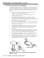
Slots and openings • If the equipment has slots or holes in the enclosure, these are
provided to prevent overheating of sensitive components inside. These openings
must never be blocked by other objects.
Lithium battery • There is a danger of explosion if battery is incorrectly
replaced. Replace it only with the same or equivalent type recommended by
the manufacturer. Dispose of used batteries according to the manufacturer’s
instructions.
Avertissement
Alimentations• Ne faire fonctionner ce matériel qu’avec la source d’alimentation
indiquée sur l’appareil. Ce matériel doit être utilisé avec une alimentation principale
comportant un fil de terre (neutre). Le troisième contact (de mise à la terre) constitue
un dispositif de sécurité : n’essayez pas de la contourner ni de la désactiver.
Déconnexion de l’alimentation• Pour mettre le matériel hors tension sans danger,
déconnectez tous les cordons d’alimentation de l’arrière de l’appareil ou du module
d’alimentation de bureau (s’il est amovible) ou encore de la prise secteur.
Protection du cordon d’alimentation • Acheminer les cordons d’alimentation de
manière à ce que personne ne risque de marcher dessus et à ce qu’ils ne soient pas
écrasés ou pincés par des objets.
Réparation-maintenance • Faire exécuter toutes les interventions de réparationmaintenance par un technicien qualifié. Aucun des éléments internes ne peut être
réparé par l’utilisateur. Afin d’éviter tout danger d’électrocution, l’utilisateur ne doit
pas essayer de procéder lui-même à ces opérations car l’ouverture ou le retrait des
couvercles risquent de l’exposer à de hautes tensions et autres dangers.
Fentes et orifices • Si le boîtier de l’appareil comporte des fentes ou des orifices, ceux-ci
servent à empêcher les composants internes sensibles de surchauffer. Ces ouvertures
ne doivent jamais être bloquées par des objets.
Lithium Batterie • Il a danger d’explosion s’ll y a remplacment incorrect de la batterie.
Remplacer uniquement avec une batterie du meme type ou d’un ype equivalent
recommande par le constructeur. Mettre au reut les batteries usagees conformement
aux instructions du fabricant.
Vorsicht
Stromquellen • Dieses Gerät sollte nur über die auf dem Produkt angegebene
Stromquelle betrieben werden. Dieses Gerät wurde für eine Verwendung mit einer
Hauptstromleitung mit einem geerdeten (neutralen) Leiter konzipiert. Der dritte
Kontakt ist für einen Erdanschluß, und stellt eine Sicherheitsfunktion dar. Diese
sollte nicht umgangen oder außer Betrieb gesetzt werden.
Stromunterbrechung • Um das Gerät auf sichere Weise vom Netz zu trennen, sollten
Sie alle Netzkabel aus der Rückseite des Gerätes, aus der externen Stomversorgung
(falls dies möglich ist) oder aus der Wandsteckdose ziehen.
Schutz des Netzkabels • Netzkabel sollten stets so verlegt werden, daß sie nicht im
Weg liegen und niemand darauf treten kann oder Objekte darauf- oder unmittelbar
dagegengestellt werden können.
Wartung • Alle Wartungsmaßnahmen sollten nur von qualifiziertem Servicepersonal
durchgeführt werden. Die internen Komponenten des Gerätes sind wartungsfrei.
Zur Vermeidung eines elektrischen Schocks versuchen Sie in keinem Fall, dieses
Gerät selbst öffnen, da beim Entfernen der Abdeckungen die Gefahr eines
elektrischen Schlags und/oder andere Gefahren bestehen.
Schlitze und Öffnungen • Wenn das Gerät Schlitze oder Löcher im Gehäuse aufweist,
dienen diese zur Vermeidung einer Überhitzung der empfindlichen Teile im
Inneren. Diese Öffnungen dürfen niemals von anderen Objekten blockiert werden.
Litium-Batterie • Explosionsgefahr, falls die Batterie nicht richtig ersetzt
wird. Ersetzen Sie verbrauchte Batterien nur durch den gleichen oder einen
vergleichbaren Batterietyp, der auch vom Hersteller empfohlen wird. Entsorgen Sie
verbrauchte Batterien bitte gemäß den Herstelleranweisungen.
Advertencia
Alimentación eléctrica • Este equipo debe conectarse únicamente a la fuente/tipo
de alimentación eléctrica indicada en el mismo. La alimentación eléctrica de este
equipo debe provenir de un sistema de distribución general con conductor neutro
a tierra. La tercera pata (puesta a tierra) es una medida de seguridad, no puentearia
ni eliminaria.
Desconexión de alimentación eléctrica • Para desconectar con seguridad la acometida
de alimentación eléctrica al equipo, desenchufar todos los cables de alimentación
en el panel trasero del equipo, o desenchufar el módulo de alimentación (si fuera
independiente), o desenchufar el cable del receptáculo de la pared.
Protección del cables de alimentación • Los cables de alimentación eléctrica se deben
instalar en lugares donde no sean pisados ni apretados por objetos que se puedan
apoyar sobre ellos.
Reparaciones/mantenimiento • Solicitar siempre los servicios técnicos de personal
calificado. En el interior no hay partes a las que el usuario deba acceder. Para evitar
riesgo de electrocución, no intentar personalmente la reparación/mantenimiento
de este equipo, ya que al abrir o extraer las tapas puede quedar expuesto a voltajes
peligrosos u otros riesgos.
Ranuras y aberturas • Si el equipo posee ranuras o orificios en su caja/alojamiento,
es para evitar el sobrecalientamiento de componentes internos sensibles. Estas
aberturas nunca se deben obstruir con otros objetos.
Batería de litio • Existe riesgo de explosión si esta batería se coloca en la posición
incorrecta. Cambiar esta batería únicamente con el mismo tipo (o su equivalente)
recomendado por el fabricante. Desachar las baterías usadas siguiendo las
instrucciones del fabricante.
安全须知 • 中文
警告
这个符号提示用户该设备用户手册中
有重要的操作和维护说明。
电源 • 该 设 备 只 能 使 用 产 品 上 标 明 的 电 源 。 设 备
必须使用有地线的供电系统供电。 第三条线
(地线)是安全设施,不能不用或跳过。
这个符号警告用户该设备机壳内有暴
拔掉电源 • 为安全地从设备拔掉电源,请拔掉所有设备后
或桌面电源的电源线,或任何接到市电系统的电源线。
露的危险电压,有触电危险。
电源线保护 • 妥善布线, 避免被踩踏,或重物挤压。
注意
阅读说明书 • 用 户 使 用 该 设 备 前 必 须 阅 读 并 理
解所有安全和使用说明。
保存说明书 • 用户应保存安全说明书以备将来使
用。
遵守警告 • 用户应遵守产品和用户指南上的所有安
全和操作说明。
维护 • 所有维修必须由认证的维修人员进行。 设备内部
没有用户可以更换的零件。为避免出现触电危险不要自
己试图打开设备盖子维修该设备。
通风孔 • 有些设备机壳上有通风槽或孔,它们是用来防止
机内敏感元件过热。 不要用任何东西挡住通风孔。
锂电池 • 不正确的更换电池会有爆炸的危险。 必须使用
与厂家推荐的相同或相近型号的电池。 按照生产厂的
建议处理废弃电池。
避免追加 • 不要使用该产品厂商没有推荐的工具或
追加设备,以避免危险。
声明
所使用电源为 A 级产品,在生活环境中,该产品可能会造成无线电干扰。在这种情况下,可能需要用
户对其干扰采取切实可行的措施。
FCC Class A Notice
This equipment has been tested and found to comply with the limits for a Class A digital device,
pursuant to part 15 of the FCC Rules. Operation is subject to the following two conditions: (1) this
device may not cause harmful interference, and (2) this device must accept any interference received,
including interference that may cause undesired operation. The Class A limits are designed to
provide reasonable protection against harmful interference when the equipment is operated in
a commercial environment. This equipment generates, uses, and can radiate radio frequency
energy and, if not installed and used in accordance with the instruction manual, may cause harmful
interference to radio communications. Operation of this equipment in a residential area is likely to
cause harmful interference, in which case the user will be required to correct the interference at his
own expense.
N
This unit was tested with shielded cables on the peripheral devices. Shielded cables must be used
with the unit to ensure compliance with FCC emissions limits.
This page has been intentionally left blank.
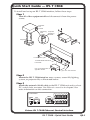
Quick Start Guide — IPL T CR48
To install and set up an IPL T CR48 interface, follow these steps:
Step 1
Turn all of the equipment off and disconnect it from the power
source.
R
IPL T S2
2
1
TX
4
COM
2
RX
RTS
Projector
Lift
Control
CTS
100
LINK
ACT
Mounting
Bolt
Projector
Mounting
Bracket
IPL
T
CR
48
R
INP
UT
1
3
R
IPL T S2
Projector
2
1
RE
1
3
2
TX
LA
Y
5
4
COM
2
4
RX
RTS
7
2
4
CTS
6
8
100
LINK
ACT
IPL
10
0
LIN
K
AC
T
T CR
48
R
INP
1
UT
3
1
REL
3
2
AY
5
4
7
2
4
6
8
100
LIN
K
ACT
IPL
T CR
48
R
INP
1
UT
3
1U Rack Shelf
1
REL
AY
3
2
5
4
7
2
4
100
LIN
K
ACT
6
8
1/4 Rack Width False Front
Face Plate
IPL
T CR
48
R
INP
1
Use 2 mounting holes on
opposite corners.
UT
3
1
REL
3
2
AY
5
4
7
2
4
6
8
100
LIN
K
ACT
(2) 4-40 x 3/16" Screws
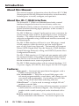
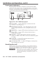
Step 2
Mount the IPL T CR48 interface near a screen, screen lift, lighting
system, or projector lift, as illustrated below.
Step 3
Attach the network (LAN) cable to the IPL T CR48 unit and to a host
PC, switch, hub, or router. See Ethernet connection in chapter 3 for
more information on this connection.
00-05-A6-00-00-01
POWER
12V
0.5A
LAN
1
2
3
4
INPUT
RELAY
1 2 3 4
5
6
7
8
Extron IPL T CR48 Ethernet Control Interface
IPL T CR48 • Quick Start Guide
QS-1
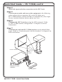
Quick Start Guide — IPL T CR48, cont’d
Step 4
Attach the input and relay connections to the IPL T unit.
Step 5
Connect power cords and turn on the equipment in the following
order: output devices (projector lift, screen lift, lights, etc.),
IPL T CR48 interface, serial controller or computer (PC), then input
devices (motion detector, alarms, photo eyes, etc.).
Step 6
Configure the IPL T interface using the ARP command. Refer
to “IPL T CR48 interface configuration” in chapter 3 for more
information.
Step 7
Communicate with the IPL T CR48 interface via the default Web
pages. Refer to “Communication with the interface” in chapter 4 for
more information.
Screen Control
Projector
Lift
Control
Projector
4
3
2
1
8
7
6
UT
INP
1
2
3
5
4
N
LA
R
WE
PO
V
12
0.5A
Extron
IPL T CR48
Ethernet Control
Interface
Lighting System
QS-2 IPL T CR48 • Quick Start Guide
Table of Contents
Chapter One • Introduction..................................................... 1-2
About this Manual..................................................................... 1-2
About the IPL T CR48 Interface.............................................. 1-2
Features......................................................................................... 1-2
Chapter Two • Installation and Operation. .................. 2-2
Installation Overview. .............................................................. 2-2
Mounting the IPL T CR48......................................................... 2-2
Rack mounting........................................................................ 2-2
Furniture or projector mounting........................................... 2-4
Rear Panel Features and Cabling. ......................................... 2-5
Ethernet/LAN.......................................................................... 2-6
Connections............................................................................. 2-6
Identification........................................................................... 2-6
Operation...................................................................................... 2-7
Front panel indicators............................................................. 2-8
Resetting the unit................................................................... 2-8
Chapter Three • Connection and Configuration. ..... 3-2
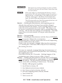
Connecting the Hardware....................................................... 3-2
Ethernet connection............................................................... 3-2
Contact closure input and relay connections........................ 3-2
Contact closure input connections.........................................3-2
Relay connections....................................................................3-3
Configuring the Hardware...................................................... 3-4
PC configuration..................................................................... 3-4
IPL T CR48 interface configuration........................................ 3-4
Configuring the IPL T CR48 using the ARP command.......... 3-5
Configuring the IPL T CR48 using direct PC connection........3-7
Firmware upgrades.................................................................3-8
Chapter Four • Communication and Control.............. 4-2
Ports Overview. .......................................................................... 4-2
Contact closure input ports.................................................... 4-2
Relay ports.............................................................................. 4-2
Communication with the Interface...................................... 4-3
Web server.............................................................................. 4-3
Accessing and using the Web server.....................................4-3
Logon and system status.....................................................4-3
Establishing or changing system or port settings................4-4
Setting and changing your passwords..................................4-5
Editing and adding e-mail alerts............................................4-6
IPL T CR48 • Table of Contents
i
Table of Contents, cont’d
Sending an e-mail alert through Telnet.............................4-7
Upgrading the firmware.........................................................4-8
Managing files.........................................................................4-8
Programmer’s Guide for the Telnet and Web Browser.4-10
Using the command/response table....................................4-10
Symbol definitions................................................................4-11
Copyright information..........................................................4-13
Password information...........................................................4-14
Error responses......................................................................4-14
References to errors (at command descriptions on the following pages)........................................................................4-14
Device Control........................................................................... 4-24
Custom Web pages............................................................... 4-24
Telnet (port 23)...................................................................... 4-24
Accessing and using Telnet...................................................4-24
Troubleshooting........................................................................ 4-25
Power connections................................................................ 4-25
Data connections.................................................................. 4-26
Configuration........................................................................ 4-26
Appendix A
Specifications, Part Numbers, Accessories........................A-2
Part Numbers and Accessories...............................................A-4
Included parts.........................................................................A-4
Accessories..............................................................................A-4
Appendix B • Glossary................................................................ B-2
Glossary......................................................................................... B-2
All trademarks mentioned in this manual are the properties of their respective owners.
68-738-05 B
11 08
ii
IPL T CR48 • Table of Contents
IPL T CR48
1
Chapter One
Introduction
About this Manual
About the IPL T CR48 Interface
Features
Introduction
About this Manual
This manual contains information about the Extron IPL T CR48
(Extron part #60-544-05) Ethernet-based relay control interface,
including how to install, configure, and operate it.
About the IPL T CR48 Interface
The Extron IPL T CR48 is an Ethernet-based relay control
interface designed to be used as one of many nodes in a
distributed control system environment, or as a stand-alone
control interface allowing legacy products to link to today’s
IP-based networks.
The IPL T CR48 has a single, 5-pole captive screw connector for
contact closure input and two, 8-pole captive screw connectors
for relays. The contact closure input and relay ports are fully
software configurable using a Web-based interface connected via
an Ethernet port.
The IPL T CR48 interface will host its own Web pages, stored
in flash memory within the device, and can accept power
over a LAN (Local Area Network). The interface will support
Telnet, SMTP (Simple Mail Transfer Protocol), ICMP (Internet
Control Message Protocol) or Ping, and DHCP (Dynamic Host
Configuration Protocol).
The IPL T CR48 interface is 1U high and one quarter rack wide.
It is rack-mountable, using either a VersaTools™ Rack Shelf Kit
(#60-190-20) or a Universal 1U Rack Shelf (#60-190-01). It can
also be mounted near a screen or projector lift.
The IPL T CR48 interface ships with an external, desktop, 12 V,
1 A power supply (#70-055-01), that accepts 100-240 VAC input.
Features
High speed — Constant high speed data throughput, with a
6 Mbit/second transfer rate.
User customizable — Tailor the on-board Web pages with
advanced programmability, e-mail alerts, and storage to suit
your needs and requirements. Or, develop your own Web
pages using off-the-shelf Web authoring software.
GlobalViewer® — Can be used to manage multiple IP Link®
products over the Web.
Direct port access — Use existing software programs to control
a device that has no Ethernet support. Any existing Extron
product with a serial control port can be interfaced with a
LAN.
Built-in multi-level security — User controls the access to
devices attached to the interface. Two levels of password
1-2
IPL T CR48 • Introduction
protection provide appropriate security.
Contact closure input ports — Can be used to sense when a
switch or relay has been activated.
Easily connected — Provides RJ-45 auto-sense 10/100 Mbs
Ethernet LAN connection.
Easily configured and controlled —
•
Using a standard Web browser (Microsoft® Internet
Explorer® V5.5, Netscape® Navigator V6.0 or higher) and
Web-based interface.
•
Using a standard Telnet client application.
•
Requires no centralized processor to operate within a
system.
Choice of mounting options — Can be mounted near a screen
or projector lift or on a rack shelf.
Remote management — The IPL T CR48 allows you to remotely
activate and deactivate projector lifts, screens, and lighting
systems.
Multiple protocols supported — The IPL T CR48 supports
Telnet, SMTP, ICMP, ARP, and DHCP.
IPL T CR48 • Introduction
1-3
Introduction, cont’d
1-4
IPL T CR48 • Introduction
IPL T CR48
2
Chapter Two
Installation and Operation
Installation Overview
Mounting the IPL T CR48
Rear Panel Features and Cabling
Operation
Installation and Operation
Installation Overview
To install and set up an IPL T CR48 relay control interface,
follow these steps:
1.
Turn all of the equipment off. Make sure that the input
devices (motion detectors, alarms, photo eyes, etc.), the
IPL unit, the output devices (projector or screen lifts, etc.)
and the serial controller are all turned off and disconnected
from the power source.
2.
Mount the IPL T CR48 unit. See “Mounting the IPL T
CR48” below.
3.
Attach the cables. See “Connecting the Hardware” in
chapter 3.
4.
Connect power cords and turn on the devices in the
following order: output devices (projector lifts, screen
lifts, lighting system, etc.), IPL T unit, serial controller or
computer (PC), then input devices (DSS, cable boxes, etc.).
5.
Configure the IPL T CR48 through Telnet, then access the
unit using an Internet browser.
Mounting the IPL T CR48
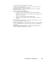
Rack mounting
For optional rack mounting, mount the unit on a VersaTools 19”
1U Rack Shelf (Extron part #60-190-20) (figure 2-1) or a standard
Universal 1U Rack Shelf (Extron part #60-190-01) (figure 2-2).
On the standard rack shelf, the unit mounts in one of four
locations to the rear of the rack or in one of four locations to the
front of the rack.
2-2
1.
If feet were previously installed on the bottom of the
IPL T CR48 unit, remove them.
2.
Mount the unit on the rack shelf, using two
4-40 x 3/16” screws in opposite (diagonal) corners to
secure the interface to the shelf.
3.
Install blank panel(s) or other unit(s) to the rack shelf.
4.
Insert the shelf into the rack, aligning the holes in the shelf
with those in the rack.
5.
Secure the shelf to the rack using the supplied machine
screws.
IPL T CR48 • Installation and Operation
IPL
T CR
48
R
INP
UT
1
3
RE
1
3
2
LA
Y
5
4
7
2
4
6
8
10
0
LIN
K
AC
T
IPL
T CR
48
R
INP
UT
1
3
1U Rack Shelf
1
RE
3
2
LA
Y
5
4
7
2
4
10
0
LIN
K
AC
T
6
8
1/4 Rack Width False Front
Face Plate
IPL
T CR
48
R
INP
UT
1
3
1
Use 2 mounting holes on
opposite corners.
RE
3
2
LA
Y
5
4
7
2
4
6
8
10
0
LIN
K
AC
T
(2) 4-40 x 3/16" Screws
Figure 2-1 — Mounting the interface on the
VersaTools shelf
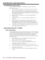
N
IPL
T
Only products in the IP Link® or VersaTools™ lines
can be mounted to a VersaTools shelf. Any 1U rackmountable Extron product can be mounted on the
standard shelf (Extron part #60-190-01).
CR
48
R
INPU
1
T
3
1
RE
3
2
LA
Y
5
4
7
2
4
6
8
10
0
LINK
AC
T
IPL
T
CR
48
R
INPU
1
T
3
1
RE
3
2
LA
Y
5
4
7
2
4
6
8
10
0
LINK
AC
T
MD
DIST
AS
RIBU
TIO
ER
N AM
IES
PL
IFIER
Figure 2-2 — Mounting the interface on the
standard shelf
IPL T CR48 • Installation and Operation
2-3
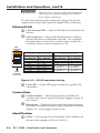
Installation and Operation, cont’d
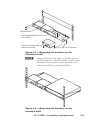
Furniture or projector mounting
In addition to using the IPL T CR48 unit on a rack, it can also be
furniture or projector mounted. Furniture mount or projector
mount the interface using the optional mounting kit (Extron part
#70-212-01, furniture, or Extron part #70-217-01, projector) as
follows:
1.
Attach the mounting brackets to the interface with the
machine screws provided (figure 2-3).
2.
If feet were previously installed on the bottom of the
interface, remove them.
3.
For furniture mounting, hold the interface with the
attached brackets against the underside of the table or
other furniture. Mark the location of the screw holes of the
bracket on the mounting surface.
4.
For furniture mounting, drill 3/32” (2 mm) diameter pilot
holes, 1/4” (6.3 mm) deep in the mounting surface at the
marked screw locations.
5.
For furniture mounting, insert #8 wood screws into the
four pilot holes. Tighten each screw into the mounting
surface until just less than 1/4” of the screw head
protrudes.
6.
For furniture mounting, align the mounting screws with
the slots in the brackets and place the interface against the
surface, with the screws through the bracket slots.
7.
For furniture mounting, slide the unit slightly forward or
back, then tighten all four screws to secure it in place.
8.
For projector mounting, secure the interface to a projector
mount or other surface by inserting the mounting bolt
through the bracket’s slotted hole.
R
IPL T S2
2
1
TX
4
RTS
COM
2
RX
Projector
Lift
Control
IPL
T CR
48
CTS
100
LINK
ACT
R
INPU
1
1
LA
Y
5
4
7
2
4
6
8
10
0
LIN
K
AC
T
Furniture Mount
R
2
1
TX
4
COM
2
RX
RTS
RE
3
2
IPL T S2
Projector
T
3
Mounting
Bolt
CTS
100
LINK
ACT
Projector Mount
Projector
Mounting
Bracket
Figure 2-3 — Furniture and projector mounting for
the IPL T CR48
2-4
IPL T CR48 • Installation and Operation
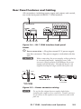
Rear Panel Features and Cabling
All connections, including power, input and output, and control,
are on the back panel of the IPL T CR48 interface.
7
00-05-A6-00-00-01
POWER
3
3
4
RELAY
1 2 3 4
2
2
INPUT
LAN
12V
0.5A
1
1
4
5
6
5
7
8
6
Figure 2-4 — IPL T CR48 interface back panel
Power
a Power connection — Plug the external 12 V power supply
into this connector. The power supply is included with the
unit.
C
When connecting the power supply, voltage polarity
is extremely important. Applying power with
incorrect voltage polarity could damage the power
supply and the interface. Identify the power cord
negative lead by the ridges on the side of the cord.
Ridges
Smooth
A
A
SECTION A–A
Power Supply
Output Cord
3/16”
(5 mm) Max.
Figure 2-5 — Power connector wiring
N
Do not tin the stripped power supply leads before
installing the captive screw connector. Tinned wires are
not as secure in the captive screw connectors and could
pull out.
IPL T CR48 • Installation and Operation
2-5
Installation and Operation, cont’d
W
The two power cord wires must be kept separate
while the power supply is plugged in. Remove
power before continuing.
To verify the polarity before connection, plug in the power
supply with no load and check the output with a voltmeter.
Ethernet/LAN
Activity LED — Yellow LED blinks to indicate LAN
b LAN
activity.
LAN connector — Plug an RJ-45 jack into this socket to
c connect
the unit to a computer network. Use a straight-
through cable to connect to a switch, hub, or router, or a
crossover cable to connect directly to a PC.
Pins:
12345678
Straight-through Cable
Crossover Cable
(for connection to a switch, hub, or router)
End 1
Insert
Twisted
Pair Wires
Pin
1
2
3
4
5
6
7
8
Wire Color
white-orange
orange
white-green
blue
white-blue
green
white-brown
brown
(for direct connection to a PC)
End 2
Pin
1
2
3
4
5
6
7
8
Wire Color
white-orange
orange
white-green
blue
white-blue
green
white-brown
brown
End 1
Pin
1
2
3
4
5
6
7
8
Wire Color
white-orange
orange
white-green
blue
white-blue
green
white-brown
brown
End 2
Pin
1
2
3
4
5
6
7
8
Wire Color
white-green
green
white-orange
blue
white-blue
orange
white-brown
brown
Figure 2-6 — RJ-45 connector wiring
LED — Green LED lights to indicate a good LAN
d Link
connection.
Connections
closure — Four inputs permit connection of
e Contact
switches and sensors to provide input (trigger events) to
the system.
ports — Eight relay ports provide contact closure
f Relay
activation of relays for power, screen projector lift control,
drapes, etc., when trigger events occur.
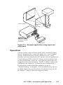
Identification
UID # — The unique User ID Number (MAC address) of
g the
unit (for example, 00-05-A6-00-00-01).
2-6
IPL T CR48 • Installation and Operation
Screen Control
Projector
Lift
Control
Projector
4
3
2
1
8
7
6
UT
INP
1
2
3
5
4
N
LA
R
WE
PO
V
12
0.5A
Extron
IPL T CR48
Ethernet Control
Interface
Lighting System
Figure 2-7— Example application using input and
relay ports
Operation
Connect power cords and turn on the relay controlled output
devices (projector lifts, screen lifts, lights, etc.), input (trigger)
devices (motion detectors, alarms, photo eyes, etc.), relay
interface, and network devices (PC, laptop, network equipment).
Check indicator LEDs on the PC/laptop, on the interface, and
on the network hub/router, etc., to ensure that all devices are
plugged in and communicating. The IPL T CR48 is ready to be
configured (see chapter 3, “Connection and Configuration”).
If connection or communication problems occur, see
“Troubleshooting” in chapter 4. If the troubleshooting tips do
not help, check with your local network administrator, or call
the Extron S3 Sales & Technical Support Hotline.
IPL T CR48 • Installation and Operation
2-7
Installation and Operation, cont’d
Front panel indicators
The front panel of the IPL T CR48 has several indicator LEDs
which show the current status of communications to and from
the unit. A reset button is also available from the front panel, in
a small recess next to the Power LED (a).
IPL T CR48
INPUT
1
3
RELAY
1
3
5
7
R
100
5
LINK
6
ACT
2
1
4
3
2
2
4
6
8
7
4
Figure 2-8— IPL T CR48 front panel
Power LED — A green LED lights to indicate that the
a interface
is receiving power.
button (recessed) — See “Resetting the unit” later
b Reset
in this chapter for details on this multiple function reset
button.
c Input LEDs — A green LED indicates that the port is active.
LEDs — A green LED indicates that the relay is
d Relay
closed and activated.
LED — A green LED indicates that the connection
e 100
speed is 100 Mbs. If the LED is not lit, the connection speed
is 10 Mbs.
LED — A green LED indicates that the unit is
f Link
connected to an active network.
(Activity) LED — A yellow LED lights to indicate that
g Act
data is being sent/received.
Resetting the unit
There are five reset modes available by using the Reset button
(b) on the front panel. The Reset button is recessed, so use of a
pointed stylus, ballpoint pen, or Extron Tweeker is suggested.
C
2-8
Review the reset modes carefully. Use of the wrong
reset mode may result in unintended loss of flash
memory programming, reassignment of ports, or a
unit reboot.
IPL T CR48 • Installation and Operation
C
N
The listed reset modes (with the exception of Mode
2) will close all open IP and Telnet connections and
close all sockets.
If the reset button is continuously held down, every 3
seconds the LED will pulse (blink) and put the unit in a
different mode, corresponding to the underscored notes
in Modes 3 through 5. The Mode 5 LED blinks three
times, the third blink indicating that it’s the last mode.
The following modes are listed as separate functions, not
a continuation from Mode 1 to Mode 5.
Mode 1 — Holding the Reset button while applying power
defaults the unit back to the base firmware that shipped
with the unit from the factory. Event scripting does not start
when the unit is powered on in this mode. This allows you
to recover a unit that has incorrect code or updated firmware
running. All user files and settings are maintained. User Web
pages may not work correctly if using an earlier firmware
version.
Mode 2 — Not applicable.
Mode 3 — Holding the Reset button until the Power LED blinks
once (3 seconds) followed by a momentary
(<1 second) press will turn events either on or off, depending
on the current state of the events:
If the events are currently stopped following the momentary
(<1 second) press, the Power LED will flash twice indicating
the starting of events.
or
If events are currently running following the momentary (<1
second) press, the Power LED will flash three times indicating
the stopping of events.
Each flash will last for .25 seconds. Nothing happens if the
momentary press does not occur within 1 second.
Mode 4 — Holding the Reset button until the Power LED blinks
twice (6 seconds) followed by a momentary (<1 second) press
resets IP settings. The Power LED will blink four times in
quick succession, confirming a Mode 4 reset. This mode
1. Enables ARP program capability
2. Sets IP back to factory IP
3. Sets Subnet back to factory default
4. Sets Gateway back to factory default
5. Sets port mapping back to factory default
6. Turns DHCP off
7. Turns events off
IPL T CR48 • Installation and Operation
2-9
Installation and Operation, cont’d
Nothing happens if the momentary press does not occur
within one second.
Mode 5 — Holding the Reset button until the Power LED blinks
three times (9 seconds) followed by a momentary
(<1 second) press causes an absolute system reset back
to factory default conditions. Nothing happens if the
momentary press does not occur within 1 second. The power
LED will blink four times in quick succession, confirming a Mode
5 reset.
2-10 IPL T CR48 • Installation and Operation
IPL T CR48
3
Chapter Three
Connection and Configuration
Connecting the Hardware
Configuring the Hardware
Connection and Configuration
Connecting the Hardware
To connect the IPL T CR48 unit, connect the input and output
devices to the unit using figure 3-1 as a guide.
Cables to Relay Controlled Devices
(projector/screen lift, lights, etc.)
4
3
2
1
8
7
6
T
INPU
1
2
3
5
Cables from Triggering Devices
(sensors, counters, switches, etc.)
4
N
LA
WER
PO
V
12
A
0.5
Extron
IPL T CR48
Ethernet Relay
Control Interface
Crossover
Cable
or
PC
Straightthrough
Cable
Straightthrough
Cable
LAN
Straightthrough
Cable
Fake
Hub
Hub/Switch/Router
or
Straightthrough
Cable
PC
TCP/IP
Network
Ethernet
PC
Figure 3-1 — IPL T CR48 connections
Ethernet connection
This type of connection is used on an ongoing basis to connect
the IPL T CR48 and to control switching and display devices
through the unit.
1.
Plug one end of a Cat 5, straight-through Ethernet cable
into the rear panel Ethernet connector on the IPL T CR48.
Refer to figure 2-6 for RJ-45 connector wiring.
2.
Plug the other end of the Ethernet cable into a network
switch, hub, or router connected to an Ethernet LAN or to
the Internet.
3.
Launch your Web browser on your PC and type in the
Web address that you set up on the IPL T CR48 interface
(refer to “IPL T CR48 interface configuration” later in this
chapter). The IPL T CR48 default Web page should be
displayed.
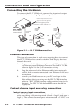
Contact closure input and relay connections
Contact closure input connections
The IPL T CR48 relay control interface can be connected to any
relay providing a closure to ground (closed = logic 1 and open =
logic 0). The contact closure inputs are connected to 5 VDC via a
3-2
IPL T CR48 • Connection and Configuration
1 kohm pull-up resistor and must be wired with a ground. This
allows the input to be tied to devices such as motion detectors,
alarms, photo eyes, etc. Users define what this input triggers via
control software.
1.
Connect one end of the input cable to a 3.5 mm, 5-pole
captive screw connector, wired appropriately, and plug
it into the rear panel input port connector of the interface
unit.
2.
Connect the other end of the input cable to the input relay
device which will provide a triggering signal.
Screen Control
Projector
Lift
Control
Projector
4
3
2
1
8
7
6
UT
INP
1
2
3
5
4
N
LA
R
WE
PO
V
12
0.5A
Extron
IPL T CR48
Ethernet Control
Interface
Lighting System
Figure 3-2 — Typical IPL T CR48 relay control
interface operating configuration
Relay connections
The IPL T CR48 relay control interface can be connected to any
device that can be activated by a relay closure. This allows the
relay to be tied to devices such as lights (preset recall), projector
lifts, screen or drape controllers, etc. Users define what triggers
this action via control software.
IPL T CR48 • Connection and Configuration
3-3
Connection and Configuration, cont’d
1.
Connect one end of the relay cable to a 8-pole captive
screw connector, wired appropriately, and plug it into the
rear panel relay port connector of the interface unit.
2.
Connect the other end of the relay cable to the device
which will be activated when the triggering signal is
received.
Configuring the Hardware
To function together properly, both the controlling PC and
the IPL T CR48 must be configured correctly. The PC must be
network-capable, with the proper protocols installed and the
hardware configured correctly. The IPL T CR48 must be set to
recognize and accept commands and pass them through to the
projector lift, screen lift or other controlled device.
PC configuration
This manual assumes that you have a Windows® PC equipped
with an operating network adapter. To allow your PC to work
with Extron’s Ethernet-controlled products, the TCP/IP protocol
must be installed and properly configured.
For use on an existing Ethernet LAN intranet, your network
administrator can provide you with a unique IP address or
confirm whether you need to set up the IPL T CR48 unit for
DHCP (Dynamic Host Configuration protocol) to have an
address assigned automatically when you sign on.
IPL T CR48 interface configuration
When you power on the IPL T CR48 unit for the first time, there
are two ways to set up the IP address:
1. Use the ARP command method.
2. Use the direct PC method.
The default Web pages that are pre-loaded on the IPL T CR48
provide a way to reconfigure the IPL T unit once it has an
active network connection with IP access. These Web pages
are compatible with Netscape® Navigator (version 6.0 or
higher), or Microsoft® Internet Explorer (version 5.5 or higher).
See “Communication with the Interface” in chapter 4 for
information on accessing and configuring the interface.
Once the unit has been reconfigured, an Ethernet (intranet or
Internet) connection can subsequently be used to contact or
control it. Refer to “Ethernet connection” earlier in this chapter
for additional information.
3-4
IPL T CR48 • Connection and Configuration
Configuring the IPL T CR48 using the ARP
command
You can make use of the ARP (Address Resolution Protocol)
command to set up an IP address for your IPL T CR48 interface.
The ARP command tells your computer to associate the
IPL T CR48 unit’s MAC address with the assigned IP address.
You must then use Ping to access the IPL T CR48 unit, at which
point the device server’s IP address will be reconfigured.
N
In order to use this setup method, both your computer
and IPL T CR48 interface must be connected to the same
LAN. Or, you may use a crossover Ethernet cable to
connect the device server directly to your computer’s
Ethernet card.
Use ARP to configure the IP address as follows:
1. Obtain a valid IP address for your IPL T CR48 from your
network administrator.
2. Obtain the IPL T CR48 unit’s MAC address (UID #) from
the label on its back panel.
3. If the unit has never been configured and is still set for
factory defaults, go to step 4. If not, perform a Mode 4
system reset. For detailed information on reset modes, see
“Resetting the unit” in chapter 2.
C
Your IPL T CR48 unit must be configured with the
factory default IP address — 192.168.254.254 —
before executing the ARP command, as described
below.
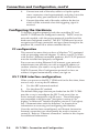
4. Access the MS-DOS command prompt, then execute the
‘arp –s’ command.
Enter the desired new IP address and the MAC address
(the MAC address is located on the rear panel’s upper left
corner) for the IPL unit. For example:
arp –s 10.13.170.15 00-05-A6-00-0A-90
IPL T CR48 • Connection and Configuration
3-5
Connection and Configuration, cont’d
Figure 3-3 — Executing the ARP command
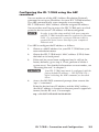
5. Execute a Ping command by typing your new IP address at
the command prompt. For example:
ping 10.13.170.15
After issuing this command, the unit will change to the
new address and start responding to the Ping requests, as
shown below. The IPL unit’s IP address should now be
updated to the new address, and then you can reconnect
using either Telnet or the Web to verify that the update was
successful.
3-6
Figure 3-4 — Unit response to a Ping request
6.
After verifying that the change was successful, issue the
arp –d command at the DOS prompt. For example:
arp –d 10.13.170.15 will remove 10.13.170.15 from the arp
table
or
arp –d* to remove all static IP addresses from the arp table.
IPL T CR48 • Connection and Configuration
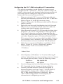
Configuring the IPL T CR48 using direct PC connection
This type of connection is used initially to connect to and
configure the IPL T CR48 unit. The unit’s default settings (IP
address, subnet mask, and (optional) administrator name and
password) must be changed in order to use the unit on an
intranet (LAN) or on the Internet (WAN).
1.
Plug one end of a CAT 5, crossover Ethernet cable into
the rear panel Ethernet connector on the IPL T CR48 unit.
Refer to figure 2-6 for RJ-45 connector wiring.
2.
Plug the other end of the Ethernet cable into the Ethernet
port on your PC.
3.
Right click the Network Neighborhood or My Network
Places icon on your Windows (98, 2000, NT®, ME, XP)
desktop and select Properties from the menu.
4.
Select Internet Protocol (TCP/IP) from the list then select
Properties. (If you are using Windows 2000, right-click
Local Area Connection and select Properties from the
menu, then select Internet Protocol (TCP/IP) from the list
and select Properties again.) If Internet Protocol (TCP/
IP) is not on the list, it must be added (installed). Refer to
your Windows user’s manual or the online Help system
for information on how to install the TCP/IP protocol.
5.
Write down your current IP address and Subnet Mask
below. If your PC is set to “Obtain an IP address
automatically,” make a note of that, instead.
IP Address:
.
Subnet Mask:
6.
.
.
.
.
.
Click “Specify an IP address” or “Use the following IP
address” (depending on your operating system), and leave
the default gateway blank. Enter the following values:
IP address: 192.168.254.253
Subnet mask:
255.255.0.0
7.
Save the changes and exit the Network setup. Reboot the
PC, if required, for the changes to become effective.
8.
Launch your Web browser (Netscape Navigator or
Internet Explorer), and type “http://192.168.254.254/
index.html” in the browser’s Address field. The
IPL T CR48 default Web page is displayed. Refer to
“IPL T CR48 configuration,” in this chapter, for
information on configuring your unit.
IPL T CR48 • Connection and Configuration
3-7
Connection and Configuration, cont’d
9.
After configuring your IPL T CR48, repeat steps 3 and 4
and change your TCP/IP settings back to their original
configuration.
Firmware upgrades
Firmware upgrades become available as improvements are
made to the versatility and functionality of the IPL T CR48.
These upgrades will be available for download from the Extron
Web site. For information on upgrading the firmware, see
“Upgrading the firmware” in chapter 4.
3-8
IPL T CR48 • Connection and Configuration
IPL T CR48
4
Chapter Four
Communication and Control
Ports Overview
Communication with the Interface
Programmer’s Guide for the Telnet and Web Browser
Device Control
Troubleshooting
Communication and Control
Ports Overview
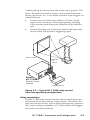
Contact closure input ports
The contact closure inputs on the IPL T CR48 are able to detect
a closed circuit between any of the inputs and ground. The
contact closure input ports utilize a 1 kohm pull-up resistor in a
TTL (5VDC) circuit to sense external switch or contact closure.
By connecting one side of an external switch or relay to the
contact closure ground port and the other side to one of the four
contact closure input ports, logic 1 (closed) can be produced.
Logic 0 (open) can be produced by disconnecting either side of
the external switch or relay from the IPL T CR48.
+5V
1K
Figure 4-1 — Equivalent circuit for control
closure input
Relay ports
The relay ports can be used for remote switching of low level
signals. The relays can be activated via software in three ways,
through
1.
the Port Settings default Web page found under the
Configuration tab (see figure 4-5)
2.
Telnet
3.
an event script running on the IPL T CR48
The Port Settings Web page allows the user to turn any of the
eight relays “on” or “off.”
Telnet allows the user to send SIS commands (Refer to the
“Command/response table” later in this chapter) to turn the
relays “on” or “off” directly.
Event scripting allows an event script to turn the relays “on” or
“off” based on the state of the four inputs on the IPL T CR48, or
any other event script conditions.
States of the relay ports are volatile; if a given relay port is “on”
and the unit’s power is turned off, the state of the port is not
remembered. When the unit is powered on, the relay ports are
open and the corresponding LED will be “off.”
4-2
IPL T CR48 • Communication and Control
Communication with the Interface
Web server
The on-board Web server is displayed as a set of default Web
pages which can be accessed via a Web browser. These pages are
the primary means of communication with, and control through,
the IPL T CR48 interface. Web browsers such as Netscape®
Navigator (version 6.0 or higher), or Microsoft® Internet
Explorer (version 5.5 or higher) can be used, but if using Internet
Explorer, you must also have Microsoft Script (version 5.6 or
higher).
The PC used to access the Web server must have a connection
in common with the IPL T CR48 interface. In other words, both
the unit and the PC should be connected to your local intranet
or Internet.
If you have established passwords for the interface, you will be
shown a Password window when your browser accesses the IPL
T CR48 unit (but not when you initially access the Web server,
since no passwords have been established). Your level of control
over the interface depends on the password you enter in this
password screen. If you enter the administrator’s password, you
will have control of all matters of configuration. If you enter a
user password, you will be restricted to control of only contact
closure and relay setting devices, and/or view status.
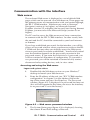
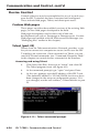
Accessing and using the Web server
Logon and system status
1. Double-click the Web browser icon on your Windows®
desktop to launch your Web browser.
2.
Enter the IP address of the unit (see “IPL T CR48 interface
configuration” in chapter 3) in the Address field at the
top of the screen and press the Enter key. The Password
window (figure 4-2) is displayed if a password has been set
(this will not happen the first time you access the interface,
as no password is set at the factory).
Figure 4-2 — Web server password window
3.
The System Status page (figure 4-3) is displayed, showing
the current IP and Port settings of the unit.
IPL T CR48 • Communication and Control
4-3
Communication and Control, cont’d
Figure 4-3 — Web server system status screen
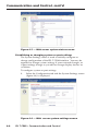
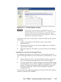
Establishing or changing system or port settings
The System Settings screen is used to initially configure or
change configuration of the IPL T CR48 interface. You may be
required to change system settings if your network changes, or
if port settings change as you add or change display devices or
switchers.
To configure system or port settings:
1.
Select the Configuration tab and the System Settings screen
(figure 4-4) is displayed.
Figure 4-4 — Web server system settings screen
4-4
IPL T CR48 • Communication and Control
2.
Make changes to the IP settings or Date/Time settings, as
necessary.
3.
Click the Submit button to enter the changes, or click the
Cancel button to revert to the previous settings.
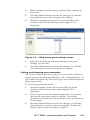
4.
Click Port Settings on the menu (on the left side of the
window) and the Port Settings screen (figure 4-5) is
displayed.
Figure 4-5 — Web server port settings screen
5.
Select the desired port and make changes to the port
settings, as necessary.
6.
Click the Submit button to enter the changes, or click the
Cancel button to revert to the previous settings.
Setting and changing your passwords
For security reasons you may want to set passwords initially, or
change passwords either periodically or on a scheduled basis. If
passwords have been set, you must log on as an administrator to
change passwords.
To set or change the passwords:
1.
Click Passwords on the menu (on the left side of the
window) and the Passwords screen (figure 4-5) is
displayed.
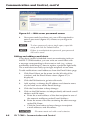
2. Enter the passwords for administrator and/or user, then
re-enter the same passwords to confirm. Passwords
should have a minimum of 4 characters and a maximum of
12 characters.
3.
Click the Submit button to enter the changes, or click the
Cancel button to revert to previous settings. If fields are
blank, no passwords have been assigned.
IPL T CR48 • Communication and Control
4-5
Communication and Control, cont’d
Figure 4-6 — Web server passwords screen
4.
Once passwords have been set, you will be required to
enter a password (figure 4-2) whenever you log on to
the unit.
N
To clear a password, enter a single space, repeat the
entry, and click the Submit button.
N
If there is no administrator password, your password
will not be saved.
Editing and adding e-mail alerts
If you have created scheduled events or monitoring tasks on
the IPL T CR48 interface, you can write an e-mail alert with
a message corresponding to that event or task (e.g., a timer
notification indicating it’s time to replace a projector light bulb).
The e-mail alert can notify up to eight recipients at one time.
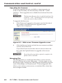
To edit notification e-mail addresses from the Email Alerts page:
1.
Click Email Alerts on the menu (on the left side of the
window) and the Email Alerts screen (figure 4-7) is
displayed.
2.
Click the Edit button to go into edit mode.
3.
Add, update, or change the IP address and domain name
of your mail server under Email Settings.
4.
Click the Save button to keep changes.
5.
Click on the Edit buttons to independently edit each e-mail
address and file name.
a. Enter the e-mail address of the alert recipient in one of
the numeric mailboxes under E-mail Address.
b. Enter the name of the file containing the alert message
under File Name.
c. Click the Save button to keep changes to recipient
e-mail addresses and file names.
C
4-6
File names must end with a .eml extension.
IPL T CR48 • Communication and Control
Figure 4-7 — Email alerts screen
N
Due to the 7 character limit for full file names, it’s
advised that you use numeric titles (e.g., 1.eml, 24.eml).
Numeric titles reduce the characters of the file name,
and assist in keeping the alert files organized. However,
alphabetical titles are permitted.
To finalize your new e-mail alerts within the Web server, do the
following:
6.
Obtain your gateway IP address from your system
administrator.
7. Click System Settings on the menu (figure 4-4) on the left
side of the window.
8.
Place the gateway IP address into the Gateway IP Address
field.
Sending an e-mail alert through Telnet
To complete the process of sending an e-mail alert, you must
send it through a Telnet session and receive confirmation. To do
so
1.
Open a Telnet session. For instructions on how to do this,
see “Accessing and using Telnet” later in this chapter.
2.
Use the “Send email” SIS command to send the alert to the
e-mail address of a numeric mailbox (see figure 4-7). Refer
to the “Command/response table for Simple Instruction
Set (SIS) commands” later in this chapter for specific
command code.
For example, the code for sending an alert from the 4th numeric
mailbox would be Esc 4 SM}
IPL T CR48 • Communication and Control
4-7
Communication and Control, cont’d
Upgrading the firmware
Firmware upgrades become available as improvements are
made to the versatility and functionality of the IPL T CR48
interface. These upgrades are available for download from the
Internet.
C
The firmware file you select to upload must have the
extension “.S19”. Uploading the incorrect file may
cause your unit to stop working.
To upgrade the firmware:
1.
Click Firmware Upgrade on the menu (on the left side of
the window) and the Firmware Upgrade screen
(figure 4-8) is displayed.
Figure 4-8 — Web server Firmware Upgrade screen
2.
Click the Browse button to find the most current available
version of the firmware.
If you find a later version than the one shown above the
box, click the Upload button to upgrade to the newer
version.
C
If you leave the page before upload is complete, the
upload will be cancelled.
Managing files
File Management is a useful tool that allows you to use and
upload existing and custom Web pages. Custom pages can be
developed using a third-party Web page development program
such as FrontPage® or Dreamweaver®. File management also
allows you to remove unnecessary or outdated files when they
are no longer needed.
4-8
IPL T CR48 • Communication and Control
To add or update files:
1.
Select the File Management tab and the File Management
screen (figure 4-9) is displayed.
Figure 4-9 — Web server File Management screen
2.
Click the Browse button to locate the file you want to
upload.
3.
Click the Upload File button to upload the file.
The file is added to the list of files under the Files column. After
ten files have been loaded, additional file management pages
appear in the page navigation area (on the right side of the
screen).
To delete unwanted files:
1.
Select the File Management tab and the File Management
screen (figure 4-9) is displayed.
2.
Find the file you wish to delete under the Files list.
3.
Click the Delete button of the file to be deleted. If you wish
to delete additional files, wait for the screen to refresh
before clicking the Delete button of the next file.
If you wish to delete all files, click the Delete All button. The file
count will revert to 0 and all subsequent pages will be deleted.
IPL T CR48 • Communication and Control
4-9
Communication and Control, cont’d
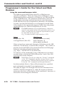
Programmer’s Guide for the Telnet and Web
Browser
Using the command/response table
The following are either Telnet (port 23) or Web browser
(port 80) commands. There are some minor differences when
implementing these commands via Telnet or via URL encoding
using a Web browser. All commands listed below will work
using either connection method, but due to some limitations
of the Web browser, the encapsulation characters are modified
to make sure that the Web browser will properly handle them.
All examples in the command/response table show the proper
implementation in a Telnet or Web browser session.
N
For Web browsers: all non-alphanumeric characters
must be represented as their hex equivalent such as %xx
where xx equals the two character representation of the
hex byte that needs to be sent
(e.g., a comma would be represented as %2C).
Telnet
Web Browser
Escape (Hex 1B)
W [must not be encoded]
Carriage Return (Hex 0D)
Pipe Character (|)
[must not be encoded]
When using these commands through a Web browser, the URL
reference is used below to shorten the examples. This would, in
practice, be the full URL of the control interface and Web page
reference including all path information
(e.g., http://192.168.100.10/myform.htm).
To send any of the commands using a Web browser you need
to prefix them with the full URL followed by ?cmd= (See URL
Encoding later in this chapter).
N
With Telnet you can use either the “Escape” commands
or the “W” commands, and the carriage return or the
pipe character. With the Web browser, you are required
to use the “W” commands and the pipe character.
In either method {Data} = Data will be directed to a specified
port and must be encoded if non-alphanumeric.
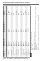
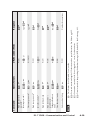
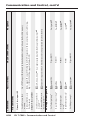
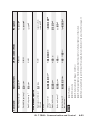
The table on pages 4-15 through 4-19 lists the commands that
the IPL T interface recognizes as valid, the responses that are
returned to the host, a description of the command’s function, or
the results of executing the command.
4-10
IPL T CR48 • Communication and Control
N
Upper and lower case text can be used interchangeably
except where noted.
Symbol definitions are shown below. An ASCII to HEX
conversion table is also provided in figure 4-10.
ASCII to HEX Conversion Table
s
Figure 4-10— ASCII-to-HEX conversion table
Symbol definitions
] = CR/LF (carriage return/line feed)
} = Carriage return (no line feed)
• = Space (hard) character
X! = Specific port number (01-99)
The port number will be represented as two ASCII characters (2
bytes) [example: port 05 would be represented as 30 35 in hex]
00 = All ports
X@ = Command data section
N
For Web encoding only - Data will be directed to a
specified port and must be encoded (URL encoding)
if non-alphanumeric. Since data can include either
command terminator, they must be encoded as follows
when used within the data section: space (hex: 20) would
be encoded as %20 and Plus sign (hex: 2B) would be
encoded as %2B.
X# = Greenwich Mean Time (GMT) offset value (-12.0 to +14.0)
X% = On/off status: 0 = off/disable; 1 = on/enable
X^ = Dirty status: 1 = RAM needs to be saved to Flash; 0 = RAM has
been saved to Flash (OK to power off/reset)
IPL T CR48 • Communication and Control
4-11
Communication and Control
X1! = Unit version number
X1@ = Name is a text string of up to 24 characters drawn from the
alphabet (A-Z), digits (0-9), and/or a minus sign/hyphen (-).
No blank or space characters are permitted as part of a name.
No distinction is made between upper and lower case. The first
character must be an alpha character. The last character can not
be a minus sign/hyphen.
X1# = Set local date and time format (MM/DD/YY-HH:MM:SS,
e.g., 06/21/02-10:54:00)
Read local date and time format (day of week, date month year
HH:MM:SS, e.g., Thu, 20 Feb 2003 18:19:33)
X1$ = IP address (xxx.xxx.xxx.xxx); leading zeros in each of four fields
are optional in setting values, and are suppressed in returned
values.
X1% = Domain name (e.g., extron.com, icia.org)
X1* = Hardware (MAC) address (xx-xx-xx-xx-xx-xx)
X1( = Subnet mask (xxx.xxx.xxx.xxx); leading zeros in each of four
fields are optional in setting values, and are suppressed in
returned values.
X2@ = Status: 0 = working; 1 = fail
X2# = Priority status for receive timeout: 0 = priority set to Send Data
String command parameters; 1 = priority set to Configure rcv
timeout command parameters.
X3# = Password: maximum length of 12 characters and no special
characters.
N
User password cannot be assigned if no administrator
password exists and returns E14. If an admin password
is cleared, then the user password is removed too.
X3$ = Daylight saving time: 0 = off/ignore; 1 = on (use in northern
hemisphere)
X3% = Event number: range = 0 - 99 (Max.)
X3^ = Event buffer: 0 = receive; 1 = user (absolute); 2 = user (relative); 3
= NVRAM
X3& = Event buffer offset: range = 0 - MaxBufferSize
X3* = Event data size: b = bit; B = byte (8 bit); S = short (16 bit);
L = long (32 bit)
N
4-12
This parameter is case sensitive.
IPL T CR48 • Communication and Control
X3( = Event data to write
X4# = Input state: 0 = off; 1 = on
X4$ = Number of bytes to read
X4% = E-mail event number: Range = 1-64 (Max)
X4^ = E-mail recipient address: Maximum number of characters for a
full e-mail address is 31 characters.
X4& = Name of e-mail file to be sent: first line of file is subject, the rest
is the body of the e-mail.
N
E-mail files must have the file extension .eml.
X4* = Event Status fields (8): event_type, event_state, event_paused,
error_status, RcvBuff_startptr, RcvBuff_endptr, UsrBuff_startptr,
UsrBuff_endptr
X4( = Default Name: Combination of model-name and last 3 pairs of
MAC address (e.g., IPL-T-CR48-00-02-3D)
X5! = Direct access: 0 = direct access not in use; 1 = direct access in use
X5@ = Connection’s security level: 0 = not logged in, 1 = user,
2 = administrator
X5# = Timeout for data pass-through mode, after which event data can
be inserted into the transmit buffer.
X5$ = ASCII digit(s) representing numeric value of data element read
from event buffer; leading zeros are suppressed.
X6# = Pulse time in 20 ms per count. If parameter is missing or = 0,
pulse length = default (25 counts = 500 ms), max (65536 counts)
X6$ = Time in seconds to keep sending the broadcast message (0-255,
default 10)
N
Zero (0) clears broadcast mode.
Copyright information
]© COPYRIGHT 2003, EXTRON ELECTRONICS IPL T CR48,
Vx.xx]
Mon, 17 Feb 2003 11:27:33]
The copyright message is displayed upon connecting to
IP Link® product via TCP/IP or Telnet. Vx.xx is the firmware
version number. The current date and time is displayed. This is
followed by a Password prompt.
IPL T CR48 • Communication and Control
4-13
Communication and Control, cont’d
Password information
The “]Password:” prompt requires a password (administrator
level or user level) followed by a carriage return. The prompt is
repeated if the correct password is not entered.
If the correct password is entered, the unit responds with
“]Login Administrator]” or “]Login User]”, depending
on the password entered. If passwords are the same for both
administrator and user, the unit will default to administrator
privileges.
Error responses
When the IPL T CR48 interface receives a valid command,
it executes the command and sends a response to the host
device. If the unit is unable to execute the command because
the command contains invalid parameters, it returns an error
response to the host.
E10 — Invalid command
E12 — Invalid port number
E13 — Invalid parameter
E14 — Not valid for this configuration
E17 — System timed out
E22 — Busy
E24 — Privilege violation
E25 — Device not present
E26 — Maximum number of connections exceeded
E27 — Invalid event number
E28 — Bad filename/file not found
References to errors (at command descriptions on the
following pages)
24
= Commands that give E24 (privilege violation) if not
administrator level
4-14
27
= Commands that may give E27 (invalid event number)
28
= Commands that may give E28 (file not found)
IPL T CR48 • Communication and Control
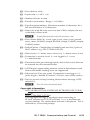
IPL T CR48 • Communication and Control
4-15
1*3*X6# O
X!*2O
X!*1O
X!*0O
X!O
ASCII (Telnet)
X!]
1Q
1Q
2Q
Query bootstrap version
X! = Specific port number (01-99)
X% = On/off status: 0 = off/disable; 1 = on/enable
X1! = Unit version number
X4# = Input state: 0 = off; 1 = on
X6# = Pulse time in 20 ms per count. If parameter is missing or = 0, pulse length = default (25 counts = 500 ms), max (65536 counts)
X1!]
X1!]
sum of responses from 2Q3Q-4Q]
X1!]
X4#]
X%]
CpnX! • Rly0]
CpnX! • Rly1]
CpnX! • Rly2]
CpnX! • Rly3]
Response
N
2Q
Q
0Q
Q
0Q
X!%D+
X!%2A3%2AX6# O
X!%2A2O
X!%2A1O
X!%2A0O
X!O
URL Encoded (Web)
Query firmware version
Query verbose version
information
Query firmware version
Firmware Version/Part Number/Information
View the input state or
value
Input Contact Closure port
View relay status
Turn relay OFF
Turn relay ON
Toggle relay
Pulse relay
Relay functions
Command
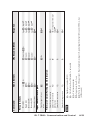
4-16
3Q
ASCII (Telnet)
3Q
URL Encoded (Web)
(plus web ver.-desc-UL
date/time)]
X1!
Response
3I
4I
3I
4I
IPL T CR48 • Communication and Control
X1! = Unit version number
X1@ = Name is a text string of up to 24 characters drawn from the alphabet (A-Z), digits (0-9), and/or a minus sign/hyphen (-).
X4( = Default Name: Combination of model-name and last 3 pairs of MAC address (e.g., IPL-T-CR48-00-02-3D)
Ipn • X4(]
N
W%20CN|
E•CN}
Set Unit name to factory
default24
Ipn • X1@]
Four contact input ports ,
Eight relay ports]
# bytes used out of #
kbytes]
# bytes used out of #
kbytes]
IPL T CR48
WX1@CN|
E X1@CN}
Set Unit name
IP Setup Commandsz
2I
2I
Request model
description
Request system memory
usage
Request user memory
usage
1I
1I
Request model number
Query updated firmware
X1! (plus web ver.-desc-UL
4Q
4Q
version
date/time)]
N An asterisk (*) placed after the version number indicates which version is currently running. A question mark (?) indicates that only the
factory firmware version is loaded. A caret (^) after the version number indicates the firmware version that should be running, but a Mode
1 reset was executed. The default factory firmware version is loaded. An exclamation point (!) after the version number indicates corrupted
firmware.
Request part number
N
N
60-544-05]
Query factory firmware
version
Command
Communication and Control, cont’d
IPL T CR48 • Communication and Control
4-17
W1DH|
W0DH|
E1DH}
E0DH}
Set DHCP off24
Idh0]
Idh1]
X3$]
X3$ = Daylight saving time: 0 = off/ignore; 1 = on (use in northern hemisphere)
= Read local date and time format
X1$ = IP address
X1# = Set local date and time format
WCX|
ECX}
IpxX3$]
X1@ = Name is a text string of up to 24 characters drawn from the alphabet (A-Z), digits (0-9), and/or a minus sign/hyphen (-).
WX3$CZ|
E X3$CX}
Set daylight savings
time24
Read daylight savings
time
Set DHCP on24
X#]
WCZ|
ECZ}
Read GMT offset
IpzX#]
X% = On/off status: 0 = off/disable; 1 = on/enable
WX#CZ|
E X#CZ}
Set GMT offset24
X1#]
WCT|
ECT}
Read time / date
Ipt • X1#
WX1#CT|
E X1#CT}
Set time / date24
X1@]
X# = Greenwich Mean Time (GMT) offset value (-12.0 to +14.0)
WCN|
ECN
Read Unit name
Response
N
URL Encoded (Web)
ASCII (Telnet)
Command
4-18
IPL T CR48 • Communication and Control
W%20CA|
E•CA}
Ipa • ]
Ipa • X3#]
X3# = Password: maximum length of 12 characters and no special characters. See Note on pg. 4-12.
WX3#CA|
E X3#CA}
X1$]
WCG|
ECG}
Read gateway IP
address24
Set administrator
password24
Clear administrator
password24
Ipg • X1$]
X1( = Subnet mask (xxx.xxx.xxx.xxx); leading zeros in each of four fields are optional in setting values, and are suppressed in returned values.
WX1$CG|
E X1$CG}
Set gateway IP address
X1(]
X1* = Hardware (MAC) address (xx-xx-xx-xx-xx-xx)
WCS|
ECS}
Read subnet mask
Ips • X1(]
WX1(CS|
E X1(CS}
X1*]
WCH|
ECH}
Read hardware address
(MAC)
Set subnet mask
X1$]
X1$ = IP address
WCI|
ECI}
Read IP address
Ipi • X1$]
X% = On/off status: 0 = off/disable; 1 = on/enable
WX1$CI|
E X1$CI}
Set IP address24
X%]
WDH|
EDH}
View DHCP mode
Response
N
URL Encoded (Web)
ASCII (Telnet)
Command
Communication and Control, cont’d
IPL T CR48 • Communication and Control
4-19
WCA|
WX3#CU|
W%20CU|
WCU|
WX%CV|
WCV|
WCK|
WX6$EB|
WEB|
WCC|
ECA}
E X3#CU}
E
ECU}
E X%CV}
ECV}
ECK}
E X6$EB}
EEB}
ECC}
Read administrator
password24
Set user password24
Clear user password24
Read user password24
Set verbose mode24
Read verbose mode
Read connection’s
security level
Configure Broadcast
mode
View Broadcast mode
Get connection listing
X% = On/off status: 0 = off/disable; 1 = on/enable
X3# = Password: maximum length of 12 characters and no special characters. See Note on pg. 4-12.
X52 = Connection’s security level: 0 = not logged in, 1 = user, 2 = administrator
X6$ = Time in seconds to keep sending the broadcast message (0-255, default 10). See Note on pg. 4-13.
Number of connections
X6$]
BmdX6$]
X5@]
X%]
VrbX%]
X3#]
Ipu • ]
Ipu • X3#]
X3#]
Response
N
• CU}
URL Encoded (Web)
ASCII (Telnet)
Command
4-20
URL Encoded (Web)
Response
W{port#}MT|
W23MT|
W0MT|
WMT|
W{port#}MH|
E{port#}MT}
E23MT}
E0MT}
EMT}
E{port#}MH}
Set Telnet port map24
Reset Telnet port map24
Disable Telnet port
map24
Read Telnet port map24
IPL T CR48 • Communication and Control
Set Web port mapt24
Pmh{port#}]
{port#}]
Pmt00000]
Pmt00023]
Pmt{port#}]
E filename SF {responds with a 4 byte filesize and raw unprocessed data from the file}
E + UF, filesize, filesize } {raw unprocessed data from the file up to filesize} Up1]
Send a page GET on port 80 followed by: WSF| {responds with raw, unprocessed data in file} (e.g.,
http://192.168.254.254/mypage.html?cmd=WSF|)
Use a POST on port 80, followed by the delimited data to be written to the flash file memory
ASCII (Telnet)
Re-map port designations
Load file to user flash
memory24 28
Retrieve file from user
flash memory 24 28
Stream files via Telnet
Load file to use flash
memory
Retrieve file from user
flash memory
Stream files via port 80
File Commands
Command
Communication and Control, cont’d
IPL T CR48 • Communication and Control
4-21
WMH|
EMH}
Read Web port map 24
X4% = E-mail event number: Range = 1-64 (Max)
X4^ = E-mail recipient address: Maximum number of characters for a full e-mail address is 31 characters.
X4& = Name of e-mail file to be sent: first line of file is subject, the rest is the body of the e-mail. See Note on pg. 4-13.
IpmX1$,X1%]
X1% = Domain name
WX1$%2CX1%CM|
E X1$, X1%CM}
Set mail server IP,
domain name24
EmlX4%]
X1$ = IP address
WX4%SM|
E X4%SM}
Send e-mail (event)24
X4^, X4&]
WX4%CR|
E X4%CR}
IprX4%,X4^,X4&]
response from
command]
{port#}]
Pmh00000]
Pmh00080]
Response
N
WX4%,X4^,X4&CR|
E X4%,X4^,X4&CR}
Configure e-mail
events24
Read e-mail events
E-mail
Read response from last
URL cmd
WUB|
W0MH|
E0MH}
Disable Web port map24
EUB}
W80MH|
E80MH}
Reset Web port map24
Web Browser Specific
URL Encoded (Web)
ASCII (Telnet)
Command
4-22
X1% = Domain name
X3% = Event number: range = 0 - 99 (Max.)
X3^ = Event buffer: 0 = receive; 1 = user (absolute); 2 = user (relative); 3 = NVRAM
X3& = Event buffer offset: range = 0 - MaxBufferSize
X3* = Event data size: b = bit; B = byte (8 bit); S = short (16 bit); L = long (32 bit). See Note on pg 4-12.
X3( = Event data to write
X4$ = Number of bytes to read
X4* = Event Status fields
Ego]
W1AE|
E1AE}
EwrX3%,{string}]
WX3(%2AX3%,X3^,X3&FE|
E{string}X3%,X3^,X3&FE}
{string}]
X1$ = IP address
WX3%,X3^,X3&,X4$FE|
E X3%,X3^,X3&,X4$FE}
Read string from event
memory
Write string to event
memory
Start Events24 27
EwrX3%,X3(]
X% = On/off status: 0 = off/disable; 1 = on/enable
WX3%,X3^,X3&,X3(,X3*E|
E X3%,X3^,X3&,X3(,X3*E}
Write event memory24 27
<see X4*>]
N
1BWX3%E|
E X3%E}
X%]
X1$,X1%]
Response
WX3%,X3^,X3&,X3*E|
WX1$%2CX1%CM|
ECM}
E X3%,X3^,X3&,X3*E}
URL Encoded (Web)
ASCII (Telnet)
Read event buffer
memory27
Read event status27
Event Control
Read mail server IP,
domain name
Command
Communication and Control, cont’d
IPL T CR48 • Communication and Control
IPL T CR48 • Communication and Control
4-23
WAE|
EAE}
Read number of events
running
WZXXX|
WZQQQ|
EZXXX}
EZQQQ}
Reset all device settings
to factory24
Absolute System Reset24
X^]
NvrX^]
(responds when done)
Zpq]
Zpx]
Zpf]
Del • filename]
Enm#]
Est]
Response
X^ = Dirty status: 1 = RAM needs to be saved to Flash; 0 = RAM has been saved to Flash (OK to power off/reset)
WFF|
EFF}
View whether RAM
needs to be saved to
Flash
N
W1FF|
E1FF}
Commit RAM to Flash
(Includes IP address=192.168.254.254, subnet mask=255.255.0.0
WZFFF|
EfilenameEF}
EZFFF}
Erase user-supplied
Web page and files24 28
Erase flash memory24
WfilenameEF|
W0AE|
E0AE}
Stop Events24 27
Reset (ZAP)/Erase Commands
URL Encoded (Web)
ASCII (Telnet)
Command
Communication and Control, cont’d
Device Control
Control of devices may be accomplished in any of several ways
once the IPL T interface has been connected and configured.
These include Web pages, Telnet, and direct port access.
Custom Web pages
These pages can either be modified versions of the existing Web
pages, or new Web pages developed in the field.
Web page development can be done with a Web site
development tool such as Frontpage or Dreamweaver. Custom
Web pages are loadable with the Web server File Manager (see
“Managing files” earlier in this chapter).
Telnet (port 23)
Telnet, short for Telecommunications Network, provides a way
for you to connect to a computer or server (in this case the IPL
T interface) on a network. Once connected via Telnet, you can
send ASCII serial commands (see “Command/Response Table”
in this chapter) to control devices connected to the interface.
Accessing and using Telnet
1. Click Start, then Run, then type in “telnet” and click OK.
The Telnet program starts (see figure 4-11)
2.
At the command prompt, type “open” and press Enter.
3.
At the <to> prompt, type the IP address of the IPL T unit.
(The default IP address is 192.168.254.254, but it may have
been changed in the setup or configuration process. If it
was changed, use the new address.) Telnet defaults to port
23.
Figure 4-11— Telnet command prompt
4-24
IPL T CR48 • Communication and Control
4.
If passwords were set up for the connected system, you
will be prompted to log in as Administrator or User.
Otherwise the system will respond with a <cr/lf>.
Figure 4-12— Connecting to the IP address
5.
Once you are connected, you can enter serial (ASCII)
commands as desired.
6.
When you are through entering commands to the interface,
type “quit” at the command prompt to quit Telnet.
Troubleshooting
For best results, make connections in the following order: turn
on the control devices (PC, laptop, etc.), then the IPL T control
interface, and lastly the output device(s) (projector lifts, screen
lifts, lighting systems, etc.).
If the output A/V device cannot be remotely controlled, check
the following:
Power connections
1.
Ensure that all devices are plugged in.
2.
Make sure that each device is receiving power. If the
device is receiving power, the interface’s front panel power
LEDs will light.
IPL T CR48 • Communication and Control
4-25
Communication and Control, cont’d
Data connections
1.
Check the cabling connections and make adjustments as
needed. The Link LEDs on the IPL T control interface
and the computer should be solid green if a network
connection is detected. If these LEDs are not lit, either
the cable is faulty or not plugged in, or the wrong type of
cable is being used (refer to “Connecting the Hardware”, in
chapter 3).
2.
Try to “ping” the unit by typing “ping 192.168.254.254”
at the DOS command prompt, or use the Web address
provided to you by your system administrator. If you get
no response:
a. Make sure your unit is using the appropriate subnet
mask (check with your system administrator).
b. Make sure your PC does not have a software firewall
program which might block the IP address of the unit.
3.
If contact is established with the unit, but the unit’s Web
pages cannot be accessed by your Web browser, verify (in
the Options or Preferences menu) that your Web browser is
configured for direct network connection and not set up to
use a proxy server.
If you are still experiencing problems, call the Extron S3 Sales &
Technical Support Hotline.
Configuration
If, when configuring a unit, the MAC address on the rear panel
is not visibly accessible and the IP address is not known, use the
direct PC connection method (see chapter 3, “Connection and
Configuration”).
N
4-26
If the unit is not new (i.e., out of the box), please refer to
Resetting the unit in chapter two for instructions on how
to reset the IP back to factory default.
IPL T CR48 • Communication and Control
IPL T CR48
A
Appendix A
Specifications, Part Numbers,
and Accessories
Specifications
Part Numbers and Accessories
Specifications, Part Numbers, Accessories
Specifications
Ethernet control interface
Connectors...................................... 1 RJ-45 female connector
Data rate.......................................... 10/100Base-T, half/full duplex with
autodetect
Protocols.......................................... ARP, DHCP, ICMP (ping), TCP/IP, UDP/
IP, Telnet, HTTP, SMTP
Default settings............................... Link speed and duplex level =
autodetected
IP address = 192.168.254.254
Subnet mask = 255.255.0.0
Gateway = 0.0.0.0
DHCP = off
Web server....................................... Up to 200 simultaneous sessions
1.25 MB nonvolatile user memory
Program control.............................. Extron’s Simple Instruction Set (SIS™)
Global Viewer requirements......... Microsoft® Internet Explorer ver. 6 or
higher
Relay control interface
Quantity/type................................ 8 normally open relays
Relay control connectors............... (2) 3.5 mm captive screw connectors, 8
pole
Relay control contact rating.......... 24 V, 1 A
Contact closure control interface
Quantity/type................................ 4 contact closure inputs
Contact input control connector.. (1) 3.5 mm captive screw connector, 5 pole
Contact closure (input only)
Input voltage range............ 0 to 5 VDC, clamped at +5.1 V
Input impedance................ 10k ohms
Threshold............................ 1.6 VDC
Pin configurations.......................... 1, 2, 3, 4 = inputs 1, 2, 3, 4; 5 = GND
General
Power............................................... Supplied by an included external power
supply
External power supply.................. 100 VAC to 240 VAC, 50/60 Hz, external;
to 12 VDC, 1 A, regulated
Power input requirements............ 12 VDC, 0.5 A
A-2
IPL T CR48 • Specifications, Part Numbers, and Accessories
Temperature/humidity................. Storage: -40 to +158 °F (-40 to +70 °C) /
10% to 90%, noncondensing
Operating: +32 to +122 °F (0 to +50 °C) /
10% to 90%, noncondensing
Mounting
Rack mount......................... Yes, with optional 1U 9.5" deep rack shelf
kit, part #60-190-01 (RSU 129); or 1U 3.5"
deep VersaTools® rack shelf kit, part #60190-20 (RSF 123)
Furniture mount................. Yes, with optional under desk
mounting kit #70-212-01 (MBU 123)
Pole mount.......................... Yes, with optional mini pole
mount kit, part #70-217-01 (PMK 100)
Enclosure type................................ Metal
Enclosure dimensions.................... 1.7" H x 4.3" W x 3.0" D (1U high, quarter
rack wide)
(4.3 cm H x 10.9 cm W x 7.6 cm D)
(Depth excludes connectors.)
Product weight............................... 0.7 lbs (0.3 kg)
Shipping weight............................. 2 lbs (1 kg)
Vibration.......................................... ISTA 1A in carton (International Safe
Transit Association)
Regulatory compliance
Safety.................................... CE, CUL, UL
UL rated for use in plenum airspaces:
meets UL 2043 for heat and smoke release,
excluding the power supply; meets UL
60950 for safety.
EMI/EMC........................... CE, C-tick, FCC Class A, ICES, VCCI
IPL T CR48 • Specifications, Part Numbers, and Accessories
A-3
Specifications, Part Numbers, Accessories, cont’d
Part Numbers and Accessories
Included parts
Included parts
Replacement
part number
IPL T CR48
60-544-05
12 VDC, 1A external power supply (U.S.,
Can)
70-055-01
12 VDC, 1A external power supply (Int’l)
70-055-02
IEC power cord
27-044-01
Rubber feet (4)
25-020-02
Industrial strength Velcro
®
2 male 3.5 mm, 8-pole captive screw
connectors
10-319-16
1 male 3.5mm, 5-pole captive screw
connectors
10-319-10
Tweeker
10-014-01
IPL T CR48 User’s Manual
Accessories
Accessories
Part number
19” 1U VersaTools Rack Shelf kit
60-190-20
19” 1U Universal Rack Shelf kit
60-190-01
Under-desk mount kit
70-077-01
Mini projection mount kit
70-217-01
®
A-4
IPL T CR48 • Specifications, Part Numbers, and Accessories
IPL T CR48
B
Appendix B
Glossary
Glossary
Glossary
Glossary
10/100Base-T is Ethernet which uses Unshielded Twisted Pair
(UTP - Cat 5, etc.) cable, where the amount of data transmitted
between two points in a given amount of time is equal to either
10 Mbps or 100 Mbps.
Address Resolution Protocol (ARP) is a protocol which assigns
an IP address to a device based on the device’s MAC or physical
machine address.
Contact closure refers to an encapsulated switch containing
two metal wires that serve as the contact points. When these
contact points meet, it creates a complete circuit (e.g., ports 1-4
to ground on the IPL T CR48).
Custom Web page is any file that can be loaded into an IPL box
and served by the IPL’s internal Web server. A custom Web
page can provide control of devices attached to the IPL without
use of the GlobalViewer® (GV) or Global Configurator (GC).
This is true with or without an accompanying event script. Any
number and size of graphics can be used, but if they are too
large to fit on the IPL, you can write your Web page so that they
can be served from another Web server. If you install Microsoft®
Internet Information Services (IIS) on your desktop, you can
serve any page on its hard disk. The IPL functions like a little
computer with a Web server—you can use it for various Web
tasks.
DHCP is the Dynamic Host Configuration Protocol (DHCP),
which is a standardized communications protocol that enables
network administrators to locally and automatically manage the
assignment of IP addresses in an organization’s network.
Driver is a Global Configurator (GC) compatible package. It
includes the event script that controls devices.
Ethernet is a network protocol that uses MAC addresses instead
of IP addresses to exchange data between computers. Using
ARP (see above), with TCP/IP support, Ethernet devices
can be connected to the Internet. An Ethernet LAN typically
uses unshielded twisted pair (UTP) wires. Ethernet systems
currently provide transmission speeds of 10 Mbps or 100 Mbps.
Event script is a program that runs on an IPL box, and issues
queries and commands to the attached devices. Event scripts
are written in the “Extron C” language (.sc), and compiled into
an event script (.evt). The Global Configurator performs this
compilation. The compiled result (.evt) is loaded onto the IPL
box. The Extron C language is similar to ANSI C, with some
differences. As long as event scripts are turned on, event scripts
run continuously on the box.
B-2
IPL T CR48 • Glossary
Global Configurator (GC) is a windows program that, based
on user input, creates a GlobalViewer (GV). GC requests
system information such as which devices you have and your
current list of IP addresses. With this information, GC creates
a GlobalViewer for your specific devices. GC also compiles the
event scripts and loads the GlobalViewer and event scripts onto
the box. When using GC, the user must specify the port number
for each device (for attached devices to be controlled, they must
be on that port). In order for multiple IP Link® boxes to appear
in the same GlobalViewer, all the boxes must be configured at
the same time, using Global Configurator.
GlobalViewer (GV) is a set of Web pages (HTML, XML, JS) and
graphics that are loaded into the memory of an IPL box. These
pages provide an interface for control of devices attached to the
IPL. They communicate with the event scripts running on the
box, and the event scripts issue the commands and queries. This
communication between the Web pages and the event scripts
occurs through predetermined memory locations in the IPL box.
GlobalViewer is initially created by Global Configurator (GC);
however, it is possible to edit the GlobalViewer HTML, XML,
and JavaScript files outside of GC. This edited GV is called
“hard-coded” or manually generated GV.
HTTP is an acronym for the HyperText Transfer Protocol
(HTTP), a Web protocol based on TCP/IP, that is used to fetch
HyperText objects from remote Web pages.
Internet Protocol (IP) is the protocol or standard used to send
information from one computer to another on the Internet.
IP address is a unique, 32-bit binary number (12 digit decimal
number, xxx.xxx.xxx.xxx) that identifies each sender and each
receiver of information connected to a LAN, WAN, or the
Internet. IP addresses can be static (see Static IP) or dynamic
(see DHCP).
IP Netmask is a 32-bit binary number (12 digit decimal number,
xxx.xxx.xxx.xxx) used on subnets (smaller, local networks) to
help the router determine which network traffic gets routed
internally to local computers and which network traffic goes out
on the Internet.
Media Access Control (MAC) Address is a unique hardware
number given to devices that connect to the Internet. When
your computer or networking device (router, hub, interface, etc.)
is connected to the Internet, a table (see ARP) relates the device’s
IP address to its corresponding physical (MAC) address on the
LAN.
Pass-through allows control systems to work with the IPL and
provides a link between two ports.
IPL T CR48 • Glossary
B-3
Glossary, cont’d
Ping is a utility that tests network connections. It is used to
determine if the host has an operating connection and is able to
exchange information with another host.
Port number is a preassigned address within a server that
provides a direct route from the application to the Transport
layer or from the Transport layer to the application of a TCP/IP
system.
Powered Ethernet is a standard (802.3af) that provides power to
network devices by utilizing the existing Ethernet connection,
thereby eliminating the need for additional, external power
supplies.
Relay refers to an electromechanical device that opens or closes
electrical contacts when energized by an isolated electrical coil
circuit.
Static IP refers to an IP address that has been specifically
(instead of dynamically—see DHCP above) assigned to a device
or system in a network configuration. This type of address
requires manual configuration of the actual network device
or system and can only be changed manually or by enabling
DHCP.
Transmission Control Protocol/Internet Protocol (TCP/IP)
is the communication protocol (language) of the Internet.
Computers and devices with direct access to the Internet are
provided with a copy of the TCP/IP program to allow them to
send and receive information in an understandable form.
Telnet is a utility available on most PCs that allows the
computer system to communicate with one of its remote users/
clients. A user who wishes to access a remote system initiates a
Telnet session, using the address of the remote client. The user
may be prompted to provide a user name and password if the
client is set up to require them.
URL encoding allows you to send information and commands
to the unit to change its configuration or provide you with
feedback.
B-4
IPL T CR48 • Glossary
Extron’s Warranty
Extron Electronics warrants this product against defects in materials and workmanship
for a period of three years from the date of purchase. In the event of malfunction during
the warranty period attributable directly to faulty workmanship and/or materials,
Extron Electronics will, at its option, repair or replace said products or components,
to whatever extent it shall deem necessary to restore said product to proper operating
condition, provided that it is returned within the warranty period, with proof of
purchase and description of malfunction to:
USA, Canada, South America,
and Central America:
Extron USA
1001 East Ball Road
Anaheim, CA 92805
U.S.A.
Europe, Africa, and the Middle East:
Extron Europe
Hanzeboulevard 10
3825 PH Amersfoort
The Netherlands
Asia:
Extron Asia
135 Joo Seng Road #04-01
PM Industrial Bldg.
Singapore 368363
Singapore
Japan:
Extron Japan
Kyodo Building, 16 Ichibancho
Chiyoda-ku, Tokyo 102-0082
Japan
China:
Extron China
686 Ronghua Road
Songjiang District
Shanghai 201611
China
Middle East:
Extron Middle East
Dubai Airport Free Zone
F12, PO Box 293666
United Arab Emirates, Dubai
This Limited Warranty does not apply if the fault has been caused by misuse, improper
handling care, electrical or mechanical abuse, abnormal operating conditions or nonExtron authorized modification to the product.
If it has been determined that the product is defective, please call Extron and ask for an
Applications Engineer at (714) 491-1500 (USA), 31.33.453.4040 (Europe), 65.6383.4400
(Asia), or 81.3.3511.7655 (Japan) to receive an RA# (Return Authorization number). This
will begin the repair process as quickly as possible.
Units must be returned insured, with shipping charges prepaid. If not insured, you
assume the risk of loss or damage during shipment. Returned units must include the
serial number and a description of the problem, as well as the name of the person to
contact in case there are any questions.
Extron Electronics makes no further warranties either expressed or implied with respect
to the product and its quality, performance, merchantability, or fitness for any particular
use. In no event will Extron Electronics be liable for direct, indirect, or consequential
damages resulting from any defect in this product even if Extron Electronics has been
advised of such damage.
Please note that laws vary from state to state and country to country, and that some
provisions of this warranty may not apply to you.
Extron USA - West
Headquarters
+800.633.9876
Inside USA / Canada Only
+1.714.491.1500
+1.714.491.1517 FAX
Extron USA - East
Extron Europe
Extron Asia
Extron Japan
Extron China
Extron Middle East
+800.633.9876
+800.3987.6673
+800.7339.8766
+81.3.3511.7655
+81.3.3511.7656 FAX
+400.883.1568
+971.4.2991800
+971.4.2991880 FAX
+1.919.863.1794
+1.919.863.1797 FAX
+31.33.453.4040
+31.33.453.4050 FAX
+65.6383.4400
+65.6383.4664 FAX
Inside USA / Canada Only
Inside Europe Only
Inside Asia Only
© 2008 Extron Electronics. All rights reserved.
Inside China Only
+86.21.3760.1568
+86.21.3760.1566 FAX