1
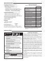
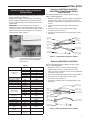
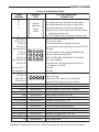
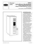
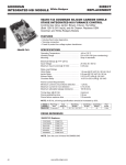
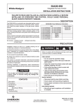
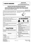
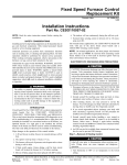
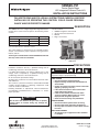
50M56U-751
Carrier Single Stage
HSI Integrated Furnace Control Kit
INSTALLATION INSTRUCTIONS
FAILURE TO READ AND FOLLOW ALL INSTRUCTIONS CAREFULLY BEFORE
INSTALLING OR OPERATING THIS CONTROL COULD CAUSE PERSONAL
INJURY AND/OR PROPERTY DAMAGE.
DESCRIPTION
The 50M56U-751 kit is a Single Stage HSI Integrated Furnace
Control kit for Carrier. This kit replaces the following Carrier
controls:
Carrier
White-Rodgers
HK42FZ004
HK42FZ009
HK42FZ016
HK42FZ007
HK42FZ011
HK42FZ034
HK42FZ008
HK42FZ013
325878-751*
The kit contains:
1 – 50M56-751 ignition control board
1 – Set of interconnect harnesses
1 – Manual
1 – Bag of accessories
50M56-751
*Universal replacement for all Carrier controls.
The control employs a microprocessor to continually monitor,
analyze, and control the proper operation of the gas burner,
inducer, and fan.
Twinning: The control board in this Kit CANNOT be twinned
with any of the Carrier circuit boards.
50M56-751
PRECAUTIONS
Installation should be done by a qualified heating and air
conditioning contractor or licensed electrician.
If in doubt about whether your wiring is millivolt, line, or low
voltage, have it inspected by a qualified heating and air
conditioning contractor or licensed electrician.
Do not exceed the specification ratings.
All wiring must conform to local and national electrical codes
and ordinances.
This control is a precision instrument, and should be handled
carefully. Rough handling or distorting components could
cause the control to malfunction.
Following installation or replacement, follow manufacturer’s
recommended installation/service instructions to ensure
proper operation.
! CAUTION
Do not short out terminals on gas valve or primary
control. Short or incorrect wiring may damage the
thermostat.
! WARNING
Failure to comply with the following warnings could result
in personal injury or property damage.
FIRE HAZARD
• Do not exceed the specified voltage.
• Replace existing control with exact model and
dash number.
• Protect the control from direct contact with water
(dripping, spraying, rain, etc.).
• If the control has been in direct contact with
water, replace the control.
• Label all wires before disconnection when
servicing controls. Wiring errors can cause
improper and dangerous operation.
• Route and secure wiring away from flame.
SHOCK HAZARD
• Disconnect electric power before servicing.
• Ensure proper earth grounding of appliance.
• Ensure proper connection of line neutral and line
hot wires.
EXPLOSION HAZARD
• Shut off main gas to appliance until installation
is complete.
www.white-rodgers.com
www.emersonclimate.com
PART NO. 37-7513B
Replaces 37-7513A
1421
SPECIFICATIONS
ELECTRICAL RATINGS [@ 77°F (25°C)]:
Input Voltage: 25 VAC 50/60 Hz
Max. Input Current @ 25 VAC: 0.45 amp
Relay Load Ratings:
Valve Relay: 1.5 amp @ 25 VAC 50/60 Hz 0.6 pf
Ignitor Relay:6.0 amp @ 120 VAC 50/60 Hz (resistive)
Inducer Relay:
2.2 FLA–3.5 LRA @ 120 VAC
Circulator Relay: 14.5 FLA–25.0 LRA @ 120 VAC
TIMING SPECIFICATIONS
(All times are in seconds, unless noted otherwise
50M56-751
Pre-Purge
30
Initial Ignitor Warm-Up
(1st 64 attempts)
17
Maximum Ignitor Warm-Up
19
Flame Current Requirements:
Minimum current to insure flame detection: 1 µa DC*
Maximum current for non-detection: 0.1 µa DC*
Maximum allowable leakage resistance: 100 M ohms
Ignition Activation Period
2
Trial for Ignition Period
4
Retries
2
*Measured with a DC microammeter in the flame probe lead
Recycles
3
OPERATING TEMPERATURE RANGE:
-40° to 176°F (-40° to 80°C)
Valve Sequence Period
12
Interpurge
60
HUMIDITY RANGE:
Post-Purge
25
MOUNTING:
Surface mount multipoise
Lockout Time
275
Timing Specs: (@ 60 Hz)
Flame Establishing Time:
Flame Failure Response Time:
maximum
0.8 sec
2.0 sec
Gases Approved: Natural, Manufactured, Mixed, Liquified
Petroleum, and LP Gas Air Mixtures are all approved for use.
Heat Delay-To-Fan-On
25/60*
Heat Delay-To-Fan-Off
90/120*
Cool Delay-To-Fan-On
2
Cool Delay-To-Fan-Off
5/90*
Auto Reset
60 minutes
*These times will vary depending on option switch
position. See OPERATION section for further
information.
INSTALLATION
! WARNING
FIRE HAZARD
• Do not exceed the specified voltage.
• Replace existing control with exact model and
dash number.
• Protect the control from direct contact with water
(dripping, spraying, rain, etc.).
• If the control has been in direct contact with
water, replace the control.
• Label all wires before disconnection when servicing controls. Wiring errors can cause improper
and dangerous operation.
• Route and secure wiring away from flame.
SHOCK HAZARD
• Disconnect electric power before servicing.
• Ensure proper earth grounding of appliance.
• Ensure proper connection of line neutral and line
hot wires.
EXPLOSION HAZARD
• Shut off main gas to appliance until installation
is complete.
! CAUTION
Do not short out terminals on gas valve or primary
control. Short or incorrect wiring may damage the
thermostat.
2
MOUNTING AND WIRING
All wiring should be installed by a qualified heating and air
conditioning contractor or licensed electrician, according to
local and national electrical codes and ordinances.
The control must be secured to an area that will experience a
minimum of vibration and remain below the maximum ambient
temperature rating of 176°F. The control is approved for
minimum ambient temperatures of -40°F.
When mounting the control, any orientation is acceptable.
Choose a location that will not damage, obstruct or place
stress on the control’s terminations, system wiring harness or
system components. After finding a suitable location, drill four
(4) 1/8” holes for mounting control. To ensure proper mounting
hole locations, use the control as a template. When drilling
the holes, take care so that the transformer, wiring harness or
other system components are not damaged. Four (4) #8 sheet
metal screws are provided to complete the installation.
Refer to the wiring diagram and wiring table when connecting
the 50M56U-751 control to other components of the system.
UL approved, 105°C rated 18 gauge, stranded, 2/64” thick
insulation wire is recommended for all low voltage safety circuit
connections.
UL approved 105°C rated 16 gauge min., stranded, 4/64”
thick insulation wire is recommended for all line voltage
connections.
After installation or replacement, follow appliance manufacturer’s
recommended installation or service instructions to ensure
proper operation.
INSTALLATION
INSTALLER MUST READ FOR PROPER
INSTALLATION
• Before removing existing control board, tag wires to assure
proper connection to new board.
• Wiring harness adaptors are included in this kit. Wiring
harness adaptors will be used when replacing existing
control as indicated below. The remaining harnesses can
be discarded.
• IMPORTANT: For low speed continuous fan speed
operation, one of the unused parked motor taps must be
connected to the low heat speed terminal. Failure to do this
will result in theblower not energizing in the constant fan
mode operation. Refer to figure 1.
Replacing HK42FZ004, HK42FZ007,
HK42FZ008, HK42FZ009, HK42FZ011,
and HK42FZ016
Use Old Style Wiring Harness Adaptor. Reference Fig. 2,
Table 1 and Wiring Diagram.
1. With power removed, connect the old style wiring adapter
(Reference Fig. 2) 9-pin connector, Inducer connector,
and Ignitor connector to the appropriate connectors in the
furnace.
2. Connect the 24 VAC and 24 VAC common wires per Table 1.
3. Connect the 12-pin, 4-pin and Flame Sense (FS)
connectors to the new control
4. Connect the remaining wires to the replacement control
per Table 1.
New Board
Flame Sense
(FS)
New Board
12-Pin Connector
Humidification
(24V)
New Board
4-Pin Connector
Blower Motor
Neutral Adapter
Figure 1
Existing Control
New Control
24V Thermostat
Terminals
G
R
Y
W
Com 24V
G
R
Y
W
C
HUM
See Harness Adaptor
N/A
SEC-1
SEC-2
Test/Twin
Test/Twin to
Com 24V
Cool
Heat
Spare-1
Spare-2
HUM-H
TH (In 12-pin connector)
TR (In 12-pin connector)
N/A
Humidification (24V)
Thermostat or 1/4” Spade
Humidification (120V)
Transformer 24 VAC (+)
Transformer 24 VAC (-)
Twin
Low Speed Continuous
Fan (120V)
Inducer Connector
of Furnace Wiring
Ignitor Connector
of Furnace Wiring
N/A
Replacing HK42FZ013, HK42FZ034
1. With power removed, connect the New style wiring
adapter (Reference Fig. 3) 11-pin In-line connector,
Inducer connector and Ignitor connector to the appropriate
connectors in the furnace.
2. Connect the 24 VAC and 24 VAC common wires per Table 1.
3. Connect the 12-pin, 4-pin and Flame Sense (FS)
connectors to the new control.
4. Connect the remaining wires to the replacement control
per Table 1.
24 VAC (+) of
furnace wiring
Selection Button (Fault)
Cool-H
HI-Heat
Park
Park
LO-Heat
Blower Neutral
COM/BLW
Power (120V)
Power Neutral
Transformer (120V)
Transformer Neutral
Electronic Air Cleaner
(120V)
Electronic Air Cleaner
Neutral
L1
L2/Neutral
PR-1
PR2/Neutral
Line Neutral
(use L adapter wire)
LINE-H
Line Neutral
XFMR-H
Line Neutral
EAC-1
EAC-H
EAC-2
Line Neutral
from 9-Pin
Connector
FS
Flame Sensor Probe
9-Pin Connector
of Furnace Wiring
Use New Style Wiring Harness Adaptor. Reference Fig 3,
Table 1 and Wiring Diagram.
Type
Blower Speed
Selection (120V)
24 VAC (-) of
Furnace Wiring
Figure 2 – Old Style Wiring Harness Adapter
For low speed continuous fan speed
connect one of the unused parked
terminals here
Table 1
Self Test
24V (+) of
Furnace Wiring
New Board
12-Pin
Connector
Humidification
(24V)
24 VAC (-) of
Furnace Wiring
9-Pin Connector
of furnace wiring
New Board
Flame Sense
(FS)
New Board
4-Pin Connector
2-Pin Inducer and
Ignitor Connector
Blower Motor
Neutral Adapter
Figure 3 – New Style Wiring Harness Adapter
3
WIRING DIAGRAM
TYPICAL SYSTEM WIRING DIAGRAM
HOT
(LINE)
NEUTRAL
(LINE)
120 VAC
24 VAC CLASS II
TRANSFORMER
TH
24 VAC
TR
50M56
COOL
LO HEAT
HI HEAT
LINE - H
XFMR - H
EAC - H
HUM - H
PARK
PARK
IND-N*
IND
IGN
IGN-N*
Optional
HUMIDIFIER
120 V
[4-Pin Connector]
IGNITOR
Y
Y
W
W
G
G
R
R
FLAME
SENSOR
PROBE
FS
HLO
MV LO
TH
PSO
Not Used
TR
HLI
GND
MV COM
PSI
Not Used
Not Used
GAS
VALVE
[12-Pin Connector]
IGN
IND
N
IGN
N
4-Pin Connector
OPTIONAL
24 V HUM
HIGH LIMIT
(N. C.)
AUX. HIGH
LIMIT (N. C.)
PRESSURE SWITCH
(N. O.)
Twinning: The control board in this kit CANNOT
be twinned with any of the Carrier circuit boards.
PSO
HLI
MV
LO
5
GND
11
TH
TR
MV
COM
12
HLO
Low Voltage (24 VAC)
IND
COMPRESSOR
CONTACTOR
THERMOSTAT
C
Line Voltage (120 VAC)
N. C. = Normally closed switch
N. O. = Normally open switch
INDUCER
CIR N
LINE N
XFMR N
HUM N
EAC N
Optional
ELECTRONIC
AIR CLEANER
120 V
LEGEND
CIRCULATOR
BLOWER
PSI
12-Pin Connector
*Use Line Neutral terminal when replacing new style control.
4
WIRING DIAGRAM
TYPICAL SYSTEM WIRING TABLE
50M56
TERMINAL
TERMINAL
TYPE
SYSTEM COMPONENT
CONNECTION
low voltage thermostat W terminal (or equivalent)
low voltage thermostat G terminal (or equivalent)
low voltage thermostat R terminal (or equivalent)
W
G
R
Y
Terminal
block with
low voltage thermostat Y terminal (or equivalent)
(2nd wire from Y terminal goes to 24 VAC HOT side of
compressor contactor coil)
24 VAC COMMON side of compressor contactor coil
captive
screws
C
HLO (Pin 1)
MV LO (Pin 2)
TH (Pin 3)
PSO (Pin 4)
Not used (Pin 5)
TR (Pin 6)
HLI (Pin 7)
GND (Pin 8)
MV COM (Pin 9)
PSI (Pin 10)
Not used (Pin 11)
Not used (Pin 12)
IND (Pin 1)
IGN (Pin 2)
IND-N (Pin 3)
IGN-N (Pin 4)
†
HLO
PSO
HLI
PSI
MV
LO
5
GND
11
TH
TR
MV
COM
12
IGN
IND
N
IND
IGN
N
high limit and flame rollout OUTPUT
gas valve first stage
24 VAC transformer (low voltage HIGH side)
pressure switch and low gas pressure switch OUTPUT
Not used
24 VAC transformer (low voltage COMMON side)
high limit and flame rollout INPUT
MUST BE RELIABLY GROUNDED TO CHASSIS
gas valve COMMON
pressure switch / low gas pressure switch INPUT
and optional 24V HUM
Not used
Not used
inducer HOT side
ignitor HOT side
inducer NEUTRAL side (or 1/4” Line Neutral)
ignitor NEUTRAL side (or 1/4” Line Neutral)
circulator blower COOL SPEED terminal
circulator blower continuous FAN terminal
circulator blower HI HEAT SPEED terminal
unused terminals
COOL
LO HEAT
spade terminal
spade terminal
HI HEAT
PARK (2 terminals)
LINE
spade terminal
spade terminal
spade terminal
XFMR
EAC (optional)
HUM (optional)
CIR N
LINE N
spade terminal
spade terminal
input voltage (120 VAC) HOT side
24 VAC transformer line voltage HOT side
electronic air cleaner HOT side
spade terminal
spade terminal
spade terminal
humidifier HOT side (120 V)
circulator blower NEUTRAL terminal
input voltage (120 VAC) NEUTRAL side
XFMR N
EAC N (optional)
HUM N (optional)
spade terminal
spade terminal
spade terminal
FS
spade terminal
24 VAC transformer line voltage NEUTRAL side
electronic air cleaner NEUTRAL side
humidifier NEUTRAL side
flame sensor probe†
Maximum recommended flame probe wire length is 36 inches.
Twinning: The control board in this kit CANNOT be twinned with any of the Carrier circuit boards.
5
OPERATION
Check-Out and Self Test
The 50M56U-751 is equipped with a self test routine used
during the control’s installation. The self test checks the
functionality of the control, Inducer, Ignitor, and blower to verify
they are in proper working order. To initiate self test sequence,
ensure thermostat is turned OFF or thermostat wires are
disconnected.
To enter self test:
● Turn on power and manually close blower door switch.
● Wait for 5 seconds.
● Slowly double click select button within 3 seconds.
Sequence is as follows:
● LED will flash 4 times then turn ON inducer motor.
● Ignitor will turn ON for several seconds, then OFF.
● Blower motor – HEAT speed will turn ON a few seconds.
● Blower motor – COOL speed will then turn on for several
seconds.
● Blower and Inducer will turn off followed by a solid LED.
NOTE
The self test functionality is available after power up and
until a Solid LED is present. During this time, the control
will ignore all active calls. If a Solid LED is present,
disconnect power for 10 seconds and refer above to enter
self test routine.
● Repair, replace or service any component that does not
work properly during the self test. The gas valve is not
energized during self test.
● Turn power off.
● Release blower door switch.
● Connect thermostat wires.
● Make appropriate option switch selections
● Install access doors.
● Turn power back on.
● Turn on gas supply to furnace.
● Run unit through one complete call for heat cycle.
OPTION SWITCHES
The option switches on the 50M56U-751 control are used to
determine the length of the heat delay-to-fan-off, heat delayto-fan-on and cool delay-to-fan-off periods. The following
illustration shows the options and the selections of the switch
positions. The switches are shown in the factory default
positions.
HEAT OFF
HEAT ON
90 SEC
25 SEC
120 SEC*
COOL OFF
5 SEC
90 SEC*
60 SEC*
*Default for most controls
HEAT MODE
When heat is required, the thermostat will send a call for heat
to the control. This starts the control’s heating sequence. The
ignitor and humidifier (optional) are powered. The ignitor is
powered after the pre-purge period.
Upon initial application of power, the ignitor warm-up time is 17
seconds. The ignitor on-time will then be increased depending
on whether or not flame is achieved. The warm-up time is
limited to a maximum of 19 seconds. During the first 64 warmup periods following power-up, the warm-up time may not be
less than 17 seconds.
6
In the event of a retry, the warm-up time will be increased by
one second and locked in at that duration. Once the warm-up
time is locked, it remains fixed until another call for heat results
in a retry, in which case the warm-up time is again increased
by one second and remains locked.
In the event of two successive retry attempts, the warm-up
time will be unlocked and set to 19 seconds. If flame is then
achieved, the warm-up time will begin adapting again with the
next call for heat. If, however, this third attempt fails to achieve
flame, the control will go into system lockout.
After the ignitor warm-up period, MV LO is energized for the
gas valve. Flame must be detected within 4 seconds. If flame is
detected, the 30-second HEAT delay-to-fan-on period begins.
The circulator and electronic air cleaner (optional) will also
energize at this time.
When the thermostat is satisfied, the gas valve is de-energized.
After proof of flame loss, the heat delay-to-fan-off period begins
and the inducer blower remains energized to purge the system
for 25 seconds. When the purge is complete, the inducer blower
is de-energized. After the delay-to-fan-off period ends, the
circulator fan and electronic air cleaner are de-energized.
If flame is not detected, the valve is de-energized, the ignitor
is turned off, and the 50M56U-751 control goes into the
“retry” sequence. The “retry” sequence provides a 60-second
wait following an unsuccessful ignition attempt (flame not
detected). After this wait, the ignition sequence is restarted
with an additional 1 second of ignitor warm-up time.
If flame is established for more than 10 seconds after ignition,
the 50M56U-751 controller will clear the ignition attempt (or
retry) counter. If flame is lost after 10 seconds, it will re-cycle
the ignition sequence.
During burner operation, a momentary loss of power of 50
milliseconds or longer will de-energize the main gas valve.
When power is restored, the gas valve will remain de-energized
and a restart of the ignition sequence will begin immediately.
A momentary loss of gas supply, flame blowout, or a shorted or
open condition in the flame probe circuit will be sensed within
2.0 seconds. The gas valve will de-energize and the control
will restart the ignition sequence. Recycles will begin and the
burner will operate normally if the gas supply returns, or the
fault condition is corrected.
If the control has gone into system lockout, it may be possible
to reset the control by a momentary power interruption of one
second or longer. Refer to SYSTEM LOCKOUT FEATURES.
COOL MODE
In a typical system, a call for cool is initiated by closing the
thermostat contacts. This energizes the 50M56U-751 control
and the compressor. The cool delay-to-fan-on period begins.
After the delay period ends, the optional electronic air cleaner
is energized, and the circulator fan is energized at cool
speed. After the thermostat is satisfied, the compressor is deenergized and the cool mode delay-to-fan-off period begins.
After the delay-to-fan-off period ends, the circulator fan and
electronic air cleaner (optional) are de-energized.
MANUAL FAN ON MODE
If the thermostat fan switch is moved to the ON position, the
circulator fan (low heat speed) and optional electronic air
cleaner are energized. When the fan switch is returned to the
AUTO position, the circulator fan and electronic air cleaner
(optional) are de-energized.
OPERATION
SYSTEM LOCKOUT AND
DIAGNOSTIC FEATURES
SYSTEM LOCKOUT FEATURES
When system lockout occurs, the gas valve is de-energized,
the circulator blower is energized at heat speed, and, if flame
is sensed, the inducer blower is energized. The diagnostic
indicator light will flash or glow continuously to indicate
system status. (System lockout will never override the
precautionary features.)
To reset the control after system lockout, do one of the
following:
1. Interrupt the call for heat or cool at the thermostat for at
least one second but less than 20 seconds (if flame is
sensed with the gas valve de-energized, interrupting the
call for heat at the thermostat will not reset the control).
2. Interrupt the 24 VAC power at the control for at least one
second. You may also need to reset the flame rollout
sensor switch.
3. After one hour in lockout, the control will automatically
reset itself.
DIAGNOSTIC FEATURES
The 50M56U-751 control continuously monitors its own
operation and the operation of the system. If a failure occurs,
the LED will indicate a failure code as shown in Troubleshooting
section. The control will store the last five fault codes. If the
failure is internal to the control, the LED will stay off or
flash 8 times. In this case, the entire control should be
replaced, as the control is not field-repairable.
Failure codes will flash the LED in the following flashpause sequences to indicate failure status (each flash will
last approximately 0.25 seconds, and each pause will last
approximately 2 seconds).
FAULT RECALL
The last five fault codes stored can be displayed on the
diagnostic LED. When the control is in standby mode (no call
for heat or cool), press the SELECT BUTTON for approximately
two seconds or until the diagnostic LED turns off. Release the
button and the LED will remain off for two seconds. Then the
fault codes will display beginning with the most recent fault
first with a two second pause between codes. After the stored
fault codes have all displayed, the LED will remain off for two
seconds and then turn on to indicate return to normal status.
While displaying the stored fault codes, the control will ignore
any new call for heat, cool or fan.
FAULT CODE RESET
The stored fault codes can be erased from memory. When
the control is in standby mode (no call for heat or cool),
press the SELECT BUTTON for five to ten seconds or until
the diagnostic LED begins to rapid flash. When the button is
released, the LED will turn off for two seconds to indicate the
codes are erased. After two seconds the LED will turn on to
indicate return to normal status. If the switch is held pressed
for over ten seconds the rapid flash will stop and the LED will
be on to indicate return to normal status.
The 50M56U-751 has only one serviceable part –an automotive
type fuse, which protects the low voltage transformer from
damage if the output is short-circuited. If the fuse has opened
up, remove whatever caused the short circuit and replace
the fuse with only a 3 Amp automotive type fuse. If the fuse
does not correct the condition, replace the entire 50M56U-751
control. There are no other user serviceable parts.
DEFINITION OF TERMS
Auto Restart – After one (1) hour of internal or external
lockout, the control will automatically reset itself and go
into an auto restart purge for 60 seconds.
Cool Delay-To-Fan-Off – The period of time between the
loss of a call for cool and the deactivation of the blower
motor at Cool speed.
Cool Delay-To-Fan-On – The period of time after a thermostat
demand for cool before energizing the circulator blower
motor at Cool speed.
Flame Failure Response Time (FFRT) – The period of time
between loss of the supervised main burner flame and
the action to shut off the gas supply.
Heat Delay-To-Fan-Off – The period of time between the
loss of a call for heat and the deactivation of the blower
motor at Heat speed.
Heat Delay-To-Fan-On – The period of time between proof
of the supervised main burner flame and the activation of
the blower motor at Heat speed.
Igniter Warm-up Time – The length of time allowed for the
igniter to heat up prior to the initiation of gas flow.
Ignition Activation Period (IAP) – The period of time
between energizing the main gas valve and deactivation
of the ignition means prior to the end of TFI.
Inter-purge – The period of time intended to allow for the
dissipation of any unburned gas or residual products of
combustion between the failed trial for ignition and the
retry period.
Post-purge Time – The period of time intended to allow for
the dissipation of any unburned gas or residual products
of combustion at the end of a furnace burner operating
cycle. Post-purge begins at the loss of flame sense.
Pre-purge Time – The period of time intended to allow for the
dissipation of any unburned gas or residual products of
combustion at the beginning of a furnace operating cycle
prior to initiating ignition.
Recycles – The additional attempts within the same
thermostat cycle for ignition after loss of the supervised
ignition source or the supervised main burner flame.
Retries – The additional attempts within the same thermostat
cycle for ignition when the supervised main burner flame
is not proven within the first trial for ignition period.
Trial for Ignition Period (TFI) – The period of time between
initiation of gas flow and the action to shut off the gas flow
in the event of failure to establish proof of the supervised
ignition source or the supervised main burner flame.
7
TROUBLESHOOTING
Red LED
Flash
Error/Condition
Comments/Troubleshooting
1
External lockout (exceeded retries)
Failure to sense flame is often caused by carbon deposits on
the flame sensor, a disconnected or shorted flame sensor lead
or a poorly grounded furnace. Carbon deposits can be cleaned
with emery cloth. Verify sensor is not contacting the burner
and is located in a good position to sense flame. Check sensor
lead for shorting and verify furnace is grounded properly. Verify
gas supply to valve, gas valve in "On" position and appliance
lighting properly. Verify flame reaches flame sensor during
ignition attempts and gas pressures are correct.
2
Pressure switch stuck closed
Pressure switch stuck closed. Check switch function, verify
inducer is turning off. Refer to wiring diagram, terminals PSI /
PSO.
3
Pressure switch stuck open
Check pressure switch function and tubing. Verify inducer is
turning on and pulling sufficient vacuum to engage switch.
Refer to wiring diagram, terminals PSI / PSO. Also check low
inlet gas pressure (if used).
4
Open high temperature limit switch or open
rollout switch
Verify continuity through limit switch circuit. Refer to wiring
diagram terminals, HLI / HLO or check open rollout switch.
5
Flame sensed with gas valve de-energized
or open rollout switch
Verify the gas valve is operating and shutting down properly.
Flame in burner assembly should extinguish promptly at the
end of the cycle. Check orifices and gas pressure.
6
Open circuit between pin 5 and 11
Verify continuity through in 5 and 11.
7
Low flame sense current
Low flame sense current is often caused by carbon deposits on
the flame sensor, a poorly grounded furnace or a mis-aligned
flame sense probe. Carbon deposits can be cleaned with
emery cloth. Check or improve furnace and module ground.
Verify sensor is located in or very near flame as specified
by the appliance manufacturer. Refer to wiring diagram FS
terminal and GND.
8
Ignitor relay fault
This flash code does not indicate a broken, disconnected or
shorted ignitor. It indicates the ignitor relay contacts on the
ignition module are not functioning properly. Replace the
ignition module.
Rapid Flash
Reversed polarity
Verify the control and furnace are properly grounded. Check
and reverse polarity (primary or secondary) if incorrect.
Continuous
On
Normal operation
No fault
Control failure
Verify power to the control, replace control if power is at the
control and no lit Red LED
Off
TECHNICAL SUPPORT: 1-888-725-9797
White-Rodgers is a business
of Emerson Electric Co.
The Emerson logo is a
trademark and service mark
of Emerson Electric Co.
www.white-rodgers.com
www.emersonclimate.com