1
MITSUBISHI
ELECTRIC
UNINTERRUPTIBLE POWER SUPPLY SYSTEM
MODEL
2033A SERIES
OWNERS / TECHNICAL MANUAL
Preface
Revision 2.5 Sep. 10, 07
ALN-H1271
MITSUBISHI ELECTRIC CORPORATION
MITSUBISHI
ELECTRIC
2033A SERIES UPS
OWNERS / TECHNICAL MANUAL
Page Number:
i
TABLE OF CONTENTS
LIST OF TABLES ................................................................................................ ii
LIST OF FIGURES .............................................................................................. iii
HOW TO USE THIS MANUAL ............................................................................ iv
1.0 INTRODUCTION........................................................................................... 1-1
1.1 SAFETY PRECAUTIONS ........................................................................... 1-2
1.2 GENERAL ..................................................................................................... 1-8
1.3 DEFINITIONS .............................................................................................. 1-9
1.4 OPERATION OVERVIEW ........................................................................... 1-10
1.5 SPECIFICATIONS ...................................................................................... 1-16
2.0 OPERATION CONTROLS AND INDICATORS ......................................... 2-1
2.1 LED DISPLAY ............................................................................................. 2-2
2.2 LIQUID CRYSTAL DISPLAY ...................................................................... 2-3
2.3 EXTERNAL SIGNAL TERMINAL BLOCK .................................................. 2-9
2.4 EXTERNAL COMMUNICATION CONNECTOR ........................................ 2-12
3.0 INSTALLATION AND OPERATION .......................................................... 3-1
3.1 TRANSPORTATION AND INSTALLATION ................................................ 3-1
3.2 INSTALLATION PROCEDURE ................................................................... 3-1
3.3 PROCEDURE FOR CABLE CONNECTIONS ............................................ 3-2
3.4 OPERATING PROCEDURES ..................................................................... 3-26
3.5 INTERNAL MAINTENANCE BYPASS SET-UP PROCEDURE ................. 3-27
3.6 MAINTENANCE BYPASS SET-UP PROCEDURE
FOR INPUT TRANS/MBP COMBINATION CABINET ......................... 3-28
4.0 RESPONSE TO UPS FAILURE ................................................................. 4-1
5.0 PARTS REPLACEMENT ............................................................................ 5-1
6.0 FAULT CODES ........................................................................................... 6-1
7.0 WARRANTY & OUT OF WARRANTY SERVICE ...................................... 7-1
MITSUBISHI ELECTRIC 2033A SERIES UPS
MITSUBISHI
ELECTRIC
2033A SERIES UPS
OWNERS / TECHNICAL MANUAL
Page Number:
ii
LIST OF TABLES
Table 1.1
UPS Installation Environment ....................................................... 1-6
Table 1.2
Rating of Bypass input circuit breaker .......................................... 1-7
Table 1.3
Power Specifications..................................................................... 1-16
Table 1.4
UPS Module Information............................................................... 1-16
Table 1.5
Input Transformer Cabinet Information (480V input).................... 1-16
Table 1.6
Input/Output Transformer Cabinet Information ........................... 1-17
(480V input, 480V output)
Table 1.7
Input Transformer/MBP Cabinet Information (480V input) ......... 1-17
Table 1.8
Detail of Specifications ................................................................. 1-18
Table 1.9
Rating of Circuit Breakers (MCCB) and Fuses............................. 1-19
Table 3.1
How to Transport and Install the System ..................................... 3-1
Table 3.2
List of UPS Weights (lb.)............................................................... 3-1
Table 3.3
Maximum Permitted Fault Current................................................ 3-2
Table 3.4a
Recommended Cable Size and .................................................... 3-6
Torque Requirements (for UPS)
Table 3.4b
Recommended Cable Size and Torque Requirements................ 3-7
(Input and output transformer field connections)
Table 3.5a
Crimp Type Compression Lug (UPS) ........................................... 3-8
Table 3.5b
Crimp Type Compression Lug (Transformer Field Terminations) .. 3-9
Table 3.6
Wiring configuration ...................................................................... 3-10
MITSUBISHI ELECTRIC 2033A SERIES UPS
MITSUBISHI
ELECTRIC
2033A SERIES UPS
OWNERS / TECHNICAL MANUAL
Page Number:
iii
LIST OF FIGURES
Figure 1.1
Single Line Diagram-Normal Operation........................................ 1-10
Figure 1.2
Single Line Diagram-Bypass Operation ....................................... 1-11
Figure 1.3
Single Line Diagram-Battery Operation........................................ 1-12
Figure 1.4
Single Line Diagram - UPS on Maintenance Bypass Operation.. 1-12
Figure 1.5
UPS Parts Location....................................................................... 1-14
Figure 2.1
Operation/Display Panel ............................................................... 2-1
Figure 2.2
Main Screen.................................................................................. 2-3
Figure 2.3
Bypass Screen.............................................................................. 2-3
Figure 2.4
Input Screen.................................................................................. 2-4
Figure 2.5
Output Voltage Screen ................................................................. 2-4
Figure 2.6
Output Current Screen.................................................................. 2-4
Figure 2.7
Trend Graph Screen ..................................................................... 2-5
Figure 2.8
Battery Screen .............................................................................. 2-5
Figure 2.9
Remote / Local Selection Screen ................................................. 2-5
Figure 2.10
Operation Menu Screen................................................................ 2-6
Figure 2.11
Battery Operation Screen ............................................................. 2-7
Figure 2.12
Battery Low Voltage Screen ......................................................... 2-7
Figure 2.13
Discharge Termination Screen ..................................................... 2-7
Figure 2.14
Failure Indication Screen .............................................................. 2-8
Figure 2.15
External Signal Terminal Block..................................................... 2-9
Figure 2.16
Control Wiring for External Contacts ............................................ 2-10
Figure 2.17
Remote "Start" Contact Connections ........................................... 2-11
Figure 2.18
External Communication Connector............................................. 2-12
Figure 3.1
UPS Terminal Designation ........................................................... 3-10
Figure 3.2
Input/Output Power Terminals ...................................................... 3-11 to 3-12
Figure 3.3
Wiring Configuration ..................................................................... 3-13 to 3-25
Figure 3.4
Start-up Menu ............................................................................... 3-26
Figure 3.5
Inverter Start / Stop....................................................................... 3-26
MITSUBISHI ELECTRIC 2033A SERIES UPS
MITSUBISHI
ELECTRIC
2033A SERIES UPS
OWNERS / TECHNICAL MANUAL
Page Number:
iv
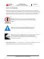
HOW TO USE THIS MANUAL
This manual is designed for ease of use, giving the user easy and quick reference to information.
This manual uses notice icons to draw attention to the user important information regarding the safe
operation and installation of the UPS. The notice icons used in this manual are explained below, and
should be taken into account and adhered to whenever they appear in the text of this manual.
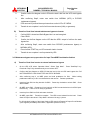
Warning: A warning notice icon conveys information provided to protect
the user and service personnel against hazards and/or possible equipment
damage.
Caution: A caution notice icon conveys information provided to protect
the user and service personnel against possible equipment damage.
Note: A Note notice icon indicates when the user should make a reference of
information regarding the UPS operation, load status and display status.
Such information is essential if Mitsubishi field service group assistance and
correspondence is required.
Safety Recommendations: If any problems are encountered while following this manual,
Mitsubishi field service group assistance and correspondence is recommended.
MITSUBISHI ELECTRIC 2033A SERIES UPS
2033A SERIES UPS
OWNERS / TECHNICAL MANUAL
MITSUBISHI
ELECTRIC
1.0
Page Number:
1-1
INTRODUCTION
The Mitsubishi Uninterruptible Power Supply (UPS) is designed to provide many years of reliable power
supply and protection from power failure, brown-outs, line noise and voltage transients.
To ensure
optimum performance of the equipment, follow the manufacturer's instructions accordingly. This manual
contains descriptions for the installation and operation procedures of the UPS. Please read this manual
carefully and retain it for future reference.
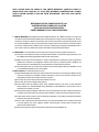
IMPORTANT SAFETY INSTRUCTIONS
RETAIN THESE INSTRUCTIONS
This manual contains important instructions for the 2033A Series Uninterruptible Power Supply Systems
that should be adhered to during installation, operation and maintenance of the UPS and batteries.
WARNING
1
Lethal voltages exist within the equipment during operation.
Observe all warning and cautions in this manual.
Failure to comply may result in serious injury or death.
Obtain a qualified service for this equipment as per instructions.
WARNING
2
In no event will MITSUBISHI be responsible or liable for either indirect or consequential
damage or injury that may come from the use of this equipment.
Any modifications without authorization by MITSUBISHI could result in personal injuries, death
or destruction of the UPS.
MITSUBISHI ELECTRIC 2033A SERIES UPS
2033A SERIES UPS
OWNERS / TECHNICAL MANUAL
MITSUBISHI
ELECTRIC
Page Number:
1-2
1.1 SAFETY PRECAUTIONS
The safety precautions are categorized as DANGER and CAUTION in this manual.
DANGER :
A dangerous situation may occur if improperly handled, leading to severe or fatal
injuries.
CAUTION: A dangerous situation may occur if improperly handled, leading to minor serious
injuries.
Note that some items described as
CAUTION
may lead to severe results depending on the
situation. Nonetheless, important information outlined in this section must be observed at all times.
DANGER
Do not dispose of the batteries in a fire as they may explode.
Do not open or break the batteries. Released electrolyte is toxic and harmful to
the eyes and skin.
A battery can present a risk of electrical shock and high short circuit current.
Observe the following minimum Safety Precautions when working on the batteries.
1)
Verify that the UPS is off and that the input power plug or wires are disconnected.
2)
Remove watches, rings or other metal objects.
3)
Use tools with insulated handles to prevent inadvertent shorts.
4)
Wear rubber gloves and boots.
5)
Do not lay tools or metal parts on top of the batteries.
6)
Determine if the battery is inadvertently grounded. If so, remove source of ground.
Contact with any part of a grounded battery can result in electrical shock. The
likelihood of such shock will be reduced if grounds are removed during installation
and maintenance.
MITSUBISHI ELECTRIC 2033A SERIES UPS
MITSUBISHI
ELECTRIC
2033A SERIES UPS
OWNERS / TECHNICAL MANUAL
Page Number:
1-3
CAUTION
PRECAUTIONS FOR INSTALLATION
Do not block the intake/exhaust ports.
-If the intake/exhaust ports are blocked, the internal temperature of the UPS will rise and
could lead to fires from battery electrolyte leakage, fire ignition or part deterioration.
Follow the UPS instruction manual carefully when installing the unit.
-Improper installation could lead to injury such as the UPS falling over, etc.
PRECAUTIONS FOR WIRING
The power supply for this unit must be three phase rated in accordance with the
equipment data plate. It must be suitably grounded.
-Failure to ground the unit could lead to electrical shocks.
PRECAUTIONS FOR USE
If a unit fault, abnormal odor or noise occurs, turn off the UPS input switch.
-Failure to do so could lead to fires.
Do not insert blunt objects or fingers, etc., in the fan.
-Failure to observe this could lead to injuries.
Do not insert blunt objects or fingers, etc., into the unit's input/output section.
-Failure to observe this could lead to electrical shocks.
Ventilate the UPS surroundings.
-Failure to do so could lead to container rupture or to explosions from the gas generated
from the battery system.
Prohibit smoking and the use of fire around the unit.
-Failure to do so could lead to injuries, damage or fires from explosions.
Do not place containers that have water or any liquids on the UPS.
-If the container tips over and the water or liquids spills, this could lead to electrical shocks
and to fires in the UPS.
Do not sit on, step on or lean on the UPS.
-Failure to observe this could lead to injuries if the UPS tips over.
MITSUBISHI ELECTRIC 2033A SERIES UPS
2033A SERIES UPS
OWNERS / TECHNICAL MANUAL
MITSUBISHI
ELECTRIC
Page Number:
1-4
CAUTION
PRECAUTIONS FOR MAINTENANCE AND INSPECTION
The inside of the UPS must be inspected or repaired only by qualified personnel.
-Failure to observe this could lead to electrical shocks, injuries, burns, smoke generation or
fires.
Periodically replace the battery.
-Batteries that have exceeded the replacement life could lead to fires from electrolyte leakage
or fire ignition.
Contact the dealer or service company for unit maintenance and repairs, and for the
replacement of defective parts.
-Opening the cover could lead to electrical shocks or burns.
PRECAUTIONS FOR BATTERY
If the battery ignites, do not use water to extinguish the fire. Instead, use a powder (ABC)
fire extinguisher.
-Use of water could cause the fire to grow.
Toxic diluted sulfuric acid in the battery.
-If electrolyte leaks from the unit, avoid contact with the skin or clothes.
If electrolyte makes contact with the skin or clothes, wash it off thoroughly with clean water.
If electrolyte makes contact with the eyes, rinse immediately and thoroughly with clean water,
and then see a doctor. The presence of sulfuric acid in the eyes could lead to blindness, and
adherence to skin could lead to burns.
OTHER PRECAUTIONS
Never use or store the unit in the following types of environment:
a)
A location having a low or high temperature, or high humidity deviated from the ambient
environment conditions described in the brochure or instruction manual.
b)
A location submerged in water or where the unit could become wet from dripping water.
c)
At an altitude higher than 9000 feet (2700 meters).
d)
In direct sunlight.
e)
Where organic solvents (gasoline, paint thinner, etc.) are stored.
f) A location that is dusty.
g)
A location containing combustible gas, corrosive gas, salt or oil mist.
h)
A location subject to vibration or impacts.
i) A location near devices that generate sparks or near heating elements.
MITSUBISHI ELECTRIC 2033A SERIES UPS
MITSUBISHI
ELECTRIC
2033A SERIES UPS
OWNERS / TECHNICAL MANUAL
Page Number:
1-5
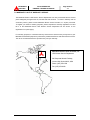
APPLICATION
This UPS shall NOT be applied to support equipment (*) that could affect
the human lives.
Special considerations are required when applying this UPS to the
equipment (**) that affect human safety and/or maintain public services.
Be sure to contact/inform MITSUBISHI if it is such a case. The application
without special consideration may cause serious accidents.
*
Medical operation room equipment
Life support equipment (artificial dialysis, incubators, etc.)
Toxic gas or smoke eliminators
Equipment that must be provided under fire laws, construction standards
or other ordinances
Equipment equivalent to the above
**
Equipment to supervise or control airways, railways, roads, sea-lanes
or other transportation.
Equipment in nuclear power plants.
Equipment to control communications.
Equipment equivalent/similar to the above mentioned.
MITSUBISHI ELECTRIC 2033A SERIES UPS
2033A SERIES UPS
OWNERS / TECHNICAL MANUAL
MITSUBISHI
ELECTRIC
WARNING
Page Number:
1-6
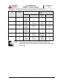
3
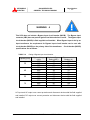
The UPS is to be installed in a controlled environment.
Improper storage and installation environment may deteriorate
insulation, shorten component life and cause malfunctions.
Keep the installation environment per standard described as follows:
UPS Installation Environment
TABLE 1.1
No.
Item
Environment standard
1
Installation
location
Indoors
2
Ambient
temperature
Minimum temperature: 32F(0C), Maximum temperature: 104F(40C) The
average temperature over any 24-hour period must be in the range 41 F (5C)
to 95F(35C).
3
Relative
humidity
The relative humidity must be held between 5 and 95%. There must be no
condensation due to temperature changes.
4
Altitude
This equipment must not be applied at altitude that exceeds 1000m(3300ft)
above seal level.
5
Dust
Dust in the room where the UPS is installed must not exceed normal
atmospheric dust levels. In particular, that dust shoud not include iron particles,
oils or fats, or organic materials such as silicone.
6
Inflammable gas There should be no inflammable/explosive gas.
Hydrogen sulfide (H2S)
No more than 0.0001 PPM
Sulfurous acid gas (SO2)
No more than 0.05 PPM
Chlorine gas (Cl2)
No more than 0.002 PPM
Ammonia gas (NH3)
No more than 0.1 PPM
Nitrous acid gas (NO2)
No more than 0.02 PPM
Nitrous oxides (NOx)
No more than 0.02 PPM
Ozone (O3)
No more than 0.002 PPM
Hydrochloric acid mist (HCl)
No more than 0.1 mg/m
MITSUBISHI ELECTRIC 2033A SERIES UPS
3
2033A SERIES UPS
OWNERS / TECHNICAL MANUAL
MITSUBISHI
ELECTRIC
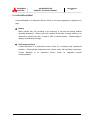
WARNING
Page Number:
1-7
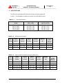
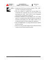
4
This UPS does not include a Bypass Input circuit breaker (MCCB). The Bypass Input
contactor (CB3) does not protect against load induced short circuits. The bypass input
circuit breaker (MCCB) is field supplied and installed. When Bypass Input is fed by an
input transformer the requirement for Bypass Input circuit breaker can be met with
circuit breaker (MCCB) on the primary side of the transformer. Circuit breaker (MCCB)
specifications are as follows:
TABLE 1.2
Rating of Bypass input circuit breaker
Capacity (kVA)
30
40
50
75
Bypass Voltage
(VAC)
Maximum Bypass
Rating (AAC)
Recommended
Breaker (A)
208
480
600
208
480
600
208
480
600
208
480
600
83
36
29
111
48
39
139
60
48
208
90
72
125
50
35
150
70
50
175
80
60
300
125
90
AC input and AC output over current protection and disconnect devices shall be field supplied
and installed. DC output over current protection and disconnect device shall be field supplied
and installed.
MITSUBISHI ELECTRIC 2033A SERIES UPS
MITSUBISHI
ELECTRIC
1.2
2033A SERIES UPS
OWNERS / TECHNICAL MANUAL
Page Number:
1-8
GENERAL
The Mitsubishi 2033A Series UPS is designed to provide continuous and clean electrical power to a
critical load. In the event of an input power failure, the UPS will supply power to the critical load for the
specified battery time.
If the input power is not restored promptly, back up power from the UPS battery permits the orderly
shutdown of equipment supported by the UPS. The UPS is simple to start up, operate and maintain.
The 2033A Series UPS is available in four (4) kVA sizes: 30, 40, 50 and 75kVA. Specifications for
each kVA model appear in Section 1.5. The principles of operation described herein are applicable to
all models.
This manual provides an overview of the 2033A Series components and their functions.
The
appearance and purpose of operator controls and indicators are described with procedures for
operation, start-up, shutdown and basic maintenance included.
MITSUBISHI ELECTRIC 2033A SERIES UPS
MITSUBISHI
ELECTRIC
1.3
2033A SERIES UPS
OWNERS / TECHNICAL MANUAL
Page Number:
1-9
DEFINITIONS
UNINTERRUPTIBLE POWER SUPPLY SYSTEM (UPS) - All components within the UPS
Module Cabinet includes the batteries which function as a system to provide continuous,
conditioned AC power to a load. This is sometimes referred to as the "System".
UPS MODULE CABINET - The metal enclosure which contains the Converter / Charger, the
Inverter, the Static Transfer Switch, the Internal Bypass line, the operator controls, and the
internal control system required to provide specified AC
power to a load.
UPS MODULE - The Converter / Charger and Inverter assemblies which, under the direction of
the internal control system and operator controls, provide specified AC power to a load.
CONVERTER / CHARGER - The UPS components which contain the equipment and controls
necessary to convert input AC power to regulated DC power required for battery charging and
for supplying power to the Inverter.
INVERTER - The UPS components which contain the equipment and controls necessary to
convert DC power from the Converter / Charger, or the battery, to AC power required by the
critical load.
STATIC TRANSFER SWITCH - The device which connects the critical load to the bypass line
when the UPS module cannot supply continuous power.
BYPASS LINE - The line which conducts electricity directly from the input power source to the critical
load during Maintenance or whenever the UPS is not completely operational.
INPUT POWER - Power provided by the electrical utility company, or auxiliary generator, which
is connected to the UPS for supplying the critical load.
MAINTENANCE BYPASS SWITCH – Internal wrap-around make-before-break rotary switch
used to provide load and personnel safety when UPS is being maintained.
MITSUBISHI ELECTRIC 2033A SERIES UPS
2033A SERIES UPS
OWNERS / TECHNICAL MANUAL
MITSUBISHI
ELECTRIC
1.4
Page Number:
1-10
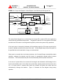
OPERATION OVERVIEW
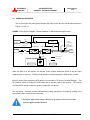
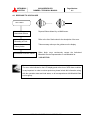
The UPS provides two power paths between the utility source and the critical load as shown in
Figures 1.1 and 1.2.
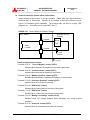
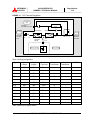
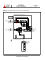
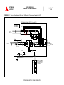
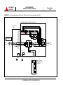
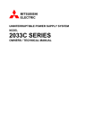
FIGURE 1.1 Single Line Diagram - Normal Operation. Load powered through inverter.
CB
Static Transfer
Switch
AC Bypass
Input
Use supplied
MCCB
CB3
CONVERTER
INVERTER
52S
AC input
Internal
Make-BeforeBreak
Maintenance
Bypass Switch
Output
CB1
52C
FC
FB
CB2
Power Flow
Not in Use
Battery cabinet
UPS Module
When the load is on the Inverter, the internal control system determines which of the two paths
supplies power to the load. During normal operation, the path through the UPS module is used.
Input AC power flows through the UPS where it is converted to DC by the Converter/Charger. This
DC power is utilized to charge the UPS battery and to provide power to the Inverter. The Inverter
converts the DC power to clean AC power to supply the critical load.
The conversion - inversion process eliminates any voltage transients or fluctuations existing in the
input power before it reaches the critical load.
* The Bypass Input circuit breaker (MCCB) for protection of the UPS and cables
are field supplied and field installed.
MITSUBISHI ELECTRIC 2033A SERIES UPS
2033A SERIES UPS
OWNERS / TECHNICAL MANUAL
MITSUBISHI
ELECTRIC
Page Number:
1-11
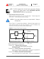
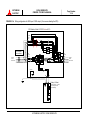
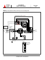
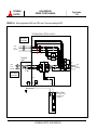
FIGURE 1.2 Single Line Diagram - Internal Bypass. Load fed through static bypass line.
CB
Static Transfer
Switch
AC Bypass
Input
Use supplied
MCCB
CB3
CONVERTER
INVERTER
52S
AC input
Internal
Make-BeforeBreak
Maintenance
Bypass Switch
Output
CB1
52C
FC
FB
CB2
Power Flow
Not in Use
Battery cabinet
UPS Module
The Internal Static Bypass line is a Hard wired line through CB3, contactor 52S which supplies the
critical load with unconditioned input power. The purpose of this line is to route power to the critical
load while the UPS module is de-energized during Start-up before the system is fully operational.
If the input power is interrupted, the battery will immediately supply the DC power required by the
Inverter to maintain continuous AC power to the load. A fully charged battery will provide power for
the specified time at the rated load, or longer, at a reduced load.
When power is restored after a low battery shutdown, the Converter/Charger automatically restarts
operation, recharges the batteries, and the Inverter is automatically restarted without operator
intervention. The load is assumed by the inverter automatically without operator intervention.
In the event of a power failure, the converter will de-energize and the batteries will discharge into the
inverter and maintain power to the critical until a) the battery capacity expires and the inverter turns
off, or b) input power is restored after which the converter will power the critical load and
simultaneously recharge the batteries.
Figure 1.3 illustrates the flow diagram during battery
operation.
MITSUBISHI ELECTRIC 2033A SERIES UPS
2033A SERIES UPS
OWNERS / TECHNICAL MANUAL
MITSUBISHI
ELECTRIC
Page Number:
1-12
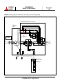
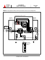
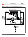
FIGURE 1.3 Single Line Diagram - Battery Operation
CB
Static Transfer
Switch
AC Bypass
Input
Use supplied
MCCB
Internal
Make-BeforeBreak
Maintenance
Bypass Switch
CB3
CONVERTER
INVERTER
52S
AC input
Output
52C
FC
CB1
FB
CB2
Power Flow
Not in Use
Battery cabinet
UPS Module
The UPS is equipped with an internal rotary type Maintenance Bypass Switch (MBS) that can be
used to divert utility power to the load during maintenance sessions. Figure 1.4 illustrates the power
path during when the MBS is in the BYPASS mode.
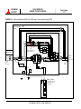
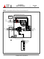
FIGURE 1.4 Single Line Diagram - UPS on Maintenance Bypass Operation.
CB
Static Transfer
Switch
AC Bypass
Input
Use supplied
MCCB
CB3
CONVERTER
INVERTER
52S
AC input
Internal
Make-BeforeBreak
Maintenance
Bypass Switch
Output
CB1
52C
FC
FB
CB2
Power Flow
Not in Use
Battery cabinet
UPS Module
MITSUBISHI ELECTRIC 2033A SERIES UPS
MITSUBISHI
ELECTRIC
2033A SERIES UPS
OWNERS / TECHNICAL MANUAL
Page Number:
1-13
The rotary maintenance bypass switch is identified as 52CS in Figure 1.4. 52CS is a two position
make-before-break transfer switch. The two positions are identified as NORMAL and BYPASS. In
the NORMAL position the load is fed by the UPS - either through the inverter or through the static
bypass line. In the BYPASS position the load is powered by an external source such as the utility or
a generator. This transfer operation must be made while the UPS is in the static bypass mode.
The transfer procedure to place the UPS in the maintenance bypass mode, and vice versa, is
outlined below:
TRANSFER FROM NORMAL MODE TO MAINTENANCE BYPASS MODE
1. With inverter running, confirm “Inverter Sync.” displayed on UPS LCD (Liquid Crystal Display) is
ON.
2. Press the inverter “STOP” key on UPS LCD.
3. Confirm UPS is on static bypass.
4. Rotate rotary switch from “NORMAL” position to “BYPASS” position.
5. Transfer is complete. UPS can now be powered down for maintenance. Load is fed by utility
or generator source. CB3 can be opened with SW2 (CB3 close/open SWITCH).
TRANSFER FROM MAINTENANCE BYPASS MODE TO NORMAL MODE
1. Confirm CB3 inside the UPS cabinet is closed (ON) with inverter running.
2. With inverter running, confirm “Inverter Sync.” displayed on UPS LCD is ON.
3. Press the inverter “STOP” key on UPS LCD.
4. Confirm UPS is on static bypass.
5. Rotate rotary switch from “BYPASS” position to “NORMAL” position.
6. Press the inverter “START” key on UPS LCD.
7. UPS will transfer to inverter automatically within a few seconds.
8. Load is now powered by the inverter.
MITSUBISHI ELECTRIC 2033A SERIES UPS
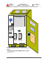
FIGURE 1.5
Page Number:
1-14
2033A SERIES UPS
OWNERS / TECHNICAL MANUAL
MITSUBISHI
ELECTRIC
UPS Parts Location
UPS module
FRONT VIEW
Converter
&
Inverter Unit
11. 52CS
13. SW2
14. CB101
CB3
5. Grounding Bar
3. CB2
2. CB1
4. External contact signal
terminal block
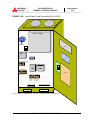
UPS module
BACKSIDE OF FRONT DOOR
Inverter
Start/Stop switch
6. Error RESET
12. Switch PCB
DPAU-55
LCD panel
Buzzer Stop
INV
START STOP
CNV SW
ON
Main PCB
UPER-V/UPFR-G
1. Emergency
bypass
switch
BUZ
OFF
SYN
BYP INV
MAINT
TEST
ON
DPAU-55
Relay PCB
RYDR-W
OFF
8.SW8
TEST switch
9.SW7
Maintenance
7. SW4
Load on Bypass switch
10. CN45
RS232C
Connector
MITSUBISHI ELECTRIC 2033A SERIES UPS
Page Number:
1-15
2033A SERIES UPS
OWNERS / TECHNICAL MANUAL
MITSUBISHI
ELECTRIC
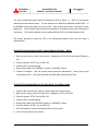
Description of Figure 1.5:
1. Emergency bypass switch (SW1)
This switch activates the bypass power supply for
emergency reasons if the UPS is turned off. Normal position is “TRANSFER is PERFORMED”.
2. AC Input circuit contactor (CB1) Contactor for converter input power.
3. Battery Disconnect circuit contactor (CB2) Contactor for battery input.
4. External contact signal terminal block Terminal block to connect contact signal input/output
lines to and from external dry contacts.
Refer to FIGURE 2.8 for details.
5. Grounding bar (E).
6. "Error reset" switch This switch resets errors resulting from alarm conditions.
(Do not
operate this switch while inverter and converter are in operation).
7. Bypass manual change-over switch (FOR SERVICE PERSONNEL ONLY)
This switch is
used to transfer the UPS from inverter to static bypass for maintenance purposes. Do not
operate it under normal operation. Transfers will be locked-out if the bypass voltage is more
than 10% of nominal. 1) Uninterrupted switching is made at the time of synchronous operation.
Switching is impossible at the time of asynchronous operation. 2) Return to "Normal" after use.
8. "Test mode" switch
This switch should be operated Authorized Service Personnel only.
9. Maintenance (Set) switch
This switch sets the UPS menu parameters.
10. RS232C connector (CN45)
11. Maintenance Bypass Switch (52CS).
12. Switches on DPAU board : FOR SERVICE PERSONNEL ONLY (Figure 1.6):
- (6) Error RESET.
- (7) SW4 (Load on Bypass Switch)
- (8) SW8 (TEST Switch): Normal=“Off” side.
- (9) SW7 (Maintenance Set Switch).
- (10) CN45 (RS232C communication connector)
13. SW2 operates contactor CB3. For maintenance of UPS only.
Normal position is “ON”.
14. Control Power circuit breaker (CB101)
MITSUBISHI ELECTRIC 2033A SERIES UPS
Page Number:
1-16
2033A SERIES UPS
OWNERS / TECHNICAL MANUAL
MITSUBISHI
ELECTRIC
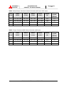
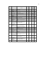
1.5 SPECIFICATIONS
The UPS name plate displays the rated kVA as well as nominal voltages and
currents. The nameplate is located on the interior side of the UPS front door.
TABLE 1.3
Power Specifications
Rated output
Input voltage
Output voltage
Power
3 ph / 3 wire
3 ph /3 or 4 wire
30kVA / 24kW
40kVA / 32kW
50kVA / 40kW
75kVA / 60kW
208, 480, or 600
208, 480, or 600
208, 480, or 600
208, 480, or 600
208, 480, or 600
208, 480, or 600
208, 480, or 600
208, 480, or 600
TABLE 1.4
UPS Module Information
HEAT LOSS
UPS
CABLE
WIDTH
DEPTH
HEIGHT
WEIGHT
(kVA)
ENTRY
(in/mm)
(in/mm)
(in/mm)
(lb.)
30
BOTTOM
35.4 / 900
29.5 / 750
70.9 / 1800
1050
11.0
40/50
BOTTOM
43.3 / 1100
29.5 / 750
70.9 / 1800
1450 /1470
13.9 / 16.6
75
BOTTOM
43.3 / 1100
29.5 / 750
70.9 / 1800
1700
23.5
TABLE 1.5
@ 208V
(kBTU/h)
Input Transformer Cabinet Information (480V input)
HEAT LOSS
UPS
CABLE
WIDTH
DEPTH
HEIGHT
WEIGHT
(kVA)
ENTRY
(in/mm)
(in/mm)
(in/mm)
(lb.)
30
TOP
16.1 / 410
29.1 / 740
70.9 / 1800
535
3.6
40
TOP / BOTTOM
24.1 / 610
29.1 / 740
70.9 / 1800
650
4.8
50
TOP / BOTTOM
24.1 / 610
29.1 / 740
70.9 / 1800
710
6.0
75
TOP / BOTTOM
24.1 / 610
29.1 / 740
70.9 / 1800
930
9.0
MITSUBISHI ELECTRIC 2033A SERIES UPS
@ 480V
(kBTU/h)
Page Number:
1-17
2033A SERIES UPS
OWNERS / TECHNICAL MANUAL
MITSUBISHI
ELECTRIC
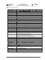
TABLE 1.6 Input/Output Transformer Cabinet Information (480V input, 480V output)
HEAT LOSS
UPS
CABLE
WIDTH
DEPTH
HEIGHT
WEIGHT
(kVA)
ENTRY
(in/mm)
(in/mm)
(in/mm)
(lb.)
30
TOP / BOTTOM
24.1 / 610
29.1 / 740
70.9 / 1800
930
6.7
40
TOP / BOTTOM
24.1 / 610
29.1 / 740
70.9 / 1800
1255
9.0
50
TOP / BOTTOM
24.1 / 610
29.1 / 740
70.9 / 1800
1350
11.2
75
TOP / BOTTOM
24.1 / 610
29.1 / 740
70.9 / 1800
1750
16.8
@ 480V
(kBTU/h)
TABLE 1.7 Input Transformer/MBP Cabinet Information (480V input)
HEAT LOSS
UPS
CABLE
WIDTH
DEPTH
HEIGHT
WEIGHT
(kVA)
ENTRY
(in/mm)
(in/mm)
(in/mm)
(lb.)
30
TOP / BOTTOM
30.3 / 700
29.1 / 740
70.9 / 1800
910
3.6
40
TOP / BOTTOM
30.3 / 700
29.1 / 740
70.9 / 1800
950
4.8
50
TOP / BOTTOM
30.3 / 700
29.1 / 740
70.9 / 1800
990
6.0
75
TOP / BOTTOM
24.1 / 610
29.1 / 740
70.9 / 1800
1310
9.0
MITSUBISHI ELECTRIC 2033A SERIES UPS
@ 480V
(kBTU/h)
2033A SERIES UPS
OWNERS / TECHNICAL MANUAL
MITSUBISHI
ELECTRIC
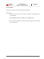
TABLE 1.8
Page Number:
1-18
Detail of Specifications
Rated Output kVA
Rated Output kW
Configuration
Voltage
Input Power Factor
Frequency
Reflected Current THD
Configuration
Voltage
Frequency
Type
Ride Through
Nominal Voltage
Minimum Voltage
Number of Cells
Configuration
Voltage
Voltage Stability
Frequency
Frequency Stability
Power Factor
Power Factor range
Voltage THD
Transient Response
Transient Recovery
Voltage Unbalance
Phase Displacement
Inverter Overload
System Overload
Bypass Overload
Withstand Rating
30
40
50
24
32
40
AC INPUT CHARACTERISTICS
3 phase, 3 wire
208 V, 480 V, 600 V
+10% ~ -15%
0.98 typical
60 Hz 5%
3% max. at 100% load; 5% max. at 50% load
STATIC BYPASS INPUT
3 phase, 3 or 4 wire
120/208 V, 277/480 V, 346/ 600 V
10%
60 Hz (3% Tracking window)
BATTERY
VRLA, Flooded Lead Acid, Nickel Cadmium
Application Specific
360 VDC
300 VDC
176 ~ 185
AC OUTPUT
3 phase, 3 or 4 wire
120/208 V, 277/480 V, 346/ 600 V
1%
60 Hz
0.01% in free running mode
0.8 nominal
0.8 ~ 1.0 lagging (within output kW rating)
2% maximum THD at 100% Linear Load
4% maximum THD at 100% non-linear load
3% maximum at 100% load step
1% maximum at loss or return of AC power
3% maximum at load transfer to/from static bypass
Less than 1 line cycle
2% maximum at 100% unbalanced load
1% maximum at 100% unbalanced load
125% for 10 minutes; 150% for 10 seconds
1000% for 1 cycle (with bypass available)
125% for 10 minutes
65kA*
*:with optional fuses (only 208V model)
Cooling
Operating Temperature
ENVIRONMENTAL
Forced Air
32 F ~ 104 F (0 C ~ 40 C).
Recommended 68 F ~ 86 F (20 C ~ 30 C)
Relative Humidity
Altitude
Location
Paint Color
5% ~ 95% Non Condensing
3300 Feet (1000 meters); 9000 feet @ 0.99 derating
Indoor (free from corrosive gases and dust)
Munsell 5Y7/1 (Beige)
MITSUBISHI ELECTRIC 2033A SERIES UPS
75
60
MITSUBISHI
ELECTRIC
2033A SERIES UPS
OWNERS / TECHNICAL MANUAL
Page Number:
1-1
Page Number:
1-19
2033A SERIES UPS
OWNERS / TECHNICAL MANUAL
MITSUBISHI
ELECTRIC
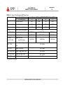
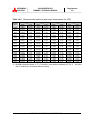
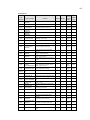
TABLE 1.9 Rating of Circuit Breakers (MCCB) and Fuses
Component(s)
Description
UPS Rating (kVA)
Component Rating @ 208V, 480V, 600V 3 phase, 60 Hz
30
40
50
75
CB1
AC Input Contactor
65A
150A
150A
220A
CB2
DC Input Contactor
65A
150A
150A
220A
CB3
Static Bypass Input Contactor
65A
150A
150A
220A
CB101
Control Power Circuit Breaker
FCU, FCV, FCW
Converter Input Fuse
140A/690Vac
180A / 660Vac
280A/660Vac
FBP
Battery Input Fuse
140A/690Vac
180A / 660Vac
280A/660Vac
(OPTION)
Bypass Input Fuse
125A/660Vac
250A/660Vac
350A/660Vac
FSU, FSV, FSW
FUD1, FUD2
(only 208V model)
Control
Power
Supply
Input
Fuse
15 A
10A / 500Vdc
FTR1, FTR2
Display Circuit Fuse
10A / 600Vac
FUS1, FUS2, FUS3
Bypass Voltage Sensor Fuse
10A / 600Vac
FZS1, FZS2, FZS3
Bypass Input Zener Fuse
30A / 600Vac
FBS1, FBS2
CB3 Coil Input Fuse
10A / 600Vac
* Rating would be changed.
MITSUBISHI ELECTRIC 2033A SERIES UPS
Page Number:
2-1
2033A SERIES UPS
OWNERS / TECHNICAL MANUAL
MITSUBISHI
ELECTRIC
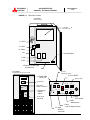
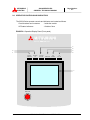
2.0 OPERATOR CONTROLS AND INDICATORS
The 2033A Series operator controls and indicators are located as follows:
Circuit breakers and contactors
: Inside the module
UPS status indicators
: Outside of door
FIGURE 2.1 Operation/Display Panel (Front panel)
MITSUBISHI
22003333A
AS
SE
ER
RIIE
ES
SU
UP
PS
S
3
4
5
6
2
1
LOAD ON
INVERTER
BATTERY
OP.
LOAD ON
BYPASS
OVERLOAD
LCD
FAILURE
UPS
FAILURE
7
EMRG.STOP
MITSUBISHI ELECTRIC 2033A SERIES UPS
2033A SERIES UPS
OWNERS / TECHNICAL MANUAL
MITSUBISHI
ELECTRIC
Page Number:
2-2
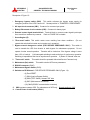
2.1 LED Display
1)
Load on inverter (green)
Turned on when power is supplied from inverter to the critical load.
(Indicates the state of transfer switch "52C" of inverter.)
2)
Battery operation (yellow)
Turned on when the battery is operating following an AC power failure..
3)
Load on bypass (yellow)
Turned on when power is supplied through bypass to load devices.
(Indicates the state of transfer switch "52S" of bypass.)
4)
Overload (yellow)
Turned on when an overload has occurred to the system.
5)
LCD failure [ LCD FAIL ](red)
Turned on when an error occurs on the LCD.
6)
UPS failure [ UPS FAIL ](red) [Annunciator: intermittent or constant tones]
Turned on when an error occurs on the system. In this case, the details of error are indicated on
the display panel.
MITSUBISHI ELECTRIC 2033A SERIES UPS
MITSUBISHI
ELECTRIC
2033A SERIES UPS
OWNERS / TECHNICAL MANUAL
Page Number:
2-3
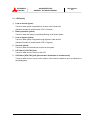
2.2 Liquid Crystal Display ( 7 in Figure 2.1 )
The Liquid Crystal Display (LCD) panel indicates the power flow, measured values, operational
guidance, data record and error messages. The LCD panel is back-lit to facilitate viewing in
different ambient lighting conditions. The LCD will automatically clear if the keyboard is not
activated for 3 minutes. The ERROR indicator is cleared after 24 hours and can be reproduced
by pressing any key on the panel.
2.2.1 Menu’s
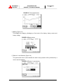
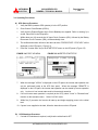
A) MAIN MENU (Figure 2.2)
The LCD panel indicates the power flow, measured values and remote operation mode. The
LCD panel shows the power flow. This allows the user to verify the status of the UPS Module.
FIGURE 2.2 Main screen
The following will be displayed when the measuring point button on LCD panel is pressed.
1) Bypass Voltage (Figure 2.3)
The voltages displayed are the Bypass input voltages (line-to-line) between phases A-B,
B-C, C-A and frequency of the Bypass line. Line to neutral voltages A-N, B-N, C-N are
measured on 4 wire systems only.
FIGURE 2.3 Bypass screen
MITSUBISHI ELECTRIC 2033A SERIES UPS
MITSUBISHI
ELECTRIC
2033A SERIES UPS
OWNERS / TECHNICAL MANUAL
Page Number:
2-4
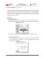
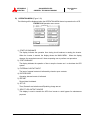
2) Input Voltage and Current (Figure 2.4)
The voltages displayed are the RMS AC input voltages (line-to-line) between phases A-B,
B-C C-A and frequency of the AC input line. The RMS values of phases A, B and C
currents are also displayed.
FIGURE 2.4 Input screen
3) Output Voltage, Output Current and Trend Graph
The voltages displayed on the LCD include the inverter output voltages A-B, B-C, C-A.
Line to neutral voltages A-N, B-N, C-N are displayed on 4 wire systems only. Inverter
output frequency is also displayed. (Figure 2.5)
The currents displayed and the RMS values and Peak Values of Phases A, B, C. N-current
(Neutral) is display on a 4 wire system only. (Figure 2.6)
The Trend Graph displays the Effective power values and the Reactive power values.
(Figure 2.7)
FIGURE 2.5 Output voltage screen
FIGURE 2.6 Output current screen
MITSUBISHI ELECTRIC 2033A SERIES UPS
2033A SERIES UPS
OWNERS / TECHNICAL MANUAL
MITSUBISHI
ELECTRIC
Page Number:
2-5
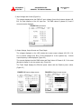
FIGURE 2.7 Trend graph screen
4) Battery (Figure 2.8)
This displays the charging, discharging or float mode of the battery, battery current and
battery voltage.
FIGURE 2.8 Battery screen
5) Remote / Local Selection (Figure 2.9)
The system asks user to select whether the start & stop operation will be performed by a
local or remote operation.
FIGURE 2.9 Remote / Local selection
MITSUBISHI ELECTRIC 2033A SERIES UPS
2033A SERIES UPS
OWNERS / TECHNICAL MANUAL
MITSUBISHI
ELECTRIC
Page Number:
2-6
B) OPERATION MENU (Figure 2.10)
The following will be displayed when the OPERATION MENU button is pressed on the LCD
FIGURE 2.10 Operation menu screen
1) START-UP GUIDANCE
The display indicates the operation from closing circuit breakers to starting the inverter.
When the inverter is started, the display shows the MAIN MENU. When the display
changes, the annunciator sounds 3 times requesting user to perform next procedure.
2) STOP GUIDANCE
The display indicates the operation of how to stop the inverter and to shutdown the UPS
system.
3) EXTERNAL CONTACT INPUT
The input of external contacts is indicated by closed or open contacts.
4) DATA RECORD
Operation data and events is indicated.
5) REPORT
Record data is indicated.
6) SET UP
Time, Remote/Local selection and Equalizing charge are set.
7) SELECT UPS OUTPUT SOURCE
This display is used to transfer the UPS from inverter to static bypass for maintenance
purposes.
MITSUBISHI ELECTRIC 2033A SERIES UPS
MITSUBISHI
ELECTRIC
2033A SERIES UPS
OWNERS / TECHNICAL MANUAL
Page Number:
2-7
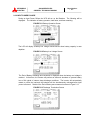
2.2.2 INPUT POWER FAILURE
During an Input Power Failure the UPS will run on the Batteries. The following will be
displayed. The indication of battery operation, load factor, and time remaining.
FIGURE 2.11 Battery Operation Screen
The LCD will display a battery low voltage announcement when battery capacity is near
depletion.
FIGURE 2.12 Battery Low Voltage Screen
The End of Battery Discharge announcement is displayed when the battery end voltage is
reached. At that time, the inverter will perform an electronic shutdown to prevent battery
loss of life typical of extreme deep discharge conditions. The inverter will automatically
restart to power the load and the batteries will be simultaneously recharged after input
power is restored. Details of the End of Battery announcement is shown in Figure 2.13.
FIGURE 2.13 Discharge Termination Screen
MITSUBISHI ELECTRIC 2033A SERIES UPS
MITSUBISHI
ELECTRIC
2033A SERIES UPS
OWNERS / TECHNICAL MANUAL
Page Number:
2-8
2.2.3 FAULT INDICATION (Figure 2.14)
The display shows a fault code, description of fault and a guidance of what action is to take
place by the user. A maximum of 10 faults are displayed at the same time.
When an input power failure occurs during the fault Indication, the fault indication and input
power failure are alternatively displayed at 5 second intervals.
FIGURE 2.14 Failure indication screen
MITSUBISHI ELECTRIC 2033A SERIES UPS
2033A SERIES UPS
OWNERS / TECHNICAL MANUAL
MITSUBISHI
ELECTRIC
Page Number:
2-9
2.3 External Signal Terminal Block
The UPS is equipped with a series of input/output terminals for the external annunciation of
alarms and the remote access of certain UPS functions. A functional description of the
input/output port is presented below. Layout of terminals is shown in Figure 2.15
FIGURE 2.15 External Signal Terminal Block
1
2
3
4
5
6
7
8
9
10
11
12
13
14
15
16
17
18
19
20
21
22
23
24
25
26
27
28
29
30
31
32
33
34
35
(User supplied dry contact)
EMERGENCY STOP
IN0: REMOTE INVERTER STOP
IN1: REMOTE INVERTER START
IN2: POWER DEMAND
IN3: ASYNCHRONOUS
IN4: BATTERY TEMP. HIGH
IN5: ROOM TEMP. HIGH
OUT0: LOAD ON BYPASS
OUT1: LOAD ON INVERTER
OUT2: BATTERY OPERATION
OUT3: CONVERTER OPERATION
UPS FAILURE
UPS FAILURE
OUT4: BATTERY LOW VOLTAGE
OUT5: OVERLOAD
UPS
MITSUBISHI ELECTRIC 2033A SERIES UPS
Page Number:
2-10
2033A SERIES UPS
OWNERS / TECHNICAL MANUAL
MITSUBISHI
ELECTRIC
A) Output Contacts(for external alarm annunciation)
Output contacts consist of form “A” dry type contacts. Rated value of all output contacts is
120Vac/0.5Aac or 30Vdc/1Adc. Operate all dry contacts at their rated values or lower.
Figure 2.16 illustrates typical installation. The external relay can also be a lamp, LED,
computer, etc. Connection not to exceed NEC Class 2.
FIGURE 2.16 Control Wiring for External Contacts
UPS Cabinet
External to UPS
Cabinet
Terminal
Relay
Coil
Relay
Contact
Terminal
Power
Source
Details of output alarm contacts :
User supplied
Terminals 22 to 21 "Load on Bypass" contact (OUT0)
Activated when the power is supplied from the static bypass input.
Terminals 24 to 26 "Load on Inverter" contact (OUT1)
Activated when the power is supplied by the inverter.
Terminals 25 to 26 "Battery Operation" contact (OUT2)
Activated when the battery is operating following an AC power failure.
Terminals 27 to 28 “Converter Operation” contact (OUT3)
Activated when the converter is operating.
Terminals 29 to 30 "UPS failure" contact
Activated when a major fault has occurred to the system.
Terminals 31 to 32 "UPS failure" contact
Activated when a major fault has occurred to the system.
Terminals 34 to 33 "Battery Low Voltage" contact (OUT4)
Activated when DC voltage dropped below discharge end during inverter
operation.
Terminals 35 to 34 "Overload" contact (OUT5)
Activated when an overload has occurred to the system.
MITSUBISHI ELECTRIC 2033A SERIES UPS
NOTE:
Page Number:
2-11
2033A SERIES UPS
OWNERS / TECHNICAL MANUAL
MITSUBISHI
ELECTRIC
The UPS is equipped with a selectable output contact feature. The above
alarms are the default settings. Contact MITSUBISHI ELECTRIC
POWER PRODUCTS, INC. for set-up information.
B) Input Contacts(for remote access of UPS)
External contacts are provided by the user of the UPS system. Terminal voltage at the
UPS is 24Vdc. Provide external dry contact accordingly.
CAUTION:
Do not apply voltage to remote access input terminals. Damage to
UPS may result.
Refer to Figure 2.17 for typical wiring configuration. Although this figure applies to the
remote start/stop terminals, the same wiring arrangement is used for emergency stop;
asynchronous command; power demand; battery temperature high.
FIGURE 2.17 Remote "Start" Contact Connections
UPS Cabinet
External to UPS
Cabinet
Relay
Start
Coil
Start
Switch
Common
24 VDC
Relay Coil current : 8.3mA
Use Momentary Switches
Details of input contacts for remote access :
User supplied
Terminals 7 to 8
"Emergency Stop" contact input
Used to perform a remote UPS emergency power off (EPO).
The load will be dropped.
Terminals 9 to 10 Remote "Inverter Stop” input terminal (IN0)
Used to stop inverter from a remote location. UPS must be programmed for
remote operation. Refer to Operations Menu for procedure.
Terminals 11 to 12 Remote "Inverter Start” input terminal (IN1)
Used to start inverter from a remote location. UPS must be programmed for
MITSUBISHI ELECTRIC 2033A SERIES UPS
Page Number:
2-12
2033A SERIES UPS
OWNERS / TECHNICAL MANUAL
MITSUBISHI
ELECTRIC
remote operation. Refer to Operations Menu for procedure.
Terminals 13 to 14 "Power Demand Command" contact input (IN2)
Used to control the input current limit to the UPS converter (usually during
generator operation). Power demand is turned ON when the contact is closed.
Power demand is turned OFF when the contact is open.
Terminals 15 to 16 "Asynchronous Command" contact input (IN3)
Used to create an asynchronous condition between the static bypass source and
the inverter. Asynchronous condition is enabled when the switch is closed.
Asynchronous condition is disabled when the switch is opened.
Terminals 17 to 18 “BATTERY TEMP. HIGH” contact input (IN4)
Input fed by a thermocouple that monitors battery temperature. The converter
float voltage level is reduced for battery over-temperature conditions. External
thermocouple is user supplied
Terminals 19 to 20 “ROOM TEMP. HIGH” contact input (IN5)
Input fed by a thermocouple that monitors room temperature.
External thermocouple is user supplied.
NOTE : In all cases, a switch having a plate is recommended in order to reduce
possibility of accidental operation.
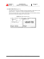
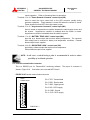
2.4 External communication connector
This is a RS232C port for “DiamondLink” monitoring software.
The layout of connector is
shown in Figure 2.18. Connections not to exceed NEC Class 2.
FIGURE 2.18 External communication connector
CN45
Pin 2. TXD : Transmit data
D-SUB 25Pin
Pin 3. RXD : Receive data
Pin 7. GND : Signal ground
1
14
15
16
17
18
19
20
21
22
23
24
25
2
Pin 9. 5VS : DC5V supply
3
Pin 10. GND : Ground
4
5
Pin 11. 5VS : DC5V supply
6
7
8
9
10
11
12
13
PCB DPAU-
MITSUBISHI ELECTRIC 2033A SERIES UPS
Page Number:
3-1
2033A SERIES UPS
OWNERS / TECHNICAL MANUAL
MITSUBISHI
ELECTRIC
3.0 INSTALLATION AND OPERATION
3.1 Transportation and Installation
TABLE 3.1 How to transport and install the system
Transportation
Installation
Transport unit with forklift.
Using the holes (4 - 24) pre drilled into the
Use eye bolts (supplied) to carry with
UPS channel base, anchor the unit using
overhead crane.
appropriate hardware.
Note : Do not transport in a horizontal position.
Cabinets should be maintained
upright within +/- 15° during handling.
3.2 Installation Procedure
A) Note the load tolerance of the floor
Refer to Table 3.2 for list of weights of UPS’s.
TABLE 3.2 List of UPS weights
UPS Capacity (kVA)
30
40
50
75
Weight (lb.)
1050
1450
1470
1700
B) Minimum clearance required for ventilation
Right side
1.0" (25 mm) (not required when sidecars are used)
Left side
1.0" (25 mm) (not required when sidecars are used)
Back side
0.0" (0.0 mm)
Top side
23.6" (600 mm) (for air flow)
C) Space requirement for routine maintenance
Allow the following space at the time of installation.
Front
39.4" (1000 mm)
Sides
0.0" (0.0 mm)
Rear
0.0" (0.0 mm)
MITSUBISHI ELECTRIC 2033A SERIES UPS
Page Number:
3-2
2033A SERIES UPS
OWNERS / TECHNICAL MANUAL
MITSUBISHI
ELECTRIC
D) External Battery Supply
Please refer to the following when installing batteries:
1.
The customer shall make reference to the battery manufacturer's installation
manual for battery installation and maintenance instructions.
2.
The maximum permitted fault current from the remote battery supply and the DC
voltage rating of the battery supply over-current protective device are shown in
Table 3.3.
TABLE 3.3 Maximum Permitted Fault Current
UPS CAPACITY
DC VOLTAGE RATING
MAXIMUM FAULT
(kVA)
(V)
CURRENT (A)
30
360
25,000
40
360
30,000
50
360
30,000
75
360
30,000
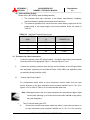
3.3 Procedure for Cable Connections
I.
Confirm the capacity of the UPS being installed. Identify the input/output power terminal
blocks as shown in the appropriate Figure 3.1 through Figures 3.2-a~b.
II.
Connect the grounding conductor from the input service entrance to the UPS ground bar
and associated equipment per the National Electric Code (NEC) and applicable codes
per authority having jurisdiction (AHJ).
III.
Connect Input Power Cables:
For configurations which utilize an input transformer connect cables from the input
service entrance to the input transformer power terminals identified as H1, H2, H3 in
figures 3.3-c~m. Refer to Table 3.4.b for recommended cable sizes.
Note: When Bypass Input is fed by an input transformer the requirement for Bypass Input
circuit breaker (Warning 2) can be met with circuit breaker (MCCB) on the primary
side of the transformer.
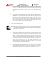
1.
Two (2) sources feeding the UPS:
A.
Connect the converter input power cables from either 1) input service entrance, or
2) input transformer power terminals identified as X1, X2, X3 to the converter
MITSUBISHI ELECTRIC 2033A SERIES UPS
Page Number:
3-3
2033A SERIES UPS
OWNERS / TECHNICAL MANUAL
MITSUBISHI
ELECTRIC
input power terminals identified as A10, B10, C10 in Figures 3.2-a~b and Figures
3.3-a~m. Input cables must be sized for an ampacity larger than the maximum
input drawn by the converter.
Refer to Table 3.4.a for recommended cable
sizes.
B.
Confirm that an external bypass input circuit breaker (MCCB) is installed (refer to
WARNING 2). Connect the bypass input power cables from the input service
entrance to the bypass input power terminals identified as A30, B30, C30 and
N60 in Figures 3.2-a~b and Figures 3.3-a~m.
Bypass input cables must be
sized for an ampacity larger than the maximum output current capacity of the
UPS. Refer to Table 3.4 a for recommended cable sizes.
2.
One (1) source feeding the UPS:
Note: When utilizing an output transformer the neutral is not required for the Bypass Input.
The neutral for the load will be generated at the secondary of the output transformer.
Refer to Figures 3.3-h and 3.3-m.
A.
Confirm that an external input circuit breaker sized to protect both the converter
input and the bypass lines is installed. Consult equipment nameplate for current
ratings.
Connect the bypass input power cables from either 1) input service
entrance, or 2) input transformer power terminals identified as X1, X2, X3 and X0
to the bypass input power terminals identified as A30, B30, C30 and N60 in
Figures 3.2-a~b and Figures 3.3-a~m.
Input cables must be sized for an
ampacity larger than the maximum current capacity of the UPS. Refer to Table
3.4.a. “Input Side” for recommended cable sizes.
B.
Using adequately sized conductors per Table 3.4.a “Input Side” and referring to
the appropriate figure identified in Figures 3.2-a~b and Figures 3.3-a~l, jumper
bypass terminals A30, B30, C30 to converter input terminals A10, B10, C10.
MITSUBISHI ELECTRIC 2033A SERIES UPS
MITSUBISHI
ELECTRIC
3.
2033A SERIES UPS
OWNERS / TECHNICAL MANUAL
Page Number:
3-4
For configurations that utilize an Input Trans/MBP Combination Cabinet:
A.
Connect the bypass input power cables from Bypass Input Isolation Breaker
(MBP SW1) Terminals A, B and C to the UPS bypass input power terminals
identified as A30, B30 and C30.
Connect Input Transformer/MBP Neutral to
UPS Terminal N60. Refer to Figures 3.2-a~b and Figure 3.3.e. Bypass input
cables must be sized for an ampacity larger than the maximum input current
drawn by the UPS converter.
Refer to Table 3.4.a
“Input Side” for
recommended cable sizes.
B.
Using adequately sized conductors per Table 3.4.a “Input Side” and referring to
the appropriate figure identified in Figures 3.2-a~b and Figure 3.3.e, jumper
bypass terminals A30, B30, C30 to converter input terminals A10, B10, C10.
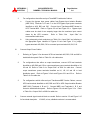
IV.
Connect Output Power Cables:
1.
Referring to Figures 3.2-a~bconnect UPS load terminals A60, B60, C60 and N60 to
load distribution panel. Refer to Table 3.4.a for cable sizes.
2.
For configurations that utilize an output transformer, connect UPS load terminals
identified as A60, B60 and C60 to output transformer power terminals identified as X1,
X2 and X3. Refer to Table 3.4.a “Output Side” at 208V for cable size. Connect
output transformer power terminals identified as H1, H2, H3 and H0 to load
distribution panel. Refer to Figures 3.2-a~b and Figures 3.3-h and 3.3-m. Refer to
Table 3.4.b for cable size.
3.
For configurations which utilize an Input Transformer/MBP Combo Cabinet, connect
UPS load terminals identified as A60, B60 and C60 to UPS Output Isolation Breaker
(MBP SW3) Terminals A, B and C. Connect MBP Load Terminals A, B, C and
neutral to load distribution panel. Refer to Figures 3.2-a~b and Figure 3.3.e. Refer
to Table 3.4.a “Output Side” at 208V for cable size.
V.
Connect external signal terminal block as needed. Refer to section 2.3 and Figure 2.15
for functional description. 12 AWG, or less, shielded conductor is recommended.
MITSUBISHI ELECTRIC 2033A SERIES UPS
MITSUBISHI
ELECTRIC
2033A SERIES UPS
OWNERS / TECHNICAL MANUAL
Page Number:
3-5
NOTES: 1. Confirm that all UPS internal contactors (breakers) "CB1", "CB2",
and "CB3" are open before energizing UPS.
2. UPS power terminals are supplied with stud type fittings. It is
recommended that compression lugs be used to fasten all UPS
input/output power cables.
Refer to Table 3.5.a for recommended
compression lugs and appropriate crimping tool.
3. Transformer terminals are stud type fittings with 2 hole NEMA
pattern. It is recommended that compression lugs be used to fasten all
transformer field installed power cables. Refer to Table 3.5.b for
recommended compression lugs and appropriate crimping tool.
4. Input Trans/MBP Breakers are equipped with mechanical terminals
for field connections.
5. If three-wire source for input and bypass input is utilized, the neutral
conductor in the UPS must be bonded to ground.
MITSUBISHI ELECTRIC 2033A SERIES UPS
2033A SERIES UPS
OWNERS / TECHNICAL MANUAL
MITSUBISHI
ELECTRIC
Table 3.4.a
UPS
Capacity
(kVA)
30kVA
(208V)
30kVA
(480V)
30kVA
(600V)
40kVA
(208V)
40kVA
(480V)
40kVA
(600V)
50kVA
(208V)
50kVA
(480V)
50kVA
(600V)
75kVA
(208V)
75kVA
(480V)
75kVA
(600V)
Page Number:
3-6
Recommended cable size and torque requirements (for UPS)
Input Side
* 1, 2
Cable
Torque
Size
(in. lbs)
1 AWG
100-135
or larger
in. lbs
1 AWG
100-135
or larger
in. lbs
1 AWG
100-135
or larger
in. lbs
1/0 AWG
200-269
or larger
in. lbs
1/0 AWG
200-269
or larger
in. lbs
1/0 AWG
200-269
or larger
in. lbs
2/0 AWG
200-269
or larger
in. lbs
2/0 AWG
200-269
or larger
in. lbs
2/0 AWG
200-269
or larger
in. lbs
350MCM
347-469
or larger
in. lbs
350MCM
347-469
or larger
in. lbs
350MCM
347-469
or larger
in. lbs
Output Side
* 1, 2
Cable
Torque
Size
in. lbs
1 AWG
100-135
or larger
in. lbs
8 AWG
100-135
or larger
in. lbs
8 AWG
100-135
or larger
in. lbs
1/0 AWG
100-135
or larger
in. lbs
4 AWG
100-135
or larger
in. lbs
6 AWG
100-135
or larger
in. lbs
2/0 AWG
100-135
or larger
in. lbs
3 AWG
100-135
or larger
in. lbs
4 AWG
100-135
or larger
in. lbs
350 MCM
347-469
or larger
in. lbs
1 AWG
347-469
or larger
in. lbs
3 AWG
347-469
or larger
in. lbs
Bypass Side
* 1, 2
Cable
Torque
Size
in. lbs
1 AWG
100-135
or larger
in. lbs
8 AWG
100-135
or larger
in. lbs
8 AWG
100-135
or larger
in. lbs
1/0 AWG
100-135
or larger
in. lbs
4 AWG
100-135
or larger
in. lbs
6 AWG
100-135
or larger
in. lbs
2/0 AWG
100-135
or larger
in. lbs
3 AWG
100-135
or larger
in. lbs
4 AWG
100-135
or larger
in. lbs
350 MCM
347-469
or larger
in. lbs
1 AWG
347-469
or larger
in. lbs
3 AWG
347-469
or larger
in. lbs
DC Input Side
* 1, 2
Cable
Torque
Size
in. lbs
4 AWG
100-135
or larger
in. lbs
4 AWG
100-135
or larger
in. lbs
4 AWG
100-135
or larger
in. lbs
2 AWG
200-269
or larger
in. lbs
2 AWG
200-269
or larger
in. lbs
2 AWG
200-269
or larger
in. lbs
1/0 AWG
200-269
or larger
in. lbs
1/0 AWG
200-269
or larger
in. lbs
1/0 AWG
200-269
or larger
in. lbs
4/0 AWG
347-469
or larger
in. lbs
4/0 AWG
347-469
or larger
in. lbs
4/0 AWG
347-469
or larger
in. lbs
*1 - Voltage drop across power cables not to exceed 2% of nominal source voltage.
*2 - Allowable capacities based on 75 C insulation at an ambient temperature of 30 C. Not more
than 3 conductors in a raceway without de-rating.
MITSUBISHI ELECTRIC 2033A SERIES UPS
MITSUBISHI
ELECTRIC
2033A SERIES UPS
OWNERS / TECHNICAL MANUAL
Page Number:
3-7
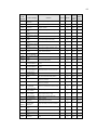
Table 3.4.b Recommended cable size and torque requirements
(input and output transformer field connections)
UPS
Capacity
(kVA)
30kVA
Primary
Voltage
480V
30kVA
600V
40kVA
480V
40kVA
600V
50kVA
480V
50kVA
600V
75kVA
480V
75kVA
600V
Input Transformer
*1,2
Recommended
Cable
Breaker (A)
Size
50
6 AWG
or larger
40
6 AWG
or larger
70
4 AWG
or larger
50
6 AWG
or larger
80
3 AWG
or larger
70
4 AWG
or larger
125
1 AWG
or larger
100
3 AWG
or larger
Torque
(in. lbs)
60
in. lbs
60
in. lbs
144
in. lbs
144
in. lbs
144
in. lbs
144
in. lbs
144
in. lbs
144
in. lbs
Output Transformer
*1,2
Secondary
Cable
Voltage
Size
480V
6 AWG
or larger
600V
6 AWG
or larger
480V
4 AWG
or larger
600V
6 AWG
or larger
480V
3 AWG
or larger
600V
4 AWG
or larger
480V
1 AWG
or larger
600V
3 AWG
or larger
Torque
in. lbs
60
in. lbs
60
in. lbs
144
in. lbs
144
in. lbs
144
in. lbs
144
in. lbs
144
in. lbs
144
in. lbs
*1 - Voltage drop across power cables not to exceed 2% of nominal source voltage.
*2 - Allowable capacities based on 75 C insulation at an ambient temperature of 30 C. Not more
than 3 conductors in a raceway without de-rating.
MITSUBISHI ELECTRIC 2033A SERIES UPS
Page Number:
3-8
2033A SERIES UPS
OWNERS / TECHNICAL MANUAL
MITSUBISHI
ELECTRIC
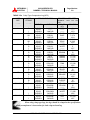
TABLE 3.5a Crimp Type Compression Lug (UPS)
WIRE
SIZE
WIRE
STRAND
(CODE)
CLASS
VENDOR
CAT. NO.
8
B
BURNDY
ILSCO
BURNDY
BURNDY
ILSCO
BURNDY
BURNDY
ILSCO
BURNDY
BURNDY
ILSCO
BURNDY
BURNDY
ILSCO
BURNDY
BURNDY
ILSCO
BURNDY
BURNDY
ILSCO
BURNDY
BURNDY
ILSCO
BURNDY
BURNDY
ILSCO
BURNDY
BURNDY
ILSCO
BURNDY
BURNDY
ILSCO
BURNDY
BURNDY
ILSCO
BURNDY
BURNDY
ILSCO
BURNDY
YA8C-TC14
-------YA8C-LB
YA6C
CRB-6L
YA5C-LB
YA4C
CRB-4L
YA3C-LB
YA3C
CRA-3L
YA2C-LB
YA2C
CRB-2L
YA1C-LB
YA1C
CRA-1L
YA25-LB
YA25
CRA-1/OL
YA26-LB
YA26
CRA-2/OL
YA27-LB
YA27
CRB-3/OL
YA28-LB
YA28
CRB-4/OL
YA29-LB
YA29
CRA-250L
YA30-LB
YA30-L7
CRA-30OL
YA32-LB
YA31-L7
CRA-350L
YA34-LB
250 MCM
I
B
B/I
I
B
B/I
I
B
B
I
B
B
I
B
B
I
B
B
I
B
B
I
B
B
I
B
B
I
B
300 MCM
I
B
350 MCM
I
B
6
4
3
2
1
1/0
2/0
3/0
4/0
I
NOTE:
RECOMMENDATION
CRIMP TOOL REQUIRED
BURNDY TYPE Y35 OR
Y46
COLOR
DIE INDEX
KEY
RED
49
--------------------1013
BLUE
7 / 374
BLUE
7 / 374
-------1014
GRAY
8 / 346
GRAY
8 / 346
-------1016
WHITE
9
WHITE
9
-------1017
BROWN
10
BROWN
10
-------1018
GREEN
11 / 375
GREEN
11 / 375
-------1019
PINK
12 / 348
PINK
12 / 348
-------1020
BLACK
13
BLACK
13
-------1021
ORANGE
14 / 101
ORANGE
14 / 101
-------1022
PURPLE
15
PURPLE
15
-------1023
YELLOW
16
YELLOW
16
-------1024
WHITE
17 / 298
WHITE
17 / 298
-------1026
RED
18 / 324
RED
18 / 324
-------1027
When using crimp type lugs, the lugs should be crimped to the specifications
given in the manufacturer's instructions for both crimp tool and lug.
MITSUBISHI ELECTRIC 2033A SERIES UPS
Page Number:
3-9
2033A SERIES UPS
OWNERS / TECHNICAL MANUAL
MITSUBISHI
ELECTRIC
TABLE 3.5.b Crimp Type Compression Lug (Transformer Field Terminations)
WIRE
SIZE
WIRE
STRAND
(CODE)
CLASS
VENDOR
CAT. NO.
8
B
6
I
B
BURNDY
ILSCO
BURNDY
BURNDY
ILSCO
BURNDY
BURNDY
ILSCO
BURNDY
BURNDY
ILSCO
BURNDY
BURNDY
ILSCO
BURNDY
BURNDY
ILSCO
BURNDY
---------------------YA6C-2LN
-------YA6C-2N
YA4C-2LN
CRC-4L2
------YA3C-2N
------------YA2C-2LN
CRC-2L2
YA2C-2N
YA1C-2LN
CRC-1L2
YA1C-2N
B
B
B/I
I
B
4
3
I
B
B
B
B
B/I
B
2
1
NOTE:
RECOMMENDATION
CRIMP TOOL REQUIRED
BURNDY TYPE Y35 OR
Y46
COLOR
DIE INDEX
KEY
---------------------------------------BLUE
7 / 374
-------------BLUE
7 / 374
GRAY
8 / 346
GRAY
8 / 346
------------WHITE
9
------------------------BROWN
10
BROWN
10
BROWN
10
GREEN
11 / 375
GREEN
11 / 375
GREEN
11 / 375
When using crimp type lugs, the lugs should be crimped to the
specifications given in the manufacturer's instructions for both crimp
tool and lug.
MITSUBISHI ELECTRIC 2033A SERIES UPS
Page Number:
3-10
2033A SERIES UPS
OWNERS / TECHNICAL MANUAL
MITSUBISHI
ELECTRIC
FIGURE 3.1 UPS Terminal Designation
AC Bypass
Input
Static Transfer
Switch
Terminals:
A30, B30, C30, N60
CB3
CONVERTER
AC input
Terminals:
A10, B10,
C10
CB1
INVERTER
52S
Output
Terminals:
A60, B60,
C60, N60
52C
FC
Terminals:
BP,BN
FB
CB2
Battery cabinet
UPS Module
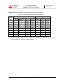
Table 3.6 Wiring configuration
Figure
Input
Output
One feed
Input
Output
Voltage
Voltage
/ Two feed
Transformer
Transformer
3.3 a
208
208
Two
-
-
-
3.3 b
208
208
One
-
-
-
3.3 c
480
208
Two
O
-
-
3.3 d
480
208
One
O
-
-
3.3 e
480
208
One
O
-
O
3.3 f
480
480
Two
O
-
-
3.3 g
480
480
One
O
-
-
3.3 h
480
480
One
O
O
-
3.3 i
600
208
Two
O
-
-
3.3 j
600
208
One
O
-
-
3.3 k
600
600
Two
O
-
-
3.3 l
600
600
One
O
-
-
3.3 m
600
600
One
O
O
-
*MBS: Maintenance Bypass Switch
MITSUBISHI ELECTRIC 2033A SERIES UPS
MBS*
FIGURE 3.2 a
Page Number:
3-11
2033A SERIES UPS
OWNERS / TECHNICAL MANUAL
MITSUBISHI
ELECTRIC
Input/Output Power Terminals (40 kVA, 50 kVA, 75 kVA UPS)
Power Stage
52CS
DPAU
CB 3
LCD
Static Bypass Input
A30 B30 C30
UPS Output
CB 2
CB 1
UPER
A60 B60 C60 N60
BN
BP
(Battery Input)
A10 B10 C10
(Converter AC input)
75kVA:
ALL POWER TERMINALS USE 1/2” (12 MM) DIAMETER BOLTS
40/50kVA:
AC-INPUT, BATTERY-INPUT TERMINALS USE 7/16”(10 MM)
and BYPASS-INPUT, OUTPUT TEMINALS USE 5/16” (8 MM)
DIAMETER BOLTS
MITSUBISHI ELECTRIC 2033A SERIES UPS
MITSUBISHI
ELECTRIC
Page Number:
3-12
2033A SERIES UPS
OWNERS / TECHNICAL MANUAL
FIGURE 3.2 b Input/Output Power Terminals (30 kVA UPS)
Power Stage
52CS
DPAU
CB 3
LCD
Static Bypass Input
A30 B30 C30
CB2
CB 1
UPS Output
UPER
A60 B60 C60 N60
BN BP A10 B10 C10
(Battery (Converter
Input)
AC input)
ALL POWER TERMINALS USE 3/8” (8 MM) DIAMETER BOLTS
MITSUBISHI ELECTRIC 2033A SERIES UPS
2033A SERIES UPS
OWNERS / TECHNICAL MANUAL
MITSUBISHI
ELECTRIC
Page Number:
3-13
FIGURE 3.3 a Wiring configuration for 208V input / 208V output. (Two sources feeding the UPS)
UPS Module (Model # UP2033A-ExxxSU-2)
User supplied
circuit breaker
3 Phase
4 wires
208V / 60Hz
Bypass
Input
A30
B30
C30
N60
Option
3 Phase
3 wires
208V / 60Hz
AC
Input
A10
B10
C10
AC
Output
A60
B60
C60
N60
Ground
BN
BP
Battery Cabinet
Nominal Voltage: DC 360V
Final Voltage: DC 300V
(180cells/string)
MITSUBISHI ELECTRIC 2033A SERIES UPS
3 Phase
4 wires
208V / 60Hz
2033A SERIES UPS
OWNERS / TECHNICAL MANUAL
MITSUBISHI
ELECTRIC
Page Number:
3-14
FIGURE 3.3 b Wiring configuration for 208V input / 208V output. (One sources feeding the UPS)
UPS Module (Model # UP2033A-ExxxSU-2)
Bypass
Input
A30
B30
C30
N60
Option
User supplied
circuit breaker
3 Phase
4 wires
208V / 60Hz
AC
Input
A10
B10
C10
AC
Output
A60
B60
C60
N60
Ground
BN
BP
Battery Cabinet
Nominal Voltage: DC 360V
Final Voltage: DC 300V
(180cells/string)
MITSUBISHI ELECTRIC 2033A SERIES UPS
3 Phase
4 wires
208V / 60Hz
2033A SERIES UPS
OWNERS / TECHNICAL MANUAL
MITSUBISHI
ELECTRIC
Page Number:
3-15
FIGURE 3.3 c Wiring configuration for 480V input / 208V output. (Two sources feeding the UPS)
UPS Module (Model # UP2033A-ExxxSU-2)
User supplied
circuit breaker
3 Phase
4 wires
208V / 60Hz
Bypass
Input
A30
B30
C30
N60
Option
Transformer cabinet
3 Phase
3 wires
480V / 60Hz
H1
H2
H3
X1
X2
X3
X0
AC
Input
A10
B10
C10
AC
Output
A60
B60
C60
N60
Ground
BN
BP
Battery Cabinet
Nominal Voltage: DC 360V
Final Voltage: DC 300V
(180cells/string)
MITSUBISHI ELECTRIC 2033A SERIES UPS
3 Phase
4 wires
208V / 60Hz
2033A SERIES UPS
OWNERS / TECHNICAL MANUAL
MITSUBISHI
ELECTRIC
Page Number:
3-16
FIGURE 3.3 d Wiring configuration for 480V input / 208V output. (One sources feeding the UPS)
UPS Module (Model # UP2033A-ExxxSU-2)
Transformer
cabinet
Bypass
Input
A30
B30
C30
N60
Option
Jumper
A30,B30,C30 To
A10,B10,C10
User supplied
circuit breaker
3 Phase
3 wires
480V / 60Hz
H1
H2
H3
X1
X2
X3
X0
AC
Output
A60
B60
C60
N60
A10
B10
C10
AC
Input
Ground
BN
BP
Battery Cabinet
Nominal Voltage: DC 360V
Final Voltage: DC 300V
(180cells/string)
MITSUBISHI ELECTRIC 2033A SERIES UPS
3 Phase
4 wires
208V / 60Hz
2033A SERIES UPS
OWNERS / TECHNICAL MANUAL
MITSUBISHI
ELECTRIC
Page Number:
3-17
FIGURE 3.3 e Wiring configuration for 480V input / 208V output. (One sources feeding the UPS)
Input Transformer / MBP
Cabinet
SW2
UPS Module (Model # UP2033A-ExxxSU-2)
Bypass
Input
A30
B30
C30
N60
Option
Jumper
A30,B30,C30 To
A10,B10,C10
User supplied
circuit breaker
SW3
AC
Output
3 Phase
4 wires
208V / 60Hz
SW1
H1
H2
H3
3 Phase
3 wires
480V / 60Hz
A10
B10
C10
X1
X2
X3
X0
A60
B60
C60
N60
AC
Input
From
Neutral
N
Ground
BN
BP
Battery Cabinet
Nominal Voltage: DC 360V
Final Voltage: DC 300V
(180cells/string)
MITSUBISHI ELECTRIC 2033A SERIES UPS
2033A SERIES UPS
OWNERS / TECHNICAL MANUAL
MITSUBISHI
ELECTRIC
Page Number:
3-18
FIGURE 3.3 f Wiring configuration for 480V input / 480V output. (Two sources feeding the UPS)
UPS Module (Model # UP2033A-ExxxSU-4)
User supplied
circuit breaker
3 Phase
4 wires
480V / 60Hz
Bypass
Input
A30
B30
C30
N60
Option
Transformer
cabinet
3 Phase
3 wires
480V / 60Hz
H1
H2
H3
X1
X2
X3
X0
AC
Input
A10
B10
C10
AC
Output
A60
B60
C60
N60
Ground
BN
BP
Battery Cabinet
Nominal Voltage: DC 360V
Final Voltage: DC 300V
(180cells/string)
MITSUBISHI ELECTRIC 2033A SERIES UPS
3 Phase
4 wires
480V / 60Hz
2033A SERIES UPS
OWNERS / TECHNICAL MANUAL
MITSUBISHI
ELECTRIC
Page Number:
3-19
FIGURE 3.3 g Wiring configuration for 480V input / 480V output. (One sources feeding the UPS)
UPS Module (Model # UP2033A-ExxxSU-4)
Bypass
Input
A30
B30
C30
N60
Option
User supplied
circuit breaker
3 Phase
4 wires
480V / 60Hz
Transformer
cabinet
H1
H2
H3
X1
X2
X3
X0
AC
Input
A10
B10
C10
AC
Output
A60
B60
C60
N60
Ground
BN
BP
Battery Cabinet
Nominal Voltage: DC 360V
Final Voltage: DC 300V
(180cells/string)
MITSUBISHI ELECTRIC 2033A SERIES UPS
3 Phase
4 wires
480V / 60Hz
2033A SERIES UPS
OWNERS / TECHNICAL MANUAL
MITSUBISHI
ELECTRIC
Page Number:
3-20
FIGURE 3.3 h Wiring configuration for 480V input / 480V output with transformer cabinet. (One sources feeding the UPS)
UPS Module (Model # UP2033A-ExxxSU-2)
Transformer
Cabinet (1/2)
Transformer
Cabinet (2/2)
Bypass
Input
A30
B30
C30
N60
Option
User supplied
circuit breaker
3 Phase
3 wires
480V / 60Hz
Bottom
H1
H2
H3
X1
X2
X3
X0
AC
Input
A10
B10
C10
AC
Output
Jumper
A30,B30,C30 To
A10,B10,C10
A60
B60
C60
Top
X1
X2
X3
H1
H2
H3
H0
3 Phase
4 wires
480V / 60Hz
Output
Ground
Ground
Ground
BN
BP
Battery Cabinet
Nominal Voltage: DC 360V
Final Voltage: DC 300V
(180cells/string)
MITSUBISHI ELECTRIC 2033A SERIES UPS
2033A SERIES UPS
OWNERS / TECHNICAL MANUAL
MITSUBISHI
ELECTRIC
Page Number:
3-21
FIGURE 3.3 i Wiring configuration for 600V input / 208V output. (Two sources feeding the UPS)
UPS Module (Model # UP2033A-ExxxSU-2)
User supplied
circuit breaker
3 Phase
4 wires
208V / 60Hz
Bypass
Input
A30
B30
C30
N60
Option
Transformer cabinet
3 Phase
3 wires
600V / 60Hz
H1
H2
H3
X1
X2
X3
X0
AC
Input
A10
B10
C10
AC
Output
A60
B60
C60
N60
Ground
BN
BP
Battery Cabinet
Nominal Voltage: DC 360V
Final Voltage: DC 300V
(180cells/string)
MITSUBISHI ELECTRIC 2033A SERIES UPS
3 Phase
4 wires
208V / 60Hz
2033A SERIES UPS
OWNERS / TECHNICAL MANUAL
MITSUBISHI
ELECTRIC
Page Number:
3-22
FIGURE 3.3 j Wiring configuration for 600V input / 208V output. (One sources feeding the UPS)
UPS Module (Model # UP2033A-ExxxSU-2)
Transformer
cabinet
Bypass
Input
A30
B30
C30
N60
Option
User supplied
circuit breaker
3 Phase
3 wires
600V / 60Hz
H1
H2
H3
X1
X2
X3
X0
AC
Input
A10
B10
C10
AC
Output
A60
B60
C60
N60
Ground
BN
BP
Battery Cabinet
Nominal Voltage: DC 360V
Final Voltage: DC 300V
(180cells/string)
MITSUBISHI ELECTRIC 2033A SERIES UPS
3 Phase
4 wires
208V / 60Hz
2033A SERIES UPS
OWNERS / TECHNICAL MANUAL
MITSUBISHI
ELECTRIC
Page Number:
3-23
FIGURE 3.3 k Wiring configuration for 600V input / 600V output. (Two sources feeding the UPS)
UPS Module (Model # UP2033A-ExxxSU-6)
User supplied
circuit breaker
3 Phase
4 wires
600V / 60Hz
Bypass
Input
A30
B30
C30
N60
Option
Transformer
cabinet
3 Phase
3 wires
600V / 60Hz
H1
H2
H3
X1
X2
X3
X0
AC
Input
A10
B10
C10
AC
Output
A60
B60
C60
N60
User supplied
circuit breaker
Ground
BN
BP
Battery Cabinet
Nominal Voltage: DC 360V
Final Voltage: DC 300V
(180cells/string)
MITSUBISHI ELECTRIC 2033A SERIES UPS
3 Phase
4 wires
600V / 60Hz
2033A SERIES UPS
OWNERS / TECHNICAL MANUAL
MITSUBISHI
ELECTRIC
Page Number:
3-24
FIGURE 3.3 l Wiring configuration for 600V input / 600V output. (One sources feeding the UPS)
UPS Module (Model # UP2033A-ExxxSU-6)
Bypass
Input
A30
B30
C30
N60
Option
User supplied
circuit breaker
3 Phase
4 wires
600V / 60Hz
Transformer
cabinet
H1
H2
H3
X1
X2
X3
X0
AC
Input
A10
B10
C10
AC
Output
A60
B60
C60
N60
Ground
BN
BP
Battery Cabinet
Nominal Voltage: DC 360V
Final Voltage: DC 300V
(180cells/string)
MITSUBISHI ELECTRIC 2033A SERIES UPS
3 Phase
4 wires
600V / 60Hz
2033A SERIES UPS
OWNERS / TECHNICAL MANUAL
MITSUBISHI
ELECTRIC
Page Number:
3-25
FIGURE 3.3 m Wiring configuration for 600V input / 600V output with transformer cabinet. (One sources feeding the UPS)
UPS Module (Model # UP2033A-ExxxSU-2)
Transformer
Cabinet (1/2)
Transformer
Cabinet (2/2)
Bypass
Input
A30
B30
C30
N60
Option
User supplied
circuit breaker
3 Phase
3 wires
600V / 60Hz
Bottom
H1
H2
H3
X1
X2
X3
X0
AC
Output
AC
Input
A10
B10
C10
A60
B60
C60
Top
X1
X2
X3
H1
H2
H3
H0
3 Phase
4 wires
600V / 60Hz
Ground
Output
Ground
Ground
BN
BP
Battery Cabinet
Nominal Voltage: DC 360V
Final Voltage: DC 300V
(180cells/string)
MITSUBISHI ELECTRIC 2033A SERIES UPS
2033A SERIES UPS
OWNERS / TECHNICAL MANUAL
MITSUBISHI
ELECTRIC
Page Number:
3-26
3.4 Operating Procedures
A) UPS Start-up Procedure
1.
Verify that SW2 (contactor CB3 operator) is in the OFF position.
2.
Close Control Circuit Breaker (CB101).
3.
Verify that the External Bypass input Circuit Breaker(user supplied. Refer to warning 2) is
closed. Place SW2 in the ON position.
4.
Within about ten (10) seconds the AC Input Circuit Contactor (CB1), followed by the Battery
Disconnect Circuit Contactor (CB2), will automatically close.
5.
The audible annunciator will sound and the instruction "PRESS START / STOP KEY" will be
displayed on the LCD panel. ( Figure 3.4)
6.
Press the "Inverter Start" key in the START/STOP menu on the LCD panel. (Figure 3.5)
FIGURE 3.4 START-UP MENU
7.
FIGURE 3.5 INVERTER START/STOP
When the message "LOCAL" is displayed on the LCD panel, the inverter start operation can
only be performed locally at the UPS front panel.
When the message "REMOTE" is
displayed on the LCD pane, the inverter start operation can be started by remote operation
only. Lock-out of one inverter start mode is inherent and cannot be.
8.
If a local inverter start operation is required (at the UPS), select "Local" in "Remote/Local"
function via the Operation menu. Select “LOCAL” mode.
9.
Within five (5) seconds, the Inverter will start-up and begin supplying power to the critical
load.
10. If power is not supplied to the load, follow the instructions on the LCD panel.
B) UPS Shutdown Procedure
1.
If a total UPS shutdown is required, verify that the critical load is OFF.
MITSUBISHI ELECTRIC 2033A SERIES UPS
2033A SERIES UPS
OWNERS / TECHNICAL MANUAL
MITSUBISHI
ELECTRIC
Page Number:
3-27
2.
Select "STOP MENU" from the Operations menu.
3.
Press the "INVERTER STOP" key in the START/STOP menu on the LCD panel. The UPS
will transfer the load to the static bypass line.
4.
When the "LOCAL" is displayed on the LCD panel, the operation can be performed at the
UPS front panel. When the "REMOTE is displayed on the LCD pane, the Inverter can be
stopped by remote operation only. If the inverter stop operation is required locally (at the
UPS), select to "LOCAL" from the
"Remote/Local" selection in the Operations menu.
Select “Local” mode.
5.
Generally, the Inverter alone will be stopped and the Converter will remain energized to
float-charge the batteries.
If stopping the converter is required, open control circuit breaker CB101.
The battery
disconnect contactor (CB2) and the converter input contactor (CB1) will both open
automatically.
WARNING : Verify the load is OFF if the next step is to be performed.
NOTE : Power to the critical load is supplied through the static bypass line.
Power to the critical will be lost after execution of the next step.
The
load will drop.
6.
If turning off all power to critical load is desired, open the Bypass input Circuit
Breaker(MCCB inside the user’s cabinet) manually.
7.
Contactor CB3 will open automatically.
CAUTION : All UPS power terminals are still live. Lethal voltages present.
De-energize all external sources of AC and DC voltages before
handling UPS.
3.5 Internal Maintenance bypass set-up procedure
A)
1.
Transfer of load from inverter to internal maintenance bypass
Stop the inverter by pressing the START/STOP key on the LCD’s Main Menu.
Simultaneously press the tow (2) STOP keys per the instructions. (Note : inverter STOP
function inhibited if bypass and inverter are out of sync.)
MITSUBISHI ELECTRIC 2033A SERIES UPS
2.
Page Number:
3-28
2033A SERIES UPS
OWNERS / TECHNICAL MANUAL
MITSUBISHI
ELECTRIC
Confirm via the flow diagram on the LCD that the load is fed from the UPS’ static bypass
line.
3.
After confirming Step2, rotate cam switch from NORMAL (UPS) to BYPASS
(maintenance bypass).
4.
UPS can now be powered down per instructions on the LCD’s OP. MENU.
5.
Transfer is now complete. Load is fed from external source (Utility or generator).
B)
Transfer of load from internal maintenance bypass to inverter
1.
Confirm SW2 is closed and Static Bypass line is on and energized.
2.
Close CB101.
3.
Confirm via the flow diagram on the LCD that the UPS’s output is fed from the static
bypass line.
4.
After confirming Step2, rotate cam switch from BYPASS (maintenance bypass) to
NORMAL (UPS).
5.
Press inverter START key on LCD to transfer load to inverter.
6.
Transfer is now complete. Load is protected by UPS.
3.6 Maintenance bypass set-up procedure for Input Trans/MBP Combination Cabinet
A)
Transfer of load from inverter to external maintenance bypass
1.
On the UPS LCD, select “Operation Menu”. Select “Stop Menu”.
Press both “Stop” keys simultaneously to turn inverter OFF.
Press “Start/Stop” key.
2.
Confirm with flow diagram on UPS LCD that the load is fed via UPS’ static bypass line. DO
NOT PROCEED IF LOAD IS NOT FED VIA STATIC BYPASS.
3.
After confirming step 2 on MBP, press and hold pushbutton for SLU. While holding
pushbutton rotate key in SLU counterclockwise and remove. Release pushbutton.
4.
Insert key from SLU into Key Interlock for SW2. Rotate key clockwise to unlock SW2.
SW2 on MBP.
5.
On MBP, open SW3. Rotate key in key interlock on SW3 counterclockwise to lock SW3 open.
Remove key. Load is now on utility or generator.
6.
Insert key from SW3 into SLU and rotate clockwise.
7.
On MBP, open SW1. Transfer is complete. The UPS is now isolated from the load.
down UPS per instructions in “Stop Menu” referenced in step (1) above.
Close
Power
For full electrical isolation of dual input feeds to UPS open the External AC Input Circuit Breaker
(user supplied) and Battery Disconnect, if applicable (external to UPS).
MITSUBISHI ELECTRIC 2033A SERIES UPS
MITSUBISHI
ELECTRIC
B)
Page Number:
3-29
2033A SERIES UPS
OWNERS / TECHNICAL MANUAL
Transfer of load from external maintenance bypass to inverter
1.
On MBP, close SW1. If UPS has dual feeds, Verify/Close External AC Input Circuit Breaker
(user supplied) for UPS and Battery Disconnect if applicable.
2.
On UPS LCD, select “Operation Menu”. Select “Start Menu”. Start UPS and Inverter per
instructions.
3.
On UPS LCD, select “Operation Menu”. Select “Stop Menu”.
4.
Confirm with flow diagram on UPS LCD that load is fed via UPS’ static bypass line. DO NOT
PROCEED IF LOAD IS NOT FED VIA STATIC BYPASS.
5.
Press SLU pushbutton and rotate key for SLU counterclockwise and remove.
6.
On MBP, insert key from SLU into key interlock for SW3.
SW3.
7.
On MBP, open SW2. Rotate key counterclockwise to lock SW2 in the open position.
the key from SW2 and insert into SLU and rotate clockwise.
8.
On the UPS LCD, select “Start/Stop Menu”. Select “Start Menu”. Press “Start” key to turn
inverter ON.
Stop Inverter per instructions.
Rotate key clockwise to unlock, close
9.
Confirm with the flow diagram on the LCD that load is fed via UPS’ inverter.
10.
Transfer is now complete.
Load is protected by UPS.
MITSUBISHI ELECTRIC 2033A SERIES UPS
Remove
2033A SERIES UPS
OWNERS / TECHNICAL MANUAL
MITSUBISHI
ELECTRIC
Page Number:
4-1
4.0 RESPONSE TO UPS FAILURE
UPS FAULT
Depress Silence Alarm Key on MAIN menu.
Annunciator Silence
Refer to the list of fault codes for the description of the error.
Recording of Fault
Take necessary action per the guidance on the display.
Primary Action
When faults occur continuously contact the Authorized
Information to Service Center
Mitsubishi Service Representative or call Mitsubishi at
1-800-887-7830.
Note
The error code indicated on the LCD display panel at the time of UPS alarm condition
is very important. In order to reduce repair time, please include this information, along
with the operation status and load status, on all correspondence with Mitsubishi field
service group.
MITSUBISHI ELECTRIC 2033A SERIES UPS
Page Number:
5-1
2033A SERIES UPS
OWNERS / TECHNICAL MANUAL
MITSUBISHI
ELECTRIC
5.0 PARTS REPLACEMENT
Contact Mitsubishi or its Authorized Service Center on all issues regarding the replacement of
parts.
A)
Battery
Battery lifetime may vary according to the frequency of use and the average ambient
operating temperature. Battery end of life is defined as the state of charge resulting in an
ampere-hour capacity less than, or equal to, 80% of nominal capacity. Replace battery if
capacity is within this percentage.
B)
UPS Component Parts
Contact Mitsubishi or its Authorized Service Center for a complete parts replacement
schedule.
Contact
Recommended replacement time interval varies with operating environment.
Mitsubishi
or
its
Authorized
Service
Center
recommendations.
MITSUBISHI ELECTRIC 2033A SERIES UPS
for
application
specific
2033A SERIES UPS
OWNERS / TECHNICAL MANUAL
MITSUBISHI
ELECTRIC
Page Number:
6-1
6.0 FAULT CODES
This section covers the fault codes, their description and required action.
At time of error :
A) Verify and record the occurrence of the alarm. Note details of alarm message on the
LCD display panel.
Contact Mitsubishi Electric Power Products, Inc. at 1-800-887-7830.
B) If a circuit breaker (MCCB) is in the trip state, depress the toggle to reset the breaker
before closing it again.
MITSUBISHI ELECTRIC 2033A SERIES UPS
6-2
Fault Code List
Note 11.
Code
indication
Note 1
Status massage
Contents
Note 2
Note 3
Note 4
Guidance
Buzzer
External
send-out
contact
Failure
lamp
UF003
CONVERTER
ABNORMAL
Preliminary charge impossible
1
[2]
Major
Lit up
UF052
CB1 TRIPPED
Input circuit breaker CB1 has tripped
1
[1]
Minor
Flicker
UF053
CB1 ABNORMAL
Input circuit breaker CB1 abnormal
1
[1]
Minor
Flicker
Converter input overcurrent
1
[1]
Minor
Flicker
Converter control circuit abnormality
1
[1]
Minor
Flicker
Converter IPM abnormal
1
[2]
Major
Lit up
UF056
UF059
UF060
CONVERTER
OVERLOAD
CONVERTER
ABNORMAL
CONVERTER
ABNORMAL
UF102
DC OVERVOLTAGE
Overvoltage of DC voltage
1
[2]
Major
Lit up
UF103
DC UNDERVOLTAGE
Low voltage of DC voltage
1
[2]
Major
Lit up
UF105
SENSOR ABNORMAL
DC voltage sensor circuit abnormality
1
[2]
Major
Lit up
UF106
DC CAPACITANCE
ABNORMAL
Electrolytic capacitor abnormality
1
[2]
Major
Lit up
UF107
CB2 ABNORMAL
1
[2]
Major
Lit up
2
[1]
Minor
Flicker
2
[1]
Minor
Flicker
1
[1]
Minor
Flicker
UF151
UF152
DC VOLTAGE
ABNORMAL
DC VOLTAGE
ABNORMAL
Battery disconnect circuit breaker CB2
abnormal
Does not return to float voltage after power
supply is resumed (24 hours)
Does not return to equalizing voltage after
power supply is resumed
Battery disconnect circuit breaker CB2 has
tripped.
UF153
CB2 TRIPPED
UF154
CB2 ABNORMAL
CB2 turned OFF
1
[1]
Minor
Flicker
UF156
CB2 TRIPPED
(BATTERY
OVERTEMPERATURE)
Battery temperature abnormality (UF157)
lasted a long time (Note 6)
1
[1]
Minor
Note 5
Flicker
2
[1]
2
[1]
1
[1]
Minor
Flicker
2
[1]
Minor
Flicker
1
[2]
Major
Lit up
1
[2]
Major
Lit up
Inverter output overcurrent
1
[2]
Major
Lit up
UF157
UF158
(Note10)
BATTERY
Battery temperature abnormality
OVERTEMPERATURE
BATTERY LIQUID LEVEL
Battery solution level drop (Note 7)
LOW
UF160
SENSOR ABNORMAL
Sensor abnormality of battery circuit
UF161
CB2 TRIPPED (DC
VOLTAGE ABNORMAL)
UF162
BATTERY ABNORMAL
Does not return to float voltage after power
supply is resumed (48 hours) (Note 6)
Battery abnormal detected by battery self
test.
Output overvoltage during inverter power
supply (+ 15%)
Output low voltage during inverter supply (15%)
UF201
UF202
UF203
INVERTER
OVERVOLTAGE
INVERTER
UNDERVOLTAGE
INVERTER
OVERCURRENT
Minor
Note 5
Minor
Note 5
Flicker
Flicker
UF209
52C ABNORMAL
52C not turned ON
1
[2]
Major
Lit up
UF210
52C ABNORMAL
52C not turned OFF
1
[2]
Major
Lit up
UF212
FAN ABNORMAL
Fan power source abnormality during
operation
1
[2]
Major
Lit up
UF213
INVERTER OR
CONVERTER
OVERTEMPERATURE
Overheating of main circuit parts
1
[2]
Major
Lit up
UF214
COOLING FAN
ABNORMAL
Abnormality of cooling fan inside panel
1
[2]
Major
Lit up
UF216
INVERTER ABNORMAL
Inverter IPM abnormal
1
[2]
Major
Lit up
UF255
52C ABNORMAL
52C turned OFF during inverter power
supply
1
[1]
Minor
Flicker
6-3
Note 11.
Code
indication
Note 1
Status massage
Contents
Note 2
Note 3
Note 4
Guidance
Buzzer
External
send-out
contact
Failure
lamp
UF256
OUTPUT VOLTAGE
ABNORMAL
Inverter output voltage fell out of +/- 5%
1
[1]
Minor
Flicker
UF257
52C ABNORMAL
52C not turned OFF when manual transfer
1
[1]
Minor
Flicker
UF258
OVERLOAD
Frequent overload
4
[1]
Minor
Flicker
Control microcomputer abnormality
1
[2]
Major
Lit up
Control microcomputer abnormality
1
[2]
Major
Lit up
Control microcomputer abnormality
1
[2]
Major
Lit up
Control microcomputer abnormality
1
[2]
Major
Lit up
Control circuit abnormality
1
[2]
Major
Lit up
Control power source circuit abnormality
1
[2]
Major
Lit up
Inverter output voltage abnormality before
inverter power supply
1
[2]
Major
Lit up
Battery circuit's fuse burnt
1
[1]
Minor
Flicker
Control circuit abnormality
1
[1]
Minor
Flicker
Control circuit abnormality
1
[1]
Minor
Flicker
Control circuit abnormality
1
[1]
Minor
Flicker
1
[1]
Minor
Flicker
1
[1]
Minor
Flicker
1
[1]
Minor
Flicker
1
[1]
Minor
Flicker
1
[1]
Minor
Flicker
1
[2]
Major
Lit up
1
[2]
Major
Lit up
UF301
UF302
UF303
UF304
UF305
UF306
UF309
UF351
UF352
UF355
(Note10)
UF356
UF357
UF358
UF359
UF360
UF362
UF401
UF402
UPS CONTROL CIRCUIT
ERROR
UPS CONTROL CIRCUIT
ERROR
UPS CONTROL CIRCUIT
ERROR
UPS CONTROL CIRCUIT
ERROR
UPS CONTROL CIRCUIT
ERROR
UPS CONTROL CIRCUIT
ERROR
INVERTER VOLTAGE
ABNORMAL
CONTROL FUSE
BLOWN
SUPPLY OF CONTROL
CIRCUIT ABNORMAL
UPS CONTROL CIRCUIT
ERROR
UPS CONTROL CIRCUIT
ERROR
"INVERTER START "
BUTTON ABNORMAL
"INVERTER STOP "
BUTTON ABNORMAL
"INVERTER SUPPLY"
BUTTON ABNORMAL
"INVERTER START" button is abnormal
(Local)
"INVERTER STOP" button is abnormal
(Local)
"INVERTER SUPPLY" button is abnormal
"BYPASS SUPPLY"
"BYPASS SUPPLY" button is abnormal
BUTTON ABNORMAL
UPS CONTROL CIRCUIT
52S control circuit abnormality (Note 8)
ERROR
52S not turned ON, or 52S turned ON
52S ABNORMAL
without any command
52S not turned OFF, or 52S turned OFF
52S ABNORMAL
without any command
UF451
52S ABNORMAL
52S not turned ON, or 52S turned ON
without any command when manual transfer
1
[1]
Minor
Flicker
UA801
AC INPUT VOLTAGE
OUT OF RANGE
AC input voltage fell out of +/- 18% range
3
[1]
Note 5
Flicker
UA802
AC INPUT FREQUENCY Ac input frequency fell out of converter
OUT OF RANGE
synchronization follow-up range
3
[1]
Note 5
Flicker
Phase rotation is inverted when input
voltage is normal
3
[1]
Note 5
Flicker
CONV switch was turned off.
1
[1]
Note 5
Flicker
Temp. abnormality in room where installed
11
[1]
Overload exceeded 105% (Note 9)
4
[1]
Over
Flicker
Overload exceeded 125% (Note 9)
4
[1]
Over
Flicker
Overload exceeded 150% (Note 9)
4
[1]
Over
Flicker
Momentary over-current during Inverter
power.
4
[1]
Over
Flicker
UA803
UA804
UA805
(Note10)
UA806
UA808
UA809
UA810
AC INPUT PHASE
ROTATION ERROR
CONVERTER
ABNORMAL
AMBIENT
TEMPERATURE
ABNORMAL
INVERTER OVERLOAD
> 100%
INVERTER OVERLOAD
> 125%
INVERTER OVERLOAD
> 150%
OVERLOAD
Flicker
6-4
Note 11.
Code
indication
UA811
UA812
UA813
UA814
UA816
UA817
Note 1
Status massage
BYPASS VOLTAGE OUT
OF RANGE
BYPASS VOLTAGE OUT
OF RANGE
BYPASS PHASE
ROTATION ERROR
BYPASS FREQUENCY
OUT OF RANGE
EXTENDED BYPASS
OPERATION
EMERGENCY STOP
ACTIVATED
Note 2
Note 3
Note 4
Guidance
Buzzer
External
send-out
contact
Failure
lamp
Bypass voltage fell out of +/- 10% range at
manual transfer
5
[1]
Note 5
Flicker
Bypass voltage fell out of +/- 20% range
5
[1]
Note 5
Flicker
5
[1]
Contents
Phase rotation is inverted when bypass
voltage is normal
Bypass frequency fell out of inverter
synchronization follow-up range
Bypass power supply continued for many
hours
Emergency stop applied
5
[1]
Flicker
Minor
Note 5
[1]
13
[2]
Flicker
Flicker
Minor
Flicker
Transfer cannot be permitted because
Bypass voltage abnormal
There is an error with the remote start
switch.
There is an error with the remote stop
switch.
5
[1]
Flicker
12
[1]
Flicker
12
[1]
Flicker
UA821
UPS STOPPED
(TRANSFER INHIBITED - Transfer cannot be permitted because
INVERTER AND BYPASS Bypass voltage abnormal
ASYNCHRONOUS)
5
[1]
Flicker
UA822
GENERATOR
Transfer cannot be permitted because
OPERATION , INHIBITED
Generator operation contact is ON
BYPASS OPERATION
[1]
Flicker
UA824
CB2 OFF
7
[1]
Flicker
UA826
CB101 OFF
8
[1]
Flicker
AC input voltage fell out of - 10% range
3
[1]
Flicker
Emergency bypass switch turned to
<Emergency>
10
[1]
Flicker
5
[1]
Flicker
10
[2]
UA818
UA819
UA820
UA830
UA831
TRANSFER ABNORMAL
REMOTE SWITCH
ON(START)
REMOTE SWITCH
ON(STOP)
AC INPUT
UNDERVOLTAGE
EMERGENCY BYPASS
SWITCH ON
Battery disconnect circuit breaker CB2
turned OFF
Control power source breaker CB101 turned
OFF during inverter operation
UA832
INTERRUPTED
TRANSFER OCCURRED When transfer to the bypass supply, occurs
WHEN TRANSFERRING interrupted transfer.
TO BYPASS SOURCE
UA834
BATTERY DEPLETED
UA835
UPS STOPPED
(TRANSFER INHIBITED - Transfer cannot be permitted because
BYPASS INPUT
Bypass voltage is abnormal
ABNORMAL)
UA836
OVERLOAD
DC voltage dropped below discharge end
during inverter operation
Converter overload
5
Note 5
[1]
Flicker
[1]
Flicker
2033A SERIES UPS
OWNERS / TECHNICAL MANUAL
MITSUBISHI
ELECTRIC
Page Number:
6-5
(Note 1) Numbered guidance:
1:
Contact Mitsubishi.
2:
Verify battery is operating within recommended voltage and temperature ranges.
3:
Verify input power source is properly connected.
4:
Reduce load.
5:
Verify bypass power source is within amplitude and frequency.
6:
Close CB1.
7:
Close CB2.
8:
Close CB101.
9:
Reduce load and restart.
10: Press the reset button.
11: Reduce room temperature to within specified UPS operating limits
12: Verify remote switch is properly connected and/or functional.
13: Place switch in OFF position.
(Note 2)
Audible annunciator: [1] intermittent sound, [2] continuous sound.
(Note 3)
"Major" is defined as major failure. Inverter transferred to the static bypass line;
"Minor" is defined as a minor failure. UPS continues to operate normally, but cause of
alarm must be identified;
“Over" is defined as an overload condition. UPS will transfer to the static bypass line and
may or may not return to the inverter. Return to inverter will occur only if overload
corrects itself and output load is within rating of UPS.
(Note 4)
Indicates one of two possible LED illumination patterns - continuously on (lit) or intermittent
(flicker).
(Note 5)
External send-out possible by option setting.
(Note 6)
Trips the battery breaker CB2.
MITSUBISHI ELECTRIC 2033A SERIES UPS
MITSUBISHI
ELECTRIC
2033A SERIES UPS
OWNERS / TECHNICAL MANUAL
Page Number:
6-6
(Note 7)
For other than sealed-type battery.
(Note 8)
Place UPS Emergency Bypass switch in the BYPASS position. Contact Mitsubishi.
(Note 9)
If the specified time passes, will transfer to the bypass power supply.
(Note 10)
Shows only when corresponding option settings are made.
(Note 11)
Code indication means:
UA ------------- Alarm
UF ------------- Failure
U0 ------------- Converter circuit failure
U1 ------------- DC circuit failure
U2 ------------- Inverter circuit failure
U3 ------------- Control circuit failure
U4 ------------- Bypass system failure
U8 ------------- Alarm
U00 - U49 ------ Major failure
U50 - U99 ------ Minor failure
MITSUBISHI ELECTRIC 2033A SERIES UPS
MITSUBISHI
ELECTRIC
Page Number:
7-1
2033A SERIES UPS
OWNERS / TECHNICAL MANUAL
7.0 WARRANTY & OUT OF WARRANTY SERVICE
The Mitsubishi Electric UPS Division Service Department has many Authorized Service Centers
place strategically throughout the US, Canada and Latin America.
For both in warranty and out
of warranty service, please contact Mitsubishi Electric Power Products, Inc. at (847) 478-2100.
To register your UPS for warranty purposes, please complete the warranty registration form and
fax it to the Mitsubishi Electric UPS Division Service Department fax line shown on the
registration form. (Next page)
For warranty purposes, it is essential that any and all service work that may be required on your
Mitsubishi brand UPS equipment is performed by a Mitsubishi Electric Authorized Service Center.
The use of non-authorized service providers may void your warranty.
Mitsubishi Electric Power Products, Inc
UPS Division Service Department
500 Corporate Woods Parkway,
Vernon Hills, Illinois 60061, USA
Phone: (847) 478-2100
Fax: (847) 478-2290
MITSUBISHI ELECTRIC 2033A SERIES UPS
NOTE: PLEASE READ THE TERMS OF THIS LIMITED WARRANTY CAREFULLY PRIOR TO
INSTALLATION AND START-UP OF YOUR NEW MITSUBISHI UNINTERRUPTIBLE POWER
SUPPLY SYSTEM. FAILURE TO FOLLOW THESE PROCEDURES MAY VOID YOUR LIMITED
WARRANTY!
MITSUBISHI ELECTRIC POWER PRODUCTS, INC.
UNINTERRUPTIBLE POWER SUPPLY SYSTEM
(2033A/2033C/2033D/9700/9800A SERIES)
LIMITED WARRANTY POLICY AND PROCEDURES
1. LIMITED WARRANTY: MITSUBISHI ELECTRIC POWER PRODUCTS, INC. (“MEPPI”) warrants to the original end
user that the 2033A/2033C/2033D/9700/9800A series Uninterruptible Power Supply Unit sold by MEPPI (the “Product”)
shall be free from defects in material and workmanship under normal use and service for a period of twenty four(24) months
from the date of installation or thirty (30) months from the date of shipment of the Product, whichever comes first, the original
end user (the “Warranty Period”). If MEPPI receives notice of any defects during the Warranty Period, MEPPI shall, at its
option, repair or replace any defective parts, subject to the limitations and procedures described below.
A. LIMITATIONS. This Limited Warranty shall cover the Product only if all of the following conditions have been met:
(1) If temporary on-site storage of the Product was required before installation, all prescribed storage requirements as set
forth in MEPPI’s published storage guidelines shall have been strictly followed.
(2) MEPPI’s UPS Divisions Service Department or a MEPPI Authorized Service Organization shall have inspected the
installation site to determine correct application conditions and to perform any required inspections, calibrations and
startup of the Product. Contact MEPPI at the number listed below to schedule startup of the Product.
(3) This limited warranty does not include travel and related costs for Products installed outside the United States. Consult
your local MEPPI representative for terms and conditions.
B. EXCLUSIONS. This Limited Warranty does not cover:
(1) System batteries/battery plant and all other peripheral products and accessories not manufactured by MEPPI (including
components or software) or the installation, operation, maintenance or service of such accessories. These items may
be separately warranted by the manufacturer of the item in question.
(2) Any Product whose serial number has been altered defaced or removed.
(3) Any Product which has been damaged during shipment.
(4) Product defects caused by installation, start-up, wiring, modification, alteration, repair, service or parts replacement
except by MEPPI or an authorized MEPPI service representative. Contact MEPPI at the number below for a list of
authorized service providers in your area.
(5) Product defects caused by inadequate maintenance, misuse, physical abuse of the Product, accident, excessive stress
or operation of the Product under abnormal environmental conditions or contrary to the Product’s operating instructions.
(6) Product defects caused by failure to follow the operational specifications or the handling and operational procedures
prescribed in the Product Owner’s Manual.
(7) Service, repair or replacement of parts made necessary by any cause beyond MEPPI’s control, including, but not limited
to, fire, theft, lightning, acts of God, negligence, accident, excessive physical or electrical stress or operation under
abnormal environmental conditions.
(8) Products which have been decommissioned and/or relocated from the original installation site.
C. ADDITIONAL LIMITATIONS
(1) Parts used for replacements are warranted for the longer of 90 days or the remainder of the original Warranty Period. All
defective Product parts shall be the property of MEPPI upon replacement. MEPPI reserves the right to make any or all
changes to the Products that it may deem necessary without prior notice to customer. Replacement parts may be new
or reconditioned or refurbished.
(2) THIS LIMITED WARRANTY IS EXCLUSIVE, AND NO OTHER WARRANTY WHETHER WRITTEN OR ORAL, IS
EXPRESSED OR IMPLIED. MEPPI SPECIFICALLY DISCLAIMS ANY IMPLIED WARRANTY OF
MERCHANTABILITY AND FITNESS FOR ANY PARTICULAR PURPOSE, WHICH SHALL NOT BE APPLICABLE
UNDER ANY CIRCUMSTANCES WHATSOEVER.
(3) THIS LIMITED WARRANTY SHALL CONSTITUTE THE SOLE AND EXCLUSIVE REMEDY OF ALL PURCHASERS
AND USERS OF THE PRODUCT. UNDER NO CIRCUMSTANCES SHALL MEPPI BE LIABLE FOR DAMAGES,
WHETHER DIRECT, INDIRECT, SPECIAL, INCIDENTAL OR CONSEQUENTIAL BY REASON OF ANY
DEFECTIVE PRODUCTS, BREACH OF THIS LIMITED WARRANTY, BREACH OF CONTRACT, TORT
(INCLUDING NEGLIGENCE OR STRICT LIABILITY) OR OTHERWISE. IN NO EVENT SHALL MEPPI BE LIABLE
FOR ANY AMOUNT IN EXCESS OF THE PURCHASE PRICE PAID FOR ANY PRODUCT FOUND TO BE
DEFECTIVE.
2. PROCEDURES
A. Direct all inquiries to:
MITSUBISHI ELECTRIC POWER PRODUCTS, INC.
Attention: UPS Division Service Department
500 Corporate Woods Parkway
Vernon Hills, Illinois 60061
Phone: (847) 478-2100
Fax:
(847) 478-2290
B. All claims for warranty service shall be submitted to MEPPI at the address listed in 2A above. Claims shall be made in
writing or by telephone or fax subsequently confirmed in writing and will be considered received on the day notice is
actually received by MEPPI.
C. If MEPPI determines that the repair is covered under this Limited Warranty, MEPPI shall repair or replace the defective
part at no charge to the customer. MEPPI shall advise the customer if it determines that the requested repair is not
covered under this Limited Warranty. Upon customer’s request, MEPPI shall perform the repair at the customer’s cost
and expense. Repair charges shall be based on service parts price and the prevailing field service-call charges in effect at
the time of repair. All repair invoices shall be paid within 30 days of invoice date. Past due invoices shall bear interest at the
rate of 1.5% per month, but not in excess of the maximum lawful rate, until paid in full. Customers are responsible for all
costs and expenses, including attorneys’ fees, incurred by MEPPI in collecting any past due invoices.
3. EXTENDED WARRANTY: The original end user may purchase an extension of this limited warranty for up to 36 months
after the expiration of the original limited warranty. Extensions are available on new Product only (not previously placed in
service) located at the site of the original end user; provided the Product has been continuously covered either by the
original warranty or an extended warranty. Contact MEPPI for details prior to the expiration of your initial or extended limited
warranty.
4. MODIFICATIONS: MEPPI may modify the procedures and charges described in this Limited Warranty at any time without
prior notice to customer. No modification, waiver or alteration of any of the provisions of this Limited Warranty by customer
shall be binding upon MEPPI, unless made in writing and signed by a duly authorized officer of MEPPI.
5. GOVERNING LAW: This Limited Warranty shall be subject to and construed solely in accordance with the laws of the
United States of American and the State of Illinois, without regard to its principles of conflicts of law. The parties specifically
disclaim the applicability of the United Nations Convention on the International Sale of Goods, as amended, and the United
Nations Convention on the Limitation Period in the International Sale of Goods, as amended, to this Limited
Warranty or any transaction or dispute arising hereunder.
Page Number:
7-2
2033A SERIES UPS
OWNERS / TECHNICAL MANUAL
MITSUBISHI
ELECTRIC
Mitsubishi Electric Power Products, Inc.
UNINTERRUPTIBLE POWER SUPPLIES
500 Corporate Woods Parkway, Vernon Hills, IL 60061
Phone: (847) 478-2100, Fax: (847) 478-2290
UPS Warranty Registration
__ Register UPS for Warranty
__ Address Change
To validate the Warranty on your UPS this form must be filled out completely by
Customer and returned.
CUSTOMER INFORMATION
Your Name:
Job Title:
Company Name:
Division / Department:
Address:
City:
State:
Zip Code:
Country:
Province:
Business Phone:
Ext:
Fax:
E-Mail:
Internet Address:
@
UPS Model #:
Capacity (kVA):
Start-Up Date:
UPS Serial #:
Authorized Mitsubishi Service Company (if known):
/
/
Signature:
Date:
/
Which ONE of These Best Describes Your Organization’s
Primary Business Classification?
{Energy Producer}
__ Utility
__ Alternate Energy
__ Education/Univ. Service
{Service}
__ Consulting
{Manufacturing Co.}
/
Number of Employees at This Location is:
__ 1 – 19
__ 20 – 49
__ 50 – 99
__ 100 - 249
__ 250 - 499
__ 500 - 999
__1000 or more
__ Engineering
__ OEM
__ Outsourcing
__ Process
__ Financial/Legal/Insurance
{Expectations}
__ Consumer Goods
{Government}
Overall how was Start-Up performed:
__Unsatisfactory
__ Satisfactory
__ Exceeded
__ Electronics
__ Military
Would you like to receive future product updates and
__ Power Quality Equipment
__ Municipals
news?
__ Commercial Business
__ Federal/State/Local
__ Electrical Contractor
__ Communications
__ Healthcare
__ Distributors/Reps
__ Internet
__ Other __________________
__Yes
__ No
After Start-Up has been done Fax completed Form to:
(847) 478-2290
MITSUBISHI ELECTRIC 2033A SERIES UPS