1
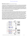
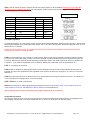
DCC
Not for DC, Analog
The PSX-1,2,3,4 Series (Rev:J, 5/11)
Intelligent, DCC, Solid State Circuit Breakers with
Integrated Block Detection and Feed Back
Quick Start: see Pg-13, Test Before Installing, All Programming is Optional!
Designed by Larry Maier
The PSX series includes 4, DCC Power District
Circuit Breakers that incorporate a solid state
design, block detection and network feedback.
PSX-1: 1 Block Control
PSX-2: 2 Block Control
PSX-3: 3 Block Control
PSX-4: 4 Block Control
Developed by DCC Specialties
US Patent 7,810,435
There are (4) versions of the new PSX-AR Series:
Integrated DCC Circuit Breaker, Auto-Reverser and Stationery Decoder
(1) PSX-AR, w/ integrated Stall Motor Decoder
(2) PSX-ARFB, same as above has added network FeedBack
(3) PSX-ARSC, w/ integrated Snap Coil Decoder
(4) PSX-ARSCFB, same as above has added network FeedBack.
The Power Shield X series is a product of years of research into problems
dealing with false overload that cause premature shut down of DCC Boosters and
other Circuit Breakers. These false overloads are caused by large capacitors used
in sound systems decoders or lighted passenger cars. The overload appears as a
short circuit until the capacitors are charged. The logic on the new Power Shield X
Series determines if the load is a true short or just an overload due to discharged
capacitor.
Versions Available:
PSX-1 One Output, PSX-2 Two Outputs, PSX-3 Three Outputs, PSX-4 Four Outputs:
All Solid State Operation: Fast, solid state design with reliable quiet
action….no clicks or sparks.
Adaptive Load Reset: Electronically determines if the overload is a real short or due to excess
capacitance in sound decoders or lighted passenger cars.
Boost for Low Power Systems: Some low power DCC Systems boosters need a boost when resetting.
Adding this jumper helps reset low power output systems.
Auto Stop with CV Reset: A photocell input can detect a train in the reverse section and turn off power. A DCC
command can then restore the power.
Block Detection: Either a photo cell or current can be used to detect a train in a block. The photocell
can turn off the block. A DCC command can then restore the power.
Over Voltage Protection: If there is an over voltage on the track caused by a DCC System
failure or other power inputs the PSX will shut down and protect decoders
Wide Range of Current Trip Setting: The currents can be adjusted over a range of 1.27 to 17.8 amps.
Values can be set either with CV settings or Jumpers.
Very Low Voltage Drop: Breaker On resistance is less than 0.060 ohms, so the PSX has a low voltage
drop even at high currents. Much better than detectors that use a diode voltage drop.
Manual or Automatic Reset: Automatic reset of the breaker after 2 seconds. A switch can be used for a
manual reset.
Power On/Off by DCC: Turn on/off output track power with your DCC Throttle!
Outputs for LED Indicators: LEDs can be added to monitor the input/output power and the status.
System Reset: CV63=42 sets all CVs to original factory values.
Output for Audio Alert: An audible sounder can be added to the card to alert if there is a short.
Network FeedBack: To Digitax Loco Net, NCE Cab Bus and Lens XpressNet for Shorted and Occupancy.
No Power Supply Needed: Board size: is 4.75 by 2.25 inches
Flash Programmable: Micro Processor can accept updated software if needed.
Note: The PSX Circuit Bds are scribed and milled so you can separate into individual units if needed.
Note: The PSX-1 operates by opening one side of the two inputs leads when an overload is sensed. If you have a situation
where both sides of the input line need to be opened on an overload, use the PSX-AR auto reverser instead of the PSX-1.
The PSX-1 opens the path from J1-4 to J2-2 when the breaker senses an over load. Additional power to the PSX-2, 3, & 4
is connected by daisy chaining from J1, 1 and 2 to the next PSX J1, 3 and 4.
DCC Specialties, 57 River Rd, Suite 1023, Essex Jct., VT. 05452 800-671-0641, [email protected] www.dccspecialties.com
1 of 10
*Instructions by Don Fiehmann
Why Divide my Layout? (Courtesy of Kalmbach Publications)
Though DCC offers a more realistic type of train control – being able to run multiple locomotives independently
on the same track – the electricity running through the rails of your layout still needs to be properly managed
and distributed. Since one of the big selling points of DCC is that you don’t need to divide your layout into
individual electrical blocks for independent train control, you’re probably asking yourself, “why should I do it?”
In addition to minimizing operating disruptions, power districts are also a key to DCC power regulation. If you’re
running a lot of trains, you’ll need to make sure your DCC system can supply all your power needs efficiently
and safely. Adding power districts to your layout can help with that. By separating your layout into districts, you
divide the total track power available into smaller, more manageable units.
How do I Determine Power Districts?
There are really two types of power districts: those that are circuit-breaker protected zones on the layout and
those that have their own independent Booster (also breaker protected). Probably the best way to determine
where to place power districts is to take a look at the expected current draw, (Traffic), for each operating
location on the layout. For example, a busy yard might have two switchers, one or more trains on the arrival
and departure tracks, another train or two passing the yard on the main, and maybe a peddler working nearby
local industries. If some or all of these trains have more than one locomotive, you could have 10 to 15
current-drawing units all competing for power in a fairly small area. Even assuming that the locomotives have
efficient motors, this type of load may be heavy enough to slow down a DCC system running on a common 5A
booster. Generally, our experience has shown that in HO if you have for a 12-14 awg buss and 20 awg
feeders, that a 5 Amp system can support up to 10 0perators. Many users overestimate the amount of Booster
power needed. Try using the PSX Series first, then if your trains start to slow down you may need to add extra
Booster to support the concentration of trains in this location. By dividing a layout into power districts in this
manner, and using a combination of boosters and circuit breakers, you can make the most efficient use of
available power on any mid-size or large-size layout.
DCC Specialties, 57 River Rd, Suite 1023, Essex Jct., VT. 05452 800-671-0641, [email protected] www.dccspecialties.com
2 of 10
Power Shield X-1, 2, 3, 4 Wiring:
Wire to the Power Shield should be heavy enough to carry the current. Size of wire depends on your scale. Too
much resistance in the wire or rails can result in faulty short sensing. At a minimum, use 18 awg for N, 14 awg for
HO and S, 12 awg for O and G.
N o t e: T he s m a l l b l ac k s cr ew t er m i n al s s h o w n i n pi ct ur e ar e o p ti o n al a c c es s or i e s a va i l a bl e fr om yo u r d ea l er . T h e
l ar g e gr e e n i n pu t / o u t p ut t er m i n al s c om e w i t h u n i t s . G e n er a l l y t h e sm al l ter m i n al s ar e n o t n ee d e d as m os t o f t he s e ar e
o ne ti m e c o n ne c ti o n s a n d ar e ea s i l y s ol d er e d t o t h e b d . U s e a sm a l l i r o n ( 20 W - 4 0W ) f or s o l d er i n g t o t h e b d .
D7
Connector Description:
J1 Input Power Connector
J1-1
Connections for Daisy
J1-2
Chaining to next PSX
J1-3
DCC Input 2
J1-4
DCC Input 1
J2 Output Power Connector
J2-1
DCC Output 2
J2-2
DCC Output 1
J7 Auto/Manual Reset and Weak System Boost
J7-1 to J7-2 Open: Auto Reset
J7-1 to J7-2 Jumpered: Manual Reset (open to reset)
J7-3 to J7-4 Enable Weak System Boost
J10 DCC Power In: Indicator (Remote)
J10-1 + DCC Power In, LED Remote
J10-2 - DCC Power In, LED Remote
J11 Track Power On: Indicator (Remote)
J11-1 + Track On LED Remote
J11-2 -Track On LED Remote
J3 Program Jumper
LEDS: D12 Input Power On, D6 Status/Shorted, D7 Output On
J3-1 Connection 1-2 for Programming
J3-2
J3-3 Connection 2-3 for Operations
Trip Current by Jumpers
J4 Block Occupancy
J4-1 and J4-2 Photo Sensor Input
J4-3 + Block Occupied Output (Network Feedback)
J4-4 - Block Occupied Output (Network Feedback)
J4-5 + Block Shorted Output (Network Feedback)
J4-6 - Block Shorted Output (Network Feedback)
J5 Status Outputs (Remote)
J5-1 + status LED Remote (Output Shorted)
J5-2 - status LED Remote (Output Shorted)
J5-3 + Power ON (Network Feedback)
J5-4 - Power ON (Network Feedback)
J6 Trip Current Settings by Jumpers
J6-1-4 See Table to the right and also CV49 and Pg-7.
LED Wiring
DCC Specialties, 57 River Rd, Suite 1023, Essex Jct., VT. 05452 800-671-0641, [email protected] www.dccspecialties.com
3 of 10
Wiring Connections:
J1 – DCC power input connections from the booster. It can be branched out to allow multiple connections to
other breakers or reversers. The Power Link makes it easier to connect to another breaker or reverser. See
the diagram on previous page.
J2 –Circuit Breaker output to the track.
J3 –Is the programming jumper. J3-2 to J3-3 is the normal operating configuration. J3-1 to J3-2, when
connected with power on sets the breaker to enter the programming mode. See special instructions for
Digitrax, Pg-5.
J4-1 and J4-2 are the inputs for the photocell detector used for the stopping function. Note: Be sure there is
sufficient light above the cell to trigger the circuit. The photocell sensitivity is calibrated each time it is armed.
Silonex, NSL-6112
J4-3 (+) and J4-4 (-) are open if the block is not occupied and are connected together (up to 5 mA) if the
block is occupied. This is an opto-isolated output switch and provides no power.
J4-5 (+) and J4-6 (-) are connected together (up to 5 mA) when the breaker has detected a short circuit
and open with no short. This is an opto-isolated output switch and provides no power.
J5-1 (+) and J5-2 (–) are for a remote status LED. The LED is connected directly to the terminals. No resistor
is required. Off means normal– Solid on means a short circuit.
J5-3 and J5-4 are for network power status reporting.
J6 – Sets the current trip level. When CV49=00 (default) the trip current is 3.81 amperes if no jumpers are
installed. If J6-2 is connected to J6-1 and J6-4 to J6-3 is open, then the current trip is 1.27 amperes. If J6-4
is connected to J6-3 and J6-2 to J6-1 is open, then the current trip is 6.35 amperes. If J6-4 is connected to J6-3
and J6-2 is connected to J6-1, then the current trip is 8.89 amperes.
J7-1 and J7-2 are the auto/manual reset input. If the connections are open, the breaker will automatically
try to reset every two seconds. If the terminals are connected together (like a SPST toggle switch or a N/C
push button switch), then the breaker will remain off after a short until the connection from J7-1 to J7-2 is
momentarily opened.
J7-4 to J7-3 is the Weak System Boost enable jumper. When the jumper is installed, the breaker will use a
turn on algorithm that is designed to assist weak system boosters in starting high inrush current loads. It
will also help low power boosters such as the Digitrax Zephyr and the NCE Power Cab start difficult loads.
When CV53 is zero, the jumper will enable/disable this function. If CV53 is a nonzero value, then the Weak
System Boost function is enabled regardless of the presence or absence of a jumper. On Digitrax systems,
setting OPSW #18 to “CLOSED” will extend the short circuit shutdown to 0.5 seconds. This will help prevent
the booster from shutting down during a short circuit.
J10-1 (+) and J10-2 (-) are for a remote indicator showing DCC power is available to the breaker.
J11-1 (+) and J1 1-2 (-) are for a remote indicator showing that the track outputs are on (or off).
DCC Specialties, 57 River Rd, Suite 1023, Essex Jct., VT. 05452 800-671-0641, [email protected] www.dccspecialties.com
4of 10
Setting Addresses and Programming CV’s: Optional/Not Required!
Programming Steps:
The easiest way to program the PowerShieldX is on-the-bench. Connect pins J 1-4 and J 1-3 to the output of your DCC system.
There is a small red LED on the Power Shield that will blink each time a command is accepted. There is also an LED near the
power input and one near the power output used to indicate power status, After programming, return the program jumper back
to the RUN position. If you make a mistake, don’t worry, just go back and program the CV to the desired value. If you are
hopelessly lost, set CV63 to 42 and you can start over again with factory default values.
(1) Do Not Use Program Track!
(2) The PSX’s addresses are SET by moving the program jumper as described below and issuing
Accessory Commands……like operating an accesory by using your DCC Throttle, see also, Pg-10
The Table to the right shows how
the DCC Manufactures identify
the Normal (Clear) and/or
the Thrown Route to operate
accessories.
System
Digitrax
Lenz
MRC
NCE
Norma l(Clear)
c or Closed
Thrown
t or Thrown
+
-
ON
Normal/ON/ 1
OFF
Reverse/OFF/ 2
(3) Configuration CV’s are Programmed in Ops Mode, “on the main”, also by moving the programming
jumper, see Pg 7, use any non-loco address, except defaults, to initiate Ops Mode.
(4) It is important to remember that Addresses are Set and CV’s are Programmed!
Special Programming Instructions:
Specific DCC Systems need to follow specific programming sequences to reliably program the PSX’s , see Pg-10
NCE and MRC: Do not use the Accessory Programming Mode, only use Ops Mode for CV’s see Pg-10
Digitrax: See also Pg-10
Digitrax users should review the settings of the Digitrax, DCS-100/200 prior to programming a PSX. It is important that the
DCS-100/200 has the Switching (Accessory) Control enabled otherwise it will not operate Stationery Decoders or
Accessories like the PSX’s. Caution, the Digitrax Command Station sends out up to eight accessory addresses every time
you use your throttle to turn track power on and/or you reboot the system and have track power set for auto turn on. If you
connect the PSX to the Digitrax system with the PSX’s jumpers set to the programming mode, these eight addresses will
be programmed. It is recommended for Digitrax that the Setting of Addresses and Programming of CV’s be done at the
same time to avoid the accidental Setting of Addresses as described above. See Pg-10.
One Solution:
Turn on the command station and wait a minute before connecting the PSX’s so that it will not see these addresses.
Better solution:
Follow the directions above for setting the PSX’s to the programming mode by moving the jumper and then turn on the
Digitrax system. The eight addresses will be stored. Select and use OPS mode programming to set CV63 to 0, which resets
to default settings, and the PSX’s is ready to program normally. This does mean that you want to be careful if you have
already programmed some addresses. These can be over-written by the Digitrax system. Your best bet is to keep a list of
the address set in each, when you want to add addresses, you will have to set CV63 to 0 and then re-program the original
addresses before adding the new ones.
Lenz: See also Pg-10.
The Lenz system sends repeat accessory commands as long as you hold down the 1 or 4 command key. This ensures that the
accessory decoder sees the message, but can result in the same address stored multiple times while programming the PSX’s.
The solution is simple. Hold the 1 or 4 key down for only a short time. Once you see D10 flash indicating an address has been
stored, release the control key. If you see multiple flashes, you have stored the same address more than once. Since the
PSX’s will flash D10 each time you send it an accessory address, you can easily get a feel for the timing involved. In the
normal operating mode (not programming mode), select an accessory address that has not been programmed into the PSX’s.
Send an accessory command to this address and hold down the 1 or 4 control key. D10 will flash each time the command
station repeats the accessory address. This will give you a feel of how long to hold the control key while you are programming
multiple address.
DCC Specialties, 57 River Rd, Suite 1023, Essex Jct., VT. 05452 800-671-0641, [email protected] www.dccspecialties.com
Page 5 of 10
Setting Addresses and Programming CV’s: Optional/Not Required!
There are Two (2) Accessory Addresses:
(1) The First accessory address lets you turn the output track power from the Power Shield on and off. (Default address 2042)
(2) The Second address is used to arm the photocell circuit. When the light level drops, due to a train covering the photocell, the
power will turn off. Power can be turned back on (or off) under DCC control. The second address (2043 default) arms (when the
command is “on”) the photo detector to turn the output off when the light level drops. This is designed to allow you to stop a train
on a hidden staging track by arming the photo detector and then the reverser will turn off power to the section when the train
covers the photo detector. Once the photo detector has tripped, it will not turn off track power until it is armed again with this
accessory address command.
Setting the Two Accessory Addresses:
Addresses are set by moving jumper, J3 to positions 1-2 for the program mode with power off. Turn power on and the next
accessory command issued by the DCC system will be stored as the first address (track on/off). By default, the unit will store
the next address for the second address. Once the address is entered you can use either the on (clear or +) or the off (throw or -)
function. Thus, you can have two sequential addresses starting at any desired address, or you can have two random
addresses. Remember to power off and put the program jumper back to 2-3, unless you are going to program CV settings. Note:
When changing from run to program mode, wait about 1 minute before turning power back on to the PSX.
Reference Chart for the Two Accessory Commands
Function
Arm Output for Photo Cell
Track Power On/Off
Default Address
2043
2042
Your New Address
?
?
Programming CV’s & Values: Optional
Programming steps: Note: The Program Track is Not Used!
The easiest way to program the Power Shield is on-the-bench Connect pins J1 -4 and J1 -3 to the output of you DCC system.
There is a small red LED on the Power Shield that will blink each time a command is accepted. There is also an LED near the
power input and one near the power output used to indicate power status. If you make a mistake, don’t worry, just go back and
program the CV to the desired value. If you are hopelessly lost, set CV63 to 42 and you can start over again with factory default
values.
Programming the CV values is done using the Programming-on-the-Main (POM) function. With power off, put the programming
jumper on pins 1-2, then turn power back on. Then go into the Program-on-the-main mode. You will need to setup a “fake” loco
address in order to get to the CV setting operation. Put in any address. (Not an address that is in use on the layout.) Hit enter,
then you can start entering the CV numbers followed by the values. When done, turn power off and replace the program jumper
to pins 2-3. See Sequential instructions Pg-10.
CV Settings: Optional
Timing Settings:
Note: there are no jumpers or CVs for setting time delays. The unit uses its own timing algorithm to figure out how to turn on a load.
It differentiates between a short and a surge load, and operates accordingly. It will also recognize a difficult starting load and
try to help the booster get it operating without tripping the booster’s internal shutdown.
DCC Specialties, 57 River Rd, Suite 1023, Essex Jct., VT. 05452 800-671-0641, [email protected] www.dccspecialties.com
Page 6 of 10
CV49 – sets the current trip value. If CV49=0, then the Trip Current jumpers on J6 are enabled. Remember to use either the
Jumpers or the CV settings, not both! The following trip currents can be set by programming:
Trip Current Jumpers
CV49 Value Trip Current (Amps)
3.81 or as Per Jumpers Chart >
00
01
1.27
02
2.54
03
3.81
04
5.08
05
6.35
06
7.62
07
8.89
Continued
CV Value Trip Current
08
10.2
09
11.4
10
12.7
11
14.0
12
15.2
13
16.5
14
17.8
15
19.1
Low Power Systems:
For the Digitrax Zephyr, 01 or 02 (maybe) are OK. The NCE Power Cab and Bachmann EZ should use a value of 01. Both systems
benefit by the activation of the weak system boost jumper, see CV 53. Most 5 amp boosters should be happy with 03 or 04. The
default current is 3.81Amps
Caution continuous operations at a value higher than CV49=08, (10.2 amps) without the addition of heat sinks to the output
transistors may overheat or damage the PSX’s!
.
CV50 is the block detection source selection. CV50=0 selects block current as the parameter to activate the Block Occupied
(J4-3 and J4-4) output. (See CV54.) CV50=1 will use the photocell to activate the Block Occupied output when the phot cell
is covered. Note that the photocell is self-calibrating and will adjust itself to the ambient light level at the time that the unit
is turned on. If you need extra photocells, they are made by Silonex part number NSL-6112.The CV50 default is 0.
CV51 is not used by the consumer.
CV53 enables or disables the Weak System boost. CV53=0 disables the boost unless the Weak System Boost jumper is
installed. Any other value enables the boost regardless of the presence or absence of a jumper on J7-3 and J7-4. The CV53
default is 0.
CV54 sets current level at which the detector turns on to indicate the block is occupied. Values from 0 to 212. This allows you
to set a level above the leakage current on track to minimize.
CV55 –CV62 are not used at present time.
CV63 allows control of the address programming point (same as on the Hare). Setting a value of 42 to CV63 will cause the
circuit breaker to set all CVs and addresses to factory defaults. The CV63 default is 0.
After setting the CVs turn power off and put the program jumper back to run position.
Audible Short Indication
The two holes inside the circle on the top of the board are for use with an audible short indicating device. It is designed for use
with a Digikey part 458-1005. The unit is installed with the (+) terminal in the square hole. See next page.
DCC Specialties, 57 River Rd, Suite 1023, Essex Jct., VT. 05452 800-671-0641, [email protected] www.dccspecialties.com
Page 7 of 10
User Guidelines:
Power Shields are designed so all input/output connections
are made to the screw terminals. Use up to 12 AWG wire. If
you are using heavier buss wire, then solder a short length
of 12 AWG wire to your heavier buss. If your Power Sections
and Reverse blocks are greater than 10 Ft. long be sure to
have at least 2 sets of track feeders for that section.
Insufficient feeders will cause a voltage drop.
When setting up gaps for power sections, we recommended
that the gaps be staggered about1/8”. Perfectly aligned
gaps may reduce the current needed for PSX’s to reverse
properly.
Test your PSX installation prior to running a train as follows.
Observe that your DCC booster is not shorted. Use a suitable
metal object to short the track.
If you short the output simulating a track short, the status
LED D6 should come on and D7 near the output should be off.
If you are using both Power Shield X Breakers and Reversers on a
layout, and the locomotives hesitate when crossing a reverse gap,
then increase the Trip Current on the Power ShieldX Breakers to
the next level or until the PSX-AR operates correctly
Feed Back:
Interfacing to Digitax Loco Net, NCE Cab Bus and Lens XpressNet:
The PSX’s have optional outputs that allow you to convey the of the occupancy and the short circuit status to your; NCE Cab Bus, your Lenz
XpressNet, or your Digitrax Loconet. These connections are made using hardware available from the respective system manufacturers. The
diagrams below show you these connections. Follow your manufacturers directions for use of the data.
Mounting the PSX’s
(1)The PSX’s can be mounted using # 4 screws. Spacers or non-metal washers can also be used to
provide clearance. There are four possible mounting holes, one in each corner
(2) The Screw Terminals are available from your dealer.
(3) The Alarm is Digikey, 458-1005, also try your dealer.
(4) One heat sinks, not shown, Digikey 294-1085, may be needed, for each group of (2) output Transistors. Also, we
recommend Digikey, BER158, double-sided thermal tape (10" x 10" sheet, cut into strips) to attach the heat sink to
the (2) large black output transistors. Photocells not shown, Silonex part number NSL-6112
DCC Specialties, 57 River Rd, Suite 1023, Essex Jct., VT. 05452 800-671-0641, [email protected] www.dccspecialties.com
Page 8 of 10
Quick Start
(A)
All connections involve 2 Inputs from the DCC Booster or the main
line buss and 2 Outputs to the isolated track block!
(B) PSX 1,2,3,4 are ready to operate without programmable options!
(C) Not compatible with Analog Address (00).
(D) Test first before connecting to layout, see User Guidelines, Pg-8.
DCC
Booster
J1-4
J1-3
J2-2
Rail 1
J2-1
Rail 2
PSX-1
Before wiring please check that the program jumper is on pins 2-3 of J3. (Pin 1 is nearest the center of
the card.) See below.
Also when wiring more than one PSX for multiple power districts insure that all input/output polarities are the
same. The illustration above shows the polarity and matching connector pin #’s. For Common Rail wiring
the J2-1 output (Lower) is common and not needed. Both J1 inputs are still required.
Be sure to connect the two wires from the booster to the INPUT and the two wires to the track section to the
OUTPUT connections. If you connect the DCC Buss Power to the PSX’s outputs you will damage the PSX!
When power is applied the red LED, D12 near the input and D7 near the output should be on. If the status LED
D6 near the program jumper is on solid, you may have a short between the two wires from the output or in the
track section.
If you short the output simulating a track short, the status LED D6 should come on and D7 near the output
should be off. See page XXX for more complete testing.
N o t e: T he s m a l l b l ac k s cr ew t er m i n al s s h o w n i n pi ct ur e ar e o p ti o n al a c c es s or i e s a va i l a bl e fr om
yo ur de a l er . T h e l ar g e gr ee n i n p ut / o ut p u t t er m i n al s c om e w i t h u n i t s . G e n er al l y t h e sm al l
ter m i na l s ar e n o t n ee d e d a s m o st o f t h es e ar e o ne - ti m e c o n n ec t i o n s a n d ar e e a si l y s o l d er e d t o t he
b d. U se a sm al l i r o n ( 2 0W -4 0 W ) f or s ol d er i n g t o t h e b d .
D7
DCC Specialties, 57 River Rd, Suite 1023, Essex Jct., VT. 05452 800-671-0641, [email protected] www.dccspecialties.com
9 of 10
Sequential Programming Instruction for Setting the Address and Programming CV’s
Digitrax: Using the DT-400/402
Setting PSX Addresses:
1. Disconnect PSX from DCC power
2. Move PSX Jumper to Program Position
3. Turn DCC power on “PWR”+ “ Y+”
4. After 30 seconds, reconnect DCC power Program CV's at this time (see below)
First, In CV 63, enter a value of 42 to reset. Then set any other CV's needed. Do not
Move Programming jumper or turn off power. .Exit program mode and go to step
5.
5. Press “SWCH” key to enter Switch Mode
6. Select the switch number to be set using the keypad or RH knob.
7. Press either the “OPTN” or “CLOC” key to set address.
8. Repeat steps 6 and 7 until all addresses set.
9. Press “EXIT” key to return to LOCO mode.
10. Turn DCC power off “PWR” “ N –“.
11. Move PSX Jumper to Run Position
12. Turn track power on. Test the switch address setting by using the
“SWCH” key and switch addresses.
13. Turn power off and put the program jumper into the Run position.
14. Turn DCC power on. Test the PSX using the switch commands.
Programming PSX CVs: Do Setting Addresses First, See Above
1. Disconnect PSX from DCC power.
2. Move PSX Jumper to Program Position
3. Turn DCC power on “PWR” “ Y+”
4. After a few seconds, connect DCC power to the PSX
5. Select an unused locomotive number with the keypad or RH knob.
6. Press “PROG “ key until you get from Pg to Po
7. Use LH throttle to set, dial the CV # and the RH throttle for the CV value.
8. Press, “ENTER”
9. Repeat steps 7 & 8 until all the CV values are set.
10. Press “EXIT”
Lenz: Using the LH100:
Setting PSX1’s Addresses:
1. Turn DCC power off.
2. Move PSX-AR Jumper to Program Position
3. Turn DCC power on
4. Press “F5" key to select “SW” mode.
5. Enter the switch number to be set using the keypad, then press ENTER.
6. Press either the “+” or “ – ” key to set the address. Let LED blink once.
7. To enter another address press the “CI” key.
8. Repeat steps 5-7 until all addresses are set.
9. Press “ESC” key to return to normal.
10. Turn DCC power off.
11. Move PSX-AR Jumper to Run Position
12. Turn track power on.
13. Test the switch address setting using “SW” mode and the new switch
address(es).
Programming PSX1’s CVs:
1. Turn DCC power off.
2. Move PSX-AR Jumper to Program Position
3. Turn DCC power on.
4. Select a locomotive number with the keypad that
is unused on your layout.
5. Press the “F” keys and the “+” or “– ” key to select “POM” mode then hit “Enter”.
6. Press “+” or “–” until “CV” is displayed then press “Enter”.
7. Key in the desired CV number then press “Enter”
8. Enter the CV value to change, then press “Enter”.
9. The display will show the CV number and value to be programmed.
10. Hit "Enter" to program the CV, note the LED on
the PSX-AR flashes when the key is released
11. Press "Esc" key to return to Step 7) or press "Esc" three times to exit CV
programming
12. Turn power off and put the Program jumper into the Run position.
13. Turn DCC power on. Test the PSX-AR using the switch commands.
NCE: Using the Pro Cab or Power Cab
Setting PSX1’s Addresses:
1. Turn DCC Power off.
2. Move PSX-AR Jumper to Program Position.
3. Turn DCC Power on.
4. Press SELECT ACCY.
5. Then use the keypad to enter the new switch number.
6. Press ENTER then press either 1 or 2 to set the address.
7. Repeat steps 4 thru 6 until all of the switch addresses are set.
8. Turn DCC Power off.
9. Move PSX-AR Jumper to Run Position.
10. Turn DCC Power on.
Test the switch setting using the SELECT ACCY key.
ProgrammingPSX1’sCVs:
1. Turn DCC Power off.
2. Move PSX-AR Jumper to Program Position.
3. Turn DCC Power on.
4. Use SELECT LOCO to address an unused locomotive number.
5. Press PROG/ESC key to enter PROGRAM ON MAIN mode.
6. Key ENTER to select any unused locomotive number, then ENTER again.
7. Key 2 to enter PROG CV NUM.
8. Enter CV number then ENTER.
9. Enter value to be stored then ENTER.
10. Repeat steps 8 and 9 until finished.
11. Press PROG/ESC to return to normal operation.
12. Turn power off, put the PSX-AR Program Jumper into the Run position.
13. Turn power on.
Test the PSX-AR using the SELECT ACCY key.
MRC: Using the Prodigy Advance Cab:
Setting PSX1’s Addresses:
1. Turn DCC Power off.
2. Move PSX-AR Jumper to Program Position.
3. Turn DCC Power on.
4. Press ACCY key.
5. Then use the keypad to enter the new switch number.
6. Press ENTER then press either 1 or 2 to set the address.
7. Repeat steps 4 thru 6 until all of the CV value are set.
8. Turn DCC Power off.
9. Move PSX-AR Jumper to Run Position.
10. Turn DCC Power on.
Test the switch setting using the ACCY key.
Programming PSX1’s CVs:
1. Turn DCC Power off.
2. Move PSX-AR Jumper to Program Position.
3. Turn DCC Power on.
4. Press LOCO to address an key in an unused locomotive number.
5. Press PROG key to enter PROG MAIN TRACK mode, then press ENTER.
6. Continue to press ENTER until CV# is in the display.
7. Enter the CV number then ENTER.
8. Enter the value to be stored in the CV then ENTER.
9. Repeat steps 8 and 9 until finished.
10. Press ENTER to return to normal operation.
11. Turn power off and put the PSX-AR Program Jumper into the Run
position.
12. Turn DCC power on.
Test the PSX-AR using the ACCY key.
DCC Specialties, 57 River Rd, Suite 1023, Essex Jct., VT. 05452 800-671-0641, [email protected] www.dccspecialties.com
10 of 10