1
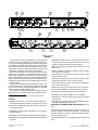
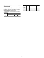
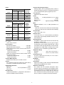
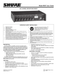
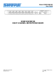
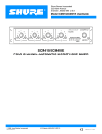
Shure Brothers Incorporated
222 Hartrey Avenue
Evanston IL 60202-3696 U.S.A.
Model FP410 User Guide
ÁÁÁÁ
ÁÁÁÁÁÁÁÁÁÁÁÁÁÁÁÁÁÁÁÁÁÁÁ
ÁÁÁÁÁÁÁÁÁÁÁ
Á
ÁÁÁ
Á
ÁÁÁ
Á
Á
Á
Á
Á
ÁÁÁÁÁÁÁÁ
Á
Á
ÁÁ
ÁÁ
Á
Á
Á
Á
Á
Á
Á
ÁÁ
Á
Á
ÁÁ
Á
Á
ÁÁ
Á
Á
Á
ÁÁ
Á
Á
ÁÁ
Á
Á
ÁÁÁ
Á
ÁÁÁÁÁÁÁÁÁÁÁÁÁÁÁÁÁÁÁÁÁÁÁ
ÁÁÁÁÁÁÁÁÁÁÁÁÁÁÁÁÁÁÁÁÁÁÁ
ÁÁ
ÁÁ
ÁÁ
ÁÁ
ÁÁÁÁÁÁÁÁÁÁÁ
ÁÁ
Á
Á
Á
Á
Á
Á
ÁÁÁÁÁÁÁÁÁÁÁÁÁÁÁÁÁÁÁÁÁÁÁÁÁ
Á
ÁÁÁ
ÁÁÁÁÁÁÁ
Á
ÁÁÁÁ
ÁÁÁÁÁ
ÁÁÁÁ
ÁÁÁÁ
Á
ÁÁÁÁÁÁÁÁÁÁÁÁÁÁÁÁÁÁÁÁÁÁÁÁÁ
ÁÁ
Á
ÁÁ
Á
Á
Á
ÁÁ
Á
Á
Á
Á
ÁÁÁ
Á
Á
ÁÁÁÁÁÁÁÁÁÁÁÁÁÁÁÁÁÁÁÁÁÁÁÁÁ
ÁÁÁ
Á ÁÁ
ÁÁÁ
Á ÁÁ
Á ÁÁ
Á ÁÁ
ÁÁ
ÁÁ
Á ÁÁ
ÁÁÁ
The Shure Model FP410E is an automatic microphone mixer designed for use in a wide variety of multi–microphone speech pickup
applications. Shure IntelliMix is the remarkable new operational
concept behind the FP410E. It delivers flawless automatic mixing
by combining three unique functions:
• Noise–Adaptive Threshold,
• MaxBus, and
• Last Mic Lock–On.
Noise–Adaptive Threshold distinguishes between constant
background noise (such as air conditioning) and rapidly changing
sound (such as speech).This function continuously adjusts the activation threshold so that only speech levels louder than the background sound will activate an FP410E channel.
MaxBus eliminates the poor audio quality that results when a
talker is picked up by more than one microphone. It does this by
controlling the number of microphones that may activate for a
single sound source. With MaxBus, one talker will activate only one
FP410E channel, even if multiple microphones are “hearing” that
talker.
Last Mic Lock–On maintains a seamless audio mix by keeping
the most recently activated microphone open until a newly activated microphone takes its place. Without Last Mic Lock–On, a
long pause in conversation may allow all microphones to turn off,
and it may sound as if the audio signal has been lost. Last Mic
Lock–On ensures that background ambience will always be present.
Multiple miking situations—with a number of talkers participating—have always presented problems for the audio technician. If
too few mics are used, the coverage of each talker may vary, with
one talker (nearest the mic) being louder and clearer than the next.
Talkers farthest from the mics will sound “echoey” and reverberant,
as very little of the direct sound from their mouths reaches the microphones. If too many mics are used, there’s more background
noise and reverberation pickup, as well as less gain before feedback if a sound reinforcement (PA) system is used.
It’s somewhat like having multiple video cameras all focused on
the same subject. If these camera signals are combined, the result
is a blurred image. When multiple microphones are open for a
single talker, the result is a blurred audio signal. But it’s often not
practical for someone to turn mics on when they are needed and off
when they are not. The answer is the FP410E automatic microphone mixer.
The FP410E automatically attenuates (turns down) any microphone not being used, greatly reducing the excess reverberation
and feedback problems associated with the use of conventional
1996, Shure Brothers Inc.
27A8319 (PK)
multiple microphone and mixer techniques. When a new talker
starts to speak, the FP410E immediately selects and silently activates the most appropriate microphone. Shure IntelliMix electronic
signal processing enables the FP410E to provide clear, natural
voice pickup. The FP410E significantly reduces the problems of
“boomy” or “muddy” sound, insufficient sound level (because of
feedback or “howling”), and operator errors. In fact, operator errors
are virtually eliminated because the FP410E needs no operator or
technician for continual adjustment—once set up, it is completely
self–sufficient.
The FP410E has numerous applications in video production and
audio recording, broadcasting, and sound reinforcement. In any
speech pickup application where multiple microphones are required, the FP410E dramatically improves audio quality. Switching
from manual to automatic operation allows an individual talker’s
voice to rise above the background noise and reverberation to become clearer and more intelligible.
Each FP410E handles up to four microphones or line–level signals. Any high quality, low–impedance, balanced microphone using a dynamic or condenser* transducer (including wireless and
shotgun types) can be used. Additional FP410E mixers can be interconnected using the rear–panel link jacks. Complete manual operation is also available using a front–panel selector switch..
The FP410E is supplied with optional bumpers (feet) for use on
horizontal surfaces, a short cable for linking two FP410E mixers,
and a rack–mounting kit for installation in a standard 483 mm
(19–inch) audio equipment rack..
The FP410E is supplied for 230 Vac operation (line fuse 0.05 A)
and its line cord is terminated by a Schuko ac plug.
*Self–powered or operable on 14 or 48 Vdc phantom power.
Features
•
•
•
•
•
•
Reliable, quick–acting, noise–free microphone selection––automatically adjusts to changes in background room noise
Front–panel channel gain and master controls operate as in conventional mixers
Selectable hold time keeps microphones on during short pauses
in speech
Selectable Off–Attenuation control for seamless operation
Automatic gain adjustment as additional microphones are activated
Defeatable “Last Mic Lock–On” circuit keeps at least one microphone on at all times—maintains acoustic ambiance and prevents confusing background sound changes
Printed in U.S.A.
ÁÁÁÁÁÁÁÁÁÁÁÁÁÁÁÁÁÁÁÁÁÁÁÁÁÁÁÁÁÁÁ
Á
Á
ÁÁÁÁÁÁÁÁÁÁÁÁÁÁÁÁÁÁÁÁÁÁÁÁÁÁÁÁÁÁÁÁ
ÁÁÁÁ
ÁÁÁÁ
Á
ÁÁÁÁ
Á
Á
ÁÁÁ
Á
Á
ÁÁÁÁÁÁÁÁÁÁÁÁÁÁ
Á
Á
Á
Á
Á
Á
ÁÁ
Á
ÁÁÁÁ ÁÁÁÁ ÁÁÁÁ Á
Á
Á
Á
Á
Á
Á
Á
Á
Á
Á
ÁÁ
Á
Á
ÁÁ
Á
Á
ÁÁ
Á
ÁÁ
Á
Á
ÁÁ
Á
Á
ÁÁ
Á
Á
ÁÁÁÁÁÁÁÁÁÁÁÁÁÁÁÁÁÁÁÁÁÁÁÁÁÁÁÁÁÁÁ
ÁÁÁ
ÁÁ
ÁÁÁÁ
ÁÁÁÁ
ÁÁÁÁ
Á
Á ÁÁÁÁÁÁÁÁÁÁÁÁÁÁÁÁÁ
4
5
6
4
3
7
1
9
2
8
0
1
5
6
4
3
7
1
9
2
10
8
0
2
10
5
6
7
1
9
2
8
0
3
10
MASTER
4
3
5
6
7
1
9
2
4
7
2
0
+4 +8 +12 +16
PEAK
–20 –10 –7 –5 –3 –2
–1
0 +1 +2 +3
100%
VU
8
1
10
BATTERY TEST
PULL FOR 1 KHZ TONE
MANUAL AUDIO
PHONES
OFF ON
9
0
10
–24 –20 –16 –12 –8 –4
6
3
8
0
5
4
3
LIMITER IN
PULL FOR MONITOR
ÁÁ
ÁÁÁÁÁÁÁÁÁÁÁÁÁÁÁÁÁÁÁÁÁÁÁÁÁÁÁÁÁÁÁ
Á
ÁÁÁ
Á
Á
ÁÁÁÁÁÁ
ÁÁÁÁÁÁ
Á
Á
Á
ÁÁÁÁ
ÁÁÁ
Á
Á
ÁÁ
Á
Á
Á
Á
Á
Á
ÁÁ
ÁÁÁÁ
ÁÁ
Á
ÁÁ ÁÁÁ
ÁÁÁÁ
ÁÁÁÁ
ÁÁÁ
ÁÁ ÁÁÁ
ÁÁÁ
Á ÁÁ
ÁÁÁ
Á ÁÁ
ÁÁÁ
ÁÁ
ÁÁÁ
ÁÁÁ
ÁÁ
ÁÁÁÁÁÁÁÁÁÁÁÁÁÁÁÁÁÁÁÁÁÁÁÁÁÁÁÁÁÁÁ
ÁÁÁÁ
Á
ÁÁÁ
Á
Á
Á
Á
Á
Á
Á
Á
Á
Á
Á
Á
ÁÁ
ÁÁ
ÁÁÁ
ÁÁ
ÁÁ
ÁÁ
ÁÁ
ÁÁ
Á
Á
Á
ÁÁÁÁÁÁÁÁÁÁÁÁÁÁÁÁÁÁÁÁÁÁÁÁÁÁÁÁÁÁÁ
Á
Á
TAPE OUT
MIC LINE
MONITOR IN
LINK
MIC LINE
OUT
PHANTOM
IN
MIC LINE
MIC LINE
MIC LINE
MIC LINE
OFF ON
4
3
2
1
MODEL FP410E
FIGURE 1
The FP410E has numerous applications in video production
and audio recording, broadcasting, and sound reinforcement.
In any speech pickup application where multiple microphones
are required, the FP410E dramatically improves audio quality.
Switching from manual to automatic operation allows an individual talker’s voice to rise above the background noise and
reverberation to become clearer and more intelligible.
Each FP410E handles up to four microphones or line–level
signals. Any high quality, low–impedance, balanced microphone using a dynamic or condenser* transducer (including
wireless and shotgun types) can be used. Additional FP410E
mixers can be interconnected using the rear–panel link jacks.
Complete manual operation is also available using a front–panel selector switch..
The FP410E is supplied with optional bumpers (feet) for use
on horizontal surfaces, a short cable for linking two FP410E
mixers, and a rack–mounting kit for installation in a standard
483 mm (19–inch) audio equipment rack..
The FP410E is supplied for 230 Vac operation (line fuse
0.05 A) and its line cord is terminated by a Schuko ac plug.
*Self–powered or operable on 14 or 48 Vdc phantom power.
Features
•
•
•
•
•
Reliable, quick–acting, noise–free microphone selection––
automatically adjusts to changes in background room noise
Front–panel channel gain and master controls operate as in
conventional mixers
•
•
•
•
•
•
•
•
•
•
•
•
Defeatable “Last Mic Lock–On” circuit keeps at least one microphone on at all times—maintains acoustic ambiance and
prevents confusing background sound changes
Wide, flat frequency response and low distortion up +18
dBm output
Linking capability for systems containing over 25 mixers
and over 100 microphones
LED indication of microphone channel mix levels, output
level, and limiter action
Automatic muting prevents annoying thumps and loudspeaker damage when unit is turned on and off
Transformer–balanced inputs and outputs switchable to
line– or microphone–level
Separate monitor input and tape output (aux–level) jacks
Front–panel headphone monitor jacks with level control
Front–panel auto–disable switch for manual operation
Operates from ac mains voltage or two 9 V batteries
Switchable 14 V or 48 V phantom powering for condenser
microphones
VDE Approved for safety under DIN VDE 0860/05.89, harmonized with CENELEC HD 195 S6.
CONTROLS, CONNECTORS, INDICATORS (See Figure 1)
Selectable Off–Attenuation control for seamless operation
1. Microphone Channel Gain Controls 1–4: At “0” position, microphone channel is removed from operation. Turning control
clockwise activates microphone channel and allows adjustment of microphone level.
Automatic gain adjustment as additional microphones are
activated
2. Input Normal Green LED: Should flicker with normal speech
levels.
Selectable hold time keeps microphones on during short
pauses in speech
Copyright 1992, Shure Brothers Inc.
27A8319 (LG)
Printed in U.S.A.
U.S. Patent 4,658,425; other patents pending
15. LINK IN/OUT 8–Pin miniature DIN Jacks: Using link
cables, these jacks permit virtually unlimited number of
FP410E mixers to be stacked to achieve additional input capacity. Jacks carry audio signals, MaxBus and Last Mic Lock–
On information.
3. Input High Red LED: Should flicker only on loud speech
peaks.
4. Flat (—)/Low–Cut (/ ) Slide Switches: Provide low–frequency rolloff to reduce undesirable low–frequency signals such as
wind noise.
16. MON IN 3.5 mm Phone Jack: Sends external Aux or Line–
level source to headphones amplifier without interrupting other
mixer functions. Jack is activated by pulling front–panel PULL
FOR MONITOR knob outward.
5. MASTER Rotary Control: Determines the level of the combined input signals at Mic/Line, Tape and Phones outputs.
PULL FOR 1 kHz TONE position activates 1 kHz tone oscillator (tone level is determined by Master control setting). Oscillator signal appears at all outputs. When oscillator is not in use,
knob should be pushed in.
17. PHANTOM ON/OFF Slide Switch: Controls application of
14 Vdc phantom power for condenser microphones to all inputs. With switch on and INPUT MIC/LINE switches in MIC position, +14 Vdc is applied to pins 2 and 3 of each input XLR connector. NOTE: Phantom power can be internally set to 48 Vdc
(see Modifiable Functions section). When using other than
Shure condenser microphones, verify that voltage and source
resistance requirements are compatible (see Specifications).
6. PEAK/VU Output Level Meter: Meter function is selected by
adjacent PEAK/VU slide switch. In PEAK switch position, meter indicates peak signal levels. In VU position, it indicates average signal levels, simulating a true VU meter.
7. BATTERY TEST Momentary Slide Switch: Operates in conjunction with PEAK/VU Meter to indicate battery condition.With POWER switch on and switch in momentary–on position, new set of batteries lights all green LEDs. Number of
green LEDs lit indicates approximate battery life remaining
when alkaline batteries are used. NOTE: POWER LED begins
flashing when total battery supply voltage drops to 10 Vdc (one
green LED lit).
18. INPUT 1–4 Female 3–Pin XLR Connectors: Permit connection to balanced, low–impedance microphones or line–level sources. Adjacent MIC/LINE slide switches adjust inputs to
match source levels.
19. Battery Compartment: Accepts two 9–volt batteries for remote operation or as automatic backup in the event of ac power failure.
8. MANUAL/AUTO Slide Switch: Selects manual or automatic
microphone operating mode. In MANUAL position, unit operates as a conventional microphone mixer. In AUTO position,
unused microphones automatically turn off.
PLEASE NOTE
This product is not completely disconnected from the mains
supply when the power switch is Off.
INSTALLATION AND OPERATION
Mixer Installation
9. LIMITER IN Slide Switch: Activates fast–acting, peak–responding limiter circuit to cut overload distortion during loud
program intervals without affecting normal program levels.
The red limiter LED indicates limiting action.
Install the FP410E as follows. If the unit is to be placed on a
horizontal surface, attach the four supplied bumpers to the corners of the chassis bottom to prevent marring the surface.
If the FP410E is to be rack–mounted in a standard 483 mm
(19–inch) audio equipment rack, remove the two Phillips head
screws from each FP410E side panel, place the rack “ears” in
position at the sides (rack–mount holes facing forward), and
secure the ears with the previously removed Phillips head
screws. NOTE: The rack ears are asymmetrical; the wider ear
should be on your right (as you face the front panel) to permit
access to the battery compartment while the FP410E is in the
audio equipment rack. Install the rack–mounted FP410E in the
equipment rack and secure it with the four supplied rack–
mount screws.
Make electrical connections as follows.
10. PHONES 1/4–inch and 3.5 mm Phone Jacks: Permit monitoring mixer output through most stereo or mono headphones.
PULL FOR MONITOR switch applies signal from rear–panel
MON IN 3.5 mm phone jack to headphones amplifier. When
switch is activated, mixer output signal does not appear in
headphones output. PHONES rotary control determines
headphone level in either case.
11. POWER Slide Switch: Applies ac or battery power to mixer
circuitry. Adjacent green LED indicates power–on status and,
in battery operation, flashes when total battery voltage drops
to 10 Vdc..
1. For battery operation, compress the release latches of the
battery drawer with thumb and forefinger, and withdraw the
drawer from the compartment. Observing battery polarity
markings, insert two fresh 9–volt batteries in the drawer
slots. With the Power switch on, slide the Battery Test switch
to the right to determine battery condition. IMPORTANT:
Battery operating life is reduced when microphones are
phantom–powered—especially by 48 Vdc phantom powering. For ac operation, connect the power cord to a 230 Vac,
50/60 Hz source.
12. 230 VAC, 50/60 Hz 8W 3–Pin Power Connector: For connection to 230 Vac, 50/60 Hz power outlets.
13. OUTPUT 3–Pin Male XLR Connectors: For connection to
one or two amplifiers, recorders or other mixers. Output signal
levels are individually switchable to Line level or low–impedance Mic level by adjacent individual MIC/LINE slide
switches. Both jacks provide the same signal information but
are electrically isolated.
14. TAPE OUT 3.5 mm Phone Jack: Provides output signal to
feed unbalanced aux–level inputs of most tape recorders and
amplifiers.
2. Connect the microphones and/or line–level signal sources
to the Mic Input connectors (use conventional 2–conductor
2
shielded cables). Adjust Mic/Line switches as required for
incoming signal level.
dividual talker’s voice will rise above the background noise
and reverberation to become clearer and more intelligible.
3. If phantom–powered condenser microphones are used,
turn on the FP410E’s Phantom Power switch. NOTE: With
condenser microphones other than Shure, verify that voltage and source resistance requirements are compatible.
8. Adjust the FP410E Master Gain control for the desired output level, as indicated by the Peak or VU meter, or by the following equipment.
4. Connect one or both of the FP410E Outputs to the following
mixers, amplifiers or recorders. Make certain each Output
Mic/Line switch is in the proper position for the desired output levels..
MODIFIABLE FUNCTIONS
9. The FP410E is now ready for operation.
The FP410E is ready for automatic or manual operation as
supplied. Additional versatility is provided by easily accessible
switches visible when the battery compartment is removed.
Note that the switches are all in the “up” position as supplied;
changes are made by moving the switch or switches downward. The switch positions are illustrated by a label below the
battery compartment (see Figure 2).
5. If an unbalanced aux–level output is needed, connect it to
the Tape Out jack.
6. If additional FP410E mixers are to be linked to increase the
number of microphone inputs, connect them by means of
the Link In and Link Out jacks. Connect the LINK OUT of the
first mixer to the LINK IN of the next mixer, and so on. Leave
the LINK IN jack of the first mixer and the LINK OUT jack of
the last mixer unconnected. NOTE: Jacks are for linking
only, not for audio inputs or outputs.
VU Meter (Switch No. 1). Change the VU meter, supplied calibrated for +4 dBm = 0 VU, to +8 dBm = 0 VU by moving this
switch downward. (This switch does not affect calibration of
the LED output level meter in the Peak position.)
Limiter Threshold (Switch Nos. 2, 3). Change the limiter
threshold, the output level at which limiter action begins, from
the factory–set +16 dBm to either +8 dBm, +4 dBm or 0 dBm
output level by moving these switches as shown in Figure 2.
Off–Attenuation (Switch No. 4). Change the off–attenuation from 13 dB to infinite (∞) by moving this switch downward.
With the 13 dB setting, an unused microphone is 13 dB lower in
level than when it is activated. With the ∞ setting, an unused
microphone is completely off.
Hold Time (Switch No. 5). Change the hold time, the duration
of time an activated microphone (which is not locked on) remains on after the talker stops talking, from 0.4 seconds to 1.0
second by moving this switch downward.
Last Mic Lock–on Defeat (Switch No. 6). The last mic
lock–on feature keeps the most recently activated microphone
open until a newly activated microphone takes its place. It can
be defeated so that all microphones automatically turn off after
the hold time by moving this switch downward.
Phantom Power (Switch No. 7). Phantom power for condenser microphones, normally 14 V, can be changed to 48 V
by moving this switch downward. CAUTION: Make certain the
7. If headphone monitoring of the FP410E mixed signal is required, connect mono or stereo headphones to one of the
front–panel Phone jacks (1/4–inch or 3.5 mm). Adjust the
Phone control knob for the desired loudness (after setting
the microphone Channel and Master Gain controls according to Operation section).
8. To monitor an external signal source, connect it to the rear–
panel Mon In jack and pull the Phones control knob outward.
Adjust the Phones control and/or the external source level
control for the desired loudness.
Operation
1. Turn on the Power switch and set the Manual/Auto switch to
Manual.
2. Set the Peak/VU meter to Peak or VU as desired.
3. The 1 kHz internal tone oscillator can be used to help align
the following equipment levels (master mixer, amplifier, recorder, etc.) to the output level of the FP410E. The tone oscillator is activated by pulling the Master gain control outward. Its level at the FP410E output is set by the Master gain
control. After setting equipment levels, turn off the tone oscillator by pushing the Master gain control inward.
METER
0 VU
4. “Talk” the microphone connected to the FP410E Channel 1
input, and slowly raise the Channel 1 Gain control to the
point where the green LED flickers regularly with normal
speech, and the red LED only occasionally with louder
speech peaks.
LIMITER
OFFTHRESHOLD ATTEN
HOLD LAST MIC PHANTOM
TIME LOCK-ON POWER
13 dB 0.4 SEC
+4
IN
+14 V
OUT
+48 V
+16
+8
+8
5. Set the other FP410E channel gains in the same manner.
+4
6. Set the Flat (—)/Low–Cut (/ ) switches adjacent to each
Gain control as required. The low–cut position reduces pickup of low–frequency room noise.
0
1.0 SEC
MODIFIABLE FUNCTION SWITCHES
FIGURE 2
7. Set the Manual/Auto switch to Auto. In about one second,
unused microphone inputs will turn off and the level of an in-
3
leaving one Link In and one Link Out jack unconnected), the
automatic mixing functions will be shared by all units.
When FP410E mixers are linked, Shure Intellimix control
functions are also linked so that a single multi–microphone
system is created. All input signals (except the Monitor In signal) appear at all linked mixer outputs. There is no master/
slave relationship.
The output–related controls and functions of each linked
mixer are post–link and do not affect the signals appearing at
other linked mixer outputs. Each mixer’s output controls may
be set differently to obtain different results. These controls are:
Master level control, 1 kHz Tone Oscillator, Peak/VU Meter
switch, Limiter In and Limiter Threshold switches, Phone level
and Monitor control, and Off–Attenuation switch. NOTE: The
actual off–attenuation in the 13 dB switch position increases,
as more mixers are linked. This reduces excessive noise and
reverberation contributed by the increased number of typically
“off” microphones.
The input–channel–related controls and functions of each
linked mixer are pre–link and do not affect the input channels of
other linked mixers. The effect of these input controls is reflected in the mixed output signals of all the linked mixer outputs. These controls are: Input channel levels controls and
Low–Cut switches, Manual/Auto switch, Phantom On/Off
switch, Phantom Voltage Selector switch, Hold Time switch,
and Last Mic Lock–On switch.
condenser microphones to be used are compatible with the
selected voltage. If the microphones can operate properly with
14 V phantom power, that position should be used to avoid excessive battery drain.
INTERNAL MODIFIABLE FUNCTIONS
WARNING
Voltages in this equipment are hazardous to life. No user–
serviceable parts inside. Refer all servicing to qualified
service personnel.
In addition to the user–modifiable functions described
above, the FP410E is designed so that many of its functions
can be modified by a qualified technician. Instructions on implementing these modifications are provided in the FP410E
Service Manual which is obtainable from Shure. These modifications are:
1. Change Monitor In sensitivity.
2. Change Tape Out level.
3. Change Off–Attenuation value.
4. Change low–cut filter frequency.
5. Change Peak meter attack and decay time constants.
6. Change 0 VU Meter calibration to level other than +4 or +8
dBm.
7. Change Limiter threshold beyond the positions permitted by
Switches 2 and 3 (see Figure 2).
8. Change to permanently lock one or more microphones on.
9. Change to permanently prevent one or more microphone
channels from activating.
10. Change the preset Hold Time values.
11. Change the Monitor In jack to an Aux In jack function for
cascading mixers or creating a “mix–minus”.
12. Change to provide reduced–level program feed in headphones when Pull For Monitor switch is activated.
Link Cables
Additional link cables can either be purchased (Shure Part
No. 95A1143; 305 mm—12 in.) or constructed using desired
lengths of high–quality, 7–conductor, shielded cable (pin 1:
shield) with 8–pin mini DIN connectors on each end. The maximum length of a link cable will depend on the grounding considerations of this unbalanced line.
FP410E and Mixing Consoles
The FP410E can be used in conjunction with large mixing
consoles to provide automatic mixing for talk shows, panel discussions, and nightly news shows. Large consoles have channel insert jacks so that external signal processing devices can
be patched into individual channel signal paths. These jacks
are normally line level.
The FP410E can be fed from these insert jacks and the
FP410E output then fed to a submaster fader on the console.
This arrangement allows the operator complete control of
each channel via the console’s input control strip, while the the
FP410E keeps the number of open microphones to a minimum, relieving the operator of having to open and close mic
channels.
WARNING
The safety certifications of the FP410E do not apply if the
operating voltage is changed from the factory setting.
ADDITIONAL INFORMATION
Limiter
The front–panel Limiter switch turns on a fast–acting, peak–
responding limiter circuit that cuts overload distortion during
loud program intervals without affecting normal program levels. When the switch is In (operating), the FP410E output is
limited to approximately +16 dBm. Increasing the individual or
Master gain controls will increase the average output and the
amount of limiting. The limiter threshold can be changed from
its factory setting as described in the Modifiable Functions
section. The front–panel red LED adjacent to the Limiter
switch indicates limiter action.
SUPPLIED ACCESSORIES AND REPLACEMENT
PARTS
Battery Tray Assembly . . . . . . . . . . . . . . . . . . . . . 90GJ2600
Bumper (Foot) Kit (4 in kit)) . . . . . . . . . . . . . . . . . . 90S8100
Control PC Board Assembly . . . . . . . . . . . . . . . . 90B8368A
Knob, Master & Phones . . . . . . . . . . . . . . . . . . . . . 95A8238
Knob, Channel Gain . . . . . . . . . . . . . . . . . . . . . . . . 95B8238
Line (Power) Cord (FP410) . . . . . . . . . . . . . . . . . . 95A8231
Line (Power) Cord (FP410E) . . . . . . . . . . . . . . . . . 95A8247
Link Cable . . . . . . . . . . . . . . . . . . . . . . . . . . . . . . . . . 95A1143
Left Rack–Mount Bracket . . . . . . . . . . . . . . . . . . . . 53A8252
Linked Mixers
The FP410E provides four microphone inputs. If additional
mic inputs are needed, more FP410Es (over 25, if necessary)
can be “linked” using link cables of the type supplied. A setup
like this can provide over 100 mic inputs. As long as the link
jacks of all mixers are connected (out–to–in, sequentially,
4
Right Rack–Mount Bracket . . . . . . . . . . . . . . . . . . 53A8253
SPECIFICATIONS
Measurement Conditions (unless otherwise specified): Line
voltage 230 Vac, 50/60 Hz; full gain; 1 kHz, one channel activated; output terminations: Line 600 Ω, Mic 150 Ω, Tape 50 k Ω,
Phones 200 Ω (tip–sleeve and ring–sleeve); Auto mode
Frequency Response (controls centered)
25 Hz to 20 kHz, +0.5,–2 dB (any input to any output)
Voltage Gain
Output
Input
Line
Mic
Headphone
Tape
5
Low–impedance
mic
(150Ω)
93 dB
43 dB
97 dB
74 dB
Line
42 dB
–8 dB
46 dB
23 dB
Monitor
—
—
9 dB
—
Inputs
Overload and Shorting Protection
Shorting outputs, even for prolonged periods, causes no
damage. Microphone inputs are not damaged by signals up
to 3 V; Line and Monitor inputs by signals up to 20 V
Impedance
Input
Designed
for use with
Actual (Internal)
Input Clipping Level
Mic
19–600 Ω
900 Ω
–15 dBV
Line
≤10 k Ω
66 k Ω
To > +26
dBV
Monitor
≤1 k Ω
25 k Ω
+21 dBV
Low–Cut Filters
6 dB/octave rolloff below 170 Hz
Limiter
Threshold . . . . . . +16 dBm (switchable to +8, +4, 0 dBm)
Attack Time . . . . . . . . . . . . . . . . . . . . . . . . . . . . . . . . . 3 msec
Recovery Time . . . . . . . . . . . . . . . . . . . . . . . . . . . . 350 msec
Indicator . . . . . . . . . . . . . . Lights when limiting is occurring
Outputs
Impedance
Designed
for use with
Actual (Internal)
Mic
Any low–
impedance
mic input
0.5 Ω
–31 dBV
(28 mV)
min.
Meter
VU Meter Calibration: 0 VU = +4 dBm (switchable to +8
dBm)
Peak Meter:
Rise Time: 2.0 msec time constant (0.9 msec/LED step)
Decay Time: 180 msec time constant (83 msec/LED step)
Tape
>10 k Ω
1kΩ
–2 dBV
(800 mV)
Tone Oscillator
1 kHz, ±10%, THD < 0.5%
Headphones
8–200 Ω,
200 Ω recommended
500 Ω
+6 dBV
(2.0 V)
Line
600 Ω
100 Ω
+19 dBm
(6.9 V) min.
Output
Output
Clipping
Level
Phantom Power
14 Vdc open–circuit, 1 k Ω series resistance, input switches
in Mic position only (internally switchable to 48 Vdc, 4.5 kΩ
series resistance)
Operating Voltage
AC Operation: 230 Vac rated nominal, 160 to 264 Vac fully
operational , 50/60 Hz, 8 W
DC Operation: 18 Vdc nominal at 25 mA typical no–signal,
33 mA typical at 0 VU (+4 dBm) output with 600 Ω load; 6
Vdc minimum; battery life approximately 12 hours with alkaline batteries at +4 dBm output in continuous use at room
temperature; two 9–volt batteries (type NEDA 1604A)
Total Harmonic Distortion (controls centered [5], +18 dBm at
Line output)
<0.5%, 25 Hz to 20 kHz
Hum and Noise
Equivalent Input Noise . . . . . . . . . . . . . . . . . . . –128.5 dBV
Equivalent Input Hum and Noise . . . . . . . . . . . –128.5 dBV
Output Noise (300 Hz to 20 kHz; channel controls full counterclockwise))
Master full counterclockwise . . . . . . . . . . . . . . . –82 dBV
Master full clockwise . . . . . . . . . . . . . . . . . . . . . . –71 dBV
Output Hum and Noise (20 Hz to 20 kHz; channel controls
full counterclockwise))
Master full counterclockwise . . . . . . . . . . . . . . . –74 dBV
Master full clockwise . . . . . . . . . . . . . . . . . . . . . . –70 dBV
Common Mode Rejection
65 dB minimum with input of –20 dBV at 100 Hz
Temperature Range
Operating . . . . . . . . . . . . . –18° to 57° C (0° to 135° F )
Storage . . . . . . . . . . . . . . . –29° to 71° C (–20° to 160° F)
Overall Dimensions
44.5 mm H x 368 mm W x 210 mm D (13/4 x 141/2 x 81/4 inches)(not including feet)
Net Weight
2.27 kg (5 lb)
Polarity
Pin 2 of balanced inputs and outputs are in phase with tip
connections of unbalanced inputs and outputs
Certifications
Approved for safety by VDE under DIN VDE 0860/05.89
harmonized with CENELEC HD 195 S6.
Input Channel Activation
Attack Time . . . . . . . . . . . . . . . . . . . . . . . . . . . . . . . . . 4 msec
Hold Time . . . . . . . . . . . . . 0.4 sec (switchable to 1.0 sec)
Decay Time . . . . . . . . . . . . . . . . . . . . . . . . . . . . . . . . 0.5 sec
Statement of Conformity
This certifies that the Automatic Microphone Mixer,
FP410E, meets the specifications and regulations embodied in vfg 243/1992. The Zentralamt für Zulassungen Im
Fernmeldewesen has been notified that this device has
been marketed and has been provided the right to verify the
device or system for compliance with the specifications.
Off–Attenuation
13 dB, fixed (switchable to ∞)(single mixer; attenuation increases as additional mixers are linked)
6
Questions & Answers
Questions about your FP410E installation? This section
lists the most common questions asked about Shure’s automatic microphone systems. Maybe your question is among
the following. If not, contact Shure’s Customer Service Department.
13 dB (modifiable function switches up). Difficult situations
may be aided by changing the Hold Time from 0.4 to 1.0 second (modifiable function switch down).
Q. Why am I getting howling through my loudspeakers?
A. For the same reason that howling is present in any PA system: your mics are picking up the speaker sound and reamplifying it. Move the speakers or mics, or turn down the gain controls, to avoid the howling. Automatic operation does provide
more output level before howling than manual operation, but
the system still can howl.
Q. Why don’t I get any sound output from my FP410E?
A. Assuming that your power amp, tape deck, speakers, etc.
are good, possibly it’s because:
• The Channel or Master Gain controls are turned down,
• A microphone is not connected,
• A rear–panel Mic/Line input or output switch or the Phan-
Q. Why does the FP410E output sound distorted?
A. The Channel, Master or Phones Gain control may be set too
high. Set the Channel Gain according to the Operation section.
Set the Master Gain to avoid excessive red LED indications on
the Output Level meter, or switch the Limiter in. Turn down the
Phones control. Check the following equipment levels.
tom On–Off switch is improperly set,
• The FP410E isn’t plugged in or doesn’t have batteries installed, or
• The Power switch isn’t on.
Check these items and make the required correction.
Q. Why does the speech level go up when I switch from Manual to Automatic operation?
Q. Still doesn’t work. Why?
A. Maybe you have a defective microphone or cable. While listening to headphones plugged into one of the front–panel
Phone jacks, try replacing the suspect microphone or cable
with one known to be good.
A. This is normal and proper operation for any automatic mixer.When switched to Automatic, the FP410E attenuates any
input channel not being used. Internally, this removes the inactive channels from the FP410E mix bus. This action increases
the perceived level of any active input channel. For example,
the audio gain increase will be 6 dB when going from four to
only one activated microphone channel.
Q. Why does a microphone turn on or off erratically, causing
speech dropouts?
A. Excessive room noise (such as from air–handling or audio–
visual equipment) can be a cause. Reduce the room noise, the
proximity of the noise to any mic, and/or the talker–to–mic distance. A loud talker close to their microphone or with their
Channel Gain control set too high can sometimes inhibit proper microphone activation by a “weaker” talker who is too far
from their microphone or has their Channel Gain control set
too low. Balance the microphones by repositioning and/or resetting the Channel Gain controls in accordance with the Operation section.
Q. Why is one of my four mics very noisy?
A. Assuming the mic is operating properly (you can check this
by substituting with another mic), you probably have a constant noise source such as air–moving equipment or a defective fluorescent light ballast in the trouble area. This ambient
noise source can be unnoticed until it’s picked up by a mic:
then it’s extremely annoying. If you can’t repair, turn off or lower
the noise source, try relocating the mic to eliminate or at least
lower the noise. If this is not possible, use the FP410E in the
Manual mode to avoid microphone activation problems and
accept the noisy output.
IMPORTANT: Best results are generally obtained when the
Last Mic Lock–On is not defeated and the Off–Attenuation is
7
BALANCED
MIC/LINE
INPUT
CHANNEL 1 (TYPICAL)
ATTEN
PHANTOM
POWER
CHANNEL
LEVEL
INDICATORS
LOW-CUT
AUTO
MANUAL
GATED
SIGNALS
OUT
LINK JACKS
IN
CHANNELS 2, 3, 4
INTELLIMIX
CONTROL
CHANNEL
LEVEL
MONITOR
IN
NON-GATED
SIGNALS
1 KHz
OSCILLATOR
MASTER LEVEL
LINE
MIC
LINE
MIC
PEAK/VU/BATTERY
METER
BALANCED
MIC/LINE
OUTPUTS
TAPE
OUT
HEADPHONES
LEVEL
ATTEN
LIMITER/
INDICATOR
HEADPHONES