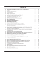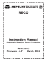
1
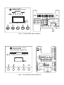
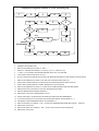
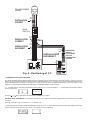
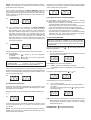
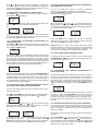
REGO
Instruction Manual
Automatic Reactive Power Controller
Revision-0
Firmware - 4.01 March, 2004
DUCATI energia
REGO
POWER
1
2
3
5
4
REMOT NC2
5
NC1
3
4
2
C
1
DUCATI
MAINS CONNECTION
OPER.TYPE C.T.POST.
x
10
REACTIVE POWER CONTROLLER
L1
L2
L1
FF1
FF2
F-N
0 230V 400V
L3
L1
N
-
ALARM
RESET
DATA
energia
REACTIVE POWER CONTROLLER
REGO
MADE IN TIALY
L2
L2
L1 -
CT./ 5A
O
400V 230V
+
STE
MAX250VAC 5A
MAX250VAC 3A
L
K
L1
L2
L3
N
AUTO
MAN
Fig-1 - Front and Rear panel of Rego-5
STE
MAX250V 6A
RS-485
DUCATI
C1
energia
1
REACTIVE POWER CONTROLLER
2
REGO
3
4
POWER 1
2
3
4
5
6
7
8
9
10
11
5
0
MAINS CONNECTION
OPERATING C.T.
230V
400V 230V O
POSITION
L1
L2
L3
L1
L2
L1
N
L1
L1
-
TYP
FF1
FF2
F-N
400V
x 10
CT../5A
L
-
DATA
ALARM
RESET
AUTO/MAN
NC1
NC2
NC1
NC2
7
8
K
+
6
9
L1
L2
L3
N
10
N.O.
EXT.FAN CONTROL
MAX.250V 6A
11
DUCATI
energia
REACTIVE POWER CONTROLLER
N.O.
REMOT
MAX.250V 6A
Fig-2 - Front and Rear panel of Rego-12
REGO
MADE IN TIALY
12
C2
MAINS -380-415V
N T/23 S/L2R/L1
REGO
K
CT../5A
L
FF1 CONNECTION
400V (V2)
230V (V1)
REGO
K
L
CT../5A
FF2 CONNECTION
400V (V2)
230V (V1)
K
CT../5A
L
F-n CONNECTION
Only for
single phase network
400V (V2)
230V (V1)
USE 200mA
FUSE FOR
VOLTAGE
INPUTS
LOAD
Fig.-3 - Mains Connection
MAINS
N T/23 S/L2R/L1
K
L
CT../5A
REGO STEPS 12
REGO STEPS 7
SEE FIG.3
REGO STEPS 5
400V (V2)
230V (V1)
DV
USE 200mA
FUSE FOR
VOLTAGE
INPUTS
2
1
3
6
8
7
C1
K4
K2
Fig.-4 - Electrical Connections
5
9
10
11
12
C2
K1
LOAD
4
K3
K6
K5
K11
K9
K7
K8
K10
K12
Simplified Diagram relative to First Powering up
1
3
2
11
5
4
9
10
6
NO
YES
12
YES
13
7
NO
14
SELFACQUISITION
15
8
MANUAL
PROGRAMMING
16
17
18
19
20
1.
POWER THE CONTROLLER
2.
DISPLAYALTERNATELY SHOWS “IL” AND “- - -”
3.
ENTER “IL” PARAMETER MAINS C.T. RATIO (e.g. w/ C.T. 200/5 enter 40)
4.
“+” AND “-” TO CHANGE THE PARAMETER AND “DATA” KEY TO CONFIRM
5.
“FAS” DISPLAYED IN TURN WITH “0” OR “1”
6.
IS THE CONTROLLER INSTALLED ON A DUCATI ENERGIA POWER FACTOR CORRECTION SYSTEM?
7.
DISPLAYALTERNATELY SHOWS “COS” AND THE SYSTEM POWER FACTOR
8.
STEPS SWITCHED IN AND OUT OF SERVICE TO ACHIEVE DESIRED POWER FACTOR
9.
STEPS SWITCHED IN AND OUT THREE TIMES (AUTO-ACQUISITION)
10. DISPLAYALTERNATELY SHOWS “C1” AND THE VALUE MEASURED FOR THE FIRST BANK
11. PRESS “DATA” KEY TO DISPLAY VALUE OF SUBSEQUENT BANKS
12. ARE THE MEASURED POWERS CORRECT?
13. PRESS THE “DATA” KEY THREE TIMES TO EXIT
14. STARTA NEW SELF-ACQUISITION OR CARRY OUTA MANUAL PROGRAMMING
15. TO LAUNCH A NEW AUTO-ACQUISITION PROCEDURE PRESS “ALARM/ RESET” + “+”
16. FOR MANUAL PROGRAMMING PRESS ALARM/RESET” +“-”
17. DISPLAY SHOWS “Pro” PRESS “+” OR “-” TO SET THE DESIRED PROGRAM (SEE TABLE 1 - PAGE 72)
18. PRESS THE “DATA” KEY
19. DISPLAY SHOWS “PPC” PRESS “+” OR “-” TO SET THE VALUE OF THE FIRST BANK
20. PRESS THE “DATA” KEY
CONTENTS
(1)
(2)
(3)
(4)
(5)
(6)
(7)
(8)
(9)
(10)
(11)
(12)
12.1
12.2
12.3
12.4
12.5
12.6
12.7
12.8
12.9
(13)
13.1
13.2
13.3
13.4
13.5
13.6
13.7
(14)
(15)
(16)
(17)
SIMPLIFIED DIAGRAM RELATIVE TO FIRST POWERING UP
SAFETY
GENERAL DESCRIPTION
HOW IT WORKS
MAINS CONNECTION
INSTRUCTIONS FOR INSTALLING THE. CT.
POWERING UP FOR THE FIRST TIME
SUBSEQUENT STARTUPS
TESTING CONTROLLER PERFORMANCE
SETUP PARAMETERS
DISPLAY OF MEASUREMENTS
ADDITIONAL FUNCTIONS
MANUAL OPERATING MODE
DISPLAYING THE POWERS OF SINGLE STEPS
PROCEDURE FOR CHECKING THE EFFICIENCY
OF THE SINGLE STEPS
PROCEDURE FOR ENABLING/DISABLING OUTPUT RELAYS IN THE
AUTOMATIC OPERATING MODE
DISPLAYING THE COUNTER OF TOTAL OPERATIONS PERFORMED
BY EACH RELAY
DISPLAYING THE SOFTWARE RELEASE
PROCEDURE FOR TESTING CONNECTIONS TO CAPACITOR STEPS
GENERATOR POWER FACTOR CORRECTION MODE
TOTAL RESETTING OF SETUP PARAMETERS
SIGNALS AND ALARMS
SIGNALING OF POWER FACTOR CORRECTION FAILURE
OVER VOLTAGE SIGNAL
OVER TEMPERATURE PROTECTION
PROTECTION AGAINST EXCESSIVE HARMONIC DISTORTION
PROTECTION AGAINST MAINS VOLTAGE DIPS AND DROPS
DISPLAY OF ALARM COUNTERS
CHANGING THE ALARM ACTIVATION MODES
HIDDEN MENU
LIST OF MAIN KEYS AND ASSOCIATED FUNCTIONS
TROUBLESHOOTING
TECHNICAL SPECIFICATIONS
...........
...........
...........
...........
...........
...........
...........
...........
...........
...........
...........
...........
...........
...........
52
56
57
58
59
60
62
64
65
65
75
75
75
76
...........
77
...........
77
...........
...........
...........
...........
...........
...........
...........
...........
...........
...........
...........
...........
...........
...........
...........
...........
...........
78
79
79
80
81
82
82
83
84
84
85
86
86
87
91
92
94
2) SAFETY
NOTE: The front panel of REGO features a series of keys
for accessing functions and programming; some functions
are activated by pressing a combination of 2 keys: in this
manual, when mention is made of a two-key combination
(e.g. AUTO/MAN +
), it means that the user must press
the first key and, without releasing it, then press the second
one. (In fact the combination AUTO/MAN +
activates a
+ AUTO/MAN.
different function from the combination
This automatic power factor correction controller was
manufactured and tested in conformity with current standards and
left the factory in perfect conditions of technical safety.
In order to maintain these conditions and ensure safe operation,
the user must abide by the instructions provided herein.
WARNING
This device must be installed by qualified personnel in
accordance with the equipment regulations currently in
force in order to prevent injury or damage to
persons or property.
Maintenance or repair work
must be managed solely by authorized personnel.
Before undergoing any maintenance or repairs,
the device must be disconnected from all power sources.
DUCATI ENERGIA s.p.a. disclaims all liability for any injury or
damage caused to persons or property as a result of improper use
of its products.
In view of the continuous evolution of our technology, we reserve
the right to change the specifications contained herein without
notice. The catalogue descriptions and data shall thus have no
contractual validity.
3) GENERAL DESCRIPTION
The REGO reactive power controller is designed to control and
regulate capacitor banks. It operates on the basis of
microprocessor technology, which provides accurate, reliable
power factor measurements. The power factor is controlled by
switching capacitor banks according to the reactive power
requirements of the load: if more than one step is needed in order
to reach the cos. required, REGO activates all the steps
necessary with a delay between one and the other equal to the set
time “T2”. The number of switching operations is thereby reduced
and where the capacitor banks have an equal value, they will be
used in a homogeneous manner.
The controller features both automatic and manual operating
modes. In addition, the powers associated with the steps can be
automatically acquired thanks to the “Auto Acquisition” function.
At the end of this procedure, moreover, the controller also
automatically selects the most appropriate switching sequence.
Alternatively a user program, chosen among the numerous
available options, can be manually set. Thanks to this function the
controller will be able to intervene and correct the system PF more
quickly: in fact, on the basis of real-time power measurements and
the known powers associated with individual steps, it can
calculate how much reactive power is needed to bring the cos. to
the desired value and switch on all the necessary steps together
(with just a settable delay “T2” between one and the next), as
noted previously.
4) HOW IT WORKS
The measured current from the mains C.T. is filtered and
compared with the required power factor and the insensitivity
zone: if the conditions set by the user thus require, the
(or
)
LED will light up and all the banks necessary in order to reach the
set power factor will be switched into service in as little time as
possible (compatibly with the capacitor discharge time T1).
The controller automatically adjusts to the direction of circulation
of the current drawn from the C.T.
If the current to the C.T. secondary winding falls below 200mA,
the controller will disconnect all the banks and the display will
show“COS” in turn with flashing “.-.-.” .
It will go into standby until a current exceeding that value is
restored.
5) MAINS CONNECTION
The REGO reactive power controller may be connected to the
mains according to three different configurations (see diagram in
Fig. 3 - Page 3).
“FF1” In this configuration (default) the C.T./5A is positioned on
phase R(L1) and the reference voltage is drawn from the
line voltage between phases S(L2) and T(L3). This is the
classic varmetric connection. This is the type of
connection utilized in DUCATI ENERGIA automatic
power factor correction systems.
“FF2” In this configuration the C.T./5A is on phase R(L1)
whereas the reference voltage is the line voltage
between phase R(L1) itself and phase S(L2).
Warning: if the cyclical direction of the power supply phases is
not known, configuration FF2 may give rise to an error in the
power factor measurement.
“F-n” In this configuration the C.T./5A is on phase R(L1)
whereas the reference voltage is the phase-neutral
between phase R(L1) itself and the neutral N. Use this
configuration only for single-phase networks.
6) INSTRUCTIONS FOR INSTALLING THE C.T.
The 7- or 12-step model also features an Rs485 serial interface
with
standard “DUCATI” communication protocol which enables the
user to
connect the device to a network of instruments and read the
measured data remotely from a connected PC.
The C.T. must have a value:
–
–
REGO also offers other useful functions, such as panelboard
temperature measurements for controlling an external cooling fan
(in
the 7- or 12-step model), a series of protections and associated
alarms to safeguard the capacitor banks and guarantee efficient
system performance, the possibility of counting the number of
switching operations of a certain step to prevent possible
downtimes due to failures and thereby increase the system’s
reliability, and other functions as well.
at the primary winding: equal to or relatively higher than the
maximum current absorbed by the load downstream from
the C.T. itself.
at the secondary winding: 5A.
VERY IMPORTANT:
– The C.T. must be connected both upstream from the power
factor correction system and upstream from the load (See
Fig.5 positions a and b).
– The C.T. must never be directly connected on the load power
supply line (See Fig.5 position c) or directly on the power
factor correction line (See Fig.5 position d).
– In the FF1 connection configuration the C.T. must be
connected to the phase not used for the voltmetric supply to
the controller. If the controller is installed on a DUCATI
energia power factor correction system the C.T. phase must
be L1/R; see Fig.5 position a and b).
MT
TRANSFORMER
ROOM
L3
L1
L2
BT
T.A.
C.T.
INSTALLATION
CORRECT
a
MAIN
SWITCH
T.A.
C.T.
INSTALLATION
CORRECT
INSTALLATION
INCORRECT
b
T.A.
C.T.
c
T.A.
C.T.
d
INSTALLATION
INCORRECT
L1 L2
L3
DEDICATED
SWITCH
FOR POWER
FACTOR
CORRECTION
SYSTEM
LOADS
S2
S1
Fig.-5 - Positioning of C.T.
(7) POWERING UP FOR THE FIRST TIME
The REGO regulator behaves differently the first time it is started up since it will need the IL parameter (mains C.T. ratio ) to be set in
order to work; the regulator cannot be started up without setting this parameter. On subsequent occasions it will utilize the previously
programmed parameter, unless the user wishes to change it. As soon as the controller is switched on, 8.8.8. will appear on the
display for a few seconds and all the LEDs will light up to enable their efficiency to be checked.
7.1 The first time the controller is powered the display will show “IL” in turn with flashing “- - -” and remain in this situation until the
mains CT ratio is set;
press the
or
key to change the parameter and the DATA key to confirm.
SETTING THE IL PARAMETER: for example, if the user has a C.T. with a ratio of 200/5, the parameter to set must be IL= 40 (mains
CT ratio);
Other Eg: CT 300/5 IL=60; CT 350/5 IL=70; CT 400/5 IL=80.
7.2 Subsequently the controller will alternately display “FAS” an1 “0” or “1”; at this stage the system will read and display the direction
of the incoming current from the C.T. (0 = direct / 1= inverted). It is only an indication.
NOTE: if the incoming current is insufficient (less than 200mA),
REGO cannot determine its direction and will stand by in this
status until current is supplied.
At this point, the controller no longer requires any type of setting
and will be ready for perfect operation: it will alternately display
“COS” and the system power factor.
If the controller is installed on a DUCATI ENERGIA automatic
power factor correction system (pre-programmed controller), no
type of setting will be required and the controller will be ready for
perfect operation: it will alternately display “COS” and the power
factor of the system.
Ex.
9) TESTING CONTROLLER PERFORMANCE
Ex.
7.3 If the controller is not installed on a DUCATI ENERGIA
automatic power factor correction unit (virgin controller),
after displaying the “FAS” parameter it will automatically
launch the automatic procedure for acquiring the powers of
the single capacitor steps. The capacitor steps will be
switched on and measured in sequence a total of three times
each. At the end of this procedure the controller will
alternately display “C1” and the measured power value of the
first step; the power of the next step can be displayed by
pressing the DATA key.
Ex.
To immediately check whether the controller is working
efficiently, the user should keep in mind that:
– When the load is started, the controller should turn on the
LED and switch the capacitor steps into service.
– If the load is reduced or removed, the controller should turn
on the LED and disconnect capacitor steps accordingly.
– When the and LEDs are off, the controller should display a
cos. close to the one set (see chap.10.2 - Page 66).
– As the inductive cos. increases up to 1, the current circulating
upstream from the power factor correction decreases,
whereas it increases with the capacitive cos.
10) SETUP PARAMETERS
N.B.:If the controller is installed on a DUCATI energia
automatic power factor correction system we advise the
user not to change any setup parameters with the exception
of COS and IL.
To enter the setup menu press
following parameters:
If the power measurements are incorrect, from the same menu
the user can press:
–
ALARM/RESET +
to launch a new auto acquisition
procedure
–
ALARM/RESET +
to enter the manual programming
mode (see chap.10.8 - Page 68)
NOTE: FOR A CORRECT WORKING OF THE
CONTROLLER,
C H E C K T H AT P O W E R S
MEASURED BY THE CONTROLLER ARE CORRECT.
If the power measurements are correct, the user can press the
DATA key for three seconds to exit this menu and the controller will
start to work automatically, displaying the letters “COS” in turn
with the system power factor.
+
. The display will show the
10.1 “Fr” = Mains frequency.
The “Fr” parameter is displayed in turn with the measured
value. It is only an indication.
Press DATA to go on to the next parameter
10.2 “COS” = Power factor desired in the system.
The “COS” parameter is displayed in turn with the default
value “0.95”.
The value can be changed using the
or
key.
Ex.
Press DATA to go on to the next parameter
8) SUBSEQUENT STARTUPS
As soon as the controller is switched on, 8.8.8. will appear on the
display for a few seconds and all the LEDs will light up to enable
their efficiency to be checked.
10.3
“UFF” = Mains voltage
The “UFF” parameter is displayed in turn with the default
value “400”.
The value can be changed using the
or key (possible
values 400 or 230).
Subsequently the controller will alternately display “FAS” and “0”
or “1”;
Ex.
at this stage the system will read and display the direction of the
incoming current from the C.T. (0 = direct / 1= inverted). It is only
an indication.
NOTE: if the incoming current is insufficient (less than 200mA),
REGO cannot determine its direction and will stand by in this
status until current is supplied.
N.B.: If the controller is powered by an auxiliary transformer, the
UFF parameter should be set at the rated primary voltage
of the auxiliary transformer (range 100..700). To change
this parameter, press:
ALARM/RESET +
ALARM/RESET +
to increase the value.
to decrease the value.
DO NOT CHANGE THIS PARAMETER IF THE CONTROLLER
IS INSTALLED ON A DUCATI ENERGIA POWER FACTOR
CORRECTION SYSTEM.
AUt = a new automatic acquisition procedure will be carried out.
Press DATA to go on to the next parameter
10.4 “IL” = Mains C.T. ratio.
The “IL” parameter is displayed in turn with the value
previously set by the user.
The value can be changed using the
or
key.
Setting examples:
C.T. 300/5 IL =60; C.T. 350/5 IL=70; C.T. 400/5 IL=80
Ex.
Press DATA to go on to the next parameter
10.5 “COn” = Type of connection of controller to mains.
“COn” is displayed in turn with the default value “FF1”.
The user can change this parameter using the
or
key
(possible settings: FF1, FF2, F-n - see chap 5 - Page 59).
DO NOT CHANGE THIS PARAMETER IF THE
CONTROLLER S INSTALLED ON A DUCATI ENERGIA
POWER FACTOR CORRECTION SYSTEM.
Press DATA to go on to the next parameter
10.6 “SUP” = Setting of terminal used to power the controller.
“SUP” is displayed in turn with the default value “U2”.
The capacitor steps will be switched on and measured in
sequence a total of three times each. At the end of this procedure
the controller will alternately display “C1” and the measured
power value of the first step; the power of the next step can be
displayed by pressing the DATA key.
Press DATA for three seconds to go on to the next parameter.
Pr = the switching logic & power of the single steps is manually
set.
When the letters “Pro” appear, select the desired program (see
Table 1 - Page 72) using the
or
key and press DATA to
confirm.
Thereafter, when the letters “PFC” appear, set the value in kVAr
of the first power factor correction capacitor bank (always
connected to output terminal “1”), again using the
or
key;
Example: if you have an automatic 100kVAr system with power
70 steps of 10-10-20-20-40 the parameters should be set as
follows:
Pro = 26 (see Table 1 - Page 72)
PFC = 10.
Press DATA to confirm and go on to the next parameter.
The user can change this parameter using the
or
key
(possible settings: U1/230V, U2/400V).
DO NOT CHANGE THIS PARAMETER IF THE
CONTROLLER IS INSTALLED ON A DUCATI ENERGIA
POWER FACTOR CORRECTION SYSTEM.
SWITCHING LOGICS
The controller can adopt one of three logics to switch the
capacitor banks in and out of service in order to achieve and
maintain the set cosphi, i.e.:
LINEAR LOGIC
This logic is identified by the code 1:1:1 and presupposes the
condition that all capacitor banks have equal powers. Given a
situation such as the one illustrated in the table,
Press DATA to go on to the next parameter
Bank No.
10.7 “FAS” = Activation or deactivation of automatic adjustment
of mains C.T. direction.
“FAS” is displayed in turn with the default value “0n”
(autoadjustment enabled).
The parameter can be changed using the
or
key
(possible settings: On/auto-adjustment, blo/C.T. direction
fixed).
DO NOT CHANGE THIS PARAMETER IF THE
CONTROLLERS INSTALLED ON A DUCATI ENERGIA
POWER FACTOR CORRECTION SYSTEM.
Status
1
2
3
4
5
6
OFF
ON
ON
ON
OFF
OFF
the controller will switch on bank no. 5 if a bank needs to be
switched into service and switch off bank no. 2 if one needs to be
switched off. This will ensure that all the banks will work and as a
result component wear will be evenly distributed among them.
GEOMETRIC LOGIC
It is identified by the code 1:2:4 and presupposes the condition
that each bank has a power equal to or at most double the power
of the one that precedes it. Assuming that the banks have powers
as shown in the table,
Bank No.
1
2
3
4
5
6
Power
10
20
40
40
40
80
10.8 “ACq” = Menu for launching the procedure for acquiring the
power of single steps and setting their switching logic.
“ACq” is displayed in turn with the default value “no”.
The parameter can be changed using the
or
key and
confirming by pressing DATA; the possible settings are:
no = no acquisition procedure will be carried out.
and that the load requires 50 kVAr, the controller will switch on the
1st, 2nd and then 3rd banks, thereby reaching 70 kVAr. At this
point it will switch off the 1st and then the 2nd, which will bring it to
40 kVAr, and finally it will switch the 1st back on to reach 50 kVAr.
As may be observed, this logic makes it possible to obtain a large
number of steps with a limited number of banks. However, the
number of switching operations is not evenly distributed among
the banks, resulting in greater wear on the first ones.
SEMI-GEOMETRIC LOGIC
It is identified by the code 1:2:2 and the power of the first bank
must be half that of the others, which must all be equal. The first
bank is managed according to a geometric logic whereas all the
others, which have equal powers, are managed according to a
linear logic.
Parameter
Description
Range
(10.1) Fr
Measured mains
Freq. only an indication
50 or 60 Hz
(10.2) COS
Power factor to be
0.8IND ÷
achieved within the system 0.8CAP
0.95
400
(10.3) UFF
Voltage rating of controller
230 or 400
IMPORTANT: the first output relay must always be connected to
the capacitor bank with the least power. If the powers of the steps
are all equal, only make sure that the first step is not left without
controlled capacitors. Moreover, in the event that a specific user
program is configured (as in Table 1), the value of the first bank
must be set.
(10.4) IL
Mains C.T. ratio.
Eg: with CT100/5 set 20
Eg: with CT200/5 set 40
1...3000
(10.5) Con
Type of connection
of controller to mains.
FF1
FF2
F-n
10.9 “s:s:s:” = Display of set logic At the end of an automatic
acquisition or manual setting procedure, the controller will
display a switching sequence and 72 will start to work
automatically. If the controller cannot identify an optimal
sequence, it will set the 1:1:1 logic.
Ex.
(10.6) SUP
Setting of terminal used
to power the controller.
U1 (230V)
U2 (400V)
Auto-adjustment of
mains C.T. direction:
On=auto-adjustment
blo= fixed direction
On
blo
(10.7) FAS
(10.8) ACq
Press DATA to go back to the first parameter in the menu. To
exit the setup menu, keep the DATA key pressed down for
three seconds
IMPORTANT: If the controller is installed on a DUCATI
ENERGIA power factor correction system, we advise the user
not to change the default parameters (See Table 2 - Page 74).
Program N°
Sequence
N° OF
Pr1
1:1:1
2
DESCRIPTION
Setting of N° of
steps and power of
bank connected to the
first output relay.
Pr2
Pr3
Pr4
Pr5
Pr6
Pr7
Pr8
Pr9
Pr10
Pr11
Pr12
Pr13
Pr14
Pr15
Pr16
Pr17
Pr18
Pr19
Pr20
Pr21
Pr22
1:1:1
1:1:1
1:1:1
1:1:1
1:1:1
1:1:1
1:1:1
1:1:1
1:1:1
1:1:1
1:2:2
1:2:2
1:2:2
1:2:2
1:2:2
1:2:2
1:2:2
1:2:2
1:2:2
1:2:2
1:2:2
3
4
5
6
7
8
9
10
11
12
2
3
4
5
6
7
8
9
10
11
12
“
“
“
“
“
“
“
“
“
“
“
“
“
“
“
“
“
“
“
“
“
Pr23
Pr24
Pr25
Pr26
Pr27
Pr28
Pr29
Pr30
Pr31
Pr32
Pr33
1:2:4
1:2:4
1:2:4
1:2:4
1:2:4
1:2:4
1:2:4
1:2:4
1:2:4
1:2:4
1:2:4
2
3
4
5
6
7
8
9
10
11
12
“
“
“
“
“
“
“
“
“
“
“
Table 1: User programs (selection of SEQUENCE and N° OF
STEPS)
Acquisition of step power:
no = no acquisition
procedure
no
AUt=automatic acquisition Aut
Pr = manual setting
Pr
(10.9) s:s:s: Display of set logic
1:1:1
1:2:2
1:2:4
Default
-/-
FF1
U2
On
no
-/-
Table 2: Setup parameters
11) DISPLAY OF MEASUREMENTS
Normally the display shows the system cos..
A minus sign indicates a capacitive power factor.
N.B.: In the event of a power cut, the controller will not be able to
calculate the cos phi and will alternately display “ C.O.S.” & “-.-.-.”.
Press the DATA key to display the measurement readings: every
time you press, the next parameter will be displayed.
The parameters are displayed in the following sequence:
“COS” (system power factor)
“UFF” (effective measured line voltage)
“IL”
(line current measured at the primary winding of the CT)
“PA”
(equivalent active power absorbed by load, in kW)
“PL”
(equivalent reactive power absorbed by load, in kVAr)
“thd” (crest factor normalized to 1: values less or greater than
1 if harmonic distortion is present)
o
“ C”
(temperature inside panel board enclosure at the point
where the controller is installed; the value shown may be
considered reliable after about 1 hour of operation)
12) ADDITIONAL FUNCTIONS
12.1 MANUAL OPERATING MODE
Press the AUTO/MAN key for about two seconds until the
corresponding LED lights up: the controller is now ready to be
programmed in the manual mode.
The user must indicate the desired status for every output relay:
at the end of the programming procedure, the controller will set all
the capacitor steps in the status requested. Operatively, REGO
indicates
“r1” in turn with the status (which can be “On” or “OFF”);
Ex.
press
or
to choose the status of the relay you want to set in
the manual operating mode; press the DATA key to display the
status of the subsequent relay. After viewing the status of the last
relay, press the DATA key to exit this function.
12.2 DISPLAYING THE POWERS OF SINGLE STEPS
Press DATA +
to access the relevant menu (“CP” will appear
on the display and
will flash);
when the
key is pressed, REGO will alternately display “C1”
and the value in kVAr associated with the first step.
Ex.
12.5 DISPLAYING THE COUNTER OF TOTAL OPERATIONS
PERFORMED BY EACH RELAY
The user can display the number of switching operations
performed by each relay controlling the capacitor banks.
Press + AUTO/MAN to access the relevant menu (the display
will show “Cnt” and
will flash).
When you press the
key, the
+
LEDs will flash and the
display will show the operation performed by the first output relay.
“C1” will appear, followed by the number of switching operations.
A “.” is used to separate thousands.
Ex.
Every time you press the DATA key, the controller will show the
powers of the individual steps in sequence; after viewing the last
step press the DATA key to exit this function.
12.3 PROCEDURE FOR CHECKING THE EFFICIENCY OF
THE SINGLE STEPS
Press DATA +
to access the menu pertaining to the procedure
for checking the powers of the capacitor steps (the display will
show “ChP” and
will flash).
Press the DATA key to display the number of switching
operations of the next relay; after viewing the data of the last
relay, press the DATA key to exit the function.
Important: when an output relay counter totals over 100,000
switching operations, the LED corresponding to the step will flash
to warn of the need to overhaul/replace the contactors. The
output will not be disabled, only a warning will be signaled.
12.6 DISPLAYING THE SOFTWARE RELEASE
Pressing the
key will cause REGO to switch off all the banks
and start the procedure for measuring the power of all the steps
(the cycle will be launched three times to provide a better
measurement). If REGO detects differences of more than 25% in
the power that was associated with the step during the previous
auto-acquisition procedure, the corresponding LED will flash. At
the same time the letters “rSt” will appear on the display
To display the software release number of the controller, press
ALARM/RESET + DATA: the display will alternately show “Flr”
and the firmware version “x.xx”.
12.7 PROCEDURE FOR TESTING CONNECTIONS TO
CAPACITOR STEPS
and the user must disable the step by pressing ALARM/RESET; if
this key is not pressed within a few seconds, the operation will be
terminated without any effect taking place. Once the check is
completed, REGO will function as before, with the exclusion of
any steps detected to be faulty, whose LEDs will continue flashing
to signal their status of unavailability.
12.4 PROCEDURE FOR ENABLING/DISABLING OUTPUT
RELAYS IN THE AUTOMATIC OPERATING MODE
An automatic procedure is provided to make it easier to check the
efficiency of connections to the capacitor steps, independently of
the mains network status and the presence of current on
terminals “K” ed “L”. This procedure can be launched by pressing
DATA + AUTO/MAN regardless of the current controller situation
(“tSt” will appear on the display and the AUTO/MAN LED will
flash);
The user can decide which relays the controller must not use in
the automatic mode.
Press
+ AUTO/MAN to access the menu for enabling/disabling
the output relays (the display will show “Abi” and
will flash).
When you press the
key, the
+
LEDs will flash and the
display will start showing the status of the first relay: “r1” will be
displayed in turn with its status (“On” or “OFF”).
Ex.
if the procedure is launched during normal operation, it will be
necessary to press the AUTO/MAN key for about another 2
seconds to confirm the launching of the test. The procedure
consists in switching on the individual steps in sequence at twosecond intervals. The closing time of an individual step is five
seconds.
12.8 GENERATOR POWER FACTOR CORRECTION MODE
To correct the power factor of the generators, the user must set
this operating mode, which involves inhibiting the automatic
mains CT direction adjustment function and configuring the
signals accordingly.
This operation must be carried out with the mains powered by the
generator.
At this point you can choose the status of the relay, pressing the
key to switch it “On” or the
key to switch it “OFF”. Press the
DATA key to display the status of the next relay; after viewing the
status of the last relay, press the DATA key to exit this function.
Press AUTO/MAN +
to access the menu for fixing the C.T.
direction. When you press the keys, the
LED will flash and
you must press the corresponding key. At this point the
and
LEDs will flash and the controller will simultaneously display
“Inu” (INV) in turn with “On” or “OFF”.
13.2 OVERVOLTAGE SIGNAL
This signal is activated when the controller measures a supply
voltage exceeding the maximum allowed by the transformer (230
+19%; 400 +19%) for longer than 30 seconds.
To set the appropriate operating mode for correcting the power
factor of generators, press the key: the word “On” will appear. If,
on the contrary, you wish to enable the C.T. direction autoadjustment function
(in the case of traditional power factor correction of loads) press
the key: the word “OFF” will appear to confirm the selection
.
12.9 TOTAL RESETTING OF SETUP PARAMETERS
This command reinstates all the default parameters and returns
the controller to the initial starting up condition; after this
operation, reset the controller by following the directions in
chapter 7 for POWERING UP FOR THE FIRST TIME (after
setting the IL parameter, the controller always starts the
procedure for acquiring banks, see chap. 7.3 - Page 63).
Press
+
to access the setup menu and press the DATA key
repeatedly until the set logic (1:1:1, 1:2:2, 1:2:4) is displayed; to
reset the controller, keep ALARM/RESET pressed for 5 seconds.
The letters “CLr” will be displayed in turn with the default setting
“no”.
The parameter can be changed using the
or
key and
confirming with the DATA key. The possible choices are:
no = no reset will be carried out.
yes = the parameters will be reset; during this phase the
controller will switch off all the steps and the digits 8.8.8. will
appear for a few seconds with all LEDs illuminated
13) SIGNALS AND ALARMS
The REGO controller features a device for signaling overvoltage
and power factor correction failures as well as alarms which are
activated when an overtemperature protection trips or in the event
of excessive harmonic distortion and voltage drops or mains dips.
When a protection trips, the ALARM LED will light up and the NC
contact will close to remotely signal the alarm status. With the
exception of the device for signaling power factor correction
failures and overvoltage, the protections will cause the capacitor
banks to be switched off.
13.1 SIGNALING OF POWER FACTOR CORRECTION
FAILURE
This signal is activated when the system power factor remains
below the set value for more than two consecutive hours
(reentries of up to 1 minute are allowed) with all the capacitor
banks switched on. This signaling function is not active in the
manual mode. When a power factor correction failure is signaled:
– the initials “A.L.A.” will be displayed in turn with “C.O.S. ” and the
last value measured (these digits will also be separated by ...)
Ex.
–
–
the ALARM LED situated on the front panel of the controller
will light up.
the alarm relay contact connected to the controller terminal
block will open.
This protection is active even if no capacitor bank is currently
switched on. When this alarm is triggered:
– the initials “A.L.A.” will be displayed in turn with “U.F.F.” and the
last value measured (these digits will also be separated by ...)
Ex.
– the ALARM LED situated on the front panel of the controller
will light up.
– the alarm relay contact connected to the controller terminal
block will open.
– the number shown by the UFF alarm counter will increase by
one.
After 30 minutes all these actions will be cleared and the
controller will automatically resume operation (auto-reset
status A.r.), though the incident will continue to be signaled via
the display, which will show “A.L.A.” in turn with “U.F.F.” and
the last value measured. To clear the display press
ALARM/RESET.
13.3 OVERTEMPERATURE PROTECTION
This protection will trip if the temperature around the controller
exceeds 700C for at least 15 seconds.
When this alarm is triggered:
– the initials “A.L.A.” will be displayed in turn with “°.C.. ” and the
last temperature read (these digits will also be separated by ...).
Ex.
–
–
–
the ALARM LED situated on the front panel of the controller
will light up.
the alarm relay contact connected to the controller terminal
block will open.
the controller will activate the procedure for rapid
disconnectionof all steps and go into a standby status (in
this status the controller will not work).
After 30 minutes all these actions will be cleared and the
controller will automatically resume operation (auto-reset status
A.r.), though the incident will continue to be signaled via the
display, which will show “A.L.A.” in turn with “°.C.. ” and the last
value measured.
To clear the display press ALARM/RESET.
This protection is also active in the manual mode and even if no
capacitors are switched on.
13.4 PROTECTION AGAINST EXCESSIVE HARMONIC
DISTORTION
This protection will trip when the rate of current harmonic
distortion may pose a hazard to the power factor correction
capacitors.
When this alarm is triggered:
– the initials “A.L.A.” will be displayed in turn with “t.h.d. ” and the
measured Crest Factor (these digits will also be separated by ...).
Ex.
After 30 minutes all these actions will be cleared and the controller
will automatically resume operation (auto-reset status A.r.),
though the incident will continue to be signaled via the display,
which will show “A.L.A.” in turn with “C.O.S. ” and the last value
measured.
–
To clear the display press ALARM/RESET.
–
–
–
the ALARM LED situated on the front panel of the controller
will light up.
the alarm relay contact connected to the controller terminal
block will open.
the number shown by the t.h.d. alarm counter will increase by
one.
the controller will activate the procedure for rapid
disconnection of all steps and go into a standby status (in
this status the controller will not work).
After 30 minutes all these actions will be cleared and the controller
will automatically resume operation (auto-reset status A.r.),
though the incident will continue to be signaled via the display,
which will show “A.L.A.” in turn with “t.h.d.” and the measured
Crest Factor.
To clear the display press ALARM/RESET.
This protection is also active in the manual mode.
13.5 PROTECTION AGAINST MAINS VOLTAGE DIPS AND
DROPS
This protection trips in the presence of mains voltage dips lasting
more than two periods (40mS at 50Hz, 33mS at 60Hz). In such
cases, also in the manual mode, the controller will instantly deenergize all the output relays in order to protect the capacitors. It
will then resume its normal control functions, switching steps into
service as necessary after the time T1 has elapsed.
If the voltage dip lasts longer than two cycles, or the voltage drops
below the minimum required to power the device correctly, the
“powerfail” cycle will be activated: REGO will instantly deenergize all the output relays until the voltage returns to normal
levels or disappears completely to prevent undesired operations
on the capacitor banks.
13.6 DISPLAY OF ALARM COUNTERS
The user can see how many times the controller has gone into an
alarm status due to overvoltage & excessive harmonic distortion.
To view the counters, press
+ DATA. The letters “ALC” will
appear and the
LED will flash.
Ex.
14) HIDDEN MENU
Some REGO parameters are present in the hidden menu. These
settings may be accessed by the user only when setting the C.T.
ratio.
To access the menu, press + and while the “IL” parameter is
shown on the display, keep the ALARM/RESET + DATA keys
pressed down until the display shows:
“t1” in the case of five-step versions of REGO
“FAn” in the case of seven- and twelve-step versions of REGO
At this point you have entered the hidden menu. All the
parameters of this submenu can be changed using the
+
keys. To go on to thenext parameter, press the DATA key. The
parameter sequence is asfollows:
– (“FAn”) Temperature threshold for closing the N/O relay that
controls the external fan (this parameter is available only for
sevenand twelve-step versions of REGO, it is suggested not to
modify).
– (“t1”) Display of T1, the time for which steps are unavailable
for re-activation (you are advised not to change this parameter).
– (“t2”) Display of T2, the delay between the closing of two relays
controlling consecutive steps (you are advised not to change this
parameter).
Press the corresponding key to access the settings. The s and
LEDs will flash and the first alarm (t.h.d.) will be displayed in
turn with the number of activations; to view the next alarm (UFF)
press the DATA key. Press the DATA key again to exit the
function.
These counters cannot be cleared.
13.7 CHANGING THE ALARM ACTIVATION MODES
The user can change the activation modes of the controller
alarms. In particular, as regards the signals and protections for
power factor correction failures, overvoltage, overtemperature
and excessive harmonic distortion, it is possible to set:
–
ON status: this has the functions described previously, except
that the auto-reset (A.r.) function will not be active and the
controller will remain in a standby status until you press the
ALARM/RESET key on the front panel. Pressing this key will
enable the controller to resume normal operation.
–
OFF status: the protection and alarm or signaling function and
all their consequent actions are completely inhibited. The
user should be fully aware of the risks of choosing the OFF
status; as a rule it is an unadvisable choice, since it may give
rise to potentially hazardous situations.
–
A.r. status (auto-reset-default status): it has the functions
described previously.
– (“HU”) Setting of the Voltage Transformation Ratio. If the
controller is powered via a VT (refer to chapter 10.3 - “UFF”
parameter), it is recommended to adjust the “UFF” parameter
rather than changing HU.
– (“StH”) Setting of trip time of the harmonic distortion alarm
t.h.d.
The possible settings are 1,2,3. If you set 1, the trip time will be
proportional to the level of harmonic distortion; setting 2 will
double this time; setting 3 will quadruplicate the time (you are
advised not to change this parameter).
– (“Adr”) Instrument address for Rs485 network connection to
other instruments and a PC (this parameter is available only for
seven and twelve-step versions of REGO).
When the controller is turned on for the first time, the default statu
of all alarms is A.r. To access the menu, press AUTO/MAN
+;
the letters “ALP” will appear and the
LED will flash.
– (“bdr”) Speed of data transmission (Baud Rate) on the
RS485 port. The speed is expressed without the last zero (e.g.
9600bps is shown as “960”; this parameter is available only for
seven- and twelve-step versions of REGO).
Press the corresponding key to access the settings. The s and
LEDs will flash and the first alarm/signal will be displayed; to
change the alarm status press the
+
key and to go on to the
next alarm press the DATA key (°C, UFF, thd, COS); after the last
parameter has been displayed, press the DATA key again to exit
the function.
Press DATA for three seconds to exit the menu.
Parameter
Description
Range Default
Fan
REGO7-12
Temperature threshold (°C)
for tripping fan activation.
5...50
25
t1
Time (in seconds) of
unavailability of a step for
re-activation. Always wait for
capacitors to discharge
before switching them
back on.
5...255
30
Delay time (in units: each
unit corresponds to 500mS)
between the activation
of one step and the next.
1...600 2(=1S)
HU
Mains VT transformation
ratio.
1...1000
1
StH
Setting of trip time of t.h.d.
harmonic distortion alarm.
12.3
-/-
Adr
Address of the instrument
in the Rs485 serial
connection with external
units.
1...99
1
bdr
Speed of data transmission
through the RS485 port
(Baud rate).
1200...
9600
9600
t2
When no bank is switched on, the controller displays a capacitive
cosø. (negative cosø.)
- The controller displays a cos. that does not correspond to the
system’s.
- The controller alternately displays “ C.O.S. ” and “-.-.-.”.
Table 3: Hidden menu parameters
- The controller displays a cos. below the one set and fails to
switch on any banks.
- The controller switches on all the banks even in the absence of
loads and fails to switch them off.
We recommend performing the following checks:
- Check the positioning and connection of the C.T. (See chap. 6 Page 60) INSTRUCTIONS FOR C.T. INSTALLATION)
- Check that a current greater than 200mA is circulating on the
secondary winding of the C.T. (the power factor correction
function requires a working load).
- Check that the setup parameters have been correctly
configured (See chap.10 - Page 65 – SETUP PARAMETERS).
In particular:
- the IL parameter (C.T. ratio – e.g.: with a C.T. 200/5, IL=40)
- the FAS parameter must be “On”
Chap/
section
N.B.:if you wish to reinstate all the default parameter
settings recommended by DUCATI ENERGIA, reset the
controller as directed in chap.12.9 - Page 81 – TOTAL
RESETTING OF SETUP PARAMETERS) and start all over
again from the first powering up procedure (See chap. 7 Page 62 – POWERING UP FOR THE FIRST TIME).
Access the setup menu
10
ALARM/RESET
Reset after alarm condition
13
AUTO/MAN
Manual operating mode
12.1
DATA+
Display the powers of
single steps
12.2
- Check that the generator power factor correction mode (Inu) is
Off (See chap.12.8 - Page 80 – GENERATOR POWER
FACTOR CORRECTION MODE).
- Make sure that the controller has correctly acquired the
powers of the capacitor banks (See chap.12.2 - Page 76 –
DISPLAYING THE POWERS OF SINGLE STEPS).
- Check that the output relays are not disabled (See chap.12.4 Page 77 – PROCEDURE FOR ENABLING/DISABLING
OUTPUT RELAYS IN THE AUTOMATIC MODE)
DATA+
Procedure for Checking the
efficiency of Single Steps
12.3
+AUTO/MAN
Procedure for Enabling /
Disabling Output Relays in
Automatic Mode
12.4
+AUTO/MAN
Display Counter that keeps
track of Operations performed
by ea. Output Relay
12.5
15) List of Main Keys and associated functions
Keys
Function
or
Change the displayed
parameters
DATA
Scan through measurements
and confirm parameter
settings
+
ALARM/RESET+ Display Software Release
DATA
DATA+ AUTO /
Test Procedure for
Contactor Connections
MAN
12.6
AUTO/MAN+
Generator power factor
correction mode
12.8
Display Alarms Counter
13.6
Change alarm activation mode
13.7
+DATA
AUTO/MAN+
Table 4: List of main commands
16) TROUBLESHOOTING
Should the controller show any of these faults
- When powered, the controller remains stuck on “FAS”
12.7
Due to problems of step swing (continuous connection and
disconnection of banks), we suggest to:
- either increase or decrease the “COS” parameter (see chap.
10.2 - Page 66 – Power factor desired in the system) until
reaching a balance condition.
- Increase the “t2” parameter (see chap. 14 - Page 87), thus
delaying the connection of banks.
17) TECHNICAL SPECIFICATIONS
REGO 5/7/12 step power circuit
Supply voltage
380÷415V±10%
220÷240V±10%
Rated frequency
50 or 60Hz (measured and
autonomously set by the
controller)
Input power
8VA max. (REGO 5)
15VA max. (REGO 7/12)
Protection
Internal fuse 250mA T curve.
To protect the instrument
from permanent overvoltage,
the user should install
an external fuse (we
recommend 200mA)
Current input
Rated current
5A
Operating range
0.2...5A
Overload
3 In for 10s
Consumption
0.5VA max. (REGO 5)
1.5VA max. (REGO 7/12)
Measurement and control data
Type of voltage and current
true effective value ( true RMS)
measurement
Power factor control
0.80 inductive ÷ 0.80 capacitive
Step re-connection time lag
5...255s
Relay outputs
Number of outputs
Contact status
Nominal contact capacity
Voltage rating
Alarm relay
Nominal insulation voltage
Max. relay switching power
Measuring precision
Power factor
Active voltage (UFF)
Line current
PC Interface (REGO 7/12)
Serial line
Polarity
Protocol type
5/7/12
N/O
5A - 250V
250Vac
1 N/C contact (3A-250V).
When controller is off, the
contact is N/O.
3kV/1minute
2200W or 1500W - Cosø 0.5
250V
±2%
±2%
±2% value read for I>200mA
(CT secondary winding)
1 RS485 line
terminal A = non-inverting (+)
terminal B = inverting (-)
“Ducati” protocol (character
based)
Ambient operating conditions
Operating temperature
0...+60°C
Storage temperature
–20...+70°C
Connections
Terminal type
Wire size
Enclosure
Construction
Dimensions LxHxP
Hole dimensions
Protection rating
Fixing
Weight
screw terminal (REGO 5)
spring terminal (REGO 7/12)
2.5mm2 max.
Recess mounted with panel
96x96x75mm (REGO 5)
144x144x65mm (REGO 7/12)
91x89mm (REGO 5)
138x138mm (REGO 7/12)
IP40 on front panel, IP20 on
terminal block
With four pressure plates
400g (REGO 5)
800g (REGO 7/12)