1
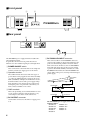
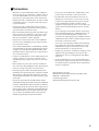
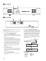
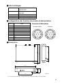
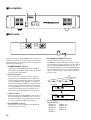
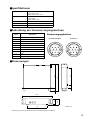
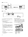
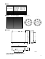
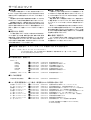
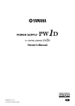
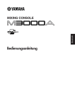
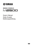
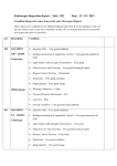
POWER SUPPLY
Owner’s Manual
Mode d’emploi
Bedienungsanleitung
M
FCC INFORMATION (U.S.A.)
1. IMPORTANT NOTICE: DO NOT MODIFY THIS UNIT! This product, when installed as indicated in the instructions contained in this manual, meets FCC
requirements. Modifications not expressly approved by Yamaha may void your authority, granted by the FCC, to use the product.
2. IMPORTANT: When connecting this product to accessories and/or another product use only high quality shielded cables. Cable/s supplied with this product MUST
be used. Follow all installation instructions. Failure to follow instructions could void your FCC authorization to use this product in the USA.
3. NOTE: This product has been tested and found to comply with the requirements listed in FCC Regulations, Part 15 for Class “B” digital devices. Compliance with
these requirements provides a reasonable level of assurance that your use of this product in a residential environment will not result in harmful interference with
other electronic devices. This equipment generates/uses radio frequencies and, if not installed and used according to the instructions found in the users manual, may
cause interference harmful to the operation of other electronic devices. Compliance with FCC regulations does not guarantee that interference will not occur in all
installations. If this product is found to be the source of interference, which can be determined by turning the unit “OFF” and “ON”, please try to eliminate the
problem by using one of the following measures: Relocate either this product or the device that is being affected by the interference. Utilize power outlets that are on
different branch (circuit breaker or fuse) circuits or install AC line filter/s. In the case of radio or TV interference, relocate/reorient the antenna. If the antenna lead-in
is 300 ohm ribbon lead, change the lead-in to coaxial type cable. If these corrective measures do not produce satisfactory results, please contact the local retailer
authorized to distribute this type of product. If you can not locate the appropriate retailer, please contact Yamaha Corporation of America, Electronic Service
Division, 6600 Orangethorpe Ave, Buena Park, CA 90620
The above statements apply ONLY to those products distributed by Yamaha Corporation of America or its subsidiaries.
WARNING: THIS APPARATUS MUST BE EARTHED
IMPORTANT
THE WIRES IN THIS MAINS LEAD ARE COLOURED IN
ACCORDANCE WITH THE FOLLOWING CODE:
GREEN-AND-YELLOW :
EARTH
BLUE :
NEUTRAL
BROWN :
LIVE
As the colours of the wires in the mains lead of this apparatus may
not correspond with the coloured markings identifying the terminals in
your plug, proceed as follows:
The wire which is coloured GREEN and YELLOW must be
connected to the terminal in the plug which is marked by the letter E
or by the safety earth symbol
or coloured GREEN and YELLOW.
The wire which is coloured BLUE must be connected to the terminal
which is marked with the letter N or coloured BLACK.
The wire which is coloured BROWN must be connected to the
terminal which is marked with the letter L or coloured RED.
* This applies only to products distributed by YAMAHA KEMBLE
MUSIC (U.K.) LTD.
2
■Precautions
• Connect the power supply power cord only to an AC
outlet of the type stated in this Owner’s Manual or as
marked on the power supply unit. Failure to do so is a
fire and electrical shock hazard.
• Do not try to modify the power supply unit. This
could be a fire and electrical shock hazard.
• Do not locate the power supply unit in a place subject
to excessive heat or in direct sunlight. This could be a
fire hazard.
• Turn off all audio devices and speakers when connecting to the power supply unit. Refer to the owner’s
manual for each device. Use the correct cables and
connect as specified.
• Do not place the power supply unit in a place subject
to excessive humidity or dust. This could be a fire and
electrical shock hazard.
• Do not plug several devices into the same AC outlet.
This may overload the AC outlet, and could be a fire
and electrical shock hazard. It may also affect the performance of some equipment.
• Do not place heavy objects on the power cord. A damaged power cord is a potential fire and electrical shock
hazard.
• If the power cord is damaged (i.e., cut or a bare wire is
exposed), ask your dealer for a replacement. Using the
power supply unit in this condition is a fire and shock
hazard.
• Hold the power cord plug when disconnecting from
an AC outlet. Never pull the cord. Damaging the
power cord in this way is a potential fire and electrical
shock hazard.
• Do not place small metal objects on top of the power
supply unit. Metal objects inside the power supply
unit are a fire and electrical shock hazard.
• Do not block the power supply unit ventilation slots.
The power supply unit has ventilation slots at the
front to prevent the internal temperature from rising.
Blocked ventilation slots are a fire hazard.
• Leave a reasonable amount of free-air space around
the power supply unit.
• If the power supply unit is to be rack mounted, leave
at least 10 cm free above the top panel and behind the
rear panel. When the power supply unit is in use,
remove the rear of the rack, or open its ventilation
slots to prevent overheating, which could be a fire
hazard.
• The power supply unit operating temperature is
between 5˚C and 35˚C (41˚F and 95˚F).
• If you notice any abnormality—such as smoke, odor,
or noise—turn off the power supply unit immediately.
Remove the power cord from the AC outlet. Confirm
that the abnormality is no longer present. Consult
your dealer for repair. Using the power supply unit in
this condition is a fire and shock hazard.
• If a foreign object or water gets inside the power supply unit, turn it off immediately. Remove the power
cord from the AC outlet. Consult your dealer for
repair. Using the power supply unit in this condition
is a fire and electrical shock hazard.
• If you plan not to use the power supply unit for a long
period of time, remove the power cord from the AC
outlet. Leaving the power supply unit connected is a
fire hazard.
• Do not use benzene, thinner, cleaning detergent, or a
chemical cloth to clean the power supply unit. Use
only a soft, dry cloth.
• The power supply unit uses high-frequency digital circuits that may cause interference on radios and televisions placed close to it. If interference does occur,
relocate the affected equipment.
For European Model
Purchaser/User information specified in EN55103-1 and
EN55103-2.
Inrush Current: 44A
Conformed Environment: E1, E2, E3 and E4.
3
■Front panel
1
2
POWER
OPERATION MONITOR
+48V
+12V
+15V –15V
POWER SUPPLY
NORMAL
ON/
OFF
■Rear panel
5
DC PARALLEL INPUT
CONNECT
4
DC OUTPUT
CONNECT
PIN 2 +15V 5.0A
PIN 5 –15V 5.0A
PIN 6 +12V 5.0A
PIN 9 +48V 0.2A
DISCONNECT
DISCONNECT
3
The PW3000MA power supply should be installed in a
well ventilated location.
In particular, the front and rear panels must not be
blocked, since the ventilation path passes through them.
A POWER ON/OFF switch
After connections to the mixer have been completed,
turn this switch on to supply power to the mixer.
B Operation monitor
These LEDs indicate the status of the four types of
power that are being supplied to the mixer. Normally
(i.e., when no malfunction has occurred), the green
LEDs (NORMAL) will light. If a malfunction occurs,
the LED for that section of the power supply will go
dark. Turn the power off and wait for a time before
turning the power on again. If the same LED(s) are
dark, contact a Yamaha service center.
E DC PARALLEL INPUT connector
This connector allows two PW3000MA units to be
connected in parallel. As shown in the following diagram, use the included parallel connection cable to
make connections. In this case, the two PW3000MA
units will each supply 50% of the power in normal
operation. Even in the unlikely event that one of the
PW3000MA units failed, the other PW3000MA will
supply 100% of the power, ensuring an uninterrupted
power supply.
DC POWER
INPUT
PW3000MA
DC PARALLEL INPUT
CONNECT
DC OUTPUT
DC OUTPUT
CONNECT
PIN 2 +15V 5.0A
PIN 5 –15V 5.0A
PIN 6 +12V 5.0A
PIN 9 +48V 0.2A
DISCONNECT
DISCONNECT
C GND terminals
This is the grounding screw terminal. If hum or noise
occurs, ground (earth) the unit via this jack, or try
connecting it to the chassis of the other device.
DC PARALLEL
INPUT
PW3000MA
DC PARALLEL INPUT
CONNECT
DC OUTPUT
DC OUTPUT
CONNECT
PIN 2 +15V 5.0A
PIN 5 –15V 5.0A
PIN 6 +12V 5.0A
PIN 9 +48V 0.2A
DISCONNECT
DISCONNECT
D DC OUTPUT connector
Connect this connector to the mixer to supply power
to it.
4
The PW3000MA power supply can be used with the
following mixers.
M2500-56C
M3000A-56C
M2500-48C
M3000A-40C
M2500-40C
M3000A-32
M2500-32
M3000A-24
M2500-24
■Specifications
Power Requirements
USA and Canada: 120 V, 60 Hz
Europe: 230 V, 50 Hz
Others: 240 V, 50 Hz
Power Consumptions
USA and Canada: 500 W, 600 VA
Europe: 500 W
Others: 500 W
Dimension (W x H x D)
480 mm x 103.5 mm x 455 mm
Weight
15 kg
Accessories
Parallel connection cable (1 m)
■Power supply cable pin configuration
Pin No.
Power supply connector
Signal name
1
Power supply remote
2
+15 V
3
±15 V GND
4
+48 V GND
5
–15 V
6
+12 V
7
+12 V GND/ power supply remote
8
Power supply remote
9
+48 V
10
FRAME GND
DC OUTPUT
DC PARALLEL INPUT
3
7
2
6
10
1
5
9
1
4
8
4
2
5
8
3
6
9
7
10
292
49.4
56.8
D:455
405.6
■Dimensions
H:103.5
88
W:480
308
Units: mm
• Specifications and appearance are subject to change without notice for improvement.
5
Français
POWER SUPPLY
Mode d’emploi
■Précautions
• Branchez le cordon d’alimentation du bloc d’alimentation à une prise du type décrit dans ce Mode d’emploi ou
sur le bloc d’alimentation. Le non-respect de ces consignes peut provoquer un incendie ou une électrocution
• Ne placez pas le bloc d’alimentation à un endroit soumis
à une chaleur excessive ou en plein soleil. Cela peut provoquer un incendie.
• Ne placez pas le bloc d’alimentation dans un endroit
excessivement humide ou poussiéreux. Cela peut provoquer un incendie ou une électrocution.
• Evitez de brancher plusieurs appareils sur la même prise.
Celle-ci risque d’être surchargée ce qui peut provoquer
un incendie ou une électrocution. Cela peut en outre
altérer les performances d’autres appareils.
• Ne placez pas d’objets lourds sur le cordon d’alimentation. Un cordon endommagé peut provoquer un incendie ou une électrocution.
• Si le cordon d’alimentation est endommagé (entaillé
ou lorsqu’un fil est mis à nu), demandez un nouveau
cordon à votre revendeur. L’utilisation du bloc d’alimentation dans cet état risque de provoquer un incendie ou une électrocution.
• Lorsque vous débranchez le cordon d’alimentation, tirez
toujours sur la prise et pas sur le cordon. Un cordon
endommagé peut provoquer un incendie ou une électrocution.
• Evitez de placer de petits objets sur le bloc d’alimentation. Si de petits objets métalliques s’introduisent dans le
boîtier, il y a risque d’incendie ou d’électrocution.
• Ne bloquez pas les orifices d’aération du bloc d’alimentation. Il est pourvu de fentes d’aération à l’avant
afin d’éviter que la température intérieure ne monte
excessivement. Le blocage de ces fentes peut provoquer
un incendie.
• Laissez un espace libre raisonnable autour du bloc
d’alimentation afin de garantir une bonne ventilation.
• N’essayez pas de modifier le bloc d’alimentation. Cela
peut provoquer un incendie ou une électrocution.
• La température de fonctionnement de la console de
mixage peut se situer entre 5˚C et 35˚C (41˚F et 95˚F).
• Coupez tous les appareils audio ainsi que les enceintes
lors des branchements. Veuillez consulter le mode
d’emploi de chaque appareil. Servez-vous de câbles adéquats et effectuez les branchements selon les consignes
données.
• Si vous remarquez une anomalie (fumée, odeur, bruit),
mettez immédiatement le bloc d’alimentation hors tension. Voyez si l’anomalie disparaît. Consultez votre
revendeur ou le SAV le plus proche. L’utilisation du bloc
d’alimentation dans de telles conditions peut provoquer
un incendie ou une électrocution.
• Si vous n’avez pas l’intention d’utiliser le bloc d’alimentation durant un certain temps, débranchez le cordon
d’alimentation de la prise. Si vous laissez le bloc d’alimentation branché, il y a risque d’incendie.
• N’utilisez pas de benzène, de diluant, de détergent ou un
chiffon de nettoyage chimique pour nettoyer le bloc
d’alimentation. Servez-vous uniquement d’un chiffon
doux et sec.
• Le bloc d’alimentation se sert de circuits numériques à
haute fréquence qui peuvent interférer avec des radios ou
des télévisions placées à proximité. En cas d’interférence,
éloignez vos appareils.
Pour le modèle européen
Informations pour l’acheteur/usager spécifiées dans
EN55103-1 et EN55103-2.
Courant d’appel: 44A
Environnement adapté: E1, E2, E3 et E4
• Si le bloc d’alimentation doit être monté en rack, laissez au moins 10 cm au-dessus de la face supérieure et
derrière la face arrière. Durant le fonctionnement du
bloc d’alimentation, ouvrez la partie arrière du rack
ou ses orifices de ventilation pour éviter toute surchauffe qui pourrait provoquer un incendie.
9
■Face avant
1
2
POWER
OPERATION MONITOR
+48V
+12V
+15V –15V
POWER SUPPLY
NORMAL
ON/
OFF
■Face arrière
5
DC PARALLEL INPUT
CONNECT
4
DC OUTPUT
CONNECT
PIN 2 +15V 5.0A
PIN 5 –15V 5.0A
PIN 6 +12V 5.0A
PIN 9 +48V 0.2A
DISCONNECT
DISCONNECT
3
Le bloc d’alimentation PW3000MA doit être installé dans
un endroit bien aéré.
Evitez surtout de bloquer les faces avant et arrière car la
voie de ventilation passe par l’avant et l’arrière.
A Commutateur POWER ON/OFF
Après avoir effectué les connexions avec la console de
mixage, actionnez ce commutateur pour alimenter la
console.
B Contrôle de fonctionnement
Ces témoins indiquent l’état de fonctionnement des
quatre sources d’alimentation fournie à la console de
mixage. Normalement (s’il n’y a pas de problème), les
témoins verts s’allument (NORMAL). S’il y a un problème, le témoin de la section concernée s’éteint.
Coupez l’alimentation, attendez un certain temps et
remettez le bloc sous tension. Si le ou les mêmes
témoins sont toujours éteints, contactez un SAV
Yamaha.
C Borne GND (masse)
Cette borne accueille la vis de mise à la masse. S’il y a
du bruit ou des bourdonnements, mettez l’appareil à
la masse via cette borne ou en le reliant au châssis de
l’autre appareil.
D Connecteur DC OUTPUT
Reliez ce connecteur à la console de mixage afin de
l’alimenter.
10
E Connecteur DC PARALLEL INPUT
Ce connecteur permet de brancher deux PW3000MA
en parallèle. Comme l’illustration suivante l’indique,
servez-vous du câble de connexion parallèle fourni
pour effectuer les branchements. Dans ce cas, chaque
PW3000MA fournit 50% de l’alimentation. Dans
l’éventualité peu probable qu’un des PW3000MA
tombe en panne, l’autre PW3000MA fournit alors
100% des besoins, garantissant ainsi une alimentation
ininterrompue.
DC POWER
INPUT
PW3000MA
DC PARALLEL INPUT
CONNECT
DC OUTPUT
DC OUTPUT
CONNECT
PIN 2 +15V 5.0A
PIN 5 –15V 5.0A
PIN 6 +12V 5.0A
PIN 9 +48V 0.2A
DISCONNECT
DISCONNECT
DC PARALLEL
INPUT
PW3000MA
DC PARALLEL INPUT
CONNECT
DC OUTPUT
DC OUTPUT
CONNECT
PIN 2 +15V 5.0A
PIN 5 –15V 5.0A
PIN 6 +12V 5.0A
PIN 9 +48V 0.2A
DISCONNECT
DISCONNECT
L’alimentation PW3000MA convient pour les
modèles suivants:
M2500-56C
M3000A-56C
M2500-48C
M3000A-40C
M2500-40C
M3000A-32
M2500-32
M3000A-24
M2500-24
■Fiche technique
Alimentation
USA et Canada: 120 V, 60 Hz
Europe: 230 V, 50 Hz
Autres: 240 V, 50 Hz
Consommation
USA et Canada: 500 W, 600 VA
Europe: 500 W
Autres: 500 W
Dimensions (L x H x P)
480 mm x 103,5 mm x 455 mm
Poids
15 kg
Accessoires
Câble de connexion parallèle (1 m)
■Configuration des broches du cordon d’alimentation
Broche no.
Connecteur d’alimentation
Signal
1
Alimentation (distance)
2
+15 V
3
±15 V masse
4
+48 V masse
5
–15 V
6
+12 V
7
+12 V masse/ alimentation (distance)
8
Alimentation (distance)
9
+48 V
10
Masse au cadre
DC OUTPUT
DC PARALLEL INPUT
3
7
2
6
10
1
5
9
1
4
4
8
2
5
8
3
6
9
7
10
292
49.4
56.8
P:455
405.6
■Dimensions
308
H:103.5
88
L:480
Unités: mm
• Les caractéristiques techniques et l’aspect extérieur peuvent être modifiés sans avis préalable.
11
Bedienungsanleitung
Deutsch
POWER SUPPLY
■Vorsichtsmaßnahmen
• Schließen Sie das Stromkabel der Stromversorgung
ausschließlich an eine Steckdose an, die den Anforderungen in der Bedienungsanleitung oder auf dem
Typenschild entspricht. Sonst besteht nämlich Brandoder Schlaggefahr.
• Modifizieren Sie die Stromversorgung niemals selbst.
Das kann nämlich zu schweren Schäden führen.
Außerdem erlischt der Garantieanspruch.
• Verwenden Sie die Stromversorgung nicht an extrem
warmen Orten bzw. in der prallen Sonne, weil sonst
Brandgefahr besteht.
• Schalter Sie das Pult sowie alle daran angeschlossenen
Geräte aus, bevor Sie die Stromversorgung mit dem
Pult verbinden. Siehe die Bedienungsanleitung der
übrigen Geräte. Verwenden Sie ausschließlich geeignete Kabel.
• Stellen Sie die Stromversorgung nicht an extrem staubige oder feuchte Orte, weil dann Brand- oder Schlaggefahr besteht.
• Schließen Sie niemals mehrere Geräte an dieselbe
Steckdose an. Das könnte die Steckdose nämlich überfordern, so daß es zu einem Kurzschluß bzw. Brand
kommt.
• Stellen Sie keine schweren Gegenstände auf das Netzkabel, um Kurzschlüsse und Brandgefahr zu vermeiden.
• Wenn das Netzkabel beschädigt ist (z.B. wenn eine
Ader durchtrennt ist oder blank liegt), bitten Sie Ihren
Händler um ein neues Kabel. Wenn Sie nämlich das
beschädigte Kabel verwenden, bestehen Kurzschlußund Brandgefahr.
• Ziehen Sie beim Lösen des Netzanschlusses immer am
Stecker und niemals am Kabel. Sonst könnten nämlich die Adern reißen, so daß Kurzschluß- und Brandgefahr bestehen.
• Legen Sie keine kleinen Metallgegenstände auf die
Stromversorgung. Wenn diese Gegenstände nämlich
ins Geräteinnere gelangen, bestehen Kurzschluß- und
Brandgefahr.
• Versperren Sie niemals die Lüftungsschlitze der
Stromversorgung. Diese befinden sich auf der Vorderseite und sorgen für die notwendig Kühlung. Wenn
Sie die Lüftungsschlitze versperren, kann es zu einem
Wärmestau und sogar Brand kommen.
• Sorgen Sie für ausreichend Freiraum um die Stromversorgung herum.
• Wenn Sie die Stromversorgung in ein Rack einbauen,
sollten Sie über und hinter dem Gehäuse einen Freiraum von mindestens 10cm lassen. Während der Verwendung der Stromversorgung müssen Sie entweder
die Rückseite der Flightcase entfernen oder ihre Lüftungsschlitze öffnen, um Wärmestaus und daraus sich
ergebende Brandgefahr zu vermeiden.
• Die Stromversorgung darf bei einer Umgebungstemperatur von 5°C bis 35°C betrieben werden.
• Fällt Ihnen etwas Abnormales an der Stromversorgung auf –z.B. Rauch, starker Geruch oder übertriebenes Rauschen–, müssen Sie sie sofort ausschalten.
Lösen Sie den Netzanschluß und überprüfen Sie, ob
das Problem damit behoben ist. Reichen Sie die
Stromversorgung anschließend zur Reparatur ein.
Verwenden Sie sie auf keinen Fall weiter.
• Wenn Fremdkörper oder Flüssigkeiten ins Geräteinnere gelangen, müssen Sie die Stromversorgung sofort
ausschalten. Lösen Sie den Netzanschluß und reichen
Sie die Stromversorgung zur Reparatur ein. Verwenden Sie sie auf keinen Fall weiter.
• Wenn Sie die Stromversorgung längere Zeit nicht verwenden möchten, sollten Sie den Netzanschluß lösen,
um sie bei Gewitter nicht unnötig Blitzeinschlag usw.
auszusetzen.
• Verwenden Sie zum Reinigen der Stromversorgung
niemals Waschbenzin, Reinigungsmittel oder chemische Tücher. Säubern Sie sie mit einem trockenen,
weichen Tuch.
• Diese Stromversorgung enthält hochfrequente Digital-Schaltkreise, die den Radio- oder Fernsehempfang
stören können. Stellen Sie sie niemals in die Nähe solcher Geräte.
Für das europäische Modell
Kunden-/Benutzerinformation nach EN55103-1 und
EN55103-2.
Eingangsstrom: 44A
Entspricht den Umweltschutzbestimmungen: E1, E2, E3
und E4.
15
■Frontplatte
1
2
POWER
OPERATION MONITOR
+48V
+12V
+15V –15V
POWER SUPPLY
NORMAL
ON/
OFF
■Rückseite
5
DC PARALLEL INPUT
CONNECT
4
DC OUTPUT
CONNECT
PIN 2 +15V 5.0A
PIN 5 –15V 5.0A
PIN 6 +12V 5.0A
PIN 9 +48V 0.2A
DISCONNECT
DISCONNECT
3
Die Stromversorgung der PW3000MA sollte an einem gut
belüfteten Ort betrieben werden. Versperren Sie niemals
die Lüftungsschlitze oder Rückseite, um einen optimalen
Luftstrom zu gewährleisten.
A POWER ON/OFF-Schalter
Schließen Sie die PW3000MA zuerst an das Pult an
und drücken Sie anschließend diese Taste, um das Pult
ein- und wieder auszuschalten.
E DC PARALLEL INPUT-Anschluß
Über diese Buchse können Sie eine zweite
PW3000MA parallel anschließen. Nehmen Sie dabei
die nachstehend gezeigten Anschlüsse vor. In dem Fall
liefern beide PW3000MA-Einheiten dann 50% des
Strombedarfs. Falls eine der beiden PW3000MA unerwartet ausfallen sollte, liefert die andere automatisch
100% des Strombedarfs, so daß peinliche Ausfälle vermieden werden.
B Betriebsanzeigen
Diese vier Dioden zeigen den Status der vier Spannungsquellen für das Mischpult an. Normalerweise
(d.h. wenn alles nach Plan läuft) leuchten die grünen
Dioden (NORMAL). Tritt ein Fehler, so erlischt die
Diode des betreffenden Schaltkreises. Schalten Sie die
Stromversorgung dann unverzüglich aus und warten
Sie ein paar Minuten, bevor Sie sie wieder einschalten.
Leuchtet die betreffende Diode dann immer noch
nicht, reichen Sie die PW3000MA zur Reparatur ein.
C GND-Schraube
Hiermit können Sie die PW3000MA erden, indem Sie
hier ein Erdungskabel anschließen oder eine Verbindung mit dem Chassis eines anderen Gerätes herstellen, was z.B. bei Brummschleifen notwenig ist.
D DC OUTPUT-Anschluß
Verbinden Sie diesen Anschluß mit dem Mischpult,
um es mit Strom zu versorgen.
16
DC POWER
INPUT
PW3000MA
DC PARALLEL INPUT
CONNECT
DC OUTPUT
DC OUTPUT
CONNECT
PIN 2 +15V 5.0A
PIN 5 –15V 5.0A
PIN 6 +12V 5.0A
PIN 9 +48V 0.2A
DISCONNECT
DISCONNECT
DC PARALLEL
INPUT
PW3000MA
DC PARALLEL INPUT
CONNECT
DC OUTPUT
DC OUTPUT
CONNECT
PIN 2 +15V 5.0A
PIN 5 –15V 5.0A
PIN 6 +12V 5.0A
PIN 9 +48V 0.2A
DISCONNECT
DISCONNECT
Die PW3000MA Stromversorgung eignet sich für
folgende Modelle:
M2500-56C
M3000A-56C
M2500-48C
M3000A-40C
M2500-40C
M3000A-32
M2500-32
M3000A-24
M2500-24
■Spezifikationen
Stromanforderungen
USA und Kanada: 120 V, 60 Hz
Europa: 230 V, 50 Hz
Audere Länder: 240 V, 50 Hz
Leistungsaufnahme
USA und Kanada: 500 W, 600 VA
Europa: 500 W
Audere Länder: 500 W
Abmessungen (B x H x T) 480 mm x 103,5 mm x 455 mm
Gewicht
15 kg
Lieferumfang
Parallelanschlußkabel (1 m)
■Bedrahtung der Stromversorgungsbuchsen
Stiftnr.
Stromversorgungsbuchsen
Signalname
1
Externe Stromversorgung
2
+15 V
3
±15 V GND
DC OUTPUT
DC PARALLEL INPUT
4
+48 V GND
5
–15 V
6
+12 V
7
+12 V GND/ Externe Stromversorgung
8
Externe Stromversorgung
9
+48 V
10
FRAME GND
3
7
2
6
10
1
5
9
1
4
8
4
2
5
8
3
6
9
7
10
292
49.4
56.8
T:455
405.6
■Abmessungen
308
H:103.5
88
B:480
Einheit: mm
• Änderungen der technischen Daten ohne Vorankündigung vorbehalten.
17
POWER SUPPLY
取扱説明書
V445680 R1 1 IP 24
NP Printed in Taiwan
M
! 安全上のご注意 ―安全にお使いいただくため―
安全にお使いいただくため、ご使用の前にこの
「安全上のご注意」をよくお読みください。
またお読みになったあと、いつでも見られるところに必ず保存してください。
絵表示 この取扱説明書および製品への表示では、製品を安全に
正しくお使いいただき、あなたや他の人々への危害や財産への
損害を未然に防止するために、いろいろな絵表示をしています。
内容をよく理解してから本文をお読みください。
絵表示の例
:注意(危険・警告を含む)を促す事項
:決しておこなってはいけない禁止事項
:必ずおこなっていただく強制事項
プラグをコンセント
から抜け
警告
この欄に記載されている事項を無視して、誤った取扱いをすると、人が死亡または重傷を負う
可能性があります。
設置されるとき
●
●
●
この機器はAC100V専用です。それ以外の電
源(AC200V、船舶の直流電源など)では使
用しないでください。火災・感電の原因とな
ります。
この機器に水が入ったり、機器がぬれたりし
ないようご注意ください。火災・感電の原因
となります。雨天・降雪時や海岸・水辺での
使用はとくにご注意ください。
電源コードの上に重い物をのせないでくださ
い。コードに傷が付くと、火災・感電の原因
となります。とくに、敷物などで覆われた
コードに気付かずに重い物を載せたり、コー
ドが本機の下敷きになることのないよう、十
分にご注意ください。
ご使用になるとき
分解禁止
2
●
電源コードを傷つけたり、加工したり、無理
に曲げたり、ねじったり、引っ張ったり、加
熱したりしないでください。コードが破損し
て、火災・感電の原因になります。
●
この機器の裏ぶたやカバーは絶対に外さない
でください。感電の原因になります。
内部の点検・整備・修理が必要と思われると
きは、販売店にご依頼ください。
この機器を改造しないでください。火災・感
電の原因となります。
●
●
接触禁止
雷が鳴りだしたら、早めに機器本体の電源ス
イッチを切り、電源プラグをコンセントから
抜いてください。
落雷のおそれがあるとき、電源プラグが接続
されたままならば、電源プラグには触れない
でください。感電の原因となります。
使用中に異常が発生したとき
●
断線・芯線の露出など、電源コードが傷んだ
ら、販売店に交換をご依頼ください。そのま
まで使用すると、火災・感電の原因となりま
す。
●
万一、この機器を落としたり、キャビネット
を破損した場合は、電源スイッチを切り電源
プラグをコンセントから抜いて販売店にご連
絡ください。そのまま使用すると、火災・感
電の原因となります。
●
煙が出ている、変なにおいや音がするなどの
異常がみとめられたときや、内部に水などの
異物が入った場合は、すぐに電源スイッチを
切り、電源プラグをコンセントから抜いてく
ださい。そのあと、販売店にご連絡くださ
い。異常状態のままで使用すると、火災・感
電の原因となります。
プラグをコンセント
から抜け
プラグをコンセント
から抜け
注意
この欄に記載されている事項を無視して、誤った取扱いをすると、人が傷害を負ったり、物的
損害が発生したりする可能性があります。
設置されるとき
●
●
●
●
電源プラグを抜くときは、電源コードを引っ
張らず、必ずプラグを持ってください。コー
ドを引っ張ると、電源コードが傷ついて、火
災・感電の原因となることがあります。
濡れた手で電源プラグを抜き差ししないでく
ださい。感電の原因となることがあります。
この機器の通風孔をふさがないでください。
内部の温度上昇を防ぐため、この機器のケー
スの前後部には通風孔があけてあります。通
風孔がふさがると内部に熱がこもり、火災の
原因となることがあります。
とくに次のような使い方は避けてください。
・ 機器をあお向けや横倒し、逆さまにする。
・ 本箱や押し入れなど、専用ラック以外の風
通しの悪い狭いところに押し込める。
・ テーブルクロスを掛けたり、じゅうたんや
布団の上に置いて使用する。
オーディオラックなどに入れるときは、放熱
をよくするために、壁や他の機器との間に隙
間をとってください。隙間の大きさは、背面
では10cm、天面では10cm以上必要です。
さらにラックの背面を開放するか、もしくは
ラックの背面に相当の通風孔を開けてくださ
い。
放熱が不十分だと内部に熱がこもり、火災の
原因となることがあります。
! 使用上のご注意 ―正しくお使いいただくため―
他の電気機器への影響について
◆ この機器のデジタル回路から発生するわずかな雑音が、近
くのラジオやテレビに入る可能性があります。そのような
ときは、両者を少し離してください。
3
■フロントパネル
1
2
POWER
OPERATION MONITOR
+48V
+12V
+15V –15V
POWER SUPPLY
NORMAL
ON/
OFF
■リアパネル
5
DC PARALLEL INPUT
CONNECT
4
DC OUTPUT
CONNECT
PIN 2 +15V 5.0A
PIN 5 –15V 5.0A
PIN 6 +12V 5.0A
PIN 9 +48V 0.2A
DISCONNECT
DISCONNECT
3
パワーサプライPW3000MAは、放熱の良い場所に設置するよ
うに心掛けてください。
特にフロントパネル、
リアパネルは空気の通り道となっています
ので、ふさがないよう注意してください。
1 POWER ON/OFFスイッチ
ミキサー本体との結線終了後、
このスイッチをONすること
により、
ミキサー本体に電源を供給することが可能となりま
す。
5 DC PARALLEL INPUT端子
本機を2台パラレル接続するための端子です。下図のよう
に付属のパラレル接続ケーブルを接続します。
この場合は
通常使用時に2台のPW3000MAから50%ずつ電源が供
給されます。
また、片方のPW3000MAが万が一故障した場
合でも、
もう1台のPW3000MAから100%の電源が供給さ
れるため、安定した電源供給が可能となります。
DC POWER
INPUT
2 オペレーションモニター
ミキサー本体へ供給している4種類の電源の動作状態を
示 す L E D で す 。通 常( 正 常 時 )は 、緑 色 の L E D
(NORMAL)
が点灯します。異常が発生した場合は、その
電源の箇所のLEDが消灯します。電源をOFFにしてしばら
くしてから再度電源をONにしてみてください。同じように
LEDが消灯する場合は、最寄りのサービス部門へご連絡く
ださい。
3 アース端子
PW3000MA
DC PARALLEL INPUT
CONNECT
DISCONNECT
4 DC OUTPUT端子
ミキサー本体と本機を接続し、
ミキサー本体に電源を供給
するための端子です。
4
DISCONNECT
DC PARALLEL
INPUT
PW3000MA
DC PARALLEL INPUT
CONNECT
DC OUTPUT
DC OUTPUT
CONNECT
PIN 2 +15V 5.0A
PIN 5 –15V 5.0A
PIN 6 +12V 5.0A
PIN 9 +48V 0.2A
DISCONNECT
アース用のネジです。ハムや雑音が生じる場合は、
この端
子により大地アースを施すか、他の機器のシャーシと接続
してみてください。
DC OUTPUT
DC OUTPUT
CONNECT
PIN 2 +15V 5.0A
PIN 5 –15V 5.0A
PIN 6 +12V 5.0A
PIN 9 +48V 0.2A
DISCONNECT
PW3000MA は、下記のミキサ−に使用できます。
M2500-56C M3000A-56C
M2500-48C M3000A-40C
M2500-40C M3000A-32
M2500-32
M3000A-24
M2500-24
■仕様
Power Requirements
100V, 50/60Hz
M2500-56C: 335W
M2500-48C: 315W
Power Consumptions
M3000A-56C: 380W
M3000A-40C: 325W
M2500-40C: 290W
M3000A-32: 290W
M2500-32: 250W
M3000A-24: 255W
M2500-24: 230W
Dimension(W×H×D)
480mm×103.5mm×455mm
Weight
15kg
付属品
パラレル接続ケーブル(1m)
■電源ケーブルのピン配列
Pin No.
信号名
1
電源リモート
2
+15V
3
±15V GND
4
+48V GND
5
−15V
6
+12V
7
+12V GND/電源リモート
8
電源リモート
9
+48V
10
FRAME GND
電源コネクター
DC OUTPUT
DC PARALLEL INPUT
3
2
7
6
10
1
5
9
1
4
4
8
2
5
8
3
6
9
7
10
292
49.4
56.8
D:455
405.6
■寸法図
308
・ 仕様および外観は改良のため予告なく変更することがあります。
・ この製品は、電気用品取締法に定める技術基準に適合しています。
・ 高調波ガイドライン適合品
H:103.5
88
W:480
単位:mm
5
サービスについて
■ 保証書
■ 調整・故障の修理
この商品には保証書がついています。販売店でお渡ししてい
ますから、
ご住所・お名前・お買上げ年月日・販売店名など所定
事項の記入および記載内容をおたしかめの上、大切に保管して
ください。
保証書は当社がお客様に保証期間内の無償サービスをお約
束するもので、
この商品の保証期間はお買上げ日より1年です。
保証期間内の転居や、
ご贈答用に購入された場合などで、記
載事項の変更が必要なときは、事前・事後を問わずお買上げ販
売店かお客様ご相談窓口、
またはヤマハ電気音響製品サービス
拠点へご連絡ください。継続してサービスできるように手配いた
します。
「故障かな?」
と思われる症状のときは、
この説明書をもう一度
よくお読みになり、電源・接続・操作などをおたしかめください。
そ
れでもなお改善されないときには、お買上げ販売店へご連絡く
ださい。調整・修理いたします。
調整・修理に際しては保証書をご用意ください。
保証規定によ
り、調整・修理サービスをいたします。
また、故障した製品をお持
ちいただくか、サービスにお伺いするのかも保証書に書かれて
います。
修理サービスは保証期間が過ぎた後も引き続きおこなわれ、
そのための補修用性能部品が用意されています。性能部品とは
製品の機能を維持するために不可欠な部品のことをいい、PA製
品ではその最低保有期間は製造打切後8年です。
この期間は経
済産業省の指導によるものです。
■ 損害に対する責任
この商品
(搭載プログラムを含む)
の使用または使用不能に
より、お客様に生じた損害
(事業利益の損失、事業の中断、事業
情報の損失、
その他の特別損失や逸失利益)
については、当社は
一切その責任を負わないものとします。
また、如何なる場合でも、
当社が負担する損害賠償額は、お客様がお支払になったこの商
品の代価相当額をもって、
その上限とします。
■ お客様ご相談窓口
ヤマハPA製品に関するご質問・ご相談は下記のお客様ご相
談窓口へ、
アフターサービスについてのお問合わせはヤマハ電
気音響製品サービス拠点へおよせください。
●お客様ご相談窓口 : ヤマハプロオーディオ製品に対するお問合せ窓口
ヤマハ・プロオーディオ・インフォメーションセンター
Tel: 03-5791-7678 Fax: 03-5488-6663(電話受付=祝祭日を除く月∼金/11:00∼19:00)
E-mail: [email protected]
●EM営業統括部(営業窓口)
PAグループ
PA東京
PA北海道
PA仙台
PA大阪
PA名古屋
PA九州
企画推進室(プロオーディオ)
☎
☎
☎
☎
☎
☎
☎
03-5488-5480
011-512-6113
022-222-6214
06-6252-5405
052-232-5744
092-412-5556
〒108-8568
〒064-0810
〒980-0804
〒542-0081
〒460-8588
〒812-8508
東京都港区高輪2-17-11
札幌市中央区南十条西1-1-50
仙台市青葉区大町2-2-10
大阪市中央区南船場3-12-9
名古屋市中区錦1-18-28
福岡市博多区博多駅前2-11-4
03-5488-5472
〒108-8568
東京都港区高輪2-17-11
☎
053-460-2455
〒430-8650
浜松市中沢町10-1
●PA・DMI事業部
PE営業部PA国内推進室
●ヤマハ電気音響製品サービス拠点 : 修理受付および修理品お預かり窓口
北海道サービスステーション
仙 台サービスステーション
首都圏サービスセンター
浜 松サービスステーション
名古屋サービスセンター
大 阪サービスセンター
四 国サービスステーション
広 島サービスステーション
九 州サービスステーション
本 社/CSセンター
☎
☎
☎
☎
☎
☎
☎
☎
☎
☎
011-512-6108
022-236-0249
03-5762-2121
053-465-6711
052-652-2230
06-6877-5262
087-822-3045
082-874-3787
092-472-2134
053-465-1158
〒064-8543
〒984-0015
〒143-0006
〒435-0016
〒454-0058
〒565-0803
〒760-0029
〒731-0113
〒812-8508
〒435-0016
札幌市中央区南十条西1-1-50 ヤマハセンター内
仙台市若林区卸町5-7 仙台卸商共同配送センター 3F
東京都大田区平和島2-1-1 京浜トラックターミナル14号棟A-5F
浜松市和田町200 ヤマハ(株)和田工場6号館2階
名古屋市中川区玉川町2-1-2 ヤマハ(株)名古屋流通センター3F
吹田市新芦屋下1-16 ヤマハ(株)千里丘センター内
高松市丸亀町8-7 (株)ヤマハミュージック神戸 高松店内
広島市安佐南区西原6-14-14
福岡市博多区博多駅前2-11-4
浜松市和田町200 ヤマハ(株)和田工場6号館2階
※ 所在地・電話番号などは変更されることがあります。
※ 2001年10月現在