1
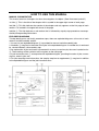
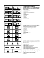
YFM660FR 5KM2-AE2 SUPPLEMENTARY SERVICE MANUAL FOREWORD This Supplementary Service Manual has been prepared to introduce new service and data for the YFM660FR. For complete service information procedures it is necessary to use this Supplementary Service Manual together with the following manual. YFM660F(P) 2002 SERVICE MANUAL: 5KM2-AE1 YFM660FR SUPPLEMENTARY SERVICE MANUAL ©2002 by Yamaha Motor Co., Ltd. First edition, June 2002 All rights reserved. Any reproduction or unauthorized use without the written permission of Yamaha Motor Co., Ltd. is expressly prohibited. EB001000 NOTICE This manual was produced by the Yamaha Motor Company primarily for use by Yamaha dealers and their qualified mechanics. It is not possible to include all the knowledge of a mechanic in one manual, so it is assumed that anyone who uses this book to perform maintenance and repairs on Yamaha machine has a basic understanding of the mechanical ideas and the procedures of machine repair. Repairs attempted by anyone without this knowledge are likely to render the machine unsafe and unfit for use. Yamaha Motor Company, Ltd. is continually striving to improve all its models. Modifications and significant changes in specifications or procedures will be forwarded to all authorized Yamaha dealers and will appear in future editions of this manual where applicable. NOTE: Designs and specifications are subject to change without notice. IMPORTANT INFORMATION Particularly important information is distinguished in this manual by the following notations. The Safety Alert Symbol means ATTENTION! BECOME ALERT! YOUR SAFETY IS INVOLVED! WARNING CAUTION: NOTE: Failure to follow WARNING instructions could result in severe injury or death to the machine operator, a bystander or a person inspecting or repairing the machine. A CAUTION indicates special precautions that must be taken to avoid damage to the machine. A NOTE provides key information to make procedures easier or clearer. EB002000 HOW TO USE THIS MANUAL MANUAL ORGANIZATION This manual consists of chapters for the main categories of subjects. (See “Illustrated symbols”) 1st title 1: This is the title of the chapter with its symbol in the upper right corner of each page. 2nd title 2: This title indicates the section of the chapter and only appears on the first page of each section. It is located in the upper left corner of the page. 3rd title 3: This title indicates a sub-section that is followed by step-by-step procedures accompanied by corresponding illustrations. EXPLODED DIAGRAMS To help identify parts and clarify procedure steps, there are exploded diagrams at the start of each removal and disassembly section. 1. An easy-to-see exploded diagram 4 is provided for removal and disassembly jobs. 2. Numbers 5 are given in the order of the jobs in the exploded diagram. A number that is enclosed by a circle indicates a disassembly step. 3. An explanation of jobs and notes is presented in an easy-to-read way by the use of symbol marks 6. The meanings of the symbol marks are given on the next page. 4. A job instruction chart 7 accompanies the exploded diagram, providing the order of jobs, names of parts, notes in jobs, etc. 5. For jobs requiring more information, the step-by-step format supplements 8 are given in addition to the exploded diagram and the job instruction chart. 1 EB003000 2 GEN INFO ILLUSTRATED SYMBOLS Illustrated symbols 1 to 0 are printed on the top right of each page and indicate the subject of each chapter. SPEC 3 4 CHK ADJ 1 General information 2 Specifications 3 Periodic checks and adjustments 4 Engine 5 Cooling system 6 Carburetion 7 Drive train 8 Chassis 9 Electrical 0 Troubleshooting ENG 5 6 COOL CARB 7 8 CHAS DRIV 9 0 – ELEC TRBL SHTG + A Illustrated symbols A to H are used to identify the specifications appearing in the text. B C D E F A Can be serviced with engine mounted B Filling fluid C Lubricant D Special tool E Torque F Wear limit, clearance G Engine speed H Ω, V, A T. R. G H I J Illustrated symbols I to N in the exploded diagrams indicate the types of lubricants and lubrication points. K G E L M M B N M LS O P LT New I Apply engine oil J Apply gear oil K Apply molybdenum disulfide oil L Apply wheel bearing grease M Apply lightweight lithium-soap-based grease N Apply molybdenum disulfide grease Illustrated symbols O to P in the exploded diagrams indicate where to apply a locking agent O and when to install a new part P. O Apply the locking agent (LOCTITE) P Replace CONTENTS GENERAL INFORMATION ..............................................................................1 SPECIAL TOOLS ......................................................................................1 SPECIFICATIONS ............................................................................................2 GENERAL SPECIFICATIONS ..................................................................2 MAINTENANCE SPECIFICATIONS .........................................................3 ENGINE ................................................................................................3 ELECTRICAL ........................................................................................3 TIGHTENING TORQUES .........................................................................4 CABLE ROUTING .....................................................................................5 PERIODIC CHECKS AND ADJUSTMENTS ..................................................12 INTRODUCTION .....................................................................................12 PERIODIC MAINTENANCE/LUBRICATION ...........................................12 SEAT, CARRIERS, FENDERS AND FUEL TANK ..................................14 FRONT CARRIER, FRONT BUMPER AND FRONT GRILL ..............14 FUEL TANK ........................................................................................15 FOOTREST BOARDS .............................................................................17 ENGINE ...................................................................................................18 CHECKING THE STARTER CABLE ..................................................18 ENGINE ..........................................................................................................19 CAMSHAFT AND CYLINDER HEAD ......................................................19 RECOIL STARTER AND AC MAGNETO ...............................................21 CHECKING THE STARTER CLUTCH ................................................23 MIDDLE GEAR ........................................................................................24 MIDDLE DRIVEN SHAFT ...................................................................24 REMOVING THE MIDDLE DRIVEN SHAFT ......................................26 INSTALLING THE MIDDLE DRIVEN SHAFT .....................................28 DRIVE TRAIN .................................................................................................30 FRONT CONSTANT VELOCITY JOINTS AND DIFFERENTIAL GEAR ...............................................................30 DISASSEMBLING THE DIFFERENTIAL GEAR .................................34 CHECKING THE DIFFERENTIAL GEAR ...........................................34 ASSEMBLING THE DIFFERENTIAL GEAR .......................................35 CHASSIS ........................................................................................................37 FRONT WHEELS AND BRAKE DISCS ..................................................37 FRONT WHEELS ................................................................................37 REAR WHEELS AND BRAKE DISC .......................................................39 REAR WHEELS ..................................................................................39 STEERING SYSTEM ..............................................................................40 TIE ROD AND STEERING KNUCKLE ................................................40 CHECKING THE STEERING KNUCKLE ............................................42 REAR KNUCKLE AND STABILIZER ......................................................43 CHECKING THE REAR KNUCKLE ....................................................44 REAR ARMS AND REAR SHOCK ABSORBER .....................................45 SPECIAL TOOLS GEN INFO GENERAL INFORMATION EB102001 SPECIAL TOOLS The following special tools are necessary for complete and accurate tune-up and assembly. Use only the appropriate special tools; this will help prevent damage caused by the use of inappropriate tools or improvised techniques. Special tools may differ by shape and part number from country to country. In such a case, two types are provided. When placing an order, refer to the list provided below to avoid any mistakes. For US and CDN P/N. YM-, YU-, YS-, YK-, ACCExcept for US and CDN P/N. 90890Tool No. Tool name/How to use Coupling gear holding tool 90890-01486 YM-01486 This tool is needed when removing or installing the coupling gear nut. –1– Illustration GENERAL SPECIFICATIONS SPEC SPECIFICATIONS GENERAL SPECIFICATIONS Item Model code: Bulb wattage × quantity: Headlight Tail/brake light Indicator lights Neutral Fuel Reverse Coolant temperature warning Park position High gear Low gear Diff-lock Standard 5KM9: (for CDN) 5KMB: (for Europe) 5KMC: (for Oceania) 12 V 30 W/30 W × 2 12 V 5 W/21 W × 1 LED × 1 LCD × 1 LED × 1 LED × 1 LED × 1 LED × 1 LED × 1 LED × 1 –2– MAINTENANCE SPECIFICATIONS SPEC MAINTENANCE SPECIFICATIONS ENGINE Item Oil pump: Oil filter type Oil pump type Tip clearance “A” or “B” Side clearance Bypass valve setting pressure Oil pressure (hot) Pressure check location Standard Foam Trochoid 0.03 ~ 0.10 mm (0.0012 ~ 0.0039 in) 0.03 ~ 0.10 mm (0.0012 ~ 0.0039 in) 441 ~ 637 kPa (4.41 ~ 6.37 kg/cm2, 62.7 ~ 90.6 psi) 65 kPa (0.65 kg/cm2, 9.2 psi) at 1,500 r/min Cylinder head Limit ------0.15 mm (0.006 in) 0.17 mm (0.007 in) ---------- ELECTRICAL Item C.D.I.: Magneto model/manufacturer Pickup coil resistance/color Rotor rotation direction sensing coil resistance/color C.D.I. unit model/manufacturer Charging system: Type Model/manufacturer Nominal output Charging coil resistance/color Standard Limit F4T46972/MITSUBISHI 459 ~ 561 Ω at 20 °C (68 °F)/ White/Red – White/Green 0.063 ~ 0.077 Ω at 20 °C (68 °F)/ Red – White/Blue F8T38671/MITSUBISHI ------- A.C. magneto generator F4T469/MITSUBISHI 14 V 21 A at 5,000 r/min 0.32 ~ 0.43 Ω at 20 °C (68 °F)/ White – White ------------- –3– ------- TIGHTENING TORQUES SPEC TIGHTENING TORQUES Engine tightening torques Part to be tightened Exhaust pipe protector Oil seal retainer Part name Bolt Screw Thread Q’ty size M6 M5 5 2 Tightening torque Nm m·kg ft·lb 11 7 1.1 0.7 8 5.1 Remarks Chassis tightening torques Part to be tightened Thread size Front wheel hub and constant velocity joint Rear wheel hub and constant velocity joint Front brake master cylinder and handlebar M20 M20 M8 –4– Tightening torque Remarks Nm m·kg ft·lb 260 260 7 26.0 26.0 0.7 190 Stake 190 Stake 5.1 LT CABLE ROUTING SPEC CABLE ROUTING 1 Fuel sender lead 2 Differential gear case and final drive gear case breather hose 3 Vacuum chamber breather hose 4 Starter motor lead 5 Wire harness 6 Gear position switch lead 7 Final drive gear case breather hose 8 Ground lead 9 Speed sensor lead 0 AC magneto lead A Carburetor breather hose B Starter cable C Fuel hose D Thermo switch 1 lead E Reverse switch lead F AC magneto coupler G Gear position switch coupler H Speed sensor coupler I Radiator fan breather hose J Rectifier/regulator lead K Water pump breather hose 1 È K 2 C A 3 4 B 5 ÉÊ E-E 6Ë D B 7 Ì E E A Í 0 9 I 8 I 5 7 2 B Ï 8 E D 7 F C H D J G 3Î C B-B A –5– D CABLE ROUTING SPEC È Fasten the final drive gear case breather hose, speed sensor lead, ground lead, gear position switch lead, AC magneto lead, wire harness, and reverse indicator light lead with a plastic locking tie. Be careful not to pinch the breather hose. É Fasten the leads in the following order: ground lead, reverse switch lead, speed sensor lead, gear position switch lead, and AC magneto lead. Ê Pass the final drive gear case breather hose through the hole in air duct assembly 3. Ë To the rear fender Ì 70 ~ 90 mm (2.8 ~ 3.5 in) Í Clamp the thermostat assembly breather hose and carburetor breather hose with the cable guide. 1 È K 2 C A 3 4 B 5 ÉÊ E-E 6Ë D B 7 Ì E E A Í 0 9 I 8 I 5 7 2 B Ï 8 E D 7 F C H D J G 3Î C B-B A –6– D CABLE ROUTING SPEC Î Pass the vacuum chamber breather hose through the plastic cover hole. Ï Insert a hook into the third hole from the bottom of the rectifier/regulator bracket, and then fasten the final drive gear case breather hose onto the hook. 1 È K 2 C A 3 4 B 5 ÉÊ E-E 6Ë D B 7 Ì E E A Í 0 9 I 8 I 5 7 2 B Ï 8 E D 7 F C H D J G 3Î C B-B A –7– D CABLE ROUTING 1 Gear position switch 2 Reverse switch 3 Crankcase breather hose 4 Select lever control cable 5 Rear brake cable 6 Front brake hose 7 Rear brake light switch lead 8 Spark plug lead 9 Fan motor breather hose 0 Fan motor lead A Brake fluid reservoir hose SPEC B Rear brake hose È Pass the rear brake cable and throttle cable through the cable guide. É Pass the rear brake light switch lead, main switch lead and auxiliary DC jack lead over the front fender. 6 5 12 7É Ì Ê 8Ë È 3 9 4 0 B A –8– Í CABLE ROUTING SPEC Ê Clamp the spark plug lead and radiator inlet hose with a plastic clip. Ë When installing the ignition coil, face the spark plug lead to the right side of the frame. Ì To the rear fender hole Í Pass the brake light switch lead on the inside of the rear brake cable and select lever control cable, and through the cable guide of the brake master cylinder cover. 6 5 12 7É Ì Ê 8Ë È 3 9 4 0 B A –9– Í SPEC CABLE ROUTING 1 Front brake hose 2 Throttle cable 3 Thermo switch 1 lead 4 Crankcase breather hose 5 Fuel sender lead 6 Differential gear case breather hose 7 Starter cable 8 Select lever control cable 9 Wire harness 0 Fan motor breather hose È Pass the thermo sensor 1 lead through the lead guide. É Pass the crankcase breather hose through the hose guide. Ê Pass the fuel sender lead through the lead guide. Ë Pass the select lever control cable through the hole of the select lever unit bracket. Ì Clamp the starter cable with a cable holder. Í Pass the throttle cable through the cable guide. 8 Í A-A Ì 8 Ë 1 A A 2 7 C B Î C 6 3 È B É 0 6 5 9 4 Ê – 10 – C-C SPEC CABLE ROUTING Î Fasten the wire harness speed sensor coupler, thermo switch 1 lead, reverse switch lead, and ground lead with a plastic locking tie. 8 Í A-A Ì 8 Ë 1 A A 2 7 C B Î C 6 3 È B É 0 6 5 9 4 Ê – 11 – C-C INTRODUCTION/PERIODIC MAINTENANCE/ LUBRICATION CHK ADJ EB300000 PERIODIC CHECKS AND ADJUSTMENTS INTRODUCTION This chapter includes all information necessary to perform recommended inspections and adjustments. These preventive maintenance procedures, if followed, will ensure more reliable vehicle operation and a longer service life. The need for costly overhaul work will be greatly reduced. This information applies to vehicles already in service as well as to new vehicles that are being prepared for sale. All service technicians should be familiar with this entire chapter. EBU00261 PERIODIC MAINTENANCE/LUBRICATION INITIAL ITEM ROUTINE Whichever comes first Valves* • Check valve clearance. • Adjust if necessary. Cooling system • Check coolant leakage. • Repair if necessary. • Replace coolant every 24 months. Spark plug • Check condition. • Adjust gap and clean. • Replace if necessary. Air filter • Clean. • Replace if necessary. Carburetor* • Check and adjust idle speed/starter operation. • Adjust if necessary. Crankcase breather system* • Check breather hose for cracks or damage. • Replace if necessary. Exhaust system* • Check for leakage. • Retighten if necessary. • Replace gasket(s) if necessary. Fuel line* • Check fuel hose for cracks or damage. • Replace if necessary. Engine oil • Replace (Warm engine before draining). Engine oil filter cartridge • Replace. Final gear oil Differential gear oil EVERY km (mile) 320 (200) 1,200 (750) 2,400 (1,500) 2,400 (1,500) 4,800 (3,000) hours 20 75 150 150 300 Every 20 ~ 40 hours (More often in wet or dusty areas.) • Check oil level/oil leakage. • Replace. Front brake* • Check operation/fluid leakage/see NOTE page 13. • Correct if necessary. Rear brake* • Check operation/fluid leakage/see NOTE page 13. • Correct if necessary. V-belt* • Check operation. • Check for cracks or damage. Wheels* • Check balance/damage/runout. • Repair if necessary. – 12 – PERIODIC MAINTENANCE/LUBRICATION CHK ADJ INITIAL ITEM ROUTINE Whichever comes first EVERY km (mile) 320 (200) 1,200 (750) 2,400 (1,500) 2,400 (1,500) 4,800 (3,000) hours 20 75 150 150 300 Wheel bearing* • Check bearing assemblies for looseness/damage. • Replace if damaged. Front and rear suspension* • Check operation. • Correct if necessary. Steering system* • Check operation/Replace if damaged. • Check toe-in/Adjust if necessary. Rear upper and lower • Lubricate.** knuckle pivots* Drive shaft universal • Lubricate.** joint* Engine mount* • Check for cracks or damage. Front and rear axle boots* • Check operation. • Replace if damaged. Stabilizer bushes* • Check for cracks or damage. Fittings and Fasteners* • Check all chassis fittings and fasteners. • Correct if necessary. * It is recommended that these items be serviced by a Yamaha dealer. ** Lithium-soap-based grease NOTE: ● Recommended brake fluid: DOT 4 ● Brake fluid replacement: 1.When disassembling the master cylinder or caliper, replace the brake fluid. Normally check the brake fluid level and add fluid as required. 2.On the inner parts of the master cylinder and caliper, replace the oil seals every two years. 3.Replace the brake hoses every four years, or if cracked or damaged. WARNING Indicates a potential hazard that could result in serious injury or death. – 13 – SEAT, CARRIERS, FENDERS AND FUEL TANK CHK ADJ SEAT, CARRIERS, FENDERS AND FUEL TANK FRONT CARRIER, FRONT BUMPER AND FRONT GRILL T. R. 1 33 Nm (3.3 m • kg, 24 ft • Ib) (8) 2 2 4 3 7 9 8 6 (6) T. R. 33 Nm (3.3 m • kg, 24 ft • Ib) LT 5 T. R. Order 1 2 3 4 5 6 7 8 9 Job name/Part name Removing the front carrier, front bumper and front grill Seat and fuel tank side panels Cap Front carrier cover Front carrier Front fender panel Engine skid plate (front) Front bumper protector Front bumper Headlight coupler Front grill Q’ty 9 Nm (0.9 m • kg, 6.5 ft • Ib) Remarks Remove the parts in the order below. Refer to “SEAT AND SIDE PANELS” in CHAPTER 3. (Manual No.: 5KM2-AE1) 2 2 1 1 1 2 1 2 1 Disconnect. For installation, reverse the removal procedure. – 14 – SEAT, CARRIERS, FENDERS AND FUEL TANK CHK ADJ FUEL TANK 1 4 2 5 8 6 10 11 7 10 9 3 9 Order Job name/Part name Removing the fuel tank Seat and side panels Q’ty Fuel tank cover 1 2 Fuel sender coupler Fuel hose 1 1 3 4 Fuel cock lever Fuel tank 1 1 – 15 – Remarks Remove the parts in the order below. Refer to “SEAT AND SIDE PANELS” in CHAPTER 3. (Manual No.: 5KM2-AE1) Refer to “HANDLEBAR COVER, FUEL TANK COVER AND FRONT FENDER” in CHAPTER 3. (Manual No.: 5KM2-AE1) Disconnect. NOTE: Before disconnecting the fuel hose, turn the fuel cock to “OFF”. NOTE: When installing the fuel tank, pass the fuel tank breather hose through the hole in the handlebar protector. SEAT, CARRIERS, FENDERS AND FUEL TANK CHK ADJ 1 4 2 5 8 6 10 11 7 10 9 3 9 Order 5 6 7 8 9 10 11 Job name/Part name Clamp Vacuum chamber breather hose Differential gear case breather hose Crankcase breather hose Plastic band Bushing Plastic cover Q’ty 1 1 1 1 3 2 1 Remarks For installation, reverse the removal procedure. – 16 – CHK ADJ FOOTREST BOARDS FOOTREST BOARDS T. R. 1 9 Nm (0.9 m • kg, 6.5 ft • Ib) (4) 1 (8) 2 (12) 3 4 (12) (8) T. R. Order 1 2 3 4 Job name/Part name Removing the footrest boards Fuel tank side panels Footrest Left footrest board Right footrest board Footrest bracket Q’ty 4 33 Nm (3.3 m • kg, 24 ft • Ib) Remarks Remove the parts in the order below. Refer to “SEAT AND SIDE PANELS” in CHAPTER 3. (Manual No.: 5KM2-AE1) 2 1 1 2 For installation, reverse the removal procedure. – 17 – CHECKING THE STARTER CABLE CHK ADJ ENGINE CHECKING THE STARTER CABLE 1.Remove: ● Seat ● Fuel tank side panel (left) 2.Check: ● Starter cable Unsmooth operation → Replace. ***************************************************** Checking steps: ● Disconnect the starter cable 1 from the carburetor body. NOTE: Do not remove the starter plunger 2 from the starter cable. ● Measure the starter plunger stroke distance a of the starter lever 3 from the fully closed to fully open positions. Starter plunger stroke distance: 15 mm (0.59 in) È Fully closed position É Fully open position ● Connect the starter cable to the carburetor. WARNING After checking the cable, turn the handlebar right and left, and make sure that the engine idling speed does not increase. ***************************************************** 3.Install: ● Fuel tank side panel (left) ● Seat – 18 – CAMSHAFT AND CYLINDER HEAD ENG ENGINE CAMSHAFT AND CYLINDER HEAD Order Job name/Part name Removing the camshaft and cylinder head Seat/front fender Fuel tank/plastic covers Q’ty Carburetors Thermostat Thermostat assembly breather hose Muffler/exhaust pipe Thermo switch lead – 19 – Remarks Remove the parts in the order below. Refer to “SEAT, CARRIERS, FENDERS AND FUEL TANK” in CHAPTER 3. (Manual No.: 5KM2-AE1) Refer to “CARBURETOR” in CHAPTER 6. (Manual No.: 5KM2-AE1) Refer to “THERMOSTAT” in CHAPTER 5. (Manual No.: 5KM2-AE1) Refer to “WATER PUMP” in CHAPTER 5. (Manual No.: 5KM2-AE1) Refer to “ENGINE REMOVAL” in CHAPTER 4. (Manual No.: 5KM2-AE1) Refer to “HOSES AND LEADS” in CHAPTER 4. (Manual No.: 5KM2-AE1) CAMSHAFT AND CYLINDER HEAD Order Job name/Part name Cylinder head cover Q’ty 1 2 3 4 5 6 7 8 9 10 11 Timing chain tensioner cap bolt Timing chain tensioner/gasket Timing chain guide (exhaust) Decompressor cam guide plate Camshaft sprocket Camshaft Thermo switch Cylinder head Cylinder head gasket Dowel pin Carburetor joint 1 1/1 1 2 1 1 1 1 1 2 1 ENG Remarks Refer to “CYLINDER HEAD COVER” in CHAPTER 4. (Manual No.: 5KM2-AE1) Refer to “REMOVING/INSTALLING THE CAMSHAFT AND CYLINDER HEAD” in CHAPTER 4. (Manual No.: 5KM2-AE1) For installation, reverse the removal procedure. – 20 – RECOIL STARTER AND AC MAGNETO ENG RECOIL STARTER AND AC MAGNETO Order Job name/Part name Removing the AC magneto Engine oil Q’ty Coolant Seat and side panels/engine side cover Left footrest board Select lever unit Water pump assembly 1 2 Recoil starter assembly AC magneto coupler 1 2 – 21 – Remarks Remove the parts in the order below. Drain. Refer to “CHANGING THE ENGINE OIL” in CHAPTER 3. (Manual No.: 5KM2-AE1) Drain. Refer to “CHANGING THE COOLANT” in CHAPTER 3. (Manual No.: 5KM2-AE1) Refer to “SEAT AND SIDE PANELS” in CHAPTER 4. (Manual No.: 5KM2-AE1) Refer to “FOOTREST BOARDS”. Refer to “SELECT LEVER UNIT AND COOLANT RESERVOIR” in CHAPTER 4. (Manual No.: 5KM2-AE1) Refer to “WATER PUMP” in CHAPTER 5. (Manual No.: 5KM2-AE1) Disconnect. RECOIL STARTER AND AC MAGNETO Order 3 4 5 6 7 8 9 10 11 12 13 14 15 Job name/Part name Starter pulley Crankcase cover (left)/gasket Dowel pin Lead holder Pickup coil Starter assembly CDI rotor Woodruff key Starter wheel gear Washer Starter idle gear shaft Bearing Starter idle gear Q’ty 1 1/1 2 1 1 1 1 1 1 1 1 1 1 ENG Remarks Refer to “REMOVING/INSTALLING THE AC MAGNETO” in CHAPTER 4. (Manual No.: 5KM2-AE1) Refer to “REMOVING/INSTALLING THE AC MAGNETO” in CHAPTER 4. (Manual No.: 5KM2-AE1) For installation, reverse the removal procedure. – 22 – RECOIL STARTER AND AC MAGNETO ENG CHECKING THE STARTER CLUTCH 1.Check: ● Starter clutch 1 Cracks/damage → Replace. ● Bolts 2 (starter clutch) Loose → Replace with new ones, and clinch the end of the bolts. NOTE: The arrow mark on the starter clutch must face inward, away from the CDI rotor. T. R. Bolts (starter clutch): 30 Nm (3.0 m • kg, 22 ft • lb) LOCTITE® ***************************************************** Checking steps: ● Install the starter wheel gear onto the starter clutch, and hold the starter clutch. NOTE: Install the starter wheel gear with the groove 1 facing the CDI rotor. ● Turn the starter wheel gear counterclockwise È to check that the starter clutch and wheel gear engage. If the starter clutch and wheel gear do not engaged, replace the starter clutch. ● Turn the starter wheel gear clockwise É to check the starter wheel gear for smooth operation. If operation is not smooth, replace the starter clutch. ***************************************************** 2.Check: ● Gear teeth (starter idle) 1 ● Gear teeth (starter wheel) 2 Burrs/clips/roughness/wear → Replace. 3.Check: ● Starter wheel gear (contacting surface) Damage/pitting/wear → Replace. – 23 – MIDDLE GEAR ENG MIDDLE GEAR MIDDLE DRIVEN SHAFT Order Job name/Part name Disassembling the middle driven shaft Crankcase separation Q’ty 1 2 3 4 Front drive shaft coupling Coupling gear Bearing housing/O-ring Shim 1 1 1/1 5 6 Middle driven pinion gear Bearing retainer 1 1 Remarks Remove the parts in the order below. Refer to “CRANKCASE” in CHAPTER 4. (Manual No.: 5KM2-AE1) – 24 – Refer to “INSTALLING/REMOVING THE MIDDLE DRIVEN SHAFT”. Refer to “MIDDLE DRIVE AND DRIVEN GEAR SHIM SELECTION”. (Manual No.: 5KM2-AE1) Refer to “REMOVING/INSTALLING THE MIDDLE DRIVEN SHAFT”. MIDDLE GEAR Order 7 8 Job name/Part name Bearing retainer Middle driven shaft Q’ty 1 1 ENG Remarks For installation, reverse the removal procedure. – 25 – MIDDLE GEAR ENG REMOVING THE MIDDLE DRIVEN SHAFT 1.Remove: ● Nut 1 ● Washer ● Front drive shaft coupling 1 2 NOTE: Use the coupling gear holding tool 2 to hold the front drive shaft coupling. Coupling gear holding tool: P/N. YM-01486, 90890-01486 2.Remove: ● Nut 1 ● Washer ● Coupling gear 2 NOTE: Use the coupling gear/middle shaft tool 3 to hold the coupling gear. Coupling gear/middle shaft tool P/N. YM-01230, 90890-01229 3.Remove: ● Bearing housing assembly 1 ***************************************************** Removal steps: ● Clean the outside of the middle driven shaft. ● Place the middle driven shaft onto a hydraulic press. CAUTION: ● ● Never directly press the shaft end with a hydraulic press, this will result in damage to the shaft thread. Install the suitable socket 2 on the shaft end to protect the thread from damage. ● Press the shaft end and remove the bearing housing. ***************************************************** – 26 – MIDDLE GEAR ENG 4.Remove: ● Bearing retainer ● Bearing ***************************************************** Removal steps: ● Place a rag 1 in the vise. ● Secure the bearing housing edge in the vise. ● Attach the bearing retainer wrench 2. Bearing retainer wrench: P/N. YM-04128, 90890-04128 CAUTION: The middle driven shaft bearing retainer has left-handed threads. To loosen the retainer, turn it clockwise. ● Remove the bearing retainer and bearing. ***************************************************** 5.Remove: ● Front drive shaft coupling ● Oil seal 1 ● Bearing retainer 2 ● Bearing NOTE: Attach the ring nut wrench 3. Ring nut wrench: P/N. YM-38404, 90890-01430 CAUTION: The middle driven shaft bearing retainer has left-handed threads. To loosen the retainer, turn it clockwise. 6.Remove: ● Middle drive shaft 1 (with bearing) – 27 – MIDDLE GEAR ENG INSTALLING THE MIDDLE DRIVEN SHAFT 1.Install: ● Bearing retainer 1 LT T. R. 80 Nm (8.0 m • kg, 58 ft • lb) NOTE: Attach the ring nut wrench 2. Ring nut wrench: P/N. YM-38404, 90890-01430 CAUTION: The middle driven shaft bearing retainer has left-handed threads. To tighten the retainer, turn it counterclockwise. 2.Install: ● Bearing retainer 1 LT ***************************************************** Installation steps: ● Place a rag 2 in the vise. ● Secure the bearing housing edge in the vise. ● Attach the bearing retainer wrench 3. Bearing retainer wrench: P/N. YM-04128, 90890-04128 ● Tighten the bearing retainer. CAUTION: The middle driven shaft bearing retainer has left-handed threads. To tighten the retainer, turn it counterclockwise. T. R. Bearing retainer: 110 Nm (11.0 m • kg, 80 ft • lb) ***************************************************** 3.Install: ● Shims 1 ● Bearing housing NOTE: Install the shims so that the tabs are positioned as shown in the illustration. – 28 – MIDDLE GEAR ENG 4.Install: ● Front drive shaft coupling ● Washer 97 Nm (9.7 m • kg, 70 ft • lb) ● Nut 1 LT T. R. 1 NOTE: Use the coupling gear holding tool 2 to hold the front drive shaft coupling. 2 Coupling gear holding tool: P/N. YM-01486, 90890-01486 – 29 – FRONT CONSTANT VELOCITY JOINTS AND DIFFERENTIAL GEAR DRIV DRIVE TRAIN FRONT CONSTANT VELOCITY JOINTS AND DIFFERENTIAL GEAR 1 LS 6 4 5 3 LS 2 LS LS T. R. 55 Nm (5.5 m • kg, 40 ft • Ib) 1 Order Job name/Part name Removing the front constant velocity joint and differential gear Engine skid plate (front) Front fender Q’ty Refer to “SEAT, CARRIERS, FENDERS AND FUEL TANK” in CHAPTER 3. (Manual No.: 5KM2-AE1) Drain. Refer to “STEERING SYSTEM” in CHAPTER 8. (Manual No.: 5KM2-AE1) Refer to “FRONT ARMS AND FRONT SHOCK ABSORBER” in CHAPTER 8. (Manual No.: 5KM2-AE1) Refer to “FRONT AND REAR BRAKES” in CHAPTER 8. (Manual No.: 5KM2-AE1) Differential gear oil Steering knuckle Front arms (lower) Brake master cylinder cover 1 2 Constant velocity joint Gear motor coupler/on-command fourwheel drive switch and differential gear lock switch coupler Remarks Remove the parts in the order below. 2 1/1 – 30 – Disconnect. FRONT CONSTANT VELOCITY JOINTS AND DIFFERENTIAL GEAR DRIV 1 LS 6 4 5 3 LS 2 LS LS T. R. 55 Nm (5.5 m • kg, 40 ft • Ib) 1 Order 3 4 5 6 Job name/Part name Differential gear case breather hose Differential gear Compression spring Drive shaft assembly Q’ty Remarks 1 Disconnect. 1 1 1 For installation, reverse the removal procedure. – 31 – FRONT CONSTANT VELOCITY JOINTS AND DIFFERENTIAL GEAR Order Q’ty 1 Job name/Part name Disassembling the differential gear Gear motor/O-ring 2 Coupling gear/O-ring 1/1 3 4 5 6 7 8 Sttoper bolt/shaft Shift fork sliding gear Shift fork Differential gear case cover Drive clutch Shim (left) 1/1 1 1 1 1 1/1 – 32 – DRIV Remarks Remove the parts in the order below. NOTE: Do not disassemble the gear motor or remove the pinion gear. Refer to “DISASSEMBLING/ASSEMBLING THE DIFFERENTIAL GEAR”. FRONT CONSTANT VELOCITY JOINTS AND DIFFERENTIAL GEAR Order 9 0 A B C Job name/Part name Differential gear assembly Shim (right) Circlip/bearing Drive pinion gear Differential gear case Q’ty 1 DRIV Remarks 1/1 1 1 For assembly, reverse the disassembly procedure. – 33 – FRONT CONSTANT VELOCITY JOINTS AND DIFFERENTIAL GEAR 1 DRIV DISASSEMBLING THE DIFFERENTIAL GEAR 1.Remove: ● Coupling gear Use a coupling gear holding tool 1. Coupling gear holding tool: P/N. YM-01486, 90890-01486 CHECKING THE DIFFERENTIAL GEAR 1.Check: ● Gear teeth Pitting/galling/wear → Replace drive pinion gear and ring gear as a set. ● Bearing Pitting/damage → Replace. ● Oil seal ● O-ring Damage → Replace. 2.Check: ● Drive shaft splines ● Front drive gear splines Wear/damage → Replace. ● Spring Fatigue → Replace. Move the spring up and down. 3.Check: ● Dust boots Cracks/damage → Replace the front drive shaft assembly. 4.Check: ● Front drive shaft Bends → Replace the front drive shaft assembly. WARNING Do not attempt to straighten a bent shaft; this may dangerously weaken the shaft. – 34 – FRONT CONSTANT VELOCITY JOINTS AND DIFFERENTIAL GEAR DRIV 5.Check: ● Front drive shaft assembly operation Unsmooth operation → Replace the front drive shaft assembly. ASSEMBLING THE DIFFERENTIAL GEAR 1.Measure: ● Gear lash Refer to “MEASURING AND ADJUSTING THE DIFFERENTIAL GEAR LASH”. in CHAPTER 7. (Manual No.: 5KM2-AE1) 2.Install: ● Gear motor ***************************************************** Installation steps: ● Slide the shift fork sliding gear 1, which is installed to the differential gear, to the left to put it into the 2WD mode. ● Connect two C size batteries to the gear motor terminal 2 to operate the pinion gear 3. Operate the pinion gear until the paint mark 4 on the gear is aligned with the paint mark 5 on the gear motor case. CAUTION: Do not use a 12 V battery to operate the pinion gear. 8 mm bolts 6 into the gear motor 7 and use them as a guide to set the motor on the differential gear assembly 8 so that the shift fork sliding gear 9 does not move. ● Insert CAUTION: If the position of the shift fork sliding gear is moved, the position of the differential gear and the indicator light display may differ, and the 2WD or differential lock mode may not be activated. ● Remove the 8 mm bolts, and then install the motor with the gear motor bolts. T. Bolts (gear motor) 13 Nm (1.3 m • kg, 9.4 ft • lb) R. ***************************************************** – 35 – FRONT CONSTANT VELOCITY JOINTS AND DIFFERENTIAL GEAR 1 DRIV 3.Install: ● Coupling gear ● O-ring ● Washer ● Nut 62 Nm (6.2 m • kg, 45 ft • lb) Use a coupling gear holding tool 1. LT T. R. Coupling gear holding tool: P/N. YM-01486, 90890-01486 4.Check: ● Differential gear operation Unsmooth operation → Replace the differential gear assembly. Insert the double off-set joint into the differential gear, and then turn the gear back and forth. – 36 – FRONT WHEELS AND BRAKE DISCS CHAS CHASSIS FRONT WHEELS AND BRAKE DISCS FRONT WHEELS T. R. 30 Nm (3.0 m • kg, 22 ft • Ib) LT LT T. R. 260 Nm (26.0 m • kg, 190 ft • lb) 3 New 1 2 6 4 5 T. R. 30 Nm (3.0 m • kg, 22 ft • Ib) T. R. Order Job name/Part name Removing the front wheel Q’ty 55 Nm (5.5 m • kg, 40 ft • Ib) Remarks Remove the parts in the order below. Place the machine on a level surface. WARNING Securely support the machine so there is no danger of it falling over. 1 Front wheel 1 2 3 Wheel cap Axle nut 1 1 – 37 – Refer to “INSTALLING THE FRONT WHEEL” in CHAPTER 8. (Manual No.: 5KM2-AE1) Refer to “INSTALLING THE FRONT WHEEL HUB” in CHAPTER 8. (Manual No.: 5KM2-AE1) FRONT WHEELS AND BRAKE DISCS CHAS T. R. 30 Nm (3.0 m • kg, 22 ft • Ib) LT LT T. R. 260 Nm (26.0 m • kg, 190 ft • lb) 3 New 1 2 6 4 5 T. R. 30 Nm (3.0 m • kg, 22 ft • Ib) T. R. Order 4 5 6 Job name/Part name Brake caliper assembly Front wheel hub Brake disc Q’ty 1 55 Nm (5.5 m • kg, 40 ft • Ib) Remarks NOTE: Do not squeeze the brake lever when the brake caliper is off of the brake disc as the brake pads will be forced shut. 1 1 For installation, reverse the removal procedure. – 38 – REAR WHEELS AND BRAKE DISC CHAS REAR WHEELS AND BRAKE DISC REAR WHEELS T. R. 260 Nm (26.0 m • kg, 190 ft • lb) T. R. 55 Nm (5.5 m • kg, 40 ft • Ib) 3 New 2 4 1 Order Job name/Part name Removing the rear wheel Q’ty Remarks Remove the parts in the order below. Place the machine on a level surface. WARNING Securely support the machine so there is no danger of it falling over. 1 Rear wheel 1 2 3 Wheel cap Axle nut 1 1 4 Rear wheel hub 1 Refer to “INSTALLING THE REAR WHEEL” in CHAPTER 8. (Manual No.: 5KM2-AE1) Refer to “INSTALLING THE REAR WHEEL HUB” in CHAPTER 8. (Manual No.: 5KM2-AE1) For installation, reverse the removal procedure. – 39 – STEERING SYSTEM CHAS STEERING SYSTEM TIE ROD AND STEERING KNUCKLE New T. R. 25 Nm (2.5 m • kg, 18 ft • Ib) 6 T. R. 10 Nm (1.0 m • kg, 7.2 ft • Ib) 1 LS T. R. 25 Nm (2.5 m • kg, 18 ft • Ib) 4 New 2 7 3 4 5 New T . R. Job name/Part name Removing the tie rod and steering knuckle Front fender 1 Front wheel/brake disc Tie rod 2 3 4 5 Brake disc guard Front protector Bolt/washer/nut Nut R. R. 25 Nm (2.5 m • kg, 18 ft • Ib) T. T. Order New 48 Nm (4.8 m • kg, 35 ft • Ib) Q’ty 1 1 1 1/1/1 1 – 40 – 7 Nm (0.7 m • kg, 5.1 ft • Ib) Remarks Remove the parts in the order below. Refer to “SEAT, CARRIERS, FENDERS AND FUEL TANK” in CHAPTER 3. (Manual No.: 5KM2-AE1) Refer to “FRONT WHEELS”. Refer to “INSTALLING THE TIE ROD” in CHAPTER 8. (Manual No.: 5KM2-AE1) STEERING SYSTEM CHAS New T. R. 25 Nm (2.5 m • kg, 18 ft • Ib) 6 T. R. 10 Nm (1.0 m • kg, 7.2 ft • Ib) 1 LS T. R. 25 Nm (2.5 m • kg, 18 ft • Ib) 4 New 2 7 3 4 5 New T . R. Job name/Part name Brake hose holder bolt Steering knuckle R. R. 25 Nm (2.5 m • kg, 18 ft • Ib) T. T. Order 6 7 New 48 Nm (4.8 m • kg, 35 ft • Ib) 7 Nm (0.7 m • kg, 5.1 ft • Ib) Q’ty Remarks 1 1 Refer to “REMOVING THE STEERING KNUCKLE” in CHAPTER 8. (Manual No.: 5KM2-AE1) For installation, reverse the removal procedure. – 41 – STEERING SYSTEM CHAS CHECKING THE STEERING KNUCKLE 1.Check: ● Steering knuckle Damage/pitting → Replace. 2 1 2.Check: ● Front wheel bearings Bearings allow play in the wheel hubs or unsmooth wheel operation → Replace. ● Oil seals Damage → Replace. ***************************************************** Replacement steps: ● Clean the outside of the steering knuckle. ● Remove the circlip 1. ● Drive out the bearing 2. WARNING Eye protection is recommended when using striking tools. ● Apply lithium-soap-based grease to the bear- ing. ● Install the new bearing. CAUTION: Do not strike the center race or balls of the bearing. Contact should be made only with the outer race. ● Install a new circlip. ***************************************************** – 42 – CHAS REAR KNUCKLE AND STABILIZER REAR KNUCKLE AND STABILIZER 7 T. 6 R. 30 Nm (3.0 m • kg, 22 ft • Ib) 8 5 7 8 9 5 T. R. 48 Nm (4.8 m • kg, 35 ft • Ib) T. R. 45 Nm (4.5 m • kg, 32 ft • Ib) T. R. 48 Nm (4.8 m • kg, 35 ft • Ib) 3 LS 4 3 1 3 LS Order 1 2 3 4 5 6 7 8 9 2 4 3 Job name/Part name Removing the rear knuckle and stabilizer Rear wheel hubs Rear protector Rear knuckle Spacer cover Spacer Stabilizer joint Brake hose holder Stabilizer holder Bushing Stabilizer Q’ty Remarks Remove the parts in the order below. Refer to “REAR WHEELS AND BRAKE DISC”. 1 1 4 2 2 1 2 2 1 For installation, reverse the removal procedure. – 43 – REAR KNUCKLE AND STABILIZER CHAS CHECKING THE REAR KNUCKLE 1.Check: ● Rear knuckle Damage/pitting → Replace. 2.Check: ● Rear wheel bearings Bearings allow play in the wheel hubs or unsmooth wheel operation → Replace. ● Oil seals Damage → Replace. 2 1 ***************************************************** Replacement steps: ● Clean the outside of the rear knuckle. ● Remove the circlip 1. ● Drive out the bearing 2. WARNING Eye protection is recommended when using striking tools. ● Apply lithium-soap-based grease to the bearing. ● Install the new bearing. CAUTION: Do not strike the center race or balls of the bearing. Contact should be made only with the outer race. ● Install a new circlip. ***************************************************** – 44 – REAR ARMS AND REAR SHOCK ABSORBER CHAS REAR ARMS AND REAR SHOCK ABSORBER T. 3 R. T. R. 45 Nm (4.5 m • kg, 32 ft • Ib) 45 Nm (4.5 m • kg, 32 ft • Ib) 1 1 1 5 1 5 2 2 5 5 T. R. 6 4 6 3 3 T. R. Order 1 2 3 4 5 6 45 Nm (4.5 m • kg, 32 ft • Ib) Job name/Part name Removing the rear arms and rear shock absorber Rear protector/rear knuckle/stabilizer Q’ty Nut/bolt Rear arm (upper)/bushing/washer Nut/bolt Rear shock absorber Nut/bolt Rear arm (lower)/bushing 2/2 1/2/1 2/2 1 2/2 1/2 45 Nm (4.5 m • kg, 32 ft • Ib) Remarks Remove the parts in the order below. Refer to “REAR KNUCKLE AND STABILIZER”. For installation, reverse the removal procedure. – 45 – YAMAHA MOTOR CO., LTD. 2500 SHINGAI IWATA SHIZUOKA JAPAN