1
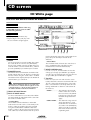
PROFESSIONAL AUDIO WORKSTATION
Owner’s Manual
Keep This Manual For Future Reference.
E
FCC INFORMATION (U.S.A.)
1. IMPORTANT NOTICE: DO NOT MODIFY THIS UNIT! This product, when installed as indicated in the instructions contained in this manual, meets FCC
requirements. Modifications not expressly approved by Yamaha may void your authority, granted by the FCC, to use the product.
2. IMPORTANT: When connecting this product to accessories and/or another product use only high quality shielded cables. Cable/s supplied with this product MUST
be used. Follow all installation instructions. Failure to follow instructions could void your FCC authorization to use this product in the USA.
3. NOTE: This product has been tested and found to comply with the requirements listed in FCC Regulations, Part 15 for Class “B” digital devices. Compliance with
these requirements provides a reasonable level of assurance that your use of this product in a residential environment will not result in harmful interference with
other electronic devices. This equipment generates/uses radio frequencies and, if not installed and used according to the instructions found in the users manual, may
cause interference harmful to the operation of other electronic devices. Compliance with FCC regulations does not guarantee that interference will not occur in all
installations. If this product is found to be the source of interference, which can be determined by turning the unit “OFF” and “ON”, please try to eliminate the
problem by using one of the following measures: Relocate either this product or the device that is being affected by the interference. Utilize power outlets that are on
different branch (circuit breaker or fuse) circuits or install AC line filter/s. In the case of radio or TV interference, relocate/reorient the antenna. If the antenna lead-in
is 300 ohm ribbon lead, change the lead-in to coaxial type cable. If these corrective measures do not produce satisfactory results, please contact the local retailer
authorized to distribute this type of product. If you can not locate the appropriate retailer, please contact Yamaha Corporation of America, Electronic Service
Division, 6600 Orangethorpe Ave, Buena Park, CA 90620
The above statements apply ONLY to those products distributed by Yamaha Corporation of America or its subsidiaries.
ADVARSEL!
Lithiumbatteri—Eksplosionsfare ved fejlagtig
håndtering. Udskiftning må kun ske med batteri
af samme fabrikat og type. Levér det brugte
batteri tilbage til leverandoren.
VARNING
Explosionsfara vid felaktigt batteribyte. Använd
samma batterityp eller en ekvivalent typ som
rekommenderas av apparattillverkaren.
Kassera använt batteri enligt fabrikantens
instruktion.
VAROITUS
Paristo voi räjähtää, jos se on virheellisesti
asennettu. Vaihda paristo ainoastaan
laitevalmistajan suosittelemaan tyyppiin. Hävitä
käytetty paristo valmistajan ohjeiden
mukaisesti.
WARNING: THIS APPARATUS MUST BE EARTHED
IMPORTANT
THE WIRES IN THIS MAINS LEAD ARE COLOURED IN
ACCORDANCE WITH THE FOLLOWING CODE:
GREEN-AND-YELLOW :
EARTH
BLUE :
NEUTRAL
BROWN :
LIVE
As the colours of the wires in the mains lead of this apparatus may
not correspond with the coloured markings identifying the terminals in
your plug, proceed as follows:
The wire which is coloured GREEN and YELLOW must be
connected to the terminal in the plug which is marked by the letter E
or by the safety earth symbol
or coloured GREEN and YELLOW.
The wire which is coloured BLUE must be connected to the terminal
which is marked with the letter N or coloured BLACK.
The wire which is coloured BROWN must be connected to the
terminal which is marked with the letter L or coloured RED.
* This applies only to products distributed by YAMAHA KEMBLE
MUSIC (U.K.) LTD.
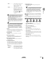
• Explanation of Graphical Symbols
CAUTION
RISK OF ELECTRIC SHOCK
DO NOT OPEN
CAUTION: TO REDUCE THE RISK OF
ELECTRIC SHOCK, DO NOT REMOVE
COVER (OR BACK). NO USER-SERVICEABLE
PARTS INSIDE. REFER SERVICING TO
QUALIFIED SERVICE PERSONNEL.
The above warning is located on the
rear of the unit.
The lightning flash with arrowhead symbol
within an equilateral triangle is intended to
alert the user to the presence of uninsulated
“dangerous voltage” within the product’s
enclosure that may be of sufficient magnitude to constitute a risk of electric shock to
persons.
The exclamation point within an equilateral triangle is intended to alert the user to
the presence of important operating and
maintenance (servicing) instructions in the
literature accompanying the product.
NEDERLAND
THE NETHERLANDS
● Dit apparaat bevat een lithium batterij voor geheugen
back-up.
● This apparatus contains a lithium battery for memory
back-up.
● Raadpleeg uw leverancier over de verwijdering van de
batterij op het moment dat u het apparaat ann het einde
van de levensduur afdankt of de volgende Yamaha Service
Afdeiing:
Yamaha Music Nederland Service Afdeiing
Kanaalweg 18-G, 3526 KL UTRECHT
Tel. 030-2828425
● For the removal of the battery at the moment of the
disposal at the end of the service life please consult your
retailer or Yamaha Service Center as follows:
Yamaha Music Nederland Service Center
Address: Kanaalweg 18-G, 3526 KL
UTRECHT
Tel: 030-2828425
● Gooi de batterij niet weg, maar lever hem in als KCA.
● Do not throw away the battery. Instead, hand it in as small
chemical waste.
Important
Important
Read the following before operating the AW2816
• If lightning begins to occur, turn off the power
switch of the unit as soon as possible, and unplug
the power cable plug from the electrical outlet.
■ Warnings
• If there is a possibility of lightning, do not touch
the power cable plug if it is still connected. Doing
so may be an electrical shock hazard.
• Do not place a container with liquid or small
metal objects on top of this unit. Liquid or metal
objects inside this unit are a fire and electrical
shock hazard.
• Do not allow water to enter this unit or allow the
unit to become wet. Fire or electrical shock may
result.
• Connect this unit’s power cord only to an AC outlet of the type stated in this Owner’s Manual or as
marked on the unit. Failure to do so is a fire and
electrical shock hazard.
• Do not scratch, bend, twist, pull, or heat the
power cord. A damaged power cord is a fire and
electrical shock hazard.
• Do not place heavy objects, including this unit, on
top of the power cord. A damaged power cord is a
fire and electrical shock hazard. In particular, be
careful not to place heavy objects on a power cord
covered by a carpet.
• To avoid possible electrical shock, do not install
an I/O card, hard disk, or CD-RW drive in the unit
while the power cable is connected to the AC outlet.
• Use the ground connector on the rear panel to
securely ground the device. If the device is not
grounded, you may suffer a dangerous electrical
shock.
• If you notice any abnormality, such as smoke,
odor, or noise, or if a foreign object or liquid gets
inside the unit, turn it off immediately. Remove the
power cord from the AC outlet. Consult your
dealer for repair. Using the unit in this condition is
a fire and electrical shock hazard.
• Should this unit be dropped or the cabinet be
damaged, turn the power switch off, remove the
power plug from the AC outlet, and contact your
dealer. If you continue using the unit without
heeding this instruction, fire or electrical shock
may result.
• If the power cord is damaged (i.e., cut or a bare
wire is exposed), ask your dealer for a replacement. Using the unit with a damaged power cord
is a fire and electrical shock hazard.
• Do not modify the unit. Doing so is a fire and electrical shock hazard.
• Do not apply force to, disassemble, or modify the
I/O card, the PC board of the hard disk, or the connectors on the unit. Otherwise, malfunction, fire,
or electrical shock may result.
iv
■ Cautions
• This unit has ventilation holes at the bottom to prevent the internal temperature rising too high. Do
not block them. Blocked ventilation holes are a
fire hazard.
• Hold the power cord plug when disconnecting it
from an AC outlet. Never pull the cord. A damaged power cord is a potential fire and electrical
shock hazard.
• Do not touch the power plug with wet hands.
Doing so is a potential electrical shock hazard.
• Always touch a well-grounded metal surface or
the like to fully discharge any static electric charge
on your body and clothing before handling an I/O
card or hard disk.
Neglecting this precaution can cause damage to
the unit from static electricity.
• Be careful not to touch the leads (metal feet) on
the rear side when handling an I/O card or hard
disk. Touching the leads can cause contact defects.
• Use only the included power supply cable for this
unit. Using other types may be a fire hazard.
■ Operating Notes
• The digital circuits of this unit may induce a slight
noise into nearby radios and TVs. If noise occurs,
relocate the affected equipment.
• Using a mobile telephone near this unit may
induce noise. If noise occurs, use the telephone
away from the unit.
• XLR-type connectors are wired as follows:
pin 1: ground, pin 2: hot (+), and pin 3: cold (–).
• Insert TRS phone jacks are wired as follows:
sleeve: ground, tip: send, and ring: return.
• If the message “LOW BATTERY” appears when
you turn on this unit, contact your dealer as soon
as possible about replacing the internal data
backup battery.
We recommend that you save the data on CD-RW
drive or external SCSI device before replacing the
battery.
• The performance of components with moving
contacts, such switches, rotary controls, faders,
and connectors, deteriorates over time. The rate of
deterioration depends on the operating environment and is unavoidable. Consult your dealer
about replacing defective components.
Handling the CD-R/RW media
Please observe the following points when handling
the disk.
Failure to do so may cause problems such as the
recorded data being lost, the drive to malfunction, or
the printed label to become blurred.
• Do not place the disk in locations of direct sunlight, high temperature, or high humidity.
• Do not touch either surface of the disk.
• Hold the disk at the edges. Gently wipe dust or
dirt off of the recording surface of the disk.
• Always touch a well-grounded metal surface or
the like to fully discharge any static electric charge
on your body and clothing before starting to work
on this equipment.
• Take extreme care to avoid touching any terminals
or board surface parts.
• In order to protect the electronic circuits of the I/O
card, hard disk, CD-RW drive, etc. from damage
due to static electricity, when handling any of this
equipment, take the most extreme care to avoid
touching IC leads or other electronic parts.
• Do not bend or drop the disk.
• Be careful not to drop any screws into the main
unit. If you switch the power on with a dropped
screw still in the main unit, the main unit may
malfunction or break down. If a dropped screw
can not be retrieved, consult your Yamaha dealer.
• Use an air duster or cleaner to remove dust. Vigorously rubbing the surface of the disk with a dry
cloth may scratch the disk.
• If the hard disk or CD-RW drive breaks down, contact the store where you purchased that equipment.
• Do not wipe the disk with chemicals or detergents.
• Do not write on the disk or affix labels to it.
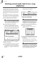
Storing produced data
Produced data can be lost due to breakdown or mistaken operation. We recommend that you store all
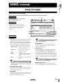
important data on CD-R or CD-RW disks or other
external storage medium.
Except for duplication for personal use or when there
is no copyright problem, the duplication or transfer of
commercially sold music/sound data without the permission of the copyright holder is prohibited. When
using this equipment, please consult with a copyright
specialist.
■ Warning
Responsibility for loss of data,
etc.
• Yamaha will accept no responsibility for any damages (including consequential or incidental)
incurred by the customer or any third party as a
result of loss or impairment of the data stored on
the CD-R media, regardless of whether such loss
could have been or actually was foreseen by
Yamaha.
• Nor does Yamaha guarantee the media against any
defect that may render it unusable.
Cautions for handling optional
equipment
• For inquiries concerning I/O card, hard disk, or
CD-RW drive handling, please consult your
Yamaha dealer.
• Always switch off the power for the main unit and
all peripherals, unplug the power cord for the
main unit from the outlet, then disconnect the
cables connecting the main unit with the peripherals before starting installation work.
The Yamaha Professional Audio Workstation is
designed to be used professionally and responsibly by
recording industry professionals. The reproduction,
distribution, or, in some instances, the public performance, of all or a portion of a sound recording or
musical composition protected by copyright, without
having obtained a proper license from the relevant
copyright holders, may constitute copyright infringement and may otherwise violate copyright laws and
other laws. In addition, laws (such as the Audio Home
Recording Act and the Digital Millennium Copyright
Act in USA) contain certain restrictions and requirements that may apply to your use of works protected
by copyright and related information and data that
may accompany such works. Violation of such laws
may result in civil remedies and, in some cases, criminal liability.
Because violations of copyright laws may be serious
offenses, you should consult a lawyer familiar with
the law of copyright, including all laws that may be
applicable to your use of the Workstation (such as the
Audio Home Recording Act and the Digital Millennium Copyright Act in USA), if you have any questions regarding your intended use of all or parts of
sound recordings or musical compositions protected
by copyright.
• Wear thick gloves when working on this equipment to avoid cutting your hands on metal fittings
or the like on the main unit, I/O card, hard disk, or
CD-RW drive.
v
Table of contents
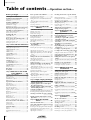
Table of contents —Operation section—
Before you begin .....................1
Checking the included items ...................1
Installing an internal hard disk ................2
About the internal hard disk..........................2
Installation ....................................................2
Installing a CD-RW drive.........................4
About the CD-RW drives ..............................4
CD-RW drive settings ...................................4
Installation procedure ...................................5
Removing the transport protection pad...7
Manual eject (emergency disc removal) .......7
Attaching an external SCSI device...........8
About external SCSI devices .........................8
Connection procedure ..................................8
Installing I/O card .................................10
About I/O cards ..........................................10
Installation procedure .................................10
Please observe the following points.......11
Turning the power on .................................11
Setting the internal clock ............................11
Turning the power off .................................12
Chapter1 Parts and their functions13
Top panel...............................................13
Analog input/output section........................13
WORK NAVIGATE section .........................14
UNIT section ..............................................14
MIXER section.............................................14
FADER MODE section................................15
MIXING LAYER section ..............................15
Fader section ..............................................16
Display section ...........................................17
REC TRACK SELECT section .......................18
RECORDER section ....................................18
AUTOMATION section ..............................19
SCENE MEMORY section ...........................19
CURSOR/JOG&SHUTTLE section...............19
LOCATE section..........................................20
Transport section ........................................21
Rear panel..............................................22
Front panel ............................................24
Chapter2 Welcome to the world
of the AW2816 ..........25
Features of the AW2816........................25
Mixer section ..............................................25
Recorder section .........................................25
CD-RW drive (option).................................26
Other features .............................................26
Signal flow within the AW2816.............27
Input patch .................................................27
Input channels 1–8 .....................................28
Return channels 1/2....................................29
Recorder input patch ..................................29
Monitor channels 1–16...............................30
Digital cascade connection.........................30
Oscillator ....................................................30
Stereo output channel.................................31
Buses 1–8 ...................................................31
AUX buses 1–6 ...........................................31
Output patch ..............................................32
Internal effects 1/2 ......................................32
Monitor output/headphone output..............32
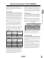
The track structure of the AW2816.......33
Audio tracks................................................33
Virtual tracks...............................................33
The stereo track ..........................................33
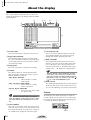
About the display...................................34
Cursor .........................................................34
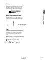
Buttons........................................................35
Knobs/faders/numerical boxes ....................35
Tabs ............................................................35
vi
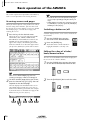
Basic operation of the AW2816 ............36
Accessing screens and pages ......................36
Switching a button on/off............................36
Editing the value of a fader/knob/numerical
box ............................................................36
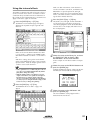
Using the additional function buttons .........37
Inputting text...............................................37
Selecting a channel.....................................38
Chapter3 Let’s record on the
AW2816 .................... 41
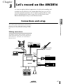
Connections and setup ..........................41
Making connections ...................................41
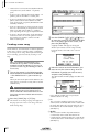
Creating a new song ...................................42
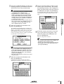
Word clock settings ....................................44
Recording the first track ........................46
Setting the input level .................................46
Pairing two channels...................................47
Patching input signals to recorder inputs ....48
Adjusting the monitor level.........................50
Recording ...................................................51
Recording additional tracks
(Overdubbing)......................................52
Setting the input level .................................52
Patching the input signal to the recorder input
.........................52
Adjusting the monitor level.........................54
Applying the equalizer to the input signal...54
Applying the dynamics processor to the input
signal.........................................................55
Recording ...................................................57
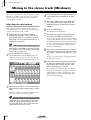
Mixing to the stereo track (Mixdown) ...58
Adjusting the mix balance ..........................58
Using the internal effects.............................59
Recording on the stereo track .....................60
Saving your song....................................62
Advanced techniques on the AW2816 ..63
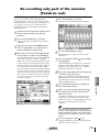
Manually re-recording only a specific area
(Manual Punch-in/out)...............................63
Automatically re-recording only a specific area
(Auto Punch-in/out) ...................................64
Switching virtual tracks...............................66
Operating multiple faders together
(Fader Groups)...........................................67
Operating multiple [ON] keys together
(Mute Groups) ...........................................68
Using the Solo function ..............................69
Chapter4 Input/output patching71
Assigning signals to input channels/return
channels (Input Patch)..........................71
Assigning signals to the recorder inputs
(Recorder Input Patch) .........................73
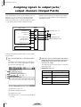
Assigning signals to output jacks/output
channels (Output Patch) ......................74
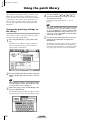
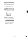
Using the patch library ..........................76
Storing the patching settings to the library ..76
Recalling patching settings from the library 77
Inserting an external effect into a channel
.......................78
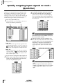
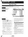
Quickly assigning input signals to tracks
(Quick Rec) ..........................................80
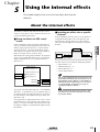
Chapter5 Using the internal
effects ....................... 83
About the internal effects ......................83
Using AUX send/return to apply an effect 84
Check the patching.....................................84
Recalling an effect program from the library84
Switching between pre-fader/post-fader......86
Adjusting the return level............................87
Adjusting the send level..............................87
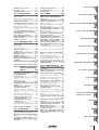
Table of contents
Inserting an effect into a specific channel
...................... 88
Change the patching.................................. 88
Inserting the effect into a channel .............. 88
Recalling an effect program ....................... 89
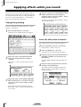
Applying effects while you record ........ 90
Change the patching.................................. 90
Insert the effect into a channel ................... 90
Start recording............................................ 91
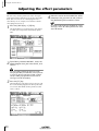
Adjusting the effect parameters ............ 92
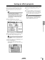
Saving an effect program ...................... 93
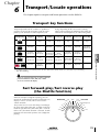
Chapter6 Transport/Locate
operations................. 95
Transport key functions ........................ 95
Fast forward-play/Fast reverse-play
(the Shuttle function)........................... 95
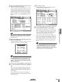
Searching for a point while you listen
(the Nudge function) ........................... 96
Searching for a point while viewing the
waveform............................................. 97
Rewinding for a specific distance
(Rollback) ............................................ 98
Repeatedly playing a specified region
(A-B Repeat) ........................................ 99
Locating to a specified point............... 100
Locating to the zero location of the counter
.................... 101
Setting the relative time zero location...... 101
Using various locate points to locate.. 102
Using markers to locate ...................... 103
Editing the location of a locate point or
marker ............................................... 104
The relation between the Start point and time
code ....................................................... 105
Deleting a locate point/marker........... 106
Deleting from within the screen............... 106
Deleting by using key operations............. 106
Chapter7 Editing tracks and
virtual tracks........... 107
Editing tracks and virtual tracks.......... 107
Tracks, parts, and regions ................... 108
Naming a track or region.................... 109
Editing a virtual track name ..................... 109
Editing a region name .............................. 110
Editing the audio data of tracks 1–16 . 111
Editing entire Tracks................................. 111
Editing by Part.......................................... 113
Editing by Region..................................... 114
Editing the audio data of virtual tracks
1–8..................................................... 116
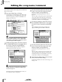
Editing commands............................... 118
Commands and parameters of the TRACK
menu ...................................................... 118
Commands and parameters of the PART
menu ...................................................... 121
Commands and parameters of the REGION
menu ...................................................... 125
Chapter8 Scene memory
operations............... 127
About scene memories........................ 127
Parameters included in a scene................ 127
About scene numbers .............................. 127
Storing a scene.................................... 128
Storing a scene by operations in the screen 128
Storing a scene by key operations............ 128
Recalling a scene................................. 129
Recalling a scene by operations in the screen
...................... 129
Recalling a scene by key operations ........ 129
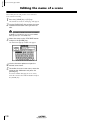
Editing the name of a scene ................ 130
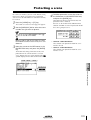
Protecting a scene............................... 131
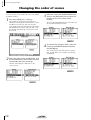
Changing the order of scenes ............. 132
Setting the mastering mode ................ 181
Executing mastering............................ 182
Finalizing a disc .................................. 185
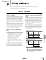
Chapter9 Using automix .........133
Chapter13 MIDI....................... 187
About automix .................................... 133
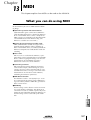
What you can do using MIDI.............. 187
MIDI connectors and the TO HOST
connector .......................................... 188
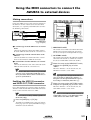
Using the MIDI connectors to connect the
AW2816 to external devices ............. 189
What is automix? ......................................133
What can be recorded in automix?...........133
How the automix is related to the song ....133
Creating a new automix...................... 134
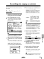
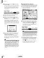
Recording and playing an automix ..... 135
Recording fader operations in the automix135
Playing back the automix .........................136
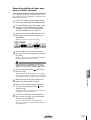
Recording additional fader operations of other
channels..................................................137
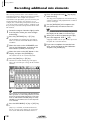
Recording additional mix elements .... 138
Re-recording only part of the automix
(Punch-in/out) ................................... 139
Re-recording fader operations ............ 141
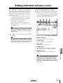
Editing individual automix events ....... 143
Storing an automix.............................. 145
Recalling an automix .......................... 146
Chapter10 Managing songs.....147
About songs ........................................ 147
What is a song?.........................................147
Song structure...........................................147
Song recording time..................................147
Saving the current song ...................... 148
Loading a song .................................... 149
Editing the song name/comment ........ 150
Protecting a song ................................ 151
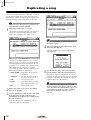
Duplicating a song .............................. 152
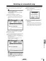
Deleting an unwanted song ................ 153
Deleting unused audio data from a song
(Optimize) ......................................... 154
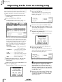
Importing mixer data from an existing song
.................... 155
Importing tracks from an existing song156
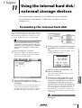
Chapter11 Using the internal hard
disk/external storage
devices ...................159
Formatting the internal hard disk ....... 159
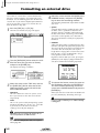
Formatting an external drive .............. 160
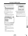
Erasing CD-RW media ........................ 161
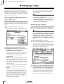
Backing up songs ................................ 162
Selecting the backup format for a removable
drive........................................................162
Executing the backup ...............................162
Making connections .................................189
Enabling the MIDI IN connector and MIDI
OUT/THRU connector ............................189
Making connections .................................190
Enabling the TO HOST connector ............190
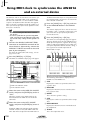
Using MTC to synchronize the AW2816
and an external device....................... 192
Using MIDI clock to synchronize the
AW2816 and an external device ....... 194
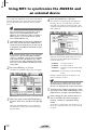
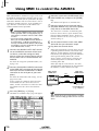
Using MMC to control the AW2816... 196
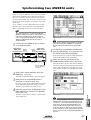
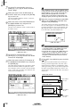
Synchronizing two AW2816 units ...... 197
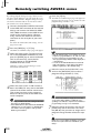
Remotely switching AW2816 scenes .. 200
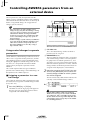
Controlling AW2816 parameters from an
external device .................................. 202
Using control changes to operate parameters
.......................202
Using system exclusive to operate parameters
.......................204
Remotely controlling an external MIDI
device ................................................ 206
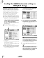
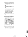
Sending the AW2816’s internal settings via
MIDI (Bulk Dump)............................. 212
Storing channel settings in a library ..........218
Recalling channel settings from a library ..219
Editing the title of a channel library ..........219
2
Let’s record on the AW2816
3
Input/output patching
4
Using the internal effects
5
Transport/Locate operations
6
Editing tracks and virtual tracks
7
Scene memory operations
8
Using automix
9
Saving equalizer settings (EQ Library) 220
Storing dynamics processor settings in a library
.......................222
Recalling dynamics processor settings from a
library......................................................223
Editing the title of a dynamics library........223
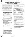
Loading a WAV file into a track
(Importing a WAV file)...................... 172
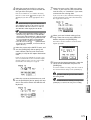
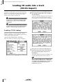
Loading CD audio into a track
(CD-DA Import) ................................ 174
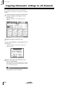
Copying attenuator settings to all channels
.................... 224
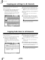
Copying delay time/phase settings to all
channels............................................. 225
Copying pan settings to all channels... 226
Copying fade times to all channels ..... 226
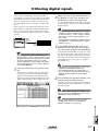
Dithering digital signals ...................... 227
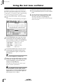
Using the test tone oscillator .............. 228
Using the metronome ......................... 229
Mixing and recording multiple channels 230
Pingpong-recording multiple tracks to one
or two tracks...................................... 232
About mastering ................................. 179
Stereo tracks that can be mastered..... 179
Media that can be used with the CD-RW
drive .................................................. 179
Track At Once and Disc At Once ....... 180
Checking the free space on the internal
hard disk ............................................ 181
Welcome to the world of the AW2816
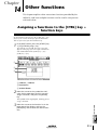
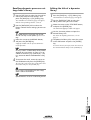
Chapter14 Other functions..... 215
Assigning a functions to the [CTRL] key +
function keys ..................................... 215
Making fine adjustments to the pitch of an
entire song (Vari-pitch)...................... 217
Saving channel settings (Channel Library)
.................... 218
Cautions when writing to a WAV file .......167
Checking the free space on the internal hard
disk .........................................................167
Exporting tracks to WAV files ...................168
Exporting virtual tracks to WAV files ........171
Chapter12 Mastering...............179
1
About the MIDI Remote function..............206
Using the default MIDI Remote settings....207
Assigning MIDI messages to faders ...........208
Assigning MIDI messages to the [ON] keys 210
Storing EQ settings in a library..................220
Recalling EQ settings from a library..........221
Editing the title of an EQ library................221
Playing an audio CD (CD Play)........... 177
Parts and their functions
Using the TO HOST connector to connect
the AW2816 and your computer....... 190
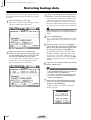
Restoring backup data ........................ 164
Tidying up the data of the internal hard disk
(Defrag) ............................................. 166
Writing a track to a WAV file
(Exporting a WAV file) ...................... 167
Enabling CD-DA loading ..........................174
Loading CD-DA data and assigning it to a track
.......................175
Before you begin
Storing dynamics processor settings
(Dynamics Library) ............................ 222
Managing songs
10
Using the internal hard disk/
external storage devices
11
Mastering
12
MIDI
13
Other functions
14
Table of contents
vii
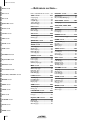
Table of contents
SONG screen
—Reference section—
FILE screen
How to read the Reference section .... 236
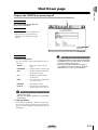
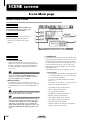
SONG screen ........................237
CD screen
QUICK REC screen
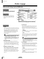
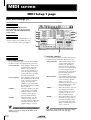
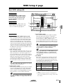
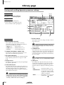
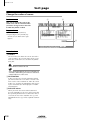
Song List page ..................................... 237
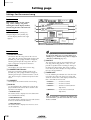
Setting page......................................... 238
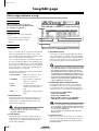
Song Edit page..................................... 240
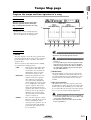
Tempo Map page ................................ 241
Shut Down page.................................. 243
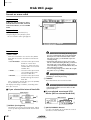
FILE screen...........................244
SETUP screen
Backup page........................................ 244
Restore page........................................ 246
Disk Util. page .................................... 248
UTILITY screen
CD screen ............................250
CD Write page .................................... 250
CD Play page ...................................... 252
MIDI screen
PATCH screen
VIEW screen
PAN/ROUTE screen
EQ/ATT/GRP screen
DYN/DLY screen
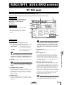
AUX1–AUX4 screens
EDIT screen
SETUP screen .......................256
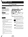
D.in Setup page................................... 256
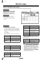
Monitor page ...................................... 258
Dither Out page.................................. 259
Dither TRK page.................................. 260
Solo Setup page................................... 261
UTILITY screen.....................263
Oscillator page.................................... 263
Prefer.1 page....................................... 264
Prefer. 2 page...................................... 266
Prefer. 3 page...................................... 268
CTRL Key Asgn. page .......................... 270
MIDI screen .........................272
MIDI Setup 1 page .............................. 272
MIDI Setup 2 page .............................. 275
PGM Asgn. page.................................. 276
CTL Asgn. page ................................... 277
Bulk Dump page ................................. 281
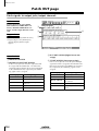
Patch IN page ..................................... 283
Patch OUT page.................................. 284
Patch Lib page..................................... 286
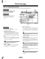
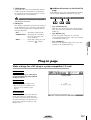
Plug-in page ........................................ 287
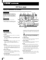
VIEW screen ........................288
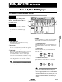
PAN/ROUTE screen..............293
Pan 1–8/Pan MONI page .................... 293
Pair page ............................................. 295
EQ/Att page ........................................ 296
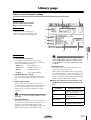
Library page ........................................ 298
Fader Grp page ................................... 300
Mute Grp page.................................... 301
SCENE screen
METER screen
viii
Eff. Edit page ....................................... 309
Library page ........................................ 311
Pre/Pst page ........................................ 313
REMOTE screen.................... 314
Remote A–Remote D pages ................ 314
Quick Rec page................................... 254
EQ/ATT/GRP screen ............296
AUTOMIX screen
AUX5/EFF1, AUX6/EFF2
screens ................................ 309
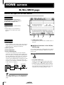
HOME screen ....................... 318
CH View page ..................................... 288
Library page ........................................ 291
TRACK screen
AUX1–AUX4 screens............ 307
Pre/Pst page ........................................ 307
IN/Rtn/MONI page............................. 318
Bus page.............................................. 319
Omni/ST page..................................... 320
Option page ........................................ 321
PATCH screen ......................283
HOME screen
Dyn. Edit page..................................... 302
Library page ........................................ 304
Dly/ø1–8/Dly/øMONI page ............... 306
QUICK REC screen................254
AUX5/EFF1, AUX6/EFF2 screens
REMOTE screen
DYN/DLY screen.................. 302
Table of contents
TRACK screen ...................... 322
TR View page ...................................... 322
V. Track page ...................................... 324
Stereo page ......................................... 325
Mark Adj. page.................................... 327
EDIT screen.......................... 329
TR Edit page ........................................ 329
V.TR Edit page..................................... 331
CD Import page .................................. 333
WavImport page ................................. 335
TR Import page ................................... 337
AUTOMIX screen ................. 338
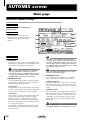
Main page ........................................... 338
Memory page...................................... 341
Fader Edit page ................................... 343
Event List page .................................... 344
SCENE screen ....................... 346
Scene Mem page................................. 346
Fade Time page................................... 348
RCL. Safe page .................................... 349
Sort page............................................. 350
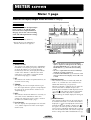
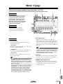
METER screen ...................... 351
Meter 1 page....................................... 351
Meter 2 page....................................... 353
Appendix
—Appendix—
Preset EQ Program Parameters........... 356
Preset Effects Programs....................... 360
Effects Parameters............................... 362
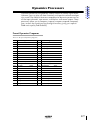
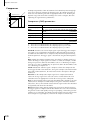
Dynamics Processors .......................... 377
Preset Dynamics Programs .......................377
Index
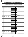
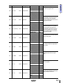
Preset Dynamics Program Parameters 382
Troubleshooting.................................. 388
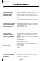
Display message list ............................ 392
Messages ..................................................392
Popup messages .......................................394
Messages at power-on ..............................395
Specifications...................................... 396
General Specifications..............................396
Mixer section............................................397
Recorder section.......................................399
Controls ....................................................400
Control I/O ...............................................400
Dimensions ......................................... 401
MIDI data format................................ 402
MIDI Implementation Chart ............. 414
Index....................................415
Block diagram
Table of contents
ix
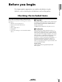
Before you begin
Before you begin
This chapter explains preparations you need to make before using the
AW2816, such as checking the included items and installing options.
Checking the included items
Please make sure that the package contains the following items. If any items are missing, please contact
your dealer.
■ Copyright
• Owner’s manual (this document): 1
No part of the AW2816 software or the manuals may
be reproduced or distributed in any form or by any
means without the prior written authorization of
Yamaha Corporation.
• Tutorial: 1
© 2000 Yamaha Corporation. All rights reserved.
• AW2816 mixer/recorder unit: 1
• Power supply cable: 1
■ Trademarks
• CD-ROM: 1
• Screws for installing 2.5 inch hard disk/CD-RW
drive: 8
ADAT MultiChannel Optical Digital Interface is a
trademark and ADAT and Alesis are registered trademarks of Alesis Corporation. Apple and Macintosh are
registered trademarks of Apple Computer, Inc. Tascam
Digital Interface is a trademark and Tascam and Teac
are registered trademarks of Teac Corporation.
MS-DOS is a registered trademark and Windows is a
trademark of Microsoft Corporation. Yamaha is a
trademark of Yamaha Corporation. All other trademarks are the property of their respective holders and
are hereby acknowledged.
Yamaha website
<http://www.yamaha.co.jp/product/proaudio/
homeenglish/>
Operation section
1
Before you begin
Installing an internal hard disk
You must install a hard disk in the AW2816 before using it. If you attempt to use the
AW2816 without installing a hard disk, the recorder section and mixer section will
fail to operate correctly, and the AW2816 will be damaged as well.
About the internal hard disk
On the AW2816, all data necessary for reproducing a
composition (mixer settings, recorder settings, audio
data etc.) is stored on the hard disk as a “song.”
The following steps describe the procedure by which
the 2.5 inch IDE hard disk is attached to the hard disk
cover plate located on the bottom of the AW2816 for
installation.
An internal hard disk is installed by attaching it to the
inside of the hard disk cover plate located on the bottom panel of the AW2816. Hard disks with the following specifications can be used.
• Hard disks are precision devices. Do not subject
them to physical shock or static electricity, etc.
• Do not place a hard disk nearby devices that produce a strong magnetic field, or in locations of
extreme cold, heat, or moisture.
• Before you handle a hard disk, touch your hand to a
grounded metallic object to release any static
charge that may be present in your body or clothing.
If you fail to do so, static electricity may damage the
hard disk.
• Never attempt to disassemble a hard disk or apply
excessive force to it.
• In order to install the internal hard disk, you will
need to turn the AW2816 upside down. Please make
sure that your work surface is spacious enough.
• The AW2816 is shipped with four screws for attaching a 2.5 inch hard disk, and four screws for attaching a CD-RW drive, making a total of eight included
screws of the same type.
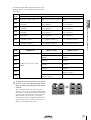
• Type: IDE 2.5 inch (attachment location conforms to SFF-8201)
• Thickness: no particular limitation
• Capacity: no particular limitation (however, the
AW2816 can use a maximum capacity of 64 GB)
• Models known to work: consult your local
Yamaha distributor or refer to the website at the
following URL.
<http://www.aw2816.com/>
• By “models known to work,” we mean commercially
available models that Yamaha has obtained, installed
in the AW2816, and successfully tested by means of
various operational tests. However, we cannot take
into account slight differences in performance that
may occur due to the manufacturing tolerances of
each manufacturer.
• Hard disks are precision devices. Strong physical
shock, magnetism, static electricity, or excessive current etc. can damage the data on a hard disk. You
must use media such as an external SCSI device or
CD-RW to backup your important musical data.
• Please be aware that Yamaha Corporation will
accept no responsibility for any damages, neither
direct nor indirect, resulting from the use of any of
the above hard disks.
1
You will need the following items.
• The AW2816 itself
• A 2.5 inch IDE hard disk (sold separately) for
installation
• Four screws included with the AW2816 for
attaching the 2.5 inch hard disk
• A philips (+) screwdriver
• Work surface
2
Make sure that the power of the AW2816
is turned off. For safety’s sake, disconnect
the power cable from the AC outlet.
Installation
Please read and observe the cautions on installing
optional equipment listed at the beginning of this
manual.
2
Operation section
Always switch off the power for the main unit and all
peripherals, unplug the power cord for the main unit
from the outlet, then disconnect the cables connecting the main unit with the peripherals before starting
installation work.
Spread a soft cloth over your work surface,
and place magazines or books to support
the four corners of the AW2816 so that the
faders, keys, and other controllers on the
top panel will not be damaged. Then turn
the AW2816 face down.
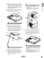
4
From the bottom, unfasten the hard disk
cover plate to which the internal 2.5 inch
IDE hard disk will be attached.
• Even if the connector is difficult to insert, do not
attempt to insert it by applying excessive force.
Doing so may damage the hard disk, or you may
injure yourself.
• When inserting the connector, be careful that it is
not mis-aligned up/down or left/right.
Before you begin
3
Hard disk
cover plate
The screws you remove will be used again to fasten
the cover plate, so be careful not to lose them.
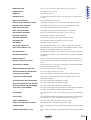
5
Turn over the hard disk cover plate. As
shown in the illustration, place the hard
disk to be installed on the cover plate,
align the screw holes of the hard disk with
the holes of the cover panel, and use a
screwdriver and the included screws to fasten the hard disk at four locations.
7
As shown in the illustration place the cover
plate with the attached hard disk back
onto the bottom panel of the AW2816,
and fasten the cover plate to the bottom
panel using the four screws that you
removed in step 4.
Connector
If you fail to tighten the screws all the way, the hard
disk may vibrate and fail to operate correctly.
6
Pull out the flat cable from inside the
AW2816, and plug the flat cable into the
connector of the hard disk as shown in the
illustration. Press both ends of the flat
cable connector to ensure that it is firmly
plugged in all the way.
• You must use the same screws that you removed in
step 4, or identical screws. Using longer screws may
damage the interior of the unit, or may cause electrical shock.
• Do not turn on the power of the AW2816 until all
options have been installed.
• When you turn on the power of the AW2816 after
installing a new hard disk, formatting of the hard
disk will begin automatically (→ P.11).
Operation section
3
Before you begin
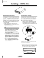
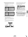
Installing a CD-RW drive
About the CD-RW drives
CD-RW drive settings
A CD-RW drive is an option that allows you to create
music CD’s, to backup/restore internal hard disk data,
to play a music CD or to read a CD-ROM. An internal-type CD-RW drive can be installed by removing
the CD-RW drive cover from the front panel. CD-RW
drives with the following specifications can be used.
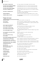
Insert the jumper (included with the CD-RW drive)
into the jumper switch on the rear panel of the CDRW drive to set your CD-RW drive to function as a
SLAVE unit. The AW2816 will not start up if the CDRW is set to a mode other than SLAVE.
• Interface: ATAPI
• Models known to work: consult your local
Yamaha distributor or refer to the website at the
following URL.
<http://www.aw2816.com/>
• If you are installing a CD-RW drive manufactured by Yamaha, it will be set to SLAVE when
shipped from the factory, so you do not need to
change the setting.
CSEL
SLAVE
MASTER
• CD-RW drives designed for internal installation can
be installed in the AW2816. Please be aware that
internal CD-RW drives designed for use with the
AW4416 cannot be used in the AW2816.
In the case of external SCSI-connected CD-RW
drives, a CD-RW drive usable with the AW4416 can
also be used with the AW2816.
• By “models known to work,” we mean commercially
available models that Yamaha has obtained, installed
in the AW2816, and successfully tested by means of
various operational tests. However, we cannot take
into account slight differences in performance that
may occur due to the manufacturing tolerances of
each manufacturer.
• Please be aware that Yamaha Corporation will
accept no responsibility for any damages, neither
direct nor indirect, resulting from the use of any of
the above CD-RW drives.
Set to SLAVE
Jumper switch
Jumper
For details on this setting, refer to the manual that
came with your CD-RW drive.
* Note that the cover panel of the AW2816 cannot be
attached to a CD-RW drive with a lid-type tray. The
AW2816’s cover panel can be attached to a CD-RW
drive with a tray of the following dimensions.
Maximum 138 mm
4
Operation section
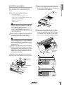
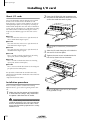
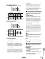
Installation procedure
Turn the CD-RW drive over, and insert it little by little, stopping when the connector
end of the CD-RW drive enters the opening
in the bottom of the AW2816.
6
Connect the flat cable (1) and CD-RW
drive power supply connector (2) (from
inside the AW2816) to the connectors of
the CD-RW drive. Connect the flat cable
first, and then the power supply connector.
Please carefully read the cautions for installing
optional equipment given at the beginning of this
manual.
1
Before you begin
5
You will need the following items.
• The AW2816 itself
• Internal CD-RW drive (option)
• Four screws (included with the AW2816) for
attaching the CD-RW drive
• Philips (+) screwdriver
• Work surface
• In order to install the CD-RW drive you will need to
turn the AW2816 on its back. Make sure that you
have a sufficiently broad work surface.
• The AW2816 is shipped with four screws for attaching the 2.5 inch hard disk, and four screws for
attaching the CD-RW drive, making a total of eight
screws of the same type.
2
Make sure that the power of the AW2816
is turned off. For safety’s sake, disconnect
the power cable from the AC outlet.
Always switch off the power for the main unit and all
peripherals, unplug the power cord for the main unit
from the outlet, then disconnect the cables connecting the main unit with the peripherals before starting
installation work.
3
4
Spread a soft cloth over your work surface,
and place magazines or books to support
the four corners of the AW2816 so that the
faders, keys, and other controllers on the
top panel will not be damaged. Then turn
the AW2816 face down.
Power supply
connector
Flat cable
Remove the CD-RW drive cover from the
front panel, and remove the bottom panel.
Bottom panel
CD-R/RW drive
cover panel
Operation section
5
Before you begin
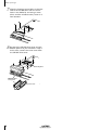
7
Align the fastening screw-holes on the bottom of the CD-RW drive with the screwholes in the AW2816, and using a screwdriver and the included screws, fasten it in
four locations.
8
Re-attach the CD-RW drive cover and the
bottom panel that you removed in step 4.
At this time, remove the inner cover from
the CD-RW drive cover.
Bottom panel
CD-R/RW drive
cover panel
Inner cover
6
Operation section
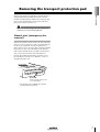
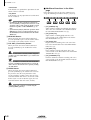
Removing the transport protection pad
Before you begin
The disc tray of some CD-RW drive models contains a
transport protection pad that protects the internal
mechanism from physical shock suffered during shipment. If your CD-RW drive contains this protective
pad, please remove it before use.
Be sure to save the transport protection pad for the
next time you need to transport the unit.
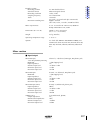
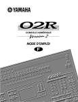
Manual eject (emergency disc
removal)
Manual eject allows you to remove the disc manually
in the case of an emergency such as a malfunction of
the disc tray mechanism (usually temporary) or a
power failure. Please be aware that using this method
frequently can cause the CD-RW drive to malfunction. For the location of the eject hole and the procedure, refer to the manual of your CD-RW drive.
In order to perform this operation, you will need a
pin-like object 2 mm or less in diameter, such as a
straightened paper clip.
Eject Hall
Insert a pin-like object 2 mm
or less in diameter.
* This diagram shows a CD-RW drive manufactured by Yamaha Corporation.
Operation section
7
Before you begin
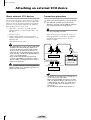
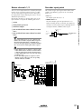
Attaching an external SCSI device
About external SCSI devices
Connection procedure
The external SCSI devices referred to here are storage
devices used to backup/restore the internal data of the
AW2816, and can be connected to the SCSI connector on the rear panel of the AW2816. The following
types of storage device can be used.
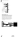
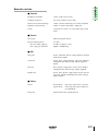
1
Make sure that the power is turned off for
the AW2816 and for the external SCSI
device(s), and use a SCSI cable to connect
the SCSI connectors of each device.
• Type of drive: MO drives (128 MB, 230 MB,
540MB, 640 MB 1.3 GB), hard disk drives, CDRW drives
Use only good-quality SCSI cables.
• Interface: SCSI-2
When connecting an external SCSI device, use
only high impedance SCSI cables of 100 ohms
(±10 ohms) impedance that are 1 meter or
shorter in length.
• Models known to work: consult your local
Yamaha distributor or refer to the website at the
following URL.
<http://www.aw2816.com/>
• By “models known to work,” we mean commercially
available models that Yamaha has obtained, connected to the AW2816, and successfully tested by
means of various operational tests. However, we
cannot take into account slight differences in performance that may occur due to the manufacturing tolerances of each manufacturer.
• Please be aware that Yamaha Corporation will
accept no responsibility for any damages, neither
direct nor indirect, resulting from the use of any of
the above storage devices.
It is not possible to directly record or play back audio
signals in realtime on an external storage device connected to the SCSI connector.
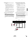
SCSI
connector
SCSI
connector
SCSI
connector
External SCSI device 1
AW2816
ID=6 (fixed)
Terminator
SCSI
connector
SCSI
connector
External SCSI device 2
Note
• A maximum of seven SCSI devices (SCSI ID= 0–5,7)
can be connected in a daisy-chain.
• When connecting multiple SCSI devices, you must
make sure that the SCSI ID of each device does not
conflict with any other device. (For details on how
to set the SCSI ID, refer to the manuals for your
SCSI devices.)
• The SCSI ID of the AW2816 itself is fixed at “6.”
8
Operation section
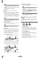
2
Attach a terminator to the last SCSI device
in the chain.
Before using an external SCSI device, you will need to
format it. For details on this procedure, refer to
page 160.
■ About terminators
Before you begin
A “terminator” is a device that terminates the
SCSI signal at the end of the chain, and is normally attached to the vacant SCSI connector of
the last device in the daisy chain. If the SCSI
device itself has a built-in terminator, turn it on.
(For details on how to turn on the internal terminator, refer to the manual of your SCSI device.)
● External SCSI devices with 25-pin connectors
Most SCSI cables with 25-pin connectors at both
ends do not meet SCSI specifications. For this reason if the system includes a SCSI device that uses a
25-pin connector, the problems may be due to this
type of cable.
● Daisy-chain connection
Sometimes the operation of a SCSI bus will be
unstable because of daisy-chain connections. Connect only the SCSI device you are using to the
AW2816.
● Power supply of SCSI devices
When using the system, turn on the power of all
connected SCSI devices. Operation of the SCSI bus
cannot be guaranteed if one of the connected
devices is not turned on.
“Termination” refers to the process of applying a resistor appropriate for the impedance of the SCSI bus to
terminate the end of the circuit. The resistor required
for this is called the “terminator.” Normally, a terminator must be installed at the beginning and end of the
SCSI bus (in the case of the example in the previous
page, this would be the AW2816 itself, and the SCSI
device connected to the end of the daisy chain).
However, this is only a general principle, and is not
an absolute. Depending on the combination of SCSI
devices, the order of connection, or on the length of
the SCSI cables, there may be cases in which better
results are obtained by terminating only one end of
the chain. If problems occur such as the AW2816 failing to start up when an external SCSI device is connected, try defeating the terminator of the external
SCSI device. (The terminator inside the AW2816 is
always on, and cannot be defeated.)
■ About SCSI errors
The SCSI bus is able to transfer data in a stable manner only if all connected SCSI devices are operating
correctly. If the SCSI bus of the AW2816 is connected
to a device whose operation is unstable or which produces noise, errors may occur in other devices, or the
AW2816 may fail to start up correctly. If such problems occur, check the following points.
● Check the SCSI ID
Make sure that the SCSI ID of each SCSI device
(including the AW2816) does not conflict with the
SCSI ID of any other device. The SCSI ID of the
AW2816 is fixed at “6.”
● Check the terminator
Check the location of the terminator. Under certain
conditions, better results may be obtained by terminating only one end of the SCSI chain.
● Check the SCSI cables
Since errors are often caused by low-quality SCSI
cables or unnecessarily long SCSI cables, you
should avoid using such cables. Please use doubleshielded cables that are as short as possible. It is
also important that the shield within the cable is
grounded to the connector.
Operation section
9
Before you begin
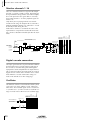
Installing I/O card
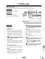
2
About I/O cards
I/O cards compatible with the Yamaha mini-YGDAI
format can be installed in the OPTION I/O slot
located on the rear panel of the AW2816 in order to
add input/output ports. For example by installing an
ADAT format compatible I/O card into an OPTION I/
O slot, you can transmit/receive eight channels of digital audio to/from an ADAT format digital recorder.
From the OPTION I/O slot located on the
rear panel of the AW2816, remove the two
screws that hold the cover in place.
At present, the following types of I/O cards can be
used.
● MY8-AT
This card transmits and receives eight channels of
Alesis ADAT format digital signals.
● MY8-TD
This card transmits and receives eight channels of
TASCAM format digital signals.
● MY8-AE
This card transmits and receives eight channels of
AES/EBU format digital signals.
● MY8-AD
This is an A/D card with eight channels of analog
input jacks (balanced TRS phone jacks).
Please keep the cover and screws you removed in a
safe place.
3
4
Slide the I/O card along the rails inside the
slot until it clicks into place.
Tighten the two screws included with the
I/O card to fasten the card securely.
● MY4-AD
This is an A/D card with four channels of analog
input jacks (balanced XLR jacks).
● MY4-DA
This is a D/A card with four channels of analog output jacks (balanced XLR jacks).
For up-to-date information on available MY cards,
contact your local Yamaha distributor or check the following website.
<http://www.aw2816.com/>
Installation procedure
Please carefully read the cautions for installing
optional devices, given at the beginning of this manual.
1
Make sure that the power of the AW2816
is turned off. For safety’s sake, disconnect
the power cable from the AC outlet.
Always switch off the power for the main unit and all
peripherals, unplug the power cord for the main unit
from the outlet, then disconnect the cables connecting the main unit with the peripherals before starting
installation work.
10
Operation section
Please note that if the screws are loose, the card may
not be grounded correctly.
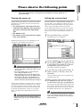
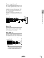
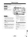
Please observe the following points
Before you begin
This section explains how to turn the power of the AW2816 on and off, and how to set
the internal clock.
Turning the power on
Setting the internal clock
When turning on the power of a system that includes
the AW2816, each device must be turned on in the
following order.
When the AW2816 is shipped from the factory, the
internal clock is set to Japan time. When you save a
song you created on the AW2816, the date and time
will be stored according to this internal clock.
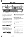
1 Any storage devices connected to the SCSI
connector of the AW2816, and external tone
generators connected to the input/output
jacks
B The AW2816 itself
C The monitor system connected to the output
jacks or the AW2816
Use the following procedure to set the date and time
of the internal clock after replacing the internal battery, or if you need to set the clock for any other reason.
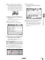
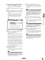
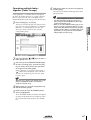
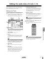
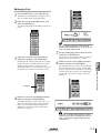
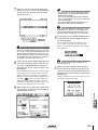
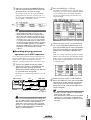
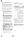
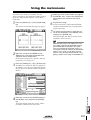
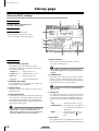
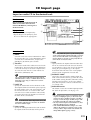
1
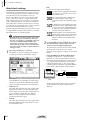
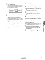
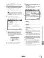
Press the [UTILITY] key → [F4] key.
2
Use the CURSOR [ ] key to move the cursor (the blinking area in the display) to the
Y (year) field in the CLOCK area, and turn
the [DATA/JOG] dial to set the year.
The following screen will appear.
Following the opening screen, the following screen
will appear in the display of the AW2816.
• If the AW2816 is powered-on when a SCSI-connected external device is turned off, it may not start
up correctly.
• Do not turn off the power of a SCSI-connected
device while the AW2816 is in use.
• Before turning the power on, check that the power
cable plug is firmly connected to the AW2816 and to
the AC outlet. If the power is accidentally disconnected (turned off) while the AW2816 is in use, the
AW2816 itself and/or the hard disk may be damaged.
The first time the power is turned on after a new internal hard disk is installed in the AW2816, the display
will indicate “Format OK? [Y (Enter)/N (Any)].” If you
press the [ENTER] key at this time, the hard disk will
be formatted automatically, and the screen shown
above will appear when formatting has been completed.
The clock field will begin blinking.
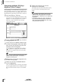
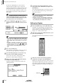
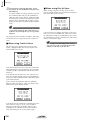
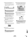
3
In the same way, input the M (month), D
(date), h (hour), m (minute), and s (second) fields.
The W (weekday) field will be set automatically
according to the date.
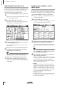
4
When you have input all of the values, use
the CURSOR keys to move the cursor to
the SET button, and press the [ENTER] key.
The CLOCK area will stop blinking, and the new
date and time will take effect. If you decide not
to change the date and time, move the cursor to
the RESET button and press the [ENTER] key.
Tip!
Never turn off the power of the AW2816 while formatting is in progress. Doing so may damage the hard
disk itself.
Operation section
The internal clock continues to operate even when the
power of the AW2816 is turned off. Once you have
set the clock, you will not need to reset it unless you
change the battery.
11
Before you begin
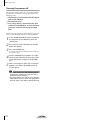
Turning the power off
When turning off the power of a system that includes
the AW2816, each device must be turned off in the
following order.
1 The monitor system connected to the output
jacks or the AW2816
B The AW2816 itself
C Any storage devices connected to the SCSI
connector of the AW2816, and external tone
generators connected to the input/output
jacks
When turning off the power of the AW2816 itself, you
must use the shutdown procedure described below.
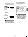
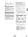
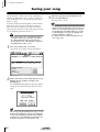
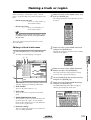
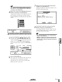
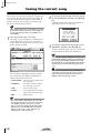
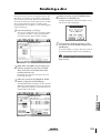
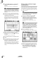
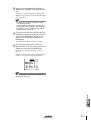
1
In the WORK NAVIGATE section located on
the top panel of the AW2816, press the
[SONG] key.
2
3
Press the [F5] (SHUT DOWN) key located
below the display.
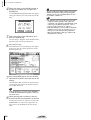
4
Use the CURSOR keys located in the right
center of the top panel to move the cursor
to the OK button, and press the [ENTER]
key.
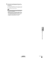
5
When a message of “Now safe to turn off”
appears, turn off the [POWER] switch of
the rear panel.
Press the [ENTER] key.
A message will ask you whether you want to save
the current song.
• If you turn off the power of the AW2816 without
using the above shutdown procedure, the data on
the hard disk may be damaged.
• Never turn off the power while the access indicator
which indicates the access status of the internal hard
disk is lit. Doing so may damage the hard disk itself.
12
Operation section
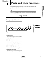
Chapter
1
Parts and their functions
This chapter explains the functions of each part of the AW2816’s top
panel, rear panel, and front panel.
1
Parts and their functions
The names of controllers (keys and knobs etc.) on the top panel are enclosed in square brackets
[ ] in order to distinguish them from the software knobs and buttons that appear in the display.
Example: [SEL] key, [GAIN] control
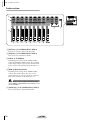
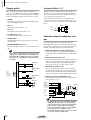
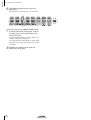
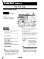
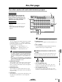
Top panel
Analog input/output section
2
3
4
1
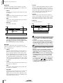
A [GAIN] control
These knobs adjust the input sensitivity of INPUT
jacks 1–8 over a range of +4 dB to –46 dB. They
support signals ranging from line level devices
such as synthesizers to mic inputs.
B [PEAK] indicators
A [PEAK] indicator will light red if the input signal
that has passed through the [GAIN] control
reaches a level 3 dB below the clipping point. In
order to record at the optimal level, adjust the
[GAIN] control (1) so that this indicator flickers
briefly when you play most loudly.
C [PHONES] (headphones) control
This knob adjusts the volume of the headphones
connected to the rear panel PHONES jack.
D [MONITOR OUT] control
This knob adjusts the level of the signal that is output from the rear panel MONITOR OUT jacks.
Operation section
13
Chapter
Parts and their functions
1
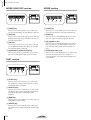
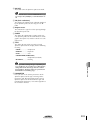
WORK NAVIGATE section
MIXER section
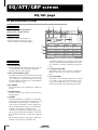
EQ/ATT/GRP
EQ/ATT/GRP
1
2
3
4
1
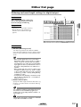
A [SONG] key
B [FILE] key
C [CD] key
This key accesses the CD screen, where you can
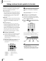
use an optional CD-RW drive to create an audio
CD, or play back an audio CD.
D [QUICK REC] (Quick Record) key
This key accesses the VIEW screen, where you can
view all mix parameters for a specified channel.
UNIT section
3
This key accesses the PAN/ROUTE screen, where
you can set pan and routing for each channel.
C EQ (Equalizer) key
This key accesses the EQ/ATT/GRP screen, where
you can set the EQ and attenuator of each channel, and make fader group and mute group settings.
D [DYN] (Dynamics) key
This key accesses the QUICK REC screen, where
you can instantly patch input signals to tracks.
This key accesses the DYN/DLY screen, where you
can make dynamics processor settings for a
selected channel, and set the delay and phase of
each channel.
4
A [SETUP] key
This key accesses the SETUP screen, where you
can make basic settings for the AW2816 such as
word clock, dither, and solo.
B [UTILITY] key
This key accesses the UTILITY screen, where you
can operate the test tone oscillator, and make settings for the operating environment of the
AW2816.
C [MID] key
This key accesses the MIDI screen, where you can
make MIDI-related settings.
D [PATCH] key
This key accesses the PATCH screen, where you
can patch external inputs/outputs to internal signal
routes.
14
4
B [PAN] key
This key accesses the FILE screen, where you can
backup and restore songs, and format or erase an
internal/external drive.
2
3
A [VIEW] key
This key accesses the SONG screen, where you
can save or load songs, or shut down the AW2816.
1
2
DYN/DLY/
DYN/DLY/
Operation section
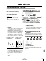
FADER MODE section
MIXING LAYER section
1
1
2
3
4
2
Parts and their functions
1
3
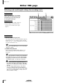
A INPUT [1-8] key
B RECORDER [1-8] key
This section selects the parameters that will be controlled by the top panel faders 1–8. The selected key
will light.
A [HOME] key
When this key is on, you can use faders 1–8 to
control the input levels of the channels currently
selected in the MIXING LAYER section. The display will show the HOME screen, where you can
view meters that indicate the input/output levels of
each channel.
B [AUX 5]/[AUX 6] keys
When these keys are on, you can use faders 1–8 to
adjust the send levels of the signals sent to internal
effects 1/2 from the channels currently selected in
the MIXING LAYER section. The display will show
the AUX5/EFF1 screen or AUX6/EFF2 screen,
where you can make on/off and pre/post settings
for the signals sent from each channel to internal
effects 1/2, and set effect parameters.
C RECORDER [9-16] key
These keys select the channels (mixing layer) that
will be operated by [SEL] keys 1–8, [ON] keys 1–
8, and faders 1–8.
The currently selected key will light. When the
respective key is selected, the [SEL] keys 1–8,
[ON] keys 1–8, and faders 1–8 will operate the
mixing layers listed below.
● When the INPUT [1-8] key is lit
Input channels 1–8
● When the RECORDER [1-8] key is lit
Monitor channels 1–8
● When the RECORDER [9-16] key is lit
Monitor channels 9–16
For details on channels and mixing layers, refer to
page 38.
C [AUX 1]–[AUX 4] keys
When this key is on, you can use faders 1–8 to
control the send levels of the signals sent to AUX
buses 1–4 from the channels selected in the MIXING LAYER section. The display will show the
AUX 1–AUX 4 screens, where you can make on/
off and pre/post settings for the signals sent from
each channel to AUX 1–4.
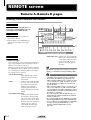
D [REMOTE] key
When this key is on, you can use faders 1–8 and
[ON] keys 1–8 to remotely control external MIDI
devices. The display will show the REMOTE
screen, where you can make settings related to
remote control.
Operation section
15
Chapter
Parts and their functions
1
Fader section
1
2
4
3
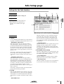
A [SEL] keys (1–8/STEREO/RTN 1/RTN 2)
These keys select the channel for operation.
B [ON] keys (1–8/STEREO/RTN 1/RTN 2)
These keys turn each channel on/off.
C Faders (1–8/STEREO)
According to the settings of the FADER MODE
section and MIXING LAYER section, these moving
faders adjust either the input level of each channel
or the send level of each channel to AUX buses 1–
6.
D [RTN 1]/[RTN 2] controls
According to the settings of the FADER MODE
section, these knobs adjust either the level of
return channels 1/2 (effect return) or the send level
from return channels 1/2 to AUX buses 1–6.
Return channel 1 does not have a send level to AUX
bus 5. Similarly, return channel 2 does not have a send
level to AUX bus 6.
E [SOLO] key (1–16/STEREO/RTN 1/RTN 2)
This key switches the Solo function on/off.
16
Operation section
5
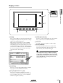
Display section
1
Parts and their functions
6
1
5
2
3
4
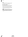
A Display
D [CTRL] (Control) key
This is a 320 x 240 pixel liquid crystal display with
backlight, that displays the mix parameter settings
and the current operating status.
When you press one of the keys in the WORK
NAVIGATE or UNIT section, the screen for the
corresponding key will appear. Most screens consist of multiple “pages” (the name of the pages in
each screen are indicated by tabs at the bottom of
the screen), and you can use the [F1]–[F5] keys
(3) to access the desired page.
This key is used in conjunction with the function
keys (3) to execute user-defined functions.
E Contrast
This knob adjusts the brightness of the display.
F Access indicator
This indicator indicates the access status of the
internal hard disk. When the hard disk is being
read or written, this indicator will light.
Screen
pages
Never turn off the power of the AW2816 when the
access indicator is lit. Doing so will not only damage
the data on the internal hard disk, but may also damage the hard disk itself. When you want to turn off the
power of the AW2816, you must perform the shutdown procedure (→P.12).
B [SHIFT] key
This key is used in conjunction with the function
keys (3) to execute additional functions.
C [F1]–[F5] (Function 1–5) keys
These keys select pages within the currently
selected screen. When the [SHIFT] key or [CTRL]
key is held down, these keys execute additional
functions assigned to each key.
Operation section
17
Chapter
Parts and their functions
1
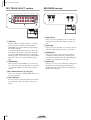
REC TRACK SELECT section
RECORDER section
1
2
1
3
2
3
4
4
A [TRACK] key
A [CUE] key
This key allows the output of tracks 1–16 or the
stereo track to be monitored directly from the
MONITOR OUT jacks without passing through
the monitor channel.
Use the REC TRACK SELECT keys (3) to select a
track. When you press the [CUE] key, the [CUE]
key and the REC TRACK SELECT keys will blink,
allowing you to select a track. Press a REC TRACK
SELECT key to select a track, and that key will
light.
B [METER] key
This key accesses the TRACK screen, where you
can operate the audio tracks of the recorder section.
B [EDIT] key
This key accesses the EDIT screen, where you can
edit the audio tracks that have been recorded.
C [UNDO] key
This key cancels the most recently performed
recording or editing operation, returning to the
previous state (Undo). When the Undo function is
available, the [UNDO] key will light.
D [REDO] key
This key accesses the METER screen, where you
can view meters of the input/output level of tracks
1–16 and the output level of the stereo output
channel.
This key re-executes the recording or editing operation that was cancelled by the [UNDO] key
(Redo). When the Redo function is available, the
[REDO] key will light.
C REC TRACK SELECT [1]–[16]/[ST]
These keys select the recording track (tracks 1–16
or the stereo track).
D [ALL SAFE] key
This key cancels record-ready mode for all tracks.
If any tracks are muted, all muting will be cancelled.
18
Operation section
AUTOMATION section
CURSOR/JOG&SHUTTLE section
1
2
Parts and their functions
1
1
A [AUTOMIX] key
3
2
This key accesses the AUTOMIX screen, where
you can perform automix operations. By using
automix, operations of mix parameters such as the
faders and [ON] keys can be recorded in realtime.
B [SCENE] key
This key accesses the SCENE screen, where you
can perform scene memory operations. By using
scene memories, you can save the current state of
the mixer section and the input/output patching
state.
SCENE MEMORY section
4
5
1
2
A [JOG ON] key
3
A [STORE] key
This key saves the current state of the mixer section and input/output patching to the scene number shown in the display.
B[
]/[
] keys
These keys select the store destination or recall
source scene number.
C [RECALL] key
This key is an on/off switch for the Nudge function
(a destination that repeatedly plays a specified
region before or after the current location) controlled by the [DATA/JOG], [SHUTTLE] dial. When
the Nudge function is on, the [JOG ON] key will
light.
B [DATA/JOG] dial
Depending on the on/off status of the [JOG ON]
key and the [NUM LOCATE] key of the Locate section, this dial is used to edit parameter values or to
operate the Nudge function.
C [SHUTTLE] dial
This key recalls the scene number currently shown
in the display.
Depending on the on/off status of the [JOG ON]
key, this dial rewinds or fast-forwards the playback
(review or cue), or operates the Nudge function.
D CURSOR [
]/[
]/[ ]/[ ] keys
These keys are used to move the cursor (the blinking box) in the display.
E [ENTER] key
This key is used to operate a button displayed in
the screen, to finalize a numerical value that you
input, or to execute a specific function.
Operation section
19
Chapter
Parts and their functions
1
G [REPEAT] key
LOCATE section
This key is an on/off switch for the A-B Repeat
function which repeatedly plays a specified
region.
H [A]/[B] keys
These keys set the beginning (A point) and end (B
point) of the region played by the A-B Repeat function. These keys can also be used as locate keys to
specify the A point or B point as locate destinations.
1
2
3
I [ROLL BACK] key
This key rewinds the current location by a specified distance.
4
7
8
5
6
J[
9
K [RTZ] (Return to zero) key
] key
This key locates to the absolute time zero location
(start point).
This key locates to the counter zero location
(when the counter is displaying measures, this will
be the beginning of the first measure).
J
K
L
M
L[
] key
This key locates to the last location at which audio
is recorded (end point).
M [CANCEL] key
A [NUM LOCATE] key
This key is used to specify a location numerically.
When this key is lit, you can use the numeric keys
or the [DATA/JOG] dial to input a location, and
press the [ENTER] key to execute the locate operation.
B MARK SEARCH [
]/[
In conjunction with the LAST REC [IN]/[OUT]
keys, [A]/[B] keys, and [MARK] keys, this key
erases a locate point from the song.
] keys
These keys are used to search for markers placed
in a song. If a marker has been placed earlier than
the current location, the [ ] key will light. If a
marker has been placed after the current location,
the [ ] key will light.
C [MARK] key
This key sets a marker at the current location of the
song.
D [AUTO PUNCH] key
This key turns the auto punch-in/out function on/
off.
E LAST REC [IN/[OUT] (Last recording in/
out) key
These keys set the recording start location (In
point) and end location (Out point) for auto
punch-in/out. When these keys are lit, you can use
them as locate keys to move to the point at which
recording most recently began (In point) or ended
(Out point).
F [SET] key
This key is used in conjunction with the LAST REC
[IN]/[OUT] keys or the [A]/[B] keys to set the current location of the song to a locate point.
20
Operation section
Transport section
1
A REW [
2
3
4
Parts and their functions
1
5
] (Rewind) key
This key rewinds from the current location. Each
time you press this key, you will switch between
8X speed and 16X speed rewinding. To stop
rewinding, press the STOP [ ] key or PLAY [ ]
key.
B FF [
] (Fast-forward) key
This key fast-forwards from the current location.
Each time you press this key, you will switch
between 8X speed and 16X speed fast-forwarding.
To stop fast-forwarding, press the STOP [ ] key or
PLAY [ ] key.
C STOP [ ] key
This key stops playback, recording, fast-forward,
or rewind.
D PLAY [
] key
When the recorder is stopped, pressing this key
will begin playback. (If you hold down the REC
[ ] key and press this key, recording will begin.)
Pressing this key during rewind or fast-forward will
switch to normal-speed playback.
Pressing this key during recording will stop recording and continue pressing (i.e., punch-out).
E REC [ ] (Record) key
When the recorder is stopped, holding down this
key and pressing the PLAY[ ] key will begin
recording.
During playback, holding down this key and
pressing the PLAY [ ] key will switch from playback to recording (i.e., punch-in).
Operation section
21
Chapter
Parts and their functions
1
Rear panel
N
U
T
M
L K
J
SRQ P
5
O
3 2 1
4
9
8
7
6
A [PHANTOM +48V ON/OFF] switch
This switch supplies +48 V phantom power to the
INPUT (XLR) 1/2 jacks (2). Turn this switch ON
when condenser mics that require an external
power supply are connected to the INPUT 1/2
(XLR) jacks.
• If plugs are inserted into both the XLR jack and TRS
phone jack of INPUT 1/2, the TRS phone jack will
take priority.
• Phantom power is not supplied from the INPUT 1/2
(TRS phone) jack.
D INPUT 3–8 (TRS phone) jacks
• This switch must be turned off if devices not requiring an external power supply are connected to the
INPUT 1/2 (XLR) jacks.
• If the phantom power supply is turned on, power will
be supplied to both the INPUT (XLR) 1 and 2 jacks.
B INPUT 1/2 (XLR) jacks
These are XLR-3-31 type input jacks for connecting balanced condenser mics or line level devices.
The nominal input level is +4 dB to –46 dB. The
pin wiring is as follows.
Male XLR connector
1 (ground)
3 (cold)
These are balanced TRS phone input jacks.
Devices with unbalanced output, such as synthesizers, can also be connected. The nominal input
level is –46 dB – +4 dB. The pin wiring is as follows.
If plugs are inserted into both the TRS phone jack and
the Hi-Z jack for INPUT 8, the Hi-Z jack will take priority.
Tip!
For details on installing an I/O card, refer to page 10.
G STEREO OUT jacks
These unbalanced RCA phono jacks are analog
outputs for the signal selected in the PATCH
screen Patch OUT page (→P.284). The nominal
output level is –10 dBV.
H MONITOR OUT jacks
Sleeve (ground)
22
This is a high-impedance unbalanced phone input
jack. Instruments with a high output impedance
such as passive-type electric guitars can be connected directly to this jack. The nominal input
level is –46 dB to +4 dB.
An optional I/O card can be installed in this slot.
C INPUT 1/2 (TRS phone) jacks
Tip (hot)
Ring (cold)
E INPUT 8 (Hi-Z) jack
F OPTION I/O slot
2 (hot)
1/4" TRS phone plug
These are balanced TRS phone input jacks. The
specifications of these jacks are the same as for the
INPUT 1/2 (phone) jacks.
These balanced TRS phone jacks are analog outputs for monitoring the stereo bus, internal metronome, solo signal, or direct output of recorder
tracks 1–16. The nominal output level is +4 dB.
Operation section
I OMNI OUT jacks
These unbalanced phone jacks are analog outputs
for the signals selected in the PATCH screen Patch
OUT page (→P.284). The nominal output level is
0 dB.
J PHONES jack
K DIGITAL STEREO IN jack
This is a coaxial jack for digital input of a stereo
signal. It supports the IEC 958 consumer format.
L DIGITAL STEREO OUT jack
This is a coaxial jack for digital output of the signal
selected in the PATCH screen Patch OUT page
(→P.284). It supports the IEC 958 consumer format.
S POWER switch
This switch turns the power on/off.
To turn the power on/off, you must use the procedures described in “Turning the power on” and
“Turning the power off,” pages 11–12.
T AC INLET connector
The included power cable is inserted into this connector to supply power. Use only the included
cable.
U Grounding terminal
This terminal is used when grounding the chassis
of the AW2816. To prevent electrical shock, you
must make this connection before plugging the
power cable into the AC outlet. This connection
will also help prevent hum and other noise.
M SCSI connector
This is a D-sub half-pitch 50 pin SCSI connector
compatible with the SCSI-2 specification. External
SCSI-2 devices such as CD-RW drives or MOD
drives can be connected here.
• To connect an external device, use only a high
impedance SCSI cable with impedance of 100 ohms
(±10 ohms) and a length of 1 meter or less.
• External devices connected to the SCSI connector are
used mainly to back up song data. It is not possible to
record a song using an external SCSI device instead
of the internal hard disk.
N TO HOST connector
This is an 8-pin mini-DIN connector that can be
connected directly to the serial port of a PC or
Macintosh for use with MIDI application programs.
O FOOT SW jack
An optional foot switch (Yamaha FC5) can be connected to this jack. You can use the foot switch to
perform transport operations such as playback/
stop, and to control manual punch-in/out.
Foot switches other than the Yamaha FC5 (or equivalent) may not operate correctly.
P MIDI IN connector
Q MIDI OUT/THRU connector
R MTC OUT connector
These connectors can be connected to external
MIDI devices to exchange MIDI messages.
The MIDI IN connector is for reception only.
The MIDI OUT/THRU connector can be switched
internally to function either as a MIDI OUT connector (to transmit the AW2816’s own MIDI messages) or as a MIDI THRU connector (to retransmit received messages without change).
Operation section
23
1
Parts and their functions
A set of stereo headphones can be connected to
this jack. This jack will always output the same signal as the MONITOR OUT jacks.
The MTC OUT connector is dedicated to transmitting MTC (MIDI Time Code).
Chapter
Parts and their functions
1
Front panel
1
A CD-RW drive cover
This covers the installation bay for the optional
CD-RW drive.
Tip!
For details on installing a CD-RW drive, refer to
page 4.
24
Operation section
Chapter
2
Welcome to the world of
the AW2816
This chapter explains the features and signal flow of the AW2816,
and covers basic operation.
2
The AW2816 is an audio workstation that combines a
digital mixer, hard disk recorder, and multi-effect unit.
It allows you to carry out the entire music production
process — multi-track recording, mixing, audio editing, effect processing, and CD production (*1) — without needing any other equipment. This section
explains the features of each section of the AW2816.
*1:A separately sold internal or external CD-RW
drive is required.
Mixer section
• Maximum 28 channel input/18 bus configuration
A total of 28 input channels are provided: 8 input
channels to which analog inputs, digital stereo
inputs, or OPTION I/O slot inputs can be freely
assigned, 16 recorder monitor channels, and 2
return channels (stereo). There are a total of 18 output buses: 8 group buses, 6 AUX buses, stereo bus
and the SOLO bus (stereo).
• 4-band EQ and dynamics processors on all channels
Each channel including the stereo output has 4band full-parametric EQ and a dynamics processor
(except for the two return channels).
• Two high-quality multi-effect units are built-in
The two multi-effect units provide spatial effects,
modulation effects, guitar effects, and more. The
effect units can be used via AUX bus send/return, or
can be inserted into any desired channel.
• Scene/library functionality
Mix parameters and effect settings can be saved as a
“scene,” and recalled by operating the keys of the
top panel or by transmitting program change messages from an external MIDI device. Up to 96
scenes can be used for each song. The AW2816 also
provides various libraries in which EQ, dynamics
processor, channel, and patching settings can be
stored independently.
• Full-automated mixing
The AW2816 features nine 60 mm motor-drive faders. Fully automated mixing allows time-axis
recording of not only scene memory and library
recall operations, but also fader movements, pan
operations, and EQ operations.
Recorder section
• Efficient data management
The audio data, scene memories, libraries, and
automix data used by a single composition is saved
together on the internal hard disk as a “song.” The
desired song can be recalled at any time. Songs can
also be backed up on external media such an MO
disk or CD-R/RW disc.
• Support for large hard disks up to 64 GB
Separately sold hard disks for internal installation
(2.5 inch IDE type) up to 64 GB (maximum 6.4 GB
per song) are supported. An internal hard disk can
store up to 30,000 songs.
• 16 x 8 virtual tracks + stereo track
The track structure of a song consists of 16 tracks x
8 virtual tracks + stereo track (total 130 tracks). For
each song, you can select the quantization word
length (16 bits/24 bits) and sampling frequency
(44.1 kHz/48 kHz). Simultaneous playback of 16
tracks or simultaneous recording of 8 tracks is supported (for a 16 bit song), making the AW2816 ideal
for live recording or pingpong recording. The 16
tracks can be mixed down directly to a stereo track
within the AW2816. This allows unified management of the multi-track material and the two-track
stereo mix.
• Versatile editing functions
Editing can be performed at any level: song, track,
part, or region. Editing functions include “Time
Compression” that compresses or expands the time
in a range of 50%–200%, and a “Pitch Change”
command that shifts the pitch up or down in a range
of one octave. Undo/Redo functions are also provided, and you can retrace your editing as far as 15
previous operations.
Operation section
25
Welcome to the world of the AW2816
Features of the AW2816
Chapter
Welcome to the world of the AW2816
2
CD-RW drive (option)
• CD-RW drive can be installed internally
Stereo tracks on the hard disk can be used to produce an audio CD off-line. The CD-RW drive can
also be used to store recorded data for backup.
Playback of audio CD’s and loading from CD-ROM
is also supported.
Other features
• Simple panel layout and efficient operation
A large backlit LCD screen provides excellent visibility. The AW2816 is designed with a graphical
user interface for easy and intuitive operation.
• Option I/O card slot
A wide variety of input/output formats including
ADAT, TASCAM, AES/EBU, and analog are supported. The AW2816’s open architecture ensures
excellent expandability.
• Import/export audio data
WAV files can be loaded from CD-ROM or MO
disk, and audio from tracks recorded on the
AW2816 can be converted and written as a WAV
file. This allows audio files to be exchanged with
waveform editing software running on your computer. Track audio data and some song data is compatible with the AW4416, allowing AW4416 data to
be imported from external media.
• Rich array of MIDI functionality
MIDI messages such as control changes and parameter changes can be used to record AW2816 operations on an external device, and to remotely control
the AW2816 from an external device. In addition,
desired MIDI messages can be assigned to the faders and [ON] keys so that the controllers of the
AW2816 can control external MIDI devices.
26
Operation section
Signal flow within the AW2816
The following diagram shows the general signal flow
within the AW2816. As you can see from this diagram, the AW2816 is divided into input patch, output
patch, mixer, recorder, and CD-RW drive (option) sections.
2
AW2816
×2
Channel insert I/O
Metronome
Recorder
input patch
×16
DIGITAL STEREO OUT jack
MONITOR OUT jacks
×2
×2
Effect 1
Effect 2
Internal effects
×2
×2
STEREO OUT jacks
PHONES jack
Stereo output channel
Internal effects
×2
×2
×2
I/O card
Metronome
Effect patch
Effect 2
Input patch
×2
Effect 1
Buses 1–8
AUX buses 1–6
STEREO bus
SOLO bus
×8
OMNI OUT jacks 1-4
OPTION I/O
slot
CD Play
×16
CD Write
Recorder section
Input patch
DATA
Back Up/Restore
Import/Export
CD-RW drive
The following input signals can be assigned to each
channel.
Input Patch is the section where input signals are
assigned to input channels 1–8 and return channels 1/
2. The following types of input signals can be
selected.
• MIC/LINE INPUT
Input signals from analog INPUT jacks 1–8.
Input
channels 1–
8 (mono)
Return
channel 1
(stereo)
Return
channel 2
(stereo)
MIC/LINE
INPUT
OPTION IN
• OPTION IN
Input signals from an I/O card installed in the rear
panel OPTION I/O slot. A maximum of 8 channels
of signals can be input simultaneously.
• EFFECT 1/2
Return signals from internal effects 1/2.
EFFECT 1
EFFECT 2
DIGITAL STEREO IN
METRONOME
• DIGITAL STEREO IN
Input signal from the DIGITAL STEREO IN jack.
• METRONOME
Playback sound of the internal metronome.
Operation section
27
Welcome to the world of the AW2816
×8
×2
DIGITAL STEREO
IN jack
Input channels 1–8
Monitor channels 1–16
Return channels 1/2
Output patch
I/O
card
OPTION I/O
slot
×4
Mixer section
×8
INPUT jacks 1–8
Chapter
Welcome to the world of the AW2816
2
MIC/LINE INPUT
PHANTOM
+48V
PEAK
INPUT
1-2
AD
INPUT1-24
LINE MIC
PEAK
INPUT
3-8
INPUT PATCH
AD
LINE MIC
Hi-z
INPUT 8
ONLY
OPTION I/O SLOT
8
SLOT IN
INPUT1-24
2
EFFECT1
EFFECT2
2
DIGITAL STEREO IN
2
COAXIAL
METRONOME
Input channels 1–8
INPUT SELECT
METER
INSERT
ON LEVEL
ATT
DYNAMICS
4BAND EQ
METER
(EQ)
PAN
INPUT
DELAY
METER
(Gain Reduction)
Mono in X 8
28
METER
METER
PREFADER LISTEN/
AFTER PAN
SOLO
PRE/POST
ON
AUX
CH DIRECT OUT
Operation section
...
AUX 4
AUX 5(EFF1)
AUX 6(EFF2)
AUX 1
INPUT 1(...8)
SOLO L
SOLO R
SELECTED INSERT RETURNS
BUS 1
BUS 2
BUS 3
BUS 4
BUS 5
BUS 6
BUS 7
BUS 8
30
STEREO L
STEREO R
These are monaural input channels used mainly for
inputting mics or line-level instruments. The signals
that are input to input channels 1–8 pass through an
attenuator, phase, 4-band EQ, dynamics processor,
and delay, and are sent to buses 1–8, the stereo bus,
and AUX buses 1–6. Input channels 1–8 also have a
direct output (DIRECT OUT), which allows them to be
sent directly from various output jacks or to the
recorder section.
Return channels 1/2
Recorder input patch
These are stereo input channels used mainly for inputting the return signal from internal effects 1/2. However, the input signal assignment can be changed in
the input patch section, allowing these to be used as
additional input channels.
This section assigns input signals to the tracks of the
recorder. The following signals can be selected for
tracks 1–16.
• BUS 1–8
The output signals of buses 1–8.
Each of these channels is structured the same as the
input channels except for the following differences:
• DIRECT OUT 1–8
The direct output signals of input channels 1–8.
1 Stereo
B No dynamics processor
C No direct output
D No send level from return channel 1 to AUX
bus 5
RECORER INPUT 1~16
E No send level from return channel 2 to AUX
bus 6
SELECT
8
BUS 1~8
CH DIRECT OUT1~8
8
2
STEREO
16
DITHER
RECORDER INPUT
1(...16)
Tip!
Since return channels 1/2 are stereo, adjacent oddnumbered/even-numbered signals will be assigned to
them when MIC/LINE INPUT or OPTION IN are
selected as the input signal. Also, if DIGITAL STEREO
IN is selected, both L and R signals will be assigned.
RETURN 1(...2)
METER
METER
...
AUX 4
AUX 5(EFF1)
AUX 6(EFF2)
AUX 1
SOLO L
SOLO R
STEREO L
STEREO R
BUS 1
BUS 2
BUS 3
BUS 4
BUS 5
BUS 6
BUS 7
BUS 8
• Return channel 1 has no AUX bus 5 send level, and
return channel 2 has no AUX bus 6 send level. This is
so that the signal returned from an internal effect to
a return channel will not be sent to the same effect,
producing a loop.
• Even if other input signals are assigned to return
channels 1/2, the send level to the corresponding
AUX bus will not be available.
PREFADER LISTEN/
AFTER PAN
SOLO
METER
INPUT SELECT
INSERT
PAN
ATT
INPUT
DELAY
4BAND EQ
METER
METER
SOLO
METER
(EQ)
METER
ON
LEVEL
INSERT
PAN
ATT
4BAND EQ
INPUT
DELAY
METER
(EQ)
Stereo in X 2
PRE/POST
ON AUX
RETURN1 can not be assigned to AUX5(EFF1)
RETURN2 can not be assigned to AUX6(EFF2)
Operation section
29
2
Welcome to the world of the AW2816
When recording on the stereo track, the output signal of the stereo bus that has passed through the stereo output channel (STEREO) will be input.
Chapter
Welcome to the world of the AW2816
2
Monitor channels 1–16
These are monaural channels assigned to the output
of tracks 1–16 of the recorder section. Depending on
the input monitor setting and the state of the transport,
these will input either the signals that are currently
being input to tracks 1–16 or the playback signals of
tracks 1–16.
Only when you are playing back the stereo track
included in the song, the output of the stereo track is
patched to monitor channels 1/2, and tracks 1–16 will
be forcibly muted during this time.
RECORDER MONI 1(...16)
16
RECORDER INPUT1-16
METER
INPUT
MONITOR
RECORDER
REPRO1-16
16
RECORDER
ST Trk L/R
2
METER
ON
ATT
DYNAMICS
4BAND EQ
METER
RECORDER
DIRECT OUT
(EQ)
LEVEL
METER
(Gain Reduction)
Mono in X 16
The input signal from the rear panel DIGITAL STEREO
IN connector can be cascade-connected directly to
the stereo bus, instead of being routed through the
input patch section and patched to an input channel.
This is convenient when you want to link an external
digital mixer or similar device with the mixer section
of the AW2816. Cascade connection settings are
made in the SETUP screen D.in Setup page.
Oscillator
ENABLE
AUX 4
AUX 5(EFF1)
AUX 6(EFF2)
AUX 1
SOLO L
SOLO R
STEREO L
STEREO R
BUS 1
BUS 2
BUS 3
BUS 4
BUS 5
BUS 6
BUS 7
BUS 8
The AW2816 contains an oscillator that allows you to
select either sine wave (100 Hz, 1 kHz, 10 kHz) or
white noise. The oscillator signal can be sent to buses
1–8, AUX buses 1–6, or the stereo bus. Oscillator settings are made in the UTILITY screen Oscillator page.
...
ATT
DIGITAL STEREO IN L
DIGITAL STEREO IN R
(BUS CASCADE)
ON
PAN
INPUT
DELAY
Digital cascade connection
LEVEL
OSC
30
PREFADER LISTEN/
AFTER PANSOLO
INSERT
INPUT PATCH
RECORDER
METER
Operation section
PRE/POST
ON
AUX
...
AUX 4
AUX 5(EFF1)
AUX 6(EFF2)
AUX 1
SOLO L
SOLO R
STEREO L
STEREO R
BUS 1
BUS 2
BUS 3
BUS 4
BUS 5
BUS 6
BUS 7
BUS 8
Each of these channels is structured the same as the
input channels except for the fact that the direct output is fixed at a location immediately before the attenuator.
Stereo output channel
This is a stereo output channel that processes the signals sent from each channel to the stereo bus. It provides a 4-band EQ and dynamics processor identical
to those provided on the input channels. The output
signal of the stereo output channel is sent via the output patch section to the various output jacks, and is
also simultaneously output to the MONITOR OUT
jacks and PHONES jack.
2
STEREO
METER
METER
INSERT
ON LEVEL BAL
DYNAMICS
ATT 4BAND EQ
METER
(EQ)
METER
METER
DYNAMICS
ATT 4BAND EQ
METER
(EQ)
CD PLAY mode
METER
(Gain Reduction)
CD PlayBack
OUTPUT PATCH
AUX 4
AUX 5(EFF1)
AUX 6(EFF2)
AUX 1
SOLO L
SOLO R
STEREO L
STEREO R
...
Welcome to the world of the AW2816
When you use an internal or external CD-RW drive to
play back an audio CD, the CD audio signal is
patched to the pre-fader location of the stereo output
channel.
L
R
CD-RW DRIVE
Buses 1–8
The signals sent from each channel to buses 1–8 pass
through a master level, and are sent to the output
patch section. The master level of buses 1–8 is controlled in the HOME screen Bus page.
AUX buses 1–6
METER
LEVEL
METER
METER
BUS 1(...8)
METER
LEVEL
AUX1(...6)
OUTPUT PATCH
...
AUX 4
AUX 5(EFF1)
AUX 6(EFF2)
AUX 1
SOLO L
SOLO R
STEREO L
STEREO R
BUS 1
BUS 2
BUS 3
BUS 4
BUS 5
BUS 6
BUS 7
BUS 8
The signals sent from each channel to AUX buses 1–6
pass through a master level, and are sent to the output
patch section. The master level of AUX buses 1–6 is
controlled in the HOME screen Bus page.
Tip!
With the AW2816’s default settings, the output of
AUX buses 5/6 is sent to the output patch section, and
also assigned to the input of internal effects 1/2.
Operation section
31
Chapter
Welcome to the world of the AW2816
2
Output patch
Internal effects 1/2
This section assigns output signals to OMNI OUT
jacks 1–4, the STEREO OUT jacks, DIGITAL STEREO
OUT jack, and an I/O card installed in the OPTION I/
O slot. The following output signals can be selected.
With the AW2816’s default settings, the outputs of
AUX buses 5/6 are patched to the inputs of internal
effects 1/2 respectively. Also, the outputs of effects 1/2
are assigned to return channels 1/2.
• STEREO
The output signal of the stereo bus routed through
the stereo output channel.
If desired, you may defeat these assignments and
insert internal effects 1/2 into desired channels, or use
AUX buses 5/6 and return channels 1/2 for other purposes.
• BUS 1–8
The output signals of buses 1–8.
(EEF)
EFFECT
METER
• AUX 1–6
The output signals of AUX buses 1–6.
INSERT SEND
2
30
SELECT
AUX5(EFF1),
AUX6(EFF2)
EFFECT
X2
EFFECT1/2
METER
(EEF)
• CH DIRECT OUT 1–8
The direct output of input channels 1–8.
• INSERT SEND
Insertion outputs for inserting internal effects into
each channel.
• RECORDER DIRECT OUT 1–16
The direct output of tracks 1–16 of the recorder section.
Monitor output/headphone output
For monitoring purposes, the AW2816 provides
MONITOR OUT jacks and a PHONES jack. The type
of signal that is output from these jack will change as
follows, depending on the state of the AW2816.
1 When the AW2816 is in the default state
Tip!
In general, these output signals can be assigned to any
output jack or output channel. For the STEREO OUT
jacks and DIGITAL STEREO OUT jacks, two adjacent
odd-numbered → even-numbered signals will always
be assigned.
STEREO OUT
DA
L
DA
R
–10dBV
The signal of the stereo output channel will be output directly to the MONITOR OUT jacks/PHONES
jack.
B When the [SOLO] key is on
The signal of the channel selected by the [ON] key
will be sent to the SOLO bus, and will be output
from the MONITOR OUT jacks/PHONES jack.
During this time, other signals will be muted.
C When the [CUE] key is on
2
8
6
8
30
16
COAXIAL
METER
OPTION I/O SLOT
8
SLOT OUT
DITHER
METER
The direct output signal of the track selected by
the REC TRACK SELECT [1]–[16]/[ST] keys will be
output from the MONITOR OUT jacks/PHONES
jack. During this time, other signals will be muted.
D When the internal metronome is on
The metronome signal will be mixed into the output signals of (1)–(3).
OMNI OUT
DA
X4
RECORDER
DIRECT OUT 1
0dB
RECORDER
DIRECT OUT 16
METER
DA
SELECT
STEREO
BUS1~8
AUX1~6
CH DIRECT OUT1~8
INSERT SEND
RECORDER DIRECT
OUT 1~16
OUTPUT PATCH
2
DITHER
DIGITAL STEREO
OUT
PHONES
PHONES
RECORDER ST Trk
DIRECT OUT L
RECORDER ST Trk
DIRECT OUT R
STEREO L
MIXER
SOLO Logic
STEREO R
RECORDER
TRACK CUE
Logic
MONITOR
MONITOR
OUT
DA
L
DA
R
SOLO L
+4dB
SOLO R
ON
ATT
METRONOME
Tip!
• The MONITOR OUT jacks and PHONES jack always
output the same signal. However, the level adjustment is independent: the output level of the MONITOR OUT jacks is adjusted by the [MONITOR
OUT] control, and the output level of the PHONES
jack is adjusted by the [PHONES] control.
• If both the [SOLO] key and the [CUE] key are turned
on, only the [CUE] key will be valid.
32
Operation section
The track structure of the AW2816
This section explains the track structure of the
AW2816. The recorder section of the AW2816 handles three types of tracks: audio tracks, virtual tracks,
and the stereo track.
Audio tracks
The following tables show the number of tracks that
can be simultaneously recorded and simultaneously
played back, and the number of tracks that will be
muted in each case, for 16 bit and 24 bit songs.
• 16 bit song
Number of
tracks recorded
simultaneously
Number of
tracks played
back
simultaneously
Number of
tracks muted
0–8
16
0
9–16
0
16
These are virtual tracks that can be selected. On the
AW2816, one virtual track 1–8 can be selected for
each audio track 1–16, and used for recording/playback.
The following illustration is a conceptual diagram of
virtual tracks. The horizontal rows correspond to
audio tracks 1–16, and the vertical columns to virtual
tracks 1–8. The shaded areas are virtual tracks that are
currently selected for recording/playback.
Audio tracks
1
Virtual tracks
However, the number of tracks that can be played
back simultaneously is affected by the number of
tracks that are being recorded simultaneously. If you
increase the number of tracks for simultaneous
recording, tracks will automatically be muted accordingly.
Virtual tracks
2
3
4
5
6
7
8
9 10 11 12 13 14 15 16
1
2
3
4
5
6
7
8
For example if you are recording a solo part on a
track, you can switch virtual tracks while recording
multiple takes, and select the best take later.
The stereo track
• 24 bit song
Number of
tracks recorded
simultaneously
Number of
tracks played
back
simultaneously
Number of
tracks muted
0
16
0
1–2
14
2
3–4
12
4
5–8
8
8
9–16
0
16
For example with a 24 bit song, if you set four tracks
to record-ready mode, four tracks will automatically
be muted. (Unrecorded tracks will be muted first.)
Note that for either a 16 bit or a 24 bit song, setting
nine or more tracks to record-ready mode will cause
all tracks to be muted, so that it will no longer be possible to monitor the track playback.
The “stereo track” is independent from the “audio
tracks.” It is used mainly as a master track for creating
an audio CD. The AW2816 provides one stereo track
for each song.
The input of the stereo track is always connected
internally to the output of the stereo output channel.
You can record the stereo bus signal simply by putting
the stereo track in record mode.
While the stereo track is being recorded, audio tracks
1–16 can only be played back, and cannot be
recorded. When the stereo track is played back, the
stereo track output is automatically assigned to monitor channels 1/2. During this time, audio tracks 1–16
are forcibly muted, and cannot be unmuted.
Operation section
33
2
Welcome to the world of the AW2816
These are the physical tracks on which recording and
playback is performed, and are also referred to simply
as “tracks.” When the AW2816 is in the default state,
the outputs of buses 1–8 are patched to the inputs of
tracks 1–8/9–16, and the outputs of tracks 1–16 are
patched to monitor channels 1–16, allowing up to sixteen tracks to be recorded simultaneously. (However
since there are only eight mixer input channels, only
eight input signals can normally be recorded independently.)
In either case, simply defeating record-ready mode
will not defeat track muting. To defeat muting, you
must access the METER screen (→P.351) and turn off
muting for each track, or use the [ALL SAFE] key. (If
you use the [ALL SAFE] key, muting and record-ready
mode will be defeated simultaneously for all tracks.)
Chapter
Welcome to the world of the AW2816
2
About the display
This section explains what you will see in the LCD
display of the top panel. The display shows the following information.
3
45
6
7
1
2
8
A Screen name
F Level meters L/R
This is the name of the currently selected screen.
B Page name/channel
The information appearing here will depend on
the screen, and will be either the name of the page
selected within that screen, or the channel that is
selected for operation.
C Song name
This is the name of the currently selected song.
D Counter
This counter shows the current location of the
song. The counter display units can be selected
from the following. (→P.238).
•Time display (SECOND)
............................... Hours: Minutes: Seconds.
Milliseconds
•Time code display (TIME CODE)
............................... Hours: Minutes: Seconds:
Frames. Sub-frames
•Measure display (MEASURE)
............................... Measures. Beats. Ticks (1/960
of a quarter note)
Tip!
In the TRACK screen TR View page, you can hold
down the [SHIFT] key and press the [F1] key to make
the counter indicate the remaining time for recording.
These level meters show the output level of the
stereo output channel (the signal after passing
through EQ and the dynamics processor).
G RTN 1/2 knobs
These knobs indicate the input levels of return
channels 1/2, or the send level from return channel 1 to AUX bus 6 (the send level from return
channel 2 to AUX bus 5). The knob will be highlighted at the –∞ dB, 0 dB, and +6 dB positions.
Tip!
When the AW2816 is in the default state, the name
(scene name) of the selected scene and the current
tempo/time signature information will be briefly displayed in the 6 and 7 areas when you press the [ ]/
[ ] keys of the SCENE MEMORY section.
H Main screen
The information displayed in this area will depend
on the key that was pressed last. The main screen
area uses the following user interface conventions.
Cursor
The blinking frame within the display is called the
“cursor.” When an item in the screen is enclosed by
the cursor, this indicates that the corresponding item
is selected for editing or operations.
E Scene number
This is the scene number of the currently selected
scene (the current scene). If the mix parameters of
the last stored/recalled scene have been edited, an
“E” symbol will be displayed at the lower right.
34
Operation section
Cursor
Buttons
Buttons in the display are used to switch a parameter
on/off, or to select one of multiple choices. Currentlyon buttons are highlighted as white text on a black
background, and currently-off buttons are displayed
as black text on a white background.
2
Off
On
Welcome to the world of the AW2816
Knobs/faders/numerical boxes
Knobs/faders/numerical boxes in the display are used
to edit the value of the corresponding parameter. The
value of a knob or fader is displayed below or at the
right of it.
• Knob
• Fader
• Numerical box
Tabs
If a screen contains multiple pages, the name of each
page will appear at the bottom of the display. The area
in which each name is displayed is called a “tab.”
Tabs are used to switch between pages within a
screen.
For some screens, additional tabs or buttons can be
accessed in this area. Such screens are indicated by a
symbol at the lower left of the display.
Operation section
35
Chapter
Welcome to the world of the AW2816
2
Basic operation of the AW2816
This section explains basic operations of the AW2816,
such as screen operations and selecting channels.
Tip!
Accessing screens and pages
• You can also move successively between the pages
of a screen by repeatedly pressing the same key in
step 1.
• In this manual, consecutive key operations are listed
as “[PATCH] key → [F2] key” (press the [PATCH] key
and then press the [F2] key).
When you want to operate a mix parameter or edit an
internal setting of the AW2816, you must first recall
the desired screen in the display. if a screen is divided
into multiple pages, select the desired page after
recalling the screen.
1
Press the key for the desired screen.
When you press a key in the top panel WORK
NAVIGATE, UNIT, MIXER, FADER MODE,
RECORDER, or AUTOMATION sections or the
[METER] key, the corresponding screen will
appear. For example, the following illustration
shows the PATCH screen that will appear when
you press the [PATCH] key of the UNIT section.
Switching a button on/off
A button displayed in the screen can be switched on/
off as follows.
1
2
Use the CURSOR keys to move
the cursor to the desired button.
Press the [ENTER] key.
The button will be switched on/off. A
highlighted button is currently “on.”
Editing the value of a fader/
knob/numerical box
The value of a fader/knob/numerical box displayed in
the screen can be edited as follows.
1
Use the CURSOR keys to move the cursor
to the desired fader/knob/numerical box.
2
Turn the [DATA/JOG] dial to edit the value.
Tip!
If the screen contains multiple pages, the mostrecently operated page of that screen will appear.
2
To select another page within that screen,
press the function key ([F1]–[F5]) that corresponds to the desired page.
The tabs displayed at the bottom of the screen
correspond to the function keys ([F1]–[F5]) as
shown in the following illustration. For example
if you want to access the Patch OUT page of the
PATCH screen, press the [F2] key.
36
Operation section
Using the additional function
buttons
1
When a
symbol is shown in the lower left of the
display, you can press and hold the [SHIFT] key to
access new buttons in the bottom of the display, and
use various additional functions.
1
4
3
2
5
In a screen that displays a
symbol in the
lower left, press and hold the [SHIFT] key.
2
1
2
Continue to hold the [SHIFT] key, and press
the function key ([F1]–[F5] key) corresponding to the desired button.
4
3
2
5
The function assigned to the corresponding button will be executed.
Tip!
In this manual, key operations such as the above
where one key is held down while another is pressed
are given as “[SHIFT] key + [F3] key” (hold down the
[SHIFT] key and press the [F3] key).
Inputting text
When you create a new song, or when you save a
scene memory or library, a popup window will
appear, allowing you to assign a name to the song or
settings. Text can be input in a popup window as follows.
1
Perform a scene or library Save operation,
or create a new song.
When you save a scene or library, a TITLE EDIT
popup window will appear, allowing you to
assign a name to the scene or library.
When you create a new song, a NAME EDIT
popup window will appear, allowing you to
assign a name to the song.
The popup window contains the following areas and
functions.
1 Text input box
Characters, numerals, and symbols you input are
displayed in this box. When you store a library or
scene for the first time, a default name will be displayed here. The highlighted area indicates the
character that can now be edited.
B SHIFT LOCK button
This switches the type of character that will be
input from the character palette (5).
C[
/
/
/
] buttons
These buttons move the highlighted area within
the text input box. The / buttons are used
only in a popup window that allows more than 16
characters to be input.
D INS button/DEL button
The INS button inserts a space at the highlighted
area of the text input box. Subsequent characters
will be moved backward.
The DEL button deletes the highlighted character
in the text input box. Subsequent characters will
be moved forward.
E Character palette
Here you can select the character that will be
input into the text input box (1). In conjunction
with the on/off state of the SHIFT LOCK button,
the following characters/symbols/numerals can be
input.
A B C D E F G H I J K L M N O P Q R ST UVW XY Z
abcdefghijklmnopqrstuvwxyz
spc (space) 1 2 3 4 5 6 7 8 9 0 , . ! " # & / * - + < > : ;
Operation section
37
Welcome to the world of the AW2816
While the [SHIFT] key is held, new function buttons will be displayed in the tab area at the bottom of the display.
Chapter
Welcome to the world of the AW2816
2
2
Use the [CURSOR] keys to move the cursor
within the character palette to the button
for the character you want to input, and
press the [ENTER] key.
The corresponding character/symbol/numeral
will be input, and the highlighted area in the text
input box will move to the right.
3
Selecting a channel
In order to operate the mix parameters of a channel
on the AW2816, you must first select the channel that
you want to operate. Here’s how to select a channel.
1
Use the keys of the MIXING LAYER section
to select the mixing layer that you want to
operate.
Use the same procedure to input the
remaining characters.
In the AW2816, the controls for the monaural
channels in the top panel ([SEL] keys 1–8, [ON]
keys 1–8, faders 1–8) are shared between input
channels 1–8 and monitor channels 1–16. For
this reason, you must first select the mixing layer
(group of eight channels) that contains the channel you want to operate.
Tip!
• Instead of the / buttons, you can also use the
[DATA/JOG] dial to move the highlighted area left
or right.
• If you want to correct a character that you input by
mistake, use the / buttons or the [DATA/JOG]
dial to specify the location of that character, and use
the text palette to select a new character.
4
According to the key you select in the MIXING
LAYER section, the channels operated by the
fader section will change as follows.
When you are finished inputting the name,
move the cursor to the OK button, and
press the [ENTER] key.
If you are saving a scene or library, the new name
will be confirmed at this stage, and the TITLE
EDIT popup window will close.
If you are creating a new song, the NAME EDIT
window will close, and a COMMENT EDIT window will appear, allowing you to assign a comment to the song. Operations in this window are
the same as in the NAME EDIT window.
Return channel 2
Return channel 1
Stereo output
channel
Input channels 1–8
Monitor channels 1–8
Monitor channels 9–16
Tip!
Tip!
• If you decide to cancel the operation, move the cursor to the CANCEL button and press the [ENTER]
key. The name you input will be discarded, and the
previous screen will reappear.
• A scene or library can be given a name of up to 16
characters, and a song name and comment can be
up to 64 characters long.
The [SEL] keys, [ON] keys, and faders (controls) of the
stereo output channel and return channels 1/2 are not
affected by operations of the MIXING LAYER section
keys.
2
If you want to operate the faders, use the
[HOME] key and [AUX 1]–[AUX 6] keys of
the FADER MODE section to select the
fader mode.
Faders 1–8 are used to adjust the input levels of
the currently selected mixing layer or the send
levels to AUX 1–6. To select the parameters that
will be controlled by faders 1–8, use the keys of
the FADER MODE section.
38
Operation section
The following table shows how the parameters controlled by faders 1–8 will change depending on the
fader mode.
Fader
mode
Faders 1–8
MIXING LAYER : INPUT [1–8]
MIXING LAYER : RECORDER [1–8] MIXING LAYER : RECORDER [9–16]
HOME
Input levels of input channels 1–8
Input levels of monitor channels
1–8
AUX 1
Send levels from input channels 1–8 Send levels from monitor channels Send levels from monitor channels
to AUX bus 1
1–8 to AUX bus 1
9–16 to AUX bus 1
AUX 2
Send levels from input channels 1–8 Send levels from monitor channels Send levels from monitor channels
to AUX bus 2
1–8 to AUX bus 2
9–16 to AUX bus 2
AUX 3
Send levels from input channels 1–8 Send levels from monitor channels Send levels from monitor channels
to AUX bus 3
1–8 to AUX bus 3
9–16 to AUX bus 3
AUX 4
Send levels from input channels 1–8 Send levels from monitor channels Send levels from monitor channels
to AUX bus 4
1–8 to AUX bus 4
9–16 to AUX bus 4
AUX 5
Send levels from input channels 1–8 Send levels from monitor channels Send levels from monitor channels
to AUX bus 5 (effect 1)
1–8 to AUX bus 5 (effect 1)
9–16 to AUX bus 5 (effect 1)
AUX 6
Send levels from input channels 1–8 Send levels from monitor channels Send levels from monitor channels
to AUX bus 6 (effect 2)
1–8 to AUX bus 6 (effect 2)
9–16 to AUX bus 6 (effect 2)
STEREO fader
[RTN 1] control
2
Welcome to the world of the AW2816
Fader
mode
Input levels of monitor channels
9–16
[RTN 2] control
HOME
Level of return channel 1
AUX 1
Send level from return channel 1 to Send level from return channel 2 to
AUX bus 1
AUX bus 1
AUX 2
Send level from return channel 1 to Send level from return channel 2 to
AUX bus 2
AUX bus 2
AUX 3
AUX 4
Output level of the stereo output
channel
Level of return channel 2
Send level from return channel 1 to Send level from return channel 2 to
AUX bus 3
AUX bus 3
Send level from return channel 1 to Send level from return channel 2 to
AUX bus 4
AUX bus 4
AUX 5
—
Send level from return channel 1 to
AUX bus 5 (effect 1)
AUX 6
Send level from return channel 1 to
AUX bus 6 (effect 2)
—
3
To operate the mix parameters of a specific
channel, access the corresponding screen/
page, and press the [SEL] key of the desired
channel.
To set mix parameters such as pan, EQ, and
dynamics, access the screen/page for that parameter, and press the [SEL] key for the desired channel to select it. (Alternatively, you can select the
channel before you access the screen/page.)
The [SEL] key of the corresponding channel will
light. Also, that channel will be selected in the
display as the object of operations.
Operation section
39
Chapter
3
Let’s record on the AW2816
As a way to explain the basic operations of multi-track recording and
mixdown on the AW2816, this chapter describes how you can successively record instruments such as rhythm machine (drums), bass,
guitar, and keyboard to create a song. You will also learn more
advanced techniques that you will find convenient.
Connections and setup
3
Let’s record on the AW2816
This section explains connections to external devices,
creating a new song, word clock settings, and other
things that you need to do before you begin recording.
Making connections
The following diagram shows common examples of
audio signal connections. Refer to this diagram and
connect the mics, instruments, or external devices
that you will use.
Synthesizer
Mics for
recording drums
INPUT 1
Electric guitar/
electric bass
2
INPUT 8
(HI-Z)
3–8
Rhythm machine
I/O card
Digital MTR
OPTION
SLOT
DIGITAL
STEREO OUT
AW2816
DAT recorder
00.00.00.00
DAT
DIGITAL
STEREO IN
PHONES
MONITOR OUT
Headphones
VOL
VOL
MONITOR system
Operation section
41
Chapter
Let’s record on the AW2816
3
• Connect line-level instruments (rhythm machines
and synthesizers) to the INPUT 1–8 (phone)
jacks.
• If you use mics, connect them to the INPUT 1–8
(phone) jacks or the INPUT 1/2 (XLR) jacks.
• If you use condenser mics that require phantom
power, connect them to the INPUT 1/2 (XLR)
jacks, and turn the rear panel [PHANTOM +48V
ON/OFF] switch on.
• If you are connecting an electric guitar or electric
bass via a direct box or pre-amp, connect it to an
INPUT 1/2 (XLR) jack or INPUT 1–8 (phone)
jack, depending on the type of output connector.
• If you are directly connecting a high impedance
instrument such as an electric guitar or electric
bass with passive pickups, connect it to the
INPUT 8 (HI-Z) jack.
3
Creating a new song
Use the CURSOR [ ]/[ ]/[ ]/[ ] keys
to move the cursor to the NEW SONG button in the lower right of the screen, and
press the [ENTER] key.
A popup window will appear, asking you
whether you want to save the song currently
being operated (referred to as the “current
song”).
On the AW2816, all information needed to reproduce
a song (mixer settings, recorder settings, audio data,
etc.) is managed as a “song.” When you want to begin
a new recording, you must start by creating a new
song.
Tip!
When you format the internal hard disk, a new
44.1 kHz/16 bit song will be created, and will be
loaded the next time the AW2816 is powered-on. If
you want to use this song, the following procedure is
not necessary.
1
Turn on the power in the following order:
external devices connected to the AW2816
→ the AW2816 itself → your monitor system.
4
Move the cursor to the YES button if you
want to save the current song, or to the
NO button if you do not want to save it,
and press the [ENTER] key.
The NEW SONG SETTING popup window will
appear.
When you turn on the power of the AW2816, the
song that was used most recently will be loaded
automatically.
1
If SCSI devices are connected to the AW2816, the
AW2816 may not start up correctly if its power is
turned on when the connected SCSI devices are still
powered-off. SCSI devices must be turned on before
the AW2816.
2
Press the [SONG] key → [F1] key.
2
In this popup window you can specify the
attributes of the new song.
1 Fs
The SONG screen Song List page will appear. In
this page you can create a new song, and save/
load existing songs.
This selects the sampling frequency (44.1 kHz/
48 kHz) of the audio data that will be recorded on
the hard disk. Move the cursor to either the 44.1
kHz button or the 48 kHz button, and press the
[ENTER] key.
B Recbit
This selects the number of quantization bits
(16 bit/24 bit) of the audio data that will be
recorded on the hard disk. Move the cursor to the
16 BIT button or the 24 BIT button, and press the
[ENTER] key.
42
Operation section
5
Use the Fs and Recbit buttons to select the
sampling frequency and number of quantization bits for the newly created song.
8
Use the character palette to input a song
name of up to 64 characters. (For details
on inputting characters, refer to page 37.)
When you are finished, move the cursor to
the OK button and press the [ENTER] key.
• It is not possible to change the sampling frequency
or quantization after creating the song.
• The quantization you select here will affect the
number of tracks that can be played back simultaneously while multiple tracks are being recorded
simultaneously. If you need 8 tracks of simultaneous
recording and 16 tracks of simultaneous playback,
you must select 16 bit (→P.33).
• If you intend to write the song to an audio CD, you
must select 44.1 kHz as the sampling frequency. It is
not possible to create an audio CD from a song
whose sampling frequency is 48 kHz.
3
Let’s record on the AW2816
6
A COMMENT EDIT popup window will appear,
allowing you to assign a comment to the new
song.
Move the cursor to the OK button and
press the [ENTER] key.
The MIXER DATA IMPORT popup window will
appear. In this popup window you can choose to
import (load) various settings such as mixer data
(not audio data) from the current song into the
newly created song. For this example, you do not
need to make any selection here.
9
As desired, input a comment in the same
way as you input the song name. Then
move the cursor to the OK button and
press the [ENTER] key.
The new song will be created.
Tip!
• The song name and comment can be modified even
after the new song is created (→P.150).
• In steps 5–8, you can cancel creation of a new song
by moving the cursor to the CANCEL button and
pressing the [ENTER] key.
Tip!
• If you select 48 kHz as the sampling frequency, a
popup window will appear following step 5, informing you that it will not be possible to create a CD
from this song. Move the cursor to the OK button
and press the [ENTER] key.
• Mixer data can be imported even after a new song is
created (→P.155).
7
Move the cursor to the OK button and
press the [ENTER] key.
A NAME EDIT popup window will appear,
allowing you to assign a name to the new song.
Operation section
43
Chapter
Let’s record on the AW2816
3
Word clock settings
• INT
Use the internal clock of the AW2816.
A button will be highlighted to indicate
that it has been selected as the current
word clock source.
“Word clock” is clock data that acts as the timing reference for digitally processing the audio data. If digital audio data is being transmitted or received
between the AW2816 and an external digital audio
device, each device must be using the same word
clock. Specifically, one device must be set to operate
as the “word clock master” (the device that transmits
word clock data), and the remaining devices must be
set to operate as “word clock slaves” (devices that follow the word clock provided by the master).
An X superimposed on a button indicates that no digital audio signal is
being input to the corresponding slot or
jack.
A diagonal line/superimposed on a button indicates that a digital audio signal
is being input to the corresponding slot
or jack, but is not synchronized to the
internal clock of the AW2816.
If you are digitally connecting an external device such
as a digital MTR or sampler to the AW2816, select the
word clock master as described below.
• Be aware that if your system contains an unsynchronized device, dropouts and click noise will occur.
• Even if an external device is not digitally connected,
a message of “WRONG WORD CLOCK!” will
appear if the word clock setting is inappropriate,
and it will not be possible to record correctly. Please
check the word clock settings as explained in the following procedure.
1
Buttons without an X or/indicate that a
digital audio signal is being input to the
corresponding slot or jack, and is synchronized to the internal clock of the
AW2816.
2
The clock source you should select will depend
on the system in which you are using the
AW2816. Several typical examples are described
below.
Press the [SETUP] key → [F1] key.
The SETUP screen D.in Setup page will appear,
in which you can make word clock settings.
In the WORD CLOCK SOURCE area, select
the desired clock source, and move the
cursor to the corresponding button.
• Using the AW2816 as the word clock master
If no digital audio device is connected to the
AW2816, or if you want the AW2816 to be the
word clock master that the other external devices
(e.g., digital MTR) will follow, turn on the INT
button. You should also use this setting when
recording from the AW2816’s DIGITAL STEREO
OUT jack to a DAT recorder or MD recorder.
OPTION
I/O SLOT
AW2816
(word clock master)
In the WORD CLOCK SOURCE area of this page,
you can select one of the following word clock
sources to which the AW2816 will synchronize.
Digital I/O card
Digital MTR
(word clock slave)
WORD CLOCK SOURCE
= INT
• SLOT 1/2–7/8
The clock data included in the input signal of the
digital I/O card will be used as the word clock
source. You can select one pair of input channels
(1/2–7/8) from the digital I/O card, and the
AW2816 will synchronize to the clock data
included in that input signal.
• D.ST IN
The clock data included in the input signal of the
DIGITAL STEREO IN connector will be used as
the word clock source.
44
Word clock
Operation section
Set the digital MTR so that it will use the word
clock included in the input signal from the
AW2816.
• Using the digital MTR as the word clock master
In this case, the digital MTR will be the word
clock master, and the AW2816 will follow the
word clock included in the input signal from the
digital I/O card. Turn on one of the SLOT 1/2–7/8
buttons.
OPTION
I/O SLOT
AW2816
(word clock slave)
3
After selecting the appropriate button,
press the [ENTER] key.
The AW2816 will switch to the specified clock
source. The sampling frequency of the signal currently selected as the clock source will be indicated by the Fs (sampling frequency) field in the
upper left of the display.
Word clock
Digital I/O card
Digital MTR
(word clock master)
WORD CLOCK SOURCE
= SLOT 1/2–7/8
3
• Using a DAT recorder or MD recorder as the
word clock master
If you want to record the signal from a DAT
recorder or MD recorder into the AW2816 via
the DIGITAL STEREO IN jack, turn on the D.ST
IN button.
DIGITAL
STEREO IN
jack
AW2816
DIGITAL
(word clock slave) STEREO OUT
jack
Word clock
00.00.00.00
DAT
DAT recorder
(word clock master)
WORD CLOCK SOURCE
= D.ST IN
Most consumer DAT recorders and MD recorders are
designed to forcibly lock to the word clock of the
input signal during recording. Such DAT recorders
can be used as a word clock master only during playback.
• If you are using the internal clock of the AW2816 as
the clock source, the sampling frequency selected
when you created the current song will be the sampling frequency of the entire system.
• If you want the AW2816 to follow an external clock
source, you must make sure that the sampling frequency of the song matches the value displayed in
the Fs field. If these values are different, the pitch
may change when you set the clock source back to
“INT” (internal clock).
• A certain amount of time may be required for the
AW2816 to switch clock sources, and there may be
silence during this time.
• After switching the clock source, verify that an X or/
symbol is not superimposed on the button you
selected in step 3. If an X or/symbol is displayed, or
if an error message is displayed, check whether the
clock setting and connections of the external device
is appropriate.
Operation section
45
Let’s record on the AW2816
Set the digital MTR so that it will operate using its
own internal clock.
Chapter
Let’s record on the AW2816
3
Recording the first track
This section explains the procedure for recording the
first track. As an example, we will assume that you
want a rhythm machine (or drum mics) connected to
INPUT jacks 1/2 to be recorded on tracks 1/2.
3
In the MIXING LAYER section, press the
INPUT [1-8] key to select input channels 1–
8 as the mixing layer.
The INPUT [1-8] key will light, and now you can
use [SEL] keys 1–8, [ON] keys 1–8, and faders 1–
8 to control input channels 1–8.
The procedure described below assumes that the
AW2816 is in the default state. If internal settings
have already been modified, recall scene number 00
from scene memory to return the internal settings of
the AW2816 to the default state (→P.129).
Setting the input level
Tip!
1
• “Mixing layer” refers to the group of channels that
is being controlled by the panel controls ([SEL] keys
1–8, [ON] keys 1–8, and faders 1–8) (→P.38).
• Even when you switch to a different mixing group,
the fader locations and [ON] key status of the previous mixing layer are remembered, and the faders
and keys will return to their previous status when
you recall that mixing layer once again.
While producing sound on the instrument
connected to the INPUT 1/2 jacks, adjust
[GAIN] controls 1/2 so that PEAK indicators
1/2 flicker faintly at the loudest volume levels.
4
In the lower left of the IN/Rtn/MON page,
make sure that the POST FADER button is
turned on.
If another button (PRE EQ/POST EQ) is on, move
the cursor to the POST FADER button and press
the [ENTER] key. Now the meters will indicate
the post-fader input levels.
Tip!
The [GAIN] controls adjust the sensitivity of the analog inputs. In order to record with the widest dynamic
range and least noise, set the [GAIN] controls as high
as possible without allowing clipping to occur.
2
46
Tip!
The pre-EQ input levels will be displayed if the PRE
EQ button is on, and the post-EQ pre-fader input levels will be displayed if the POST EQ button is on.
Press the [HOME] key → [F1] key.
The HOME screen IN/Rtn/MON page will
appear. This page displays meters that show the
input levels of the input channels, return channels, and monitor channels.
5
Operation section
Make sure that [ON] keys 1/2 are on (lit),
and raise faders 1/2 to the 0 dB position.
6
While producing sound on your instrument, watch the level meters in the screen
to see the input levels for input channels 1/
2.
When the AW2816 is in the default state, the
input signals of the INPUT 1–8 jacks are assigned
to input channels 1–8 respectively, as shown in
the following diagram. This means that the signals from the rhythm machine (drum recording
mics) connected to the INPUT 1/2 jacks are connected to input channels 1/2.
Input
patch
Pairing two channels
The AW2816 allows adjacent odd-numbered → evennumbered input channels or monitor channels to be
specified as a stereo pair. When two channels are
paired, their mix parameters will be linked, with the
exception of phase, pan, and effect insert. When
inputting a stereo source, it is convenient to pair the
input channels.
1
To assign input channels 1/2 as a stereo
pair, hold down [SEL] key 1 and press [SEL]
key 2.
Mixer section
Input channel 1
INPUT jack 2
Input channel 2
INPUT jack 3
Input channel 3
INPUT jack 8
Input channel 8
When you simultaneously press two adjacent
odd-numbered → even-numbered [SEL] keys, a
CHANNEL PAIRING popup window will appear,
allowing you to specify how pairing will occur.
2
Move the cursor to one of the following
buttons.
For this example, raise the faders of input channels 1/2 to the 0 dB position, and watch the
meters in the HOME screen IN/Rtn/MON page to
verify that the signals are being input.
• INPUT x→y (x=odd number, y=even number)
The parameters of the odd-numbered channel
will be copied to the even-numbered channel.
• INPUT y→x (x=odd number, y=even number)
The parameters of the even-numbered channel
will be copied to the odd-numbered channel.
• RESET BOTH
The parameters of both channels will be reset to
the default values.
3
Tip!
• If the level meters for input channels 1/2 reach the
“OVER” position, check whether faders 1/2 are at
the 0 dB position, and then lower [GAIN] controls
1/2.
• The type of signal assigned to input channels 1–8
can be changed if necessary. For details refer to
page 71.
When you have selected the pairing
method, press the [ENTER] key.
The two channels will be paired.
Tip!
• If you select RESET BOTH, faders 1/2 will move
down to the -infinity position. Raise them back to
0 dB.
• To cancel pairing, hold down one of the [SEL] keys
and press the other [SEL] key to display a popup
window that will ask whether you really want to
cancel pairing. Move the cursor to the OK button
and press the [ENTER] key.
• Pairing can also be set/cancelled in the PAN screen
Pair page (→P.295).
When channels are paired, you must operate only one
of the faders of the pair. If you attempt to move both
faders simultaneously, the motors will be strained,
causing malfunctions.
Operation section
47
3
Let’s record on the AW2816
INPUT jack 1
Chapter
Let’s record on the AW2816
3
Patching input signals to
recorder inputs
When recording on the AW2816, you can either send
the signals of each input channel directly to the
recorder inputs (tracks), or send them via buses 1–8 to
the recorder inputs. In this example, we will change
the internal settings as shown in the following diagram, so that the signals from the rhythm machine
(drum recording mics) connected to input channels 1/
2 are sent directly to the inputs of tracks 1/2.
Mixer section
Recorder section
INPUT jack 1
Input channel 1
Track 1
INPUT jack 2
Input channel 2
Track 2
Mixer section
Monitor channel 1
Monitor channel 2
Stereo bus
Tip!
If you want to mix multiple input channels and record
them on one or two tracks, it is convenient to route
them through buses 1–8 and send them to the
recorder tracks. This method of recording is explained
in chapter 14, “Mixing and recording multiple channels” (→P.230).
1
Press the [PAN] key → [F1] key.
The PAN/ROUTE screen Pan 1-8 page will
appear. In this page you can set the pan (or balance) of each channel, and assign it to buses.
Tip!
When the AW2816 is in the default state, input channels 1–8 are assigned to the stereo bus, and can be
monitored from the MONITOR OUT jacks/PHONES
jack. However in this example we want to send the
input signals directly to the recorder tracks and monitor via the monitor channels for those tracks, and this
is why we defeated the assignment from the input
channels to the stereo bus.
3
2
Move the cursor to the ST button of input
channel 1, and press the [ENTER] key to
turn it off.
Now the input signal of input channels 1/2 will
no longer be sent to the stereo bus. In this example, input channels 1/2 have been paired, so that
when you operated the ST button of input channel 1, input channel 2 followed the setting.
48
Operation section
Press the [PATCH] key → [F1] key.
The PATCH screen Patch IN page will appear. In
this page you can select the signals that will be
assigned (patched) to the input of each channel
and to the inputs of the recorder.
When the AW2816 is in the default state, the
outputs of buses 1–8 (BUS 1–BUS 8) are assigned
to recorder inputs 1–8/9–16 as shown in the diagram below.
Mixer section
Buses 1–8
Recorder
input patch
×8
7
Tracks 1–8
Tracks 9–16
In the INPUT MONITOR area, make sure
that the AUTO button is on.
Running mode
8
Monitored signal
Stopped
Track input source
Playing
Track playback
Recording
Track input source
While playing sounds on the instrument
connected to the INPUT 1/2 jacks, check
level meters 1/2.
The level of the signals input to tracks 1/2 will be
displayed in level meters 1/2. (However at this
stage, they will not yet be output to the MONITOR OUT jacks/PHONE jack.) If the level meters
reach the OVER position, check whether the
fader 1/2 (input level of input channels 1/2) settings are appropriate.
Press the REC TRACK SELECT [1]/[2] keys.
The REC TRACK SELECT [1]/[2] keys will begin
blinking, and tracks 1/2 will be in record-ready
mode.
Tip!
6
Press the [METER] key.
The METER screen will appear, displaying meters
that indicate the input/output levels of tracks 1–
16.
Operation section
You can use the Quick Rec screen to make the settings
of steps 1–6 in a single operation. For details on the
Quick Rec function, refer to page 80.
49
3
Let’s record on the AW2816
The three buttons in the INPUT MONITOR area
located in the lower right of the METER screen
are used to select the input metering mode (the
way in which input metering of each track is
switched). When the AUTO button is on, the signal being monitored for record-ready tracks will
change automatically depending on the running
mode, as shown in the following table.
Move the cursor to the RECORDER TRACK
INPUT ASSIGN area. Change the recorder
input 1 setting to “DIR 1,” and the
recorder input 2 setting to “DIR 2.”
The DIR 1–DIR 8 settings indicate the direct output (with the initial settings, the post-fader input
signal) of input channels 1–8. As shown in the
diagram below, patching “DIR 1” and “DIR 2” to
recorder inputs 1/2 will cause the input signal of
input channels 1/2 to be sent directly to tracks 1/
2.
5
The METER screen has two pages, Meter 1 and Meter
2, and you can switch between these by using the
[F1]/[F2] keys or by repeatedly pressing the [METER]
key. The functions of the meter area are the same for
both pages.
Recorder section
×8
4
Tip!
Chapter
Let’s record on the AW2816
3
5
Adjusting the monitor level
Move the cursor to the PAN knob of monitor channel 1, and turn the [DATA/JOG]
dial to set the pan value to “L16” (far left).
In the same way, set the PAN knob of monitor channel 2 to “R16” (far right).
Now we will send the signal of the rhythm machine
(drum recording mics) via monitor channels 1/2 to the
stereo bus, and monitor it from the MONITOR OUT
jacks or PHONES jack.
1
Press the RECORDER [1-8] key.
2
Set monitor channels 1/2 as a stereo pair.
3
Press the [PAN] key → [F2] key.
Monitor channels 1–8 are selected as the mixing
layer that will be controlled by the panel controllers.
By simultaneously pressing adjacent odd-numbered → even-numbered [SEL] keys, you can pair
monitor channels in the same way as input channels.
Tip!
The PAN/ROUTE screen Pan MONI page will
appear. In this page you can make pan settings
and bus assignments for monitor channels 1–16.
Even when channels are paired, the PAN knob, phase,
and effect insert settings will not be linked.
6
7
8
Make sure that [ON] keys 1/2 and the STEREO [ON] key are turned on.
Press the [METER] key to display the METER
screen.
While playing sounds on your instrument,
raise faders 1/2 and the STEREO fader. Also
use the [MONITOR OUT] control/
[PHONES] control to adjust the monitor
level.
The signal of the stereo bus can be monitored
through your monitor system or headphones. If
the L/R level meters reach the OVER location,
lower the STEREO fader.
4
In the monitor channel 1/2 area, make sure
that the ST buttons are on and the 1–8
buttons are off.
The signal of the rhythm machine (drum recording mics) will be sent via monitor channels 1/2 to
the stereo bus.
Tip!
The monitor channels affect the signal after it has
passed through the recorder. This means that operating the pan, fader, and [ON] keys of the monitor
channels will not affect the signal recorded on the
recorder.
50
Operation section
4
Recording
Now we will record the signal of the rhythm machine
(drum recording mics) on tracks 1/2.
1
Tip!
When recording a live performance such as drums or
guitar on the first track, you may wish to monitor the
click of the internal metronome as you record. Metronome operation is explained in chapter 14, “Using the
metronome” (→P.229).
Press the [METER] key → [F2] key to display
the METER screen Meter 2 page.
The METER screen Meter 2 page will display the
input/output levels of tracks 1–16 and the output
level of the stereo output channel, as well as a
counter in large numerals.
2
Begin performing on your instrument.
5
When you are finished playing, press the
STOP [ ] key.
The REC [ ] key and PLAY [
and recording will end.
Press the [RTZ] key of the Locate section.
The counter in the display will rewind to zero
(00:00:00.000).
6
] key will go dark,
3
To hear the recorded content, press the
[
] key of the Locate section, and then
press the PLAY [ ] key.
Tip!
By pressing the [IN] key of the Locate section you can
instantly return to the location where recording was
last begun.
Tip!
When the song is in the initial state, the counter will
indicate the current location in units of “hours: minutes: seconds. millisecond” units. If desired, you can
change this to time code display (hours: minutes: seconds: frames. subframes) or measure display (measures: beats. ticks) (→P.238).
If the [SONG], [FILE], [CD], or [EDIT] keys have been
pressed, the keys of the Locate section and Transport
section will not be valid (or their function may
change). Select other keys before you continue.
3
To begin recording, press the REC [ ] key
of the Transport section, and then press
the PLAY [ ] key.
The REC [ ] key and PLAY [ ] key will light,
and recording on tracks 1/2 will begin. During
recording, the REC TRACK SELECT [1]/[2] keys
will light.
Be aware that if a button other than AUTO (i.e.,
INDI./ALL) is turned on in the INPUT MONITOR
area of the METER screen, it may not be possible to
monitor the playback sound unless you cancel recordready mode for the tracks.
7
If you are satisfied with the content that
was recorded, press the STOP [ ] key to
stop the song.
8
Press the REC TRACK SELECT [1]/[2] keys
to cancel record-ready mode for tracks 1/
2.
• By using the [ALL SAFE] key in the REC TRACK
SELECT section, you can cancel record-ready mode
for all tracks in a single operation.
• If you want to take a break at this point, we recommend that you save the song (→P.62).
Operation section
51
Let’s record on the AW2816
When you press the PLAY [ ] key, you will be
able to monitor the playback of the recorded
tracks. If you decide to re-record, stop the song,
press the [UNDO] key to cancel the previous
recording, and repeat steps 2–5.
Chapter
Let’s record on the AW2816
3
Recording additional tracks (Overdubbing)
This section explains how you can listen to the rhythm
machine (drums) recorded on tracks 1/2 while you
overdub an electric bass connected to the INPUT 8
(HI-Z) jack onto track 3.
5
While producing sound on your instrument, watch the level meters in the screen
and check the input level of input channel
8.
Setting the input level
1
While playing the bass connected to the
INPUT 8 (HI-Z) jack, adjust [GAIN] control
8 so that PEAK indicator 8 flickers faintly
when you play the loudest.
Tip!
When the AW2816 is in the default state, the
input signal of INPUT jack 8 is patched to input
channel 8. If the input channel 8 level meter
reaches the “OVER” position, make sure that
fader 8 is in the 0 dB position, and lower [GAIN]
control 8.
• The INPUT 8 (HI-Z) jack is for directly connecting
instruments with a high output impedance, such as
an electric guitar or electric bass with passive pickups.
• It is not possible to use the INPUT 8 TRS phone jack
and HI-Z jack simultaneously. If plugs are inserted
into both, the HI-Z jack will take priority.
2
Press the [HOME] key → [F1] key.
The HOME screen IN/Rtn/MON page will
appear. In the lower left of the screen, make sure
that the POST FADER button is turned on.
Patching the input signal to the
recorder input
Now we will change the internal settings so that the
bass signal that is being input to input channels 8 will
be sent to the input of track 3.
1
Press the [VIEW] key → [F1] key.
The VIEW screen CH View page will appear. This
page displays all mix parameters of the currently
selected channel. (Here you can also edit the
main parameters of the channel.) It is convenient
to use this page when you want to edit the mix
parameters of a specific channel.
In “Recording the first track,” we used the PAN/
ROUTE screen to defeat the stereo bus assignment, but here we will use the VIEW screen CH
View page to perform the same operation.
3
4
52
Press the INPUT [1-8] key to select input
channels 1–8 as the mixing layer.
Make sure that [ON] key 8 is turned on,
and raise fader 8 to the 0 dB position.
Operation section
Press the INPUT [1-8] key → [SEL] key 8.
3
Move the cursor to the ST button in the
PAN/ROUT area, and press the [ENTER] key
to switch it off.
On the AW2816, you specify the channel that
you want to operate by first selecting the mixing
layer in the MIXING LAYER section, and then
using a [SEL] key to select the desired channel.
(The [SEL] key of the selected channel will light.)
In the CH View page, the currently selected
channel is shown in the upper left of the display.
Now the input signal of input channel 8 will no
longer be sent to the stereo bus.
4
Press the [PATCH] key → [F1] key.
5
Move the cursor to the RECORDER TRACK
INPUT ASSIGN area, and change the setting of recorder input 3 to “DIR 8.”
7
Press the [METER] key.
The METER screen will appear. In the INPUT
MONITOR area, make sure that the AUTO button is turned on.
3
8
The PATCH screen Patch IN page will appear.
While playing the bass connected to INPUT
(HI-Z) jack 8, watch level meter 3.
The level of the signal sent to the input of track 3
will be displayed in level meter 3. If the level
meter reaches the OVER position, check whether
fader 8 (input level of input channel 8) is set
appropriately.
Now the input signal of input channel 8 (bass)
will be sent directly to track 3.
6
Press the REC TRACK SELECT [3] key.
The REC TRACK SELECT [3] key will begin blinking, and track 3 will be in record-ready mode.
Operation section
53
Let’s record on the AW2816
2
Chapter
Let’s record on the AW2816
3
Adjusting the monitor level
Next we will send the bass signal via monitor channel
3 to the stereo bus, mix it with the signal of the previously-recorded tracks 1/2, and monitor it from the
MONITOR OUT jacks or PHONES jack.
1
Press the RECORDER [1-8] key → [SEL] key
3.
[SEL] key 3 will light, and monitor channel 3 will
be selected for operations.
2
Press the [VIEW] key → [F1] key
3
Make sure that the ST button is turned on
in the PAN/ROUT area.
4
The VIEW screen CH View page will display the
mix parameters of monitor channel 3.
The AW2816 provides 4-band full-parametric EQ on
all channels. Here’s how to use the input channel EQ
to process the signal before it is recorded on the track.
1
Press the INPUT [1-8] key → [SEL] key 8.
2
Press the [EQ] key → [F1] key.
3
Make sure that the ON/OFF button in the
upper left of the display is turned ON.
[SEL] key 8 will light, and input channel 8 will be
selected for operations.
The EQ screen EQ/Att page will appear, in which
you can edit the EQ for input channel 8.
The signal of monitor channel 3 will be sent to
the stereo bus.
The ON/OFF button switches the EQ on/off. If it
is turned OFF, press the [ENTER] key to switch it
ON.
Move the cursor to the PAN knob, and set
the bass to a stereo location that is most
comfortable for monitoring.
Tip!
Tip!
If you move the cursor to the PAN knob and press the
[ENTER] key, the knob will be reset to the center.
5
Applying the equalizer to the
input signal
When the EQ/Att page is displayed, you can simply
press the [ENTER] key (regardless of the cursor location) to switch the ON/OFF button.
4
While playing sounds on your instrument,
adjust the EQ parameters.
To adjust the EQ parameters, move the cursor in
the lower part of the display, and use the [DATA/
JOG] dial to edit the values. For each of the
LOW, L-MID, H-MID, and HIGH bands, you can
edit the following parameters.
Make sure that [ON] key 3 is turned on.
Then while you play on your bass, raise
fader 3 to a volume that is comfortable for
monitoring.
• Q knob
This knob specifies the steepness at which the
region of the center frequency specified by the F
knob will be boosted/cut. The range is 10–0.10,
and the curve will become steeper as this value
decreases. For the LOW/HIGH bands, this knob
is also used to switch the equalizer type.
• F (Frequency) knob
This knob specifies the center frequency at which
the boost/cut will occur. The range is 21 Hz–
20.1 kHz for each band.
54
Operation section
• G (Gain) knob
This knob sets the amount of boost/cut over a
range of -18.0 dB– +18 dB. When “HPF” is
selected for the LOW band EQ, or when “LPF” is
selected for the HIGH band EQ, this knob also
switches the filter on/off.
Tip!
All channels of the AW2816 (except for return channels 1/2) provide a dynamics processor that can be
used as a compressor, limiter, or gate. This section
explains how to use the dynamics processor of the
input channel to process the bass sound before it is
recorded on the track.
1
Press the INPUT [1-8] key → [SEL] key 8.
2
Press the [DYN] key → [F2] key.
3
Turn the [DATA/JOG] dial to scroll the list,
and select the program that you want to
load.
The signal level after passing through the EQ is shown
in the upper right of the display. If this meter reaches
the “OVER” position, use the ATT. knob located in the
upper left of the display to lower the level of the signal that is input to the EQ.
[SEL] key 8 will light, and input channel 8 will be
selected for operations.
The DYN/DLY screen Library page will appear. In
this page you can save dynamics processor settings (programs) in a special memory area (the
dynamics library), or load previously-saved programs. Dynamics library numbers 001–040 contain preset programs suitable for many types of
instruments, which you may find convenient to
use.
Tip!
• It is also possible to apply EQ to the signal of the
monitor channel instead of to the input channel. By
using this method, you can process only the signal
being monitored, without affecting the signal that is
recorded on the recorder.
• The EQ library (special memory for storing EQ settings) contains preset EQ settings (programs) suitable for many types of instruments, which you may
find convenient to use.
The row enclosed by a dotted frame in the list is
the currently selected program. For this example,
let’s select a program named “E.B. Finger.”
Operation section
55
3
Let’s record on the AW2816
• The LOW band EQ will change to “L.SHELF” (low
shelving) if the Q knob is turned fully clockwise, and
to “HPF” (high pass filter) if the Q knob is turned
fully counter-clockwise.
• The HIGH band EQ will change to “H.SHELF” (high
shelving) if the Q knob is turned fully clockwise, and
to “LPF” (low pass filter) if the Q knob is turned
fully counter-clockwise.
• With the default settings, “L.SHELF” is selected for
the LOW band, and “H.SHELF” is selected for the
HIGH band.
Applying the dynamics processor to the input signal
Chapter
Let’s record on the AW2816
3
4
Move the cursor to the RECALL button at
the left of the library list, and press the
[ENTER] key.
The upper right of the display contains a meter that
indicates the signal level after passing through the
dynamics processor. Be careful that this meter does
not reach the “OVER” level.
A CONFIRMATION popup window will appear,
asking you whether you really want to recall the
data.
Tip!
• The dynamics processor provides five types: CMP
(compressor), EXP (expander), GAT (gate), CPS
(compander soft), and CPH (compander hard). Each
of these types has different parameters. (refer to
page 382 for the parameters of each type.)
• In the Dyn.Edit page, it is not possible to switch the
dynamics processor type. If you want to use a specific type, you must start by loading a dynamics
library program that uses that type, and then edit
the parameters as desired.
5
Move the cursor to the OK button and
press the [ENTER] key.
The “E.B. Finger” program will be loaded into the
dynamics processor of input channel 8.
6
Press the [F1] key.
7
Press the [ENTER] key to turn on the ON/
OFF button located in the lower left of the
display.
The DYN/DLY screen Dyn.Edit page will appear.
In this page you can edit the parameters of the
dynamics processor.
The ON/OFF button switches the dynamics processor on/off. This enables the dynamics processor of input channel 8.
Tip!
In the Dyn.Edit page, you can press the [ENTER] key
to switch the ON/OFF button regardless of the location of the cursor.
8
While playing your instrument, edit the
dynamics processor parameters as desired.
To adjust the parameters, move the cursor to the
PARAMETER area in the lower right of the display, and use the [DATA/JOG] dial to edit the
value.
56
Operation section
Recording
Now we will record the bass sound on track 3.
1
In the Locate section, press the [
2
To begin recording, hold down the REC
[ ] key and press the PLAY [ ] key.
The REC [ ] key and PLAY [
and recording will begin.
3
] key.
The counter in the display will rewind to the zero
location (00:00:00.000).
] key will light,
3
While listening to the rhythm machine
(drums) you previously recorded on tracks
1/2, play your bass.
4
When you are finished playing, press the
STOP [ ] key.
The REC [ ] key and PLAY [
and recording will stop.
5
Let’s record on the AW2816
If you want to change the monitor balance
between the rhythm machine (drums) and bass,
press the RECORDER [1-8] key of the MIXING
LAYER section, and adjust faders 1–3.
] key will go dark,
To listen to the recorded content, press the
[
] key, and then press the PLAY [ ]
key.
If you decide to re-do the recording, stop the
song, press the [UNDO] key to cancel the previous recording, and then repeat steps 1–4.
Tip!
You can press the [IN] key of the Locate section to
return instantly to the location at which recording
was last begun.
6
If you are satisfied with your recording,
press the REC TRACK SELECT [3] key to disable record-ready mode.
Tip!
• You can also re-record from the middle of the song.
If you are repeatedly re-recording the same region,
it is convenient to set a marker or a locate point at
that location for quick access (→P.102), or to use the
auto punch-in/out function (→P.64).
• The basic procedure described above also applies
when you want to record additional instruments on
the remaining tracks. Go ahead and record the
remaining instruments for your song in the same
way.
Operation section
57
Chapter
Let’s record on the AW2816
3
Mixing to the stereo track (Mixdown)
This section explains how to mix the signals recorded
on tracks 1–16 down to a stereo signal, use the internal effect processors to add effects, and record the
result on the stereo track.
Adjusting the mix balance
Here’s how to set the mix balance of the signals
recorded on tracks 1–16, and use the EQ and dynamics processors to process the sounds.
1
Make sure that record-ready mode is
defeated for all tracks 1–16, and that the
REC TRACK SELECT [1]–[16] keys are dark.
Also make sure that the input channel 1–8
[ON] keys are all dark.
4
Use the PAN knobs of monitor channels 1–
16 to adjust the stereo position of each
track.
5
Raise the STEREO fader to the 0 dB position. Make sure that the [ON] keys and
STEREO [ON] keys of monitor channels 1–
16 are lit.
6
7
Press the [METER] key.
2
Play back the song from the beginning,
and set the mix balance of the tracks.
To set the mix balance, operate the faders while
using the RECORDER [1-8] key and [9-16] key of
the MIXING LAYER section to switch mixing layers. If the output level of the stereo output channel (L/R) reaches OVER in the METER screen,
lower the STEREO fader.
Tip!
If necessary, you can mix down the input signals from
input channels 1–8 in addition to the signals of tracks
1–16. In this case, turn on the [ON] keys for the input
channels that you want to use.
The METER screen will appear.
8
Press the [PAN] key → [F2] key.
The PAN/ROUTE screen Pan MONI page will
appear. In this page you can make pan settings
and bus assignments for monitor channels 1–16.
If you want to use EQ to process a specific
track, press its [SEL] key to select the monitor channel, and press the [EQ] key → [F1]
key.
The EQ screen EQ/Att page will appear. Edit the
EQ parameters (→P.54).
9
If you want to use the dynamics processor
to process a specific track, press its [SEL]
key to select the monitor channel, and
press the [DYN] key → [F2] key.
The DYN/DLY screen Library page will appear.
Load the desired dynamics program (→P.55). To
edit the dynamics processor parameters, press
the [DYN] key → [F1] key to display the DYN/
DLY screen Dyn.Edit page.
3
For monitor channels 1–16, turn on the ST
button and turn off the bus assign 1–8 buttons.
With these settings, the signals of monitor channels 1–16 will be sent to the stereo bus.
Tip!
The input of the stereo track is always patched to the
output of the stereo output channel. For this reason,
sending the signals of monitor channels 1–16 to the
stereo bus allows them to be recorded via the stereo
output channel onto the stereo track.
58
Operation section
Using the internal effects
The AW2816 contains two multi-effect units (effect 1/
2). These internal effects can be used either via AUX
send/return or by insertion into a desired channel. In
this section we will explain how to use an AUX bus to
apply reverb to the signal of each track.
1
Press the [PATCH] key → [F1] key.
Make sure that in the RTN1 (return channel 1)
area the ST button is turned on, and that the two
PAN knobs are spread apart to left and right.
With these settings, the return signal from effect 1
will be sent to the stereo bus, and mixed with the
signals of the monitor channels.
3
The PATCH screen Patch IN page will appear,
allowing you to patch an input signal to each
channel.
Press the [AUX 5] key → [F2] key.
The [AUX 5] key will light, and the AUX5/EFF 1
screen Library page will appear. In this page,
effect library programs can be loaded/saved for
internal effect 1. The display will show a list of
the saved programs.
3
Let’s record on the AW2816
Make sure that in the EFFECT PATCH area EFF 1
is set to “AUX 5,” and that in the MIXER CHANNEL INPUT ASSIGN area RTN1 is set to “EFF1 L/
R.”
With these settings, the signal of each channel
will be routed through AUX bus 5 and sent to the
input of effect 1. Also, the output signal of effect
1 will be sent to return channel 1.
Tip!
4
In this example we will load a room reverb program.
5
Move the cursor to the RECALL button and
press the [ENTER] key.
A popup window will appear, asking you to confirm that you want to load the effect program.
• If these parameters are set differently, move the cursor to the corresponding field and turn the [DATA/
JOG] dial to change the setting.
• With the default settings of an AW2816 song, the
output of AUX buses 5/6 is patched to the input of
internal effects 1/2, and the output of internal
effects 1/2 is patched to the input of return channels
1/2. Thus, if you are using the default settings, it will
not be necessary to change the patching.
2
Move the cursor to the library list, and turn
the [DATA/JOG] dial to display “002.
Reverb Room” at the cursor location.
Press the [PAN] key → [F1] key.
The PAN/ROUTE screen Pan 1-8 page will
appear.
6
Move the cursor to the OK button and
press the [ENTER] key.
The “Reverb Room” effect program will be
loaded into internal effect 1.
Operation section
59
Chapter
Let’s record on the AW2816
3
7
Press the [AUX 5] key → [F3] key.
Recording on the stereo track
The AUX5/EFF1 screen Pre/Post page will appear.
In this page, the signal sent from each channel to
AUX bus 5 can be switched on/off, and you can
select the location from which the signal will be
sent (pre-fader or post-fader).
Make sure that in the REC MONITOR (monitor
channel) area, the POST/PRE switch of each
channel is set to “POST,” and the ON/OFF button
is turned “ON.”
Tip!
By using the GBL (Global) buttons located in the right
of the destination, you can switch all channels to PRE
(pre-fader) or POST (post-fader) at one touch.
8
While you play back the song from the
beginning, operate the faders to adjust the
send levels of the signals that are sent from
monitor channels 1–16 to AUX bus 5.
When the [AUX 5] key is lit, faders 1–8 will
adjust the send levels from each channel to AUX
bus 5. While using the RECORDER [1-8]/[9-16]
keys to switch the mixing layer, adjust the send
level of the signals that are sent from monitor
channels 1–16 to AUX bus 5.
9
If you want to adjust the return level from
effect 1, press the [HOME] key and adjust
the [RTN1] control.
The AW2816 has a stereo track that is independent of
audio tracks 1–16, and is used as a master track to
create a final mix. When using a CD-RW drive to create an audio CD, this stereo track is what will be written to the CD. (However, only the stereo track of
songs with a sampling frequency of 44.1 kHz can be
written to an audio CD.)
Once you have decided on the mix balance and effect
amounts for tracks 1–16, you are ready to mix down
to the stereo track and create the final song.
1
2
3
Press the REC TRACK SELECT [ST] key.
The stereo track will be in record-ready mode.
Press the [METER] key.
The METER screen will appear.
Play back the song from the beginning,
and watch the level in the L/R meter.
The input of the stereo track is always internally
connected to the stereo output channel of the
mixer. Thus, you can use the L/R meter of the
METER screen to monitor the input levels of the
stereo track. If the L/R meter reaches OVER,
lower the STEREO fader.
4
The [RTN 1] control is not valid while the [AUX
5] key is lit. If you want to adjust the return level
of effect 1 (the level of return channel 1), press a
FADER MODE section key other than [AUX 5]
(such as the [HOME] key), and then press the
[RTN1] control.
If you want to use EQ to process the input
signal of the stereo track, press the STEREO
[SEL] key to select the stereo output channel, and press the [EQ] key → [F1] key.
The EQ screen EQ/Att page will appear. Make the
desired settings for the EQ parameters (→P.54).
Tip!
EQ library numbers 30–32 contain presets that can be
used for overall EQ, and you may find it convenient to
use these. (For details on using the EQ library, refer to
page 220.)
Tip!
Settings for effect 2 can be made in essentially the
same way, with the difference that AUX bus 6 is used
instead of AUX bus 5, and that return channel 2 is
used instead of return channel 1.
5
If you want to use the dynamics processor
to process the input signal of the stereo
track, press the STEREO [SEL] key to select
the stereo output channel, and press the
[DYN] key → [F2] key.
The DYN/DLY screen Library page will appear.
Load the desired dynamics program (→P.55). If
you want to edit the dynamics processor parameters, press the [DYN] key → [F1] key to access the
DYN/DLY screen Dyn.Edit page.
Tip!
Dynamics library numbers 36–40 contain preset programs for limiters for two-track mixdown and overall
compression.
60
Operation section
6
Rewind to the beginning of the song. Then
hold down the REC [ ] key of the transport section and press the PLAY [ ] key.
11 Press the REC TRACK SELECT [ST] key.
The blinking TRACK [CUE] key and REC TRACK
SELECT [ST] key will now be steadily lit, and the
stereo track has been selected as the signal for
monitoring.
Recording on the stereo track will begin.
7
8
When recording ends, press the STOP [
key.
]
When you use the TRACK [CUE] key, the signal will be
sent directly to the MONITOR OUT jacks/PHONES
jack (i.e., without passing through a channel), meaning that it will not be possible to use a fader to adjust
the level. Lower the [MONITOR OUT] control/
[PHONES] control so that a high volume is not produced suddenly from your monitor speakers/headphones.
To hear the stereo track that was recorded,
press the RECORDER section keys [TRACK]
→ [F3].
12
Press the Locate section [RTZ] key, and
then press the Transport section PLAY [
key.
]
The “flat” (unprocessed) signal of the stereo track
can now be monitored directly from the MONITOR OUT jacks/PHONES jack.
Tip!
As an alternative way to monitor the flat signal of the
stereo track, you can save a scene in which monitor
channels 1/2 and the stereo output channel are set to
their default settings, and recall this scene when you
want to play back the stereo track.
with the recorded result,
13 Ifturnyouoffarethesatisfied
TRACK [CUE] key.
9
The REC TRACK SELECT [ST] key will go dark at
the same time. To defeat muting of audio tracks
1–16, access the TRACK screen Stereo page and
turn the M (Mute) button on once again.
Move the cursor to the M (Mute) button,
and press the [ENTER] key.
Muting of the stereo track will be disabled, and it
can now be played.
At this time, the stereo track will automatically
be assigned to monitor channels 1/2, and the
other monitor channels will be muted. If you play
back the song now, you can monitor the stereo
track via monitor channels 1/2 → stereo bus.
Tip!
Each song has only one stereo track. If you perform
the mixdown again, it will be overwrite the previous
stereo track. However even in this case, you can use
the [UNDO]/[REDO] keys to compare the previous
and most recent versions.
However if you play back with the AW2816 in
this state, the playback sound will be affected by
the settings (pan, EQ, dynamics processor) of
monitor channels 1/2 and the stereo output channel, meaning that you may not be monitoring the
“flat” sound. For this reason, we will monitor the
stereo track by sending it directly to the MONITOR OUT jacks/PHONES jack.
level meter/counter section, turn on
10 InthetheTRACK
[CUE] key.
The TRACK [CUE] key is used to send the signal
of the desired track directly to the MONITOR
OUT jacks/PHONES jack.
Tip!
If you press the TRACK [CUE] button when stereo
track muting is disabled, the TRACK [CUE] key will
blink and the REC TRACK SELECT [ST] key will blink
red. This indicates that only the stereo track can be
selected as the signal for monitoring.
Operation section
61
3
Let’s record on the AW2816
The TRACK screen Stereo page will appear, in
which you can play back or erase the stereo
track. With the default settings of the AW2816,
the M (Mute) button in the upper left of the
screen is turned on, so that the stereo track is
muted.
Chapter
Let’s record on the AW2816
3
Saving your song
On the AW2816, all data required for reproducing a
completed composition (mixer, settings, recorder settings, audio data, etc.) is saved on the internal hard
disk as a “song.”
If you accidentally turn off the power of the AW2816
before saving the song, the audio track and stereo
track data as well as the mixer settings will be lost.
When you have finished creating your song, you must
use the following procedure to save it.
• If you turn off the power of the AW2816 without
saving the current song, any changes you made to
the settings within the current song will be lost.
• To turn off the power of the AW2816, you must use
the Shutdown procedure (→P.12).
1
Press the [SONG] key → [F1] key.
2
Move the cursor to the SAVE button in the
bottom of the window, and press the
[ENTER] key.
3
Move the cursor to the OK button and
press the [ENTER] key.
The song will be saved.
Tip!
• In actuality, performing certain operations (such as
Shutdown) will automatically save the current song.
However as a precaution against the power being
accidentally turned off during editing, we strongly
recommend that you save the song regularly, not
just after mixdown is completed.
• For details on how to load a song that was saved,
refer to page 149.
The SONG screen Song List page will appear.
A CONFIRMATION popup window will appear,
asking you to confirm that you want to save the
song.
Tip!
Instead of pressing the [SONG] key in step 1, you can
hold down the [SHIFT] key and press the [SONG] key
to access the Song list page, and the cursor will automatically move to the SAVE button. This method can
be used as a shortcut to save the current song.
62
Operation section
Advanced techniques on the AW2816
This section introduces more advanced recording and
mixing techniques that you will find useful.
4
Press the PLAY [ ] key. (Alternatively,
press the foot switch.)
Song playback will begin.
Manually re-recording only a specific area (Manual Punch-in/out)
If you make a mistake while recording a performance,
you can re-record just the portion of the track that
contains the mistake. This section will explain how to
use the transport keys or a foot switch (Yamaha FC-5)
to manually punch-in/out.
Locate the song to a point ahead of where
you will punch-in.
Tip!
• If you want to use a foot switch (Yamaha FC-5) to
perform manual punch-in/out, connect the foot
switch to the rear panel FOOT SW jack before you
continue.
• For details on Locate operations, refer to “Chapter
6. Transport/Locate operations.”
2
Press the [REC TRACK SELECT] key for the
track that you want to record.
The [REC TRACK SELECT] key will blink, and it
will be in record-ready mode.
3
5
At the location that you want to punch-in,
press the REC [ ] key + PLAY [ ] key (or
press the foot switch).
The REC [ ] key will light, and recording will
begin on the track you selected in step 2.
6
At the location that you want to punchout, press the PLAY [ ] key (or press the
foot switch).
The REC [ ] key will go dark, and you will
return to normal playback mode.
7
To stop the song, press the STOP [
(or press the foot switch).
] key
The song will stop.
8
To listen to the recorded result, locate to
the location of step 1, and press the PLAY
[ ] key.
Press the [TRACK] key → [F1] key.
Tip!
In the INPUT MONITOR area, make sure that the
AUTO button is turned on. If it is not turned on,
move the cursor to the AUTO button and press
the [ENTER] key.
If you made a mistake during recording, press the
[UNDO] key while stopped to automatically cancel
the previous recording operation.
The following diagram shows the procedure for manual punch-in/out.
1
2
3
16
Playback
Recording
Playback
REC TRACK
SELECT
Tip!
When using punch-in/out, select AUTO (auto input)
as the input monitor mode. This mode lets you monitor the track playback of record-ready tracks before
you punch-in, and the input source after you punchin.
Operation section
Punch-in
Punch-out
63
3
Let’s record on the AW2816
1
Operation may not be correct if you use a foot switch
other than the Yamaha FC-5.
Chapter
Let’s record on the AW2816
3
Automatically re-recording only a
specific area (Auto Punch-in/out)
3
It is also possible to automatically punch-in/out when
you come to a pre-specified point. This is called “auto
punch-in/out.” This section explains the procedure for
auto punch-in/out.
4
Press the [TRACK] key → [F1] key.
5
In the Locate section, make sure that the
LAST REC [IN]/[OUT] keys are lit, and press
the [AUTO PUNCH] key.
1
Press the [REC TRACK SELECT] key of the
track that you want to re-record.
The [REC TRACK SELECT] key will blink, and it
will be in record-ready mode.
In the INPUT MONITOR area, make sure that the
AUTO button is turned on. If it is not on, move
the cursor to the AUTO button and press the
[ENTER] key.
Locate the song to the point where you
want to punch-in. Then hold down the
[SET] key and press the LAST REC [IN] key.
In order to use the auto punch-in/out function,
you must first specify the punch-in and punchout points. Use the two locate buttons In point
and Out point to specify these points.
The [AUTO PUNCH] key will light, and you will
locate to a point a certain time ahead of the
punch-in point (the pre-roll time).
When you hold down the [SET] key and press the
LAST REC [IN] key, the LAST REC [IN] key will
light, indicating that this location has been
assigned as the In point.
Tip!
Unless you specify otherwise, the locations at which
recording most recently began and ended will be
assigned as the In point and Out point respectively.
2
Locate the song to the point where you
want to punch-out. Then hold down the
[SET] key and press the LAST REC [OUT]
key.
The LAST REC [OUT] key will light, indicating
that this location has been assigned as the Out
point.
Tip!
• When executing auto punch-in/out, you can specify
a fixed length of playback that will occur immediately before punch-in and immediately after punchout. The length of playback before the punch-in
time is called the “pre-roll time,” and the length of
playback after the punch-out time is called the
“post-roll time.”
• With the factory settings, the pre-roll/post-roll times
are set to 5 seconds respectively, but you may
change these settings if desired (→P.266).
• The point at which pre-roll begins is called the “preroll point,” and the point at which post-roll ends is
called the “post-roll point.”
While the [AUTO PUNCH] key is lit, Transport/Locate
operations other than the STOP [ ]/PLAY [ ]/REC
[ ] keys are disabled.
Be aware that auto punch-in/out cannot be executed
if the Out point is set earlier than the In point, or if
the In point and Out point are too close (less than
approximately 100 msec).
Tip!
Fine adjustments can be made to the in/out point
locations in millisecond units or sub-frame units, as
necessary. For details refer to page 104.
64
Operation section
6
To rehearse auto punch-in/out, press the
PLAY [ ] key.
8
To actually perform auto punch-in/out,
make sure that the transport is stopped,
and hold down the REC [ ] key and press
the PLAY [ ] key.
A The PLAY [
] key will light, and playback
will begin from the pre-roll point.
A The PLAY [
] key will light, the REC [ ]
will blink, and playback will begin from the
pre-roll point.
B When you reach the auto punch-in point, the
REC [ ] key will begin blinking, and the signal being monitored for the track you
selected in step 3 will switch from the track
playback sound to the input signal (the
recording source). However, recording will
not actually occur.
B When you reach the auto punch-in point, the
REC [ ] key will change from blinking to
steadily lit, and recording will begin on the
track you selected in step 1 (punch-in).
C When you reach the auto punch-out point,
C When you reach the auto punch-out point,
the REC [ ] key will go dark, and the signal
being monitored will switch back to the track
playback sound.
D When you reach the post-roll point, the trans-
port will return to the pre-roll point and stop.
If you want to rehearse again, press the
PLAY [ ] once again while stopped.
port will return to the pre-roll point and stop.
9
If you want to listen to the recorded result,
press the [AUTO PUNCH] key to make it go
dark, and then press the PLAY [ ] key.
Tip!
If you press the [REPEAT] key before or during
rehearsal, operations 1–4 of step 6 will be repeated.
(The A-B Repeat function will be disabled during this
time.) If you want to stop repeating rehearsal, press
the [REPEAT] key once again or press the STOP [ ]
key.
Tip!
If you make a mistake while recording with auto
punch-in/out, press the [UNDO] key while stopped.
The previous recording operation will be cancelled,
and the state before recording will be recovered.
The following diagram shows the auto punch-in/out
procedure.
Pre-roll
point
Auto
punch-in
point
Auto
punch-out
point
Post-roll
point
1
2
3
16
Locate
Playback
Rehearsal
Playback
Rehearsal
Playback
Recording
Playback
REC TRACK
SELECT
Actual
recording
Operation section
65
Let’s record on the AW2816
D When you reach the post-roll point, the trans-
7
3
the REC [ ] key will resume blinking,
recording will be defeated, and you will
return to playback mode (punch-out).
Chapter
Let’s record on the AW2816
3
2
Switching virtual tracks
Move the cursor to the number of the virtual track that you want to assign to the
track, and press the [ENTER] key.
On the AW2816, you can select and record or playback one of eight virtual tracks 1–8 for each of the
audio tracks 1–16.
The selected virtual track number will be highlighted. Now you can record or playback using
the newly selected virtual track.
For example when you are recording a solo part on
one of the tracks, you can switch virtual tracks to
record several takes, and later select the virtual track
that contains the best take. In this section we will
explain how to switch the virtual track that will be
used by a track.
1
Press the [TRACK] key → [F2] key.
The display will show the TRACK screen V.Track
page.
1 2
3
3
If you want to specify pairing between
tracks, move the cursor to the heart symbol ( ) for the corresponding tracks, and
press the [ENTER] key.
The heart symbol will be joined, and the two
tracks will be paired. To cancel pairing, move the
cursor to the heart symbol once again, and press
the [ENTER] key.
Tip!
Adjacent odd-numbered → even-numbered tracks
(tracks 1/2, 3/4, ... tracks 15/16) can be paired in the
same way as channels. Paired tracks will operate in
tandem when selected for track editing operations or
when switching virtual tracks.
This page contains the following information.
A Track number
This is the track number 1–16.
B Track name
This is the name assigned to the virtual track that
is selected for each track. Virtual tracks that have
already been recorded will be assigned a default
name of “V.Tr x-y” (“x” is the track number 1–16,
and “y” is the virtual track number 1–8).
This name can be changed later if desired
(→P.109). Virtual tracks that have not yet been
recorded will be displayed as “-NO REC-”.
C Virtual track
The highlighted number is the virtual track that is
currently selected for each track 1–16. In the
illustration above, virtual track 1 is assigned to all
tracks 1–16 (this is the default state).
Of the virtual tracks that are not currently
selected, the track numbers that have been
recorded will be displayed with a frame; e.g.,
66
.
Operation section
6
Operating multiple faders
together (Fader Groups)
“Fader grouping” is a function that lets you operate
the faders of multiple channels as a group. Channels
that are registered in the same fader group can be
controlled together by operating just one of the faders.
1
Press the [EQ] key → [F3] key.
The EQ screen FaderGrp page will appear. In this
page you can assign input channels 1–8/monitor
channels 1–16 to fader groups A–D. The row
where the cursor is located is the currently
selected fader group.
Operate the fader of a channel assigned to
a fader group.
The faders of all channels belonging to that fader
group will move.
Tip!
• If you want to adjust the position of a channel fader
after that channel has already been assigned to a
fader group, turn the ENABLE button off to temporarily defeat that fader group.
• When screens other than the FaderGrp page are displayed, you can press and hold a [SEL] key to temporarily exclude that channel from the fader group. By
holding down the [SEL] key of a channel and operating its fader, you can operate the desired channel
independently of its fader group.
3
Let’s record on the AW2816
2
3
Use the CURSOR [
fader group A–D.
]/[
] keys to select a
Use the keys of the MIXING LAYER section
to select a mixing layer, and use the [SEL]
keys to select the channels that you want
to assign to that fader group.
When a channel is assigned to a fader group, a
“ ” symbol will be displayed in the A–D rows.
To cancel an assignment, press the same [SEL]
key once again.
Tip!
While this page is displayed, the lit/dark status of the
[SEL] keys will indicate whether each channel is
assigned to the fader group.
4
5
Repeat steps 2–3 to make assignments for
the other fader groups.
Make sure that the A–D ENABLE buttons
are on (highlighted).
The A–D ENABLE buttons switch the corresponding fader group on/off. To turn a button on, move
the cursor to that button and press the [ENTER]
key.
Operation section
67
Chapter
Let’s record on the AW2816
3
6
Operating multiple [ON] keys
together (Mute Groups)
“Mute grouping” is a function that lets you operate the
[ON] of multiple channels as a group. Channels that
are registered in the same mute group can be turned
on/off together by operating just one of the [ON] keys.
1
Press the [EQ] key → [F4] key.
2
3
Use the CURSOR [
mute group E–H.
The EQ screen MuteGrp page will appear. In this
page you can assign input channels 1–8/monitor
channels 1–16 to mute groups E–H. The row
where the cursor is located is the currently
selected mute group.
]/[
Operate the [ON] key of a channel
assigned to a mute group.
The on/off status will be switched for the [ON]
keys of all channels belonging to that mute
group.
Tip!
• On/off settings of the [ON] keys may be mixed
within the same mute group. This is convenient
when you want to switch between two channels during playback.
• If you want to change the setting of an [ON] key
after that channel has already been assigned to a
mute group, turn the ENABLE button off to temporarily defeat that mute group.
] keys to select a
Use the keys of the MIXING LAYER section
to select a mixing layer, and use the [SEL]
keys to select the channels that you want
to assign to that mute group.
When a channel is assigned to a mute group, a
“ ” symbol will be displayed in the E–H rows.
To cancel an assignment, press the same [SEL]
key once again.
Tip!
While this page is displayed, the lit/dark status of the
[SEL] keys will indicate whether each channel is
assigned to the mute group.
4
5
Repeat steps 2–3 to make assignments for
the other mute groups.
Make sure that the E–H ENABLE buttons
are on (highlighted).
The E–H ENABLE buttons switch the corresponding mute group on/off. To turn a button on, move
the cursor to that button and press the [ENTER]
key.
68
Operation section
3
Using the Solo function
The AW2816 contains a very flexible Solo function.
By pressing the [SOLO] key on the top panel and then
pressing the [ON] key for a desired channel, you can
monitor that channel by itself.
1
Press the [SETUP] key → [F5] key.
The SET UP screen Solo Setup page will appear.
In this page you can make various settings for the
Solo function.
Move the cursor to the SEL MODE area,
and select one of the following two modes
to specify how the Solo function will operate.
• LAST SOLO
While the [SOLO] key is on, only the channel
that was last selected by its [ON] key will be
monitored.
• MIX SOLO
While the [SOLO] key is on, all channels that are
selected by their [ON] keys will be monitored.
4
If you selected RECORDING SOLO in the
STATUS area, move the cursor to the SEL
MODE area, and select one of the following two choices to specify the location
from which the signal will be sent to the
SOLO bus.
3
2
Move the cursor to the STATUS area, and
select one of the following two modes to
specify how the Solo function will operate.
• RECORDING SOLO
In this mode, the signal of the channel being
soloed will be routed through a dedicated SOLO
bus and output from the MONITOR OUT jacks/
PHONES jack. The signals being output to the
stereo bus or buses 1–8 will not be affected. This
method also lets you monitor a channel that is
not assigned to the stereo bus or buses 1–8, or
even a channel whose [ON] key is turned off.
• AFTER PAN
The post-fader/pan signal will be sent to the
SOLO bus, In this case, the pan and fader settings of the channel will affect the signal sent to
the MONITOR OUT jacks/PHONES jack.
5
If you selected MIXDOWN SOLO in the
STATUS area, move the cursor to the SOLO
SAFE CHANNEL area, and select the channels that you want to set to Solo Safe.
Solo Safe is a function that excludes specified
channels from Solo operations when MIXDOWN
SOLO is selected. In the SOLO SAFE CHANNEL
area, move the cursor to the buttons of channels
that you want to set to Solo Safe, and press the
[ENTER] key. (You may select more than one
channel.)
This solo mode is convenient when you want to
monitor a specific input source during multitrack recording without affecting the signals that
are being recorded on the tracks.
• MIXDOWN SOLO
In this mode, only the signal of the channel being
soloed will be routed through the stereo bus and
output from the MONITOR OUT jacks/PHONES
jack. Other channels will be muted. With this
method, it is not possible to monitor a channel
that is not assigned to the stereo bus, or a channel whose [ON] key is turned off.
Tip!
For example if you turn on the RTN1/RTN2 buttons in
the SOLO SAFE CHANNEL area, the soloed channels
will be monitored with reverb or other effect applied.
This solo mode is convenient when you are mixing down, and want to send only a specific track
to the stereo bus while muting all other tracks.
Operation section
69
Let’s record on the AW2816
• PRE FADER
The pre-fader signal will be sent to the SOLO
bus. In this case, the pan and fader settings of the
channel will be ignored, and the signal sent to
the MONITOR OUT jacks/PHONES jack will be
monaural.
Chapter
Let’s record on the AW2816
3
6
To enable the Solo function, press the
[SOLO] key.
The [SOLO] key and [ON] keys 1–8 will blink.
7
Use the keys of the MIXING LAYER section
to select the desired mixing layer, and use
the [ON] keys to select the channel that
you want to solo.
The corresponding channel will be soloed, and
all other [ON] keys will go dark.
Operation while the Solo function is enabled will
depend on the settings of the SETUP screen Solo
Setup page.
8
70
To defeat the Solo function, press the
[SOLO] key once again.
Operation section
Chapter
4
Input/output patching
This chapter explains how input/output signals and input/output
jacks can be assigned to the various signal routes within the
AW2816.
Assigning signals to input channels/
return channels (Input Patch)
With the default settings of an AW2816 song, the
input signals shown in the following diagram are
assigned to input channels 1–8 and return channels 1/
2.
In the Input Patch section, input signals such as signals
received at the input jacks, the output from the internal effects, and the output of the internal metronome
can be assigned to input channels 1–8 and return
channels 1/2.
Input/output patching
Mixer section
INPUT
jacks
1
Input channel 1
2
Input channel 2
3
Input channel 3
8
×8
×2
DIGITAL STEREO
IN jack
Metronome
Input Patch
I/O card
Input channel 8
OPTION I/O
slot
×1
×2
Effect 1
Return channel 1
×2
Effect 2
Return channel 2
Tip!
To return the input patch section to its default state,
recall scene number 00 or patch library number 00.
To change the patching shown above, use the following procedure.
1
Press the [PATCH] key → [F1] (Patch IN)
key.
1
2
The PATCH screen Patch IN page will appear,
where you can patch input channels and
recorder inputs. The MIXER CHANNEL INPUT
ASSIGN area of this page displays the signals that
are assigned to input channels 1–8 and return
channels 1/2
A Signals assigned to input channels 1–8
B Signals assigned to return channels 1/2
Operation section
4
71
Chapter
Input/output patching
4
2
Move the cursor to the channel whose
patching you want to change, and use the
[DATA/JOG] dial to select the desired signal.
The following signals can be assigned to each
channel.
• Input channels 1–8
Display
Signal type
AD 1–AD 8
INPUT jacks 1–8
SLT-1–SLT-8
INPUT 1–8 of an I/O card
DIN L/DIN R
L or R channel of the DIGITAL
STEREO INPUT jack
MET
Internal metronome
• Return channels 1/2
Display
Signal type
EFF1 L/R
Return from internal effect 1 (*1)
EFF2 L/R
Return from internal effect 2 (*2)
AD 1/2–AD 7/8
INPUT jacks 1/2–7/8
SLT-1/2–SLT-7/8
INPUT 1/2–7/8 of an I/O card
DIN L/R
DIGITAL STEREO INPUT jack
(stereo)
*1. Only return 1 can be selected
*2. Only return 2 can be selected
For example if you change input channel 2 to
“AD 1” (INPUT jack 1) from the default setting,
the input signal of INPUT jack 1 will be sent to
both input channels 1 and 2, as shown in the diagram below.
INPUT patch
Mixer section
1 (AD 1)
Input channel 1
2 (AD 2)
Input channel 2
INPUT
3 (AD 3)
jacks
8 (AD 8)
Input channel 3
Input channel 8
Tip!
• You can use the patch library to save the edited
patching status. For details refer to page 76.
• Return channels 1/2 can also be used as input channels.
72
Operation section
Assigning signals to the recorder inputs
(Recorder Input Patch)
With the default settings of an AW2816 song, the bus
1–8 signals are assigned to recorder inputs 1–16 as
shown in the diagram below.
In the Recorder Input Patch section you can assign the
output signals of buses 1–8 and the direct outputs of
input channels 1–8 to the inputs of recorder tracks 1–
16 (recorder inputs 1–16).
Mixer section
Buses 1–8
Recorder input
patch
Recorder section
×8
Track 1–8
Track 9–16
Direct output of
input channels 1–8
×8
4
1
2
Press the [PATCH] key → [F1] (Patch IN) key
to access the PATCH screen Patch IN page.
Move the cursor to the recorder input
whose patching you want to change, and
use the [DATA/JOG] dial to select the
desired signal.
The RECORDER CHANNEL INPUT ASSIGN area
of this page displays the signals that are assigned
to recorder inputs 1–16.
The following types of signal can be assigned to
the input of each track.
Display
Signal type
BUS 1–BUS 8
Buses 1–8
DIR 1–DIR 8
Direct output of input channels 1–8
When you change recorder inputs 1–8 to “DIR
1”–”DIR 8,” the signals of input channels 1–8
will be sent (without passing through buses 1–8)
to tracks 1–8 as shown in the diagram below. This
method is useful when you want to record the
sounds of individual instruments directly on
tracks without mixing them with other instruments.
Mixer section
INPUT
jacks
Recorder
input patch
Recorder
section
1
Input channel 1 (DIR 1)
Track 1
2
Input channel 2 (DIR 2)
Track 2
3
Input channel 3 (DIR 3)
Track 3
8
Input channel 8 (DIR 8)
Track 8
Tip!
If you have selected “DIR 1”–”DIR 8,” you can choose
either the pre-EQ signal or the pre-fader signal as the
signal that will be sent to the recorder input. This
selection is made in the UTILITY screen Prefer.1 page
(→P.264).
Operation section
73
Input/output patching
To change the patching shown above, use the following procedure.
Chapter
Input/output patching
4
Assigning signals to output jacks/
output channels (Output Patch)
In the Output Patch section, signals such as buses 1–8,
AUX buses 1–6, the stereo bus, and direct outputs
from the recorder can be assigned to output jacks
such as the STEREO OUT jacks and OMNI OUT jacks
1–4, or output channels of the OPTION I/O slot.
Output
Patch
Mixer section
AUX buses 1–4
AUX buses 5/6
Buses 1–8
Stereo output channel
Direct output of
input channels 1–8
Channel insert send
With the default settings of the AW2816, the following signals are assigned to the various output jacks
and output channels.
×4
OMNI OUT jacks 1–4
×2
OPTION I/O
slot
×8
I/O card
×2
STEREO OUT jacks
×8
DIGITAL STEREO OUT jack
×30
Recorder section
Direct output of tracks 1–16
×16
To change the patching shown above, use the following procedure.
1
Press the [PATCH] key → [F2] (Patch OUT)
key.
2
The PATCH screen Patch OUT page will appear.
The various areas of the display show the patching status for each input jack.
Move the cursor to the output jack whose
patching you want to change, and use the
[DATA/JOG] dial to select the signal that
you want to assign.
The following types of signals can be assigned to
each output jack.
• OMNI OUT jacks 1–4
1
Display
2
3
4
A OMNI OUT jacks 1–4
B DIGITAL STEREO OUT jack
C STEREO OUT jacks
D Output channels 1–8 of an I/O card (OPTION
I/O slot)
74
Operation section
Signal type
ST L/ST R
L/R stereo output channels
BUS 1–BUS 8
Buses 1–8
DIR 1–DIR 8
Direct output of input channels 1–8
AUX 1–AUX 6
AUX buses 1–6
RDR 1–RDR 16
Direct output of tracks 1–16
• DIGITAL STEREO OUT jack
• STEREO OUT jacks
Display
Signal type
ST L/R
Stereo output channel (L/R)
BUS 1/2–7/8
Buses 1/2–7/8
DIR 1/2–DIR 7/8
Direct output of input channels 1/2–7/8
AUX 1/2–AUX 5/6 AUX buses 1/2–5/6
RDR 1/2–RDR15/
16
Direct output of tracks 1/2–15/
16
• OUTPUT 1–8 of an I/O card (OPTION I/O slot)
Display
Signal type
L/R stereo output channels
BUS 1–BUS 8
Buses 1–8
DIR 1–DIR 8
Direct output of input channels 1–8
AUX 1–AUX 6
AUX buses 1–6
RDR 1–RDR 16
Direct output of tracks 1–16
4
Input/output patching
ST L/ST R
• In the various areas of the Patch OUT page, you may
see indications such as “I-I8” or “I-M16.” These indicate that the insert send of an input channel (if the
indication starts with “I-I”) or the insert send of a
monitor channel (if the indication starts with “I-M”)
has been patched to that output jack.
• When the above selections are grayed, this indicates
that the corresponding insert send is invalid. Be
aware that in this case, no signal will be output from
that jack. (For details on patching a channel insert
send to an output jack, refer to page 78.)
Operation section
75
Chapter
Input/output patching
4
Using the patch library
Up to 20 different patching settings you make in the
PATCH screen Patch IN page and Patch OUT page
can be stored in an area of internal memory called the
“patch library.” The contents of the patch library are
saved on the internal hard disk as part of the song.
Here we will explain how to perform patch library
operations.
4
Use the CURSOR [ ]/[ ]/[ ]/[ ] keys
and the [ENTER] key to assign a name to
the patching settings.
For details on inputting characters, refer to
page 37.
Tip!
You can also omit inputting a name, and save directly
to the library. To do so, go to the UTILITY screen Prefer. 1 page ([UTILITY] key → [F2] key) and turn off the
STORE CONFIRMATION setting. In this state if you
execute step 3, the settings will be saved in the library
with a name of “New Data.”
Storing the patching settings to
the library
Here’s how to assign a name to the patching settings,
and store them in the patch library.
1
Press the [PATCH] key → [F3] (Patch Lib.)
key.
5
The PATCH screen Patch Lib page will appear.
The list in the lower part of screen shows the
contents of the patch library.
2
Use the [DATA/JOG] dial to select the patch
library number (01–20) into which you will
store.
Tip!
Library number 00 contains a recall-only preset that
resets all patching settings to their default state. Thus,
it is not possible to store to number 00.
3
Move the cursor to the STORE button and
press the [ENTER] key.
A TITLE EDIT popup window will appear, allowing you to assign a name to the patching settings.
76
Operation section
To execute the Store operation, move the
cursor to the OK button and press the
[ENTER] key.
To abort the Store operation, move the cursor to
the CANCEL button and press the [ENTER] key.
When the Store operation is executed, the patching settings stored in the list will be displayed.
Recalling patching settings from
the library
Here’s how to recall (load) patching settings that were
saved to the library.
1
Press [PATCH] key → [F3] (Patch Lib.) key
to display the PATCH screen Patch Lib
page.
2
3
Use the [DATA/JOG] dial to select the
patching settings that you want to recall.
Move the cursor to the RECALL button and
press the [ENTER] key.
A popup window will appear, asking you to confirm the recall operation.
Input/output patching
4
4
To execute the Recall operation, move the
cursor to the OK button and press the
[ENTER] key.
To abort the Recall operation, move the cursor to
the CANCEL button and press the [ENTER] key.
Tip!
• You can also cause the patching settings to be
recalled immediately, without having to see the confirmation popup window. To do so, access the UTILITY screen Prefer.1 page ([UTILITY] key → [F2] key),
and turn off the RECALL CONFIRMATION setting.
• By using automix, you can automatically recall a
patch library at the desired point in a song. For
details on automix, refer to page 133.
Operation section
77
Chapter
Input/output patching
4
Inserting an external effect into a channel
You can patch input/output jacks into an insert I/O
point of a desired channel, and insert an external
effect. For example this method can be used when
you want to apply a studio chorus effect while recording a guitar, or when you want to apply an external
compressor/limiter on the stereo bus signal during
mixdown.
1
Use the keys of the MIXING LAYER section
and the [SEL] keys to select the desired
channel.
2
Press the [VIEW] key → [F1] (CH View) key.
4
Move the cursor to the EXTERNAL button,
and press the [ENTER] key.
The SEND area and RTN. area of the popup window will show the type of input/output jack or
input/output channel that is patched.
Tip!
The VIEW screen CH View page will appear. In
this example, we have selected monitor channel
1.
By using the INT.EFF 1 button or INT.EFF 2 button of
the EFF.INSERT SETTING popup window, you can
insert internal effect 1/2 into that channel. For details
refer to page 88.
5
Move the cursor to the SEND area, and use
the [DATA/JOG] dial to select the output
jack or output channel that you want to
assign as the insert send.
The following types of jack can be selected.
• If an input channel 1–8 or a monitor channel 1–
16 is selected
Display
3
Move the cursor to the ASSIGN button of
the EFFECT INSERT area, and press the
[ENTER] key.
The EFF.INSERT SETTING popup window will
appear. This window lets you insert an internal
effect or external effect into the selected channel.
Content
OMNI 1–OMNI 4
OMNI OUT 1–4 jacks
SLT 1–SLT 8
Output channels 1–8 of the
OPTION I/O slot
D STO L/D STO R
L or R channel of the DIGITAL
STEREO OUT jack
STOUT L/STOUT
R
L or R channel of the STEREO
OUT jacks
• If a return channel 1/2 or the stereo output
channel is selected
Display
Content
OMNI 1/2–OMNI
OMNI OUT 1/2–3/4 jacks
3/4
78
Operation section
SLT 1/2–SLT 7/8
Output channels 1/2–7/8 of the
OPTION I/O slot
D STOUT
DIGITAL STEREO OUT jack (L/R)
STOUT
STEREO OUT jacks (L/R)
6
In this state if you access the PATCH screen Patch
OUT page, the OMNI OUT ASSIGN 1 area will
indicate “I-M 1.” This indication means that the
insert send of monitor channel 1 has been
assigned to OMNI OUT jack 1.
Move the cursor to the RTN. area, and use
the [DATA/JOG] dial to select the input jack
or input channel that you want to assign as
the insert return.
The following types of jack can be selected.
• If an input channel 1–8 or a monitor channel 1–
16 is selected
Display
Content
AD 1–AD 8
INPUT jacks 1–8
SLT 1–SLT 8
INPUT 1–8 of an I/O card
(OPTION I/O slot)
D STIN L/D STIN
R
L or R channel of the DIGITAL
STEREO OUT jack
If you change the “I-M 1” setting, the insert I/O
point patching will be defeated. If you do so, be
aware that you will need to make the settings
once again, starting with step 1.
• If return channel 1/2 or the stereo output channel is selected
Display
Tip!
AD 1/2–AD 7/8
INPUT jacks 1/2–7/8
SLT 1/2–SLT 7/8
Input channels 1/2–7/8 of the
OPTION I/O slot
DSTI L/R
DIGITAL STEREO IN jacks (L/R)
When you have finished making patching
settings, move the cursor to the OK button
and press the [ENTER] key.
• External effects can be patched for multiple channels. However, it is not possible for multiple insert
sends to use the same output jack or output channel.
• If you want to save the insert I/O patching settings
you make here, store the current state as a scene
memory. Insert I/O point information cannot be
stored in a patch library or channel library.
The EFFECT INSERT area will indicate “ON
(EXTERNAL),” and the input/output jacks/input/
output channels will be assigned to the insert I/O
point.
For example if you have selected “OMNI 1” as
the insert send of the monitor channel 1, and
selected “AD 1” as the insert return, the signal
flow will be as follows.
External effect
INPUT
OMNI OUT jack 1
INPUT
PATCH
ATT
Ø
OUTPUT
INPUT jack 1
EQ
DYN
Monitor channel 1
Operation section
79
4
Input/output patching
7
Content
Chapter
Input/output patching
4
Quickly assigning input signals to tracks
(Quick Rec)
Quick Rec is a function that lets you quickly switch
the patching so that the desired input signal can be
recorded on the desired track, while you view the
routing in a special screen. By using this function, you
can quickly record each instrument on its own track
without changing the INPUT jack connections.
1
3
In the MIX. CH area, move the cursor to
the input channel jack for the desired
patch source, and press the [ENTER] key.
The selected input channel will be highlighted.
In the following illustration, input channel 7 has
been selected.
Press the [QUICK REC] key.
The QUICK REC screen will appear. This screen
displays the following information.
1
2
Tip!
If you move the cursor to the jack of a highlighted
input channel and press the [ENTER] key once again,
the selection will be cancelled.
4
Move the cursor to a jack symbol in the
REC. TR area, then move the cursor to the
recorder input (1–16) for the desired patch
destination, and press the [ENTER] key.
1 MIX. CH
A patch cable will connect the patch source
direct output to the patch destination recorder
input.
This area shows the type of input signals that are
assigned to input channels 1–8 (CH 1–CH 8). The
(jack) symbols displayed at the right of the box
indicate the direct output of each input channel.
B REC. TR
This area shows tracks 1–16 (TR 1–TR 16) of the
recorder section. The
(jack) symbols displayed
at the left of the box indicate the inputs of each
track (recorder inputs 1–16).
2
If you want to change the input signal of a
patch source input channel, move the cursor to the numerical box of that channel,
and turn the [DATA/JOG] dial.
Tip!
• Steps 3 and 4 can be performed in the opposite
order.
• The direct output of a channel can be patched to
multiple recorder inputs. However, it is not possible
to patch multiple direct outputs to one recorder
input.
80
Operation section
5
In the same way, use patch cables to connect other direct outputs and recorder
inputs.
8
To execute Quick Rec, move the cursor to
the OK button and press the [ENTER] key.
To abort the operation, move the cursor to the
CANCEL button and press the [ENTER] key.
When you execute Quick Rec, the internal settings of the AW2816 will change as follows.
• Input patch and recorder input patch settings will
change according to the selected input signals
and patch cable connections.
• Assignments to the stereo bus will be forcibly
defeated for input channels to which patch cable
are connected.
• If the FLAT button is on, mix parameters of patch
source input channels will be initialized.
• Channel library number 01 will be recalled for
track monitor channels to which a patch cable is
connected, initializing their mix parameters.
Tip!
9
A maximum of eight patch cables can be connected.
After all eight have been connected, it will not be possible to change the connections unless you cancel one
of the patch cables.
6
Hold down the REC [ ] key and press the
PLAY [ ] key.
When you execute Quick Rec, all tracks to
which a patch cable is connected will be set to
record-ready mode. Thus, you can simply hold
down the REC [ ] key and press the PLAY [ ]
key to begin recording on the corresponding
tracks.
If you want the patch source channel to
return to the default state when you
change the patching, turn on the FLAT
button in the lower left of the display.
If the FLAT button is on (highlighted), channel
library number 01 will be recalled to input channels to which a patch cable is connected when
you execute Quick Rec, and the mix parameters
will be initialized.
7
When you have finished making all necessary patch cable connections, move the
cursor to the EXECUTE button in the lower
right of the display, and press the [ENTER]
key.
A popup window will ask you to confirm execution of Quick Rec.
Operation section
81
4
Input/output patching
• To cancel an individual patch cable, move the cursor
to the CLEAR button located at the right of the REC.
TR area, and press the [ENTER] key.
• To cancel all patch cables, move the cursor to the
ALL CLEAR button located in the upper right of the
display, and press the [ENTER] key.
Chapter
5
Using the internal effects
This chapter explains how to use the two effects built into the
AW2816.
About the internal effects
The AW2816 contains two multi-effect units, called
“effect 1” and “effect 2.” These internal effects can be
used in the following two ways.
■ Inserting an effect into a specific
channel
■ Using an effect via AUX send/
return
In this method, the internal effect is released from its
assignment to the AUX bus or return channel, and
inserted into a specific channel. Use this method
when you want to apply the effect only to a specific
channel.
In this method, the input signal from each channel is
sent via an AUX bus to the input of internal effect 1/2,
and the output signal of effect 1/2 is returned to the
stereo bus or bus 1–8 and mixed with other signals.
This method is used when you want several channels
to share an effect such as reverb or delay.
INPUT
PATCH
ATT
Ø
EQ
DYN
Input channel
An effect can be inserted into the following channels.
• Input channels 1–8
Mixer section
• Monitor channels 1–16
Input channels 1–8
• Return channels 1/2
Monitor channels 1–16
• Stereo output channel
Effect 1
Return channel 1
Effect 2
Return channel 2
Tip!
AUX bus 5
Effect 1
AUX bus 6
Effect 2
The signals sent from input channels 1–8 and monitor
channels 1–16 to AUX buses 5/6 are input to effects 1/
2 respectively. You can adjust the AUX 5/6 send levels
for each channel, and switch between pre-fader and
post-fader send.
The location at which the effect is inserted (insert I/O
point) will be immediately after the attenuator (for an
input channel, monitor channel, or return channel) or
immediately after the dynamics processor (for the stereo output channel). For details refer to page 27,
“Signal flow within the AW2816.”
An internal effect that has been inserted into a channel cannot be used via AUX send/return or inserted
into another channel.
The signals that are output from effects 1/2 are sent to
return channels 1/2. By assigning return channels 1/2
to buses 1–8 or the stereo bus, you can mix them with
the original (unprocessed) sound of the input or monitor channel.
Operation section
83
Using the internal effects
With the default settings of the AW2816, the inputs of
effects 1/2 are patched to AUX buses 5/6 respectively,
and the output of effects 1/2 are patched to return
channels 1/2.
5
Effect 1
Chapter
Using the internal effects
5
Using AUX send/return to apply an effect
This section describes the example of using effect 1
via AUX bus 5 in a send/return configuration.
Recalling an effect program from
the library
Check the patching
The internal effects of the AW2816 allow you to use
41 different effect types, such as REVERB HALL, GATE
REVERB, and STEREO DELAY. With the factory settings, 41 effect programs using these effect types are
preset in an area of internal memory called the “effect
library.” Here’s how to recall an effect program into
effect 1.
First we will check whether the AUX send/return
patching for effect 1 is set appropriately.
1
Press the [PATCH] key → [F1] key.
The PATCH screen Patch IN page will appear.
1
2
Press the [AUX 5] key → [F2] key.
The AUX5/EFF1 screen Library page will appear,
in which you can store or recall effect programs.
A list of the effect programs is shown in the lower
part of the display.
In the EFFECT PATCH area, make sure that
EFF1 is set to “AUX 5.”
In the EFFECT PATCH area of the Patch IN page,
you can select whether effect 1/2 will be used via
an AUX bus or inserted into a specific channel.
With the default settings of the AW2816, AUX 5
(AUX bus 5) is assigned to EFF 1 (effect 1), and
AUX 6 (AUX bus 6) is assigned to EFF 2 (effect 2),
as shown in the illustration above.
Tip!
Tip!
If EFF1 is set to “INSERT,” move the cursor to the setting and turn the [DATA/JOG] dial. In the popup window that appears, move the cursor to the OK button,
and press the [ENTER] key to switch EFF1 to the “AUX
5” setting.
3
In the MIXER CHANNEL INPUT ASSIGN
area, make sure that RTN 1 is set to “EFF1
L/R.”
In the MIXER CHANNEL INPUT ASSIGN area of
the Patch IN page, you can select the signal that
will be assigned to the input channels/return
channels of the mixer. With the default settings,
“EFF1 L/R” (L/R outputs of effect 1) is assigned to
RTN1 (return channel 1).
Tip!
If RTN1 is set differently, move the cursor to the setting and turn the [DATA/JOG] dial to change it to
“EFF1 L/R.”
84
Operation section
Effect library numbers 001–041 contain read-only
effect programs using each effect type.
The AW2816’s effect library can be used by both
effect 1 and effect 2. However, effect programs that
use “HQ-Pitch” (library number 19) can be used only
by effect 2.
2
Turn the [DATA/JOG] dial to select the program that you want to recall.
5
Press the [F1] key.
6
In the lower right of the display, make sure
that the MIX BAL knob is set to 100%.
The Eff.Edit page will appear, allowing you to
edit the parameters of the effect.
The row enclosed by the dotted frame is the currently selected effect program. When you select
an effect program, the effect type used by that
program will be displayed at the right of the list.
For this example, let’s select the “Reverb Room”
program which uses the REVERB ROOM effect
type.
Tip!
When this page is displayed, you can use the [DATA/
JOG] dial to select a program regardless of the location of the cursor.
3
If you are using the effect via AUX send/return,
you will need to set the MIX BAL parameter to
100% (so that only the effect sound will be output). To change this setting, move the cursor to
the MIX BAL knob, and turn the [DATA/JOG]
dial.
Move the cursor to the RECALL button and
press the [ENTER] key.
A popup window will appear, asking you to confirm the effect program recall operation.
Tip!
• For the preset programs in library numbers 001–
041, the MIX BAL knob is set to 100% by default.
• For details on the type and function of the effect
parameters for each effect type, refer to the “Effect
parameter list” at the end of this manual.
Tip!
It is also possible to recall an effect program directly,
without displaying the above popup window. To do
so, access the UTILITY screen Prefer.1 page ([UTILITY] key → [F2] key), and turn the RECALL CONFIRMATION setting OFF.
4
To recall the effect program, move the cursor to the OK button and press the [ENTER]
key.
The selected effect program will be recalled to
effect 1, and its name will be displayed in the
CURRENT EFFECT NAME area at the upper left
of the display.
If you decide not to recall the effect program,
move the cursor to the CANCEL button and press
the [ENTER] key.
Operation section
85
5
Using the internal effects
The Eff.Edit page displays the effect parameters
for the currently-used effect type. For any effect
type, the MIX BAL knob (which adjusts the balance between the original sound and effect
sound) will be located at the lower right.
Chapter
Using the internal effects
5
2
Switching between pre-fader/
post-fader
To switch between pre-fader and postfader, move the cursor to the PRE/POST
button of the corresponding channel, and
press the [ENTER] key.
Here’s how to select the output position (pre-fader/
post-fader) from which the signal will be sent from
each channel to AUX bus 5.
1
Each time you press the [ENTER] key, the display
will alternate between PRE (pre-fader) and POST
(post-fader). (With the default settings of the
song, all channels will be set to POST.)
Press the [AUX 5] key → [F3] key.
If PRE (pre-fader) is selected, the signal can be
sent to AUX bus 5/effect 1 without regard to the
position of the channel faders. If POST (postfader) is selected, the signal that has passed
through the faders will be sent to AUX bus 5/
effect 1. (This means that no effect will be
applied to a channel whose fader is turned
down.)
The AUX5/EFF1 screen Pre/Post page will appear.
Here you can select either pre-fader or post-fader
as the point from which the signal will be output
from each channel to AUX bus 5 and sent to
effect 1.
Tip!
1
• If you move the cursor to the PRE button or POST
button in the GBL area at the right of the display
and press the [ENTER] key, all channels will switch
to pre-fader or post-fader.
• It is not possible to send the signal from return
channel 1 to effect 1 (AUX bus 5), or from return
channel 2 to effect 2 (AUX bus 6). This is to prevent
a loop from occurring between the return channel
and the effect.
• Because of the reason described above, return channel 1 (return channel 2) is not displayed in the
AUX5/EFF1 screen (AUX6/EFF2 screen) Pre/Post
page.
2
3
4
5
A Input channels
B Monitor channels
C Return channel
D PRE/POST button
E ON/OFF button
86
3
Make sure that the ON/OFF button is
turned ON for each channel to which you
want to apply the effect.
The ON/OFF buttons are used to switch the AUX
send on/off for each channel. If a button is turned
OFF, move the cursor to that button and press the
[ENTER] key.
Operation section
Adjusting the return level
Adjusting the send level
Here’s how to adjust the level of return channel 1 (the
level of the effect sound returned from effect 1), and
send it to the stereo bus.
Here’s how to adjust the send level of the channel(s)
that will use effect 1.
1
Make sure that the [ON] key of return
channel 1 is on (lit).
1
Press the [AUX 5] key.
The AUX5/EFF1 screen will appear. When this
screen is displayed, you can use faders 1–8 to
adjust the send level from each channel to AUX
bus 5 (effect 1).
If it is off, press the [ON] key to turn it on.
2
3
Press the [SEL] key of return channel 1.
Return channel 1 will be selected.
Press the [VIEW] key → [F1] key.
The VIEW screen CH View page will appear.
5
4
In the PAN/ROUT area, make sure that the
ST button is turned on.
If the ST button is off, move the cursor to the button and press the [ENTER] key. Now the return
signal from effect 1 will be sent to the stereo bus,
and mixed with the signals from the other channels.
5
The AUX5/EFF1 screen contains three pages: the
Eff.Edit page, Library page, and Pre/Post page. However, the above operations can be performed when
any of these pages are displayed. The Pre/Post page is
convenient when you want to view the numerical
value of the send levels for each channel.
Turn the [RTN 1] control to adjust the level
of return channel 1 (the level of the effect
sound returned from effect 1).
The current level is shown by the FADER in the
lower part of the CH View page, and by the RTN
1 knob in the upper right. With the default settings of the AW2816, the level of return channels
1/2 is set to nominal level (0 dB).
Tip!
2
Use the keys of the MIXING LAYER section
to select a mixing layer.
If you want to apply the effect to input channels
1–8, press the INPUT [1-8] key. If you want to
apply the effect to monitor channels 1–8/9–16,
press the RECORDER [1-8]/[9-16] key.
3
Use faders 1–8 to adjust the send level of
each channel.
If you are applying the effect to the monitor
channels, play back the song while you adjust
the send level of each channel.
4
Use the [RTN 1] control to readjust the
return level as necessary.
The RTN 1/2 knobs in the upper right of the screen
are always displayed, regardless of the currently
selected screen. The knob will be highlighted when
the level is -infinity, 0 dB, or +6 dB.
Operation section
87
Using the internal effects
Tip!
Chapter
Using the internal effects
5
Inserting an effect into a specific channel
The internal effects of the AW2816 can also be
inserted into a specific channel. This is convenient
when you want to apply an internal effect to an input
source while recording it, or when you want to apply
an effect only to a specific track (monitor channel)
during mixdown. As an example, here’s how to insert
effect 2 into monitor channel 1.
3
Move the cursor to the OK button and
press the [ENTER] key.
In the EFFECT PATCH area, the EFF2 setting will
change to “INSERT.” Now effect 2 can be
inserted into the desired channel.
Effect 2 cannot be used via AUX send/return unless
you change the EFFECT PATCH area EFF2 parameter
from “INSERT” back to “AUX 6.”
Change the patching
Tip!
With the default settings of the AW2816, AUX bus 6 is
patched to the input of effect 2, and the output of
effect 2 is patched to return channel 2. In order to
insert effect 2 into a specific channel, you must first
defeat this patching.
1
When you make the above setting, the Patch IN page
RTN 2 area will change to an indication of “––”. This
indicates that the effect 2 output which had been
patched to return channel 2 has been cancelled, and
that no signal is currently assigned.
Press the [PATCH] key → [F1] key.
The PATCH screen Patch IN page will appear.
Inserting the effect into a channel
Now that we have specified effect 2 for insertion,
here’s how to insert it into monitor channel 1.
1
Press the RECORDER [1-8] key → [SEL] key
1.
Monitor channel 1 will be selected.
2
2
Move the cursor to the EFFECT PATCH area
EFF2 parameter, and turn the [DATA/JOG]
dial.
A popup window will appear, asking you
whether you really want to use effect 2 for insertion.
88
Operation section
Press the [VIEW] key → [F1] key.
The VIEW screen CH View page will appear. This
shows the mix settings of monitor channel 1.
3
Move the cursor to the ASSIGN button of
the EFFECT INSERT area, and press the
[ENTER] key.
The EFF.INSERT SETTING popup window will
appear. In this popup window you can use the
following four buttons to select the to insert
effect.
Recalling an effect program
Here’s how to recall an effect program for use by
effect 2.
1
2
3
Press the [AUX 6] key → [F2] key.
The AUX6/EFF2 screen Library page will appear.
Use the [DATA/JOG] dial to select the effect
program that you want to recall.
Move the cursor to the RECALL button and
press the [ENTER] key.
The selected program will be recalled to effect 2.
4
5
• OFF ................... Cancel effect insertion.
• INT.EFF1 ........... Insert effect 1.
• INT.EFF2 ........... Insert effect 2.
• EXTERNAL......... Insert an external effect.
4
The SEND area in the popup window will
change to “EFF2,” and the RTN. area will change
to “EFF 2L.” This indicates that the input of effect
2 is patched to the insert send of monitor channel
1, and the L output of effect 2 is patched to the
insert return.
The Eff.Edit page will appear.
Move the cursor to the MIX BAL. knob,
and turn the [DATA/JOG] dial to adjust the
balance between the original sound and
the effect sound.
When you insert an internal effect into a specific
channel, use the Eff.Edit page MIX BAL. knob to
adjust the balance between the original sound
and the effect sound. Adjust this setting to an
appropriate level as necessary.
Tip!
• By moving the cursor to the RTN. area and turning
the [DATA/JOG] dial, you can switch between “EFF
2L” and “EFF 2R.”
• If you insert an effect into a stereo channel (return
channel 1/2 or the stereo output channel), the L/R
outputs of the effect will be returned to the L/R
inputs of the channel.
5
When you have finished making settings,
move the cursor to the OK button and
press the [ENTER] key.
The popup window will close, and the EFFECT
INSERT area will indicate “ON [INT.EFF2].” This
means that that effect 2 is inserted into the corresponding channel (in this example, monitor
channel 1).
Tip!
To cancel the insertion, turn on the OFF button in the
EFF.INSERT SETTING popup window. Also, a popup
window asking you to confirm cancellation of the
insertion will appear if you insert effect 2 into
another channel.
Operation section
89
5
Using the internal effects
To insert effect 2, move the cursor to the
INT.EFF2 button, and press the [ENTER]
key.
Press the [F1] key.
Chapter
Using the internal effects
5
Applying effects while you record
If you have inserted an internal effect into an input
channel, the input source processed by the effect can
be recorded on a track. Here we will explain how to
insert effect 1 into input channel 1, and record the
processed sound directly onto track 3.
4
Move the cursor to the RECORDER TRACK
INPUT ASSIGN area, and change the
recorder input 3 setting to “DIR 1” (direct
output of input channel 1).
Now the input signal of input channel 1 will be
sent directly to track 3.
Change the patching
First we will change the patching of effect 1, input
channel 1, and track 3.
1
Press the [PATCH] key → [F1] key.
The PATCH screen Patch IN page will appear.
Insert the effect into a channel
Here’s how to insert effect 1 into input channel 1.
2
1
2
3
Move the cursor to the EFFECT PATCH
area, and change the EFF1 setting to
“INSERT.”
Now effect 1 can be inserted into the desired
channel.
Press the INPUT [1-8] key → [SEL] key 1.
Input channel 1 will be selected.
Press the [VIEW] key → [F1] key.
The VIEW screen CH View page will appear.
Move the cursor to the ASSIGN button of
the EFFECT INSERT area, and press the
[ENTER] key.
The EFF.INSERT SETTING popup window will
appear.
4
Move the cursor to the INT.EFF 1 button,
and press the [ENTER] key.
The SEND setting in the popup window will
change to “EFF1,” and the RTN. setting will
change to “EFF 1L.”
3
Move the cursor to the MIXER CHANNEL
INPUT ASSIGN area, and select the input
source that you want to assign to input
channel 1.
For example if you want the input signal of
INPUT jack 1 to be assigned to input channel 1,
select “AD 1.”
90
Operation section
5
Move the cursor to the OK button and
press the [ENTER] key.
Start recording
The CH View page EFFECT INSERT area will display “ON [INT.EFF1],” indicating that effect 1 has
been inserted into input channel 1.
1
2
Press the [VIEW] key → [F1] key to display
the VIEW screen CH View page.
Press the RECORDER [1-8] key → [SEL] key
3.
Monitor channel 3 will be selected.
6
Turn off the ST button in the PAN/ROUT
area.
In generally, you will monitor the signal that is
sent to the stereo bus via monitor channel 3
when the recording. For this reason, you need to
turn off the ST button of input channel 1, so that
the input signal of input channel 1 will not be
sent directly to the stereo bus, duplicating the
signal.
For details on recalling an effect program, refer to
page 84.
Turn the ST button in the PAN/ROUT area.
4
5
Raise the STEREO fader and fader 3 to the
0 dB position.
The input signal of monitor channel 3 (the signal
recorded on track 3) will be sent to the stereo
bus.
Press the REC TRACK SELECT [3] key to put
track 3 in record-ready mode.
Now the input signal of input channel 1 can be
monitored from the MONITOR OUT jacks.
6
Press the [METER] key.
7
Press the INPUT [1-8] key, and while playing the instrument connected to the
INPUT jack 1, use fader 1 to adjust the
recording level.
8
Press the REC [ ] key + PLAY [
start recording.
Operation section
The METER screen will appear, where you can
view input/output level meters for tracks 1–16.
] key to
91
5
Using the internal effects
7
Press the [AUX 5] key → [F2] key, and recall
the effect program that you want to use for
effect 1.
3
Chapter
Using the internal effects
5
Adjusting the effect parameters
You can freely edit the parameters of the effect programs built into the AW2816 to create the sound you
want. You can also save an edited program in the
effect library. As an example, here’s how to edit the
effect program of effect 2.
1
Press the [AUX 6] key → [F2] key.
2
From library numbers 001–041, select the
effect program that you want to edit, and
recall it.
4
Move the cursor to the knob of the effect
parameter that you want to edit, and use
the [DATA/JOG] dial to edit the value.
Tip!
The AUX6/EFF2 screen Library page will appear,
in which you can perform effect library operations.
It is not possible to change the effect type of the
effect program that you recall. Thus, even if you want
to create an effect program from scratch, you must
start by recalling a program that uses the desired
effect type from the effect library.
3
92
Press the [F1] key.
The Eff.Edit page will appear, where you can edit
the recalled effect program. The lower part of the
screen will show knobs for the parameters that
can be edited.
Operation section
For details on the parameters and functions of each
effect type, refer to the “Effect parameter list” at the
end of this manual.
Saving an effect program
Up to 86 different effect programs that you edited can
be stored (saved) in vacant locations of the effect
library, and recalled later. Here’s how the effect program you edited for effect 2 can be stored in the
library.
Tip!
• Programs stored in the effect library are saved on
the hard disk as part of the song data.
• By using the MIDI Bulk Dump function, specific
effect programs that you stored in the effect library
can be backed up on a MIDI sequencer or other
external MIDI device. For details on Bulk Dump,
refer to page 212.
1
4
Use the character palette to input a name.
5
To store the program, move the cursor to
the OK button and press the [ENTER] key.
For details on inputting characters, refer to
page 37.
To cancel without storing, move the cursor to the
CANCEL button and press the [ENTER] key.
Tip!
You can also store directly without inputting the
library title. To do so, go to the UTILITY screen Prefer.1 page ([UTILITY] key → [F2] key), and turn the
STORE CONFIRMATION parameter OFF.
Press the [AUX 6] key → [F2] key.
The AUX6/EFF2 screen Library page will appear.
5
Using the internal effects
2
Use the [DATA/JOG] dial to select the store
destination library number (042–128).
Library numbers 001–041 are recall-only. They cannot be stored.
3
Move the cursor to the STORE button, and
press the [ENTER] key.
The TITLE EDIT popup window will appear,
allowing you to input a name (library title) for the
effect program.
Operation section
93
Chapter
Transport/Locate operations
6
This chapter explains transport and locate operations on the AW2816.
Transport key functions
Transport operations for the recorder are performed
using the five keys of the Transport section (the transport keys). The function of each transport key will
Running mode/
Transport key
(rewind-play)
Fastforward
(play-fast-forward)
Stop
Stop
Stop
Stop
Stop
Play back
Play back
Play back
Play back
Play back
(punch-out)
Rewind
(8x speed)
Review
(8x speed)
—
Cue
(8x speed)
Switch fastforward speed
(8x ⇔ 16x)
Switch cue
speed
(8x ⇔ 16x)
—
Play back
Play back
Play back
—
Review
Stopped
Playing
Rewinding
—
Stop
Play back
—
Rewind
(8x speed)
Review
(8x speed)
Switch
Switch review
rewind speed
speed
(8x ⇔ 16x)
(8x ⇔ 16x)
Fast-forward
(8x speed)
Cue
(8x speed)
Fast-forward
(8x speed)
Record*
Record*
(punch-in)
Play back
Cue
Recording
6
Transport/Locate operations
+
change depending on the current state (running
mode) of the transport. The following chart shows the
function of each transport key in each running mode.
* : Recording will be executed only if one or more of the REC TRACK SELECT [1]–[16]/[ST] keys are blinking.
– : Key does nothing.
Transport operations and Locate operations cannot be
performed when the SONG, FILE, CD, or EDIT
screens are shown in the display.
Fast forward-play/Fast reverse-play
(the Shuttle function)
While the transport is stopped or playing, you can
operate the [SHUTTLE] dial to play fast-forward (cue)
or play in reverse (review). This is referred as the
“Shuttle function.”
The speed of cue or review will change according to
the angle of the [SHUTTLE] dial, as shown in the illustration at right. When the [SHUTTLE] dial is returned
to the center, the Shuttle function is defeated, and the
transport will return to the previous state (stopped or
playing).
Backward
–1/4
–1/2
–1
–2
–4
–8
–16
Operation section
Stop
Forward
+1/4
+1/2
+1(normal speed)
+2
+4
+8
+16
95
Chapter
Transport/Locate operations
6
Searching for a point while you listen
(the Nudge function)
“Nudge” is a function that repeatedly plays back a
short region before or after the current location. By
using this function, you can listen as you move the
current location in small steps to find a desired point.
This is convenient when you need to specify a location accurately, such as when specifying the auto
punch-in/out points, or when specifying a range for
track editing.
1
Use the transport or the shuttle function to
locate to the approximate point you want
to find.
2
With the transport stopped, press the [JOG
ON] key.
5
To change the playback time or playback
direction of the Nudge function, press the
[UTILITY] key → [F3] key.
The UTILITY screen Prefer.2 page will appear. In
the NUDGE area of this page, you can change
the nudge time (the duration of the repeated
playback) and play mode (playback direction).
The [JOG ON] key will light, and the Nudge
function will be turned on. The audio will be
played back repeatedly, starting at the current
location and continuing for a specified length of
time (100 msec by default).
3
To move the current location forward, turn
the [DATA/JOG] dial toward the right. To
move it backward, turn the [DATA/JOG]
dial toward the left.
The current location will move in millisecond
units if time display is selected as the counter display method, or in sub-frame units if timecode
display is selected. You can also use the [SHUTTLE] dial to move the current location rapidly.
[DATA/JOG] dial moves
in smallest steps
Larger movement
according to the angle
of the [SHUTTLE] dial
6
To adjust the nudge time, move the cursor
to the TIME field of the NUDGE area, and
use the [DATA/JOG] dial to set the nudge
time.
The nudge time can be specified in the range of
25 ms–800 ms (default= 100 ms).
7
To change the play mode, move the cursor
to the PLAY MODE button in the NUDGE
area, and press the [ENTER] key to switch
between the following two play modes.
• AFTER
Playback will repeat over an area corresponding
to the nudge time and starting at the current location (default setting).
Current
location
• BEFORE
Playback will repeat over an area corresponding
to the nudge time and ending at the current location.
Song
track
PLAY MODE:BEFORE
Nudge time
Current location
If measure display is selected as the counter display
method, the current location will move in steps of one
beat when the [DATA/JOG] dial is turned.
4
To defeat the Nudge function, press the
[JOG ON] key or the transport section
STOP [ ] key.
The [JOG ON] key will go dark, and the Nudge
function will be defeated.
96
Operation section
PLAY MODE:AFTER
Current location
Searching for a point while viewing
the waveform
The AW2816 lets you view the recorded contents of a
track as a waveform while you search for a desired
location or set marker or locate points.
1
Use the Transport or Shuttle function to
move to the approximate location that you
want to find.
2
Press the [TRACK] key → [F1] key.
The TRACK screen TR View page will appear.
The audio data recorded on the track cannot be
played back while the WAVE DISPLAY popup window
is displayed.
5
As necessary, use the following buttons to
adjust the magnification of the level (vertical axis) and time (horizontal axis).
• AMP.
/
buttons
Change the magnification of the vertical axis in
the range of x1–x16.
• TIME / buttons
Change the magnification of the horizontal axis
in the range of x1–x4096.
6
If you want to move the pointer location,
turn the [DATA/JOG] dial.
Turning the dial toward the right will move the
pointer forward, and turning the dial toward the
left will move the pointer backward. This operation merely moves the pointer location, and does
not affect the counter location.
7
To set the current counter location to the
pointer displayed in the WAVE DISPLAY
popup window, move the cursor to the
LOCATE button and press the [ENTER] key.
Cursor
The song will move to the pointer location, and
the popup window will close.
8
4
With the transport stopped, hold down the
[SHIFT] key and press the [F2] key.
To close the WAVE DISPLAY popup window
without changing the current location,
move the cursor to the EXIT button and
press the [ENTER] key.
Tip!
The WAVE DISPLAY popup window will appear,
displaying the audio waveform of the selected
track.
Pointer location
Pointer
Operation section
While the WAVE DISPLAY popup window is displayed,
you can use the locate buttons and markers to move
the pointer to the desired location. You can also set a
locate point or marker to the current location of the
pointer. (For details on setting locate points or markers, refer to page 102)
97
Transport/Locate operations
3
Move the cursor to the track whose waveform you want to view.
6
Chapter
Transport/Locate operations
6
Rewinding for a specific distance (Rollback)
When the transport is stopped or playing, you can
press the [ROLL BACK] key of the locate section to
rewind for a specific distance. (This is called the Rollback function.) This is convenient when you would
like to record from a point slightly earlier than the current location, or when you want to hear a passage
once again during playback. The distance that is
rewound by the Rollback function (“rollback time”) is
5 seconds by default, but this can be changed as
desired.
1
Press the [UTILITY] key → [F3] key.
2
Move the cursor to the ROLLBACK TIME
area, and use the [DATA/JOG] dial to set
the rollback time.
The UTILITY screen Prefer.2 page will appear.
The rollback time can be specified in the ROLLBACK TIME area of this page.
The rollback time can be set in millisecond units
over a range of 0–30 seconds.
3
When the song is stopped or playing, press
the [ROLL BACK] key.
The transport will rewind by the distance you
specified in step 2.
98
Operation section
Repeatedly playing a specified region
(A-B Repeat)
“A-B Repeat” is a function that repeatedly plays back
between the A point and B point you specify. For
example this is convenient when you want to repeatedly play back a certain region of the song while you
adjust the mix.
■ Performing A-B Repeat playback
5
When the transport is stopped, press the
[REPEAT] key.
The [REPEAT] key will light, and the A-B Repeat
function will be turned on. The song will automatically locate to the A point.
■ Setting the A/B points
1
2
Move the song to the location at which
you want to begin repeated playback.
6
To begin repeated playback, press the PLAY
[ ] key.
Playback will begin from the A point. When the
B point is reached, the song will automatically
return to the A point and resume playback.
Hold down the [SET] key and press the [A]
key.
The [A] key will light, indicating that the A point
(the beginning of repeat playback) has been set.
Tip!
If you press the [REPEAT] key while the song is playing, repeated playback between the A/B points will
begin automatically, regardless of the current location.
7
To stop playback, press the STOP [
] key.
Playback will stop, but the A-B Repeat function
will stay on.
3
4
Move the song to the location at which
you want to end repeated playback.
8
To cancel repeated playback, press the
[REPEAT] key.
The [REPEAT] key will go dark, and the A-B
Repeat function will be cancelled. If you cancel
the A-B Repeat playback during repeated playback, normal playback will occur from that location.
Hold down the [SET] key and press the [B]
key.
Tip!
• If you perform a recording operation when the A-B
Repeat function is on, the A-B Repeat function will
be cancelled automatically.
• The A-B Repeat function will stop automatically
after 100 repetitions.
The [B] key will light, indicating that the B point
(the end of repeat playback) has been set.
Tip!
• The A point and B point can be set even while the
song is playing.
• If you set the B point earlier than the A point, playback will repeat between B → A.
The A and B points must be at least 1 second apart.
Repeat playback will not occur if the points are closer
than this.
Operation section
99
Transport/Locate operations
When the A-B Repeat function is on, pressing the
PLAY [ ] key will immediately resume repeated
playback, regardless of the current location.
6
Chapter
Transport/Locate operations
6
Locating to a specified point
You can specify a locate point numerically, and locate
to that point.
Tip!
1
If you want to locate to a negative location, use the
[
] key to specify the minus sign. Each time you
press the [
] key, the minus sign will alternately
turn on/off.
With the transport stopped, press the
[NUM LOCATE] key.
3
To locate to the specified location, press
the [ENTER] key.
The song will move to the specified location. If
you want to cancel your input and return to the
previous value, press the [CANCEL] key.
The [NUM LOCATE] key will blink, and the cursor will move to the counter in the upper part of
the display.
Cursor
2
Use the [DATA/JOG] dial or the numeric
keys to specify a locate point.
A locate point can be specified using either of
the following two methods.
• Using the [DATA/JOG] dial
With this method you can move the cursor left or
right to specify the unit that you want to change,
and turn the [DATA/JOG] dial to change the
value. When the counter is displaying time, you
can specify hours/minutes/seconds/milliseconds.
When it is displaying time code, you can specify
hours/minutes/seconds/frames/sub-frames. When
it is displaying measures, you can specify measures/beats.
• Using the numeric keys to directly input a value
With this method you can use the [0]–[9] keys of
the Locate section to directly input a numerical
value. When time display is selected for the
counter, pressing
[1]→[5]→[2]→[3]→[0]→[0]→[0] will input
“00:15:23.000”.
You can also move the cursor to the left and
input only the upper places. In this case, the values to the right of the cursor will be set to 0.
For example if the counter is displaying time, you
can move the cursor to the seconds unit and
press [1]→[5]→[2]→[3] to input “00:15:23.000”.
100
Operation section
Locating to the zero location of the counter
When the song is stopped or playing, you can press
the [RTZ] key to locate to the zero location of the
counter (in the case of measure display, this will be
the beginning of the first measure).
Setting the relative time zero
location
The relative time (REL) zero location can be set as follows.
1
Locate to the point that you want to specify as relative time zero.
Tip!
The relative time zero location can also be set while
the song is playing.
2
Hold down the [SET] key and press the
[RTZ] key.
The counter display will automatically switch to
relative time, and will be reset to relative time
zero (time display = 00:00:00.000/time code display = 00:00:00:00.00).
The point to which the [RTZ] key will locate will
depend on the counter display unit (time, time code,
measures) or display method (absolute time or relative
time), as shown in the following table.
ABS
6
REL
Absolute time zero Relative time zero
location (start point) location
Time code
display
00:00:00:00.00
location
Measure
display
Absolute time zero location (start point)
Transport/Locate operations
Time display
Relative time zero
location
If measure display (MEASURE) is selected as the
counter display method, the absolute time zero location will always be the start point. For this reason,
pressing the [RTZ] key will always return to the start
point (0001.01.0000) location.
Tip!
The counter display method can be changed in the
DISPLAY area of the SONG screen Setting page
([SONG] key → [F2] key).
Start point
Relative time zero location
Tip!
• If you want to return the counter display to absolute
time (ABS), access the METER screen Meter 2 page,
move the cursor to the ABS button in the upper left
of the display, and press the [ENTER] key.
• The specified relative time zero location is saved on
the hard disk as part of the current song.
Operation section
101
Chapter
Transport/Locate operations
6
Using various locate points to locate
The AW2816 lets you specify locate points at desired
locations in a song, and press a key to locate (change
the current time location) instantly to those points.
You can set the following locate points.
● In point/Out point
These are locate points used to specify the range for
auto punch-in/out (→P.64). Normally, the locations
at which recording most recently began and ended
will automatically be set as the In and Out points.
As necessary, the location of these points can be
edited in the screen.
● A/B points
These are locate points used to specify the range of
the A-B Repeat function (→P.99). The A point and B
point can be set at any point in the song, either by
using the keys or by editing the settings in the
screen.
If you want to edit the location of the Start point or
End point, do so in the TRACK screen MARK Adj.
page.
When a locate point has been set, the corresponding key will light.
■ Locating to a specified point
3
To locate to a locate point that has been
set, press the corresponding key while the
song is stopped or playing.
4
Press the [
] key to locate to the Start
point, or the [
] key to locate to the End
point.
● Start point/End point
These locate points normally correspond to the
beginning and end of the song. When a new song is
created, the Start point will be initially set as absolute time 00:00:00.000. When you record or edit
the song, the last location in the song will automatically be set as the End point. As necessary, the location of these points can be edited in the screen.
The procedure for using the keys to set a locate
point and then to locate to that point is as follows.
■ Setting a locate point
1
The various locate points that have been set in a
song are displayed as follows in the TRACK
screen TR View page ([TRACK] key → [F1] key).
Use the transport or the Shuttle function to
move the song to the location at which
you want to set a locate point.
A locate point can be specified when the song is
playing or stopped.
2
Hold down the [SET] key and press the key
for the locate point you want to set.
Start
point
The following keys correspond to the various
locate points.
In/Out
points
A/B
points
End
point
Tip!
• Locate point settings are saved on the internal hard
disk as part of the song.
• The position of a locate point can be edited as
desired (→P.104). You can also delete locate points
other than the Start point and End point (→P.106).
• In point ............. LAST REC [IN] key
• Out point .......... LAST REC [OUT] key
• A point .............. [A] key
• B point .............. [B] key
102
Operation section
Using markers to locate
The AW2816 allows you to assign up to 99 markers at
desired points in a song. You can use the [ ]/[ ]
keys to locate to these markers. Here’s how to assign
and use markers.
Markers that you set are displayed as follows in
the TRACK screen TR View page ([TRACK] key →
[F1] key).
■ Setting a marker
1
Move the song to the point where you
want to set a marker.
Markers
Markers can be set when the song is during
recording and playing or stopped.
2
Press the [MARK] key.
A message of “MARK SET” will appear for a time
in the lower part of the display, indicating that a
marker has been set. A new marker will be added
each time you press the [MARK] key.
As shown in the diagram above, markers are
automatically numbered from 1–99 starting at
the beginning of the song. If you set a new
marker between two existing markers, subsequent markers will be renumbered.
Set a marker
6
Transport/Locate operations
Tip!
• Marker settings are saved on the internal hard disk
as part of the song.
• You can delete a marker (→P.106) or edit its location
(→P.104).
3
Press the [ ] key to locate to the marker
that precedes the current location, or press
the [ ] to locate to the marker that follows the current location.
The [ ] key will light if a marker exists before
the current location, and the [ ] key will light if
a marker exists after the current location.
Operation section
103
Chapter
Transport/Locate operations
6
Editing the location of a locate point
or marker
The location of the Start point, End point, A/B points,
In/Out points, or Markers can be edited if desired.
1
4
To adjust the location of a marker, move
the cursor to the numeric box in the left of
the MARKER POSITION area, and turn the
[DATA/JOG] dial to select the desired
marker number.
5
Use the CURSOR [ ]/[ ] keys to select
the unit that you want to edit, and use the
[DATA/JOG] dial to edit the value.
Press the [TRACK] key → [F4] key.
The TRACK screen MARK Adj. page will appear.
The LOCATOR POSITION area in the upper part
of the screen shows the location of each currently-set locate point. The MARKER POSITION
area in the lower part of the screen lists the currently-set markers.
A point
In point
Start point
B point
Out point
End point
When editing the location of a marker, it is not possible to move the marker past the preceding or following marker.
Markers
Tip!
The numeric boxes will indicate “–” for locate points
that have not been set.
2
Move the cursor to the desired locate
point.
Tip!
• The Start point and End point will always use time
code display, regardless of the currently selected
display method.
• The numerical position of locate points other than
the Start point and End point will depend on the
currently selected counter display method (hours/
time code/measures).
3
Use the CURSOR [ ]/[ ] keys to select
the unit that you want to edit, and use the
[DATA/JOG] dial to edit the value.
If the counter is set to time display you can edit
“hours/minutes/seconds/milliseconds.” If it is set
to time code display you can edit “hours/minutes/seconds/frames/sub-frames.” If it is set to
measure display you can edit “measures/beats.”
104
Operation section
The relation between the Start
point and time code
In the TRACK screen MARK Adj. page, the Start point
and End point are always displayed as time code. This
is because the absolute time zero location of the time
display is determined by the time code value that has
been specified as the Start point.
For example when the song is in the default state, the
Start point is set to 00:00:00:00.00 (time code), and
matches the beginning of the song. However if the
Start point is changed to 00:00:05:00.00 (time code),
the Start point (absolute time zero in the time display)
will be five seconds after the beginning of the song.
Start point = 00:00:00:00.00
Time code
00:00:00:00.00
display (ABS)
00:00:05:00.00
00:00:10:00.00
Time display 00:00:00:000
(ABS)
00:00:05:000
00:00:10:000
On the AW2816, you can change the time code that
corresponds to the beginning of the song (Time Code
Top). This is convenient when you need to align the
beginning of the song to a specific location of the time
code (MTC) being received from an external.
In this case, changing the Time Code Top will also
affect the time code that is set as the Start point. For
example if you change the Time Code Top from
00:0000:00.00 to 00:00:03:00.00, the Start point will
correspondingly move three seconds later.
Time code top = 00:00:00:00.00
Start point = 00:00:05:00.00
Time code
00:00:00:00.00
display (ABS)
00:00:05:00.00
00:00:10:00.00
Time display –00:00:05:000
(ABS)
00:00:00:000
00:00:05:000
Song
S
Time code top = 00:00:03:00.00
Start point = 00:00:08:00.00
Song
S
Start point = 00:00:05:00.00
00:00:05:00.00
00:00:10:00.00
Time display –00:00:05:000
(ABS)
00:00:00:000
00:00:05:000
00:00:08:00.00
00:00:13:00.00
Time display –00:00:05:000
(ABS)
00:00:00:000
00:00:05:000
Song
S
Song
S
Tip!
The Time Code Top setting can be edited in the SONG
screen Setting page ([SONG] key → [F2] key).
Tip!
If the counter is set to Measure display, the location
that is set for the Start point will be the first beat of
the first measure.
• It is not possible to set the Start point earlier than
the Time Code Top.
• The AW2816’s automix operates according to the
absolute time of a song. Thus if you change the Start
point after automix events have been recorded, be
aware that the song and the automix will no longer
be synchronized.
Operation section
105
6
Transport/Locate operations
Time code
00:00:00:00.00
display (ABS)
Time code
00:00:03:00.00
display (ABS)
Chapter
Transport/Locate operations
6
Deleting a locate point/marker
Locate points (other than the Start and End points) and
markers can be deleted. A locate point or marker can
be deleted either in the screen or by using key operations.
Deleting by using key operations
1
To delete a locate point, hold down the
[CANCEL] key and press the corresponding
key (LAST REC [IN]/[OUT] key, or [A]/[B]
key).
• It is not possible to delete the Start or End points.
• A locate point or marker that has been deleted cannot be recovered.
The locate point will be deleted, and the corresponding key will go dark.
Tip!
Deleting from within the screen
1
Press the [TRACK] key → [F4] key.
The TRACK screen MARK Adj. page will appear.
A locate point can be deleted using key operations
even during playback.
2
To delete a marker, use the [ ]/[ ] keys
to locate to the marker you want to delete.
Then hold down the [CANCEL] key and
press the [MARK] key.
A message of MARK ERASE will appear in the
bottom of the display, and the selected marker
will be deleted.
Tip!
A marker can be deleted using key operations only
while the song is stopped.
2
Select the locate point or marker that you
want to delete, move the cursor to the button located at the left side of the display,
and press the [ENTER] key.
A “D” character will be displayed in the button.
This indicates that the corresponding locate point
or marker has been selected for deletion.
Tip!
Multiple locate points can be selected simultaneously
for deletion. However in the case of markers, only
one can be selected for deletion.
3
Move the cursor to the DELETE button in
the lower right of the display, and press the
[ENTER] key.
The locate point(s) or marker selected in step 2
will be deleted. If an In/Out point or A/B point
was deleted, the corresponding key (LAST REC
[IN]/[OUT] key or [A]/[B] key) will go dark.
106
Operation section
Chapter
7
Editing tracks and virtual
tracks
This chapter explains how to name a recorded virtual track, and how
to edit a recorded audio track.
Editing tracks and virtual tracks
Audio data recorded on the AW2816 can be edited in
a variety of ways by copying between tracks, moving
data to a different location within the same track, or
by changing its pitch. Audio track data can be edited
in the TR Edit page or in the V.TR Edit page.
example) combine takes that were recorded on separate virtual tracks into a single part.
In the TR Edit page, editing operations are performed
on the virtual track currently selected for each track
1–16. You can use these operations (for example) to
copy audio data between tracks 1–16, or erase/delete
an entire specified region of a song.
7
— the V.TR Edit page —
Editing tracks and virtual tracks
● Editing in the V.TR Edit page
Tracks 1–16
Virtual tracks 1–8
— the TR Edit page —
● Editing in the TR Edit page
Tracks 1–16
Virtual tracks 1–8
Virtual tracks affected by editing
Virtual track selected for each
track 1–16
Virtual tracks affected by editing
Virtual track selected for each
track 1–16
In the V.TR Edit page, on the other hand, editing operations are performed on virtual tracks 1–8 of the specified track. You can use these operations to (for
• Even after you have finished editing, you can use the
[UNDO] key to revert to the state preceding as
many as the 15 most recent operations, but no states
earlier than this can be recovered.
• Be aware that when you execute the Song Optimize
(→P.154) operation, all the Undo data will be
erased, and that it will be impossible to use the
[UNDO] key to revert to an earlier state.
Operation section
107
Chapter
Editing tracks and virtual tracks
7
Tracks, parts, and regions
When editing audio data in the TR Edit page or the
V.TR Edit page, you can select one of three units by
which the data will be edited.
● Tracks
The entire selected track (1–16) or virtual track (1–8)
will be the object of editing.
● Parts
Only the specified portion (“Part”) of the selected
track (1–16) or virtual track (1–8) will be the object
of editing.
● Region
A length of audio that was recorded on a track in a
single operation (referred to as a “region”) will be
the object of editing. Track areas that contain no
data cannot be selected.
Regions
Track 1
Tracks
Track 2
Track 3
Part
= continuous audio data
108
Operation section
Naming a track or region
When something is recorded on a track, a default
name is assigned to that virtual track and region as follows.
2
Move the cursor to the TRACK menu, and
press the [ENTER] key.
The editing commands in the TRACK menu will
be listed.
• Default virtual track name
............... V.Tr x-y (x= track number, y=
virtual track number)
• Default region name
............... VTxy (x= track number, y=
virtual track number)
Tip!
If multiple regions exist in the same track (i.e., if you
recorded more than one time), each region will have
the same name.
These track names and virtual track names can be
edited as follows.
3
Editing a virtual track name
1
Move the cursor to the NAME command
and press the [ENTER] key.
A button for setting the parameters of the NAME
command will appear.
Press the [EDIT] key → [F1] (TR Edit) key.
The EDIT screen TR Edit page will appear.
1 2
7
4
Move the cursor to the TRACK parameter
button, and press the [ENTER] key.
The cursor will move to the parameter setting
area in the lower right of the display.
4
This page displays the following information.
5
6
Use the [DATA/JOG] dial to select the track,
and press the [ENTER] key.
Move the cursor to the NAME parameter,
and press the [ENTER] key.
The NAME EDIT popup window will appear,
allowing you to input the track name.
1 Track numbers
These are the track numbers 1–16.
B Track names
These are the names assigned to each virtual
track.
C TRACK/PART/REGION menu
These buttons let you select commands for editing tracks, parts, or regions. Use the TRACK
menu to edit a track name, or use the REGION
menu to edit a region name.
D Parameter settings
This area displays the parameters needed to execute the editing command.
Operation section
109
Editing tracks and virtual tracks
3
Chapter
Editing tracks and virtual tracks
7
7
Use the character palette to input the new
track name.
A track name of up to sixteen characters can be
input. For details on inputting characters, refer to
page 37.
Tip!
3
A button for setting the parameters of the NAME
command will appear.
4
To confirm the new track name, move the
cursor to the OK button and press the
[ENTER] key.
To cancel the change, move the cursor to the
CANCEL button and press the [ENTER] key.
5
6
Press [EDIT] key → [F1] (TR Edit) key.
Move the cursor to the NAME parameter
button, and press the [ENTER] key.
The NAME EDIT popup window will appear,
allowing you to assign a name to the region.
The EDIT screen TR Edit page will appear.
7
2
Use the CURSOR [ ]/[ ]/[ ]/[ ] keys
to select a region, and press the [ENTER]
key.
The NAME EDIT popup window will appear,
allowing you to assign a name to the region.
Editing a region name
1
Move the cursor to the REGION parameter
button and press the [ENTER] key.
The name of the currently selected region
(NAME) and the start and end locations of the
region (FROM/TO) will be displayed in the
parameter area at the lower right of the display.
The TRACK page displays the first eight characters of
the track name.
8
Move the cursor to the NAME command
button and press the [ENTER] key.
A region name of up to eight characters can be
input. For details on inputting characters, refer to
page 37.
Move the cursor to the REGION menu and
press the [ENTER] key.
The editing commands in the REGION menu will
be listed.
Use the character palette to input the new
region name.
8
To confirm the new region name, move
the cursor to the OK button and press the
[ENTER] key.
To cancel the change, move the cursor to the
CANCEL button and press the [ENTER] key.
110
Operation section
Editing the audio data of tracks 1–16
This section explains how to use the TR Edit page to
edit the audio of tracks 1–16 in units of entire tracks,
or in units of individual parts or regions.
E TRACK/PART/REGION menu
These buttons let you select commands for editing entire tracks, or individual parts or regions.
Move the cursor to the desired menu and press
the [ENTER] key to display a list of the commands for that menu.
Editing entire Tracks
1
Press the [EDIT] key → [F1] (TR Edit) key.
F Parameter settings
This area displays the parameters needed to execute the editing command. The type of parameters displayed here will differ depending on the
currently selected editing command.
The EDIT screen TR Edit page will appear. In this
page, your editing operations will affect the virtual tracks that are selected for each track 1–16.
21 3
4
All transport operations are disabled when the EDIT
menu is displayed.
2
5
Move the cursor to the TRACK menu, and
press the [ENTER] key.
The editing commands in the TRACK menu will
be listed.
6
7
This page shows the following information.
These are the track numbers 1–16.
B Pairing
This column indicates the pairing status of adjacent odd-numbered → even-numbered tracks.
Pairing can also be enabled/disabled from this
page.
Tip!
Tip!
If you move the cursor to the TRACK menu displayed
at the top of the list and press the [ENTER] key, you
will return to the previous menu.
If you use an editing command to edit in track units,
two paired tracks will generally be processed simultaneously by one command. It is convenient to pair two
tracks that were used to record a stereo source.
C Track names
These are the names assigned to each virtual
track.
D Track view
For each track, this area displays a bar graph to
indicate the presence of audio data. Vertical lines
within this area indicate the specified range of
editing. The symbols displayed below this area
indicate locate points and markers that have
been set in the corresponding locations.
Operation section
111
Editing tracks and virtual tracks
1 Track numbers
Chapter
Editing tracks and virtual tracks
7
3
5
Move the cursor to the desired editing
command and press the [ENTER] key.
Use the [DATA/JOG] dial to edit the parameter settings.
According to the editing command that you
selected, various buttons for setting the parameters of that command will appear. Also, the
parameter setting area in the lower part of the
display will show the settings of the parameter
currently selected by the cursor. The following
illustration shows the example of when the
TRACK menu ERASE button is selected.
Tip!
Parameters that specify a track 1–16 can also be set
by using the REC TRACK SELECT [1]–[16] keys instead
of the [DATA/JOG] dial.
The way in which a value is edited will depend on the
type of command or parameter. In some cases you
will use a controller other than the [DATA/JOG] dial.
For details refer to page 118 ,“Editing commands.”
Parameter
Tip!
6
Press the [ENTER] key.
7
Move the cursor to the EXECUTE button
and press the [ENTER] key.
The parameter value will be finalized, and you
will return to step 3 (selecting the parameter).
Repeat steps 4–6 as necessary to edit other
parameters.
If you want to change your selection of an editing
command, move the cursor to the highlighted editing
command button, and press the [ENTER] key.
4
To edit the parameter settings, move the
cursor to the corresponding button and
press the [ENTER] key.
A popup window will ask you to confirm execution of the editing operation.
When you move the cursor to a button, the lower
part of the display will show the setting values of
that parameter. If you now press the [ENTER] key,
the cursor will move to the parameter setting
area, and you can edit the setting.
8
To execute the operation, move the cursor
to the OK button and press the [ENTER]
key.
The editing command you selected in step 3 will
be executed. When processing is completed, you
will return to step 1.
Tip!
For some editing commands, you will set the FR.
TRACK and TO TRACK parameters to specify the edit
source and edit destination tracks.
Tip!
To cancel execution, move the cursor to the OK button and press the [ENTER] key.
With the exception of the NAME command and
EXPORT command, you can press the [UNDO]
key immediately after execution to cancel the
result of the operation.
112
Operation section
Editing by Part
1
Press the [EDIT] key → [F1] (TR Edit) key.
2
Move the cursor to the PART menu, and
press the [ENTER] key.
The EDIT screen TR Edit page will appear, where
you can perform track editing operations.
The editing commands of the PART menu will be
listed.
Tip!
For some editing commands, you will set the FR.
TRACK and TO TRACK parameters to specify the edit
source and edit destination tracks.
5
3
Use the [DATA/JOG] dial to select the track,
and press the [ENTER] key.
The parameter setting will be finalized, and you
will return to step 4 (parameter selection).
Move the cursor to the desired editing
command, and press the [ENTER] key.
According to the editing command you selected,
buttons to set the execution parameters will be
displayed. The parameter setting area in the
lower part of the screen will show the settings of
the parameter currently selected by the cursor.
6
Move the cursor to the START parameter
button, and press the [ENTER] key.
Parameter
4
Move the cursor to the TRACK parameter
button, and press the [ENTER] key.
The TRACK parameter specifies the track (1–16)
that will be the object of the editing operation.
Move the cursor to the button and press the
[ENTER] key, and the cursor will move to the
parameter setting area.
In the case of a parameter that specifies a location
within a song, the units used will depend on the currently selected counter display method (time/time
code/measures).
Operation section
113
7
Editing tracks and virtual tracks
The START parameter specifies the beginning of
the area (Part) that will be edited, and the END
parameter specifies the end of the area. Move the
cursor to the button, and press the [ENTER] key
to move the cursor to the setting area for that
parameter.
Chapter
Editing tracks and virtual tracks
7
If measures (MEASURE) are selected as the
counter display method, “beats” will be the
smallest unit by which an editing location can be
specified. However even in this case, you can
use the Wave Display window or markers and
locate points to specify the editing location in
more detail.
the editing operation, move
11 Totheexecute
cursor to the OK button and press the
[ENTER] key.
The editing command you selected in step 3 will
be executed. When processing is finished, you
will return to step 1.
Tip!
Tip!
• To cancel, move the cursor to the CANCEL button
and press the [ENTER] key.
• With the exception of the EXPORT command, the
result of the operation can be undone by pressing
the [UNDO] key immediately after execution.
For some editing commands, you will use the FR.
START and FR. END parameters to specify the edit
source area, and the TO START parameter to specify
the starting location of the edit destination.
7
Use the CURSOR [ ]/[ ] keys and the
[DATA/JOG] dial to edit the values of each
unit.
Editing by Region
1
Press the [EDIT] key → [F1] (TR Edit) key.
2
Move the cursor to the REGION menu, and
press the [ENTER] key.
The EDIT screen TR Edit page will appear, where
you can perform track editing operations. For
details on the items displayed in this page, refer
to page 111 “Editing entire Tracks.”
The editing commands of the REGION menu will
be listed.
Tip!
• As necessary, the smallest unit of time changed by a
single click of the [DATA/JOG] dial can be changed
by the GRID setting in the UTILITY screen Prefer.2
page.
• If markers, A/B points, or In/Out points have been
set in the song, you can use the [
]/[
], [A]/[B],
and [IN]/[OUT] keys to set an editing location to the
location of the corresponding marker or locate
point.
8
Press the [ENTER] key.
9
Set the END parameter in the same way
that you set the START parameter.
The parameter setting will be finalized, and you
will return to step 4 (parameter selection).
In the same way, make settings for the other
parameters required by the command.
10
Move the cursor to the EXECUTE button,
and press the [ENTER] key.
3
A popup window will ask you to confirm the
editing operation.
Move the cursor to the desired editing
command, and press the [ENTER] key.
Buttons for setting the parameters of the selected
command will appear. The parameter setting area
in the lower part of the display will show the settings of the parameter currently selected by the
cursor.
Parameter
114
Operation section
Tip!
If you want to select a different editing command,
move the cursor to the highlighted edit command button, and press the [ENTER] key.
4
7
Move the cursor to the EXECUTE button
and press the [ENTER] key.
A popup window will ask you to confirm execution of the editing operation.
Move the cursor to the REGION parameter
button, and press the [ENTER] key.
The parameter setting area will show the name of
the currently selected region, and the starting
location (FROM) and ending located (TO) of that
region.
8
To execute, move the cursor to the OK
button and press the [ENTER] key.
The editing command selected in step 3 will be
executed. When processing is completed, you
will return to the state of step 1.
Tip!
5
Use the CURSOR [ ]/[ ]/[ ]/[ ] keys
to select the region that you want to edit.
6
Press the [ENTER] key.
The region to be edited will be finalized, and you
will return to step 3 (parameter selection).
Repeat steps 4–6 as necessary to set the other
parameters in the same way.
Operation section
7
Editing tracks and virtual tracks
Use the CURSOR [ ]/[ ] keys to move between
tracks (1–16), and use the CURSOR [ ]/[ ]
keys to select one of the regions included in that
track.
• To cancel, move the cursor to the CANCEL button
and press the [ENTER] key.
• With the exception of the NAME command and the
EXPORT command, the result of the operation can
be undone by pressing the [UNDO] key immediately
after execution.
115
Chapter
Editing tracks and virtual tracks
7
Editing the audio data of virtual tracks 1–8
This section explains how to use the V.TR Edit page to
edit the audio of virtual tracks 1–8 in units of entire
tracks, or in units of individual parts or regions.
With the exception that a virtual track 1–8 within the
specified track will be the object of operations, the
contents of the menus, editing commands, and
parameter settings are essentially the same as “Editing
the audio data of tracks 1-16,” P.111.
1
F Parameter setting area
In this area you can set the parameters necessary
to execute the editing command.
2
Move the cursor to the track number area,
and use the [DATA/JOG] dial to select a
track (1–16).
Press the [EDIT] key → [F2] (V.TR Edit) key.
When you switch tracks, the track names of virtual tracks 1–8 and the track view area will
change accordingly.
The EDIT screen V.TR Edit page will appear,
where you can edit virtual tracks.
Tip!
2 1 3
You can also use the REC TRACK SELECT [1]–[16]
keys to select a track 1–16.
4
3
5
According to the smallest unit that you
want to edit (the entire virtual track, part,
or region), move the cursor to either the
TRACK, PART, or REGION menu, and press
the [ENTER] key.
The editing command menu will appear.
4
According to the editing command you selected,
buttons for the parameters of that command will
appear. The parameter area in the lower part of
the display will show the settings of the parameter currently selected by the cursor.
6
This page shows the following information.
1 Track number
This is the currently selected track number (1–
16). Your editing operations will affect the virtual
tracks 1–8 included in this track. If virtual tracks
are paired, this will be indicated by a heart symbol.
B Virtual track numbers
This area lists the virtual track numbers 1–8. The
“C” character displayed at the left indicates the
virtual track that is currently selected for the track
1.
C Track names
These are the names assigned to virtual tracks 1–
8.
D Track view
5
To edit the setting of a parameter, move
the cursor to the corresponding button,
and press the [ENTER] key.
The cursor will move to the setting area in the
lower part of the display.
6
Use the [DATA/JOG] dial to edit the value
of the parameter, and press the [ENTER]
key.
The cursor will return to the location of the button in step 4.
7
8
For each virtual track 1–8, a bar graph indicates
the presence of audio data. Vertical lines within
this area indicate the specified editing area or
editing destination. The symbols displayed below
this area indicate locate points or markers that
have been set at the corresponding locations.
E TRACK/PART/REGION menus
These menus access the editing commands for
tracks, parts, and regions.
116
Move the cursor to the desired editing
command, and press the [ENTER] key.
Operation section
Repeat steps 4–6 to make settings for the
other parameters.
To execute the editing command, move
the cursor to the EXECUTE button and
press the [ENTER] key.
A popup window will ask you to confirm execution of the editing command.
As an exception, the NAME commands of the TRACK
menu and REGION menu do not require the EXECUTE button to be used.
9
To execute the editing command, move
the cursor to the OK button and press the
[ENTER] key.
The editing command you selected in step 4 will
be executed. When processing is completed, you
will return to the state of step 1.
Tip!
• To cancel, move the cursor to the CANCEL button
and press the [ENTER] key.
• With the exception of the NAME commands of the
TRACK/REGION menus and the EXPORT commands
of the TRACK/PART/REGION menus, the result of
the operation can be undone by pressing the
[UNDO] key immediately after execution.
7
Editing tracks and virtual tracks
Operation section
117
Chapter
Editing tracks and virtual tracks
7
Editing commands
This section describes the editing commands of the
TRACK/PART/REGION menus of the TR Edit and V.TR
Edit pages.
• All of the editing commands available in the TR Edit
page and V.TR Edit page are the same. However,
some parameters or values cannot be selected in the
V.TR Edit page.
• Some editing commands require substantial time for
processing. None of the commands can be cancelled
while processing is taking place.
• Never turn off the power of the AW2816 while an
editing command is being processed (in particular
while the access indicator is blinking). Doing so can
damage the internal hard disk, and cause all data to
be lost forever.
● ERASE
Erase all audio data from the specified track.
• TRACK
Select the track that you want to erase. If you
select “AL” (*) as the setting, all virtual tracks currently selected for tracks 1–16 will be selected
for erasure.
• ALL V.TR (All virtual tracks) (*)
Specify whether you want to erase all virtual
tracks included in the track (Yes) or only the virtual track currently selected for the track (No).
• EXECUTE
Execute the command.
● COPY
Copy the audio data from the specified track to
another track.
Commands and parameters of
the TRACK menu
• FR.TRACK (From track)
Select the copy source track.
The TRACK menu contains commands that edit all
audio in an entire track at once. The following pages
describe the commands and parameters that can be
selected from the TRACK menu.
Settings/parameters marked by an asterisk (*) cannot
be selected in the V.TR Edit page.
● NAME
Edit the name (track name) of the specified track.
• TRACK
Select the track whose name you want to edit.
• NAME
Access the NAME EDIT popup window in which
you can input the new name. Input the name in
the popup window, move the cursor to the OK
button and press the [ENTER] key to finalize the
new name. If paired tracks are selected, finalizing the name of the odd-numbered track will display a popup window allowing you to set the
name of the even-numbered track.
• TO TRACK
Select the copy destination track.
• ALL V.TR (All virtual tracks) (*)
Specify whether you want to copy all virtual
tracks included in the copy source track (Yes) or
only the currently selected virtual track (No).
• EXECUTE
Execute the command.
When you execute the Copy command, the entire
copy destination track will be erased, and replaced by
the contents of the copy source.
Tip!
Tip!
• Once recording is performed, that virtual track is
automatically assigned a default name of “V.Tr x-y”
(x= track number 1–16, y= virtual track number 1–
8). If an editing command is used to erase all audio
data of a track, the track name will return to “-NO
REC-”.
• It is not possible to edit a track name that is displayed as “-NO REC-”.
118
Operation section
If you copy from one of two paired tracks, the copy
destination track will automatically be paired. If you
copy from one track to a paired track, the same audio
data will be copied to both of the paired tracks.
● T-COMP (Time compression/expansion)
Expand or compress the length of the entire specified
track without affecting its pitch.
● EXCHANGE
Exchange the audio data of two tracks.
• FR.TRACK (From track)
• TO TRACK
Select the two tracks that will be exchanged. An
unrecorded track can be selected for the TO
TRACK alone.
• ALL V.TR (All virtual tracks) (*)
Specify whether all virtual tracks of the two
tracks will be exchanged (Yes) or only the currently selected virtual track will be exchanged
(No).
• EXECUTE
Execute the command.
Tip!
If a paired track is selected for either the FR.TRACK or
TO TRACK parameter, the command will be executed
with the assumption that the other track is also a
paired track.
• TRACK
Select the track that you want to expand or compress.
• RATIO
Specify the ratio of expansion/compression in
0.01% units, over a range of 50–200%.
• EXECUTE
Execute the command.
• Execution of the T-COMP command will require
more processing time than the actual time length of
the data being processed. Also, it is not possible to
cancel the command while processing is occurring.
• If multiple regions existed in the track, they will be
combined into a single region as a result of executing this command.
● SLIP
Move all audio data of the specified track forward or
backward.
• TRACK
Select the track that will be moved. If you select
“AL” (*) all virtual tracks currently selected for
tracks 1–16 will be moved.
2
3
4
A
B
C
A
B
C
T-COMP
RATIO=50%
1234
1
ABC
2
3
4
7
T-COMP
RATIO=150%
1
2
3
4
A
B
Editing tracks and virtual tracks
• ALL V.TR (All virtual tracks) (*)
Specify whether all virtual tracks of the track will
be moved (Yes) or only the virtual track currently
selected for the track will be moved (No).
1
C
• SLIP
Specify the distance of movement in the range of
±5 hours. (The smallest settable unit will depend
on the currently selected counter display
method.) When moving in the negative direction,
it is not possible to set this parameter so that the
beginning of a region would move earlier than
absolute time zero.
• EXECUTE
Execute the command.
Operation section
119
Chapter
Editing tracks and virtual tracks
7
● PITCH
Raise or lower the pitch of the entire specified track
without affecting the length of the audio.
• TRACK
Select the track whose pitch you want to change.
• PITCH
Specify the amount of pitch change in semitone
steps, over a range of ±12 semitones.
• FINE
Specify a fine adjustment in one-cent units to the
pitch change, over a range of ±50 cents.
• EXECUTE
Execute the command.
• Execution of the PITCH command will require more
processing time than the actual time length of the
data being processed. Also, it is not possible to cancel the command while processing is occurring.
• If multiple regions existed in a track, they will be
combined into a single region as a result of executing this command.
● APPEND
Combine the multiple regions within the specified
track into a single region. Gaps between regions will
be converted to silent audio data.
● EXPORT
Convert the audio data of the specified track into a
WAV file, and write it to a CD-RW drive, MO drive, or
similar device.
• TRACK
Select the track that you want to write as a WAV
file. If you select a track 1–16 for this setting, a
monaural WAV file for the corresponding track (a
stereo WAV files if the track is paired) will be
written. If you select “AL” (*), monaural WAV
files for all tracks 1–16 (stereo WAV files for
paired tracks) will be written. However, tracks
that do not contain a region will not be written.
• TO DRIVE
Switch to a screen where you can select the writing destination drive. In that screen, use the
DRIVE area to select the drive, move the cursor
to the EXIT button, and press the [ENTER] key to
return to the previous screen.
• TO FILE
Access a NAME EDIT popup window to edit the
filename of the WAV file. (If you select “AL” as
the setting of the TRACK parameter, it will not be
possible to edit the filename.) Input the new filename, move the cursor to the OK button and
press the [ENTER] key to finalize it.
• TRACK
Select the track whose regions you want to combine.
• TO SIZE
When writing 24 bit audio data to a WAV file,
you can select whether it will be written as 24 bit
data (24 bit) or whether the lower 8 bits will be
discarded, converting the data to 16 bit (16 bit).
• EXECUTE
Execute the command.
• EXECUTE
Execute the command.
1
2
3
4
5
A
B
C
1
2
3
APPEND
1
2
3
4
5
4
5
A
B
C
A
B
C
EXPORT
A
B
C
1
2
3
4
5
Length of the WAV file that is actually written
Execution of the APPEND command will require more
processing time than the actual time length of the
data being processed. Also, it is not possible to cancel
the command while processing is occurring.
• If you select “AL” for the TRACK parameter, it will
not be possible to select CD-RW for the TO DRIVE
parameter.
• Execution of the EXPORT command will require
more processing time than the actual time length of
the data being processed. Also, it is not possible to
cancel the command while processing is occurring.
Tip!
• For details on using the EXPORT command, refer to
page 167.
• With the exception of the NAME and EXPORT commands of the TRACK menu, the result of the operation can be undone by pressing the [UNDO] key
immediately after execution.
• When selecting the track for the TRACK/FR.TRACK/
TO TRACK parameters, you can also use the REC
TRACK SELECT [1]–[16] keys to specify the track
number.
120
Operation section
Commands and parameters of
the PART menu
The PART menu contains commands that edit the
desired area (Part) of audio in the selected track. The
following pages describe the commands and parameters that can be selected from the PART menu.
Settings/parameters marked by an asterisk (*) cannot
be selected in the V.TR Edit page.
● ERASE
Erase all audio data from the specified part. If all
audio data of the track is erased, the track name will
change to “-NO REC-”.
• TRACK
Select the track from which you want to erase
audio data. If you select “AL” (*) as the setting, all
virtual tracks currently selected for tracks 1–16
will be selected for erasure.
• ALL V.TR (All virtual tracks) (*)
Specify whether you want to erase data from all
virtual tracks included in the track (Yes) or only
the virtual track currently selected for the track
(No).
● DELETE
Delete all audio data from the specified part. Any
existing audio data later than the deleted data will be
moved forward according to the length of the deleted
part.
• TRACK
Select the track from which you want to delete
audio data. If you select “AL” (*) as the setting, all
virtual tracks currently selected for tracks 1–16
will be selected for deletion.
• ALL V.TR (All virtual tracks) (*)
Specify whether you want to delete data from all
virtual tracks included in the track (Yes) or only
the virtual track currently selected for the track
(No).
• START
Specify the beginning of the part that you want to
delete.
• END
Specify the end of the part that you want to
delete.
• EXECUTE
Execute the command.
• START
Specify the beginning of the part that you want to
erase.
START END
1
2
3
4
5
• END
Specify the end of the part that you want to erase.
A
B
C
7
DELETE
• EXECUTE
Execute the command.
1
4
5
4
A
5
B
C
1
2
3
4
5
A
B
C
B
C
ERASE
1
2
3
4
5
A
● COPY
Copy the audio data of the specified part to the specified location of the specified track.
• FR.TRACK (From track)
Select the copy source track.
• FR.START (From start)
Specify the beginning of the copy source part.
• FR.END (From end)
Specify the end of the copy source part.
• ALL V.TR (All virtual tracks) (*)
Specify whether you want to copy all virtual
tracks included in the copy source track (Yes) or
only the virtual track currently selected for that
track (No).
• TO TRACK
Specify the copy destination track.
• TO START
Specify the beginning of the copy destination.
• TIMES
Specify the number of times (1–99) that the data
will be copied.
Operation section
121
Editing tracks and virtual tracks
START END
Chapter
Editing tracks and virtual tracks
7
• INTERVAL
If the TIMES parameter is set to 2 or more, specify
the spacing between the start locations of each
copy. This cannot be set to a time that is shorter
than the length of the specified part.
• INSERT
Specify whether the copied audio data will be
inserted into the copy destination track (Insert) or
overwritten (Overwrite).
• EXECUTE
Execute the command.
FR.START
Copy source track
(FR.TRACK)
1
2
4
5
6
A
B
C
D
• FR.START (From start)
Specify the start location of the part that will be
moved.
E
F
• ALL V.TR (All virtual tracks) (*)
Specify whether all virtual tracks included in the
track will be moved (Yes), or whether only the
virtual track currently selected for the track will
be moved (No).
COPY
Copy destination track
(TO TRACK)
• FR.TRACK (From track)
Select the move source track.
• FR.END (From end)
Specify the end location of the part that will be
moved.
FR.END
3
● MOVE
Move the audio data of the specified part to the specified location of the specified track. At this time, the
audio data at the move destination will be erased.
• TO TRACK
Select the move destination track.
TO START
• TO START
Select the start location of the move destination.
COPY
Copy destination track
after execution
A
B
2
3
4
C
Copy destination track
after execution
A
B
2
3
4
F
Copy destination track
after execution
A
B
2
3
4
D
2
E
3
F
4
INSERT=
OverWrite
• INSERT
Specify whether the audio data will be inserted
into the move destination track (Insert) or overwritten (OverWrite).
TIME= 2
• EXECUTE
Execute the command.
INSERT=
Insert
INTERVAL
FR.START
Move source track
(FR.TRACK)
Tip!
If you copy from a paired track to an unpaired track,
the copy destination track will automatically be
paired. If you copy from an unpaired track to a paired
track, the same audio data will be copied to both of
the paired tracks.
1
2
FR.END
3
4
5
6
MOVE
Move destination track
(TO TRACK)
A
B
C
D
E
F
TO START
MOVE
Move destination track
after execution
A
B
2
3
4
C
Move destination track
after execution
A
B
2
3
4
F
D
E
F
INSERT=
Insert
INSERT=
OverWrite
Tip!
If you move from a paired track to an unpaired track,
the move destination track will automatically be
paired. If you move from an unpaired track to a
paired track, only the odd-numbered track will be the
move destination.
122
Operation section
● INSERT
Insert silence into the specified part. Subsequent
audio data will be moved backward according to the
length of the silent data that was inserted.
START
1
• TRACK
Select the track into which silence will be
inserted. If you select “AL” (*) for this setting,
silence will be inserted into all virtual tracks currently selected for tracks 1–16.
1
• ALL V.TR (All virtual tracks) (*)
Select whether silence will be inserted into all
virtual tracks included in the track (Yes), or only
into the virtual track currently selected for the
track (No).
• EXECUTE
Execute the command.
START END
3
4
5
A
B
C
INSERT
1
2
3
2
3
4
5
A
B
3
4
C
• TRACK
Select the track in which you want to expand or
compress the length.
• START
Specify the starting location of the part to be
expanded/compressed.
• END
Specify the ending location of the part to be
expanded/compressed.
• RATIO
Specify the ratio of expansion/compression in
0.01% units, over a range of 50–200%.
A
B
C
1
A
B
C
A
B
C
END
2
3
4
5
T-COMP
RATIO=150%
1
2
3
4
5
B
C
• Execution of the T-COMP command will require
more processing time than the actual time length of
the data being processed. Also, it is not possible to
cancel the command while processing is occurring.
• If multiple regions existed in the specified part, they
will be combined into a single region as a result of
executing this command. If there are gaps between
regions, they will be converted into silent audio
data.
● PITCH
Raise or lower the pitch of the specified part without
affecting the length of the audio.
• TRACK
Select the track that contains the part whose
pitch you want to change.
• START
Specify the starting location of the part whose
pitch will be changed.
• END
Specify the ending location of the part whose
pitch will be changed.
• PITCH
Specify the amount of pitch change in semitone
steps, over a range of ±12 semitones.
• FINE
Specify a fine adjustment in one-cent units to the
pitch change, over a range of ±50 cents.
• EXECUTE
Execute the command.
• EXECUTE
Execute the command.
• Execution of the PITCH command will require more
processing time than the actual time length of the
data being processed. Also, it is not possible to cancel the command while processing is occurring.
• If multiple regions existed in the specified part, they
will be combined into a single region as a result of
executing this command. If there are gaps between
regions, they will be converted into silent audio
data.
Operation section
123
7
Editing tracks and virtual tracks
● T-COMP (Time compression/expansion
Expand or compress the length of the specified part
without affecting its pitch.
5
2345
START
• END
Specify the ending location of the part into which
silence will be inserted.
2
2
T-COMP
RATIO=50%
• START
Specify the starting location of the part into
which silence will be inserted.
1
END
Chapter
Editing tracks and virtual tracks
7
● APPEND
Combine the multiple regions within the specified
part into a single region. Gaps between regions will
be converted to silent audio data.
• TRACK
Select the track containing the regions you want
to combine.
• START
Specify the starting location of the part in which
regions will be combined.
• END
Specify the ending location of the part in which
regions will be combined.
• EXECUTE
Execute the command.
• TO FILE
Access a NAME EDIT popup window to edit the
filename of the WAV file. (If you select “AL” as
the setting of the TRACK parameter, it will not be
possible to edit the filename.) Input the new filename, move the cursor to the OK button and
press the [ENTER] key to finalize it.
• TO SIZE
When writing 24 bit audio data to a WAV file,
you can select whether it will be written as 24 bit
data (24 bit) or whether the lower 8 bits will be
discarded, converting the data to 16 bit (16 bit).
• EXECUTE
Execute the command.
START
START
1
END
1
2
3
4
A
B
2
3
4
A
4
A
B
C
2
3
4
A
B
C
Length of the WAV file that is actually written
C
Execution of the APPEND command will require more
processing time than the actual time length of the
data being processed. Also, it is not possible to cancel
the command while processing is occurring.
● EXPORT
Convert the audio data of the specified part into a
WAV file, and write it to a CD-RW drive, external MO
drive, or other device.
• TRACK
Select the track from which you want to write a
WAV file. If you select a track 1–16 for this setting, a monaural WAV file will be written from
the corresponding track (a stereo WAV files if the
track is paired) will be written. If you select “AL”
(*), monaural WAV files for all tracks 1–16 (stereo
WAV files for paired tracks) will be written. However, tracks that do not contain a region will not
be written.
• START
Specify the starting location of the part that will
be written as a WAV file.
• If you select “AL” for the TRACK parameter, it will
not be possible to select CD-RW for the TO DRIVE
parameter.
• Execution of the EXPORT command will require
more processing time than the actual time length of
the data being processed. Also, it is not possible to
cancel the command while processing is occurring.
Tip!
• For details on using the EXPORT command, refer to
page 167.
• With the exception of the EXPORT command of the
PART menu, the result of the operation can be
undone by pressing the [UNDO] key immediately
after execution.
• When selecting the track for the TRACK/FR.TRACK/
TO TRACK parameters, you can also use the REC
TRACK SELECT [1]–[16] keys to specify the track
number.
• To specify a location for the START or END parameter, you can use the [
]/[
] keys, [IN]/[OUT]
keys, [A]/[B] keys, [
]/[
] keys, or [RTZ] key
to assign the parameter to the location of the corresponding marker or locate point.
• END
Specify the ending location of the part that will
be written as a WAV file.
• TO DRIVE
Switch to a screen where you can select the writing destination drive. In that screen, use the
DRIVE area to select the drive, move the cursor
to the EXIT button, and press the [ENTER] key to
return to the previous screen.
124
3
EXPORT
1
B
2
C
APPEND
1
END
Operation section
● COPY
Copy the selected region to the specified location of
the specified track.
Commands and parameters of
the REGION menu
The REGION menu contains commands that edit the
desired region (continuous audio data that was
recorded in one operation) of audio. The following
pages describe the commands and parameters that
can be selected from the REGION menu.
Settings/parameters marked by an asterisk (*) cannot
be selected in the V.TR Edit page.
● NAME
Edit the name (region name) of the region.
• REGION
Select the region whose name you want to edit.
• NAME
Access a NAME EDIT popup window where you
can input the new name. Input the name in the
popup window, move the cursor to the OK button and press the [ENTER] key to finalize the new
name.
Tip!
• Regions created during recording will automatically
be given a default name of “VTxy (x= track number
1–16, y= virtual track number 1–8).
• Regardless of the track/part/region unit, the region
name will be copied whenever audio data is copied.
• TO TRACK
Select the copy destination track.
• TO START
Specify the starting time of the copy destination.
• TIMES
Specify the number of times (1–99) that the data
will be copied.
• INTERVAL
If you set the TIMES parameter to 2 or higher to
make multiple copies, specify the spacing of the
copy start locations. It is not possible to set this
shorter than the length of the selected region.
• INSERT
Select whether the copied audio data will be
inserted into the copy destination track (Insert) or
overwritten (OverWrite).
• EXECUTE
Execute the command.
● MOVE
Copy the selected region to the specified location of
the destination track. At this time, the move source
region will be erased.
• REGION
Select the region that you want to move.
• REGION
Select the region that you want to erase.
• TO TRACK
Select the move destination track.
• EXECUTE
Execute the command.
• TO START
Specify the starting time of the move destination.
● DELETE
The selected region will be deleted. Subsequent audio
data will be moved forward according to the length of
the deleted region. If all regions in a track are deleted,
the track name will change to “-NO REC-”.
• REGION
Select the region that you want to delete.
• EXECUTE
Execute the command.
• INSERT
Select whether the region will be inserted into
the move destination track (Insert) or overwritten
(OverWrite).
• EXECUTE
Execute the command.
● DIVIDE
Divide the selected region into two regions at the
desired location.
• REGION
Select the region that you want to divide.
• DIVIDE
Specify the location at which you want to divide
the region.
• EXECUTE
Execute the command.
Operation section
125
7
Editing tracks and virtual tracks
● ERASE
The selected region will be erased. If all regions in a
track are erased, the track name will change to “-NO
REC-”.
• REGION
Select the region that you want to copy.
Chapter
Editing tracks and virtual tracks
7
● TRIM IN
Move the starting location of the selected region later
in time (toward the end of the song), and trim (discard)
the unwanted portion.
• REGION
Select the region that you want to trim.
• TRIM IN
Specify the amount of trimming in sample units.
• EXECUTE
Execute the command.
● TRIM OUT
Move the ending location of the selected region earlier in time (toward the beginning of the song), and
trim (discard) the unwanted portion.
● PITCH
Raise or lower the pitch of the selected region without
affecting the length of the audio.
• REGION
Select the region whose pitch you want to
change.
• PITCH
Specify the amount of pitch change in semitone
steps, over a range of ±12 semitones.
• FINE
Specify a fine adjustment in one-cent units to the
pitch change, over a range of ±50 cents.
• EXECUTE
Execute the command.
• REGION
Select the region that you want to trim.
Execution of the PITCH command will require more
processing time than the actual time length of the
data being processed. Also, it is not possible to cancel
the command while processing is occurring.
• TRIM OUT
Specify the amount of trimming in sample units.
• EXECUTE
Execute the command.
● T-COMP (Time compression/expansion)
Expand or compress the length of the selected region
without affecting its pitch.
• REGION
Select the region that you want to expand or
compress.
• RATIO
Specify the ratio of expansion/compression in
0.01% units, over a range of 50–200%.
• EXECUTE
Execute the command.
Execution of the T-COMP command will require more
processing time than the actual time length of the
data being processed. Also, it is not possible to cancel
the command while processing is occurring.
● EXPORT
Convert the audio data of the specified region into a
WAV file, and write it to a CD-RW drive, external MO
drive, or similar device.
• REGION
Select the region that you want to write as a WAV
file.
• TO DRIVE
Switch to a screen where you can select the writing destination drive. In that screen, use the
DRIVE area to select the drive, move the cursor
to the EXIT button, and press the [ENTER] key to
return to the previous screen.
• TO FILE
Access a NAME EDIT popup window to edit the
filename of the WAV file. Input the new filename, move the cursor to the OK button and
press the [ENTER] key to finalize it.
• TO SIZE
When writing 24 bit audio data to a WAV file,
you can select whether it will be written as 24 bit
data (24 bit) or whether the lower 8 bits will be
discarded, converting the data to 16 bit (16 bit).
• EXECUTE
Execute the command.
Tip!
• For details on using the EXPORT command, refer to
page 167.
• With the exception of the NAME and EXPORT commands of the REGION menu, the result of the operation can be undone by pressing the [UNDO] key
immediately after execution.
• To specify a location for the TO START parameter,
you can use the [
]/[
] keys, [IN]/[OUT] keys,
[A]/[B] keys, [
]/[
] keys, or [RTZ] key to
assign the parameter to the location of the corresponding marker or locate point.
126
Operation section
Chapter
8
Scene memory operations
This chapter explains scene memory functions and operation.
About scene memories
On the AW2816, the mix parameters of each channel,
the input patch and output patch settings, parameters
for effects 1/2, and various other settings can be collectively assigned a name and stored in internal memory as a “scene.”
The memory area in which scenes are stored is called
“scene memory.” Scene memory lets you store up to
96 different scenes, and you can recall a desired
scene at any time by operations in the screen or by
key operations. The scene memory contents are saved
on the hard disk as part of the song.
Tip!
You can use automix (→P.133) to recall a scene, or
send program changes from an external device to
recall scenes on the AW2816 (→P.200).
About scene numbers
There are 97 scene numbers, 00–96. Scenes can be
stored in numbers 01–96. Scene number 00 is recallonly, and contains a preset scene used to restore the
parameters to their default setting.
The currently-recalled scene number is always displayed in the SCENE area of the screen. When you
operate the keys of the SCENE MEMORY section, the
scene number of the currently-operated scene will be
displayed briefly at the right of the SCENE area.
If an “E” character is displayed at the right of the scene
number, this means that the current scene has been
edited since it was last recalled or stored.
Parameters included in a scene
The following parameters are included in a scene.
Fader positions of all channels
Send levels from each channel to AUX
buses 1–6
Master levels of AUX buses 1–6 and
buses 1–8
Attenuation settings of all channels
Mix parameters
Phase settings of all channels
EQ settings of all channels
Pan settings of all channels
Routing settings of all channels
Fader group and mute group settings of
all channels
Pairing settings of all channels
Dynamics settings of all channels
Delay settings of all channels
Effect parameParameter settings for effects 1/2
ters
MIDI remote
Status of Remote A–D faders (1–8) and
[ON] keys (1–8)
Scene name
Other
Settings of the SCENE screen/Fade Time
page
Settings of the PATCH screen/Patch In/
Patch Out pages
Insert effect settings of each channel
Operation section
127
8
Scene memory operations
[ON] key settings of all channels
Tip!
• The length of time that the scene name is displayed
at the right of the SCENE area can be adjusted if
desired. To do this, access the UTILITY screen/Prefer.1 page ([UTILITY] key → [F2] key), and change
the value of the SCENE NAME DISPLAY TIME setting (1–9 seconds).
• You can also make settings so that the scene name is
not displayed when you operate the keys of the
SCENE MEMORY section. To do this, access the
UTILITY screen Prefer.1 page ([UTILITY] key → [F2]
key), and turn the AUTO SCENE NAME DISPLAY
setting OFF.
Chapter
Scene memory operations
8
Storing a scene
You can assign a name to the current settings and
store them in scene memory. A scene can be stored
either by operations in the screen, or by operating the
keys of the top panel.
3
Move the cursor to the STORE button, and
press the [ENTER] key.
The TITLE EDIT popup window will appear,
allowing you to input the scene name.
Storing a scene by operations in
the screen
1
Press the [SCENE] key → [F1] key.
The SCENE screen/Scene Mem page will appear,
in which you can manage scene memories.
4
As necessary, use the character palette to
input a scene name.
For details on inputting characters, refer to
page 37.
5
To store the scene, move the cursor to the
OK button and press the [ENTER] key.
To cancel without storing, move the cursor to the
CANCEL button and press the [ENTER] key.
2
If you store to a number in which a scene has already
been stored, the previous scene will be erased.
Use the [DATA/JOG] dial to select the store
destination scene number (01–96).
Tip!
The row enclosed by the dotted line is the currently selected scene.
• It is also possible to store the scene directly, without
inputting the scene name. To do this, access the
UTILITY screen/Prefer.1 page ([UTILITY] key → [F2]
key), and turn the STORE CONFIRMATION setting
OFF.
• You can protect a scene number to prevent it from
being accidentally erased (→P.131).
Storing a scene by key operations
Tip!
• The scene number can also be selected by using the
[ ]/[ ] keys of the SCENE MEMORY section.
• Scene number 00 is recall-only. It is not possible to
store to this number.
128
1
Use the SCENE MEMORY section [ ]/[ ]
keys to select the store destination scene
number.
The currently selected scene number will be displayed in the SCENE area in the upper part of the
screen.
2
Press the [STORE] key.
3
4
As necessary, use the character palette to
input a scene name.
Operation section
The TITLE EDIT popup window will appear,
allowing you to input the scene name.
To store the scene, move the cursor to the
OK button and press the [ENTER] key.
Recalling a scene
Here’s how you can recall a scene from scene memory. The recall operation can be performed from the
screen or by using the keys of the top panel.
4
To cancel without recalling, move the cursor to
the CANCEL button and press the [ENTER] key.
When you recall a scene, the current scene will be
discarded. If you will want to reuse the current scene
later, store it in scene memory before recalling
another scene.
Tip!
• The time (fade time) over which the faders reach
their new locations when a scene is recalled can be
adjusted. To do this, access the SCENE screen/Fade
Time page ([SCENE] key → [F2] key), and set the
fade time for each fader (→P.348).
• If necessary, you can exclude specific faders from
recall operations. These settings are made in the
SCENE screen/RCL.Safe page ([SCENE] key → [F3]
key) (→P.349).
Recalling a scene by operations
in the screen
1
To execute the recall, move the cursor to
the OK button and press the [ENTER] key.
Press the [SCENE] key → [F1] key.
The SCENE screen/Scene Mem page will appear.
Recalling a scene by key operations
1
Use the SCENE MEMORY section [ ]/[ ]
keys to select the scene number that you
want to recall.
The SCENE area will display the currently
selected scene number. If a scene number other
than the current scene is selected, the scene
number will blink.
The row enclosed by the dotted line is the currently selected scene number.
3
Move the cursor to the RECALL button and
press the [ENTER] key.
Press the [RECALL] key.
3
To execute the recall, move the cursor to
the OK button and press the [ENTER] key.
A popup window will appear, asking you to confirm the recall operation.
The scene of the selected scene number will be
recalled.
Tip!
A popup window will ask you to confirm the
scene recall operation.
In the same way as when using the screen to recall a
scene, you can make settings so that the recall occurs
directly, without displaying the popup window.
Tip!
You can also execute the recall operation directly,
without displaying this popup window. To do this,
access the UTILITY screen/Prefer.1 page ([UTILITY]
key → [F2] key), and turn the RECALL CONFIRMATION setting OFF.
Operation section
129
8
Scene memory operations
2
Use the [DATA/JOG] dial to select the scene
number that you want to recall.
2
Chapter
Scene memory operations
8
Editing the name of a scene
Here’s how you can edit just the scene name of a
scene stored in memory.
1
2
Press the [SCENE] key → [F1] key.
The SCENE screen/Scene Mem page will appear.
Use the [DATA/JOG] dial to select the scene
number whose scene name you want to
edit.
It is not possible to edit the scene name of a number
in which no scene has been stored, a scene number
that is protected, or scene number 00.
3
Move the cursor to the TITLE EDIT button
and press the [ENTER] key.
The TITLE EDIT popup window will appear.
4
5
Use the character palette to input the
desired scene name.
To confirm the new scene name, move the
cursor to the OK button and press the
[ENTER] key.
To cancel without changing the scene name,
move the cursor to the CANCEL button and press
the [ENTER] key.
130
Operation section
Protecting a scene
For each scene number, you can set the Protect setting
to prevent a stored scene from being accidentally
erased. Scenes for which Protect is turned on can only
be recalled.
1
2
4
To defeat protection, move the cursor to
the ON button in the PROTECTION area,
and press the [ENTER] key.
The button will change from ON to OFF, and
protection will be defeated.
Press the [SCENE] key → [F1] key.
You can use the buttons of the PROTECTION
ON/OFF GLOBAL area to turn protection on/off
for a entire group of scenes.
The SCENE screen/Scene Mem page will appear.
Use the [DATA/JOG] dial to select the scene
number that you want to protect.
Tip!
You can also use the SCENE MEMORY section [
[ ] keys to select the scene number.
]/
It is not possible to make Protect settings for a number in which a scene has not been stored, or for scene
number 00.
3
Move the cursor to the OFF button in the
PROTECTION area, and press the [ENTER]
key.
The button will change from OFF to ON, and
protection will be turned on for the selected
scene. Protected scenes will be indicated by a
symbol displayed in the PRT column of the list.
• SCENE 01–50 ON/OFF buttons
These buttons turn protection on/off for scene
numbers 01–50.
• SCENE 51–96 ON/OFF buttons
These buttons turn protection on/off for scene
numbers 51–96.
8
Scene memory operations
Operation section
131
Chapter
Scene memory operations
8
Changing the order of scenes
A scene saved in scene numbers 01–96 can be moved
to another number.
1
3
Press the [SCENE] key → [F4] key.
The SCENE screen/Sort page will appear, in
which you can change the order of scenes. In the
SOURCE area at the left, you will select the
scene number that you want to move. Then in the
DESTINATION area at the right, you will select
the location into which the selected scene will
be inserted.
Move the cursor to the DESTINATION area,
and use the [DATA/JOG] dial to select the
location at which the scene will be
inserted.
The list in the DESTINATION area will scroll, and
the insertion location will move.
4
To execute the change in order, move the
cursor to the EXECUTE button and press
the [ENTER] key.
The selected scene will move to the new location, and the other scene numbers will change
accordingly.
2
Move the cursor to the SOURCE area, and
use the [DATA/JOG] dial to select the scene
whose order you want to change.
The row enclosed by the dotted line is the
selected scene.
132
Operation section
Chapter
9
Using automix
This chapter explains the functions and operation of Automix, which
automates realtime mixing operations.
About automix
What is automix?
On the AW2816, operations of mixing parameters can
be recorded in realtime, and then played back. This
capability is called “automix.” Scene recall operations, channel fader movements, and [ON] key operations etc. can be recorded in automix as the song
progresses, allowing the mixdown to be completely
automated.
The currently-operated automix is called the “current
automix.” The contents of the current automix can be
stored in one of sixteen special memory areas, and
recalled at any time. Data for the sixteen automixes in
memory is saved on the hard disk as part of the currently-selected song (the “current song”).
What can be recorded in automix?
The following operations can be recorded in automix.
• Fader operations of each channel (including
operations of the [RTN 1]/[RTN 2] controls)
How the automix is related to the
song
In general, automix operation is linked with the song.
When you play back the song, the automix will also
begin playing or recording, and when you stop the
song, the automix will also stop. Although it is possible to stop only the automix while the song is playing,
it is not possible to record or play back the automix
while the song is stopped.
Automix always begins at the Start Point of the song
(the absolute time zero location). For this reason if you
change the start point, the starting location of automix
will change accordingly. If you want to change the
start point, you should make this change before you
record the automix.
Start point = 00:00:00:00.00
Time code
00:00:00:00.00
display (ABS)
00:00:05:00.00
00:00:10:00.00
Time display 00:00:00:000
(ABS)
00:00:05:000
00:00:10:000
Song
• AUX send operations of each channel
S
• [ON] key operations of each channel
9
Automix
• Pan operations of each channel
Start point = 00:00:05:00.00
• Scene memory and library recall operations
• REMOTE screen fader 1–8 and [ON] key operations
While the song plays back, the above operations can
be recorded on the automix in realtime, or you can
partially re-record specific operations by themselves.
When automix is stopped, you can also edit the timing and values of individual recorded data events.
Time code
00:00:00:00.00
display (ABS)
00:00:05:00.00
00:00:10:00.00
Time display –00:00:05:000
(ABS)
00:00:00:000
00:00:05:000
Song
S
Automix
Be aware that if you change the start point, automix
cannot be recorded in the area earlier than the start
point (absolute time zero).
Operation section
133
Using automix
• EQ operations of each channel
Chapter
Using automix
9
Creating a new automix
When you want to record automix for the first time,
you must start by creating a new automix.
1
6
While playing back the beginning of the
song, make settings for the channel faders,
pan, EQ, and effect send/return, and store
them in a scene memory.
The scene you save will be the starting point for
automix recording. Alternatively, if you want a
previously-saved scene to be the starting point
for automix, recall that scene.
2
3
The following screen will appear.
Move the cursor to the NEW MIX button
located in the center of the display, and
press the [ENTER] key.
When a new automix is created, the contents of the
current automix will be erased. If you want to save the
contents of the current automix, refer to page 145
“Storing an automix.”
Move the cursor to the OK button and
press the [ENTER] key.
A new automix will be created.
5
134
When the SCENE/LIB button is turned on, operations in the current automix that recall scenes
and various libraries will appear in the list
located in the center of the display. The TIME
area of the list indicates the absolute time at
which a recall operation will be executed, and
the EVENT area indicates the type of event that
will be recalled.
Press the [AUTOMIX] key → [F1] key
A popup window will ask you to confirm that
you want to create a new automix.
4
Move the cursor to the SCENE/LIB button
in the upper left of the display, and press
the [ENTER] key.
Press the [F4] key.
The screen will show the Event List page, where
you can edit the events recorded in the current
automix.
Operation section
In this example, notice that data for the scene
number you selected in step 1 has been written
at the TIME area “00:00:00.000” location. When
you create a new automix, an event that recalls
the current scene (the most recently recalled or
stored scene) will be written at this location. You
are free to change this scene number or its time
location later if desired.
Recording and playing an automix
This section explains how fader operations for monitor channels 1–8 can be recorded in the automix and
played back.
4
Move the cursor to the OVERWRITE area.
Turn the FADER button on, and the other
buttons (CH ON, PAN, EQ) off.
The FADER, CH ON, PAN, and EQ buttons in the
OVERWRITE area select the events that will be
recorded in the automix. When a button is on
(highlighted), the corresponding type of events
will be recorded in the automix. Each button corresponds to the following events.
Recording fader operations in
the automix
1
Locate the song to a location slightly earlier
than the point where you want to begin
recording automix.
2
Press the [AUTOMIX] key → [F1] key.
• FADER.......... Fader operations of each channel
(1–8/STEREO), and operations of
the [RTN 1]/[RTN 2] controls
• CH ON ........ [ON] key operations of each
channel (1–8/STEREO/RTN 1/
RTN 2)
The AUTOMIX screen/Main page will appear.
Automix recording and playback is performed
mainly in this page.
• PAN ............. Pan operations of each channel
• EQ................ EQ operations of each channel
Tip!
• Recall operations for scene memories and the various libraries can be recorded in automix regardless
of the settings of the OVERWRITE buttons.
• If you want to record the AUX bus 1–6 send levels,
or to record operations of faders 1–8 in the REMOTE
screen, turn on the FADER button. If you want to
record operations of [ON] keys 1–8 in the REMOTE
screen, turn on the CH ON button.
5
Move the cursor to the REC button in the
display, and press the [ENTER] key.
The REC will blink. This indicates that automix is
in record-ready mode. When automix is in
record-ready mode, the top panel [AUTOMIX]
key will blink red.
Tip!
When you press the [AUTOMIX] key to switch to the
AUTOMIX screen, the [HOME] key of the FADER
MODE section will automatically be turned on.
The button in the AUTOMIX area enables or disables the automix. When you move the cursor to
the button indicating DISABLE and press the
[ENTER] key, the button will change to
“ENABLE,” and the automix function will be
enabled. While automix is enabled, the top panel
[AUTOMIX] key will light (or blink).
6
In the MIXING LAYER section, press the
RECORDER [1-8] key.
Now faders 1–8 will function as channel faders
for monitor channels 1–8. If you want to record
fader operations of monitor channels 9–16, press
the RECORDER [9–16] key.
7
Use the [SEL] keys to select the channel
whose fader operations you want to
record.
When automix is in record-ready mode, you can
use the [SEL] keys to select the channels that will
be recorded. The [SEL] keys will blink for the
selected channels.
Tip!
If you press a blinking [SEL] key once again, the selection will be cancelled.
Operation section
135
Using automix
3
9
Move the cursor to the DISABLE button of
the AUTOMIX area, and press the [ENTER]
key.
Chapter
Using automix
9
8
Press the top panel PLAY [
back the song.
] key to play
When the song begins playing, the REC button in
the display will switch to on (highlighted), and
automix recording will begin. While automix is
being recorded, the [AUTOMIX] key will light
external device.
9
Playing back the automix
1
In the AUTOMIX screen/Main page, make
sure that the REC button and AUTO REC
button are turned off.
2
Locate the song to a point slightly earlier
than where you began recording automix,
and press the top panel PLAY [ ] key.
While listening to the song, operate the
faders of the selected channels.
you are finished with operations,
10 When
press the top panel STOP [ ] key to stop
the song.
The REC button in the display will return to off
(normal display), and automix recording will
stop. The [AUTOMIX] key will now be lit green.
A popup window will appear in the display, asking you whether you want to update the recorded
content.
The PLAY button in the display will turn on (the
STOP button will turn off), and automix will
begin playing automatically.
Tip!
11
If you begin playback from the middle of the song,
automix will also begin playback from that same location. In this case if there are any automix events earlier than the location at which playback was begun,
automix playback will begin from a state in which all
of those events have been executed.
If you want to update the recorded content, move the cursor to the OK button
and press the [ENTER] key.
If you want to discard the recorded content,
move the cursor to the CANCEL button and press
the [ENTER] key, and the automix will return to
its previous state.
3
Tip!
• As an alternative to pressing the STOP [ ] key, you
can also stop automix recording by using the STOP
button in the display. In this case, automix recording
will stop, but the song will continue playing.
• Even after updating the recorded contents of automix, you can move the cursor to the UNDO button
located in the right of the display and press the
[ENTER] key to return to the state prior to recording
(Undo). The top panel [UNDO] key cannot undo
automix.
136
Operation section
To stop the automix, move the cursor to
the STOP button in the display and press
the [ENTER] key, or press the top panel
STOP [ ] key.
Even if you yourself do not stop the automix, it
will stop automatically after the last event
recorded in automix has been executed.
Recording additional fader operations of other channels
Here’s how the previously-recorded automix can be
played back while you additionally record fader operations of other channels.
1
2
Locate the song to a point slightly earlier
than where you began recording automix.
3
Move the cursor to the REC button in the
lower right of the display, and press the
[ENTER] key.
In the AUTOMIX screen/Main page, make
sure that the AUTOMIX button is set to
“ENABLE,” and that in the OVERWRITE
area the FADER button is turned on.
Automix will be in record-ready mode.
4
Use the [SEL] keys to select the monitor
channels whose fader operations you want
to record.
For this example, choose monitor channels other
than those that you recorded earlier.
Be aware that if you accidentally select the same
channels as before, the fader operation events that
had been recorded on those channels will be erased.
5
Press the top panel PLAY [
back the song.
] key to play
9
The REC button and PLAY button in the display
will turn on (highlighted), and automix recording
(and playback of the recorded events) will begin.
Using automix
6
7
While listening to the song, operate the
faders that you selected in step 4.
When you are finished operating the faders, press the top panel STOP [ ] key to
stop the song.
A popup window will ask you whether you want
to update the recorded contents.
8
If you want to update the recorded contents, move the cursor to the OK button
and press the [ENTER] key.
If you want to discard the recorded contents,
move the cursor to the CANCEL button and press
the [ENTER] key.
Operation section
137
Chapter
Using automix
9
Recording additional mix elements
Other mixing elements of the same channel can be
recorded (overwritten), adding them to the previouslyrecorded automix. For example after you have
recorded the fader operations, you can overwrite pan
and EQ operations for the same channels. As an
example, this section how pan operations for channel
1 can be overwritten into the automix, adding them to
the previously-recorded fader operations for the monitor channels.
1
Locate the song to a location slightly earlier
than the point where you want to begin
overwriting.
2
Press the [AUTOMIX] key → [F1] key.
3
Move the cursor to the OVERWRITE area.
Turn on the PAN button, and turn off the
other buttons (FADER, CH ON, EQ).
4
Move the cursor to the REC button in the
display, and press the [ENTER] key.
The AUTOMIX screen/Main page will appear.
Make sure that the AUTOMIX button indicates
“ENABLE.”
7
Press the top panel PLAY [
back the song.
The song will start playback, and simultaneously,
automix recording (and playback of the recorded
events) will begin.
8
Use the [DATA/JOG] dial to operate the
pan (PAN knob) of monitor channel 1.
Tip!
Pan operations can also be recorded by using the PAN
knob displayed in the VIEW screen/CH View page.
9
you want to update the recorded con10 Iftents,
move the cursor to the OK button
Press the [PAN] key → [F2] key.
The PAN screen/Pan MONI page will appear,
where you can make pan settings for the monitor
channels.
Tip!
If you want to record operations other than channel
fader operations or scene recall operations, access the
desired screen after putting automix in record-ready
mode (or while automix is actually being recorded).
Switching screens will not cause record-ready mode
to be cancelled.
6
Press the RECORDER [1-8] key → [SEL] key
1.
[SEL] key 1 will blink, and monitor channel 1
will be selected. In the display, the cursor will
move to the PAN knob of monitor channel 1.
138
When you are finished operating the pan,
press the top panel STOP [ ] key.
A popup window will ask you whether you want
to update the recorded contents.
The automix will be in record-ready mode.
5
] key to play
Operation section
and press the [ENTER] key.
Re-recording only part of the automix
(Punch-in/out)
If you make a mistake in your operations while
recording automix, you can use the automix punchin/out function to re-record just the incorrect part. As
an example, here’s how to use punch-in/out to rerecord the previously-recorded pan operations for
monitor channel 1.
1
Locate the song to a location slightly earlier
than the point at which you want to
punch-in.
2
Press the [AUTOMIX] key → [F1] key.
3
Move the cursor to the OVERWRITE area.
Turn the PAN button on, and the other
buttons (FADER, CH ON, EQ) off.
4
Move the cursor to the AUTO REC button
in the display, and press the [ENTER] key.
5
Press the [PAN] key → [F2] key.
6
Press the RECORDER [1-8] key.
7
Press the top panel PLAY [
song playback.
The PAN screen Pan MONI page will appear.
Make sure that the AUTOMIX button indicates
“ENABLE.”
The AUTO REC button will turn on (highlighted),
and automix will be in record-ready mode.
When you use the AUTO REC button instead of
the REC button, record-ready mode will not be
defeated even you start and then stop recording.
It is convenient to use the AUTO REC button
when you will be repeatedly recording and playing back, as when using punch-in/out. If you use
the AUTO REC button, begin automix recording
before you use the [SEL] key to select a channel.
It is not necessary to press the [SEL] key before
you start recording.
Monitor channels 1–8 will be selected as the
mixing layer.
] key to begin
The [AUTOMIX] key will light red, and automix
will be in record mode. However at this point,
nothing will be recorded since the recording
channel has not yet been selected.
8
When the song reaches the desired punchin location, press [SEL] key 1.
[SEL] key 1 will blink, and pan operations for
monitor channel 1 will be recorded (punch-in).
In the display, the cursor will move to the PAN
knob of monitor channel 1.
you have finished making settings,
10 When
once again press the [SEL] key that you
pressed in step 8.
The [SEL] key will go dark, and recording will
end (punch-out). Automix can continue to be
recorded, but since a recording channel has not
been selected, nothing will be actually be
recorded.
Tip!
Even if you did not operate pan in step 9, the pan
operation events that had been recorded between the
punch-in and punch-out will be erased. This method
can be used to erase undesired events from a specific
section.
11 Press the top panel STOP [
] key.
A popup window will ask whether you want to
update the recorded contents.
Operation section
139
9
Using automix
9
Turn the [DATA/JOG] dial to change the
pan (PAN knob) setting.
Chapter
Using automix
9
you want to update the recorded con12 Iftents,
move the cursor to the OK button
and press the [ENTER] key.
If the AUTO REC button is on, automix recordready mode will not be defeated even after the
recorded contents have been updated. (The
[AUTOMIX] key will continue blinking red.)
Now you can resume automix punch-in at any
time by pressing the PLAY [ ] key.
If you want to defeat record-ready mode, access
the AUTOMIX screen/Main page, move the cursor to the AUTO REC button, and press the
[ENTER] key to turn the AUTO REC button off.
Tip!
Even when using the REC button to record automix,
you can use the [SEL] key as described above to
punch-in/out. However in this case, record-ready
mode will be defeated when automix is stopped.
140
Operation section
Re-recording fader operations
The AW2816’s AUTOMIX screen contains a Fader Edit
page in which you can watch previously-recorded
fader movements while you record new fader movements. This page is convenient when you want to
make detailed changes afterward to the fader movements. As an example, we will explain how previously-recorded movements of the monitor channel 1
fader can be edited in a specific section of the song.
6
Make sure that the FADER EDIT MODE area
ABSOLUTE button is turned on.
The two buttons in the FADER EDIT MODE area
are used to select the fader editing method. If the
ABSOLUTE button is on, the previously-recorded
events will be erased, and the new events will be
recorded.
Tip!
The Fader Edit page lets you view only the fader
movements of the monitor channels, input channels,
return channels, and stereo output channel. This
method cannot be used to edit AUX send fader operations or REMOTE screen fader operations.
1
Locate the song to a location slightly earlier
than the point at which you want to start
punch-in.
2
Press the [AUTOMIX] key →[F1] key.
3
Move the cursor to the OVERWRITE area.
Turn the FADER button on, and the other
buttons (CH ON, PAN, EQ) off.
4
Press the [F3] key.
The RELATIVE button is used when you want to apply
a relative change to the previously-recorded fader
events. For details refer to page 338.
7
Move the cursor to the FADER EDIT OUT
area. Turn the END button off, and the RET
button on.
The END button of the FADER OUT AREA specifies whether to erase any events of the same type
that were previously recorded after the point at
which automix recording stopped. The RET button specifies whether faders will return (after
punch-out) to the locations that were previously
recorded at the punch-out point. In cases such as
this example, where we want to edit the fader
movement in a specific section of the song, set
END=off and RET=on. If the RET button is on, the
knob located at the right of the button can be
used to specify the time (TIME) over which the
faders will return to their previously-recorded
positions.
Make sure that the AUTOMIX button is displayed
as “ENABLE.”
The Fader Edit page will appear.
Previously-recorded
fader movement
Newly-recorded
fader movement
END= off
RET= on
Punch-in
9
Punch-out
Using automix
TIME
5
Press the RECORDER [1-8] key to select
monitor channels 1–8 as the mixing layer.
In the center of the display, the current fader
positions of monitor channels 1–8 (and the stereo
output channel and return channels 1/2) will be
displayed as a bar graph.
Tip!
• For details on the functions of the FADER EDIT OUT
area buttons END and RET, refer also to page 338.
• The setting of the FADER EDIT OUT area RET button has no effect on how operations other than faders are recorded.
8
Move the cursor to the AUTO REC button
in the screen, and press the [ENTER] key.
Automix will be in record-ready mode.
Operation section
141
Chapter
Using automix
9
9
Press the top panel PLAY [
back the song.
] key to play
Automix will be in record mode. However since
a recording channel has not yet been selected,
recording will not actually occur.
to the song, and at the desired
10 Listen
punch-in location, press [SEL] key 1 (monitor channel 1), and start operating the
fader.
Punch-in will begin the moment you press the
[SEL] key. When you operate the fader, the previously-recorded fader position and the currentlyrecorded position will both be shown by the bar
graph, as shown in the diagram below. The up or
down arrow displayed beside the bar graph indicates the direction in which you can move the
fader to return to the previously-recorded position.
If you moved below
the previously-recorded
position
If you moved above
the previously-recorded
position
Previously-recorded
fader position
New fader position
New fader position
Previously-recorded
fader position
When you are finished operating the fader,
11 press
[SEL] key 1 once again to punch-out.
you are finished punching-in/out,
12 When
press the top panel STOP [ ] key.
A popup window will ask you whether you want
to update the recorded contents. If you want to
update, move the cursor to the OK button and
press the [ENTER] key.
142
Operation section
Editing individual automix events
In the AUTOMIX screen/Event List page, individual
events of previously-recorded automix data can be
edited while automix is stopped. You can adjust the
timing or values of individual events, or delete
unwanted events. The following types of events can
be edited in this way.
1
Press the [AUTOMIX] key → [F4] key.
The screen will show the Event List page, which
displays a list of the events recorded in automix.
Use the buttons in the screen to select the type of
events that will be displayed in the list. Each button corresponds to the following events.
• Fader operations for each channel (including
operations of the [RTN 1]/[RTN 2] controls)
1
• [ON] key operations for each channel
2
3
4
5
• Pan operations for each channel
• Scene memory and library recall operations
• Operations of faders 1–8 and [ON] keys 1–8 in
the REMOTE screen
EQ operations and AUX send operations for a channel
cannot be edited or deleted as individual events. Use
the punch-in/out function to overwrite or delete the
appropriate area.
As an example, here’s how to edit events that recall a
scene or library.
1 SCENE/LIB button
Tip!
The timing of an event is always displayed as the absolute time of the song. For this reason, we recommend
that you leave the counter set at absolute time display
when you are editing automix events (→P.238).
Operations that recall scenes or libraries.
B CH ON button
[ON] key operations of each channel.
C PAN button
Pan operations of each channel.
D FADER button
Fader operations of each channel (including
operations of the [RTN 1]/[RTN 2] controls).
9
E REMOTE button
Fader/[ON] key operations in the REMOTE
screen.
Operation section
143
Using automix
In order to display REMOTE screen fader/[ON] key
operations in the list, you must turn on both the
REMOTE button and the FADER button, or both the
REMOTE button and the CH ON button respectively.
Turning on only the REMOTE button will not display
these events.
Chapter
Using automix
9
2
Move the cursor to the SCENE/LIB button,
and press the [ENTER] key.
3
Move the cursor to the
symbol at the
left of the list, and turn the [DATA/JOG]
dial to select the event that you want to
edit.
4
Use the CURSOR [ ]/[ ] keys to move
the cursor to the item that you want to
edit, and turn the [DATA/JOG] dial to edit
the value.
The SCENE/LIB button will turn on, and scene/
library recall operations recorded in the automix
will be displayed in the list. The row enclosed by
a dotted line in the list is the currently selected
event.
The columns of the list show the following information when the SCENE/LIB button is on.
Tip!
• TIME
The time at which the event is executed is displayed as “hours: minutes: seconds: milliseconds.”
• EVENT
This indicates the type and value of the event.
The type of events that can be selected in this
column will depend on which button above the
list is turned on. If the SCENE/LIB button is on,
the following events will be displayed.
• If you edit the value in the TIME column (event timing), the cursor may jump over events in the list and
move to another location. This is because events are
re-ordered by time, and is not a malfunction.
• The timing of an event can be adjusted in fine steps
of 25 ms.
5
The event currently selected for editing will be
duplicated at the same timing. Edit the time,
event type, and value as necessary.
• SCENE xx ..... Recall scene memory number xx
• EQ.Lib xxx.... Recall an EQ library
• DY.Lib xxx .... Recall dynamics library number
xxx
• EF.Lib xxx ..... Recall effect library number xxx
6
• CH.Lib xxx ... Recall channel library number
xxx
• CHANNEL
This indicates the channel to which the data will
be recalled (input channel 1–8, monitor channel
1-16, stereo output channel, return channels 1/
2). This column will be blank if a scene memory
is selected in the EVENT column.
To add a new event, move the cursor to
the DUPLICATE button in the upper right
of the screen, and press the [ENTER] key.
To delete an unwanted event, move the
cursor to the DELETE button in the upper
right of the screen, and press the [ENTER]
key.
The event currently selected for editing will be
deleted.
7
Tip!
If you want to view only the events of a
specific channel, move the cursor to the
SELECTED CH ONLY button and press the
[ENTER] key. Then use the [SEL] keys to
select the channel whose events you want
to view.
For details on the displayed content for each event,
refer to page 344.
If the REMOTE button is on, the SELECTED CH ONLY
button and the SCENE/LIB and PAN buttons will have
no effect. Also, if the SELECTED CH ONLY button is
on, the REMOTE button will have no effect.
144
Operation section
Storing an automix
You can assign a name to the current automix, and
store it in internal automix memory. Data for up to sixteen automixes can be stored in memory.
4
After inputting the name, move the cursor
to the OK button and press the [ENTER]
key.
The current automix data will be stored in the
selected automix number.
Tip!
The automix data you store is saved on the hard disk
as part of the current song. In other words, you can
create up to sixteen automixes for a single song, and
compare these automixes at any time.
1
Press the [AUTOMIX] key → [F2] key.
The AUTOMIX screen/Memory page will appear.
This page is used mainly to manage the internal
automix memory.
Tip!
• If STORE CONFIRMATION is turned “OFF” in the
UTILITY screen/Prefer.1 page, you can save to the
specified automix number without having to input a
name. This method is convenient when you are
repeatedly overwriting an automix to store it in the
same automix number.
• The contents of the automixes stored in internal
memory and the current automix can be saved on a
MIDI sequencer or other external MIDI device by
using the MIDI Bulk Dump function. For details on
using Bulk Dump, refer to page 212.
The automix memory is used in common by the current automix and the stored (maximum of) sixteen
automixes. This means that if the current automix
uses a large amount of memory, it may not be possible to store it even though vacant automix numbers
are shown in the list. In this case, use the Memory
page CLEAR button to delete an unneeded automix,
and then execute the Store operation.
2
Turn the [DATA/JOG] dial to select the
store destination automix number.
You can select a store destination automix number in the range of 01–16. Vacant automix numbers will appear in the list as “[No Data!].
9
Tip!
3
Using automix
When this page is displayed, you can use the [DATA/
JOG] dial to select an automix number in the list
regardless of where the cursor is located.
Move the cursor to the STORE button at
the left of the list, and press the [ENTER]
key.
A popup window will appear, allowing you to
input the name. Assign a name of up to sixteen
characters. (For details on inputting characters,
refer to page 37.)
Operation section
145
Chapter
Using automix
9
Recalling an automix
Here’s how to recall an automix that was stored in
internal memory.
1
Press the [AUTOMIX] key → [F2] key.
2
3
Turn the [DATA/JOG] dial to select the
automix number that you want to recall.
The AUTOMIX screen/Memory page will appear.
Move the cursor to the RECALL button
located at the left of the list, and press the
[ENTER] key.
A popup window will ask you to confirm the
automix recall operation.
4
Move the cursor to the OK button and
press the [ENTER] key.
The selected automix will be recalled, and the
current automix will be replaced by the recalled
automix data.
Tip!
In the UTILITY screen/Prefer.1 page, you can turn the
RECALL CONFIRMATION setting “OFF” so that the
popup window of step 3 will not appear, and the specified automix number will be recalled directly.
146
Operation section
Chapter
Managing songs
10
This chapter explains song management operations such as saving,
loading, deleting, or copying songs.
About songs
What is a song?
Song recording time
On the AW2816, musical productions you create are
saved on the internal hard disk in units called “songs.”
A song that you saved can be loaded into internal
memory at any time to reproduce the state that was
saved.
The time that can be recorded in one song (data area
of approximately 6.4 GB) will differ depending on the
quantization (number of bits) and sampling frequency
of the song. The following table shows the recordable
time for each track when a 16-track recording is made
using the default song settings.
A maximum of 30,000 songs can be saved on the
internal hard disk, if capacity allows. However, only
the song that is currently loaded (the “current song”)
can be operated on the AW2816 at any one time.
Tip!
When the AW2816 is powered-on, the most recently
operated song will automatically be loaded as the current song.
Songs can be saved only on the current drive. An
external drive can be used to back up song data, but
cannot be used to save/load the current song or
record/playback audio data in the same way as the
internal hard disk.
Song structure
Song
16 bit/44.1 kHz
approximately 1 hour 20 minutes
16 bit/48 kHz
approximately 1 hour 13 minutes
24 bit/44.1 kHz
approximately 53 minutes
24 bit/48 kHz
approximately 49 minutes
Please be aware that the data area of a song also contains audio data (i.e., for Undo) that is not actually
used in an audio track. For example even when you
erase all the audio data after once recording a track,
the erased audio data will remain in the song so that
Undo can be performed if needed, and this will
shorten the available recording time. As necessary,
you can execute the Optimize function (→P.154)
which deletes only the Undo data from the song.
The AW2816 can use a hard disk of up to 64 GB
capacity. However, the capacity that can be used by
an individual song is limited to 6.4 GB. Of this 6.4
GB, approximately 2 MB is reserved as the system
area for storing various non-audio data, and the audio
data is recorded in the remaining area (the data area).
The diagram below shows the song structure on the
hard disk, and the data that is recorded in each area.
The table shown above does not include the recording
time of the stereo track.
• System area (fixed at approximately 2 MB)
- Settings for each of the TRACK screen pages
- Tempo map settings
- Scene memories including the current scene
- Automix memory including the current automix
- Patch libraries
- EQ libraries
- Dynamics libraries
- Channel libraries
- Effect libraries
- SONG screen/Settings page settings
- Settings for each of the REMOTE screen pages
Internal hard disk
(maximum 64 GB/30,000 songs)
• Data area
- Audio data for 16 x 8 virtual tracks
- Audio data of the stereo track
- Audio data for undo/redo
Operation section
10
Managing songs
• Song
(maximum
6.4 GB per song)
Maximum recording time
for one track
147
Chapter
Managing songs
10
Saving the current song
Here’s how to save the current song (the song that you
are currently operating) on the internal hard disk. Be
aware that if you turn off the power of the AW2816
without saving the current song, any changes in the
data of the current song will be lost.
2
To save the current song, move the cursor
to the SAVE button and press the [ENTER]
key.
A popup window will ask you to confirm that
you want to save the current song.
Tip!
When turning off the power of the AW2816, you must
perform the shut-down operation (→P.12). When you
execute shut-down, the current song will be saved
automatically.
1
Press the [SONG] key → [F1] key.
The Song List page will appear, in which you can
save or load songs. The list in the center of the
display shows the songs that are currently saved
on the internal hard disk.
3
To save the song, move the cursor to the
OK button and press the [ENTER] key.
To cancel without saving, move the cursor to the
CANCEL button and press the [ENTER] key.
Tip!
If instead of pressing the [SONG] key in step 1, you
hold down the [SHIFT] key and press the [SONG] key,
the Song List page will appear, and the cursor will
automatically move to the SAVE button. This method
can be used as a shortcut when saving the current
song.
The song that is highlighted in the list indicates
the current song. The following information is
shown in the columns of the list.
• SONG NAME .... The first sixteen characters of
the song name
• SAVED AT.......... The date and time at which
the song was last saved
• SIZE................... The size of the song
• BIT/FS ............... The number of bits and sampling frequency of the song
• PRT ................... Protect status
Tip!
• The SONG NAME column displays the name that
was assigned when the new song was created. You
can edit this song name as necessary (→P.150).
• The size of the song displayed in the SIZE column
indicates the size of the audio data stored in the
data area of the song (→P.147). (This does not
include the size of the system area.)
148
Operation section
When you save the current song, it will always be
overwritten onto the previously-saved song. If you
want to keep the previously-saved song, create a
duplicate of the current song (→P.152).
Loading a song
Here’s how a song saved in the internal hard disk can
be loaded as the current song.
1
2
Press the [SONG] key → [F1] key.
The SONG screen/Song List page will appear.
Use the [DATA/JOG] dial to select the song
that you want to load.
In the list, the row enclosed by the dotted frame
indicates the song that is selected for loading.
Tip!
In the Song List page, you can turn the [DATA/JOG]
dial to select the song for loading regardless of the
location of the cursor.
3
Move the cursor to the LOAD button and
press the [ENTER] key.
A popup window will ask you whether you want
to save the current song.
4
If you want to save the current song before
loading the newly selected song, move the
cursor to the YES button. If you want to
load the newly selected song without saving the current song, move the cursor to
the NO button. Then press the [ENTER]
key.
10
Managing songs
The selected song will be loaded.
Operation section
149
Chapter
Managing songs
10
Editing the song name/comment
Here’s how to edit the name (song name) or comment
of the current song.
1
3
Press the [SONG] key → [F2] key.
Use the character palette to edit the song
name. Then move the cursor to the OK
button and press the [ENTER] key.
For details on inputting characters, refer to
page 37.
The SONG screen/Setting page will appear. The
SONG NAME area at the top of the screen indicates the song name, and the COMMENT area
displays the comment.
You can input a song name up to sixty-four characters long. When you move the cursor to the
OK button and press the [ENTER] key, you will
return to the SONG screen/Setting page.
4
To edit the comment, move the cursor to
the COMMENT EDIT button in the upper
left of the screen, and press the [ENTER]
key.
The COMMENT EDIT popup window will
appear, allowing you to edit the comment.
Tip!
Unless you specify otherwise when newly creating a
song, a default song name of “xxxxx - NEW SONG”
(xxxxx will be a serial number) and default comment
of “No Description” will be assigned.
2
To edit the song name, move the cursor to
the NAME EDIT button in the upper left of
the screen, and press the [ENTER] key.
The NAME EDIT popup window will appear,
allowing you to edit the song name.
5
Use the character palette to edit the comment. Then move the cursor to the OK
button and press the [ENTER] key.
For details on inputting characters, refer to
page 37.
You can input a comment up to sixty-four characters long. When you move the cursor to the
OK button and press the [ENTER] key, you will
return to the SONG screen/Setting page.
6
To finalize the edited song name and comment, save the current song.
For details on how to save the current song, refer
to page 148.
If the current song is protected, it is not possible to
edit the song name or comment. For details on protect, refer to page 151.
The Song List page will display only the first sixteen characters of the song name.
150
Operation section
Protecting a song
A song can be protected to preserve its contents. If a
song is protected, you will not be able to edit or
record tracks, set locate points, or delete the song, etc.
We recommend that when you complete a song, you
protect it so that it will not be accidentally modified
or erased.
1
2
Load the song that you want to protect as
the current song.
3
Move the cursor to the PROTECT area, and
press the [ENTER] key.
Press the [SONG] key → [F2] key.
The SONG screen/Setting page will appear.
The button will change to ON, and the current
song will be protected.
The current song is now protected. However if you
turn off the power or load another song without saving the current song, its protect setting will be
defeated. In order to finalize the protect setting for
the current song, you must save it.
4
Save the current song.
10
The protect setting will be finalized for the current song, and the following operations will be
prohibited.
Managing songs
• Deleting or optimizing the song
• Editing the song name or comment
• Setting or editing the locate points
• Deleting the stereo track
• Changing the virtual tracks
• Pairing tracks
• Recording or editing tracks
Tip!
If you want to defeat the protect setting of a song,
turn the PROTECT button OFF in step 3, and save the
current song.
Operation section
151
Chapter
Managing songs
10
Duplicating a song
Here’s how to copy (duplicate) a song that is saved on
the internal hard disk. This is convenient when you
want to keep a duplicate of the original state of a song
before performing various edits on the audio tracks.
When you execute the Song Copy operation, the current song will be saved automatically.
1
Press the [SONG] key → [F3] key.
The SONG screen/Song Edit page will appear, in
which you can perform operations on entire
songs, such as copying or deleting a song.
Tip!
Multiple songs including the current song can be
selected for copying.
4
Move the cursor to the COPY button and
press the [ENTER] key.
A popup window will ask you to confirm the
copy operation.
The upper part of the display shows a list of the
songs currently saved on the internal hard disk.
The highlighted row in the list indicates the current song. An “E” symbol will be displayed in the
EDIT column for the song that is currently
selected for operations. The other columns of the
list display the following information.
• SONG NAME .... Song name (the first twelve
characters)
5
• SAVED AT.......... The date and time at which
the song was last saved
• SIZE................... The size of the song
• BIT/FS ............... The number of bits and sampling frequency of the song
• PRT ................... Protect on/off status
2
3
Move the cursor to the list in the upper
part of the display.
Use the [DATA/JOG] dial to select the song
that you want to copy, and press the
[ENTER] key to assign an “E” symbol at the
left side of the list.
Each time you press the [ENTER] key, the “E”
symbol will appear or disappear.
152
Operation section
To execute the copy, move the cursor to
the OK button and press the [ENTER] key.
The current song will automatically be saved,
and then the copy operation will be executed. To
cancel the copy, move the cursor to the CANCEL
button and press the [ENTER] key.
When the current song is copied, two songs with
identical song name, date, and size will exist. So that
you do not confuse the original with the copy, we recommend that you edit the song name or comment.
(For details on editing the song name, refer to
page 150.)
Deleting an unwanted song
Here’s how an unwanted song (except for the current
song) can be deleted from the internal hard disk.
4
A popup window will ask you to confirm the
Delete operation.
• A deleted song will be lost forever. Use great care
when executing this operation.
• When you delete a song, the current song will be
saved automatically.
1
Move the cursor to the DELETE button and
press the [ENTER] key.
Press the [SONG] key → [F3] key.
The SONG screen/Song Edit page will appear.
The upper part of the display will show a list of
the songs currently saved in the internal hard
disk.
5
If you want to delete the song, move the
cursor to the OK button and press the
[ENTER] key.
The current song will be saved automatically,
and then the specified song will be deleted. To
cancel without deleting, move the cursor to the
CANCEL button and press the [ENTER] key.
2
3
Move the cursor to the list in the upper
part of the display.
Use the [DATA/JOG] dial to select the song
that you want to delete, and press the
[ENTER] key to assign an “E” symbol at the
left side of the list.
Each time you press the [ENTER] key, the “E”
symbol will appear or disappear.
10
Managing songs
Tip!
It is not possible to delete a protected song (a song for
which a
symbol is displayed in the PRT column of
the list) or the current song (the song highlighted in
the list). If you attempt to execute the Delete operation with an “E” symbol assigned to these songs, an
error message will appear.
Operation section
153
Chapter
Managing songs
10
Deleting unused audio data from a song
(Optimize)
The AW2816 allows you to cancel the results of as
many fifteen most recently performed recording or
editing operations (Undo), and then to re-execute the
cancelled operations (Redo). This is possible because
audio data for the Undo function is preserved in the
data area even after recording or editing operations
are executed.
Each time you press the [ENTER] key, the “E”
symbol will appear or disappear.
However, the audio data preserved for Undo can be
deleted if you wish. (This action is called “Optimize.”)
For example if you are finished recording and editing,
and will no longer need to use Undo/Redo, you can
execute the Optimize operation for that song to
increase the available space on the hard disk.
The Optimize operation can be executed on any song
except for protect songs. However, only one song can
be optimized at a time. If you attempt to execute
Optimize when more than one song is marked by the
“E” symbol, an error message will be displayed.
• The Undo data that is deleted will be permanently
lost. Use great care when executing this operation.
• When you execute the Song Optimize operation, the
current song will be saved automatically.
1
Press the [SONG] key → [F3] key.
The SONG screen/Song Edit page will appear.
The upper part of the display will list the songs
that are saved on the internal hard disk. The song
for which an “E” symbol is displayed in the left of
the list is selected for the Optimize operation.
4
A popup window will ask you to confirm the
Optimize operation.
5
2
3
154
Move the cursor to the OPTIMIZE button
and press the [ENTER] key.
Move the cursor to the list in the upper
part of the display.
Use the [DATA/JOG] dial to select the song
for which you want to execute the Optimize operation, and press the [ENTER] key
to assign an “E” symbol in the left side of
the list.
Operation section
To execute the Optimize operation, move
the cursor to the OK button and press the
[ENTER] key.
The current song will be saved automatically,
and then Optimize will be executed. To cancel
without executing, move the cursor to the CANCEL button and press the [ENTER] key.
Executing Optimize will simply delete the unneeded
audio data; it has no effect on hard disk fragmentation. (Fragmentation refers to a state in which continuous audio data becomes distributed across separated
locations on the hard disk.) To clean up fragmentation, execute the Defrag operation (→P.166).
Importing mixer data from an existing song
On the AW2816, settings such as the scene or library
data (referred to as “mixer data”) of an existing song
can be imported (loaded) into the current song. For
example this is convenient when an existing song
contains an original effect library that you want to
reuse in the current song.
It is not possible to select the current song or multiple
songs as the import source. If you attempt to execute
Import in such a state, an error message will appear.
5
The following MIXER DATA IMPORT popup window will appear.
• Be aware that when you execute the Mixer Data
Import operation, the corresponding mixer data in
the import destination song (current song) will be
erased, and replaced by the contents of the import
source.
• Mixer data for libraries includes all channel, EQ,
dynamics, and effect libraries.
1
2
Move the cursor to the MIXER IMP button
and press the [ENTER] key.
Load the import destination song as the
current song.
Press the [SONG] key/[F3] key.
The SONG screen/Song Edit page will appear.
The upper part of the screen will list the songs
currently saved in the internal hard disk. The current song is highlighted in the list.
6
Turn on the button(s) for the mixer data
that you want to import. (Multiple buttons
may be selected.)
Each button corresponds to the following data.
• SCENE MEM. button .... Scene memory data
• AUTOMIX button......... Automix memory data
• TEMPO MAP button .... Tempo map settings
• LIBRARY button ........... Library data (channel,
EQ, dynamics, effect)
• MIDI REMOTE button.. Settings of the
REMOTE screen
7
Move the cursor to the list in the upper
part of the display.
To cancel the Import operation, move the cursor
to the CANCEL button and press the [ENTER]
key.
Use the [DATA/JOG] dial to select the
import source song, and press the [ENTER]
key to assign an “E” symbol in the left side
of the list.
Each time you press the [ENTER] key, the “E”
symbol will appear or disappear.
Operation section
10
Managing songs
3
4
To execute the Import operation, move the
cursor to the OK button and press the
[ENTER] key.
155
Chapter
Managing songs
10
Importing tracks from an existing song
Desired tracks of audio data can be imported (loaded)
from an existing song into the current song. This is
convenient when you want audio materials recorded
in another song to be reused in the current song.
1
2
5
Move the cursor to the OK button and
press the [ENTER] key.
Track information of the selected song will be
loaded, and the SOURCE TRACK area like the
following will appear.
Load the import destination song as the
current song.
Press the [EDIT] key → [F5] key.
The TR Import page will appear, in which you
can import tracks from an existing song.
6
Move the cursor to the SOURCE TRACK
area, and specify the track number (1–16)
and virtual track number (1–8) of the track
that you want to import.
7
Move the cursor to the TRACK CLIP button
and press the [ENTER] key.
A popup window will ask you for confirmation.
The upper part of the display will list the songs
that are currently saved on the internal hard disk.
The row that is highlighted in the list is the current song, and the row enclosed in a dotted
frame is currently selected as the import source.
Each column of the list displays the following
information.
• DEST.SONG NAME ...... Song name (the first
sixteen characters)
8
Move the cursor to the OK button and
press the [ENTER] key.
The track specified in the SOURCE TRACK area
will be finalized as the import source, and a display like the following will appear.
• SAVED AT.......... The date and time at which
the song was last saved
• SIZE................... The size of the song
• BIT/FS ............... The number of bits and sampling frequency of the song
• PRT ................... Protect on/off status
3
Move the cursor to the list, and turn the
[DATA/JOG] dial to select the import
source song.
4
Move the cursor to the LOAD button and
press the [ENTER] key.
Once the import source track has been finalized, it
will not be possible to change the track in the
SOURCE TRACK area. If you want to change the
import source track, move the cursor to the song list
and turn the [DATA/JOG] dial. Select the OK button
in the popup window that asks for confirmation, and
you will return to step 2.
A popup window will ask you for confirmation.
9
156
Operation section
Move the cursor to the DEST. TRACK area,
and specify the track number (1–16) and
virtual track number (1–8) of the import
destination track.
the cursor to the EXECUTE button
10 Move
and press the [ENTER] key.
A popup window will ask you for confirmation.
execute the Import operation, move the
11 Tocursor
to the OK button and press the
[ENTER] key.
To cancel without importing, move the cursor to
the CANCEL button and press the [ENTER] key.
Tip!
When you execute the Import operation, the import
destination track will be erased, and replaced by the
contents of the import source track. (The import destination name will not be replaced.) However, you can
return to the previous state if you press the [UNDO]
key immediately after executing Import.
10
Managing songs
Operation section
157
Chapter
11
Using the internal hard disk/
external storage devices
This chapter explains operations on the AW2816’s internal hard disk
and on external storage devices (CD-RW drive, MO drive, external
hard disk, etc.).
Formatting the internal hard disk
Here’s how to format the internal hard disk, returning
it to the default condition. If frequent skips occur in
the sound during playback, or if errors occur in the
file system, try formatting the internal hard disk.
1
3
Press the [FILE] key → [F3] key.
Move the cursor to the EXECUTE button in
the FORMAT area, and press the [ENTER]
key.
A popup window will ask you to confirm execution of the Format operation.
The FILE screen/Disk Util. page will appear, in
which you can format an internal or external
drive, or erase CD-RW media.
4
Move the cursor to the OK button and
press the [ENTER] key.
Once again, a popup window will ask you to
confirm the operation.
2
Turn the [DATA/JOG] dial to display
“INT.IDE” in the DRIVE area, and press the
[ENTER] key.
5
In the DRIVE area of the Disk Util. page you can
select the drive that will be the object of the
operation. When you select “INT.IDE” (internal
hard disk), the display will change as follows.
To execute the Format operation, move
the cursor to the OK button once again
and press the [ENTER] key. To cancel without formatting, move the cursor to the
CANCEL button and press the [ENTER] key.
When you move the cursor to the OK button and
press the [ENTER] key, formatting will begin.
When formatting is completed, an empty song
will be created automatically, and selected as the
current song.
It is not possible to halt the process while formatting
is taking place.
Operation section
159
Using the internal hard disk/external storage devices
When you execute the Format operation, all song
saved on the disk will be lost forever. Use extreme
caution when executing this operation. If the disk
contains any songs you want to keep, you must back
them up before executing the Format operation
(→P.162).
11
Chapter
Using the internal hard disk/external storage devices
11
Formatting an external drive
Here’s how an external drive (external hard disk or
MO drive) connected to the SCSI connector can be
formatted. Use the following procedure to format an
external drive if you want to import/export WAV files
via an external drive, or to use an external drive to
back up AW2816 song data.
1
4
Move the cursor to either the QUICK or the
NORMAL button, and press the [ENTER]
key to select the formatting method.
The formatting method will depend on the button
you select.
• QUICK
A logical format will be performed on the drive
or media. (This is a procedure that writes the
directory structure and other information onto
the disk. Also called “initializing.”) This method
can also be used to quickly erase data from a
drive or media that has already been physically
formatted.
Press the [FILE] key → [F3] key.
The FILE screen/Disk Util. page will appear.
• NORMAL
A physical format will be performed on the drive
or media. (This procedure physically prepares the
drive or media to accept data.) Depending on the
size of the drive or media, this can require a
length of time ranging from several minutes to an
hour or more. Use this method before using a
newly-purchased drive or media.
2
Regardless of the button you select, pressing the
[ENTER] key will display a popup window that
asks you to confirm the formatting operation.
Turn the [DATA/JOG] dial to select the SCSI
ID of the drive that you want to format,
and press the [ENTER] key.
The display will change as follows.
3
Move the cursor to the TYPE area, and use
the [DATA/JOG] dial to select one of the
following two file systems for which the
disk will be formatted.
5
To execute the format, move the cursor to
the OK button and press the [ENTER] key.
To cancel without formatting, move the
cursor to the CANCEL button and press the
[ENTER] key.
• ORIGINAL
This is the AW2816’s native file system. Select
this if you want to use this drive or media for
song backup.
When you move the cursor to the OK button and
press the [ENTER] key, formatting will begin.
• FAT16
This is a file system used by PC operating systems
(MS-DOS, Windows 95, 98, Me, etc.). Select this
if you want to use this drive or media to
exchange files with your computer.
It is not possible to halt the process while formatting
is taking place.
The AW2816 does not support the “FAT32” file system used by Windows 95 OSR2 and later.
Tip!
For details on exchanging files with your computer,
refer to page 167.
160
Operation section
Erasing CD-RW media
Regardless of the button you selected, pressing
the [ENTER] key will display a popup window
that asks you to confirm the operation.
Here’s how to erase CD-RW media inserted into an
internal or external CD-RW drive. If CD-RW media
has been used for another purpose, we recommend
that you use this procedure to completely erase the
contents of the CD-RW media before using it on the
AW2816.
Tip!
When AW2816 songs are backed up on CD-RW
media, or when audio data is written to CD-RW
media, the media is erased automatically as necessary.
It is not necessary for you to perform the following
procedure each time.
1
2
4
Press the [FILE] key → [F3] key.
The FILE screen/Disk Util. page will appear.
Use the [DATA/JOG] dial to select the
desired CD-RW drive, and press the
[ENTER] key.
Choose “ATAPI” to select the internal CD-RW
drive, or the SCSI ID of an external drive to select
an external CD-RW drive. Press the [ENTER] key,
and the display will change as follows.
To execute the Erase operation, move the
cursor to the OK button and press the
[ENTER] key. To cancel without erasing,
move the cursor to the CANCEL button
and press the [ENTER] key.
When you move the cursor to the OK button and
press the [ENTER] key, erasure of the media will
begin.
3
Move the cursor to either the PERFECTLY
or SIMPLY button in the CD-RW MEDIA
ERASE area, and press the [ENTER] key.
Depending on the button you selected, the erasure method will differ as follows.
11
• PERFECTLY
All data written on the CD-RW media will be
erased. This will take more time than SIMPLY. It is
best to use this method when you first use CDRW media that was previously used for a different purpose.
• SIMPLY
Only the table of contents (TOC) for the data
written on the CD-RW media will be erased. This
takes less time for the operation to be completed.
Operation section
Using the internal hard disk/external storage devices
It is not possible to halt the process while erasure is
taking place.
161
Chapter
Using the internal hard disk/external storage devices
11
Backing up songs
Before you can use this format to back up on previously-unused media, you must format that
media manually.
Song data saved on the internal hard disk can be
backed up to a storage device such as an MO drive or
CD-RW drive. As a safeguard against accidental damage to the internal hard disk, you should always back
up your important song data.
Tip!
• The selection of backup format is meaningful only
when using a removable drive.
• TYPE1 backup format will automatically be selected
if the backup destination is a CD-RW drive, and
TYPE2 will automatically be selected if the backup
destination is an external hard disk.
Selecting the backup format for a
removable drive
If you use a removable drive such as MO as the song
backup destination, you must first specify the backup
format.
Executing the backup
1
Here’s how to back up song data to a CD-RW drive,
MO drive, external hard disk, or other storage device.
Press the [UTILITY] key → [F4] key.
The UTILITY screen/Prefer.3 page will appear.
Before backing up on an external hard disk, or before
using TYPE2 backup format to back up on removable
media, you must format the backup destination drive
or media (→P.160). At this time, you must select
“ORIGINAL” as the type of file system. (It is not possible to back up on a drive or media that is formatted as
FAT16.)
2
1
Press the [FILE] key → [F1] key.
2
Move the cursor to the DESTINATION area
in the lower right of the display, use the
[DATA/JOG] dial to select the backup destination drive, and press the [ENTER] key.
Move the cursor to the button in the
REMOVABLE BACKUP area, and press the
[ENTER] key to select one of the two
backup formats (TYPE1/TYPE2).
The FILE screen/Backup page will appear, where
you can perform song backup operations. The
upper part of the display lists the songs currently
saved on the internal hard disk. The highlighted
row in the list is the current song.
Each time you press the [ENTER] key, the button
will change between “TYPE1” and “TYPE2.”
Each format has the following features.
• TYPE1 (default)
This format uses the full capacity of the removable media to backup some or all of the songs.
The advantage of this format is that even if the
backup source songs do not all fit on one volume
of media, the backup can extend across multiple
volumes of media.
If you select this type, the media will automatically be formatted before the backup occurs.
• TYPE2
This format stores some or all of the songs as
individual files on the removable media. The
advantage of this format is that additional song
files can be added later to the free area of the
media on which other songs have already been
backed up in the same format. However, the
backup data cannot extend across multiple volumes of media, as for TYPE1.
162
Operation section
Select “ATAPI” when backing up on the internal
CD-RW drive, or the corresponding SCSI ID
number when backing up on an external drive.
3
If you are backing up on a CD-RW drive or
MO drive, insert the media into the drive.
If the backup destination is a CD-RW drive, press
the [SHIFT] key + [F2] key to open the tray of the
CD-RW drive, and insert the CD-R/RW media.
Press the [SHIFT] key + [F1] key to close the tray
of the CD-RW drive.
If the backup destination is an MO drive, make
sure that “write protect” is not engaged for the
MO disk, and insert it into the drive.
4
Move the cursor to the upper part of the
display, use the [DATA/JOG] dial to select
the song that you want to back up, and
press the [ENTER] key.
In the BACKUP SONG area, the button will
change from “DISABLE” to “ENABLE,” indicating
that the song has been selected for backup. The
“O” symbol at the left side of the list will change
to “●” for songs that have been selected for
backup.
5
If you want to backup several songs at the
same time, repeat step 4.
Tip!
6
When you are finished making settings,
move the cursor to the EXECUTE button
and press the [ENTER] key.
A popup window will ask you to confirm the
backup operation.
7
To execute the backup, move the cursor to
the OK button and press the [ENTER] key.
To cancel the backup, move the cursor to
the CANCEL button and press the [ENTER]
key.
When you move the cursor to the OK button and
press the [ENTER] key, the backup operation will
occur in one of the following ways, depending
on the storage device that you selected as the
backup destination.
If you are backing up on CD-R media or on new CDRW media, the backup will begin immediately.
If you are backing up on previously-recorded CD-RW
media, a popup window will ask you to confirm that
you want to erase the media. When you move the cursor to the OK button and press the [ENTER] key, the
media will first be erased, and then the backup will be
performed.
If the selected song(s) do not fit on a single volume of
media, a message will ask you to insert another volume of media. Eject the media and insert a new volume.
■ Removable drive such as MO
drive
If “TYPE1” is selected as the backup format, the media
will first be formatted, and then the backup will be
performed. If the selected song(s) do not fit on a single
volume of media, a message will ask you to insert
another volume of media. Insert a new volume of
media.
If “TYPE2” is selected as the backup format, backup
will begin immediately.
■ External hard disk
Backup will begin immediately.
• If you back up across multiple volumes of removable
media, make a note of the numerical sequence on
the label of each media volume.
• It is not possible to stop the backup process while it
is being executed.
Tip!
• The backed-up song data also includes the audio
data for Undo.
• If you are backing up to a CD-RW drive, you can
perform a writing test before the actual backup, or
compare the backed-up data with the original data
after the backup is performed. To use these functions, access the UTILITY screen/Prefer.3 page, and
change the settings of the CD BACKUP/WAV-EXP
MODE area (→P.268).
Operation section
Using the internal hard disk/external storage devices
• If you want to back up all songs, move the cursor to
the ALL ENABLE button located in the center of the
display, and press the [ENTER] key.
• If you want to remove all songs from the selection
for backup, move the cursor to the ALL DISABLE
button and press the [ENTER] key.
■ CD-RW drive
11
163
Chapter
Using the internal hard disk/external storage devices
11
Restoring backup data
Song data that was backed up on a storage device can
be restored (loaded) back into the AW2816’s internal
hard disk.
1
3
If you are restoring from a CD-RW drive or
MO drive, insert the media into the drive.
If restoring from a CD-RW drive, hold down the
[SHIFT] key and press the [F2] key to open the
tray of the CD-RW drive, and insert the CD-R/
RW media. Hold down the [SHIFT] key and press
the [F1] key to close the tray of the CD-RW drive.
Press the [FILE] key → [F2] key.
The FILE screen/Restore page will appear, where
you can perform Restore operations.
If the backup extended across multiple volumes of
media, you must be sure to insert the first volume of
media.
2
4
Press the [ENTER] key.
5
Move the cursor to the list in the upper
part of the display, and use the [DATA/JOG]
dial to select the song data that you want
to restore. Then press the [ENTER] key.
The list in the upper part of display will show the
backup data that has been saved in the selected
drive.
Move the cursor to the SOURCE area
located in the lower left of the display, and
use the [DATA/JOG] dial to select the drive
on which the backup data was saved.
Select “ATAPI” when restoring from the internal
CD-RW drive, or the corresponding SCSI ID
when restoring from an external drive.
The RESTORE SONG button will change from
DISABLE to ENABLE, indicating that the song
data has been selected for restoration. The “O”
symbol in the left of the list will change to “●” to
indicate song data that has been selected for restoration.
6
If you want to restore the data for multiple
songs, repeat step 5.
Tip!
• If you want to restore all song data, move the cursor
to the ALL ENABLE button located in the center of
the display, and press the [ENTER] key.
• If you want to exclude all song data from the selection, move the cursor to the ALL DISABLE button
and press the [ENTER] key.
7
When you have finished making settings,
move the cursor to the EXECUTE button
and press the [ENTER] key.
A popup window will ask you to confirm the
Restore operation.
164
Operation section
8
To execute the Restore operation, move
the cursor to the OK button and press the
[ENTER] key. To cancel without restoring,
move the cursor to the CANCEL button
and press the [ENTER] key.
When you move the cursor to the OK button and
press the [ENTER] key, the Restore operation will
begin.
• It is not possible to stop the Restore operation while
it is in progress.
• If the internal hard disk contains a song whose name
is identical with the name of a song being restored,
two identically-named songs will exist on the hard
disk. We recommend that you edit the name of one
of the songs to avoid confusion.
• Restore cannot be executed if the internal hard disk
does not contain enough space to load the backup
data.
Tip!
By formatting the internal hard disk and then restoring the song data, you can make the data occupy consecutive areas of the hard disk, just as when Defrag
(→P.166) is executed.
Using the internal hard disk/external storage devices
11
Operation section
165
Chapter
Using the internal hard disk/external storage devices
11
Tidying up the data of the internal hard disk
(Defrag)
The Defrag operation re-orders the data on the internal hard disk so that each piece of data is located in
physically consecutive areas on the hard disk.
When you record immediately after formatting the
internal hard disk, the audio data will be written on
physically consecutive areas of the hard disk. However as you continue to record and edit the data, single items of continuous audio data may be written to
separate locations that are distributed across the hard
disk. (Such a state is referred to as “fragmentation.”) If
fragmentation becomes severe, the access time will
be degraded, causing the audio to “skip” during playback, or it may become impossible to create a new
song even though there should be sufficient free space
on the disk. You can resolve such problems by executing Defrag.
• In rare cases, data may be lost due to read/write
errors during the Defrag operation. Important song
data on the internal hard disk must be backed up
before you use this operation.
• Execution of the Defrag operation will require
approximately one hour per GB of data. The power
of the AW2816 must not be turned off during this
time. Doing so may irreparably damage the hard
disk and/or data in a way that cannot be recovered.
Do not use the Defrag operation if there is a possibility of power failure due to lightning strikes or any
other reason.
Tip!
You can produce essentially the same results as the
Defrag operation by backing up all your songs, formatting the internal hard disk, and then restoring the
songs. For details on backing up songs, refer to
page 162.
1
2
Press the [FILE] key → [F3] key.
The FILE screen/Disk Util. page will appear.
Turn the [DATA/JOG] dial to select
“INT.IDE,” and press the [ENTER] key.
A display like the following will appear.
166
3
Move the cursor to the EXECUTE button in
the DEFRAG area, and press the [ENTER]
key.
A popup window will ask you to confirm that
you want to execute the Defrag operation.
4
To execute Defrag, move the cursor to the
OK button and press the [ENTER] key. To
cancel without executing, move the cursor
to the CANCEL button and press the
[ENTER] key.
When you move the cursor to the OK button and
press the [ENTER] key, the current song will be
saved, and then the Defrag operation will begin.
While Defrag is being executed, the state of
progress and the estimated remaining time will
be displayed in a popup window.
5
If you want to cancel Defrag processing
before it is completed, press the [ENTER]
key.
The process will be halted, and you will return to
the display of step 2.
Tip!
• The time required for Defrag to be completed will
depend on the structure of the song and on the
arrangement of data. In some cases, processing may
take less time than the remaining time displayed in
the popup window.
• If the Defrag operation is not necessary, a message
of “Defrag Cluster Not Found!” will be displayed
when you execute step 4, and Defrag will not be
executed.
• If an error in the song data is found while Defrag is
being processed, that song will be skipped, and
Defrag processing will continue. In this case, information about the song in which the error was found
will be displayed immediately after Defrag is completed.
• If a hard disk read/write error occurs during Defrag
processing, the contents of the error will be displayed, and Defrag will be halted.
Operation section
Writing a track to a WAV file
(Exporting a WAV file)
The audio data of a desired track/virtual track can be
converted into a WAV file and written to a storage
device such as a CD-RW drive or MO drive. This function is convenient when you want to use a waveform
editing program on your computer to edit audio data
that was recorded on the AW2816.
To write track data as a WAV file, use the “EXPORT”
audio data editing command that was explained in
chapter 7. You can select a Track, Part, or Region as
the area of data to be written. (For more information
about tracks, parts, and regions, refer to page 108.) As
the range of tracks to be written, you can select a specific track, all tracks 1–16, or the stereo track. When
writing the data of a Part area, the specified part of
either the specified track or of all tracks will be written.
Cautions when writing to a WAV
file
• If a single specified track is written, one monaural WAV file will be created. If all tracks are written, a separate monaural WAV file will be
created for each track. A stereo WAV file will be
created for paired tracks and for the stereo track.
• When writing WAV files to a CD-RW drive, only
one file can be written to each volume of CD-R/
RW media. For this reason, it is not possible to
add new WAV files to media on which a WAV
file has already been recorded, or to write multiple tracks simultaneously.
• It is not possible to write a WAV file whose size
exceeds the free capacity of the media. The following table shows the capacity that is needed to
write WAV files for one minute of audio data.
Quantization bits
Sampling
frequency
Per track
• Even when writing a WAV file for the same time
area, writing in Region units will require less
time than writing a Track unit or Part unit.
Checking the free space on the
internal hard disk
In order to write a WAV file to an external storage
device, the internal hard disk must have as much or
more free space as the WAV file that will be written.
For example in order to write a WAV file for a fiveminute stereo track, there must be enough free space
to allow five minutes or more recording on two tracks
of the current song.
You can use the following procedure to check the free
space on the internal hard disk.
1
Use the REC TRACK SELECT [1]–[16] keys
to select record-ready mode for the same
number of tracks as the WAV file(s) that
you want to write.
If you want to write a WAV file for the stereo
track, as in the example above, press the REC
TRACK SELECT [1]/[2] keys.
2
Press the [METER] key → [F2] key to display
the METER screen/Meter 2 page.
The REMAIN area in the upper left of the display
will indicate the remaining time (hours: minutes)
that can be recorded on the record-ready tracks.
If you want to write a five-minute WAV file, as in
the example above, make sure that there is at
least five minutes of time remaining.
Tip!
Per 16
tracks
16 bit
44.1 kHz
5.2 MB
83 MB
16 bit
48 kHz
5.6 MB
90 MB
24 bit
44.1 kHz
7.8 MB
124 MB
24 bit
48 kHz
8.5 MB
135 MB
Using the internal hard disk/external storage devices
• Before you can write WAV files to an external
hard disk or MO drive, you must format that
drive/media in “FAT16” format (→P.160). WAV
files cannot be written to a 640 MB or 1.3 GB
MO disk, or to a drive/media that has been formatted in FAT32 format.
• Execution of the WAV file export operation
requires a longer time than the actual time of the
WAV file. It is not possible to halt the operation
while it is taking place.
If there is not enough free area, you can try executing
the Song Optimize operation to delete unused audio
data. If there is still not enough free area, back up the
song, delete unneeded virtual tracks (i.e., virtual
tracks that are not currently assigned to tracks), and
then execute the Song Optimize operation. For more
information about the Song Optimize operation, refer
to “Chapter 10. Managing songs.”
* All times shown are approximate.
* A stereo WAV file will occupy the space of two tracks.
Operation section
167
11
Chapter
Using the internal hard disk/external storage devices
11
4
Exporting tracks to WAV files
Here’s how to use the TR Edit page to export (write)
audio data from tracks 1–16 to WAV files.
1
Press the [EDIT] key → [F1] (TR Edit) key.
According to the menu that you selected in
step 3, move the cursor to the parameter(s) that you want to set, and press the
[ENTER] key.
• If you selected the TRACK menu
TRACK parameter
Select the track(s) that will be written as a WAV
file. You can select 1–16, AL, or ST. If you select a
track 1–16, the individual track will be written as
a monaural WAV file. (A paired track will be
written as a stereo WAV file.) If you select AL, a
monaural WAV file for each of the 16 tracks (or a
stereo WAV file for each pair of tracks) will be
written. If you select ST, the stereo track will be
written to a stereo WAV file.
The EDIT screen/TR Edit page will appear. For
details on the contents of the display, refer to
page 111.
• If you selected the PART menu
TRACK parameter
Select the track(s) that will be written as a WAV
file. You can select 1–16 or AL. The type of WAV
file that will be created is the same as for the
TRACK parameter of the TRACK menu.
2
Move the cursor to the TRACK menu if you
want to write data in Track units, to the
PART menu if you want to write data in
Part units, or to the REGION menu if you
want to write data in Region units. Then
press the [ENTER] key.
START parameter
Specify the beginning of the area that will be
written as a WAV file.
END parameter
Specify the end of the area that will be written as
a WAV file.
• If you selected the REGION menu
REGION parameter
Specify the region that will be written as a WAV
file.
Tip!
To write the stereo track as a WAV file, select the
TRACK menu.
3
Move the cursor to the button of the
EXPORT command, and press the [ENTER]
key.
5
The parameters of the EXPORT command will
appear.
168
Operation section
Use the [DATA/JOG] dial or [CURSOR] keys
to set the parameters, and then press the
[ENTER] key.
6
Move the cursor to the TO DRIVE parameter, and press the [ENTER] key.
8
If necessary, insert media into the writing
destination drive.
The following display will appear.
1
If you are writing to the CD-RW drive, press the
[SHIFT] key + [F2] key to open the tray of the
CD-RW drive, and insert the CD-R/RW media.
Press the [SHIFT] key + [F1] key, and the tray of
the CD-RW drive will close.
2
If you are writing to an MO drive, insert media
that has been formatted in FAT16 format.
If you selected an external hard disk or MO drive
as the writing destination, the following display
will appear if that drive already contains one or
more WAV files.
1 DRIVE
Select the internal CD-RW drive or an external
SCSI device.
B FROM
Tip!
In the above list, “ xxx” indicates a lower directory
(xxx= directory name), and “
” indicates the
next higher directory. You can move between directories by moving the cursor to these symbols and pressing the [ENTER] key.
If you selected the PART or REGION in step 4,
the selected length will be displayed below.
7
Move the cursor to the DRIVE area, turn
the [DATA/JOG] dial to select the writing
destination drive, and press the [ENTER]
key.
Select “ATAPI” if you want to select the internal
CD-RW drive, or select a SCSI ID if you want to
select an external SCSI device.
9
Move the cursor to the EXIT button, and
press the [ENTER] key.
The writing destination drive will be confirmed,
and you will return to the screen for selecting the
various parameters of the EXPORT command.
want to assign a name to the WAV
10 Iffile,youmove
the cursor to the TO FILE button
If all tracks are selected as the writing source, an
error message will be displayed if you attempt to
select the CD-RW drive as the writing destination.
Tip!
If you select the CD-RW drive as the writing destination, you may perform a data writing test before the
data is actually written, or compare the written data
with the source data to verify that it was written correctly. These settings are made in the CD BACKUP/
WAV-EXP MODE area of the UTILITY screen/Prefer.3
page. For details refer to page 268.
Operation section
and press the [ENTER] key.
A popup window will appear, allowing you to
input a name for the WAV file. Input the filename, move the cursor to the OK button, and
press the [ENTER] key. (For details on inputting
characters, refer to page 37.)
169
Using the internal hard disk/external storage devices
If you selected the TRACK or PART menu in step
4, the TR area will indicate the track number, the
V area will indicate the virtual track number, and
the NAME area will indicate the track name. If
you selected the REGION menu, the region
name will be displayed.
11
Chapter
Using the internal hard disk/external storage devices
11
Characters that can be used in a filename are
limited to the following.
the WAV file, move the cursor to
13 Totheexport
OK button and press the [ENTER] key.
To cancel without exporting, move the cursor to
the CANCEL button and press the [ENTER] key.
• When writing to CD-R/RW media
.......... A–Z 0–9 _
• When writing to media other than CD-R/RW
.......... A–Z a–z 0–9 _ ! # & + - ( ) .
• By default, the track name or region name plus a
filename extension of .WAV will be the filename.
• It is not possible to use a period at the beginning of
the filename.
• If you input any characters other than those listed
above, they will be converted into an underscore (_).
• If you select “AL” for the TRACK parameter, it will
not be possible to edit the filename. The track name
plus .WAV will be the filename.
It is not possible to halt the operation while the WAV
file is being exported.
Tip!
• If the export destination device (MO or external
hard disk) contains an identically-named file, a
popup window will ask you whether you want to
overwrite the file.
• If anything has been stored on the writing destination CD-RW media, a popup window will ask you
whether it is ok to erase the media. Move the cursor
to the OK button and press the [ENTER] key to erase
the media and then export the data.
• If you set the TRACK parameter to “AL,” WAV files
will be written in the order of tracks 1–16.
• If the free space on the media is used up while the
data is being written, exporting of subsequent tracks
will be halted, and they will not be written as WAV
files.
you want 24 bit audio tracks to be con11 Ifverted
to 16 bit data when they are writ-
ten, move the cursor to the TO SIZE button
and press the [ENTER] key.
If the current song uses 24 bit quantization, you
can specify that the lower 8 bits be discarded
and the data written as a 16 bit WAV file. Use the
[DATA/JOG] dial to change the setting to 16 (bit),
and press the [ENTER] key.
Tip!
• Omit this step if you want to export the data as a 24
bit WAV file.
• If the current song is 16 bit, the setting of the TO
SIZE parameter cannot be changed.
the cursor to the EXECUTE button,
12 Move
and press the [ENTER] key.
A popup window will ask you to confirm the
Export operation.
170
Operation section
Exporting virtual tracks to WAV
files
6
Use the [DATA/JOG] dial or [CURSOR] keys
to set the parameters, and then press the
[ENTER] key.
Here’s how to use the V.TR Edit page to export (write)
audio data from a virtual track 1–8 of the specified
track to a WAV file. The basic procedure is essentially
the same as in the TR Edit page.
7
8
Move the cursor to the TO DRIVE parameter, and press the [ENTER] key.
1
2
Press the [EDIT] key → [F2] (V.TR Edit) key.
The EDIT screen/V.TR Edit page will appear. For
details on the contents of the display, refer to
page 116.
Use the REC TRACK SELECT [1]–[16] keys
to select the track (1–16) that contains the
virtual track you want to export.
As you switch tracks, the track names and track
view of virtual tracks 1–8 will also change.
3
Move the cursor to the button of the
EXPORT command, and press the [ENTER]
key.
The parameters of the EXPORT command will
appear.
5
According to the menu that you selected in
step 3, move the cursor to the parameter(s) that you want to set, and press the
[ENTER] key.
Select “ATAPI” if you want to select the internal
CD-RW drive, or select a SCSI ID if you want to
select an external SCSI device.
9
Move the cursor to the EXIT button, and
press the [ENTER] key.
The writing destination drive will be confirmed,
and you will return to the screen for selecting the
various parameters of the EXPORT command.
use the TO FILE parameter
10 Asandnecessary,
TO SIZE parameter to change the
name of the WAV file and its quantization
(number of bits).
For details on the TO FILE and TO SIZE parameters, refer to page 169 to 170.
the cursor to the EXECUTE button,
11 Move
and press the [ENTER] key.
A popup window will ask you to confirm the
Export operation.
the WAV file, move the cursor to
12 Totheexport
OK button and press the [ENTER] key.
To cancel without exporting, move the cursor to
the CANCEL button and press the [ENTER] key.
• If you selected the TRACK menu
TRACK parameter
Select the virtual track that will be written as a
WAV file. If the selected virtual track is paired, a
stereo WAV file will be written.
• If you selected the PART menu
TRACK parameter
Select the virtual track 1–8 that will be written as
a WAV file. If the selected virtual track is paired,
a stereo WAV file will be written.
11
START parameter
Specify the beginning of the area that will be
written as a WAV file.
END parameter
Specify the end of the area that will be written as
a WAV file.
• If you selected the REGION menu
REGION parameter
Specify the region that will be written as a WAV
file.
Operation section
Using the internal hard disk/external storage devices
4
Move the cursor to the TRACK menu if you
want to write data in Track units, to the
PART menu if you want to write data in
Part units, or to the REGION menu if you
want to write data in Region units. Then
press the [ENTER] key.
Move the cursor to the DRIVE area located
in the upper left of the display, turn the
[DATA/JOG] dial to select the writing destination drive, and press the [ENTER] key.
171
Chapter
Using the internal hard disk/external storage devices
11
Loading a WAV file into a track
(Importing a WAV file)
Here’s how a WAV file stored on CD-R/RW or MO
media or on an external hard disk can be loaded and
assigned to an audio track of the AW2816. For example this provides a convenient way for audio data that
was edited using waveform editing software on your
computer to be returned to the AW2816, or to use
WAV files from a commercially-available CD-ROM in
an AW2816 song.
1
3
Press the [ENTER] key.
The AW2816 will recognize the WAV files of the
media inserted in the drive, and will display the
files as follows.
Press the [EDIT] key → [F4] key.
2
The EDIT screen/WavImport page will appear, in
which you can load WAV files.
3
4
1
1 File list
2
Move the cursor to the DRIVE area in the
upper left of the display, and turn the
[DATA/JOG] dial to select the drive that
contains the WAV file. Also, insert media
into the load source drive.
This area lists the WAV files stored on the
selected drive. The FILE column shows the filename, and the TOTAL column shows the length
of the WAV file. The TYPE column displays a
or
symbol to indicate whether the WAV file is
monaural or stereo, and the number at the right
indicates the quantization (16/24 bit) of the file.
B PASTE TO
Select the track to which the WAV file will be
assigned.
C Specified point
Specify the location at which the WAV file will
be placed in the track.
D TYPE
Select whether the WAV file will be inserted into
the track (Insert) or overwritten (OverWrite).
Tip!
If the CD-RW drive is selected, the tray will close as
soon as you press the [ENTER] key, and the AW2816
will recognize the CD-R/RW media.
Tip!
• If you are importing a WAV file from CD-R/RW
media, press the [SHIFT] key + [F2] (CD UNLOAD)
key to open the tray of the CD-RW drive, and insert
the media that contains the WAV file.
• It is also possible to load a WAV file from an
ISO9660 format CD-ROM or mixed mode CD-ROM
(data track). However, Macintosh (HFS) CD-ROMs
and CD Extra data sections are not supported.
172
Operation section
4
Move the cursor to the file list, and turn
the [DATA/JOG] dial to select the WAV file
that you want to import.
7
Move the cursor to the TYPE area. Select
“Insert” if you want to insert the WAV file
into the track, or “OverWrite” if you want
to overwrite the existing data.
If the desired WAV file is in another directory,
move the cursor to the
symbol and press the
[ENTER] key to move to the appropriate directory.
If you select Insert, the audio data following the
specified location will be moved backward by
the length of the WAV file.
The AW2816 will only recognize files that have the
same sampling frequency as the current song, and
whose filename ends in an extension of “.wav”. No
other WAV files will be displayed in the file list.
Tip!
• Regardless of the quantization (number of bits) of
the current song, either 16 bit or 24 bit WAV files
can be loaded. If the WAV file has a different quantization than the current song, the quantization will
be converted when the data is loaded. WAV files
other than 16 bit or 24 bit are not supported.
• Move the cursor to the “
” symbol in the file
list and press the [ENTER] key to return to the next
higher directory.
5
8
When you have finished making all settings, move the cursor to the EXECUTE
button and press the [ENTER] key.
You will be asked to confirm execution of the
Import operation.
If you selected a stereo WAV file in step 4, you
can select odd-numbered/even-numbered pairs
of track numbers. In this case, the same virtual
track number will always be assigned.
9
To execute the Import operation, move the
cursor to the OK button and press the
[ENTER] key.
To cancel without executing, move the cursor to
the CANCEL button and press the [ENTER] key.
It is not possible to halt the operation while a WAV
file is being loaded.
6
Move the cursor to the location area, and
use the [DATA/JOG] dial to specify the location in the track at which the WAV file will
be placed.
Tip!
After the WAV file has been loaded, you can press the
[UNDO] key to return to the state prior to loading.
Using the internal hard disk/external storage devices
Move the cursor to the PASTE TO area, and
turn the [DATA/JOG] dial to specify the
track number (TR area) and virtual track
number (V area) for the import destination
track.
11
Operation section
173
Chapter
Using the internal hard disk/external storage devices
11
Loading CD audio into a track
(CD-DA Import)
Audio data (CD-DA) from a CD inserted into the CDRW drive can be loaded and assigned to a track of the
AW2816. This allows you to load materials from a
commercially available sampling CD.
2
Move the cursor to the DISABLE button in
the CD/DAT DIGITAL REC area, and press
the [ENTER] key.
A warning regarding copyright will be displayed.
Move the cursor to the NEXT button and press
the [ENTER] key to continue to the second page.
The unauthorized copying or reuse of commercially
available music or sound data is forbidden, with the
exception of personal use or other use allowed by
copyright law.
Tip!
In addition to conventional audio CDs, you can also
load audio data from a mixed mode CD-ROM (track 2
or later), or a CD Extra audio track (first session).
Enabling CD-DA loading
When the AW2816 is in the default state, CD-DA
loading is prohibited. Use the following procedure to
enable CD-DA import operations.
1
Press the [UTILITY] key → [F3] key.
The UTILITY screen/Prefer.3 page will appear.
3
After you have read and understood this
warning, move the cursor to the YES button in the second page and press the
[ENTER] key.
The button display will change to “ENABLE,” and
CD-DA import operations will be enabled.
Tip!
When you want to input copy-protected digital signals
from the DIGITAL STEREO IN jack or a digital I/O
card installed in the OPTION I/O slot, you will need
to switch the CD/DAT DIGITAL REC button to
ENABLE in the same way.
174
Operation section
5
Loading CD-DA data and assigning it to a track
1
Insert the media into the tray of the CDRW drive, and press the [SHIFT] key + [F1]
(CD LOAD).
The tray of the CD-RW drive will close, and the
display will change as follows.
Load an existing song from the internal
hard disk (or create a new song with a
sampling frequency of 44.1 kHz).
CD-DA data can only be assigned to a track of a
song whose sampling frequency is 44.1 kHz.
2
Tip!
You can also import CD-DA data into a 24 bit song. In
this case, the CD-DA data will be converted into 24
bit audio data.
2
3
4
1
5
Press the [EDIT] key → [F3] key.
The EDIT screen/CD Import page will appear,
where you can load CD-DA data.
1 Track list
This lists the audio tracks of the CD inserted in
the CD-RW drive.
B PASTE TO
Select the track to which the CD-DA data will be
assigned.
Specify the location in the track to which the CDDA data will be assigned.
D TYPE
3
Move the cursor to the DRIVE area in the
upper left of the display, and turn the
[DATA/JOG] dial to select a CD-RW drive.
Specify whether the CD-DA data will be inserted
into the track (Insert) or overwritten (OverWrite).
E EXTRACT POINT
Use the START and END settings to specify the
range that will actually be loaded from the audio
selected in 1.
Select “ATAPI” to select the internal CD-RW
drive, or the corresponding SCSI ID to select an
external CD-RW drive.
4
6
Move the cursor to the track list, and turn
the [DATA/JOG] dial to select the CD audio
track that will be loaded.
7
Move the cursor to the EXTRACT POINT
area, and use the CURSOR [ ]/[ ] keys
and the [DATA/JOG] dial to specify the
beginning (START) and end of the range
that will be loaded.
Press the [SHIFT] + [F2] (CD UNLOAD).
The tray of the CD-RW drive will open.
START and END can be specified in units of minutes/seconds/frame (1/75 seconds).
Operation section
175
Using the internal hard disk/external storage devices
C Specify point
11
Chapter
Using the internal hard disk/external storage devices
11
8
Move the cursor to the PASTE TO area, and
turn the [DATA/JOG] dial to specify the
track number (TR area) and virtual track
number (V area) of the track into which the
data will be loaded.
Since CD-DA data is always loaded in stereo, the
track number will be selected as an odd-numbered/even-numbered pair. The same virtual
track number will always be assigned for both
tracks.
execute the operation, move the cursor
12 Toto the
OK button and press the [ENTER]
key.
To cancel without importing, move the cursor to
the CANCEL button and press the [ENTER] key.
It is not possible to halt the CD-DA Import operation
while it is being executed.
Tip!
• The time required for loading CD-DA data will
depend on the reading speed that is set in the FILE
screen/Disk Util. page (→P.248).
• After loading is completed, you can press the
[UNDO] key to return to the state prior to loading.
9
Move the cursor to the location point setting, and use the [DATA/JOG] dial to specify the location in the track at which the
CD-DA audio data will be placed.
the cursor to the TYPE area, and
10 Move
select “Insert” if you want to insert the CDDA data into the track, or “OverWrite” if
you want to overwrite the existing data.
If you select “Insert,” audio data following the
specified location will be moved backward
according to the length of the loaded CD-DA
data.
When you have finished making all set11 tings,
move the cursor to the EXECUTE
button and press the [ENTER] key.
A popup window will ask you to confirm the
CD-DA Import operation.
176
Operation section
Playing an audio CD (CD Play)
An internal or external CD-RW drive can be used to
play back a conventional audio CD or CD-R/RW
media to which audio data has been written (CD Play
function).
1
2
It is not possible to play CD-R media that has not
been finalized.
Tip!
The CD Play function is also able to play audio from a
mixed-mode CD-ROM (only track 2 and later) or CD
Extra (first session only).
1
Press the [CD] key → [F2] key.
The CD Play page will appear, where you can
use a CD-RW drive to play back an audio CD.
A This area indicates the currently selected
track number (TRACK area) and the elapsed
time (TIME area).
B This area lists the track numbers on the CD
(TRACK area), and the time length of each
track (TIME area).
6
2
Press the PLAY [ ] key to play a track, or
the STOP [ ] key to stop.
During playback, the audio output of the CD-RW
drive will be sent directly to the stereo output
channel. Use the STEREO fader to adjust the volume.
Move the cursor to the DRIVE area in the
upper left of the display, use the [DATA/
JOG] dial to select the CD-RW drive, and
press the [ENTER] key.
When the CD Play function is on, the keys of the
transport section will have the following functions.
Key
PLAY [
] key
Play the audio CD
STOP [
] key
Stop the audio CD
FF [
[
3
4
Press the [SHIFT] key + [F2] key.
The tray of the CD-RW drive will open.
Insert the audio CD that you want to play
into the tray, and press the [SHIFT] key +
[F1] key.
The tray of the CD-RW drive will close.
5
]/REW[
]/[
] keys
] keys
Fast-forward/rewind
Select tracks
* The FF [
]/REW[
] keys can be used only
when the audio CD is stopped. Fast-forward and
rewind operations will be executed only while
you continue pressing the FF [
] or REW[
]
keys.
Tip!
You can also select tracks by moving the cursor to the
list in the right side of the display, and using the
[DATA/JOG] dial and [ENTER] key.
Move the cursor to the button in the CD
PLAY MODE area, and press the [ENTER]
key.
The button in the CD PLAY MODE area will
change from OFF to ON, and the CD Play function will be on. The display will show track information for the CD that is inserted in the CD-RW
drive.
Function
• While the CD Play function is on, no signals other
than the audio output of the CD-RW drive will be
sent to the stereo bus.
• While an audio CD is playing, the access indicator in
the display section will blink.
Operation section
177
Using the internal hard disk/external storage devices
It is not possible to switch to another screen while the
CD Play function is on.
11
Chapter
Using the internal hard disk/external storage devices
11
7
178
To turn off the CD Play function, move the
cursor to the button in the CD PLAY MODE
area, and press the [ENTER] key.
Operation section
Chapter
12
Mastering
This chapter explains the Mastering function that lets you use a CDRW drive to create an audio CD.
About mastering
The AW2816 can write audio data from the stereo
track of a song to CD-R/RW media in CD-DA format.
CD-R/RW media that has been written in this way can
be played back on a CD-RW drive or on a conventional CD player in the same way as an audio CD.
Some CD players or CD-ROM drives that do not support CD-R/RW may be unable to play CD-R/RW
media to which audio data has been written.
Stereo tracks that can be mastered
To perform mastering, you select one or more songs
that contain the stereo tracks you want to write, and
write these stereo tracks to the CD-R/RW media.
However in order to be usable for mastering, the song
must have a quantization of 16 bits or 24 bits and a
sampling frequency of 44.1 kHz, must be saved on
the internal hard disk, and the stereo track must be
longer than four seconds.
• Mastering cannot be performed for a stereo track
that is part of a song whose sampling frequency is
48 kHz.
• In the case of a 24 bit/44.1 kHz stereo track, the
lower 8 bits will be discarded when the data is written, converting the track into 16 bit/44.1 kHz data.
Media that can be used with the CD-RW drive
A CD-RW drive supports two types of media: “CD-R”
which allows data to be stored and only added to, and
“CD-RW” which allows the stored data to be erased
and rewritten. These two types of media have the following features.
• CD-RW
CD-RW media allows all recorded data to be
erased and re-written. It does not allow additional increments of data to be stored, as does
CD-R. Most CD-RW media is available in a
capacity of 650 MB.
CD-R media to which audio data has been written by the AW2816’s mastering function can be
played on CD-RW drives and on most CD players once the “Finalize” operation has been performed.
Operation section
CD-RW media to which audio data has been
written by the AW2816’s mastering function can
be played back on CD-RW drives and on some
CD players. However at present, you should be
aware that most CD players do not support CDRW.
179
Mastering
• CD-R
CD-R media allows data to be stored, and additional data to be stored later. Data that has been
written cannot be erased and re-written. CD-R
media is available mainly in 650 MB and 700
MB capacities.
12
Chapter
Mastering
12
Track At Once and Disc At Once
Data can be written to CD-R/RW media in one of the
following two ways.
• Track At Once
This method writes data in units of tracks (areas
on the CD to which individual items of audio
data are written), and can be used only for CD-R
media.
When the Track At Once method is used to write
data to CD-R media, processing will pause after
each track is written, and this will create approximately two seconds of silence between each
track. CD-R media that was written using this
method allows additional audio data to be added
later.
• Disc At Once
This method writes data for all tracks at once,
and can be used for either CD-R or CD-RW
media. Unlike the Track At Once method, processing will not pause between tracks even when
multiple tracks are written, but will continue
until all data has been written. For this reason, no
silence will be created between tracks.
Since CD-R/RW media written using Disk At
Once is automatically finalized, it can be played
back without further preparation on a CD-RW
drive or on a conventional CD player. However,
no additional data can be recorded on CD-RW
media, or on CD-R media written using Disc At
Once.
In order for CD-R media written using Track At
Once to be playable on a CD-RW drive or a conventional CD player, a process called “Finalize”
must be performed on that disc to write information such as track locations. However once the
CD-R media has been finalized, no further data
can be recorded on it.
The following table shows how CD-R/RW discs on
which audio data is recorded are compatible with
CD-RW drives and CD players.
Playback
Recording
Disc At Once (Finalized automatically)
Finalized
CD-R
Track At Once
Not yet finalized
CD-RW
Disc At Once (Finalized automatically)
Track At Once
:
O:
q:
×:
CD-RW drives
CD players
No silence between tracks
O
No silence between tracks
Two seconds of silence
between tracks
O
Two seconds of silence
between tracks
×
(may add more data)
No silence between tracks
q
No silence between tracks
CD-RW media does not support Track At Once
playback possible
playback possible on most models
playback possible only on some models
playback not possible
180
×
Operation section
Checking the free space
on the internal hard disk
In order to execute the Mastering operation, the internal hard disk must have as much or more free space
as the data that will be written to the CD-R/RW
media. You can use the following procedure to check
the free space on the internal hard disk.
1
3
The REMAIN area in the upper part of the display
will indicate the remaining time that can be
recorded on the stereo track (hours/minutes). For
example if you want to create a 60-minute CD,
make sure that there is at least 60 minutes (1
hour) of time remaining.
Load a 16 bit/44.1 kHz song as the current
song.
If there is no such song on the hard disk, create a
new 16 bit/44.1 kHz song.
2
Press the [METER] key → [F2] key to display
the METER screen/Meter 2 page.
Tip!
If there is insufficient free area, try executing the
Song Optimize operation to delete unused audio
data. If there is still not enough free space, make a
backup of all songs, delete any virtual tracks that are
not assigned to the current tracks, and then execute
the Song Optimize operation. For details on the Song
Optimize operation, refer to “Chapter 10. Managing
songs.”
Press the REC TRACK SELECT [ST] key to
put the stereo track in record-ready mode.
Setting the mastering mode
The AW2816 allows you to perform a “writing test”
before actually the mastering data is actually written,
in order to check whether errors will occur during
data transfer. With the default settings of the AW2816,
the writing test is disabled, but you may change this
setting if desired.
1
2
If you want to perform a writing test before
the mastering operation, turn the TEST
button On and the WRITE button On in the
MASTERING MODE area.
Press the [UTILITY] key → [F4] key.
The UTILITY screen/Prefer.3 page will appear.
Operation section
181
Mastering
Tip!
• If you turn the TEST button On and the WRITE button Off, only the writing test will be performed,
without performing the mastering operation. It is
not possible to turn off both the TEST and the
WRITE buttons.
• When using mastering for the first time, we recommend that you turn the TEST button On to check
whether there are any problems with the hard disk
and whether the writing speed of the CD-RW drive
is set appropriately.
12
Chapter
Mastering
12
Executing mastering
Here’s how to use the mastering function to write the
stereo track data to CD-R/RW media.
If CD-R media was inserted, both the TRACK AT
ONCE and DISC AT ONCE buttons will be available for selection. If CD-RW media was inserted,
only the DISC AT ONCE button can be selected.
The screen shown below will appear if you insert
CD-R media, move the cursor to the TRACK AT
ONCE button, and press the [ENTER] key.
If you want to write the stereo track to CD immediately after it was recorded, you must first save the
current song.
1
Press the [CD] key → [F1] key.
The CD screen/CD Write page will appear.
Tip!
2
If you insert previously-recorded CD-RW media,
move the cursor to the DISC AT ONCE button and
press the [ENTER] key, a popup window will appear
asking you to confirm erasure of the CD-RW media. If
you want to erase the previously-recorded data and
continue with the mastering operation, move the cursor to the OK button. If you want to cancel the mastering operation, move the cursor to the CANCEL
button. Then press the [ENTER] key.
Move the cursor to the DRIVE area in the
upper left of the display, use the [DATA/
JOG] dial to select the CD-RW drive, and
press the [ENTER] key.
Select “ATAPI” if you are using an internal CDRW drive, or the appropriate SCSI ID if you are
using an external CD-RW drive. When you press
the [ENTER] key, the TRACK AT ONCE and DISC
AT ONCE buttons will become available.
6
Move the cursor to the NEW button
located in the lower part of the display,
and press the [ENTER] key.
The list in the right side of the display will show
information for the stereo track that will be written to track number 1 of the CD (the name of the
song that includes that stereo track, the data size
of the stereo track, and the copy protect setting).
3
4
Press the [SHIFT] key + [F2] key.
The tray of the selected CD-RW drive will open.
Insert CD-R/RW media in the tray, and
press the [SHIFT] key + [F1] key.
The tray of the CD-RW drive will close.
5
182
Move the cursor to the TRACK AT ONCE
button if you want to record using the
Track At Once method, or to the DISC AT
ONCE button if you want to record using
the Disc At Once method. Then press the
[ENTER] key.
Operation section
7
Move the cursor to the stereo track information in the list, and use the [DATA/JOG]
dial to select the stereo track that will be
written to track 1.
Tip!
• If you move the cursor to the NEW button and press
the [ENTER] key, a new track will be added following the last track number.
• If you use the INS button instead of the NEW button, a new track will be inserted before the currently
selected track number.
• If you use the DEL button, the currently selected
track number will be deleted from the list.
When you use the NEW button or INS button to add a
track number, the same stereo track will be always
selected as the initial setting. Be careful that you do
not inadvertently select the same stereo track twice.
necessary, use the WRITE SPEED buttons
10 Asin the
lower left of the display to specify
the writing speed.
The x1/x2/x4/x6 buttons correspond to single,
2x, 4x, and 6x writing speeds. Normally you
should select the fastest speed that your CD-RW
drive supports.
In this list, it is not possible to select stereo tracks that
are part of a 48 kHz sampling frequency song, or the
stereo track of a current song that has not been saved
on the hard disk. In addition, there may be cases in
which it will not be possible to select the stereo track
of a song that has not been optimized. (For details on
the Optimize operation, refer to page 154.)
8
If you want to permit digital copying of the
track you selected in step 7, move the cursor to the COPYRIGHT button located in
the lower part of the screen, and press the
[ENTER] key.
If errors occur repeatedly during writing, select a
slower writing speed.
you have finished selecting all the
11 When
stereo tracks that will be written to the CD,
The COPYRIGHT button specifies whether copyprohibit flags will be written into the sub-code
channel of the CD. If the button is set to PROHIBIT, the COPY column of corresponding track
will show a
symbol, and digital copying of
that track will be prohibited. If you switch the
COPYRIGHT button to the PERMIT setting, digital copying of that track will be permitted.
9
move the cursor to the EXECUTE button in
the lower right of the display, and press the
[ENTER] key.
A popup window will ask you to confirm execution of the mastering operation.
Repeat steps 6–8 to select the stereo tracks
that you want to write to track numbers 2
and following of the CD.
Mastering
12
Operation section
183
Chapter
Mastering
12
the writing operation, move
12 Totheexecute
cursor to the OK button and press the
[ENTER] key.
To cancel without executing, move the cursor to
the CANCEL button and press the [ENTER] key.
While the data is being written, a popup window
will display the estimated remaining time and the
progress of the operation. When writing is completed, the tray of the CD-RW will open automatically.
■ When using Disc At Once
When writing using Disc At Once has been completed, a popup window will ask whether you want to
write once more on new media.
Tip!
If the writing test has been turned on, the test will be
executed first, and then the data will be written. If a
problem is detected during the test, a message will be
displayed.
The subsequent steps will differ as follows, depending
on whether you are using Track At Once or Disc At
Once.
If you want to create another CD with the same contents, insert a new CD-R/RW disc, move the cursor to
the OK button, and press the [ENTER] key. The tray of
the CD-RW drive will close automatically, and writing
will be executed once again.
Tip!
■ When using Track At Once
When writing using Track At Once has been completed, a popup window will ask you whether you
want to Finalize the media.
If you want to finalize the disc, move the cursor to the
OK button and press the [ENTER] key. The tray of the
CD-RW will close automatically, and the disc will be
finalized.
If you do not want to finalize the disc, move the cursor to the CANCEL button and press the [ENTER] key.
In this case, other audio data can be added later to the
ejected CD-R media.
If you selected the CANCEL button, the following
popup window will appear, asking you whether you
want to write again on other media.
If you want to create another disc containing the contents of the list in step 9, insert a new CD-R disc,
move the cursor to the OK button, and press the
[ENTER] key. The CD-RW tray will close automatically, and writing will be executed once again.
184
Operation section
When writing is executed multiple times in succession, processing of the second and subsequent disc
will take less time than for the first disc.
Finalizing a disc
If CD-R media was written using Track At Once, data
from other stereo tracks can be added as long as the
disc has not been finalized. However, media that has
not yet been finalized cannot be played on a CD-RW
drive or conventional CD player. To make CD-R
media playable on a CD player, use the following procedure to finalize it.
1
4
Move the cursor to the FINALIZE button,
and press the [ENTER] key.
A popup window will ask you to confirm execution of the Finalize operation.
Press the [CD] key → [F1] key.
The CD screen/CD Write page will appear. Make
sure that the CD-RW is selected in the DRIVE
area located in the upper left of the display.
5
To execute the Finalize operation, move
the cursor to the OK button and press the
[ENTER] key.
To cancel without executing, move the cursor to
the CANCEL button and press the [ENTER] key.
It is not possible to halt the operation while Finalize is
being executed.
2
Hold down the [SHIFT] key and press the
[F2] key to open the tray of the CD-RW
drive, and insert the CD-R media to be
finalized into the tray.
Hold down the [SHIFT] key and press the [F1]
key to close the tray.
3
Move the cursor to the TRACK AT ONCE
button, and press the [ENTER] key.
The FINALIZE button will appear at the left of the
TRACK AT ONCE button. The list in the right side
of the display will show the tracks that have been
written to the CD-R media.
Mastering
12
Operation section
185
Chapter
13
MIDI
This chapter explains how MIDI can be used on the AW2816.
What you can do using MIDI
On the AW2816 you can use MIDI to do the following things.
● Synchronize operation with external devices
Synchronization signals such as MTC (MIDI Time
Code) or MIDI Clock can be sent from the AW2816
to an external MIDI device such as a computer or
MIDI sequencer, to synchronize the operation of the
external MIDI device with AW2816 song. (The
AW2816 is also able to receive MTC.)
● Operate the transport/Select recording tracks
MMC (MIDI Machine Control) messages can be
transmitted to the AW2816 from a computer or
other external MIDI device, to remotely control the
AW2816’s transport or to enable/disable tracks for
recording.
● Select scenes
When a scene is recalled on the AW2816, a program change can be transmitted to an external MIDI
device. Conversely, program changes can be transmitted from an external MIDI device to the
AW2816 to recall scenes on the AW2816.
● Control mix parameters
When you operate internal AW2816 parameters
such as fader and pan, control change or system
exclusive messages can be transmitted to an external MIDI device. These messages can also be transmitted from an external device to the AW2816,
controlling the AW2816’s parameters.
● MIDI Remote functions
The AW2816’s faders 1–8 and [ON] keys 1–8 can
be used to transmit previously-assigned MIDI messages to remotely control a MIDI tone generator or
other external device.
MIDI
● Bulk Dump
Internal settings such as libraries and scene memories can be output as bulk data, and stored on an
external device such as a MIDI sequencer. By transmitting the stored bulk data back to the AW2816, its
internal settings can be restored to a prior condition.
13
Operation section
187
Chapter
MIDI
13
MIDI connectors and the TO HOST connector
The AW2816 provides the following connectors for
exchanging MIDI messages with external devices.
● MIDI IN connector
This connector receives MIDI messages such as program changes, control changes, and system exclusive data.
● MIDI OUT/THRU connector
By switching an internal setting, you can make this
connector function either as a MIDI OUT connector
or a MIDI THRU connector. When used as a MIDI
OUT connector, this transmits MIDI messages that
were produced inside the AW2816, such as program changes, control changes, and MIDI clock.
When used as a MIDI THRU connector, this retransmits the MIDI messages that were received at
the MIDI IN connector. (In this case, none of the
MIDI messages produced inside the AW2816 will
be output.)
● MTC OUT connector
This is a dedicated output connector for MTC (MIDI
Time Code). MTC will always be transmitted from
this connector, regardless of the internal settings.
● TO HOST connector
A separately sold cable can be used to connect this
connector to the serial port of your computer,
allowing MIDI messages to be transferred between
the AW2816 and your computer. Bi-directional data
transfer can be performed over a single cable connected to the TO HOST connector.
The TO HOST connector cannot be used at the same
time as the MIDI IN and MIDI OUT/THRU connectors.
188
Operation section
Using the MIDI connectors to connect the
AW2816 to external devices
Making connections
If you want MIDI messages to be transferred between
the AW2816 and an external device that has MIDI
connectors, use separately sold MIDI cables to make
the following connections.
AW2816
MTC OUT
connector
MIDI IN 1
MIDI OUT/THRU
connector
MIDI IN 2
MIDI IN
connector
MIDI OUT
External MIDI device
(e.g., computer)
● To send messages from the AW2816 to an external
device
Connect the AW2816’s MIDI OUT/THRU connector to the MIDI IN connector of the external device.
● To send messages from the external device to the
AW2816
Connect the MIDI OUT connector of the external
device to the AW2816’s MIDI IN connector.
● To transmit MTC from the AW2816 to an external
device
Connect the AW2816’s MTC OUT connector to the
MIDI IN connector of the external device.
1
1 MIDI/HOST switch
This switch selects whether the MIDI connectors
(MIDI) or the TO HOST connector (TO HOST)
will be used to input and output MIDI messages.
B OUT/THRU switch
This switch selects whether the MIDI OUT/THRU
connector will function as a MIDI OUT connector (OUT) or MIDI THRU connector (THRU).
2
Move the cursor to the MIDI/HOST switch,
and press the [ENTER] key to select
“MIDI.”
When the AW2816 is in the default state, the
MIDI/HOST switch is set to “MIDI.”
Tip!
The AW2816’s MTC OUT connector is a special MIDI
connector used to transmit MTC (MIDI Time Code)
when you want the AW2816 and an external device to
operate in synchronization.
Enabling the MIDI IN connector
and MIDI OUT/THRU connector
2
Tip!
In this page, signal routes through which MIDI messages are traveling are indicated by solid lines ( | ),
and signal routes through which MIDI messages are
not traveling are indicated by hollow lines ( || ).
3
Move the cursor to the OUT/THRU switch,
and press the [ENTER] key to select “OUT.”
When the AW2816 is in the default state, the
OUT/THRU switch is set to “OUT.”
Here’s how to change the internal settings so that the
AW2816’s MIDI IN and MIDI OUT/THRU connectors
can be used to transmit and receive MIDI.
Tip!
Tip!
1
If you want to use the MIDI OUT/THRU connector as
a MIDI THRU connector, set the MIDI/HOST switch
= MIDI, and the OUT/THRU switch = THRU.
Press the [MIDI] key → [F2] key.
13
The MIDI screen/MIDI Setup 2 page will appear.
In this page you can specify how MIDI messages
will flow inside the AW2816.
Operation section
MIDI
The MTC connector is always enabled, regardless of
the internal settings.
189
Chapter
MIDI
13
Using the TO HOST connector to connect the
AW2816 and your computer
Here’s how to use the AW2816’s TO HOST connector
to make connections to your computer.
Enabling the TO HOST connector
Making connections
Change the internal settings so that the AW2816 will
use the TO HOST connector to transmit and receive
MIDI.
Use a separately sold cable to connect the AW2816’s
TO HOST connector to the serial port of your computer. Using the TO HOST connector allows MIDI
messages to be simultaneously transmitted and
received over a single cable.
1
Press the [MIDI] key → [F2] key.
The MIDI screen/MIDI Setup 2 page will appear.
2
Connections to an IBM/PC compatible computer
Connection cable
(YAMAHA-CCJ-PC2)
TO HOST
connector
RS-232C
(DB-9)
IBM/PC
compatible
computer
AW2816
Connections to an Apple Macintosh computer
Connection cable
(YAMAHA-CCJ-MAC)
TO HOST
connector
AW2816
1
MODEM
port
Apple
Macintosh
computer
1 MIDI/HOST switch
This switch selects whether the AW2816 will use
the MIDI connectors (MIDI) or the TO HOST
connector (TO HOST) to input and output MIDI
messages.
B TO HOST
It is not possible to use the AW2816’s TO HOST connector to make connections to some Macintosh computers that do not have a modem/printer port. If you
are using this type of computer, make connections
using the MIDI connectors.
Set the transmission speed of the TO HOST connector as appropriate for the type of computer
you are using.
2
Move the cursor to the MIDI/HOST switch,
and press the [ENTER] key to select
“HOST.”
3
Move the cursor to the TO HOST setting,
and use the [DATA/JOG] dial to select the
setting appropriate for your computer.
• IBM/PC compatible: PC2 (38.4 kbps)
• NEC PC-9801/9821 series: PC1 (31.25 kbps) or
PC2 (38.4 kbps)
• Apple Macintosh series (models with a modem/
printer port): MAC
190
Operation section
• To use a serial port connection, you will need to separately provide driver software appropriate for your
system.
• If you are using an NEC PC-9801/9821 series computer, the TO HOST setting (TO HOST PC1 or TO
HOST PC2) will depend on the driver software you
are using. For details refer to the manual for your
software.
• If you are connecting a Macintosh, you must set the
MIDI interface setting of your application to 1 MHz.
• If you want to transmit MTC from the AW2816 to
your computer, we recommend that you separately
obtain a MIDI interface, and connect the AW2816’s
MTC OUT connector to the MIDI IN of your MIDI
interface. Although it is not impossible to output
MTC from the TO HOST connector, this will mean
that MTC and other MIDI messages will be carried
on the same cable, and the timing precision will not
be as good.
MIDI
13
Operation section
191
Chapter
MIDI
13
Using MTC to synchronize the AW2816 and
an external device
Here’s how MTC (MIDI Time Code) can be transmitted
from the AW2816’s MTC OUT connector to synchronize the operation of the AW2816 and an external
device.
4
Press the [SONG] key → [F2] key.
The SONG screen/Setting page will appear. In
this page you can select the frame rate of the
time code (the smallest unit of time code, indicating the number of frames into which each second is divided).
Tip!
MTC specifies the current time in units of hours: minutes: seconds: frames by converting time code into
MIDI messages. By transmitting MTC from the
AW2816 to an external device such as a computer or
MIDI sequencer, you can synchronize an external
device with the AW2816 song.
1
Use a MIDI cable to connect the AW2816’s
MTC OUT connector to the MIDI IN connector of the external device (in the case of
a computer, the MIDI IN connector of your
MIDI interface).
By changing the internal settings, you can cause MTC
messages to be output from the MIDI OUT/THRU
connector or TO HOST connector. However with this
method, MTC and the other MIDI messages will be
carried on the same cable, and timing precision will
not be as good. You should use the MTC OUT connector if possible.
2
Move the cursor to the TIME CODE area, and
turn on one of the following four buttons to
select the frame rate.
• 24 button ..... 24 frames/second
• 25 button ..... 25 frames/second
Press the [MIDI] key → [F1] key.
• 30 button ..... 30 frames/second (30 non-drop
frame)
The MIDI screen/MIDI Setup 1 page will appear.
• 30D button .. 29.97 frames/second (30 drop
frame)
With the default settings of the AW2816, 30
frames/second is selected.
Tip!
The frame rate you select here affects not only synchronization with external devices, but also affects
the time code displayed in the counter and elsewhere.
3
Move the cursor to the MASTER button in
the MTC SYNC area, and press the [ENTER]
key.
5
To display time code in the counter, move
the cursor to the TIME CODE button in the
DISPLAY area, and press the [ENTER] key.
6
Make settings on your external device so
that it will follow the MTC messages it
receives, and put it in playback-ready
mode.
When the MASTER button is on, the AW2816
will function as a MTC master (the device that
transmits MTC).
192
Operation section
At this time, verify that the external device is set
to use the same MTC frame rate as you selected
in step 4.
7
On the AW2816, begin playing the song.
When the song begins playing, MTC will be
transmitted from the MTC OUT connector, and
the external device will begin running from the
same location. When you stop the AW2816
song, MTC transmission will stop and the external device will also stop.
Tip!
• Conversely from the above example, it is also possible to send MTC from an external device to the
AW2816’s MIDI IN connector, and synchronize the
AW2816 as the MTC slave (the device that receives
MTC). However to stabilize the operation of the
recorder, we recommend that you use the AW2816
as the MTC master whenever possible.
• You can skew (change the time correspondence
between) the running position of the song and the
external device by changing the Time Code Top setting (the time code time corresponding to the beginning of the song) in the SONG screen/Setting page.
MIDI
13
Operation section
193
Chapter
MIDI
13
Using MIDI clock to synchronize the AW2816
and an external device
The AW2816 and an external device can also be synchronized by using MIDI Clock as the synchronization data instead of MTC. Use this method if a MIDI
sequencer or rhythm machine that does not support
MTC needs to be synchronized with the AW2816, or
when you want to specify the locate position in units
of measures and beats.
TO HOST connector. If you are using MIDI Clock
for synchronization, you must be sure to turn the
MTC ON/OFF switch OFF.
5
The counter display will be in units of measures/
beats/ticks (1 tick = 1/960 of a quarter note), and
you will be able to specify locate positions in
measure/beat units.
Tip!
• MIDI Clock is timing data that divides each beat
into 24 parts.
• In order to synchronize the operation using MIDI
Clock, you must first use the AW2816’s Tempo Map
page to make tempo settings and time signature settings.
1
Press the [SONG] key → [F2] key, and turn
on the MEASURE button in the DISPLAY
area.
6
Connect the AW2816’s MIDI OUT/THRU
connector to the MIDI IN connector of the
external device. (Alternatively, connect the
AW2816’s TO HOST connector to the serial
port of your computer.)
Press the [SONG] key → [F4] key.
The SONG screen Tempo Map page will appear.
This page displays the beat map (METER area) in
which you can input time signature for the song,
and the tempo map (TEMPO area) in which you
can input tempo data. With the default settings, a
time signature of 4/4 and tempo data of
BPM=120.0 are input.
1 2 3
For details on connections and settings, refer to
page 189 to 190.
2
4
5 6
Press the [MIDI] key → [F2] key.
The MIDI screen/MIDI Setup 2 page will appear.
1
2
The following information is displayed in the
METER area and TEMPO area.
1 STEP
Displays the number (step number) of the time
signature data.
A MIDI CLK ON/OFF switch
B MTC ON/OFF switch
3
4
194
B MEASURE
Move the cursor to the MIDI CLK ON/OFF
switch, and press the [ENTER] key to turn it
“ON.”
Displays the location (measure number) of the
time signature data.
C METER
This is the time signature setting.
When this switch is ON, MIDI Clock can be
transmitted from the MIDI OUT or TO HOST
connector.
D STEP
Move the cursor to the MTC ON/OFF
switch, and press the [ENTER] key to turn it
“OFF.”
E MEASURE/BEAT
If both the MIDI CLK ON/OFF switch and MTC
ON/OFF switch are ON, both MIDI Clock and
MTC data will be output from the MIDI OUT or
F TEMPO
Displays the number (step number) of the tempo
data.
Displays the location (measure number/beat) of
the tempo data.
Operation section
This is the tempo data value.
Tip!
• In order to use MIDI Clock to synchronize operations with another device, you must first make
tempo settings and time signature settings on the
AW2816 so that the tempo and current location will
be specified correctly. This is done in the SONG
screen/Tempo Map page.
• It is difficult to specify the tempo afterward, based
on an already-recorded audio track, so if you want
to use the counter in measure display mode or to
use MIDI Clock to synchronize the operation with
another device, you should make Tempo Map settings before you record.
7
want the tempo to change during
10 Iftheyousong,
move the cursor to the NEW button located below the TEMPO area, and
press the [ENTER] key.
New tempo data will be added at step 2. Move
the cursor to the TEMPO area, and use the
[DATA/JOG] dial to specify the measure location
(MEASURE and BEAT fields) and tempo (TEMPO
field) of the desired tempo change. Use the same
procedure to add additional tempo data as
desired.
Move the cursor to the METER fields, and
use the [DATA/JOG] dial to set the time signature of the first measure.
The numerator can be set in the range of 1–8,
and the denominator can be set as 2, 4, or 8.
8
If you want the time signature to change
during the song, move the cursor to the
NEW button located below the METER
area, and press the [ENTER] key.
New time signature data will be added at step 2.
Move the cursor to the METER area, and use the
[DATA/JOG] dial to specify the measure at which
you want the time signature to change (MEASURE setting). Additional time signature data can
be added in the same way.
Tip!
• A maximum of 26 steps of tempo data can be input
in the TEMPO area.
• If you want to edit tempo data that is at a different
location, move the cursor to the STEP setting, and
turn the [DATA/JOG] dial to select the desired step
number.
• To delete the currently selected tempo data, move
the cursor to the DEL button located below the
TEMPO area and press the [ENTER] key.
• The internal metronome will sound according to the
time signature data and tempo data specified in this
page.
It is not possible to change the measure location of
the tempo data at step number 1, or to delete it.
settings on your external device so
11 Make
that it will follow the incoming MIDI Clock
Tip!
data, and put it in playback-ready mode.
12 Play back the song on the AW2816.
It is not possible to change the measure location of
the time signature at step number 1, or to delete it.
9
Move the cursor to TEMPO in the tempo
map, and use the [DATA/JOG] dial to specify the tempo for the first measure.
The tempo (BPM) can be set in a range of 20.0–
300.0.
Operation section
When the AW2816 song begins playing, a MIDI
Start message and then MIDI Clock messages
will be transmitted from the MIDI OUT/THRU
connector or the TO HOST connector, and the
external device will begin operation in synchronization with the MIDI Clock tempo. When the
AW2816 song stops, a MIDI Stop message will
be transmitted, and the external device will also
stop running.
When you perform a locate operation on the
AW2816, a MIDI Song Position Pointer message
will be transmitted to indicate the current location in terms of measure/beat/clock, and the
external device will also locate to the corresponding location.
195
MIDI
• A maximum of 26 steps of time signature data can
be input in the METER area.
• If you want to edit time signature data that is at a
different location, move the cursor to the STEP setting, and turn the [DATA/JOG] dial to select the
desired step number.
• To delete the currently selected time signature data,
move the cursor to the DEL button located below
the METER area and press the [ENTER] key.
13
Chapter
MIDI
13
Using MMC to control the AW2816
MMC (MIDI Machine Control) messages can be used
to control the transport of the AW2816 from an external device. Here’s how you can synchronize the operation of the AW2816 with an external device such as
a computer or MIDI sequencer, and send MMC messages from the external device to the AW2816 to
remotely control various operations.
4
Move the cursor to the SLAVE button in the
MMC MODE area, and press the [ENTER]
key.
The AW2816 will operate as an MMC slave.
5
Move the cursor to the numerical box in
the MMC DEVICE area, and use the [DATA/
JOG] dial to set the MMC device ID.
Tip!
• MMC is a group of MIDI messages used to remotely
control operations such as record, playback, stop, or
select/defeat record tracks on devices such as audio
recorders.
• Conversely from the example that is explained
below, you can transmit MMC from the AW2816 to
an external device, so that the external device is
remotely controlled from the AW2816. This method
is used when you need to synchronize the operation
of two AW2816 units (→P.197).
1
Connect the AW2816’s MTC OUT connector to the MIDI IN connector of the external device, and make settings on both
devices so that the external device will follow the MTC that is transmitted from the
AW2816.
The device ID is a number used to distinguish
between devices when a system contains more
than one MMC-compatible device. The device
ID of the AW2816 can be set in a range of 1–127
(default setting= 1).
6
7
Set the external device to the same MMC
device ID that you selected in step 5.
Play back the external device.
When you play back the external device, the corresponding command will be transmitted to the
AW2816, and the AW2816 will begin playing.
Immediately after playback begins, the AW2816
will begin transmitting MTC to the external
device, and the external device will begin synchronized operation in accordance with the
incoming MTC data.
For details on using MTC synchronization, refer
to page 192.
2
Connect the AW2816’s MIDI IN connector
to the MIDI OUT connector of the external
device (or connect the AW2816’s TO HOST
connector to the serial port of your computer).
When you stop the external device, the corresponding MMC command will be transmitted to
the AW2816, and the AW2816 will stop.
MTC master
MMC slave
MTC
For details on connections and settings, refer to
page 189 to 190.
In this example, the AW2816 will be the MTC
master/MMC slave (the device that receives
MMC), and the external device will be the MTC
slave/MMC master (the device that transmits
MMC).
3
196
MTC slave
MMC master
MTC OUT
connector
MIDI IN
connector
MMC
MIDI IN
connector
AW2816
MIDI OUT
connector
External MIDI device
(e.g., computer)
Press the [MIDI] key → [F3] key.
The MIDI screen MIDI Setup 1 page will appear.
Tip!
MMC can also be used to specify tracks for recording
and to control recording operations from an external
device.
Operation section
Synchronizing two AW2816 units
If you are using two AW2816 units, you can use MMC
and MTC to synchronize their operation. In this case,
you can cascade the stereo bus of one unit into the
stereo bus of the other unit, to mix the stereo buses of
the two units and record the result on the stereo track
of one unit.
As an example, we will explain how two cascaded
AW2816 units can be operated in synchronization
and used as though they were a 32-track recorder.
Tip!
“Cascade connection” is a connection method in
which the output of one device is connected in series
to the input of another device. In this example, it
refers to connections by which the stereo bus of one
AW2816 is input directly into the stereo bus of
another AW2816.
1
— MTC master unit —
The MTC slave AW2816 cannot function as an MMC
slave. When using MTC and MMC for synchronization, the MTC master AW2816 must be the MMC
slave.
Connect the two AW2816 units as shown
in the diagram below.
MTC master
MMC slave
Word clock master
DIGITAL
STEREO
OUT jack
DIGITAL
STEREO
IN jack
MTC slave
MMC master
Word clock slave
5
MTC
MTC OUT
connector
AW2816
MIDI IN
connector
MMC
In this page you can select the word clock source
to which the AW2816 will synchronize.
MIDI IN
connector
6
MIDI OUT AW2816
connector
Use this AW2816 to
perform transport
operations
2
On the MTC master/MMC slave AW2816,
press the [SETUP] key → [F1] key to access
the SETUP screen/D.In Setup page.
Make sure that the INT button of the
WORDCLOCK SOURCE area is turned on.
If the INT button is on, the MTC master AW2816
will use its own internal clock as the word clock
source. If the INT button is off, move the cursor
to the button, and press the [ENTER] key to turn
it on.
On the MTC master AW2816, press the
[MIDI] key → [F1] key.
The MIDI screen MIDI Setup 1 page will appear.
3
Make sure that the MASTER button is
turned on in the MTC SYNC area.
If it is off, use the cursor and [ENTER] key to turn
on the MASTER button of the SYNC area. This
AW2816 will function as the MTC master.
4
Move the cursor to the SLAVE button in the
MMC MODE area, and press the [ENTER]
key to turn it on.
— MTC master unit —
MIDI
The MTC master AW2816 will be set to function
as the MMC slave.
When transferring digital audio signals between two
AW2816 units operated in synchronization, the general rule is to set one unit as the MTC master/word
clock master (the device that transmits the word
clock), and the other unit as the MTC slave/word
clock slave (the device that receives the word clock).
If other methods are used, synchronization operation
may not occur correctly, or the playback pitch may be
incorrect.
Operation section
197
13
Chapter
MIDI
13
7
On the MTC slave AW2816, press the
[MIDI] key → [F1] key to access the MIDI
Setup 1 page.
8
Move the cursor to the SLAVE button of
the MTC SYNC area, and press the [ENTER]
key to turn it on.
The corresponding AW2816 will be set to function as the MTC slave.
9
Move the cursor to the MASTER button of
the MMC MODE area, and press the
[ENTER] key to turn it on.
If the sampling frequency of the two AW2816 units is
not the same, the word clock signal will not lock, and
playback will not occur correctly on the MTC slave
during synchronized playback. If you want two
AW2816 units to play back in synchronization, the
sampling frequency of both songs must be the same.
the cursor to the button marked DIS12 Move
ABLE in the STEREO BUS CASCADE area,
and press the [ENTER] key.
The button display will change to ENABLE, and
the stereo bus signal received from the MTC master/word clock master unit via the DIGITAL STEREO IN jack will be sent directly to the stereo
bus of the MTC slave/word clock slave.
The MTC slave AW2816 will be set to function as
the MMC master.
— MTC slave unit —
Tip!
— MTC slave unit —
the MTC slave AW2816, press the
10 On
[SETUP] key → [F1] key to access the SETUP
screen/D.In Setup page.
11
Move the cursor to the D.ST IN button of
the WORDCLOCK SOURCE area, and press
the [ENTER] key.
• If you have cascade-connected two AW2816 units,
you should generally set the STEREO fader of the
word clock master at nominal level (0 dB).
• By using the ATT. encoder in the STEREO BUS CASCADE area, you can adjust the input level of the
DIGITAL STEREO IN jack (in this case, the level of
the signal sent from the MTC master/word clock
master AW2816).
the MTC slave AW2816, press the PLAY
13 On
[ ] key.
The clock data included in the signal that is input
from the DIGITAL STEREO IN jack of the MTC
slave AW2816 will be selected as the word clock
source. In this state, the MTC slave AW2816 will
also be the word clock slave.
The MTC master/word clock master will begin
running, and will output MTC. The MTC slave/
word clock slave AW2816 will follow this MTC,
and begin running. The stereo channel output of
the MTC master/word clock master will be sent
directly to the stereo bus of the MTC slave/word
clock slave.
Word clock master
DIGITAL STEREO
OUT jack
Stereo output channel
Word clock slave
ST bus
Input channels
Monitor channels
Return channels
DIGITAL STEREO
IN jack
Stereo output channel
— MTC slave unit —
DIGITAL STEREO
OUT jack
198
Operation section
If you perform the stereo track record operation
on the MTC slave/word clock slave AW2816, the
stereo output channels of both the word clock
master and slave units will be mixed, and
recorded on the stereo track.
When you perform recording operations on the stereo
track of the MTC slave, press only the REC [ ] key.
(Do not hold down the REC [ ] key and press the
PLAY [ ] key.)
MIDI
13
Operation section
199
Chapter
MIDI
13
Remotely switching AW2816 scenes
By sending program change messages from an external device to the AW2816, you can switch the scene
memories of the AW2816. Program change messages
can also be transmitted to an external device when
you switch scenes on the AW2816.
1
5
Press the [F3] key.
The MIDI screen/PGM Asgn. page will appear. In
this page you can assign a scene number to each
program change number 1–128.
Connect the AW2816’s MIDI IN connector
to the MIDI OUT connector of the external
device, and connect the AW2816’s MIDI
OUT/THRU connector to the MIDI IN connector of the external device. (Alternatively, connect the AW2816’s TO HOST
connector to the serial port of your computer.)
For details on connections and settings, refer to
page 189 to 190.
2
3
Press the [MIDI] key → [F1] key.
The MIDI screen/MIDI Setup 1 page will appear.
Tip!
Move the cursor to the TX (transmit) button in the PROGRAM CHANGE area, and
press the [ENTER] key to switch the button
ON. In the same way, switch the RX
(receive) button in the PROGRAM
CHANGE area ON as well.
• With the default settings, scene numbers 01–96 are
assigned to program numbers 1–96, and scene number 00 is assigned to program number 100. (All
other program change numbers will be displayed as
“-NO ASSIGN-”.)
• You can use the INITIALIZE button located in the
right of the display to return all program change
number assignments to their default setting.
With these settings, program changes can be
transmitted and received.
6
4
Move the cursor to the PGM CHG. area,
and use the [DATA/JOG] dial to select a
program change number (1–128).
Move the cursor to the Tx CH numerical
box in the MIDI CH. area, and set the MIDI
channel that will be used for transmission.
Then move the cursor to the numerical
box of the Rx CH, and set the MIDI channel for reception.
If the same scene number is assigned to more than
one program change number, recalling the corresponding scene will cause only the lowest-numbered
program change message to be transmitted.
Tip!
• Normally you will use the same setting for the transmit and receive MIDI channels.
• If the OMNI button is turned ON in the PROGRAM
CHANGE area, program changes on all MIDI channels will be received, regardless of the specified
MIDI reception channel.
7
Move the cursor to the right, and use the
[DATA/JOG] dial to select the scene number (00–96) that you want to assign to the
program change number selected in step
6.
If you select a scene number in which no scene data
has been stored, the TITLE area will indicate “[No
Data!].”
200
Operation section
8
Transmit a program change message from
the external device.
The AW2816 will recall the scene that corresponds to the program change that was received.
If you recall a scene on the AW2816, the corresponding program change message will be transmitted.
If you recall a scene number to which no program
change number has been assigned, no program
change will be transmitted.
MIDI
13
Operation section
201
Chapter
MIDI
13
Controlling AW2816 parameters from an
external device
The mix parameters and effect parameters of the
AW2816 can be controlled remotely via the MIDI IN
connector/TO HOST connector. There are two ways to
do this: using control changes or using parameter
changes (system exclusive).
2
1
Parameter 2
Parameter 1
Parameter 3
Tip!
• Since most devices are able to handle control
change messages, they have the advantage of being
easy to use. However caution is necessary if devices
other than the AW2816 are being used simultaneously in your system, since external devices that
receive control change messages may operate in
unexpected ways.
• Parameter changes (system exclusive) are MIDI messages used only by the AW2816, and will not cause
other devices to behave unexpectedly. However,
they may be difficult to use since they occupy a
larger amount of data.
Using control changes to operate
parameters
On the AW2816, control change numbers 0–95 and
102–119 are assigned to various parameters, and the
corresponding parameter can be controlled by transmitting the appropriate control change from an external device. It is also possible to transmit control
changes when you operate a parameter on the
AW2816.
This section explains how to assign an AW2816
parameter to a control change, and record/changes of
that parameter on a MIDI sequencer.
1 CTL CHG. No.
This is the control change number to which a
parameter will be assigned.
B PARAMETER (1–3)
This area shows the parameter that is assigned to
each control change number. Select the parameter group in the left column (parameter 1), and
specify the necessary values for that group in the
other two columns (parameters 2 and 3). Control
change numbers to which no parameter has been
assigned will be displayed as “NO ASSIGN.”
2
■ Assigning a parameter to a control change
Here’s how the parameter whose operation you want
to record can be assigned to a control change number
(0–95, 102–119).
1
202
Move the cursor to the CTL CHG. No. row,
and use the [DATA/JOG] dial to select the
control change number to which a parameter will be assigned.
The row enclosed by a dotted frame indicates the
currently selected control change number.
Press the [MIDI] key → [F4] key.
The MIDI screen/CTL Asgn. page will appear. In
this page you can specify the parameter that is
assigned to each control change.
Operation section
Control change numbers 0 and 32 are defined as
“Bank Select” (messages used to switch sound banks
on a synthesizer). Since some MIDI sequencers handle these bank select messages differently than other
control changes, these messages may not be suitable
for controlling parameters.
3
Move the cursor to the PARAMETER area,
and use the [DATA/JOG] dial to select the
parameter that you want to assign.
2
Press the [MIDI] key → [F1] key.
3
Move the cursor to the TX (transmit) button in the CONTROL CHANGE area, and
press the [ENTER] key to switch the button
ON. In the same way, turn the RX (receive)
button of the CONTROL CHANGE area
ON.
The MIDI screen/MIDI Setup 1 page will appear.
In this page you can use the TX (transmit) and RX
(receive) buttons of the CONTROL CHANGE
area to turn control change transmission and
reception on/off.
For example if you want to assign the FADER
group parameter “AUX bus 1 master level,” set
the items of the PARAMETER area to (from left to
right) “FADER,” “MASTER,” “AUX 1.”
Tip!
• For the parameters that are assigned to each control
change number by default, refer to page 280.
• Of the parameters that can be assigned, channel
faders, AUX sends, [ON] keys, EQ, and pan operations can also be recorded in automix. (For details
on automix, refer to page 133.) If you use automix
to record operations that can be recorded on automix, and record the remaining parameter operations
on an external MIDI sequencer, you can minimize
the amount of MIDI messages that need to be transmitted between the AW2816 and your MIDI
sequencer.
■ Recording/playing parameter
operations on a MIDI sequencer
With these settings, operating a parameter on the
AW2816 will transmit the corresponding control
change. Also, the corresponding parameter will
change when a control change is received from
an external device.
Here’s how you can operate AW2816 parameters to
transmit control changes, record these messages on a
MIDI sequencer that is synchronized with the
AW2816, and then play back the recorded messages.
1
Connect the AW2816 and your MIDI
sequencer as shown in the following diagram, and make settings so that the
AW2816 and MIDI sequencer will operate
in synchronization using MTC.
For details on synchronizing with MTC, refer to
page 192.
MTC master
MTC slave
MTC
MTC OUT Control MIDI IN 1
connector changes connector
4
Move the cursor to the Tx CH numerical
box in the MIDI CH. area, and set the MIDI
channel that will be used for transmission.
Then move the cursor to the numerical
box of the Rx CH, and set the MIDI channel for reception.
MIDI IN 2
MIDI OUT/THRU
connector Control connector
changes
AW2816
MIDI IN
connector
MIDI OUT External MIDI
connector
device
(e.g., computer)
Operation section
203
MIDI
Before you record and play back control change messages on a MIDI sequencer, make sure that the MIDI
Thru function (sometimes called “Patch Thru” or
“MIDI Echo”) of the sequencer is turned off. If this
function is on, the control changes transmitted from
the AW2816 will be immediately returned to the
AW2816, causing malfunctions.
Tip!
• Normally you should set the Receive and Transmit
channels to the same setting.
• If the OMNI button is turned ON in the CONTROL
CHANGE area, control changes of all MIDI channels will be received, regardless of the Receive channel setting.
13
Chapter
MIDI
13
5
Put your MIDI sequencer in record-ready
mode, and play back the song on the
AW2816.
The two devices will run in synchronization.
When recording parameter operations on a MIDI
sequencer, you must turn automix off (DISABLE). If
the automix function is on (ENABLE), control changes
will also be transmitted for the parameters operated
by automix.
6
Access the screen containing the parameter that you assigned to a control change,
and operate that parameter.
Control change messages corresponding to the
parameter movements will be transmitted from
the MIDI OUT/THRU connector or TO HOST
connector, and will be recorded on your MIDI
sequencer.
Using system exclusive to operate parameters
On the AW2816 you can use a type of system exclusive messages called “parameter changes” to operate
internal parameters, instead of using control changes.
Here’s how to record/playback parameter changes on
your MIDI sequencer.
Tip!
For details on the parameters that can be operated by
parameter change messages, refer to “MIDI data format” at the end of this manual.
1
Connect the AW2816 and your MIDI
sequencer as shown the diagram on
page 203, and make settings so that the
AW2816 and MIDI sequencer will operate
in synchronization using MTC.
For details on MTC synchronization, refer to
page 192.
Before you record and play back parameter change
messages on a MIDI sequencer, make sure that the
MIDI Thru function (sometimes called “Patch Thru”
or “MIDI Echo”) of the sequencer is turned off. If this
function is on, the parameter changes transmitted
from the AW2816 will be immediately returned to the
AW2816, causing malfunctions.
7
2
Press the [MIDI] key → [F1] key.
3
Move the cursor to the TX (transmit) button in the PARAMETER CHANGE area, and
press the [ENTER] key to turn the button
ON. In the same way, switch the RX
(receive) button ON in the PARAMETER
CHANGE area.
The MIDI screen/MIDI Setup 1 page will appear.
When you have finished operating the
parameter, press the STOP [ ] key to stop
the song.
The MIDI sequencer will also stop.
8
9
Put the MIDI sequencer in playback-ready
mode.
On the AW2816, locate to a location earlier
than where you recorded the parameter
operation, and play back the song.
The MIDI sequencer will play back in synchronization with the AW2816. When the AW2816
receives control change messages from the MIDI
sequencer, the corresponding parameters will
change.
204
Operation section
With these settings, operating a parameter will
cause the corresponding parameter change to be
transmitted. When a parameter change is
received from an external device, the corresponding parameter will be controlled.
4
Put your MIDI sequencer in record-ready
mode, and play back the AW2816 song.
Both devices will begin running in synchronization.
5
Operate a parameter on the AW2816.
6
When you have finished operating the
parameter, press the STOP [ ] key to stop
the song.
Parameter change messages corresponding to the
parameter movements will be transmitted from
the MIDI OUT/THRU connector or TO HOST
connector, and will be recorded on your MIDI
sequencer.
The MIDI sequencer will also stop.
7
8
Put the MIDI sequencer in playback-ready
mode.
On the AW2816, locate to a location earlier
than where you recorded the parameter
operation, and play back the song.
The MIDI sequencer will play back in synchronization with the AW2816. When the AW2816
receives parameter change messages from the
MIDI sequencer, the corresponding parameters
will change.
MIDI
13
Operation section
205
Chapter
MIDI
13
Remotely controlling an external MIDI device
This section explains the “MIDI Remote” function that
lets you use faders 1–8 and [ON] keys 1–8 to control
an external device.
About the MIDI Remote function
The AW2816 lets you assign a desired MIDI message
to each fader 1–8 and [ON] key 1–8, and transmit the
assigned MIDI messages by operating the faders and
[ON] keys. This is called the “MIDI Remote” function.
The following types of message can be assigned to the
faders and [ON] keys.
■ MIDI messages that can be
assigned to [ON] keys
MIDI messages with a value that switches between 0
and 127 can be assigned to an [ON] key. For example
if you assign control change #64 (Hold) to an [ON]
key, and make settings so that the [ON] key switches
between values of 0 and 127, a control change message of #64 with a value of 127 (Hold On) will be
transmitted when you turn the [ON] key on (lit), and
the same message with a value of 0 (Hold Off) will be
transmitted when you turn the [ON] key off (dark).
Control change
number 64
(value=127)
■ MIDI messages that can be
assigned to faders
Transmitted
Control change
number 64
(value=0)
Transmitted
MIDI messages with a value that changes in a range of
0–127 can be assigned to a fader. For example if you
assign control change #7 (volume) to a fader, and
make settings so that the control change value
changes in the range of 0–127, you will be able to use
fader movements to control the volume of a MIDI
tone generator in a range of 0–127.
Control change number 7
Transmitted
Value= 127
You can also make settings so that a MIDI message
with a fixed value is transmitted only when the [ON]
key is turned on (lit). For example you can assign a
program change #1 message so that the corresponding program change message will be transmitted each
time the [ON] key is switched on.
Program change
number 1
Transmitted
Value= 0
206
Operation section
Program change
number 1
Transmitted
Using the default MIDI Remote
settings
4
Move the cursor to the REMOTE x setting
(x is a character A–D) in the right side of
the display, and press the [ENTER] key.
The button will change from “DISABLE” to
“ENABLE,” and the MIDI Remote function will
be enabled for the corresponding page (in this
example, the Remote C page). In this state, operating the faders 1–8/[ON] keys will transmit the
MIDI message assigned to the corresponding
controller.
When the AW2816 is in the default state, messages
are already assigned to faders 1–8 and [ON] keys 1–8.
Here’s how to use these default MIDI Remote settings.
1
Connect the AW2816’s MIDI OUT/THRU
connector to the MIDI IN connector of the
external device.
For details on connections and settings, refer to
page 189.
2
In the FADER MODE section, press the
[REMOTE] key.
The REMOTE screen will appear, where you can
operate the MIDI Remote function. The REMOTE
screen has four pages, Remote A–Remote D, and
in each page you can assign different MIDI messages to faders 1–8 and [ON] keys 1–8. The MIDI
messages assigned by default to the faders and
[ON] keys in the Remote A–Remote D pages are
listed in page 317.
While the REMOTE screen is displayed, the STEREO
fader, [RTN 1]/[RTN 2] controls, and the various [ON]
keys will function in the same way as when the HOME
screen is displayed. (They will control the input/output levels of the stereo output channel and return
channels 1/2, and switch them on/off.)
3
Tip!
Each of the Remote A–D pages can be enabled/disabled independently. The MIDI Remote function cannot be used when you have accessed a page that is set
to DISABLE.
5
Operate faders 1–8/[ON] keys 1–8.
The MIDI message assigned to the corresponding
fader/[ON] key will be transmitted from the MIDI
OUT connector.
Tip!
Press one of the [F1]–[F4] keys to access
the page (Remote A–Remote D) in which
the MIDI message you want to transmit
has been assigned to a fader/[ON] key.
Operations of the MIDI Remote faders 1–8/[ON] keys
1–8 can be recorded in the automix. When this function is operated manually, only eight channels of faders and [ON] keys can be operated simultaneously,
but by using automix to record operations in each
page one after another, you can simultaneously play
back 32 channels of fader and [ON] key operations.
In this example, the Remote C page has been
selected.
MIDI
13
Operation section
207
Chapter
MIDI
13
Assigning MIDI messages to faders
3
Press [SEL] key 1.
The MIDI message assigned to fader 1 will be
displayed in the lower line of the display. By
default, control change #7 (MIDI Ch=1) will be
assigned.
A MIDI message of up to 16 bytes can be assigned to
each fader/[ON] key used in MIDI Remote. There are
two ways to assign a MIDI message to a controller:
you can assign a MIDI message that was received at
the MIDI IN or TO HOST connector (with or without
modifying the message), or you can input each byte
individually.
Here’s how the control change #10 message received
at the MIDI IN connector can be assigned to Remote
A fader 1, so that operating fader 1 will remotely control Pan on an external tone generator.
The values in the MIDI message display area
have the following significance.
1
• 00–FF (hexadecimal) .... This is the MIDI message that is actually
transmitted.
Connect the AW2816’s MIDI IN connector
to the MIDI OUT connector of the external
device, and the AW2816’s MIDI OUT/
THRU connector to the MIDI IN connector
of the external device.
• END ............. This indicates the end of the
MIDI message. When you operate the fader, the MIDI message
from the beginning to immediately before END will be transmitted.
For details on connections and settings, refer to
page 189.
• Make sure that the ECHO button is turned off in the
CONTROL CHANGE area of the MIDI screen/MIDI
Setup 1 page. If this button is on, receiving a control
change from an external device will cause the same
message to be re-transmitted back to the external
device, which may cause malfunctions.
• The TX, RX, and OMNI settings in the MIDI screen/
MIDI Setup 1 page do not affect MIDI Remote operations.
2
• FAD.............. This indicates a value that will
correspond to the current position of the fader. When you raise
or lower the fader, the “FAD”
byte will be transmitted as a
value 00–7F (hexadecimal).
4
Move the cursor to the LEARN button in
the lower line of the display, and press the
[ENTER] key.
Press the [REMOTE] key → [F1] key.
The LEARN button will be turned on. While this
button is on, channel messages (note-on/off, control change, program change, etc.) or system
exclusive messages received at the AW2816’s
MIDI IN connector will be captured automatically, and input into the MIDI message display
area.
The REMOTE screen/Remote A page will appear.
The display will show the MIDI messages (in
hexadecimal form) that are assigned to the [ON]
key and fader of the currently selected channel.
Tip!
If multiple messages are received while the LEARN
button is on, the last-received MIDI message will be
inputed.
1
2
3
A MIDI message assigned to the [ON] key
B MIDI message assigned to the fader
C Currently selected channel number (highlighted)
208
Operation section
5
Transmit a control change #10 MIDI message from your external device.
9
If you want to name the fader to which the
MIDI message was assigned, move the cursor to the NAME EDIT button in the lower
part of display, and press the [ENTER] key.
The captured control change data will be input
in the MIDI message display area. If a control
change is received, the byte corresponding to the
changing value 0–127 (the third byte) will automatically be set to “FAD.”
The NAME EDIT popup window will appear.
Tip!
When a MIDI message is received while the LEARN
button is on, the byte following the last byte of the
message will automatically be input as “END.”
the character palette to input a name,
10 Use
move the cursor to the OK button, and
press the [ENTER] key.
• If a MIDI message longer than 16 bytes is received
when the LEARN button is on, the first 16 bytes will
be input. In this case, the “END” value will not be
input, meaning that no MIDI message will be transmitted when you operate the fader.
• If the MIDI message assigned to the fader does not
contain a “FAD” byte, no MIDI message will be
transmitted when you operate the fader.
6
Make sure that a control change has been
input in the MIDI message area. Then
move the cursor to the LEARN button and
press the [ENTER] key to turn off the
LEARN button.
7
Move the cursor to the REMOTE A area in
the right of the display, and press the
[ENTER] key to switch the button to
“ENABLE.”
The remote functions of the Remote A page will
be enabled, and MIDI messages will be transmitted when you operate faders 1–8/[ON] keys 1–8.
8
For details on inputting characters, refer to
page 37.
The name you input will be shown below the 1–
8 buttons in the lower part of the display.
Tip!
• The edited contents of the Remote A–Remote D
pages are saved as part of the song.
• If you want to return the settings of the currently
selected page (Remote A–Remote D) to the factory
default settings, hold down the [SHIFT] key and
press the [F5] key.
Operate fader 1.
MIDI
As you raise or lower fader 1, control change #10
messages will be transmitted from the MIDI OUT
connector with a value that varies in the range of
0–127.
Tip!
If you used the LEARN button to capture a channel
message, the MIDI reception channel will also be
used as the MIDI transmission channel.
Operation section
13
209
Chapter
MIDI
13
Assigning MIDI messages to the
[ON] keys
5
Press the sustain pedal connected to your
MIDI synthesizer.
A control change #64 with a value of 127 (7F in
hexadecimal; Hold On message) will be input in
the MIDI message display area. For this message,
the right digit (first place) of the first byte is the
MIDI channel number, the second byte is the
control number, and the third byte is the actual
value.
As an example, here’s how you can use a sustain
pedal connected to a MIDI sequencer to assign Hold
On (control change #64 with a value of 127) and
Hold Off (control change #64 with a value of 0) messages to the Remote A [ON] key 1.
1
Connect the AW2816’s MIDI IN connector
to the MIDI OUT connector of a synthesizer to which a sustain pedal is connected,
and connect the AW2816’s MIDI OUT/
THRU connector to the MIDI IN connector
of the external device.
For details on connections and settings, refer to
page 189.
2
6
Press the [REMOTE] key → [F1] key.
Turn off the LEARN button, and release the
sustain pedal.
Tip!
The REMOTE screen REMOTE A page will
appear.
If you release the sustain pedal before turning the
LEARN button off, a control change #64 with a value
of 0 (hexadecimal 00) will be input (Hold Off) in the
MIDI message display area. However even in this
case, the following procedure will not be affected.
7
Move the cursor to the third byte, and use
the [DATA/JOG] dial to change the value to
“SW.”
The byte whose value is set to “SW” will be transmitted as a value of 127 (hexadecimal 7F) when
the [ON] key changes to On, and as a value of 0
(hexadecimal 00) when the [ON] key changes to
Off. In this example, the data will be output as a
Hold On/Off message.
3
Press [SEL] key 1.
The upper line in the display will show the MIDI
message currently assigned to [ON] key 1.
Tip!
With the default settings, no MIDI message is
assigned to [ON] key 1 in the Remote A page. In such
cases, a value of “END” will be input at the first byte
to indicate the end of the MIDI message.
4
210
• The MIDI message to be assigned can also be specified one byte at a time, using the procedure of step
7. In this case, you will need to input the “END”
value at the end of the MIDI message.
• If you want to transmit a specific MIDI message
each time the [ON] key is pressed, you do not need
to input the “SW” value.
Move the cursor to the LEARN button in
the upper line of the display, and press the
[ENTER] key to turn the button on.
Operation section
If you input the MIDI message one byte at a time, it is
possible that you may input an invalid MIDI message
by accident. Be aware that if this occurs, operating a
fader or [ON] key will send this MIDI message from
the MIDI OUT connector or TO HOST connector,
possibly causing the connected external device to
malfunction.
8
Make sure that the REMOTE A button is
displayed as “ENABLE,” and operate [ON]
key 1.
As [ON] key 1 is turned on/off, a Hold On/Off
MIDI message will be transmitted from the MIDI
OUT connector.
Tip!
• If desired, your operations of [ON] key 1 can be
recorded in the automix.
• You can also change the function of an [ON] key so
that it switches on/off each time you press the key.
For details refer to the explanation of the LATCH/
UNLATCH button on page 315.
9
If you want to name the [ON] key to which
the MIDI message was assigned, move the
cursor to the NAME EDIT button in the
upper line of the display, and press the
[ENTER] key.
The NAME EDIT popup window will appear.
the character palette to input the
10 Use
desired name. Then move the cursor to the
OK button and press the [ENTER] key.
For details on inputting characters, refer to
page 37.
The name that you input will be displayed below
buttons 1–8 in the lower part of the display.
Tip!
The edited contents of the Remote A–D pages are
saved as part of the song.
MIDI
13
Operation section
211
Chapter
MIDI
13
Sending the AW2816’s internal settings via
MIDI (Bulk Dump)
The AW2816 is able to convert the settings of the
MIDI screen and the contents of the various libraries
into MIDI data (“Bulk Data”), and transmit this from
its MIDI OUT connector/TO HOST connector (Bulk
Dump). By recording this bulk data on a MIDI
sequencer or other external device, the internal settings of the AW2816 can be backed up on that
device, or copied to another AW2816 unit.
The button will be turned on, indicating that it
has been selected for bulk dump.
Here’s how to record bulk data on a MIDI sequencer.
1
Connect the AW2816’s MIDI IN connector
to the MIDI OUT connector of the external
device, and the AW2816’s MIDI OUT/
THRU connector to the MIDI IN connector
of the external device. (Alternatively, connect the AW2816’s TO HOST connector to
the serial port of your computer.)
4
If you selected one of the SCENE MEM.–
REMOTE buttons, move the cursor to the
setting area at the right of each button,
and use the [DATA/JOG] dial to edit the
setting.
For details on connections and settings, refer to
page 189 to 190.
2
Press the [MIDI] key → [F5] key.
The MIDI screen/Bulk Dump page will appear.
1
Tip!
If you move the cursor to the ALL button in the lower
left of the display and press the [ENTER] key, the buttons of all categories will be turned on, and the settings for SCENE MEM.–REMOTE categories will be set
to “ALL.” Use the ALL button when you want to transmit data for all categories via bulk dump.
1 CATEGORY
Here you can select the type of settings that will
be transmitted as bulk data.
For details on the settings that correspond to each
button, refer to page 281.
3
212
5
Move the cursor to the button corresponding to the bulk data you want to transmit,
and press the [ENTER] key.
Operation section
Set your MIDI sequencer to record-ready
mode.
Before you record bulk data on a MIDI sequencer,
make sure that the MIDI Thru function (sometimes
called “Patch Thru” or “MIDI Echo”) of the sequencer
is turned off. If this function is on, the bulk data transmitted from the AW2816 will be immediately
returned to the AW2816, causing malfunctions.
6
Move the cursor to the TRANSMIT button,
and press the [ENTER] key.
Bulk dump will begin. While bulk dump is being
executed, a popup window will show which data
is currently being transmitted.
Tip!
When the popup window is displayed, you can abort
the bulk dump by pressing the [ENTER] key.
• The value of the INTERVAL field specifies the length
of the time interval that will be left between each
block of bulk data transmitted from the AW2816. If
an error occurs during the bulk dump, try increasing
the INTERVAL value.
• The time required to transmit or receive a bulk
dump will depend on the category that is selected
and the data that is recorded. Particularly in the
case of automix, be aware that it may take longer,
depending on what has been recorded.
7
To receive bulk data transmitted from an
external device, press the [MIDI] key → [F1]
key.
The MIDI screen/MIDI Setup 1 page will appear.
8
Move the cursor to the RX button in the
BULK area, and press the [ENTER] key to
turn the button ON.
In this state, bulk data can be received.
9
With the transport of the AW2816
stopped, transmit bulk data from the MIDI
sequencer.
When the AW2816 has received all of the bulk
data, the corresponding settings and/or libraries
will be updated.
MIDI
13
Operation section
213
Chapter
14
Other functions
This chapter explains other convenient functions provided by the
AW2816, and how multiple functions can be used in conjunction
with each other.
Assigning a functions to the [CTRL] key +
function keys
On the AW2816 you can press the [CTRL] key + [F1]–
[F5] keys to execute various pre-specified functions.
This lets you create your own shortcut keys.
1
In the UNIT section, press the [UTILITY] key
→ [F5] (CTRL Key Asgn.) key.
The UTILITY screen/CTRL Key Asgn. page will
appear. In this page you can assign a function to
each combination of the [CTRL] key + [F1] –
[CTRL] key + [F5].
1
2
3
A CTRL+F1 – CTRL+F5
B Function list
C ASSIGN button
2
Move the cursor to the symbol that indicates the key operation to which you will
assign a function, and press the [ENTER]
key.
That symbol will be highlighted, allowing you to
assign a function.
Move the cursor to the function list in the
lower part of the display, and use the
[DATA/JOG] dial to select the desired function.
Other functions
3
14
Operation section
215
Chapter
Other functions
14
The following functions can be assigned.
Display
Function
NO ASSIGN
No function assigned
SHUT DOWN
Display the SONG screen/Shut Down screen (shortcut to shutdown) (*)
SONG SAVE
Display the SONG screen/Song List page, and move the cursor to the SAVE button
(shortcut to save the current song) (*)
CD LOAD
Close the tray of the CD-RW drive, and load the CD (*)
CD UNLOAD
Open the tray of the CD-RW drive (*)
AUTOMIX [ENABLE/DISABLE]
Turn automix on (Enable) or off (Disable) (*)
MTC SYNC [MASTER/SLAVE]
Switch the AW2816 between MTC master (Master) and MTC slave (Slave) (*)
SCENE NAME
Display the currently-recalled scene name in the upper right of the screen for a fixed
interval
SCENE RECALL NO.xx
Recall scene number xx (use the [DATA/JOG] dial to select the number xx)
DELAY [ON/OFF]
Switch the delay on/off for the currently selected channel
EQ [ON/OFF]
Switch the EQ on/off for the currently selected channel
DYN [ON/OFF]
Switch the dynamics processor on/off for the selected channel
PEAK HOLD [ON/OFF]
Switch peak hold on/off
OSCILLATOR [ON/OFF]
Switch the test tone oscillator on/off
* Depending on the operating mode of the AW2816 (e.g., when the transport is running), it may not be possible to execute the functions marked by an asterisk (*). In this case, an error message will appear at the bottom of the display.
Tip!
If you select SCENE NUMBER as the assigned function, an input field will appear at the right of the function list, allowing you to specify the scene number.
Move the cursor to this field, and use the [DATA/JOG]
dial to specify the scene number.
4
Move the cursor to the ASSIGN button at
the left of the function list, and press the
[ENTER] key.
A popup window will ask you to confirm the
assignment.
5
To confirm the assignment, move the cursor to the OK button and press the [ENTER]
key.
To cancel, move the cursor to the CANCEL button and press the [ENTER] key.
6
216
To execute an assigned function, hold
down the [CTRL] key and press the appropriate function key.
Operation section
Making fine adjustments to the pitch of an
entire song (Vari-pitch)
When the AW2816’s internal clock is used as the
word clock source, you can adjust the sampling frequency of the song to make fine adjustments to the
playback pitch (Vari-pitch). For example, you can use
this to match the playback pitch of the AW2816 to an
acoustic instrument that would be difficult to tune.
1
Press the [SETUP] key → [F1] (D.In SETUP)
key.
The SETUP screen/D.In Setup page will appear.
2
In the WORDCLOCK SOURCE area, make
sure that the INT button is turned on.
If the INT button is off, move the cursor to the
INT button and press the [ENTER] key. When the
INT button is on, the internal clock is selected as
the word clock source.
3
Move the cursor to the VARI button in the
VARI area, and press the [ENTER] key.
Vari-pitch will be enabled.
4
Move the cursor to the knob located at the
right of the VARI button, and use the
[DATA/JOG] dial to adjust the sampling frequency (playback pitch).
The vari-pitch setting can be adjusted in the
range of –5.97% to +6.00. If necessary, you can
play back the song while you adjust this.
5
To defeat vari-pitch, move the cursor to the
FIX button and press the [ENTER] key.
Other functions
The sampling frequency will return to the previous value.
Digital devices that are synchronized to the digital
audio signal being output from the AW2816 will also
be affected when you use the vari-pitch function. This
may cause problems such as failure of the sampling
frequency to lock between the AW2816 and the external digital device connected to it.
Operation section
14
217
Chapter
Other functions
14
Saving channel settings (Channel Library)
The mix parameter settings of a desired channel can
be stored in a memory area called the Channel
Library. The stored settings can be recalled at any
time. The following mix parameters are stored in the
channel library.
2
Turn the [DATA/JOG] dial to select the
library number (02–64) in which you will
store the settings.
The row enclosed by a dotted frame is the currently selected library number.
• Channel on/off
• Attenuator
Library numbers 00 and 01 are recall-only libraries
used to reset a channel to default settings. (00 sets
faders to -infinity, and 01 sets faders to 0 dB.) Channel settings cannot be stored in these libraries.
• Phase
• Equalizer on/off
• Equalizer parameters
• Dynamics processor on/off
3
• Dynamics processor types
• Dynamics processor parameters
Move the cursor to the STORE button and
press the [ENTER] key.
The TITLE EDIT popup window will appear,
allowing you to input the library title.
• Delay on/off
• Delay time
• Routing
• Pan
• Fader position
• AUX1–6 on/off
• AUX1–6 pre-fader/post-fader setting
• AUX1–6 send levels
Of the parameters displayed in the VIEW screen/CH
View page ([VIEW] key → [F1] key), channel pairing
settings and settings related to effect insertion are not
saved in the channel library.
4
For details on inputting characters, refer to
page 37.
Storing channel settings in a
library
1
Use the character palette to input the
library title.
Tip!
If desired, you can execute the Store operation without inputting the library title. To do this, access the
UTILITY screen/Prefer.1 page ([UTILITY] key → [F2]
key), and turn the STORE CONFIRMATION setting
OFF. If you execute the Store operation with this setting, the most-recently recalled library title will be
assigned automatically.
Use the [SEL] keys to select the channel
whose settings you want to store, and
press the [VIEW] key → [F2] (Library) key.
The VIEW screen/Library page will appear. The
currently selected channel is shown in the upper
left of the display.
5
Move the cursor to the OK button and
press the [ENTER] key.
The channel settings will be stored in the library.
If you overwrite a previously-stored library number,
the original data cannot be recovered.
Tip!
Channel library settings are saved as part of the song.
You can also use the MIDI Bulk Dump function to
save the contents of the channel library on a MIDI
sequencer or other external device.
218
Operation section
Recalling channel settings from a
library
Editing the title of a channel
library
1
1
2
3
Use the [SEL] key to select the channel for
which you want to recall settings, and
press the [VIEW] key → [F2] (Library) key.
The VIEW screen/Library page will appear.
2
Use the [DATA/JOG] dial to select the
library number that you want to recall.
The SOURCE CHANNEL area at the right of the
list shows the original channel from which those
settings were stored. If this area indicates ST
OUT, the settings are only for the stereo output
channel. If this area indicates INPUT 1–8/MONI
1–16/RTN 1–2, the settings are for an input channel/monitor channel/return channel respectively.
If this area indicates GENERAL, the settings can
be used for any channel.
Press the [VIEW] key → [F2] (Library) key.
The View screen/Library page will appear.
Use the [DATA/JOG] dial to select the
library whose title you want to edit.
Move the cursor to the TITLE EDIT button,
and press the [ENTER] key.
The TITLE EDIT popup window will appear.
4
Use the character palette to input the
desired library title.
For details on inputting characters, refer to
page 37.
5
Tip!
• Channel settings are not compatible between the
stereo output channel and other channels (input
channels, monitor channels, return channels).
• If the currently selected channel is not compatible
with the source channel, an indication of “CONFLICT” will appear below the SOURCE CHANNEL
area, and the library cannot be recalled.
To update the library title, move the cursor
to the OK button and press the [ENTER]
key.
The library title will be updated.
If you recall to a paired channel, the same settings
will be recalled for both channels.
3
Move the cursor to the RECALL button and
press the [ENTER] key.
A popup window will ask you to confirm the
recall operation.
Tip!
4
Other functions
It is also possible to recall the library directly without
displaying the popup window. To do this, access the
UTILITY screen/Prefer.1 page ([UTILITY] key → [F2]
key), and turn the RECALL CONFIRMATION setting
off.
To execute the recall, move the cursor to
the OK button and press the [ENTER] key.
To cancel, move the cursor to the CANCEL button and press the [ENTER] key.
Tip!
14
Channel libraries can also be recalled using automix.
Operation section
219
Chapter
Other functions
14
Saving equalizer settings (EQ Library)
Equalizer settings made for each channel can be
stored in a memory area called the EQ Library. The
stored settings can be recalled at any time.
Storing EQ settings in a library
1
5
Move the cursor to the OK button and
press the [ENTER] key.
The EQ settings will be stored in the specified
library.
Tip!
Use the [SEL] keys to select the channel
whose settings you want to store, and
press the [EQ] key → [F2] (Library) key.
The EQ/ATT/GRP screen/Library page will
appear. In this page you can store or recall equalizer settings for the currently selected channel.
2
Use the [DATA/JOG] dial to select the
library number (041–128) into which the
settings will be stored.
The row enclosed by the dotted line is the currently selected library.
• Library numbers 001–040 contain recall-only libraries with pre-programmed EQ parameters. EQ settings cannot be stored in these libraries.
• If you overwrite a previously-stored library number,
the original data cannot be recovered.
3
Move the cursor to the STORE button and
press the [ENTER] key.
The TITLE EDIT popup window will appear,
allowing you to specify the library title.
4
Use the character palette to input the
desired library title.
For details on inputting characters, refer to
page 37.
Tip!
If desired, you can store without inputting the library
title when you press the STORE button. To do this,
access the UTILITY screen/Prefer.1 page ([UTILITY]
key → [F2] key), and turn the STORE CONFIRMATION
setting off. When you store, the title of the most
recently recalled library will be assigned automatically.
220
Operation section
The contents stored in the EQ library are saved on the
internal hard disk as part of the current song. You can
also use the MIDI Bulk Dump function to save EQ
library settings on a sequencer or other external MIDI
device.
Recalling EQ settings from a
library
1
Editing the title of an EQ library
Use the [SEL] keys to select the channel for
which you want to recall settings, and
press the [EQ] key → [F2] (Library) key.
The EQ/ATT/GRP screen/Library page will
appear, with the recall destination channel
selected.
2
Use the [DATA/JOG] dial to select the
library number whose settings you want to
recall.
The EQ CURVE area at the right of the list will
show the currently selected equalizer settings.
3
Move the cursor to the RECALL button,
and press the [ENTER] key.
A popup window will ask you to confirm the
recall operation.
1
Press the [EQ] key → [F2] (Library) key.
2
3
Use the [DATA/JOG] dial to select the
library whose title you want to edit.
The EQ/ATT/GRP screen/Library page will
appear.
Move the cursor to the TITLE EDIT button,
and press the [ENTER] key.
The TITLE EDIT popup window will appear.
4
Use the character palette to input the
desired library title.
For details on inputting characters, refer to
page 37.
5
To update the library title, move the cursor
to the OK button and press the [ENTER]
key.
To cancel the title you input, move the cursor to
the CANCEL button and press the [ENTER] key.
Tip!
It is also possible to recall the library directly without
displaying the popup window. To do this, access the
UTILITY screen/Prefer.1 page ([UTILITY] key → [F2]
key), and turn the RECALL CONFIRMATION setting
off.
4
To execute the recall, move the cursor to
the OK button and press the [ENTER] key.
To cancel the recall, move the cursor to the CANCEL button and press the [ENTER] key.
If you recall to a paired channel, the same settings
will be recalled to both channels.
Tip!
EQ libraries can also be recalled using automix.
Other functions
14
Operation section
221
Chapter
Other functions
14
Storing dynamics processor settings
(Dynamics Library)
Dynamics processor settings made for each channel
can be stored in a memory area called the Dynamics
Library. The stored settings can be recalled at any
time.
4
For details on inputting characters, refer to
page 37.
Tip!
Storing dynamics processor settings in a library
1
Use the character palette to input the
desired library title.
If desired, you can store without inputting the library
title when you press the STORE button. To do this,
access the UTILITY screen/Prefer.1 page ([UTILITY]
key → [F2] key), and turn the STORE CONFIRMATION setting off. When you store, the title of the most
recently recalled library will be assigned automatically.
Use the [SEL] keys to select the channel
whose settings you want to store, and
press the [DYN] key → [F2] (Library) key.
The DYN/DLY screen/Library page will appear,
with the corresponding channel selected. In this
page, dynamics processor settings for the currently selected channel can be stored in or
recalled from the library.
5
Move the cursor to the OK button and
press the [ENTER] key.
The settings will be stored in the specified library.
Tip!
The contents stored in the dynamics library are saved
on the internal hard disk as part of the current song.
You can also use the MIDI Bulk Dump function to
save dynamics library settings on a sequencer or other
external MIDI device.
Tip!
The currently selected channel is indicated in the
upper left of the display.
2
Use the [DATA/JOG] dial to select the
library number (041–128) into which the
settings will be stored.
The row enclosed by the dotted line is the currently selected library.
• Library numbers 001–040 contain recall-only libraries with pre-programmed dynamics processor settings. Dynamics settings cannot be stored in these
libraries.
• If you overwrite a previously-stored library number,
the original data cannot be recovered.
3
Move the cursor to the STORE button and
press the [ENTER] key.
The TITLE EDIT popup window will appear,
allowing you to specify the library title.
222
Operation section
Recalling dynamics processor settings from a library
Editing the title of a dynamics
library
1
1
2
3
Use the [SEL] keys to select the channel for
which you want to recall settings, and
press the [DYN] key → [F2] (Library) key.
The DYN/DLY screen/Library page will appear,
with the corresponding channel selected.
2
Use the [DATA/JOG] dial to select the
library number whose settings you want to
recall.
Tip!
The CURVE/TYPE area at the right of the list will
show the currently selected dynamics processor settings.
3
Move the cursor to the RECALL button,
and press the [ENTER] key.
Press the [DYN] key → [F2] (Library) key.
The DYN/DLY screen/Library page will appear.
Use the [DATA/JOG] dial to select the
library whose title you want to edit.
Move the cursor to the TITLE EDIT button,
and press the [ENTER] key.
The TITLE EDIT popup window will appear.
4
Use the character palette to input the
desired library title.
For details on inputting characters, refer to
page 37.
5
A popup window will ask you to confirm the
recall operation.
To update the library title, move the cursor
to the OK button and press the [ENTER]
key.
To cancel the title you input, move the cursor to
the CANCEL button and press the [ENTER] key.
Tip!
It is also possible to recall the library directly without
displaying the popup window. To do this, access the
UTILITY screen/Prefer.1 page ([UTILITY] key → [F2]
key), and turn the RECALL CONFIRMATION setting
off.
4
To execute the recall, move the cursor to
the OK button and press the [ENTER] key.
To cancel the recall, move the cursor to the CANCEL button and press the [ENTER] key.
If you recall to a paired channel, the same settings
will be recalled to both channels.
Tip!
Dynamics libraries can also be recalled using automix.
Other functions
14
Operation section
223
Chapter
Other functions
14
Copying attenuator settings to all channels
Here’s how attenuator settings can be copied from
one channel to all channels (except the stereo output
channel).
1
Use the [SEL] keys to select the copy source
channel, and press the [EQ] key → [F1]
(EQ/ATT) key.
The EQ/ATT/GRP screen/EQ/ATT page will
appear.
2
3
Move the cursor to the ATT. area.
Press the [SHIFT] key + [F5] (COPY ATT. TO
ALL) key.
A popup window will ask you to confirm the
copy operation.
4
Move the cursor to the OK button and
press the [ENTER] key.
The copy will be executed, and the same attenuator setting will be copied to all channels except
the stereo output channel.
If you copy to paired channels, the same attenuator
settings will be copied to both channels.
224
Operation section
Copying delay time/phase settings to all
channels
Here’s how delay time and phase settings (normal/
reverse) can be copied from one channel to all channels (except the stereo output channel).
1
Press the [DYN] key → [F3] (DLY/Ø 1-8) key
or the [DYN] key → [F4] (DLY/Ø MONI)
key.
The phase/delay settings of each channel will be
displayed. Press the [F3] (DLY/Ø 1-8) key to view
input channels 1–8, or press the [F4] (DLY/Ø
MONI) key to view monitor channels 1–16.
2
Move the cursor to the desired item of the
copy source channel (the DELAY numerical
box or the Ø button).
Move the cursor to the DELAY setting if you want
to copy the delay time, or to the Ø setting if you
want to copy the phase setting.
The copy operation cannot be executed when the cursor is at the delay on/off button.
3
Press the [SHIFT] key + [F5] (COPY TO ALL)
key.
A popup window will ask you to confirm the
copy operation.
4
To execute the copy, move the cursor to
the OK button and press the [ENTER] key.
To cancel the copy, move the cursor to the CANCEL button and press the [ENTER] key.
Other functions
When you copy to paired channels, the same delay
time/phase setting will be copied to both channels.
14
Operation section
225
Chapter
Other functions
14
Copying pan settings to all channels
Here’s how pan settings can be copied from one
channel to all channels.
1
2
Move the cursor to the PAN knob of the
copy source channel. (Alternatively, use the
[SEL] keys to select the copy source channel.)
3
Press the [SHIFT] key + [F5] (COPY PAN TO
ALL) key.
Press the [PAN] key → [F1] (Pan 1-8) key or
the [PAN] key → [F2] (Pan MONI) key.
The pan settings of each channel will be displayed. Press the [F1] (Pan 1-8) key to view input
channels 1–8, or press the [F2] (Pan MONI) key
to view monitor channels 1–16.
A popup window will ask you to confirm the
copy operation.
4
To execute the copy, move the cursor to
the OK button and press the [ENTER] key.
To cancel the copy, move the cursor to the CANCEL button and press the [ENTER] key.
When you copy to paired channels, the same pan setting will be copied to both channels.
Copying fade times to all channels
Here’s how fade time settings can be copied from one
channel to all channels.
1
Recall the scene whose fade time settings
you want to change, and press the
[SCENE] key → [F2] (Fade Time) key.
The SCENE screen/Fade Time page will appear.
This page displays the fade time settings of each
channel.
2
Move the cursor to the copy source channel. (Alternatively, use the [SEL] keys to
select the copy source channel.)
3
Press the [SHIFT] key + [F5] (COPY TO ALL)
key.
A popup window will ask you to confirm the
copy operation.
4
To execute the copy, move the cursor to
the OK button and press the [ENTER] key.
To cancel the copy, move the cursor to the CANCEL button and press the [ENTER] key.
When you copy to paired channels, the same fade
time setting will be copied to both channels.
226
Operation section
Dithering digital signals
When a song recorded with 24 bit quantization is
recorded on an external 16 bit recorder via the DIGITAL STEREO OUT jack or a digital I/O card, the lower
8 bits are automatically discarded. As desired, you
can apply dithering to the signal that is output at this
time.
2
Use the ON/OFF buttons in the Dither Out page
to enable/disable dithering for each output jack/
output channel.
In this section we will explain how dithering can be
applied when the AW2816’s DIGITAL STEREO OUT
jack is connected to the digital input jack of a DAT
recorder, and you mix down a 24 bit to the 16 bit DAT
recorder.
DIGITAL
STEREO
OUT jack
00.00.00.00
DIGITAL
STEREO
IN jack
Tip!
• Turning dithering on has no effect if you are transferring from a lower-resolution system to a higherresolution system (e.g., 16 bit → 24 bit), or transferring between systems of equal resolution (e.g., 16
bit → 16 bit).
• For a digital I/O card, dithering is switched on/off in
odd-numbered → even-numbered pairs of output
channels (1/2, 3/4 ...)
DAT
DAT recorder
AW2816
Move the cursor to the ON/OFF button in
the DIGITAL ST OUT area, and press the
[ENTER] key to switch the button ON.
3
In the WORD LENGTH (BIT) area of the
DIGITAL ST OUT row, move the cursor to
the “16” button and press the [ENTER] key.
In the WORD LENGTH (BIT) area you can select
the word length (number of bits) of the digital signal that will be output. Normally you will move
the cursor to the button for the word length that
corresponds to the receiving device, and press
the [ENTER] key.
Tip!
When a digital audio signal is transferred from a
higher-resolution system to a lower-resolution system,
the quantization noise caused when bits are roundedoff may be objectionable. In such cases, a small
amount of random noise can be added to the signal to
make the quantization noise less obtrusive. This process is called “dithering.”
1
• Changing the word length will have no effect on a
channel for which dithering is turned off.
• Be careful that dithering is not applied twice or
more to the same source. If this occurs, the effect of
dithering will be lost and the S/N ratio will be
degraded.
Press the [SETUP] key → [F3] (Dither Out)
key.
The SET UP screen/Dither Out page will appear.
In this page you can turn dithering on/off and
specify the word length (number of bits) of the
output signal for the DIGITAL STEREO OUT jack
and the output channels of the digital I/O card.
4
Start recording on your DAT recorder, and
then play back the AW2816 song.
The lower 8 bits will be automatically discarded,
and the dithered 16 bit audio will be recorded on
the DAT recorder.
Settings in the Dither Out page are common to all
songs. If you do not need dithering, be sure to turn
OFF all buttons in the ON/OFF area.
Tip!
Dithering can be applied in the same way when
recording tracks or the stereo track within the
AW2816. For details refer to page 260
Other functions
14
Operation section
227
Chapter
Other functions
14
Using the test tone oscillator
The AW2816 contains a test tone oscillator that lets
you choose between three types of sine wave and
noise. The signal of this oscillator can be sent to buses
1–8/AUX buses 1–6/stereo bus, and used for checking
levels or measuring the frequency response.
1
Press the [UTILITY] key → [F1] (Oscillator)
key.
5
Move the cursor to the LEVEL knob, and
use the [DATA/JOG] dial to raise the output
level.
6
To turn off the test tone oscillator, move
the cursor to the ON button of the OSC
ON area, and press the [ENTER] key.
The UTILITY screen/Oscillator page will appear.
2
In the WAVEFORM area, move the cursor
to the button for the waveform that you
want to output, and press the [ENTER] key.
The following waveforms can be selected.
• SINE 100 Hz ..... 100 Hz sine wave
• SINE 1 kHz........ 1 kHz sine wave
• SINE 10 kHz...... 10 kHz sine wave
• NOISE ............... White noise
3
In the BUS ASSIGN area, move the cursor
to the button for the bus to which you
want to output the signal, and press the
[ENTER] key.
Tip!
You can select multiple buses simultaneously.
4
Make sure that the LEVEL knob is set to the
minimum (–96 dB). Then move the cursor
to the OFF button in the OSC ON area,
and press the [ENTER] key.
The button will change to ON, and the signal
will be sent to the specified bus.
Sine waves and white noise have a higher sound pressure level than their perceptual volume, and may
damage speakers or cause personal harm if played at
a high volume. Please be careful of the output level
when using the test tone oscillator.
228
Operation section
The button will change to OFF, and the oscillator
will be turned off.
Using the metronome
The AW2816 has a built-in metronome that can
sound a click during song playback/recording according to the tempo and time signature settings of the
tempo map.
5
Move the cursor to the knob in the right of
the METRO. area, and use the [DATA/JOG]
dial to adjust the volume of the metronome.
1
6
Play back the song.
7
To silence the metronome, move the cursor to the ON button in the METRO. area,
and press the [ENTER] key.
Press the [SONG] key → [F4] (Tempo Map)
key.
The SONG screen/Tempo Map page will appear.
A click sound will be output from MONITOR
OUTPUT jacks/PHONES jack, according to the
tempo map settings.
The button display will change to OFF, and the
metronome will be silenced.
Tip!
2
Move the cursor to the METER area or
TEMPO area, and input the desired time
signature data or tempo data.
With the default settings of the AW2816, the metronome will be output from the MONITOR OUTPUT
jacks/PHONES jack mixed with the other signals.
However by changing the Input Patch settings, you
can assign the metronome output to the desired input
channel (→P.71). In this case, the click sound will
always be sent to the input channel while the song is
playing, regardless of the settings in the METRO. area.
For details on inputting time signature data and
tempo data, refer to page 195.
3
Press the [TRACK] key → [F1] (TR View) key.
4
Move the cursor to the ON/OFF button in
the METRO. area, and press the [ENTER]
key.
The TRACK screen/TR View page will appear. In
the METRO. area in the lower right of the display,
you can turn the metronome on/off and adjust its
volume.
Other functions
The button display will change to ON, and the
metronome function will be turned on.
14
Operation section
229
Chapter
Other functions
14
Mixing and recording multiple channels
Chapter 3 explained how an input channel could be
recorded directly onto a track. However in some
cases, you may want to mix multiple input channels
and record them on one or two tracks. For example
this is convenient if you have set up multiple mics for
a drum set, and want to mix them to stereo and record
the drums on two tracks.
3
Also in the PATCH screen/Patch IN page,
assign the desired bus to the recorder
inputs of the tracks you want to record.
For this example, assign buses 1/2 (BUS 1/2) to
recorder inputs 1/2.
As an example, here’s how you can mix the input signals of input channels 1–4 and record them on tracks
1/2.
■ Make patching and routing settings
In order to mix multiple input channels and record
them on tracks 1/2, you must change the patching so
that the input signals of the input channels are sent to
two buses, and the signals of those buses are recorded
on tracks 1/2.
1
Connect mics or instruments to INPUT
jacks 1–4, and use the [GAIN] controls to
adjust the input sensitivity.
2
Press the [PATCH] key → [F1] (Patch IN) key
to access the PATCH screen/Patch IN page,
and assign the signal of each INPUT jack
you are using to an input channel.
Tip!
Recalling scene number 00 or patch library number
00 will also produce the above state.
4
Make sure that the [ON] key is turned on
for each of the input channels you want to
mix, and raise the faders.
5
Press the [PAN] key → [F1] (Pan 1-8) key to
access the PAN screen/Pan 1-8 page, and
turn the bus assign 1/2 button on and the
ST button off for each input channel 1-4.
Also set the pan of input channels 1–4.
For this example, assign INPUT jacks 1–4 (AD 1–
AD 4) to input channels 1–4.
With these settings, the signal that passes through
the fader and pan of input channels 1–4 will be
sent to tracks 1/2.
It will not be possible to modify the pan settings of
each audio source after recording on tracks 1/2.
Make pan settings with care.
230
Operation section
■ Monitor the signal
■ Create a mix and record
Make settings so that the input signal sent to recorder
inputs 1/2 can be monitored via the stereo output
channel from the MONITOR OUT jacks/PHONES
jack.
Now we will adjust the mix balance of the input
channels, and record the result on tracks 1/2.
6
Press the REC TRACK SELECT [1]/[2] keys.
7
Press the [PAN] key → [F2] (Pan MONI) key
to access the PAN/ROUTE screen/Pan
MONI page, and turn the ST button on for
monitor channels 1/2. Also turn off all bus
assign 1-8 buttons.
11 Press the [METER] key.
The METER screen will appear. In this screen you
can view the input/output levels of the tracks 1–
16 and the output level of the stereo output
channel. Play your instrument(s), and verify that
the track 1/2 and stereo output channel meters
respond.
REC TRACK SELECT [1]/[2] keys will blink, and
tracks 1/2 will be in record-ready mode.
The input signal of tracks 1/2 (the bus 1/2 signal)
will be sent via monitor channels 1/2 to the stereo bus.
8
Set the monitor channel 1 PAN knob to the
far left (L16), and the monitor channel 2
PAN knob to the far right (R16).
Tip!
The METER screen contains a Meter 1 page and a
Meter 2 page, but you may select either one.
the INPUT [1-8] key to select input
12 Press
channels 1–8 as the mixing layer.
watching the meters (input level) for
13 While
tracks 1/2, operate the input channel 1–4
faders to set the mix balance.
9
Press the RECORDER [1-8] key to select
monitor channels 1–8 as the mixing layer.
sure that the monitor channel 1/2
10 Make
[ON] keys are turned on, and raise faders
1/2 and the STEREO fader to the 0 dB position.
With these settings, the input signals will pass
through monitor channels 1/2 and the stereo output channel, and can be monitored from the
MONITOR OUT jacks/PHONES jack.
It will not be possible to adjust the mix balance of
each audio source after they are recorded on track 1/
2.
Tip!
If the stereo output channel (L/R) meter clips, lower
the monitor channel faders or the STEREO fader.
you have finished setting the bal14 When
ance, press the REC [ ] key + PLAY [ ]
key to begin recording.
Other functions
14
Operation section
231
Chapter
Other functions
14
Pingpong-recording multiple tracks to one or
two tracks
On the AW2816, multiple previously-recorded tracks
can be mixed, and recorded on one or two tracks. This
operation is called “ping-pong recording” or “bounce
recording.” After ping-pong recording, you can assign
other virtual tracks to the original tracks and use them
to record new parts. This is convenient when you
want to record more than 17 parts of audio sources.
As an example, here’s how tracks 1–14 can be mixed
in stereo and recorded on tracks 15/16.
■ Set the patching and routing
In order to perform ping-pong recording, the monitor
channels that will be the ping-pong recording sources
must be sent to buses 1–8, and the outputs of those
buses must be patched to the inputs of the ping-pong
recording destination tracks. In this example, we will
make settings to send tracks 1–14 to buses 7/8, and
record on tracks 15/16.
1
Press the [PATCH] key → [F1] (Patch IN) key
to access the PATCH screen/Patch IN page,
and assign buses 7/8 (BUS 7/8) to recorder
inputs 15/16.
It will not be possible to adjust the pan of each audio
source after recording to tracks 15/16. Make pan settings carefully.
■ Monitor the input signals
Now we will make settings so that the signals sent to
recorder inputs 15/16 can be monitored via the stereo
output channel from the MONITOR OUT jacks/
PHONES jack.
4
Press the REC TRACK SELECT [15]/[16]
keys.
The REC TRACK SELECT [15]/[16] keys will
blink, and tracks 15/16 will be in record-ready
mode.
2
Press the RECORDER [1-8]/[9-16] keys to
verify that the [ON] keys are turned on for
monitor channels 1–14, and raise the faders.
3
Press the [PAN] key → [F2] (Pan MONI) key
to access the PAN screen/Pan MONI page.
Turn the bus assign 7/8 buttons on and the
ST button off for each monitor channel 1–
14. Also set the pan for each channel.
5
Press the [PAN] key → [F2] (Pan MONI) key
to access the PAN screen/Pan MONI page.
For monitor channels 15/16, turn the ST
button on and the bus assign 1–8 buttons
off.
6
Set the monitor channel 15 PAN knob to
the far left (L16), and the monitor channel
16 pan knob to the far right (R16).
With these settings, the signal that has passed
through the fader and pan of monitor channels
1–14 will be routed through buses 7/8, and sent
to recorder inputs 15/16.
232
Operation section
The settings of the Pan MONI page will be as follows.
■ Create a mix and record
the PLAY [ ] button to play back the
10 Press
song.
the RECORDER [1-8]/[9-16] keys to
11 Press
select monitor channels 1–8/9–16 as the
mixing layer, and create the mix balance
for tracks 1–14.
While you create the mix, make sure that the
input level does not clip for tracks 15/16 in the
METER screen.
7
8
Press the RECORDER [9-16] key to select
monitor channels 9–16 as the mixing layer,
and set faders 7/8 (monitor channels 15/
16) and the STEREO fader to the 0 dB position.
If you want to adjust monitor channel 1–14
parameters other than the faders (e.g., pan, EQ,
dynamics processor), you will need to use the
[PAN], [EQ], and [DYN] etc. to access other
screens. After adjusting pan or EQ, be sure to
return to the METER screen to check the input
levels, and adjust the faders as necessary.
you have finished creating the mix,
12 When
hold down the REC [ ] key and press the
PLAY [
15/16.
Press the [METER] key to display the METER
screen.
The METER screen will appear, displaying meters
for the input/output levels of tracks 1–16.
Tip!
The METER screen contains a Meter 1 page and a
Meter 2 page, but in this example you may select
either page.
9
] key to begin recording on tracks
When you have finished ping-pong recording on
tracks 15/16, you can switch the virtual tracks of
tracks 1–14, and record other instruments on tracks
1–14 without losing the original source tracks of the
ping-pong recording.
Move the cursor to the INPUT MONITOR
area in the lower left of the display, and
turn on the INDI. button. At this time, verify that the INPUT buttons are highlighted
for the record-ready tracks 15/16.
If the INDI. (individual) button is on, you will
always be able to monitor the input signal for
tracks whose INPUT button is highlighted as
“ ,” regardless of the current running mode.
Other functions
Tip!
For details on the function of each button in the
INPUT MONITOR area, refer to page 352.
14
Operation section
233
SONG screen
FILE screen
CD screen
QUICK REC screen
SETUP screen
UTILITY screen
MIDI screen
Reference section
PATCH screen
VIEW screen
PAN/ROUTE screen
EQ/ATT/GRP screen
The Reference section explains all the screens and pages that
appear in the display of the AW2816. You can use this section like a dictionary when you want to learn more about the
functions in a display page, or to find out which display page
contains the operation you want to use.
DYN/DLY screen
AUX1–AUX4 screens
AUX5/EFF1, AUX6/EFF2 screens
REMOTE screen
HOME screen
TRACK screen
EDIT screen
AUTOMIX screen
SCENE screen
METER screen
Reference section
235
How to read the Reference section
This page explains how to read the Reference section.
HOME screen
1
2
IN/Rtn/MONI page
Monitor the input level of each channel
3
Function
This page displays the input level of input
channels 1–8, return channels 1/2, and
monitor channels 1–16.
4
Key operations
1
• [HOME] key → [F1] (IN/Rtn/MONI) key
• Repeatedly press the [HOME] key until
the screen shown at the right appears.
2
5
This area indicates the input level of each channel.
Below each level meter, the location of the fader
for that channel is displayed in dB units.
B PRE EQ button
C POST EQ button
D POST FADER button
INPUT SELECT
■ Additional functions in the IN/Rtn/
MONI page
POST EQ
POST FADER
METER
METER
ON
LEVEL
PAN
A Screen name
B Page name/title
C Function
• [F1] (PEAK HOLD) key
Switches the Peak Hold function on/off. When
peak hold is on, a “ ” symbol indicating the
peak level will be maintained in the level meter
(1). The peak hold setting also affects the level
meters displayed in pages other than in the EQ/
ATT/GRP screen and the DYN/DLY screen.
E Functions in the screen
Explanations of the functions or displays in this
screen.
A brief explanation of the functions available in
this page.
D Key operation
The procedure for accessing this page from the
panel.
F Additional functions
Explanations of the additional functions assigned
to the function keys ([F1]–[F5] keys) in this page.
You must hold down the [SHIFT] key in order to
access these additional functions.
→ indicates the order in which keys are to be
pressed.
Example: [SONG] key → [F1] (Song List) key
(After pressing the [SONG] key, press the [F1] key)
+ indicates that you should hold down one key
and press the other key.
Example: [SHIFT]] key + [SONG] key
(Hold down the [SHIFT] key and press the
[SONG] key)
236
6
In the IN/Rtn/MONI page, holding down the [SHIFT]
key will assign the following additional function to
the [F1] key.
Use these three buttons to select the location
within the signal routing that will be displayed by
the level meters (1). Turning on the PRE EQ button will display the pre-EQ signal level, the POST
EQ button will display the post-EQ signal level,
and the POST FADER button will display the postfader signal level. This is convenient when you
want to see the location at which the input signal
of that channel is clipping.
ATT
4BAND EQ
DYNAMICS
etc.
5
This displays the position of the STEREO fader in
dB units.
A Level meters
METER
4
E STEREO OUT LEVEL
Screen functions
PRE EQ
3
Reference section
SONG screen
SONG screen
Song List page
Save/load/create a song
Function
1
Load an existing song, save the current
song, or create a new song.
Key operation
• [SONG] key → [F1] (Song List) key
• [SHIFT] key + [SONG] key (shortcut)
• Repeatedly press the [SONG] key
until the display shown at right
appears.
2
4
5
6
3
Screen functions
A Song list
This is a list of the songs saved on the internal hard
disk. The song enclosed by the dotted line is currently selected for loading. Use the [DATA/JOG]
dial to select a song. The highlighted line indicates
the current song (the currently-loaded song).
The song list displays the following information.
• SONG NAME ...... Song name (however, only
the first 16 characters)
• SAVED AT............ Date and time at which the
song was last saved
• SIZE .................... Size of the song
• BIT/FS ................. Number of quantization bits/
sampling frequency of the
song
• PRT...................... Song protect (→P.238) on/off
status
Tip!
The song name and comment can be edited in the
SONG screen Setting page.
D LOAD button
When you move the cursor to this button and
press the [ENTER] key, the song selected in the
song list will be loaded.
E SAVE button
When you move the cursor to this button and
press the [ENTER] key, the song will be saved. If
you accessed this page by holding down the
[SHIFT] key and pressing the [SONG] key, the cursor will automatically move to this button, so you
can save the song by simply pressing the [ENTER]
key again. (Shortcut for the Song Save operation)
Tip!
When you save a song, it will always be overwritten
onto the current song on the hard disk.
Tip!
• If song protect is on, the PRT column will show “ ”.
• In this page, you can turn the [DATA/JOG] dial to
select the song for loading regardless of where the
cursor is located.
F NEW SONG button
When you move the cursor to this button and
press the [ENTER] key, a new song will be created.
B SELECTED SONG NAME
This displays the name of the song that is currently
selected in the song list. This area is for display
only, and cannot be edited.
C COMMENT
This displays the comment for the song that is currently selected in the song list. This area is for display only, and cannot be edited.
Reference section
237
SONG screen
Setting page
Settings for the current song
Function
Make various settings for the current
song, such as editing a song name,
selecting the counter display method,
and selecting the time code frame rate.
Key operation
• [SONG] key → [F2] (Setting) key
• Repeatedly press the [SONG] key
until the display shown at the right
appears.
1
2
3
4
5
6
7
8
9
Screen functions
Tip!
A NAME EDIT button
This button edits the song name of the current
song. Move the cursor to this button and press the
[ENTER] key, and a popup window will appear,
allowing you to input the song name. You can
input a song name of up to 64 characters.
B SONG NAME
This displays the name of the current song.
C COMMENT EDIT button
Move the cursor to this button and press the
[ENTER] key, and a popup window will appear,
allowing you to input a comment for the current
song. You can input a comment of up to 64 characters.
D COMMENT
This displays the comment of the current song.
The display method you select here will also affect
how the track editing range is specified (EDIT screen
TR Edit page etc.), and how locate points are displayed
(TRACK screen Mark Adj. page etc.).
F PROTECT
This switches the protect status on/off for the current song. When song protect is “ON,” it is not
possible to perform track recording or editing, or
to change the locate point. This setting is convenient when you have completed a song and want
to keep it being modified.
G FRAME RATE
Use the following four buttons to select the frame
rate of the time code. The frame rate setting will
affect the counter time code display and the MTC
that is transmitted and received.
• 24 button ............ 24 frames/second
• 25 button ............ 25 frames/second
E DISPLAY
Use the following three buttons to select the display method for the counter that is shown at the
top of the LCD display.
• SECOND button
The counter will be displayed as time (hours/minutes/seconds/milliseconds).
• TIME CODE button
The counter will be displayed as time code (hours/
minutes/seconds/frames/sub-frames).
• 30 button ............ 30 frames/second (30 nondrop frame)
• 30D button.......... 29.97 frames/second (30
drop frame)
Tip!
If you are using MTC to synchronize the AW2816 and
an external device, you must set the frame rate of both
devices to match.
• MEASURE button
The counter will be displayed as measures (measures/beats/ticks).
238
Reference section
H TOP
SONG screen
This sets the time code location that corresponds
to the beginning of the song (Time Code Top).
Move the cursor to the TOP area, and use the [ ]/
[ ] keys and the [DATA/JOG] dial to adjust the
hours/minutes/seconds/frames/subframes value.
The range is “00:00:00:00.00”–“24:00:00:00.00”
(it is not possible to specify a negative value).
Time code top = 00:00:00:00.00
Time code display 00:00:00:00.00
Time display 00:00:00:000
Song
00:00:05:00.00
00:00:10:00.00
00:00:05:000
00:00:10:000
00:00:10:00.00
00:00:15:00.00
00:00:05:000
00:00:10:000
Time code top = 00:00:05:00.00
Time code display 00:00:05:00.00
Time display 00:00:00:000
Song
• When you change the Time Code Top, it will affect
both the time code display in the screen as well as
the MTC that is transmitted and received.
• When the Time Code Top is changed, the location of
the Start Point and End Point will automatically be
moved forward or backward. For the Start Point/End
Point, refer to the Track screen/Mark Adj. page
(→P.327).
I RGN. FADE TIME (Region Fade Time)
This adjusts the time over which fade-in/fade-out
will occur at the beginning and end of a region
(Region Fade Time). The range is 3, 5, 10, 20, or 45
(msec), and the default setting is 5 msec.
Tip!
If the level changes abruptly at the start or end of a
region, a click or pop may be heard during playback. If
this occurs, you can increase the Region Fade Time.
Tip!
The settings in this page are saved on the internal hard
disk as part of the current song. After you modify these
settings, save the current song as necessary.
Reference section
239
SONG screen
Song Edit page
Delete/copy/optimize a song
Function
These operations let you edit songs
saved on the internal hard disk by deleting, copying, or optimizing.
1
Key operation
• [SONG] key → [F3] key (Song Edit)
key
• Repeatedly press the [SONG] key
until the screen shown at right
appears.
5
4
2
3
6
Screen functions
A Song list
This is a list of the songs saved on the internal hard
disk. The highlighted line indicates the current
song, and the song enclosed by the dotted line has
been selected in the list for loading.
The “E” symbol displayed in the EDIT column of
the song list indicates that the corresponding song
has been selected for editing. Use the [DATA/JOG]
dial to move the desired song so that it is enclosed
by the dotted line, and press the [ENTER] key to
add or remove the “E” symbol.
The following information is displayed in the other
columns of the song list.
• SONG NAME ...... Song name (however, only
the first 12 characters)
• SAVED AT............ Date and time at which the
song was last saved
• SIZE..................... Size of the song
• BIT/FS ................. Number of quantization bits/
sampling frequency of the
song
• PRT...................... Song protect (→P.238) on/off
status
B DELETE button
This button deletes the song(s) marked by the “E”
symbol from the internal hard disk. If you have
assigned the “E” symbol to multiple songs, they
will be deleted together.
• It is not possible to delete the current song.
• A deleted song can never be recovered. Use this
operation with caution.
C COPY button
This button copies the song(s) marked by the “E”
symbol within the internal hard disk. If you have
assigned the “E” symbol to multiple songs, they
will be copied together.
240
D OPTIMIZE button
This button executes the Optimize operation for the
song marked by the “E” symbol. When you optimize
a song, currently-unused data (e.g., Undo data) within
that song will be deleted. Use this when you want to
increase the free space on the internal hard disk.
• After Optimize has been executed, it will not be possible
to use the Undo function to return to the previous state.
• The Optimize operation does not have any effect on
data fragmentation (a state in which a piece of continuous data has become distributed across different areas
of the hard disk). To clean up fragmented data, you must
use the Defrag function (FILE screen Disk Util. page).
• Only one song at a time can be Optimized. It is possible to optimize the current song.
E MIXER IMP (Mixer Import) button
This button imports mixer data (scene memory
and automix, etc.) from the song marked by the
“E” symbol into the current song. The data to be
imported can be selected from the following types.
• Scene Memory (SCENE MEM.)
• Automix (AUTO MIX)
• Tempo Map (TEMPO MAP)
• Patch and effect libraries, etc. (LIBRARY)
• MIDI Remote settings (MIDI REMOTE)
• Only one song can be selected as the Import source.
If you attempt to execute the Import operation when
the “E” symbol is displayed for more than one song,
an error message will appear.
• It is not possible to select the current song as the
Import source.
F Parameter area
When you move the cursor to the 2–5 buttons,
this area will display the function that can be executed by that button (DELETE/COPY/OPTIMIZE/
MIXER IMPORT).
Reference section
Tempo Map page
SONG screen
Program the tempo and time signature of a song
Function
Here you can program the tempo data
and time signature data for the tempo
map, to manage the measures of a song.
Key operation
1
5
• [SONG] key → [F4] (Tempo Map) key
• Repeatedly press the [SONG] key until
the screen shown at the right appears.
3
2
4
6
7
8
Screen functions
Tip!
A METER
When the AW2816 is in the default state, time signature data of 4/4 is already input at measure 1.
This area displays a list of the time signature data
from the beginning of the song. The line enclosed
by the dotted line is the currently selected time
signature data.
The time signature data displayed in the METER
area contains the following items.
• STEP ............... Displays the step number of the
time signature data. Move the
cursor to this area and turn the
[DATA/JOG] dial to select the
desired time signature data.
• MEASURE....... Displays the location (measure
number) of the time signature
data. Move the cursor to this
area and turn the [DATA/JOG]
dial to change the measure number (1–1000) of the corresponding time signature data. If you
change the location of the time
signature data so that it is moved
before or after the preceding or
following time signature data,
the step numbers will automatically be exchanged.
• METER............ This is the time signature setting.
Move the cursor to this area and
turn the [DATA/JOG] dial to
specify the time signature (2/1–8/
8). The numerator and denominator of the time signature can
be set separately.
• It is not possible to move the time signature data of
measure 1.
• It is not possible to place two time signatures at the
same measure. If you move the cursor to the MEASURE area and specify the same measure number as
an existing time signature, the previous time signature data will be deleted.
B NEW button
This button adds new time signature data at the
end of the METER area. When you move the cursor to this button and press the [ENTER] key, time
signature data will be added after the last step
number.
C INS (Insert) button
This button inserts new time signature data into
the METER area. When you move the cursor to this
button and press the [ENTER] key, new data will
be inserted before the currently selected step number (i.e., the step enclosed by the dotted line).
• You can input a maximum of 26 steps (step numbers
1–26) of time signature data. It is not possible to add
or insert more than this number.
• The INS button cannot be used to insert new data
before step number 1.
Reference section
241
SONG screen
D DEL button
H DEL button
This button deletes time signature data from the
METER area. When you move the cursor to this
button and press the [ENTER] key, the currently
selected time signature (i.e., the step enclosed by
the dotted line) will be deleted. It is not possible to
delete the time signature data for step number 1.
This button deletes tempo data from the TEMPO
area. When you move the cursor to this button and
press the [ENTER] key, the currently selected
tempo data (i.e., the data enclosed by the dotted
line) will be deleted. It is not possible to delete the
tempo data for step number 1.
E TEMPO
This area displays a list of the tempo data that has
been input from the beginning of the song. The
line enclosed by the dotted line is the currently
selected tempo data.
The tempo data displayed in the TEMPO area contains the following items.
■ Additional functions in the Tempo
Map page
In the Tempo Map page, holding down the [SHIFT]
key will assign the following additional functions to
the [F1]–[F3] keys.
• STEP .................... Displays the step number of
the tempo data. Move the
cursor to this area and turn
the [DATA/JOG] dial to select
the desired tempo data.
• MEASURE/BEAT .. Displays the location (measure number and beat) of the
tempo data. Move the cursor
to this area and turn the
[DATA/JOG] dial to change
the measure number (1–
1000) of the corresponding
tempo data. If you change the
location of the tempo data so
that it moved before or after
the preceding or following
tempo data, the step numbers
will automatically be
exchanged.
• TEMPO ................ This is the tempo setting.
Move the cursor to this area
and turn the [DATA/JOG] dial
to specify the tempo (BPM).
The BPM value can be set in
steps of 0.1 over a range of
20.0–300.0.
• [F1] (NEW) key
When the cursor is in the METER area, this will
add new time signature data at the end of the
METER area. When the cursor is in the TEMPO
area, this will add new tempo data at the end of
the TEMPO area.
• [F2] (INS) key
When the cursor is in the METER area, this will
insert new time signature data into the METER
area. When the cursor is in the TEMPO area, this
will insert new tempo data into the TEMPO area.
• [F3] (DEL) key
When the cursor is in the METER area, this will
delete the currently selected time signature data
from the METER area. When the cursor is in the
TEMPO area, this will delete the currently selected
tempo data from the TEMPO area.
F NEW button
This button adds new tempo data at the end of the
TEMPO area. When you move the cursor to this
button and press the [ENTER] key, tempo data will
be added after the last step number.
G INS (Insert) button
This button inserts new tempo data into the
TEMPO area. When you move the cursor to this
button and press the [ENTER] key, new data will
be inserted before the currently selected step number (i.e., the step enclosed by the dotted line).
• You can input a maximum of 26 steps (step numbers
1–26) of tempo data. It is not possible to add or
insert more than this number.
• The INS button cannot be used to insert new data
before step number 1.
242
Reference section
Shut Down page
SONG screen
Prepare the AW2816 for powering-off
Function
1
Shut down the AW2816 so that the
power can be turned off.
Key operation
• [SONG] key → [F5] (Shut Down) key
• Repeatedly press the [SONG] key
until the screen shown at the right
appears.
2
Screen functions
A Current song status
This area displays various information for the current song.
• NAME.................. Song name of the current
song
• COMMENT ......... Comment of the current song
• If you turn off the power of the AW2816 without performing the shutdown operation, data on the internal
hard disk may be lost. You must always execute Shutdown before turning off the power.
• Before powering-off the AW2816, the volume of
your playback system (power amp etc.) should be
turned down to zero (or its power turned off).
• BIT ...................... Number of quantization bits
for the current song
• FS ........................ Sampling frequency of the
current song
• SIZE..................... Size of the current song when
it was last saved
• PROTECT ............ Song protect setting
• SAVE AT .............. Date and time at which the
current song was last saved
• The SIZE and SAVE AT displays are updated when the
current song is saved.
• This page is for display only, there are no items that
can be edited.
B EXECUTE button
This button shuts down the AW2816. In this page,
the cursor will always be located at this button, so
you can execute shutdown simply by pressing the
[ENTER] key.
Reference section
243
FILE screen
Backup page
Back up a song
Function
In this page, song data on the internal
hard disk can be backed up on an internal/external CD-RW drive or SCSI
device (e.g., MO drive).
1
Key operation
• [FILE] key → [F1] (Backup) key
• Repeatedly press the [FILE] key until
the screen shown at the right appears.
3
4
2
6
5
7
C ALL ENABLE button
Screen functions
If you move the cursor to this button and press the
[ENTER] key, all songs will be selected for backup.
A Song list
This is a list of the songs saved on the internal hard
disk. The song enclosed by the dotted line is currently selected. The highlighted line indicates the
current song (currently loaded song).
D ALL DISABLE button
In the BACKUP column, the “●” symbol indicates
a song that has been selected for backup, and the
“ ” symbol indicates a song that has been
excluded from the backup.
E SOURCE
The song list displays the following information.
• SONG NAME ...... Song name (however, only
the first 12 characters)
• SAVED AT............ Date and time at which the
song was last saved
• SIZE..................... Size of the song
• BIT/FS ................. Number of quantization bits/
sampling frequency of the
song
• PRT...................... Write protect (→P.238) on/off
status
B BACKUP SONG button
This button switches the song currently selected in
the song list between Selected for backup
(ENABLE) or Excluded from the backup (DISABLE).
If you move the cursor to this button and press the
[ENTER] key, all songs will be excluded from the
backup.
This shows the backup source drive (internal hard
disk). This item is for display only, and cannot be
modified.
F DESTINATION
This selects the backup destination drive. Move
the cursor to this field and use the [DATA/JOG]
dial to select a SCSI ID number (external SCSI
device/external CD-RW drive) or “ATAPI” (internal
CD-RW drive), and press the [ENTER] key to confirm your selection.
G EXECUTE button
When you move the cursor to this button and
press the [ENTER] key, a popup window will ask
you to confirm the operation. Move the cursor to
OK and press the [ENTER] key to begin the
backup.
When you move the cursor to this button and
press the [ENTER] key, the symbol in the BACKUP
column (● or ) will alternate for the currently
selected song.
244
Reference section
Tip!
FILE screen
• When backing up to removable media such as an MO
drive, you can select from two types of backup:
“TYPE 1” in which the backup can extend across
multiple volumes of media, and “TYPE 2” in which
data can be backed up in units of individual songs on
one volume of media. The selection of either TYPE 1
or TYPE 2 is made in the UTILITY screen Prefer.3
page (→P.268).
• Before backing up to CD-R/RW media, you can
select whether to use the “Test writing” function
which checks beforehand for writing errors, and the
“Compare” function which checks for errors by comparing the written data with the original data
(→P.269).
• For details on the backup procedure, refer to
page 162.
■ Additional functions in the Backup
page
In the Backup page you can press the [SHIFT] key to
assign the following functions to the [F1]–[F2] keys.
• [F1] (CD LOAD) key
Close the tray of the CD-RW drive and load the
CD.
• [F2] (CD UNLOAD) key
Open the tray of the CD-RW drive.
Reference section
245
FILE screen
Restore page
Reload backed-up song data
Function
In this page, song data can be reloaded
(restored) from an internal/external
CD-RW drive or external SCSI device
back into the internal hard disk of the
AW2816.
1
Key operation
• [FILE] key → [F2] (Restore) key
2
3
4
• Repeatedly press the [FILE] key until
the screen shown at the right appears.
5
6
7
D ALL DISABLE button
Screen functions
A Song list
This is a list of the songs saved on the backup
internal CD-RW drive or external SCSI device. The
song enclosed by the dotted line is currently
selected.
In the RESTORE column, the “●” symbol indicates
a song that has been selected for restore, and the
“ ” symbol indicates a song that has been
excluded from the restore operation.
The song list displays the following information.
• SONG NAME ...... Song name (however, only
the first 12 characters)
• SAVED AT............ Date and time at which the
song was last saved
• SIZE..................... Size of the song
• BIT/FS ................. Number of quantization bits/
sampling frequency of the
song
• PRT...................... Song protect (→P.238) on/off
status
B RESTORE SONG button
This button switches the song currently selected in
the song list between Selected for restore
(ENABLE) or Excluded from the restore operation
(DISABLE).
If you move the cursor to this button and press the
[ENTER] key, all songs will be excluded from the
restore.
E SOURCE
Select the drive from which the data will be
restored. Move the cursor to this field and use the
[DATA/JOG] dial to select a SCSI ID number
(external SCSI device/external CD-RW drive) or
“ATAPI” (internal CD-RW drive), and press the
[ENTER] key to confirm your selection.
F DESTINATION
This shows the restore destination drive (internal
hard disk). This item is for display only, and cannot
be modified.
G EXECUTE button
When you move the cursor to this button and
press the [ENTER] key, a popup window will ask
you to confirm the operation. Move the cursor to
OK and press the [ENTER] key to begin the restore
operation.
Tip!
• Song data backed up on the upper-level model
AW4416 can be restored to the AW2816, but only
the audio data of each track will be restored.
• For details on the Restore procedure, refer to
page 164.
When you move the cursor to this button and
press the [ENTER] key, the symbol in the RESTORE
column (● or ) will alternate for the currently
selected song.
C ALL ENABLE button
If you move the cursor to this button and press the
[ENTER] key, all songs will be selected for restore.
246
Reference section
■ Additional functions in the Restore
page
In the Restore page you can press the [SHIFT] key to
assign the following functions to the [F1]–[F3] keys.
FILE screen
• [F1] (CD LOAD) key
Close the tray of the CD-RW drive and load the
CD.
• [F2] (CD UNLOAD) key
Open the tray of the CD-RW drive.
• [F3] (RELOAD) key
Reload (re-read) removable media (such as MO) to
update the song list.
Reference section
247
FILE screen
Disk Util. page
Format or erase a disk
Function
In this page you can format or defragment the internal hard disk, format an
external SCSI device, or erase CD-RW
media.
1
Key operation
• [FILE] key → [F3] (Disk Util.) key
• Repeatedly press the [FILE] key until
the screen shown at the right appears.
Screen functions
A Drive select
Move the cursor to this area and use the [DATA/
JOG] dial to select the desired drive from the following.
• SCSI ID number .. Select this when you want to
format an external SCSI
device (e.g., MO) or to erase
CD-RW media in an external
CD-RW drive.
• ATAPI .................. Select this when you want to
erase CD-RW media in the
internal CD-RW drive.
• INT.IDE ............... Select this when you want to
format or defrag the internal
hard disk.
After selecting the desired drive, press the [ENTER]
key to confirm your selection.
The display will change as follows, according to the
drive you selected.
■ If you selected the internal hard disk
• If read/write errors occur during the Defrag operation, it is possible that the data on the internal hard
disk may be lost. If the internal hard disk contains
important song data, you should back it up before
executing Defrag.
• Defrag will require about one hour of processing
time for 1 GB of data. During this time, you must not
turn off the power of the AW2816. Doing so will
cause fatal damage to the hard disk and the data, and
may render it irrecoverable.
• Avoid executing Defrag if power failure due to lightning strikes etc. is a possibility.
Tip!
While Defrag is being executed, you can press the
[ENTER] key to abort the processing.
C FORMAT
This button formats the internal hard disk.
When the Format operation is executed, all audio data
on the hard disk will be lost forever. Please use this
operation with care.
■ If you selected an external SCSI
device (MO or external hard disk)
2
4
3
5
B DEFRAG (Defragment)
This button executes the Defrag operation, which
cleans up data fragmentation on the internal hard
disk.
248
D QUICK/NORMAL buttons
Use these two buttons to select how the external
SCSI device will be formatted.
Reference section
• QUICK ................ Formatting will be executed
without checking for faulty
sectors. This is convenient
when you want to erase the
disk and use it immediately.
(However, faulty sectors may
remain, so this is not recommended if you will be making important recordings.)
E File system select
Move the cursor to this area and turn the [DATA/
JOG] dial to select which of the following two file
systems will be used for formatting.
• ORIGINAL .......... Format the media with the
AW2816’s own file system.
Select this if you will be using
the drive as a song backup
destination.
• FAT16.................. Format the media using a file
system used mainly by the
Windows operating system.
Select this if you will be using
the drive to transfer WAV files
between the AW2816 and a
computer.
Be sure that the appropriate file system is selected
before you format an external hard disk or MO disk. It
is not possible to switch the file system after formatting.
■ If you selected an internal/external
CD-RW drive
8
Tip!
This setting affects only how audio data is imported
from CD. (For other purposes, reading will automatically occur at the fastest speed supported by the CDRW drive.) Normally you should set this to the fastest
speed supported by your CD-RW drive.
G WRITE SPEED
Use the x1, x2, x4, and x6 buttons to select the
speed at which data will be written (single speed/
double speed/quad speed/6x speed).
Tip!
This setting affects the writing speed at which song
data is backed up on a CD-RW drive, exported to a
WAV file, or written to an audio CD. Normally you
should set this to the fastest speed supported by your
CD-RW drive.
H CD-RW MEDIA ERASE
Select one of the following two methods by which
the CD-RW media will be erased.
• SIMPLY................ Only the TOC (Table Of Contents) of the CD-RW media
will be erased. With this
method, the erasure will happen relatively quickly.
• PERFECTLY .......... Erase all data from the CDRW media. With this method,
a certain amount of time will
be required for the erasure to
be completed.
Executing the Erase operation with either method will
cause the data on the CD-RW media to be lost forever.
Use this operation with caution.
Tip!
For details on erasing CD-RW media, refer to
page 161.
■ Additional functions in the Disk Util.
page
In the Disk Util. page you can press the [SHIFT] key to
assign the following functions to the [F1]–[F2] keys.
6
7
• [F1] (CD LOAD) key
Close the tray of the CD-RW drive and load the
CD.
F AUDIO READ SPEED
Use the x1, x2, x4, and x8 buttons to select the
speed at which audio data will be executed read
(single speed/double speed/quad speed/8x speed).
• [F2] (CD UNLOAD) key
Open the tray of the CD-RW drive.
Reference section
249
FILE screen
• NORMAL ............ Execute normal formatting.
Since the disk will be
checked for faulty sectors
while formatting is performed, some time will be
required for the operation to
be completed.
CD screen
CD Write page
Use a CD-RW drive to create an audio CD
Function
Write the stereo track data of the song
to CD-R/RW media to create an audio
CD (Mastering function).
1
6
Key operation
• [CD] key → [F1] (CD Write) key
• Repeatedly press the [CD] key until
the screen shown at right appears.
2
3
4
7
5
8
9 K J L
finalized cannot be played on a conventional CD
player or by the CD Player function of the
AW2816.)
Screen functions
A DRIVE
Select an internal or external CD-RW drive. Move
the cursor to this area and use the [DATA/JOG]
dial to select “ATAPI” (internal CD-RW drive) or a
SCSI ID number (external CD-RW drive), and then
press the [ENTER] key to confirm your selection.
B FINALIZE button
This button writes track locations and other information into the data area to “finalize” CD-R media
that was written using the “track at once” method.
This button will be displayed only if the TRACK AT
ONCE button (3) is turned on.
CD-R media to which audio data was recorded using
the “track at once” method cannot be played on a conventional CD player or by the CD Player function of
the AW2816 until the media has been finalized.
• Disc At Once
This method records all tracks (the entire disc) at
once. CD-R/RW media recorded using this
method will be finalized automatically.
E WRITE SPEED buttons
Use the x1, x2, x4, and x6 buttons to select the
writing speed (single speed/double speed/quad
speed/6x speed). Normally you will select the fastest speed that your CD-RW drive supports.
F Track list
In this area you can view and select the stereo
track(s) that will be written to each track of the CD.
The line enclosed by the dotted lines is the track
that is selected for the current operation. The following information is shown in each column of
the track list.
Use these two buttons to select one of the following two methods by which data will be stored on
the CD-R or CD-RW media.
• TRACK ................. This indicates the CD track
number. Move the cursor to
this area and use the [DATA/
JOG] dial to select the track
to which the operation will
apply.
• Track At Once
This method records audio data as individual
tracks on the CD. This can be selected only if the
media is CD-R. A CD-R disc that was recorded
using this method allows additional data to be
written, as long as the disc has not yet been finalized. (However, CD-R media that has not yet been
• SONG NAME ...... This shows the song name of
songs that contain a stereo
track. Move the cursor to this
area and use the [DATA/JOG]
dial to select the stereo track
that will be written to the corresponding track.
C TRACK AT ONCE button
D DISC AT ONCE button
250
Reference section
• SIZE..................... This indicates the data size of
the stereo track. The total
data size is shown in the
TOTAL line (7).
• The track list will display only the stereo tracks of
songs with a sampling frequency of 44.1 kHz. Stereo
tracks within songs whose sampling frequency is
48 kHz will not be displayed.
• A stereo track that has just been recorded will not be
displayed in the track list until you save the current
song. If you want to write the stereo track of the current song to a CD, you must first save the current
song.
Tip!
• If you select the stereo track of a 24 bit (44.1 kHz)
song, the lower 8 bits will be discarded during mastering, converting it to 16 bit (44.1 kHz) data.
• If the CD-RW drive contains CD-R media with data
that was recorded using Track At Once, the SONG
NAME/SIZE/COPY area will indicate “---EXISTING---”.
G Total
This indicates the total of the SIZE column of the
track list. A total of approximately 650 Mbytes can
be written onto a 74 minute CD-R/RW disc.
H NEW button
This button adds a new track to the end of the
track list.
This button executes writing (mastering) to the
CD-R/RW media.
Tip!
• Before you begin actually writing, it is also possible
to check whether errors will occur while the data is
transmitted (Test Writing function). This setting is
made in the UTILITY screen Prefer.3 page (→P.268).
• For details on the procedure for writing an audio CD,
refer to page 179.
■ Additional functions in the CD Write
page
In the CD Write page you can press the [SHIFT] key to
assign the following functions to the [F1]–[F5] keys.
• [F1] (CD LOAD) key
Close the tray of the CD-RW drive and load the
CD.
• [F2] (CD UNLOAD) key
Open the tray of the CD-RW drive.
• [F3] (NEW) key
Add a new track to the end of the track list (6).
This is the same function as the NEW button (8).
• [F4] (INS) key
Insert a new track after the track number currently
selected in the track list (6). This is the same function as the INS button (9).
• [F5] (DEL) key
I INS (Insert) button
This button inserts a new track before the track
number that is currently selected in the list.
Delete the track that is currently selected in the
track list (6). This is the same function as the DEL
button (J).
J DEL (Delete) button
This button deletes the currently selected track
from the track list.
K COPYRIGHT button
This button switches the copy protect setting for
the track currently selected in the track list. Move
the cursor to this button and press the [ENTER] key
to switch between the following two button displays.
• PROHIBIT ........... Prohibit digital copying of the
track (Copy Protect enabled).
• PERMIT ............... Permit digital copying of the
track (Copy Protect disabled).
Reference section
251
CD screen
• COPY .................. This indicates whether copy
protection is enabled. Tracks
for which you have pressed
COPYRIGHT button (K) to
prohibit digital copying will
be indicated by a
symbol
(i.e., copy protection
enabled).
L EXECUTE button
CD screen
CD Play page
Use a CD-RW drive to play an audio CD
Function
Use an internal/external CD-RW drive
connected to the AW2816 to play an
audio CD (CD Play function).
1
3
Key operation
4
• [CD] key → [F2] (CD Play) key
2
• Repeatedly press the [CD] key until
the screen shown at right appears.
A DRIVE
Select an internal or external CD-RW drive. Move
the cursor to this area and use the [DATA/JOG]
dial to select “ATAPI” (internal CD-RW drive) or a
SCSI ID number (external CD-RW drive), and press
the [ENTER] key.
STEREO L
STEREO R
Stereo output channel
Screen functions
ATT
4BAND EQ
DYNAMICS
B CD PLAY MODE button
Move the cursor to this area and press the [ENTER]
key to switch the CD Play function on/off. When
the CD Play function is on, the keys of the transport section can be used to control audio CD play/
stop, etc. When the CD Play function is on, the
keys will function as follows.
Key
Function
PLAY [
] key
Play back the audio CD
STOP [
] key
Stop the audio CD
FF [
]/
REW [
] keys
Rewind/fast-forward
[
Select tracks
]/[
] keys
CD PLAY
mode
OFF
ON
LEVEL
BAL
STEREO
ON
ATT
4BAND EQ
DYNAMICS
CD-RW DRIVE
L
R
• While an audio CD is playing, the access indicator in
the display section will blink.
• For details on using the CD Play function, refer to
page 177.
C Counter
This displays the track number (TRACK column) of
the playback track currently selected in the track
list (4), and the elapsed time of that track (TIME
column).
D Track list
• When the CD Play function is on, the operations of
keys other than the above keys, the [CURSOR] keys,
the [DATA/JOG] dial, and the [ENTER] key will be
ignored.
• The CD audio signal is routed through the stereo output channel and output from the STEREO OUT jacks.
(Use the STEREO fader to adjust the volume.) During
this time, the signals of other channels will not be
sent to the stereo output channel.
252
This displays a list of the CD track numbers
(TRACK column) and track times (TIME column).
The highlighted line is the currently selected playback track. You can also move the cursor to the
track list and use the [DATA/JOG] dial and
[ENTER] key to select the playback track.
Tip!
The CD Play function is also able to play audio from a
mixed-mode CD-ROM (only track 2 or later) or CD
Extra (first session only).
Reference section
■ Additional functions in the CD Play
page
In the CD Play page you can press the [SHIFT] key to
assign the following functions to the [F1]–[F2] keys.
CD screen
• [F1] (CD LOAD) key
Close the tray of the CD-RW drive and load the
CD.
• [F2] (CD UNLOAD) key
Open the tray of the CD-RW drive.
Reference section
253
QUICK REC screen
Quick Rec page
Visually patch input sources to tracks
Function
1
2
6
While viewing the patch status on the
screen, you can assign eight input
sources directly to tracks 1–16.
Key operation
• [QUICK REC] key
3
4
5
key, and then move the cursor to a REC.TR jack
and press the [ENTER] key. (Performing these steps
in reverse order will produce the same result.)
Screen functions
A MIX. CH (Mixer Channels)
This area displays the input sources assigned to
input channels 1–8. The
(jack) symbol displayed at the right of this area indicates the direct
output of each channel.
If you move the cursor to the jack symbol and
press the [ENTER] key, the input channel for that
row will be highlighted, indicating that it is
selected for operations. If you move the cursor to a
selected channel and press the [ENTER] key once
again, the selection will be defeated.
Move the cursor to the numerical value box for
each input channel, and turn the [DATA/JOG] dial
to select the input source from the following.
• AD 1–AD 8.......... INPUT jacks 1–8
• SLT-1–SLT-8.......... INPUT 1–8 of an I/O card
(OPTION I/O slot)
• DIN L/DIN R....... L or R channel of the DIGITAL STEREO IN jack
• MET..................... Internal metronome
B Patch cable
Virtual patch cables indicate how the direct outputs of input channels 1–8 (the MIX. CH area) are
connected to recorder inputs 1–16 (the REC. TR
area).
To connect a patch cable, move the cursor to the
jack in the MIX.CH area and press the [ENTER]
254
7 8
To cancel an individual patch cable, use the
CLEAR button (4). To cancel all patch cables, use
the ALL CLEAR button (5).
• It is possible to connect a single input channel to
multiple tracks. However, it is not possible to connect multiple input channels to a single track.
• A maximum of eight patch cables can be connected.
If all eight have been connected, it will not be possible to change any connections unless you cancel one
of the cables.
• The patching that you specify in the Quick Rec page
will take effect only when you use the EXECUTE button (8).
C CURRENT button
D FLAT button
Use these two buttons to specify whether the settings of the corresponding input channels will be
initialized when Quick Rec is executed.
If the CURRENT button is on (highlighted), executing Quick Rec will not change the input channel
settings; only the patching will change.
If the FLAT button is on, executing Quick Rec will
recall channel library 01 to input channels to
which a patch cable is connected, initializing the
mix parameters.
Reference section
E REC.TR (Recorder Tracks)
This area displays the connection status of tracks
1–16. The
(jack) symbol displayed at the left of
this area indicates the recorder input of each track.
If you move the cursor to the jack and press the
[ENTER] key, the track of that row will be highlighted, indicating that it is selected for operations.
If you move the cursor to a selected track and
press the [ENTER] key once again, the selection
will be defeated.
F ALL CLEAR button
QUICK REC screen
This button cancels all patch cables.
G CLEAR button
This button cancels the patch cable connected to
that track.
H EXECUTE button
When you move the cursor to this button and
press the [ENTER] key, the patching you specified
in the Quick Rec page will take effect. When you
do this, the input channels/tracks connected by the
patch cables will change as follows.
• The signal flow of the corresponding input channels and tracks will change according to the
patching you specified in the Quick Rec page.
• Assignments to the stereo bus will be forcibly
turned off for the corresponding input channels.
• On the monitor channels for the corresponding
tracks, the mix parameters will be reset to the
default values.
• All corresponding tracks will be in record-ready
mode.
• If the FLAT button is on, the settings of input
channels to which a patch cable is connected
will be reset to the default settings.
For details on operations in the Quick Rec page,
refer to page 80.
• Input channels/tracks (monitor channels) to which
no patch cables are connected in the Quick Rec page
will not be affected in any way.
• When you access the Quick Rec page, the patch
cables will be displayed according to the settings that
you made most recently. However if you have manually modified the input patching or recorder input
patching in another screen, the patch cable display
may not necessarily match the actual signal flow.
Reference section
255
SETUP screen
D.in Setup page
Word clock and cascade settings
Function
In this page you can select the word
clock source to which the AW2816 will
synchronize, and make vari-pitch settings. You can also make settings for
cascading the digital output of an external device into the stereo bus of the
AW2816.
Key operation
• [SETUP] key → [F1] (D.in Setup) key
2
1
3
5
4
• Repeatedly press the [SETUP] key
until the screen shown at the right
appears.
Screen functions
A Slot
If an optional I/O card is installed in OPTION I/O
slot, a graphic will be displayed to show the type
of I/O card. Cards in which no card is installed
will be displayed as “No Card.”
Choose this setting when cascading the digital output of an external device into the stereo bus of the
AW2816, or when you are inputting the signal of a
device that cannot act as a slave (e.g., a CD player)
via the DIGITAL STEREO IN jack.
B WORD CLOCK SOURCE
From the following choices, select one of the following clock source to which the AW2816 will
synchronize.
• SLOT 1/2–7/8
The input signal from a digital I/O card installed in
OPTION I/O slot will be the clock source. One
pair of digital I/O card input channels 1/2–7/8 can
be selected.
Choose this setting when you want to use an external device such as a digital MTR as the word clock
master, so that the AW2816 will synchronize to
the clock data included in the digital input signal.
• INT
The internal clock of the AW2816 will be selected
as the clock source.
Choose this setting when you are using the
AW2816 by itself, or when you want to use the
AW2816 as the word clock master to which a digital MTR or other external device will synchronize.
• D.ST IN
The word clock data included in the input signal
of the DIGITAL STEREO IN jack will be the clock
source.
256
Reference section
A highlighted button indicates that it is
currently selected as the word clock
source.
A button with an X mark indicates that
no digital audio signal is being input
from the corresponding digital I/O card
or connector. A button that is displayed
in this way cannot be selected as a clock
source.
A button with a/mark indicates that a
digital audio source is being input from
the corresponding digital I/O card or
connector, but is not synchronized with
the internal clock of the AW2816.
This indicates that digital audio is being
input from the corresponding digital I/O
card or connector, and is synchronized
with the internal clock of the AW2816.
C Fs (Sampling frequency)
This displays the sampling frequency of the signal
that is currently selected as the clock source.
SETUP screen
• Immediately after the clock source is selected, the
AW2816 will display “LOCK” for a time, indicating
that it is attempting to synchronize to that clock
source.
• If “UNLOCK” is displayed, it was for some reason
impossible to synchronize to the currently selected
clock source. Make sure that the clock source selection is appropriate, and the external device has not
malfunctioned.
• When you make the AW2816 synchronize to an
external clock source, you must make sure that the
sampling frequency of the song matches the value
displayed in the Fs field. If these values are different,
the pitch may change when the clock source is
changed back to “INT” (internal clock).
D VARI (Vari-pitch)
When “INT” (internal clock) is selected as the
clock source, you can use the following two buttons to specify whether the sampling frequency
will be variable.
• FIX button
When this button is on, the sampling frequency of
the AW2816 will be fixed at the value displayed at
the right of the button. Normally you will select
this setting.
• VARI (vari-pitch) button
When this button is on, you can use the knob
located at right to make fine adjustments to the
sampling frequency over a range of –5.97%–
+6.00%. This is used mainly to make fine adjustments to the playback pitch or the length of the
song.
E STEREO BUS CASCADE
This specifies whether the external device connected to the DIGITAL STEREO IN connector will
be cascade-connected to the stereo bus of the
AW2816.
Select “D.ST” as the clock source, move the cursor
to the button labeled “DISABLE,” and press the
[ENTER] key. The button will change to “ENABLE.”
In this state, the signal that is input from the DIGITAL STEREO IN connector will be sent directly to
the stereo bus of the AW2816. At this time you can
use the ATT. knob to adjust the level (attenuation)
of the input signal.
If you attempt to enable cascade connection when a
clock other than “D.ST IN” is selected as the clock
source, a message of “CANNOT ASSIGN DIGITAL STIN” will appear, and it will not be possible to set the
button to “ENABLE.”
Reference section
257
SETUP screen
Monitor page
Monitor the digital input signals
Function
1
Monitor the state of the digital audio
signals being input from the DIGITAL
STEREO IN jack or from digital I/O
card installed in the OPTION I/O slot.
Key operation
• [SETUP] key → [F2] (Monitor) key
• Repeatedly press the [SETUP] key
until the screen shown at the right
appears.
Screen functions
A CHANNEL STATUS MONITOR
Here you can monitor the status of the digital signals that are input from the DIGITAL STEREO IN
connector and from a digital I/O card installed in
OPTION I/O. Each display item has the following
significance.
• Fs (frequency)
Indicates the sampling frequency of the input signal.
Display
Meaning
44.1k
Sampling frequency = 44.1 kHz
48k
Sampling frequency = 48 kHz
None
Unknown sampling frequency
UNLOCK
No signal is being input, or an
invalid signal is being input
• EMPHASIS
This shows whether the input signal has been processed by emphasis.
Display
Meaning
ON
Emphasis on
OFF
Emphasis off
???
Unknown
• CATEGORY
This shows the category of the digital input signal.
Display
258
General use
LASER OPTICAL
Optical laser device such as a
CD player
D/D converter or signal processor
D.Broadcast
Digital broadcast
Instrument
Instrument or sound module
AD Conv
A/D converter
(without copyright data)
A/D Conv with (c)
A/D converter
(with copyright data)
Solid Memory
Solid-state memory device
Experimental
Experimental device
Unknown
Unknown device
• COPY (copy permit)
This shows the copy permit/prohibit status of the
digital input signal.
Display
Meaning
OK
Copying permitted
Prohibit
Copying prohibited
Tip!
• Processing that pre-emphasizes the high-frequency
portion of the signal is called “emphasis,” and processing that attenuates this portion to restore the
original flat response is called “de-emphasis.” Even if
the AW2816 receives a signal to which emphasis has
been applied, it will not perform de-emphasis.
• Digital input signals from option I/O are displayed in
pairs of adjacent odd-numbered → even-numbered
input channels (channels 1/2, 3/4, ...)
Meaning
GEN
D/D Conv
Reference section
Dither Out page
Dithering and word length settings for digital output
Function
1
2
When digitally outputting a 24 bit song,
you can turn dithering on/off and specify the word length for dithering.
Key operation
SETUP screen
• [SETUP] key → [F3] (Dither Out) key
• Repeatedly press the [SETUP] key
until the screen shown at the right
appears.
Screen functions
A ON/OFF (Dithering on/off)
Turn dithering on/off for the DIGITAL STEREO
OUT connector (DIGITAL ST OUT) and the output
channels of the OPTION I/O slot (OPTION OUT
SLOT).
Tip!
• When sending digital audio from a system with a
high number of bits to a lower system (e.g., 24 bits →
16 bits), “round-off” of the bits may cause unpleasant quantization noise. This is the reason that dithering is applied to add a very small amount of noise to
the signal, so that quantization noise will not be as
obtrusive.
• When sending audio from a lower-resolution system
to a higher-resolution system (e.g., 16 bits → 24 bits)
or when sending audio between systems of identical
resolution (e.g., 16 bits → 16 bits), turning dithering
on will have no effect.
• For digital I/O cards, dithering is switched on/off by
pairs of adjacent odd-numbered → even-numbered
channels (1/2, 3/4, ...).
B WORD LENGTH (BIT)
Specify the word length (number of bits) of the signal that is sent from channels for which dithering
is turned on.
Tip!
For example if you want to send a 24 bit song to a 16
bit external recorder with dithering applied, you
would set the corresponding channels to Dither = on,
Word Length = 16.
Changing the word length of a channel for which dithering is turned off will have no effect.
Reference section
259
SETUP screen
Dither TRK page
Dithering and word length settings for recording tracks
Function
1
When recording tracks 1–16 and the
stereo track of a 24 bit song, you can
turn dithering on/off and specify the
word length for dithering.
Key operation
• [SETUP] key → [F4] (Dither TRK) key
• Repeatedly press the [SETUP] key
until the screen shown at the right
appears.
Screen functions
A ON/OFF (Dithering on/off)
Turn dithering during recording on/off for adjacent
odd-numbered → even-numbered pairs of tracks
(tracks 1/2, 3/4, ...). (The settings of the stereo track
are shared with tracks 1/2.)
Tip!
For details on what dithering does, refer to the Dither
Out page (→P.259).
B WORD LENGTH (BIT)
Specify the word length (number of bits) used
when recording a track for which dithering is
turned on.
Tip!
For example if you have recorded a song at 24 bit/44.1
kHz, and want to write it to an audio CD with dithering applied, you would set the stereo track to Dither =
on and Word Length = 16 at the time of mixdown.
• You must be careful not to apply dithering two or
more times to the same source. Doing so will eliminate the effect of dithering, and will also degrade the
S/N ratio.
• Since the settings within the pages of the SETUP
screen are common to all songs, they will not be
reset when you switch songs. If you have turned dithering on, we recommend that you always turn it off
when you finish recording.
260
Reference section
2
Solo Setup page
Settings for the Solo function
Function
1
2
3
4
Here you can make various settings for
the Solo function.
Key operation
• [SETUP] key → [F5] (Solo Setup) key
SETUP screen
• Repeatedly press the [SETUP] key
until the screen shown at the right
appears.
5
Screen functions
A STATUS
Use the following two buttons to select the operating mode in which the Solo function will be used.
• RECORDING SOLO button
When this button is on, the solo signal will be
routed through the dedicated SOLO bus and output from the MONITOR OUT jacks/PHONES jack.
(It will not affect the signals sent to the stereo bus
or to buses 1–8.) You will also be able to monitor
channels that are not assigned to the stereo bus or
to buses 1–8.
This mode is convenient when you want to monitor an input source during recording without
affecting the signals sent to the stereo bus or buses
1–8.
• MIXDOWN SOLO button
When this button is on, the solo signal will be
routed through the stereo bus and output from the
MONITOR OUT jacks/PHONES jack. When the
Solo function is turned on, only the soloed channel will be sent to the stereo bus, and other channels will be muted. For this reason, it is not
possible to monitor channels that are not assigned
to the stereo bus.
When this button is on, the signal from immediately before the fader will be sent to the SOLO
bus. Since the pan setting of each channel will
have no effect, the signal being monitored from
the MONITOR OUTPUT jacks/PHONES jack will
be monaural.
• AFTER PAN button
When this button is on, the signal that has passed
through the fader and pan will be sent to the
SOLO bus. The fader and pan settings will affect
the signal that is monitored in the MONITOR OUT
jacks/PHONES jack.
C SEL MODE (Select Mode)
When the Solo function is on ([SOLO] key lit), you
can use the following two buttons to choose how
the monitor signal will be selected.
• LAST SOLO button
When this button is on, only the channel whose
[ON] key was pressed last will be monitored.
• MIX SOLO button
When this button is on, you can use the [ON] keys
to select two or more channels for monitoring.
This mode is convenient when you want to solo a
specific channel during mixdown.
B LISTEN
When the RECORDING SOLO button is turned on
in the STATUS area (1), you can use the following
two buttons to select the location from which the
signal will be sent from each channel to the SOLO
bus.
• PRE FADER button
Reference section
261
SETUP screen
D LEVEL
When the RECORDING SOLO button is turned on
in the STATUS area (1), this adjusts the level of
the signal that is sent to the SOLO bus.
E SOLO SAFE CHANNEL
When the MIXDOWN SOLO button is turned on
in the STATUS area (1), you can specify channels
that will be excluded from the Solo function.
Channels that are turned on in this area will not be
muted even when the [SOLO] key is pressed. For
example, this is convenient when you will always
want to monitor the return channels 1/2.
Tip!
When you press a [SEL] key, the cursor will move to
the corresponding channel in the SOLO SAFE CHANNEL area.
262
Reference section
UTILITY screen
Oscillator page
Using the test tone oscillator
Function
1
Select the waveform of the test tone
oscillator built into the AW2816, and
send it to the desired bus.
Key operation
• Repeatedly press the [UTILITY] key
until the screen shown at the right
appears.
4
2
5
3
D WAVEFORM
Screen functions
Use the following buttons to select the waveform
of the test tone oscillator.
A Level meter
This shows the oscillator output level that is being
sent to buses 1–8 and AUX buses 1–6.
• SINE 100 Hz button ....... 100 Hz sine wave
• SINE 1 kHz button ......... 1 kHz sine wave
• SINE 10 kHz button ....... 10 kHz sine wave
B OSC ON (Oscillator On) button
This button turns the oscillator on/off (default setting= off). When you move the cursor to this button and press the [ENTER] key, the button display
will change to “ON,” and the oscillator signal will
be sent to the bus(es) you selected in the BUS
ASSIGN area (5). The oscillator level is controlled
by the LEVEL knob (3), and the waveform is
selected in the WAVEFORM area (4).
• NOISE ............................ White noise
E BUS ASSIGN
Use the following buttons to specify the bus to
which the oscillator signal will be sent.
• BUS 1–8 buttons ............ Buses 1–8
• AUX 1–6 buttons ............ AUX buses 1–6
• ST BUS button................ Stereo bus
Tip!
• Sine waves and white noise have a higher sound pressure level than they appear to your ears. Use caution,
since they may damage your speakers if played back
at a high volume.
• If you press the OSC ON button when the LEVEL
knob (3) is raised, high-volume sound may be output suddenly. We recommend that you make sure
that the LEVEL knob is lowered before you turn on
the oscillator.
C LEVEL knob
This knob adjusts the output level (–96 dB to 0 dB)
of the oscillator.
Reference section
263
UTILITY screen
• [UTILITY] key → [F1] (Oscillator) key
UTILITY screen
Prefer.1 page
Make overall settings for the AW2816 (1)
Function
Key operation
• [UTILITY] key → [F2] (Prefer.1) key
• Repeatedly press the [UTILITY] key
until the screen shown at the right
appears.
1
5
2
3
6
4
7
D RECALL CONFIRMATION
Screen functions
A AUTO SCENE NAME DISPLAY
If this button is on, operating any of the keys in the
SCENE MEMORY section ([STORE] key, [ ]/[ ]
keys, etc.) will cause the scene name to be displayed for a time in the upper right of the screen
(Default setting= on).
B SCENE NAME DISPLAY TIME
This setting specifies the length of time that the
scene name will be displayed when the AUTO
SCENE NAME DISPLAY button (1) is on. This can
be set in one-second increments over a range of 1
to 9 seconds (Default setting= 4 seconds).
C STORE CONFIRMATION
If this button is on, a popup window will ask you
for confirmation when you recall a scene or library
(Default setting = on). You can turn this off if you
want to switch scenes quickly.
E DIRECT OUT EXTRACT POSITION
Use the following three buttons to select the location from which the signal will be sent when you
use direct output from input channels 1–8.
• PRE EQ ................ Before the EQ
• PRE FADER .......... Before the fader
• POST FADER ....... After the fader (default setting)
Input channel
If this button is on, a popup window will ask you
for confirmation when you store a scene or library
(Default setting = on).
INPUT SELECT
Enable/disable warning messages, and
specify the point from which direct output will be taken.
ATT
4BAND EQ
DYNAMICS
etc.
ON
LEVEL
PAN
POST FADER
PRE FADER
PRE EQ
264
Reference section
DIRECT OUT
F DIGITAL ST IN SYNC CAUTION
When this button is on, an error message will be
displayed in the lower part of the screen if a signal
not synchronized with the word clock source is
being input to the DIGITAL STEREO IN connector.
(Default setting = on)
G OPTION IN SYNC CAUTION
When this button is on, an error message will be
displayed in the lower part of the screen if a signal
not synchronized with the word clock source is
being input to a digital I/O card installed in the
OPTION I/O slot. (Default setting = on)
UTILITY screen
Reference section
265
UTILITY screen
Prefer. 2 page
Make overall settings for the AW2816 (2)
Function
Set the rollback time, pre-roll/post-roll
time, and the nudge playback method
etc.
Key operation
1
5
6
2
• [UTILITY] key → [F3] (Prefer.2) key
• Repeatedly press the [UTILITY] key
until the screen shown at the right
appears.
7
3
8
4
D METER FINE
Screen functions
A GRID
This sets the minimum unit when you specify an
area in the EDIT screen TR Edit page or V.TR Edit
page. For example if the grid value is set to
“00:00:00.010,” the specified location will
move in 10 millisecond increments for each
click of the [DATA/JOG] dial. (Default=
00:00:00.000)
• If measure units are selected as the counter display
method, the GRID setting will be ignored.
• The GRID setting has no effect on adjustment of the
locate points (TRACK screen/Mark Adj. page) or on
using the [NUM LOCATE] key to specify the locate
points.
B ROLLBACK TIME
This specifies the time of the rewind that will
occur when the [ROLL BACK] key is pressed. You
can set this time in 1 millisecond increments over
a range of 0–30 seconds (default setting= 5 seconds). For details on using Rollback, refer to page
98.
C PREROLL/POSTROLL TIME
These settings specify the pre-roll time (the playback time that precedes punch-in) and post-roll
time (the playback time that follows punch-in).
Each can be set in 1 second increments over a
range of 0–5 seconds (default setting= 5 seconds).
For details on using auto punch-in/out, refer to
page 64.
266
This selects the resolution of the level meters displayed in the METER screen Meter1/Meter2 page.
Move the cursor to the button and press the
[ENTER] key to switch between the following two
settings.
• NORMAL
The full range of the level meter will correspond to
values of –48 dB to 0 dB.
• FINE
The full range of the level meter will correspond to
values of –18 dB–0 dB. This setting is convenient
when you want to perform detailed level adjustments near 0 dB.
Tip!
• This setting does not affect the level meters displayed
in pages other than the METER screen.
• The level meter resolution can also be selected in the
METER screen Meter1/Meter2 page.
E PLAY MODE
This selects the play mode of the Nudge function
(a function that lets you use the [JOG ON] key and
the [DATA/JOG] dial to search for a location).
Move the cursor to this button and press the
[ENTER] key to switch between the following two
settings.
• AFTER
Playback will be repeated for the specified nudge
time (6) starting at the current location.
• BEFORE
Playback will be repeated for the specified nudge
time (6) ending at the current location.
Reference section
F TIME
H DIGITAL OUT COPYRIGHT
This specifies the interval of playback (Nudge
Time) that is repeated by the Nudge function. This
can be adjusted in 1 millisecond increments over
a range of 25–800 milliseconds (default setting=
100 milliseconds).
For details on using the Nudge function, refer to
page 96.
G CD/DAT DIGITAL REC
Even if this is set to ENABLE, it will be possible to
digitally record onto a DAT/MD recorder connected to the DIGITAL STEREO OUT connector,
but it will not be possible to make second-generation digital copies.
• If DIGITAL OUT COPYRIGHT is set to ENABLE
AW2816
UTILITY screen
This setting specifies whether digital recording
from a CD player or DAT recorder connected to
the DIGITAL STEREO IN connector, or importing
from an audio CD inserted in the CD-RW drive
will be allowed (ENABLE) or prohibited (DISABLE). If the button is displayed as “DISABLE,”
moving the cursor to the button and pressing the
[ENTER] key will display the following warning
message.
This setting specifies whether SCMS (Serial Copy
Management System) copy protect data will be
enabled (ENABLE) or not (DISABLE) for the digital
signal output from the DIGITAL STEREO OUT
jack. When you move the cursor to this button and
press the [ENTER] key, the setting will alternate
between ENABLE/DISABLE.
DIGITAL OUT COPYRIGHT
= ENABLE
Digital recording
possible
When you move the cursor to the NEXT button
and press the [ENTER] key, the second page of the
warning message will be displayed.
DAT or MD, etc.
Digital recording
not possible
If you move the cursor to the YES button and press
the [ENTER] key, the warning message will disappear, and the button will change to “ENABLE.”
Reference section
267
UTILITY screen
Prefer. 3 page
Make overall settings for the AW2816 (3)
Function
Here you can set the internal clock of
the AW2816, and specify the backup
method for removable media, etc.
1
Key operation
2
• [UTILITY] key → [F4] (Prefer.3) key
3
• Repeatedly press the [UTILITY] key
until the screen shown at the right
appears.
4
5
C REMOVABLE BACKUP (Removable media
Screen functions
backup method)
A CLOCK
This area sets the internal clock of the AW2816.
Use the [DATA/JOG] dial to set the year (Y), month
(M), day (D), hour (h), minute (m), and second (s),
and use the SET button to finalize the date and
time. If you use the RESET button instead of the
SET button, the settings you input will be cancelled, and the previous date and time will reappear.
Tip!
• When you save a song, date and time data according
to this clock will be saved on the hard disk along with
the song data.
• When the AW2816 is shipped, its internal clock is set
to Japan time.
B BATTERY
This shows the state of the battery that powers the
internal clock of the AW2816. If the battery has
sufficient capacity remaining, this will indicate
“OK.” If the battery has run down, this will indicate “LOW.” If the “LOW” indication appears,
please contact your dealer to have the battery
replaced. (A fee will be charged.)
This selects the backup method used when backing up a song on removable media such as MO.
Move the cursor to this button and press the
[ENTER] key to switch between the following two
settings.
• TYPE 1 (default setting)
This backup method allows the capacity of the
removable media to be used to its fullest potential.
This method is suitable when you are backing up
multiple songs at once. Even if the data does not fit
on a single volume of media, you can backup
across multiple volumes of media. If this method is
selected, the media will be formatted automatically before backup is executed.
• TYPE 2
This backup method uses only as much space on
the removable media as occupied by the data
being backed up. This method is suitable when
you are backing up individual songs at a time. As
long as there is space remaining on the media, you
can back up other songs later. However, it is not
possible to backup data that spans multiple volumes of media (as you can using TYPE 1). Before
using the TYPE 2 method to back up on a new volume of media, you must format the media.
For details on how to back up songs, refer to page
162.
268
Reference section
D MASTERING MODE
Select the operation of the Mastering function that
creates audio CDs.
• TEST button
If this button is on, a “writing test” will be performed before mastering is executed, to check
whether errors occur during writing (default= off).
The writing test will require approximately as
much time as the actual writing.
• WRITE button
Use this button to turn the actual mastering operation on/off (default=on). If the TEST button is on
and the WRITE button is off, only the writing test
will be performed.
UTILITY screen
If an error occurs during the writing test, the mastering operation will be aborted immediately. Check
whether the writing speed is set appropriately, and
whether the hard disk has sufficient free space for the
mastering operation.
E CD BACKUP/WAV-EXP MODE (CD
backup/WAV export mode)
Use the following three buttons to specify how
songs will be backed up to CD-R/RW media, and
how audio data will be exported (written) to a
WAV file.
• TEST button
If this button is on, a “writing test” will be performed before backup/export is executed, to check
whether errors occur during writing (default= off).
The writing test will require approximately as
much time as the actual writing.
• WRITE button
Use this button to turn the actual backup/export
operation on/off (default=on). If the TEST button is
on and the WRITE button is off, only the writing
test will be performed.
• COMPARE button
If this button is on, the data on the CD-R/RW
media will be compared with the original data on
the internal hard disk immediately after the data
has been written (default= off). If for some reason
the data was not recorded accurately on the CD-R/
RW media, an error message will appear during
the Compare operation. Compare will require
approximately as much time as writing the data.
Reference section
269
UTILITY screen
CTRL Key Asgn. page
Assign additional functions to the [CTRL] key + function keys
Function
1
Select the functions that will be executed when you hold down the [CTRL]
key and press a function key [F1]–[F5].
Key operation
• [UTILITY] key → [F5] (CTRL Key
Asgn.) key
• Repeatedly press the [UTILITY] key
until the screen shown at the right
appears.
2
3
Display
Screen functions
A CTRL+F1–CTRL+F5
This area displays the function that is currently
assigned to each combination of the [CTRL] key
and the [F1]–[F5] keys. When you move the cursor
to the desired combination and press the [ENTER]
key, the corresponding graphic of the [CTRL] key
and [F1]–[F5] keys will be highlighted, and will be
selected for assignment.
B Function list
Here you can specify the function that will be
assigned to the key combination you selected in
(1). The line enclosed by the dotted frame is the
currently selected function. The following functions can be assigned.
Display
270
Function
NO ASSIGN
No assignment
SHUT DOWN
Display the SONG screen/
Shut Down page (shortcut
to shutdown)*
SONG SAVE
Display the SONG screen/
Song List page, and move
the cursor to the SAVE button (shortcut to save the
current song)*
CD LOAD
Close the tray of the CD-RW
drive and load the CD*
CD UNLOAD
Open the tray of the CD-RW
drive*
AUTOMIX
[ENABLE/DISABLE]
Switch automix on (Enable)
or off (Disable)*
Function
MTC SYNC [MASTER/SLAVE]
Switch the AW2816
between MTC master (Master) or MTC slave (Slave)*
SCENE NAME
Display the currentlyrecalled scene name in the
upper right of the screen for
a fixed length of time
SCENE RECALL
NO.xx
Recall scene number xx (use
the [DATA/JOG] dial to
select xx)
DELAY [ON/OFF]
Switch delay on/off for the
selected channel
EQ [ON/OFF]
Switch EQ on/off for the
selected channel
DYN [ON/OFF]
Switch the dynamics processor on/off for the selected
channel
PEAK HOLD [ON/
OFF]
Switch peak hold on/off
OSCILLATOR [ON/
OFF]
Switch the test tone oscillator on/off
* Depending on the operating state of the
AW2816, functions marked with an asterisk may
not be executed (such as when the transport is
running). In such cases, an error message will
appear at the bottom of the display.
Reference section
C ASSIGN button
This button executes the function assignment.
When you move the cursor to this button and
press the [ENTER] key, a popup window will ask
you for confirmation. Move the cursor to the OK
button and press the [ENTER] key to execute the
assignment.
Tip!
While you hold down the [CTRL] key, the functions
currently assigned to the [F1]–[F5] function keys will
be displayed in the lower part of the screen.
Reference section
UTILITY screen
If the CD-RW drive is not selected in pages such as the
CD screen CD Write/CD Play page or the EDIT screen
CD Import page, “CD LOAD” or “CD UNLOAD” functions assigned to the [CTRL] + function keys cannot be
executed.
271
MIDI screen
MIDI Setup 1 page
Basic MIDI settings (1)
Function
Make settings for MIDI transmit/
receive channels, turn message reception on/off, and make MIDI synchronization settings.
Key operation
• [MIDI] key → [F1] (MIDI Setup 1) key
• Repeatedly press the [MIDI] key until
the screen shown at the right appears.
1
2
3
4
8
9
5
K
J
6
7
B CONTROL CHANGE
Screen functions
Use the following buttons to make transmission/
reception settings for control change messages.
A PROGRAM CHANGE
Use the following buttons to make transmission/
reception settings for program change messages.
• TX (transmission) ... Turns program change transmission on/off. When this
button is on, recalling a
scene on the AW2816 will
cause the program change
assigned to that scene number to be transmitted.
• RX (reception) ..... Turns program change reception on/off. When this button
is on, receiving a program
change will cause the
AW2816 scene assigned to
that program change number
to be recalled.
• OMNI.................. When this button is on, program changes on all MIDI
channels will be received,
regardless of the Rx CH
(Receive MIDI channel).
• ECHO .................... When this button is on, the
identical message will be retransmitted from the MIDI OUT/
TO HOST connectors when a
program change is received.
Tip!
The scene number assigned to each program change
number 1–128 can be changed in the MIDI screen
PGM Asgn. page.
272
• TX (transmission) ... Turns control change transmission on/off. When this
button is on, operating a
parameter on the AW2816
will cause the control change
message assigned to that
parameter to be transmitted
from the MIDI OUT/TO
HOST connector.
• RX (reception) ..... Turns control change reception on/off. When this button
is on, receiving a control
change will cause the
AW2816 parameter assigned
to that control change number to be modified.
• OMNI.................. When this button is on, control changes on all MIDI
channels will be received,
regardless of the Rx CH
(Receive MIDI channel).
• ECHO.................. When this button is on, the
identical message will be retransmitted from the MIDI
OUT/TO HOST connector
when a control change message is received.
Tip!
A parameter can be assigned to each control change
number in the MIDI screen CTL Asgn. page.
Reference section
C PARAMETER CHANGE
Use the following buttons to make transmission/
reception settings for the system exclusive messages (parameter changes) that control the
AW2816’s parameters.
• TX (transmission) ... Turns parameter change
transmission on/off. When
this button is on, operating a
AW2816 parameter will
cause the parameter change
message assigned to that
parameter to be transmitted.
Tip!
The MTC generated within the AW2816 can also be
transmitted from the MIDI OUT/TO HOST connector
as well as from the MTC OUT connector. This setting is
made in the MIDI screen/MIDI Setup2 page.
F SYNC OFFSET
When the AW2816 is used as an MTC slave,
you can shift the absolute time of the AW2816
relative to the MTC that is received. The range is
“–24:00:00:00.00”–“+24:00:00:00.00”.
• RX (reception) ..... Turns parameter change
reception on/off. When this
button is on, receiving a
parameter change message
will cause the corresponding
parameter of the AW2816 to
change.
Sync offset = 00:00:00:00.00
• ECHO.................. When this button is on, the
identical message will be retransmitted from the MIDI
OUT/TO HOST connectors
when a parameter change
message is received.
Sync offset = +00:00:05:00.00
This button turns bulk data reception on/off, as
well as reception of messages that requires a bulk
dump (Bulk Dump Request).
Tip!
00:00:15:00.00
00:00:20:00.00
Time code 00:00:10:00.00
display (ABS)
00:00:15:00.00
00:00:20:00.00
Song
Received 00:00:10:00.00
time code
00:00:15:00.00
00:00:20:00.00
Time code 00:00:15:00.00
display (ABS)
Song
00:00:20:00.00
00:00:25:00.00
Sync offset =
00:00:05:00.00
Received
time code 00:00:10:00.00
00:00:15:00.00
00:00:20:00.00
Time code 00:00:05:00.00
display (ABS)
00:00:10:00.00
00:00:15:00.00
Song
Bulk Dump data consists of system exclusive messages
containing various internal memory settings of the
AW2816 (scene memory, library, and automix data), as
well as MIDI settings. By recording bulk data on an
external device such as a MIDI sequencer, you can
backup the internal settings of the AW2816. Bulk data
transmission is performed in the MIDI screen Bulk
Dump page.
E MTC SYNC
When using MTC (MIDI Time Code) to synchronize the AW2816 and an external MIDI device,
this setting selects whether the AW2816 will function as the MTC master or as an MTC slave.
• MASTER button
When this button is on, the AW2816 will be the
MTC master, and MTC will be transmitted from the
MTC OUT connector when the transport of the
AW2816 is operated. Use this setting when you
want an external MIDI device to follow the
AW2816, or when using the AW2816 by itself.
• SLAVE button
When this button is on, the AW2816 will be an
MTC slave. When MTC is received from the MIDI
IN/TO HOST connector when the AW2816 is in
playback-ready mode, the AW2816 will run in
accordance with the MTC messages. Use this setting when you want two AW2816 units to operate
in synchronization, or when you want the
AW2816 to synchronize with a device that can
only function as the MTC master.
Tip!
The Sync Offset setting does not affect the MTC that is
transmitted from the AW2816’s MTC OUT connector.
If you want the MTC that is transmitted from the MTC
OUT connector to be shifted relative to the AW2816’s
absolute time, you must change the Time Code Top
(→P.239).
G SYNC AVERAGE
When the AW2816 is used as an MTC slave, this
setting specifies the range of tolerance for irregularities in MTC timing. Select one of the following
three settings.
• OFF button
When this button is on, the range of tolerance will
be narrowest, and the AW2816 will synchronize
to the incoming MTC with the highest precision.
However if there is significant instability in the
received MTC, synchronization may be lost or
may become unstable. This setting is appropriate
when you are synchronizing two AW2816 units.
• 1 button/2 button
Turning the 1 button on will increase the range of
tolerance, and turning the 2 button on will specify
the maximum tolerance. These settings are appropriate when an external device with greater MTC
instability (such as a tape recorder or computerbased sequencer) is being used as the MTC master.
Reference section
273
MIDI screen
D BULK
Received
time code 00:00:10:00.00
MIDI screen
Tip!
When the AW2816 is synchronized as an MTC slave to
an external device, and the accuracy of the received
MTC becomes unstable, the AW2816 will attempt to
follow by making fine adjustments to the playback
pitch. The SYNC AVERAGE parameter sets the range of
tolerance for this type of variance in MTC.
The SYNC AVERAGE setting is valid only when the
word clock source is set to “INT” (internal clock).
H Tx CH (Transmit channel)
This sets the channel (1–16) on which MIDI messages are transmitted from the AW2816.
I Rx CH (Receive channel)
This sets the channel (1–16) on which MIDI messages are received by the AW2816.
J MMC DEVICE
When MMC (MIDI Machine Control) is used to
perform remote control between the AW2816 and
an external MIDI device, this setting specifies the
device ID (1–127) that is used to distinguish each
device. (Default setting= 1)
K MMC MODE
Use the following three buttons to make settings
for MMC reception and transmission.
• OFF button
When this button is on, the AW2816 will not
receive or transmit MMC. Turn this button on
when you are using the AW2816 by itself.
• MASTER button
When this button is on, operating the transport of
the AW2816 will cause the corresponding MMC
command to be transmitted from the MIDI OUT/
TO HOST connector. Use this setting when you
are using the AW2816 as the MMC master to control external MIDI devices.
• SLAVE button
When this button is on, the AW2816 will obey
MMC commands received at the MIDI IN/TO
HOST connector. Use this setting when you want
to use the AW2816 as an MTC slave, so that an
external MIDI device can remotely control the
AW2816’s transport and select or defeat recording
track selections.
Tip!
In order to use MMC, the device ID of the AW2816
and the external MIDI device must match. The device
ID of the AW2816 is set by the MMC DEVICE setting
(J).
The AW2816 cannot simultaneously operate as a slave
for both MTC and MMC. For this reason if the SLAVE
button in the MTC SYNC area is turned on, the SLAVE
button in the MMC MODE area will not be available.
274
Reference section
MIDI Setup 2 page
Basic MIDI settings (2)
Function
Select the port used for MIDI transmission/reception, and select the synchronization messages that will be output
from the MIDI OUT connector/TO
HOST connector.
5
Key operation
• [MIDI] key → [F2] (MIDI Setup 2) key
1
• Repeatedly press the [MIDI] key until
the screen shown at right appears.
2
4
MIDI screen
3
D OUT/THRU switch
Screen functions
A MIDI CLK ON/OFF (MIDI clock on/off)
This is an on/off switch for the MIDI clock that is
sent to the MIDI OUT connector/TO HOST connector. When you move the cursor to this button
and press the [ENTER] key, the setting will alternate between on/off. When this is on, MIDI clock
will be transmitted from the MIDI OUT connector/
TO HOST connector according to the MIDI/HOST
setting (3). In order to transmit MIDI Clock from
the MIDI OUT connector, the OUT/THRU switch
(4) must be set to “OUT.”
B MTC ON/OFF switch
This selects the function of the MIDI OUT/THRU
connector. When you move the cursor to this
screen and press the [ENTER] key, the setting will
alternate between “THRU” (MIDI messages
received at the MIDI IN connector will be re-transmitted without change) and “OUT” (MIDI messages
generated within the AW2816 will be transmitted).
If this is set to “THRU,” none of the MIDI messages
generated within the AW2816 (MIDI Clock, MMC,
program change, etc.) will be transmitted.
Tip!
This is an on/off switch for the MTC messages sent
to the MIDI OUT connector/TO HOST connector.
When you move the cursor to this graphic and
press the [ENTER] key, the setting will be switched
on/off. If this is on, MTC will be transmitted to the
MIDI OUT connector or TO HOST connector
according to the MIDI/HOST (3) setting. In order
to transmit MTC from the MIDI OUT connector,
the OUT/THRU switch (4) must be set to “OUT.”
Tip!
In this page, signal routes over which MIDI messages
flow are shown as solid lines ( | ), and signal routes
over which MIDI messages do not flow are shown as
hollow lines ( || ).
E TO HOST
This sets the transmission speed of the TO HOST
connector, as appropriate for the computer you
are using. Move the cursor to the TO HOST connector and turn the [DATA/JOG] dial to select one
of the following transmission speeds.
Regardless of this setting, MTC will always be transmitted from the MTC OUT connector.
Setting
C MIDI/HOST switch
This selects the port that will transmit and receive MIDI
messages. When you move the cursor to this graphic
and press the [ENTER] key, the setting will alternate
between “MIDI” (use the MIDI IN/MIDI OUT connectors) and “HOST” (use the TO HOST connector).
Tip!
Regardless of which is selected, receiving a MIDI message will cause “MIDI” to be displayed below the CPU
“IN” area.
Platform
Speed
*1
PC1
NEC PC-9800/9821 series
PC2
IBM PC compatible, NEC
PC-9800/9821 series*1
38.4 kbps
MAC
Apple Macintosh series*2
31.25 kbps
31.25 kbps
*1 Select PC1 or PC2 according to the driver you are
using.
*2 Only for models that provide a modem/printer
port. On the software you are using, set the clock
to “1 MHz.”
Reference section
275
MIDI screen
PGM Asgn. page
Assign AW2816 scene numbers to program change numbers
Function
Assign scene numbers 0–96 to program
numbers 1–128.
Key operation
• [MIDI] key → [F3] (PGM Asgn.) key
• Repeatedly press the [MIDI] key until
the screen shown at the right appears.
4
1 2
Screen functions
A PGM CHG. (Program change number)
This column displays program change numbers 1–
128. Move the cursor to this column, and turn the
[DATA/JOG] dial to select the program number to
which you want to assign a scene number.
B SCENE MEM. No. (Scene memory number)
This column displays the scene number assigned
to each program change number. Move the cursor
to this column, and turn the [DATA/JOG] dial to
select a scene number.
C SCENE MEM. TITLE (Scene memory title)
This column displays the scene name of each
scene number. Scene numbers for which no scene
has been stored will indicate “No Data!”
D INITIALIZE
When you move the cursor to this button and
press the [ENTER] key, the scene number assignments will be reset to the following settings.
Program change
number
Scene number
1–96
1–96
97–99/101–128
No assignment
100
0 (Initial data)
Tip!
The settings of the PGM Asgn. page can be transmitted
as bulk data from the MIDI OUT/TO HOST connectors, and saved on an external MIDI device (→P.212).
276
Reference section
3
CTL Asgn. page
Assign parameters to control change numbers
Function
1
2
Assign various internal parameters of
the AW2816 to control change numbers (0–95, 102–119).
Key operation
• [MIDI] key → [F4] (CTL Asgn.) key
• Repeatedly press the [MIDI] key until
the screen shown at the right appears.
Screen functions
A CTL CHG. No. (Control change number)
This column displays control change numbers to
which parameters can be assigned. Move the cursor to this column and use the [DATA/JOG] dial to
select a control change number 0–95 or 102–119.
Parameters cannot be assigned to control change numbers 96–101, since these are used for NRPN and RPN
messages.
B Parameter
These columns display the parameter that is
assigned to each control change number. Select
the parameter group in the left column, and select
other necessary values in the remaining two columns.
C INITIALIZE button
This button resets the control change number
assignments to the initial settings, refer to page
280.
Reference section
277
MIDI screen
3
MIDI screen
• List of parameters that can be assigned
Parameter 1
Parameter 2
Parameter 3
NO ASSIGN
Parameter 1
Parameter 2
Parameter 3
CHANNEL
MONI 1–16
Monitor channel 1–16
Effect return 1/2
Control the stereo output channel fader or the master level of AUX bus
1–6/bus 1–8
ST OUT
Stereo output channel
AUX 1–6
AUX bus 1–6
BUS 1–8
Parameter 1
Parameter 2
Input channel 1–8
RETURN 1/2
MASTER
AUX 1 SEND
|
AUX 6 SEND
Content
Control the fader of the specified channel
INPUT 1–8
FADER
Content
No parameter assigned
Bus 1–8
Control the send level sent from the channel to an AUX bus 1–6. Parameter 2 specifies the AUX bus, and parameter 3 specifies the desired channel.
INPUT 1–8
Input channel 1–8
MONI 1–16
Monitor channel 1–16
RETURN 1/2
Return channel 1/2
Parameter 3
Content
Control the on/off status of the channel [ON] key. Use parameters 2 and
3 to specify the desired channel.
ON
Parameter 1
CHANNEL
INPUT 1–8
Input channel 1–8
MONI 1–16
Monitor channel 1–16
RETURN 1/2
Return channel 1/2
MASTER
ST OUT
Stereo output channel
Parameter 2
Parameter 3
Content
Switch the phase (normal/reverse) of the specified channel.
PHASE
Parameter 1
INPUT 1–8
NOM/REV
Parameter 2
MONI 1–16
Monitor channel 1–16
RETURN 1/2
Effect return 1/2
Parameter 3
AUX 1 SEND
|
AUX 6 SEND
PRE/POST
Parameter 1
Content
Switch the pre-fader/post-fader settings of the signal that is sent from
each channel to AUX buses 1–6. Use parameter 2 to specify the bus, and
parameter 3 to select the desired channel.
INPUT 1–8
Parameter 2
Input channel 1–8
Input channel 1–8
MONI 1–16
Monitor channel 1–16
RETURN 1/2
Effect return 1/2
Parameter 3
Content
Control the delay of each channel. Use parameter 2 to select the parameter to be controlled, and parameter 3 to select the desired channel.
DELAY
ON/OFF
Delay on/off
TIME HIGH
Delay time ... (1)
TIME LOW
Delay time ... (2)
INPUT 1–8
Input channel 1–8
MONI 1–16
Monitor channel 1–16
RETURN 1/2
Effect return 1/2
• Parameters marked as (1) or (2) in this table use the
combination of two control changes to control one
parameter. For example if you want to control the
HOLD parameter of the dynamics processor, you
must specify different control change numbers for
“REL/HLD H” and REL/HLD L.”
278
• When using control changes to control parameters, it
is not possible to switch the HIGH band EQ and
LOW band EQ parameters to shelving or low-pass/
high-pass filter.
Reference section
Parameter 1
Parameter 2
Parameter 3
Content
Control the channel EQ and attenuation. Use parameter 2 to select the
type of parameter that you want to control, and use parameter 3 to
specify the desired channel.
EQ
EQ on/off
Q LOW
Q of the LOW band EQ
F LOW
F (frequency) of the LOW band EQ
G LOW
G (gain) of the LOW band EQ
Q L-MID
Q of the L-MID band EQ
F L-MID
F (frequency) of the L-MID band EQ
G L-MID
G (gain) of the L-MID band EQ
Q H-MID
Q of the H-MID band EQ
F H-MID
F (frequency) of the H-MID band EQ
G H-MID
G (gain) of the H-MID band EQ
Q HIGH
Q of the HIGH band EQ
F HIGH
F (frequency) of the HIGH band EQ
G HIGH
G (gain) of the HIGH band EQ
ATT.
Attenuation
Parameter 2
INPUT 1–8
Input channel 1–8
MONI 1–16
Monitor channel 1–16
RETURN 1/2
Return channel 1/2
ST OUT
Stereo output channel
Parameter 3
MIDI screen
Parameter 1
ON/OFF
Content
Control the dynamics processor of the channel. Use parameter 2 to
select the type of parameter that you want to control, and use parameter 3 to select the desired channel.
DYNAMICS
ON/OFF
Dynamics processor on/off
THRESHOLD
THRESHOLD
ATTACK
ATTACK
G/RANGE
GAIN or RANGE
REL/HLD H
RELEASE ... (1) or HOLD ... (2)
REL/HLD L
RELEASE ... (1) or HOLD ... (2)
RAT/DEC H
RATIO, or DECAY ... (1)
K/DEC L/W
RATIO, DELAY ...(2), or WIDTH
INPUT 1–8
Parameter 1
Parameter 2
Input channel 1–8
MONI 1–16
Monitor channel 1–16
ST OUT
Stereo output channel
Parameter 3
Content
Control the parameters of internal effect 1/2. Use parameter 2 to select
effect 1 or 2, and use parameter 3 to select the desired effect parameter.
EFFECT1 H
EFFECT1 L
EFFECT
Internal effect 1 ...(1)
PARAM 1–15
Internal effect 2 ...(2)
PARAM 1–15
Parameter number 1–15
EFFECT1
MIX BAL
MIX BAL parameter of internal effect 1
EFFECT2 H
PARAM 1–15
Internal effect 2 ...(1)
PARAM 1–15
Internal effect 2 ...(2)
EFFECT2 L
Parameter 1
PARAM 1–15
PARAM 1–15
Parameter number 1–15
EFFECT2
MIX BAL
MIX BAL parameter of internal effect 2
Parameter 2
Parameter 3
Content
Control the channel pan (or balance). Use parameters 2 and 3 to specify
the desired channel.
INPUT 1–8
PAN
CHANNEL
BALANCE
Input channel 1–8
MONI 1–16
Monitor channel 1–16
RETURN1 L/R
L/R of effect return 1
RETURN2 L/R
L/R of effect return 2
ST OUT
Balance of the stereo output channel
Reference section
279
MIDI screen
• Default parameters for each control change number
CTL
CHG.
119
CTL
CHG.
PARAMETER
NO ASSIGN
|
PARAMETER
46
ON
CHANNEL
INPUT 6
45
ON
CHANNEL
INPUT 5
44
ON
CHANNEL
INPUT 4
110
NO ASSIGN
109
FADER
AUX5 SEND
INPUT 8
43
ON
CHANNEL
INPUT 3
108
FADER
AUX5 SEND
INPUT 7
42
ON
CHANNEL
INPUT 2
107
FADER
AUX5 SEND
INPUT 6
41
ON
CHANNEL
INPUT 1
106
FADER
AUX5 SEND
INPUT 5
40
FADER
MASTER
BUS 8
105
FADER
AUX5 SEND
INPUT 4
39
FADER
MASTER
BUS 7
104
FADER
AUX5 SEND
INPUT 3
38
FADER
MASTER
BUS 6
103
FADER
AUX5 SEND
INPUT 2
37
FADER
MASTER
BUS 5
102
FADER
AUX5 SEND
INPUT 1
36
FADER
MASTER
BUS 4
95
NO ASSIGN
35
FADER
MASTER
BUS 3
94
NO ASSIGN
34
FADER
MASTER
BUS 2
93
NO ASSIGN
33
FADER
MASTER
BUS 1
92
PAN
BALANCE
ST OUT
32
NO ASSIGN
91
PAN
CHANNEL
RETURN2 R
31
NO ASSIGN
90
PAN
CHANNEL
RETURN2 L
30
NO ASSIGN
89
PAN
CHANNEL
RETURN1 R
29
FADER
MASTER
AUX 6
88
PAN
CHANNEL
RETURN1 L
28
FADER
MASTER
AUX 5
87
NO ASSIGN
27
FADER
MASTER
AUX 4
26
FADER
MASTER
AUX 3
25
FADER
MASTER
AUX 2
|
72
NO ASSIGN
71
PAN
CHANNEL
INPUT 8
24
FADER
MASTER
AUX 1
70
PAN
CHANNEL
INPUT 7
23
FADER
MASTER
ST OUT
69
PAN
CHANNEL
INPUT 6
22
FADER
CHANNEL
RETURN 2
68
PAN
CHANNEL
INPUT 5
21
FADER
CHANNEL
RETURN 1
67
PAN
CHANNEL
INPUT 4
20
NO ASSIGN
66
PAN
CHANNEL
INPUT 3
|
65
PAN
CHANNEL
INPUT 2
9
NO ASSIGN
64
PAN
CHANNEL
INPUT 1
8
FADER
CHANNEL
INPUT 8
63
ON
MASTER
ST OUT
7
FADER
CHANNEL
INPUT 7
62
ON
CHANNEL
RETURN 2
6
FADER
CHANNEL
INPUT 6
61
ON
CHANNEL
RETURN 1
5
FADER
CHANNEL
INPUT 5
60
NO ASSIGN
4
FADER
CHANNEL
INPUT 4
3
FADER
CHANNEL
INPUT 3
|
49
NO ASSIGN
2
FADER
CHANNEL
INPUT 2
48
ON
CHANNEL
INPUT 8
1
FADER
CHANNEL
INPUT 1
47
ON
CHANNEL
INPUT 7
0
NO ASSIGN
Tip!
• For details on the procedure for assigning a control
change to a parameter, refer to page 202.
• The settings of the CTL Asgn. page can be transmitted as bulk data from the MIDI OUT/TO HOST connectors, and saved on an external MIDI device such
as a MIDI sequencer (→P.212).
280
Reference section
Bulk Dump page
Transmit the AW2816’s internal settings via MIDI
Function
In this page, the contents of the
AW2816’s various memories (scene
memory, library, automix, etc.) as well
as MIDI-related settings can be transmitted as bulk data from the MIDI
OUT/TO HOST connectors.
1
Key operation
• [MIDI] key → [F5] (Bulk Dump) key
2
• Repeatedly press the [MIDI] key until
the screen shown at the right appears.
3
MIDI screen
4
5
Screen functions
A CATEGORY
that you want to transmit. Each button corresponds
to the following information.
Select the type of information that will be transmitted as bulk data. If you have selected a category
SCENE MEM. – REMOTE, move the cursor to the
field at the right of the button, and turn the [DATA/
JOG] dial to select the contents from that category
Category
Values
SETUP MEM.
AW2816 settings other than the
following items
—
PGM. TABLE
Settings of the MIDI screen PGM
Asgn. page
—
CTL. TABLE
Settings of the MIDI screen CTL
Asgn. page
—
SCENE MEM.
The specified scene memory
PATCH LIBRARY
The specified patch library
CH LIBRARY
The specified channel library
EQ LIBRARY
The specified EQ library
DYN. LIBRARY
The specified dynamics library
EFF. LIBRARY
The specified effect library
AUTO MIX
REMOTE
01–96
Scene number 1–96
EDIT BUFFER
Current scene (current mixing settings)
ALL
All scene numbers 1–96 + current scene
01–20
Library number 1–20
ALL
All library numbers 1–20
02–64
Library number 2–64
ALL
All library numbers 2–64
41–128
Library number 41–128
ALL
All library numbers 41–128
41–128
Library number 41–128
ALL
All library numbers 41–128
42–128
Library number 42–128
ALL
All library numbers 42–128
1–16
Memory number 1–16
The specified automix
BUFFER
Current automix
ALL
All memory numbers 1–16 + current automix
Settings of the REMOTE screen
REMOTE A–
REMOTE D
Settings of the REMOTE A–REMOTE D page
ALL
Settings of all pages REMOTE A–REMOTE D
Reference section
281
MIDI screen
B ALL button
E INTERVAL
When you move the cursor to this button and
press the [ENTER] key, all of the buttons in the (1)
area will be on. In addition, categories for which
the transmitted content can be specified (SCENE
MEM.–REMOTE) will be set to the “ALL” selection.
C REQUEST button
When you move the cursor to this button and
press the [ENTER] key, a “Bulk Dump Request”
message will be sent from the MIDI OUT/TO
HOST connector, requesting the bulk dump data
that you selected in (1).
Use this function when you have connected the
MIDI IN/MIDI OUT connectors of two AW2816
units to each other, and want to copy scene memories or libraries from one AW2816 to the other.
This specifies the interval that will be left between
data blocks when a bulk dump is transmitted from
the AW2816. This setting can be made in 1 millisecond increments over a range of 0–300 milliseconds. (Default setting= 0)
Tip!
Depending on the device that is receiving the bulk
dump data, errors may occur during bulk dump reception. If this occurs, try increasing the INTERVAL (5)
setting. If a bulk dump is being performed between
two AW2816 units, leave the INTERVAL setting at
zero.
The time required for receiving or transmitting a bulk
dump will depend on the selected category and the
recorded data. In particular in the case of automix, be
aware that a longer time may be required depending
on how much data has been recorded.
AW2816
Bulk dump: reception on
MIDI OUT
MIDI IN
Bulk dump data
Request message
MIDI IN
MIDI OUT
AW2816
Bulk dump: reception on
D TRANSMIT button
When you move the cursor to this button and
press the [ENTER] key, the bulk dump data
selected in (1) will be transmitted from the MIDI
OUT/TO HOST connector.
Use this when you want to save bulk dump data
on an external device such as a MIDI sequencer.
Before transmitting bulk dump data or bulk dump
request messages to the AW2816, you must turn Bulk
Dump Data Reception “on” in the MIDI screen MIDI
Setup 1 page.
282
Reference section
PATCH screen
Patch IN page
Patch signals to a channel/track
Function
Assign signals to the inputs of input
channels 1–8, return channels 1/2, and
recorder tracks 1–16.
1
Key operation
• [PATCH] key → [F1] (Patch IN) key
2
• Repeatedly press the [PATCH] key
until the display shown at right
appears.
3
PATCH screen
B EFFECT PATCH
Screen functions
A MIXER CHANNEL INPUT ASSIGN
Select the signal that will be assigned to input
channels 1–8 and return channels 1/2. The following signals can be assigned.
Signal type
AD 1 – AD 8
INPUT jacks 1–8
SL 1 – SL 8
INPUT 1–8 of an I/O card
DIN L/DIN R
L/R channels of the DIGITAL
STEREO IN jack
MET
Internal metronome
• Recorder inputs 1–16
Display
• Return channels 1/2
Display
Signal type
BUS 1 – BUS 8
Bus 1–8
DIR 1 – DIR 8
Input channel direct out 1–8
Tip!
For details on operations in the Patch IN page, refer to
page 71.
Signal type
EFF1 L/R
*1
Return of internal effect 1
EFF2 L/R
*2
Return of internal effect 2
AD 1/2 – AD 7/8
C RECORDER TRACK INPUT ASSIGN
Here you can select the signals to be assigned to
the inputs of tracks 1–16. The following signals
can be assigned.
• Input channels 1–8
Display
Select whether internal effects 1/2 will be used via
AUX buses 5/6 (AUX 5/AUX 6) or inserted into the
specified channel (INSERT). For details on operation, refer to page 88.
INPUT jacks 1/2–7/8
SL 1/2 – SL 7/8
INPUT 1/2–7/8 of an I/O card
DIN L/R
DIGITAL STEREO IN jack (stereo)
*1 Only Return Channel 1 (RTN 1) can be selected
*2 Only Return Channel 2 (RTN 2) can be selected
Reference section
283
PATCH screen
Patch OUT page
Patch signals to output jacks/output channels
Function
Assign output signals to the OMNI
OUT connectors, STEREO OUT connectors, DIGITAL STEREO OUT connector, and the output channels of I/O
card.
Key operation
• [PATCH] key → [F2] (Patch OUT) key
1
4
3
2
• Repeatedly press the [PATCH] key
until the display shown at right
appears.
C D.ST OUT ASSIGN (Digital stereo out
Screen functions
assign)
A OMNI OUT ASSIGN
B OPTION I/O SLOT OUT ASSIGN
D ST OUT ASSIGN (Stereo out assign)
In these areas you can select the signals that will
be assigned to the OMNI OUT 1–4 connectors
and to the output channels of an I/O card installed
in the OPTION I/O slot, respectively. The following signals can be assigned.
Display
284
In these areas you can select the pairs of output
signals that will be assigned to the DIGITAL STEREO OUT connector and STEREO OUT connector, respectively. The following signals can be
assigned.
Signal type
ST L/ST R
Stereo output channel L or R
BUS 1 – BUS 8
Bus 1–8
DIR 1 – DIR 8
Direct output of input channels 1–8
AUX 1 – AUX 6
AUX buses 1–6
RDR 1 – RDR 16
Direct output of tracks 1–16
Reference section
Display
Signal type
ST L/R
Stereo output channel (L/R)
BUS 1/2 – BUS 7/8
Buses 1/2–7/8
DIR 1/2 – DIR 7/8
Direct output of input channels 1/2–7/8
AUX 1/2 – AUX 5/6 AUX buses 1/2–5/6
RDR 1/2 – RDR 15/
16
Direct output of tracks 1/2–
15/16
If you specify an output jack/output channel as an
insert send connector for connecting an external
effect to a certain channel, the displays in the Patch
OUT page will change as follows. These displays indicate the insert send that has been patched to that output jack/output channel.
■ OMNI OUT ASSIGN (1)/OPTION I/O SLOT
OUT ASSIGN (2) areas
Display
Signal type
I-I 1–I-I 8
Insert send for input channel 1–8
I-M 1–I-M 16
Insert send for monitor channel
1–16
I-R1L/I-R1R
Insert send for return channel 1 L
or R
I-R2L/I-R2R
Insert send for return channel 2 L
or R
I-STL/I-STR
Insert send for stereo output
channel L or R
■ D.ST OUT ASSIGN (3)/ST OUT ASSIGN (4)
areas
PATCH screen
Display
Signal type
I-I 1/2–I-I 7/8
Insert send for input channels 1/
2–7/8
I-M 1/2–I-M
15/16
Insert send for monitor channels
1/2–15/16
I-RT1 L/R
Insert send for return channel 1
(L/R)
I-RT2 L/R
Insert send for return channel 2
(L/R)
I-ST L/R
Insert send for stereo output
channel (L/R)
• When you change the setting in the Patch OUT page
for a output jack/output channel that is patched to
an insert send, a popup window will ask you whether
you want to cancel that patch.
• It is also possible to display insert sends that are not
patched to an output jack/output channel. However
in this case, the insert send will be grayed, and no
signal will be sent. (The operation of assigning an
output jack/output channel to an insert send can be
performed only in the VIEW screen CH View page.)
Tip!
• For details on operations in the Patch OUT page,
refer to page 74.
• For details on how to insert an external effect into a
channel, refer to page 78.
Reference section
285
PATCH screen
Patch Lib page
Store or recall patching settings
Function
2
35
Store the settings of the Patch IN/Patch
OUT pages in the patch library, or
recall previously-stored settings.
Key operation
1
• [PATCH] key → [F3] (Patch Lib) key
4
• Repeatedly press the [PATCH] key
until the display shown at right
appears.
6
7
8
9
E Input/output meter
Screen functions
These meters show the input level of the currently
selected channel and adjacent odd-numbered →
even-numbered channels. If a stereo output channel is selected, these meters show the L/R output
level.
A SEL CH (Select channel)
This indicates the channel that is currently
selected by its [SEL] key.
B INPUT/MONI (Input/monitor)
This indicates the input signal that is patched to
the input channel/monitor channel (1). For the
meaning of the abbreviation that is displayed, refer
to the explanation of the Patch IN page (→P.283).
C BUS
In this area, the buses to which the signal from the
channel (1) is sent are highlighted. “1”–“8” indicate bus 1–8, “ST” indicates the stereo bus, and
“D” indicates direct output.
• Areas (1)–(5) are for display only, and contain no
items that can be set.
• Areas (2)–(4) will not be displayed if a stereo input
channel is selected.
F TITLE EDIT button
This button lets you edit the name (library title) of
the patch data stored in the library. Move the cursor to this button and press the [ENTER] key, and a
TITLE EDIT popup window will appear, allowing
you to edit the library title.
The “D” (direct output) is displayed only while an
input channel is selected by its [SEL] key.
D TRACK 1–8/9–16
In this area, “■” symbols indicate the recorder
tracks to which buses 1–8 (and input channel
direct outputs) are currently patched.
Library number 0 is a recall-only preset, and therefore
its library title cannot be modified. Also, library numbers in which no patch data has been stored are displayed as “No Data!,” and it will not be possible to edit
the library title.
G RECALL button
This button recalls the patch data that is currently
selected in the library list.
Library numbers in which no patch data has been
stored are displayed as “No Data!,” and cannot be
recalled.
286
Reference section
H STORE button
This button stores the current patch data into the
number selected in the library list. If patch data
has already been stored in that number, it will be
overwritten by the new patch data.
■ Additional functions in the Patch Lib
page
In the Patch Lib page you can hold down the [SHIFT]
key to assign the following functions to [F1]–[F3].
Library number 0 is a recall-only preset. New patch
data cannot be stored in it.
I Library list
This displays a patch library list. The row enclosed
by the dotted line is the currently selected library
number. Each column of the list displays the following information.
• NO. ..................... The library number 0–20.
• LIBRARY TITLE .... The library title. If nothing
has been stored, this indicates “No Data!”
• ROM ................... Recall-only settings are indicated by a “ ” symbol.
• [F1] (TITLE EDIT) key
Edits the name (library title) of the stored patch settings. This is the same function as the TITLE EDIT
button (6).
• [F2] (RECALL) key
Recalls the patch settings that are currently
selected in the library list. This is the same function
as the RECALL button (7).
• [F3] (STORE) key
Stores the current patch settings. This is the same
function as the STORE button (8).
PATCH screen
Plug-in page
Make settings for a MY plug-in system-compatible I/O card
Function
Make various settings for a MY plug-in
system-compatible I/O card installed in
the Option I/O slot.
Key operations
• [PATCH] key → [F4] (Plug-in) key
• Repeatedly press the [PATCH] key
until the screen shown at right
appears
Screen functions
The contents of the screen will depend
on the I/O card that is installed. Please
refer to the manual for your card. If no I/
O card is installed or if it cannot be recognized, the display will indicate “No
Plug-in Card.”
Reference section
287
VIEW screen
CH View page
Displays all parameters of a channel
Function
1
2 6
7
8 9K
This page displays all mix parameters of
the channel selected by its [SEL] key. All
parameters (except for EQ and dynamics processor) can also be edited in this
page.
Key operation
• [VIEW] key → [F1] (CH View) key
• Repeatedly press the [VIEW] key until
the screen shown at the right appears.
J
3
L
4
O
5
P
Q
MN
L/R channels of the stereo bus or between the oddnumbered → even-numbered buses. For the stereo
output channel, this knob sets the L/R volume balance.
Screen functions
A ATT. (attenuation)
Set the attenuation value.
B PHASE
Tip!
Switch between normal (N) and reverse (R) phase.
C EQ (equalizer)
Turn the EQ on/off. This area also displays a graph
showing the approximate response of the current
EQ settings.
D DYNAMICS
Turn the dynamics processor on/off. This area also
displays a graph showing the approximate
response of the current dynamics processor settings.
E DELAY
This switches delay on/off. By moving the cursor to
the numerical boxes located at the right of the button and turning the [DATA/JOG] dial, you can set
the delay time in units of milliseconds (ms) or samples (sample).
F ROUT (Routing)
Use the 1–8 buttons and the ST button to select
the bus (buses 1–8/stereo bus) that will be the output destination for that channel.
G PAN/BALANCE
When you move the cursor to the PAN/BALANCE
knob and press the [ENTER] key, the knob will be reset
to the center.
H FADER GROUP
Use the A–D buttons to register/cancel assignment
of this channel to fader groups (A–D).
I MUTE GROUP
Use the E–H buttons to register/cancel assignment
of this channel to mute groups (E–H).
J PAIR
This button sets/cancel pairing of the currently
selected channel with the adjacent odd-numbered
→ even-numbered channel. The operation of most
mix parameters such as the fader and the [ON]
key will be linked for two paired channels that
have been paired. This is convenient when you are
handling stereo audio sources.
K Input/output meters
These meters indicate the input level of the input
channels/monitor channels/return channels, or the
output level of the stereo output channel.
For input channels/monitor channels/return channels, this knob sets the pan (position) between the
288
Reference section
L ASSIGN button
■ For an input channel/monitor channel
This button patches the input/output of an internal
effect, or the input/output channel of a desired
input/output jack or I/O card, to the insert send/
return of this channel. Use this when you want to
insert an internal effect or external effect into the
signal route of this channel.
Display
When you move the cursor to this button and
press the [ENTER] key, the following popup window will appear.
Meaning
OMNI 1–OMNI 4
OMNI OUT jacks 1–4
SLT-1 – SLT-8
OPTION I/O slot output channels 1–8
D STO L/D STO R
L or R channel of the DIGITAL
STEREO OUT jack
ST OUT L/ST OUT
R
L or R channel of the STEREO
OUT jack
■ For a return channel/stereo output channel
Display
The various areas of the popup window have the
following functions.
• OFF button
When this button is highlighted, nothing will be
patched to the insert send/return of this channel.
• EXTERNAL button
When this button is turned on, the input/output
connector/input/output channel selected in the
SEND/RTN. field will be patched to the input
send/return of the corresponding channel.
• SEND
When the EXTERNAL button is on, select one of
the following choices as the output jack/output
channel that will be patched to the insert send.
OMNI OUT jacks 1/2–3/4
SLT-1/2 – SLT-7/8
OPTION I/O slot output channels 1/2–7/8
D ST OUT
DIGITAL STEREO OUT jack (L/
R)
ST OUT
STEREO OUT jack (L/R)
• RTN. (Return)
When the EXTERNAL button is on, select one of
the following choices as the input jack/input channel that will be patched to insert return.
■ For an input channel/monitor channel
Display
• INT.EFF 2 (Internal effect 2) button
When this button is turned on, the input/output of
internal effect 2 will be patched to the insert send/
return of the corresponding channel.
• In order to insert an internal effect 1/2 into a channel, you must first set the EFFECT PATCH field EFF1/
EFF2 parameter to “INSERT” in the PATCH screen
Patch IN page. If this parameter is not set to
“INSERT,” it will not be possible to turn on the
INT.EFF 1/INT.EFF 2 button.
• It is not possible to insert the same internal effect
into multiple channels. For example even in the case
of paired channels, if internal effect 1 or 2 is patched
to one channel, it will not be possible to patch the
same internal effect into the other channel.
OMNI 1/2 – OMNI
3/4
Meaning
AD 1 – AD 8
INPUT 1–8 jacks
SLT-1 – SLT-8
OPTION I/O slot input channels 1–8
D STIN L/D STIN R
L or R channel of the DIGITAL
STEREO OUT jack
■ For a return channel/stereo output channel
Display
Meaning
AD 1/ 2– AD 7/8
INPUT 1/2–7/8 jacks
SLT-1/2 – SLT-7/8
OPTION I/O slot input channels 1/2–7/8
DSTI L/R
DIGITAL STEREO IN jack (L/R)
• An external effect can be inserted into multiple channels. (However, it is not possible for the same input/
output jack/input/output channel to be shared by the
insert send/return of multiple channels.)
• If you want to insert an external effect into two
paired channels, you must make insert send/return
settings independently for each channel.
Tip!
• For the procedure of inserting an internal effect into
a desired channel, refer to page 88.
• For the procedure of inserting an external effect into
a desired channel, refer to page 78.
Reference section
289
VIEW screen
• INT.EFF 1 (Internal effect 1) button
When this button is turned on, the input/output of
internal effect 1 will be patched to the insert send/
return of the corresponding channel.
Meaning
VIEW screen
M FADER
The current location of the fader is shown graphically and numerically. You can also edit the fader
value in this page.
N ON/OFF
■ Additional functions in the CH View
page
In the CH View page, holding down the [SHIFT] key
will assign the following additional functions to the
[F1]–[F5] keys.
This indicates the on/off status of the channel. The
on/off status can also be switched in this page.
O AUX
This area shows the send level of the signals sent
from this channel to AUX buses 1–6, both graphically and numerically. You can also edit the settings in this page.
P PRE/PST (Pre/Post)
This area shows whether pre-fader or post-fader
has been selected as the routing for the signal sent
from this channel to AUX buses 1–6. You can also
edit the settings in this page.
Q AUX ON/OFF
This area shows the on/off status of the signals sent
from this channel to AUX buses 1–6. You can also
edit the settings in this page.
• [F1] (EQ ON/OFF)
Switches the EQ on/off. This is the same function
as the button in the EQ area (3).
• [F2] (DYN ON/OFF)
Switches the dynamics processor on/off. This is the
same function as the button in the DYNAMICS
area (4).
• [F3] (ROUT OFF) key
Turns off all buttons 1–8 in the ROUT area (6).
(This does not affect the ST button.)
• [F4] (PAN CENTER) key
When a stereo output channel is selected, parameters
(2), (5), (6), (8), (9), (J), and (O) will not be displayed. When a return channel is selected, parameters
(4), (8), (9), and (J) will not be displayed.
290
Sets the PAN/BALANCE knob (7) to the center
position.
• [F5] (EFF.INS ASGN) key
Accesses a popup window in which you can patch
an internal effect or input/output jack or input/output channel to the insert send/return of the channel. This is the same function as the ASSIGN
button (L).
Reference section
Library page
Store or recall channel settings
Function
2
3
Store the settings of the currently
selected channel into the channel
library, or recall stored settings.
Key operation
1
• [VIEW] key → [F2] (Library) key
• Repeatedly press the [VIEW] key until
the screen shown at the right appears.
4
5
6
7
8
A SEL CH (Select channel)
This indicates the channel that is currently
selected by its [SEL] key. The displayed abbreviation has the following meaning.
• INPUT 1–8 .......... Input channel 1–8
Library numbers 0 and 1 are recall-only preset programs, and their names cannot be edited. Also, numbers in which channel settings have not been stored
will be displayed as “No Data!,” and their title cannot
be edited.
E RECALL button
This button recalls the channel data that is currently selected in the library list.
• MONI 1–16......... Monitor channel 1–16
• RTN 1/2 .............. Return channel 1/2
• ST OUT ............... Stereo output channel
B EQ/DYN./DELAY settings
This area displays the EQ, dynamics processor,
and delay settings of the currently selected channel.
C Input/output meters
These indicate the input level of the currently
selected channel and the adjacent odd-numbered
→ even-numbered channel. If a stereo output
channel is selected, the L/R output level will be
displayed.
Channel data is compatible between input channels, monitor channels, and return channels, and
can be recalled between these types of channels.
However, parameters that are not common to both
will be treated as follows when recalled.
■ When the settings of return channel 1 are
recalled to an input channel/monitor channel
Areas (1)–(3) are only for display, and have no editable items.
D TITLE EDIT button
This button lets you edit the name (library title) of
the channel data stored in the library. When you
move the cursor to this button and press the
[ENTER] key, the TITLE EDIT popup window will
appear, allowing you to edit the library title.
Reference section
Parameter
Behavior of recall
destination channel
Pan
L channel setting of the return
channel will be applied.
Dynamics processor
All parameters will be reset to
the default values.
AUX Send 5
Set to AUX Send 5 = on, Send
Level = –∞.
AUX Send 6
The recall source setting will
be applied without change.
291
VIEW screen
Screen functions
VIEW screen
■ When the settings of return channel 2 are
recalled to an input channel/monitor channel
Parameter
Behavior of recall
destination channel
Pan
L channel setting of the return
channel will be applied.
Dynamics processor
All parameters will be reset to
the default values.
AUX Send 5
The recall source setting will
be applied without change.
AUX Send 6
Set to AUX Send 6 = on, Send
Level = –∞.
• NO. ..................... The library number 0–64.
• LIBRARY TITLE .... The library title. If channel
data has not been stored, this
indicates “No Data!”
• ROM ................... Recall-only settings are indicated by a “ ” symbol.
H SOURCE CHANNEL
Behavior of recall
destination channel
Pan
The recall source setting will
be applied to both L/R channels.
Dynamics processor
Ignored.
AUX Send 5
Ignored.
AUX Send 6
The recall source setting will
be applied without change.
■ When the settings of an input channel/
monitor channel are recalled to return
channel 2
Parameter
This displays a channel library list. The row surrounded by a dotted line indicates the library
number that is currently selected by the [DATA/
JOG] dial. The following information is displayed
by the columns of the list.
This indicates the channel from which that library
number was stored. The meaning of the abbreviation is the same as for SEL CH (1). For library
numbers 0/1, this will display “GENERAL.”
■ When the settings of an input channel/
monitor channel are recalled to return
channel 1
Parameter
G Library list
• Channel data is not compatible between the stereo
output channel and other channels (input channels,
monitor channels, return channels).
• If the currently selected channel is not compatible
with the source channel, “CONFLICT” will be displayed below the SOURCE CHANNEL area, and
Recall will not be possible.
■ Additional functions in the Library
page
In the Library page you can hold down the [SHIFT]
key to assign the following additional functions to
[F1]–[F3].
Behavior of recall
destination channel
Pan
The recall source setting will
be applied to both L/R channels.
Dynamics processor
Ignored.
AUX Send 5
The recall source setting will
be applied without change.
AUX Send 6
Ignored.
• [F1] (TITLE EDIT) key
Edits the name (library title) of the stored channel
settings. This is the same function as the TITLE
EDIT button (4).
• [F2] (RECALL) key
Libraries numbers in which no channel data has been
stored (displayed as “No Data!”) cannot be recalled.
Recalls the channel currently selected in the
library list. This is the same function as the RECALL
button (5).
• [F3] (STORE) key
F STORE button
This button stores the channel settings into the
number that is selected in the library list. If channel data has already been stored in that number, it
will be overwritten by the new channel data.
Stores the settings of the channel selected by its
[SEL] key. This is the same function as the STORE
button (6).
• It is not possible to store in the recall-only library
numbers 0/1.
• Pairing settings and effect insert settings are not
stored in the library. Nor will the pairing or effect
insert settings of the recall destination be affected
when you recall a library.
292
Reference section
PAN/ROUTE screen
Pan 1–8/Pan MONI page
Set pan and routing for each channel
Function
Set pan and routing for the input channels, return channels and monitor
channels, and set the balance of the stereo output channel.
1
2
3
Key operation
• [PAN] key → [F1] key (Pan 1–8)/[PAN]
key → [F2] key (Pan MONI)
4
• Repeatedly press the [PAN] key until
one of the screens shown at the right
appear.
D MODE
Use the following three buttons to select how the
PAN knobs will function between paired channels.
A PAN/ROUTING
This indicates the channel that is currently
selected for operations.
B Bus assign
Use the 1–8 buttons and the ST button to select
the bus (bus 1–8/stereo bus) to which the signal of
that channel will be assigned.
C PAN knob
These knobs set the L/R balance of the stereo bus
or the pan (position) between odd-numbered/
even-numbered buses. When a stereo output
channel is selected, this knob sets the balance
between the left/right channels. To edit the setting,
move the cursor to the knob and turn the [DATA/
JOG] dial. The range is L16 (far left) – CENTER –
R16 (far right).
Tip!
• INDIVIDUAL button
When this button is on, the PAN knobs will operate independently for each channel. (Default setting)
• GANG button
When this button is on, the PAN knobs of two
paired channels will be linked to maintain the distance of spread.
• INVERTED GANG button
When this button is on, the PAN knobs of two
paired channels will be linked in the opposite
direction.
When you move the cursor to the PAN knob and press
the [ENTER] key, the knob will be reset to the center.
If you select “GANG” when the pan knobs of two
paired channels are set to far left and far right respectively, it will be impossible to move the pan knobs. The
same will apply if you select “INVERTED GANG”
when both pan knobs of two paired channels are set to
far left or far right. In such cases, temporarily set one
channel to “INDIVIDUAL” before adjusting the pan
settings.
Reference section
293
PAN/ROUTE screen
Screen functions
PAN/ROUTE screen
■ Additional functions in the Pan 1–8/
Pan MONI page
In the Pan 1–8/Pan MONI page, holding down the
[SHIFT] key will assign the following additional functions to [F1]–[F5].
• [F1] (INDIVIDUAL) key
The PAN knobs of two paired channels will operate independently. This is the same function as the
INDIVIDUAL button in the MODE area (3).
• [F2] (GANG) key
The PAN knobs of two paired channels will be
linked to maintain the distance of spread. This is
the same function as the GANG button in the
MODE area (3).
• [F3] (INVERTED GANG) key
The PAN knobs of two paired channels will be
linked in the opposite direction. This is the same
function as the INVERTED GANG button in the
MODE area (3).
• [F4] (ALL ROUT OFF) key
All bus assign buttons 1–8 in the currently displayed page will be turned off. (The ST button will
not be affected.)
• [F5] (COPY PAN TO ALL) key
Copy the pan setting of the channel selected by
the cursor to all channels, including those in other
pages.
294
Reference section
Pair page
Set pairing of channels/buses
Function
Set/defeat pairing for input channels 1–
8, monitor channels 1–16, buses 1–8,
and AUX buses 1–4.
Key operation
• [PAN] key → [F3] (Pair) key
1
• Repeatedly press the [PAN] key until
the screen shown at the right appears.
2
Screen functions
A Channel/Bus
PAN/ROUTE screen
This area indicates the channel/bus for which pairing will be set/defeated.
B Pairing
Move the cursor to a button in this area and press
the [ENTER] key to set/cancel pairing for adjacent
odd-numbered → even-numbered channels or
buses. When pairing is set, the heart symbol will
be connected, and the button will indicate “STEREO.” When pairing is cancelled, the heart symbol
will be divided, and the button will indicate
“MONO x 2.”
Tip!
• For paired channels, all mix parameters other than
phase, pan and effect insert settings will be linked.
• For buses that are paired, the master level (HOME
screen/Bus page) will be linked.
• For AUX buses that are paired, the master level
(HOME screen/Bus page) and the send level of the
signals sent from each channel to the corresponding
AUX bus will be linked.
Reference section
295
EQ/ATT/GRP screen
EQ/Att page
EQ and attenuation settings
Function
1
2
3
4
Make four-band EQ and attenuation
settings for the selected channel.
Key operation
• [EQ] key → [F1] key (EQ/Att) key
• Repeatedly press the [EQ] key until
the screen shown at the right appears.
5
6
7
Screen functions
A EQ ON button
This button turns EQ on/off. In this page, you can
use the [ENTER] key to switch the EQ on/off
regardless of the cursor location.
B ATT. (Attenuation) knob
This knob adjusts the amount of attenuation of the
signal before it is input to the EQ, in the range of
–96– 0 dB. This is used mainly to prevent the signal from clipping when the EQ is used to boost a
specific frequency range.
C EQ CURVE
“H.SHELF,” switching to a shelving type EQ. Turning the Q knob fully counterclockwise will make
the indication read “LPF,” switching to a low pass
filter.
F F (Frequency) knob
This knob sets the center frequency at which the
boost/cut will occur, in a range of 21 Hz–20.1
kHz.
G G (Gain) knob
This knob sets the amount of boost/cut, in a range
of –18 dB–+18 dB. if the LOW band EQ is set to
“HPF” or the HIGH band EQ is set to “LPF,” this
knob will switch the corresponding filter on/off.
This graph indicates the approximate response of
the EQ.
D Output meter
This meter indicates the signal level after passing
through the EQ.
E Q knob
This knob adjusts the Q (sharpness) at which the
center frequency specified by the F knob (6) will
be boosted or cut. The range is 10–0.10, and
smaller values will produce a more abrupt curve.
For the LOW band EQ, turning the Q knob fully
clockwise will make the indication read
“L.SHELF,” switching to a shelving type EQ. Turning the Q knob fully counterclockwise will make
the indication read “HPF,” switching to a high pass
filter.
For the HIGH band EQ, turning the Q knob fully
clockwise will make the indication read
296
Reference section
■ Additional functions in the EQ/Att
page
In the EQ/Att page you can press the [SHIFT] key to
assign the following additional functions to the [F1],
[F2] and [F5] keys.
• [F1] (FLAT) key
Reset all bands to a boost/cut amount of 0.0 dB
(off if HPF/LPF is selected).
• [F2] (BAND FLAT) key
This button resets the boost/cut amount to 0.0 dB
(or OFF for the HPF/LPF) for the LOW, L-MID, MMID, or HIGH bands whose title is highlighted.
• [F5] (COPY ATT. TO ALL) key
Copy the attenuation setting of the selected channel to all channels. (However, the stereo output
channel is excepted.)
EQ/ATT/GRP screen
Reference section
297
EQ/ATT/GRP screen
Library page
Store/recall EQ settings
Function
2
3
Store EQ settings in the EQ library, or
recall the stored settings.
Key operation
1
• [EQ] key → [F2] (Library) key
• Repeatedly press the [EQ] key until
the screen shown at the right appears.
4
5
6
7
8
E RECALL button
Screen functions
This button recalls the EQ settings currently
selected in the library list.
A SEL CH (Select channel)
This indicates the channel that is currently
selected by its [SEL] key. The abbreviations have
the following meaning.
• INPUT 1–8 .......... Input channel 1–8
• MONI 1–16......... Monitor channel 1–16
Library numbers in which no EQ settings have been
stored will be displayed as “No Data!,” and cannot be
recalled.
F STORE button
• RTN 1/2 .............. Return channel 1/2
• ST OUT ............... Stereo output channel
B CURRENT EQ CURVE
This graph indicates the approximate response of
the EQ for the selected channel.
C Output meter
This meter indicates the signal level after passing
through the EQ.
D TITLE EDIT button
This button edits the name (library title) of the EQ
settings stored in the library. When you move the
cursor to this button and press the [ENTER] key, a
TITLE EDIT popup window will appear, allowing
you to edit the library title.
Library numbers 1–40 are recall-only preset memories,
and their names cannot be changed. Numbers in
which no EQ program has been stored are displayed as
“No Data!,” and their title cannot be changed.
This button stores the current EQ settings into the
number selected in the library list. If EQ settings
have already been stored in that number, they will
be overwritten by the new EQ settings.
It is not possible to store into the recall-only library
numbers 1–40.
G Library list
This displays the EQ library list. The row enclosed
by a dotted line indicates the library number that
is currently selected by the [DATA/JOG] dial. The
columns of the list display the following information.
• NO. ..................... The library number 1–128.
• LIBRARY TITLE .... The library title. If no data has
been stored, this will indicate
“No Data!”
• ROM ................... Recall-only EQ settings are
indicated by the “ ” symbol.
H EQ CURVE
This graph indicates the approximate response of
the EQ settings currently selected in the library list.
298
Reference section
■ Additional functions in the Library
page
In the Library page you can press the [SHIFT] key to
assign the following functions to the [F1]–[F3] keys.
• [F1] (TITLE EDIT) key
Edits the name (library title) of the stored EQ settings. This is the same function as the TITLE EDIT
button (4).
• [F2] (RECALL) key
Recalls the EQ settings that are selected in the
library list. This is the same function as the RECALL
button (5).
• [F3] (STORE) key
Stores the EQ settings of the channel that is currently selected by its [SEL] key. This is the same
function as the STORE button (6).
EQ/ATT/GRP screen
Reference section
299
EQ/ATT/GRP screen
Fader Grp page
Assign/cancel fader groups
Function
Assign input channels 1–8 and monitor
channels 1–16 to fader groups A–D.
When you operate the fader of a channel that belongs to a fader group, all
channels belonging to that fader group
will be controlled together.
1
2
Key operation
• [EQ] key → [F3] (FaderGrp) key
• Repeatedly press the [EQ] key until
the screen shown at the right appears.
Screen functions
A Fader groups A–D
The ● symbols indicate the fader group A–D to
which each input channel 1–8 and monitor channel 1–16 belongs.
When you move the cursor up or down to select
group A–D and use the [SEL] key to select a channel, that channel will be assigned to the corresponding fader group. When you press the [SEL]
key once again, the channel will be removed from
the fader group.
Do not manually operate two or more faders of a
group at the same time. Doing so will strain the motor
and cause malfunctions.
■ Additional functions in the FaderGrp
page
In the FaderGrp page you can press the [SHIFT] key to
assign the following additional function to the [F1]
key.
A channel cannot belong to more than one fader
group.
Tip!
While this page is displayed, the fader group assignment status is also indicated by the lit/dark status of
the [SEL] keys.
• [F1] (ALL CLEAR) key
Cancels all fader group assignments.
B ENABLE
These buttons turn fader groups A–D on/off. The
A–D buttons will be highlighted to indicate that
the corresponding fader group is turned on.
Tip!
• If you want to adjust the fader location of a channel
after that channel has already been assigned to a
fader group, turn off the ENABLE button to temporarily defeat that fader group.
• If a screen other than the Fader Grp page is displayed, you can hold down the [SEL] key to temporarily exclude a channel from the fader group. By
operating the fader while you hold down the [SEL]
key, you can operate a desired channel independently of the fader group.
300
Reference section
Mute Grp page
Assign/cancel mute groups
Function
Assign input channels 1–8 and monitor
channels 1–16 to mute groups E-H.
When you operate the [ON] key of a
channel that belongs to a mute group,
all channels belonging to that mute
group will be switched on/off together.
1
2
Key operation
• [EQ] key → [F4] (Mute Grp) key
• Repeatedly press the [EQ] key until
the screen shown at the right appears.
■ Additional functions in the Mute
Grp page
Screen functions
A Mute groups E–H
The ● symbols indicate the mute group E–H to
which each input channel 1–8 and monitor channel 1–16 belongs.
EQ/ATT/GRP screen
When you move the cursor up or down to select
mute group E–H and use the [SEL] key to select a
channel, that channel will be assigned to the corresponding mute group. When you press the [SEL]
key once again, the channel will be removed from
the mute group.
In the Mute Grp page you can press the [SHIFT] key to
assign the following additional function to the [F1]
key.
• [F1] (ALL CLEAR) key
Clear all mute group settings.
Tip!
Channels that are turned on and channels that are
turned off can be assigned to the same mute group. In
this case, pressing the [ON] key of a channel that is
assigned to that mute group will cause the “on” channels to be turned “off,” and the “off” channels to be
turned “on.”
A channel cannot belong to more than one mute
group.
B ENABLE
These buttons turn mute groups E–H on/off. The E–
H buttons will be highlighted to indicate that the
corresponding mute group is turned on.
Tip!
If you want to adjust the on/off setting of a channel
after that channel has already been assigned to a mute
group, turn off the ENABLE button to temporarily
defeat that mute group.
Reference section
301
DYN/DLY screen
Dyn. Edit page
Dynamics processor settings
Function
2
56
Make dynamics processor settings for
the selected channel
Key operation
• [DYN] key → [F1] (Dyn. Edit) key
1
• Repeatedly press the [DYN] key until
the screen shown at the right appears.
7
8
3
4
9
B Channel
Screen functions
A KEY IN SOURCE
Use the following buttons to select the signal (keyin) that will trigger the dynamics processor.
• SELF (POST EQ) button
The post-EQ signal of the currently selected channel
• SELF (PRE EQ) button
The pre-EQ signal of the currently selected channel
• AUX1 OUT button
The signal immediately before the master send
level of the AUX 1 bus
• AUX2 OUT button
The signal immediately before the master send
level of the AUX 2 bus
• LEFT (POST EQ) button
The post-EQ signal of the adjacent channel to the
left
• LEFT (PRE EQ) button
The pre-EQ signal of the adjacent channel to the
left
• If input channel 1, monitor channel 1, or the stereo
output channel is selected, the LEFT (POST EQ)/LEFT
(PRE EQ) buttons will be unavailable.
• Because return channels 1/2 do not have dynamic
processors, the items of this page will not be displayed if a return channel is selected.
302
When the LEFT (POST EQ) or LEFT (PRE EQ) button is turned on in KEY IN SOURCE (1), this displays the key-in source channel.
C ST LINK (Stereo link)
If the button in this area is turned on, the dynamics
processor settings and operation will be linked for
adjacent odd-numbered → even-numbered channels. In this case, both channels will operate
simultaneously if either channel exceeds the
threshold level.
To turn the button on, move the cursor to the box
at the right, and select one of the following as the
channel(s) for which the dynamic processor will
be enabled.
• BOTH .................. Both odd-numbered and
even-numbered channels
• L .......................... Only the odd-numbered (left)
channel
• R.......................... Only the even-numbered
(right) channel
Tip!
• The button in the ST LINK area will always be on for
the stereo output channel and for paired channels. (It
will not be possible to turn it off.)
• When you turn on the button in the ST LINK area,
the dynamics processor settings of the odd-numbered channel will be copied to the even-numbered
channel.
Reference section
D ON/OFF
This button turns the dynamics processor on/off.
Tip!
Even when the cursor is in the PARAMETER area (9),
you can press the [ENTER] key to turn this button on/
off.
E GR (Gain reduction)
This displays the amount of gain reduction produced
by the dynamics processor, in a range of –18 dB–
0 dB.
F Output meter
This indicates the signal level after passing through
the dynamics processor.
G CURVE
This shows the approximate response of the current dynamics processor. The horizontal axis of the
graph is the input level, and the vertical axis is the
output level.
H TYPE
This shows the type of the currently selected
dynamics processor. The display has the following
meaning.
• COMP ................. Compressor
• EXPAND .............. Expander
• GATE ................... Gate
• COMPANDER (HARD/SOFT)
Compander (hard/soft)
• DUCKING........... Ducking
DYN/DLY screen
It is not possible to change the type of dynamics processor in this page. If you want to use a different type,
settings that use the desired type must be recalled
from the library. (Recall operations are performed in
the DYN/DLY screen/Library page.)
I PARAMETER
Here you can set the various parameters of the
dynamics processor. The type and range of the
parameters will differ depending on the type of
dynamics processor. For details on the type and
function of the parameters, refer to the appendix at
the end of this manual.
Reference section
303
DYN/DLY screen
Library page
Storing and recalling dynamics processor settings
Function
2
34
Store dynamics processor settings in
the library, or recall stored programs.
Key operation
1
• [DYN] key → [F2] (Library) key
• Repeatedly press the [DYN] key until
the screen shown at the right appears.
5
6
7
8
F RECALL button
Screen functions
This button recalls the settings currently selected
in the library list.
A SEL CH (Select channel)
This indicates the channel that is currently
selected by its [SEL] key. The displayed abbreviations have the following meaning.
• INPUT 1–8 .......... Input channel 1–8
• MONI 1–16......... Monitor channel 1–16
Library numbers in which no dynamics settings have
been stored will be displayed as “No Data!” and cannot be recalled.
G STORE button
• ST OUT ............... Stereo output channel
B CURRENT DYNAMICS CURVE/TYPE
This shows the approximate characteristics and
type of the current dynamics processor.
C GR (Gain reduction)
This displays the amount of gain reduction produced
by the dynamics processor, in a range of –18 dB–
0 dB.
D Output meter
This indicates the signal level after passing through
the dynamics processor.
E TITLE EDIT button
This button edits the name (library title) of the settings stored in the library. When you move the cursor to this button and press the [ENTER] key, a
TITLE EDIT popup window will appear, allowing
you to edit the library title.
Library numbers 1–40 are recall-only preset programs,
and their name cannot be changed. Numbers in which
no dynamics program has been stored are displayed as
“No Data!,” and their title cannot be changed.
304
9
This button stores the current dynamics processor
settings into the number selected in the library list.
If dynamics processor settings have already been
saved in that number, they will be overwritten by
the new settings.
It is not possible to store to recall-only library numbers
1–40.
H Library list
This displays the dynamics library list. The row
enclosed by the dotted line is the library number
currently selected by the [DATA/JOG] dial. The
columns of the list display the following information.
• NO. ..................... The library number 1–128
• LIBRARY TITLE .... The library title and the type
used by the settings. If nothing has been stored, this will
indicate “No Data!”
• ROM ................... Recall-only settings are indicated by the “ ” symbol.
Reference section
I CURVE/TYPE
This displays the approximate response of the settings selected in the library list, and the type that is
used.
Since return channels 1/2 do not have dynamics processors, the items of this page will not be displayed if a
return channel is selected.
■ Additional functions in the Library
page
In the Library page you can press the [SHIFT] key to
assign the following functions to the [F1]–[F3] keys.
• [F1] (TITLE EDIT) key
Edits the name (library title) of the stored settings.
This is the same function as the TITLE EDIT button
(5).
• [F2] (RECALL) key
Recalls the settings selected in the library list. This
is the same function as the RECALL button (6).
• [F3] (STORE) key
Stores the current dynamics processor settings.
This is the same function as the STORE button (7).
DYN/DLY screen
Reference section
305
DYN/DLY screen
Dly/ø1–8/Dly/øMONI page
Delay/phase settings
Function
Set the delay and phase of the input
channels, return channels, and monitor
channels.
1
2
Key operation
3
4
• [DYN] key → [F3] (Dly/ø1–8) key, [F4]
(Dly/øMONI) key
• Repeatedly press the [DYN] key until
the desired page appears.
D ø (Phase)
Screen functions
A Channel
This area indicates the channel for which delay/
phase settings will be made.
B DELAY
These buttons switch the phase of the input signal.
The phase is normal when the button indicates N
(normal), and reversed when the button indicates
R (reverse).
Tip!
Here you can specify the time (delay time) by
which the input signal of each channel will be
delayed. Of the two numerical boxes, the upper
box shows the delay time in millisecond units, and
the lower box in sample units. Editing either value
will cause the other value to correspond.
• The phase setting can be made independently even
for paired channels.
• If you press a [SEL] key when this page is displayed,
the cursor will automatically move to the location of
the corresponding channel. (The Dly/ø1–8 page and
Dly/øMONI page will automatically switch as necessary.)
Tip!
Unlike a conventional delay, the main use of this delay
is to correct the timing of the input signal. For example
you can use this to apply delay to a monitor channel to
make the rhythmic feel “lag,” or when recording to
compensate for time differences between mics that are
placed at a distance from each other.
The delay time range for the millisecond adjustment
will depend on the sampling frequency of the song.
The range will be 0–54.2 milliseconds if the sampling
frequency is 48 kHz, and 0–59 milliseconds if the sampling frequency is 44.1 kHz. When adjusting in sample
units, the range will be 0–2600 samples regardless of
the sampling frequency.
C On/off
These buttons switch the delay on/off.
■ Additional functions in the Dly/
øpages
In the Dly/ø1–8, Dly/øMONI pages you can press the
[SHIFT] key to assign the following additional function to the [F5] key.
• [F5] (COPY TO ALL) key
Copies the delay time/phase settings of the channel selected by the cursor to all channels including
those in other pages.
Tip!
For channels that are paired, the delay time and on/off
settings will always change in tandem.
306
Reference section
AUX1–AUX4 screens
Pre/Pst page
Make on/off and pre/post settings for the AUX sends
Function
5
Make on/off and pre/post settings for
the signal sent from the input channels,
return channels, and monitor channels
to AUX buses 1–4.
1
Key operation
• [AUX 1]–[AUX 4] keys
6
43 2
Screen functions
Tip!
A Channels
• You can also use the [SEL] keys to select the channel.
• Pre-fader/post-fader and on/off settings are linked
for paired channels.
This area displays the channels that can be edited.
For paired channels, a “–” symbol is displayed
between the channel numbers. The abbreviations
have the following meanings.
• REC MONI 1–16 ... Monitor channels 1–16
This indicates the send level for each channel. Use
the faders for each channel (1–8) to adjust the
send level.
E Output meter
• RTN1/RTN2 ........ Return channels 1/2
B PRE/POST buttons
These buttons select either the pre-fader signal or
the post-fader signal as the source of the signal
that is sent from each channel to the corresponding AUX bus.
This indicates the output level for the corresponding AUX bus and the adjacent odd-numbered →
even-numbered AUX bus.
F GBL (Global)
Use the PRE button or POST button to switch all
channels between pre-fader/post-fader.
C ON/OFF buttons
ATT
4BAND EQ
DYNAMICS
etc.
LEVEL
...
AUX 4
AUX 5(EFF 1)
AUX 6(EFF 2)
ON
AUX 1
These buttons are on/off switches for the signal
that is sent from each channel to the corresponding AUX bus.
PAN
PRE/POST
ON
AUX
ON
Reference section
307
AUX1–AUX4 screens
• INPUT 1–8 .......... Input channels 1–8
D Send level
AUX1–AUX4 screens
■ Additional functions in the Pre/Pst
pages
In the Pre/Pst page, you can press the [SHIFT] key to
assign the following functions to the [F1]–[F2] keys.
• [F1] (GLOBAL PRE) key
Sets all channels to pre-fader. This is the same
function as the PRE button in the GBL area (6).
• [F2] (GLOBAL POST) key
Sets all channels to post-fader. This is the same
function as the POST button in the GBL area (6).
308
Reference section
AUX5/EFF1, AUX6/EFF2 screens
Eff. Edit page
Edit the parameters of internal effects 1/2
Function
3
Edit the parameters of the effect that is
selected for internal effect 1 (AUX5/
EFF1 screen) or external effect 2
(AUX6/EFF2).
1
Key operation
2
• [AUX 5] key/[AUX 6] → [F1] (Eff. Edit)
key
4
• Repeatedly press the [AUX 5] key or
[AUX 6] key until the desired screen
appears.
6
5
7
Screen functions
A USED AS (Effect usage method)
This indicates the type of connection with which
the internal effect is currently being used.
• AUX5/AUX6 ........ The internal effect is being
used via AUX send/return.
It is not possible to change the effect type in this page.
If you want to use a different effect type, you must
recall from the library an effect setting that uses the
desired type. Library recall operations are performed
in the Library page of the AUX5/EFF1 or AUX6/EFF2
screen.
• INSERT ................ The internal effect is inserted
into a specific channel.
E Output meter
Tip!
F Effect parameters
B BYPASS
This switches bypass on/off for the internal effect.
Use the knobs displayed in this area to edit the
parameters of the effect. The type of parameters
and their ranges will depend on the type of the
currently selected effect. For details on the parameter types and ranges, refer to the appendix at the
end of this manual.
G MIX BAL. (Mix balance) knob
Tip!
Even when the cursor is not located in the BYPASS
area, you can press the [ENTER] key to switch bypass
on/off.
C CURRENT EFFECT NAME
This displays the name (library title) of the currently recalled effect settings. The “M” or “S” symbol displayed at the right indicates whether the
type of effect used by these settings is monaural
(M) or stereo (S).
D EFFECT TYPE
This displays the type of the currently selected
effect. At the right of this area, the type is shown
graphically.
This knob sets the mix balance between the effect
sound (wet) that is output from the internal effect
and the original sound (dry). With a setting of 0%
only the original sound will be output. At 50% the
effect sound and original sound will be mixed
equally, and at 100% only the effect sound will be
output. If you are using the internal effect via AUX
send/return, set this to 100%. If you are inserting
the effect into a specific channel, set it to the
appropriate value for your needs.
Tip!
The MIX BAL. knob will be displayed in the same location regardless of the effect type that is selected.
Reference section
309
AUX5/EFF1, AUX6/EFF2 screens
This area is for display only, and cannot be edited. The
selection of whether the internal effect will be used via
send/return or inserted can be changed in the EFFECT
PATCH area of the PATCH screen/Patch IN page.
This indicates the output level of the internal
effect.
AUX5/EFF1, AUX6/EFF2 screens
■ Additional functions in the Eff Edit
page
In the Eff Edit page you can press the [SHIFT] key to
assign the following function to the [F1] key.
• [F1] (BYPASS ON/OFF) key
Switches effect bypass on/off. This is the same
function as the button in the BYPASS area (2).
310
Reference section
Library page
Store/recall effect settings
Function
3
Store effect settings in the effect library,
or recall the stored settings.
Key operation
1
• [AUX 5]–[AUX 6] keys → [F2]
(Library) key
2
• Repeatedly press an [AUX 5]–[AUX 6]
key until the desired screen appears.
4
5
6
7
8
Screen functions
A CURRENT EFFECT NAME
This displays the name (library name) of the currently-recalled effect settings. The “M” or “S” symbol displayed at the right indicates whether the
type of effect used by these settings is monaural
(M) or stereo (S).
B EFFECT TYPE
This displays the type of the currently selected
effect. At the right of this area, the type is shown
graphically.
This indicates the output level of the internal
effect.
F STORE button
This button stores the current effect settings into
the number that is selected in the library list. If settings have already been stored in that number,
they will be overwritten by the new settings.
It is not possible to store into recall-only library numbers 1–41.
G Library list
D TITLE EDIT button
This button edits the name (library title) of the
stored effect settings. When you move the cursor
to this button and press the [ENTER] key, a TITLE
EDIT popup window will appear, allowing you to
edit the library title.
Since library numbers 1–41 are recall-only presets,
their library titles cannot be edited. Also, library numbers for which no settings have been stored are displayed as “No Data!” and their titles cannot be edited.
E RECALL button
This button recalls the effect settings that are currently selected in the library list.
This is the effect library list. The row enclosed by
the dotted line is the library number currently
selected by the [DATA/JOG] dial. The columns of
the list display the following information.
• NO...................... The library number 1–128.
• LIBRARY TITLE .... The library title. A “M” or “S”
symbol indicates whether the
effect type used by that
library number is monaural
or stereo. Numbers for which
no effect settings have been
stored are displayed as “No
Data!”
• ROM ................... Recall-only settings are indicated by a “ ” symbol.
Reference section
311
AUX5/EFF1, AUX6/EFF2 screens
C Output meter
Library numbers for which no settings have been
stored are displayed as “No Data!” and cannot be
recalled.
AUX5/EFF1, AUX6/EFF2 screens
H EFFECT TYPE
This indicates the effect type of the settings
selected in the library list.
Tip!
In general, the effect libraries are common to both
external effects 1 and 2. However, effect settings that
use the “HQ.PITCH” effect type can be recalled only
for internal effect 2.
■ Additional functions in the Library
page
In the Library page, you can press the [SHIFT] key to
assign the following functions to the [F1]–[F3] keys.
• [F1] (TITLE EDIT) key
Edits the name (library title) of the stored effect settings. This is the same function as the TITLE EDIT
button (4).
• [F2] (RECALL) key
Recalls the settings selected in the library list. This
is the same function as the RECALL button (5).
• [F3] (STORE) key
Stores the current effect settings. This is the same
function as the STORE button (6).
312
Reference section
Pre/Pst page
Turn effect send on/off, and switch between pre/post
Function
In this page, the signal sent from the
input channels, return channels, and
monitor channels to internal effects 1/2
(AUX buses 5/6) can be switched on/off
and between pre-fader/post-fader.
5
1
Key operation
6
• [AUX 5] key/[AUX 6] key → [F3] (Pre/
Pst) key
• Repeatedly press the [AUX 5] key or
[AUX 6] key until the desired page
appears.
43 2
Screen functions
Tip!
You can also use the [SEL] keys to select a channel.
A Channels
This area displays the channels that can be edited.
For paired channels, a “–” symbol is displayed
between the channel numbers. The abbreviations
have the following meanings.
• INPUT 1–8 .......... Input channels 1–8
E Output meter
This indicates the output level of the AUX buses 5/
6.
F GBL (Global)
Use the PRE button or POST button to switch all
channels between pre-fader/post-fader.
• REC MONI 1–16 ... Monitor channels 1–16
• RTN1/RTN2 ........ Return channels 1/2
In the Pre/Pst page, you can press the [SHIFT] key to
assign the following functions to the [F1]–[F2] keys.
B PRE/POST buttons
These buttons select either the pre-fader signal or
the post-fader signal as the source of the signal
that is sent from each channel to the corresponding internal effect.
C ON/OFF buttons
• [F1] (GLOBAL PRE) key
Sets all channels to pre-fader. This is the same
function as the PRE button in the GBL area (6).
• [F2] (GLOBAL POST) key
These buttons are on/off switches for the signal
that is sent from each channel to the corresponding effect send.
Sets all channels to post-fader. This is the same
function as the POST button in the GBL area (6).
D Send level
This indicates the send level for each channel. Use
the faders for each channel (1–8) to adjust the
send level.
Reference section
313
AUX5/EFF1, AUX6/EFF2 screens
• It is not possible to send signals from return channel
1 to effect 1 (AUX bus 5), or from return channel 2
to effect 2 (AUX bus 6). This is in order to prevent a
loop from occurring between return channels and
effects.
• Due to the reason described above, return channel 1
(return channel 2) will not be displayed in the AUX5/
EFF1 screen (AUX6/EFF2 screen).
■ Additional functions in the Pre/Pst
page
REMOTE screen
Remote A–Remote D pages
Remotely control external MIDI devices
Function
2
3
4
Operate faders 1–8 and [ON] keys 1–8
to transmit specified MIDI messages for
controlling external MIDI devices.
Key operation
• [REMOTE] key → [F1] (Remote A)–
[F4] (Remote D) keys
1
5
• Repeatedly press the [REMOTE] key
until the screen shown at the right
appears.
6
Screen functions
A MIDI messages
This area displays (in hexadecimal) the MIDI messages assigned to the fader and [ON] key of the
channel selected by its [SEL] key.
Move the cursor to each numerical box, and turn
the [DATA/JOG] dial to edit the value of each byte
(as a two-digit hexadecimal number). The following settings can be selected.
• 00–FF (hexadecimal)
Corresponds to the actual
MIDI message that will be
transmitted.
• END .................... Indicates the end of the MIDI
message. When you operate
the [ON] key or fader, the
MIDI message from the
beginning to immediately
before the END will be transmitted.
• SW ([ON] switch only)
Indicates the on/off status of
the [ON] key. The byte that
you set to “SW” will be transmitted as a value of 7F (hexadecimal) when the [ON] key
changes to “on,” and as a
value of 00 (hexadecimal)
when it changes to “off.”
314
• FAD (fader only).. Indicates the current position
of the fader. The byte that you
set to “FAD” will be transmitted as a value 00–7F (hexadecimal) when you operate
the fader.
Tip!
The MIDI message that can be assigned to one fader or
[ON] key is a maximum of 16 bytes including “END.”
• When assigning a MIDI message, you must be sure to
add “END” at the end of the message. If “END” is
not specified, the MIDI message will not be sent.
• When assigning a MIDI message to a fader, you must
set one of the bytes to “FAD.” If “FAD” is not specified, the MIDI message will not be sent when you
operate the fader.
• When assigning a MIDI message to an [ON] key, you
may set one of the bytes to “SW” as desired. In this
case, the MIDI message will be transmitted as SW=7F
when the [ON] key is turned on, and as SW=00 when
the [ON] key is turned off.
• If you do not specify “SW,” the MIDI message you
input in this page will be transmitted only when the
[ON] key is turned on.
• If you assign a MIDI message manually, it is possible
that an illegal MIDI message may be transmitted. As
far as possible, we recommend that you assign MIDI
messages by using the LEARN button (4). (For
details on using the LEARN button, refer to
page 208.)
Reference section
B NAME EDIT buttons
D LEARN button
These buttons edit the name (maximum 8 characters) assigned to the fader/[ON] key. When you
move the cursor to these buttons and press the
[ENTER] key, a popup window will appear, allowing you to input the name.
C LATCH/UNLATCH button
This button selects the mode of operation when
the [ON] key is pressed. Move the cursor to this
button and press the [ENTER] key to switch
between the following two modes of operation.
• LATCH
On/off will alternate each time you press the [ON]
key.
• UNLATCH
The state will be “on” only while you hold down
the [ON] key, and will be “off” when you release
it.
Tip!
Depending on whether you select Latch or Unlatch,
the operation of the [ON] key will be as follows.
Tip!
• Normally you will turn on only one of the [LEARN]
buttons.
• When a channel message or system exclusive is
received while the LEARN button is on, the byte following the last byte of the message will automatically
be set to “END.”
• If a system exclusive message longer than 16 bytes is
received while the LEARN button is on, the first 16
bytes will be displayed.
• If the LEARN button for the fader is on, and a control
change message with continuously changing value is
received, the byte corresponding to the variable
value will automatically be set to “FAD.”
E ENABLE/DISABLE button
This button switches whether the Remote functions of the currently displayed page will be
enabled (ENABLE) or disabled (DISABLE).
• If “SW” is specified
LATCH
MIDI data transmitted
(SW=7F)
dark
When this button is turned on, the channel message or system exclusive message received at the
MIDI IN/TO HOST connector will be input into
the MIDI message area (1). This function is convenient since it allows MIDI messages received by
the AW2816 to be assigned directly (or with modifications) to an [ON] key or fader.
MIDI data transmitted
(SW=00)
lit
dark
When you access the Remove A–Remote D pages
and switch this button to ENABLE, the corresponding MIDI messages will be transmitted when you
operate the [ON] keys or faders.
Tip!
• You can enable/disable the remote function independently for each of the Remote A–Remote D pages.
• The on/off state of the [ON] keys and the position of
the faders is remembered independently for each of
the Remote A–Remote D pages.
• The state of the faders/[ON] keys used by the Remote
function can be saved in a scene memory, or you can
record fader/[ON] key operations in automix. This
allows you to use the Remote A–D pages simultaneously.
UNLATCH
MIDI data transmitted
(SW=7F)
dark
lit
MIDI data transmitted
(SW=00)
dark
F 1–8 buttons
• If “SW” is not specified
UNLATCH
MIDI data transmitted
dark
lit
To select a channel, you can press its [SEL] key,
move the cursor to a button 1–8 and press the
[ENTER] key, or directly operate an [ON] key or
fader.
dark
Tip!
Normally you will use the Unlatch mode when you do
not specify “SW.”
Reference section
315
REMOTE screen
These indicate channel numbers 1–8. The currently selected channel will be highlighted, and
the upper part of the display will show the MIDI
messages assigned to the [ON] key and fader of
that channel. Below each button, the name of the
[ON] key (upper line) and the name of the fader
(lower line) is shown for the corresponding channel.
REMOTE screen
■ Additional functions in the Remote
A–Remote D pages
In the Remote A–Remote D pages, holding down the
[SHIFT] key will assign the following additional functions to the [F1]–[F5] keys.
• [F1] (LATCH/UNLATCH) key
Selects latch or unlatch as the operation when the
[ON] key is pressed. This is the same function as
the LATCH/UNLATCH button (3).
• [F2] (LEARN [ON]) key
The MIDI message received at the MIDI IN/TO
HOST connector will be assigned to the [ON] key.
This is the same function as the LEARN button (4)
for the [ON] key.
• [F3] (LEARN [FADER] key
The MIDI message received at the MIDI IN/TO
HOST connector will be assigned to the fader. This
is the same function as the LEARN button (4) for
the fader.
• [F4] (ENABLE/DISABLE) key
Selects whether to enable (ENABLE) or disable
(DISABLE) the settings of the currently displayed
page. This is the same function as the ENABLE/
DISABLE button (5).
• [F5] (BANK INITIALIZE) key
All MIDI messages and names assigned to the
[ON] keys and faders of the currently displayed
page will be initialized to the default settings.
The default settings for the MIDI messages and
names assigned to the [ON] keys and faders in the
Remote A–D pages are as follows.
316
Reference section
• Default parameters for Remote A–D
Remote A
Channel
[ON] key
Name
Fader
Message
Name
Message
1
No assignment
VOL CH1
Control change #7 (MIDI ch=1)
2
No assignment
VOL CH2
Control change #7 (MIDI ch=2)
3
No assignment
VOL CH3
Control change #7 (MIDI ch=3)
4
No assignment
VOL CH4
Control change #7 (MIDI ch=4)
5
No assignment
VOL CH5
Control change #7 (MIDI ch=5)
6
No assignment
VOL CH6
Control change #7 (MIDI ch=6)
7
No assignment
VOL CH7
Control change #7 (MIDI ch=7)
8
No assignment
VOL CH8
Control change #7 (MIDI ch=8)
Remote B
Channel
[ON] key
Name
Fader
Message
Name
Message
1
No assignment
VOL CH9
Control change #7 (MIDI ch=9)
2
No assignment
VOL CH10
Control change #7 (MIDI ch=10)
3
No assignment
VOL CH11
Control change #7 (MIDI ch=11)
4
No assignment
VOL CH12
Control change #7 (MIDI ch=12)
5
No assignment
VOL CH13
Control change #7 (MIDI ch=13)
6
No assignment
VOL CH14
Control change #7 (MIDI ch=14)
7
No assignment
VOL CH15
Control change #7 (MIDI ch=15)
8
No assignment
VOL CH16
Control change #7 (MIDI ch=16)
Remote C
Channel
[ON] key
Name
Fader
Message
Name
Message
1
CH1 SUS
Control change #40 (MIDI ch=1)
CH1 VOL
Control change #7 (MIDI ch=1)
2
CH1 SOS
Control change #42 (MIDI ch=1)
CH1 PAN
Control change #10 (MIDI ch=1)
3
CH1 SOFT
Control change #43 (MIDI ch=1)
CH1 EXP
Control change #11 (MIDI ch=1)
No assignment
CH1 MOD
Control change #1 (MIDI ch=1)
Control change #41 (MIDI ch=1)
CH1 PORT
Control change #5 (MIDI ch=1)
6
No assignment
CH1 REV
Control change #91 (MIDI ch=1)
7
No assignment
CH1 CHO
Control change #93 (MIDI ch=1)
8
No assignment
CH1 VAR
Control change #94 (MIDI ch=1)
4
5
CH1 PORT
Channel
[ON] key
Name
REMOTE screen
Remote D
Fader
Message
Name
Message
1
PGM CHG1
Program change #1 (MIDI ch=1)
CTL CHG1
Control change #1 (MIDI ch=1)
2
PGM CHG2
Program change #2 (MIDI ch=1)
CTL CHG2
Control change #2 (MIDI ch=1)
3
PGM CHG3
Program change #3 (MIDI ch=1)
CTL CHG3
Control change #3 (MIDI ch=1)
4
PGM CHG4
Program change #4 (MIDI ch=1)
CTL CHG4
Control change #4 (MIDI ch=1)
5
PGM CHG5
Program change #5 (MIDI ch=1)
CTL CHG5
Control change #5 (MIDI ch=1)
6
PGM CHG6
Program change #6 (MIDI ch=1)
CTL CHG6
Control change #6 (MIDI ch=1)
7
PGM CHG7
Program change #7 (MIDI ch=1)
CTL CHG7
Control change #7 (MIDI ch=1)
8
PGM CHG8
Program change #8 (MIDI ch=1)
CTL CHG8
Control change #8 (MIDI ch=1)
Reference section
317
HOME screen
IN/Rtn/MONI page
Monitor the input level of each channel
Function
This page displays the input level of
input channels 1–8, return channels 1/
2, and monitor channels 1–16.
Key operation
1
• [HOME] key → [F1] (IN/Rtn/MONI)
key
• Repeatedly press the [HOME] key
until the screen shown at the right
appears.
2
This area indicates the input level of each channel.
Below each level meter, the location of the fader
for that channel is displayed in dB units.
B PRE EQ button
C POST EQ button
D POST FADER button
PRE EQ
POST EQ
METER
METER
■ Additional functions in the IN/Rtn/
MONI page
In the IN/Rtn/MONI page, holding down the [SHIFT]
key will assign the following additional function to
the [F1] key.
Use these three buttons to select the location
within the signal routing that will be displayed by
the level meters (1). Turning on the PRE EQ button will display the pre-EQ signal level, the POST
EQ button will display the post-EQ signal level,
and the POST FADER button will display the postfader signal level. This is convenient when you
want to see the location at which the input signal
of that channel is clipping.
INPUT SELECT
5
This displays the position of the STEREO fader in
dB units.
A Level meters
POST FADER
METER
ON
LEVEL
PAN
• [F1] (PEAK HOLD) key
Switches the Peak Hold function on/off. When
peak hold is on, a “ ” symbol indicating the
peak level will be maintained in the level meter
(1). The peak hold setting also affects the level
meters displayed in pages other than in the EQ/
ATT/GRP screen and the DYN/DLY screen.
Tip!
The settings of buttons (2)–(4) also affect the input
meter display in the VIEW screen CH VIEW/Library
page.
318
4
E STEREO OUT LEVEL
Screen functions
ATT
4BAND EQ
DYNAMICS
etc.
3
Reference section
Bus page
Monitor the output levels of buses
Function
1
Monitor the output level of buses 1–8
and AUX buses 1–6. In this page you
can also adjust the master level of each
bus.
Key operation
• [HOME] key → [F2] (Bus) key
• Repeatedly press the [HOME] key
until the screen shown at the right
appears.
2
3
4
5
...
...
AUX 4
AUX 5(EFF 1)
AUX 6(EFF 2)
These indicate the output level for each bus.
AUX 1
BUS 1
A Level meters
BUS 8
Screen functions
PRE FADER
POST FADER
METER
METER
LEVEL
B Faders
BUS 1(...8)
These faders adjust the master level for each bus.
To adjust the position of a fader, move the cursor
to the desired fader and turn the [DATA/JOG] dial.
The position of the fader for each bus is displayed
in dB units below each fader.
METER
METER
LEVEL
AUX 1(...6)
E STEREO OUT LEVEL
Tip!
If buses are paired, a heart symbol will be displayed
between the corresponding odd-numbered → evennumbered buses. Pairing settings are made in the PAN/
ROUTE screen Pair page.
This displays the position of the STEREO fader in
dB units.
■ Additional functions in the Bus page
C PRE FADER button
D POST FADER button
HOME screen
Use these two buttons to select the location within
the signal routing at which the level will be indicated by the level meters (1). Turning on the PRE
FADER button will display the pre-fader (3) signal
level, and the POST FADER button will display the
post-fader signal level.
In the Bus page you can press the [SHIFT] key to
assign the following function to the [F1] key.
• [F1] (PEAK HOLD) key
Switches the Peak Hold function on/off. When
peak hold is on, a “ ” symbol indicating the
peak level will be maintained in the level meter
(1). The peak hold setting also affects the level
meters displayed in pages other than in the EQ/
ATT/GRP screen and the DYN/DLY screen.
Reference section
319
HOME screen
Omni/ST page
Monitor the output levels of the OMNI OUT jacks and
stereo output
Function
Monitor the output levels of OMNI
OUT jacks 1–4 and the stereo output
channel.
1
Key operation
• [HOME] key → [F3] (Omni/ST) key
• Repeatedly press the [HOME] key
until the screen shown at the right
appears
2
3
4
5
A OMNI OUT level meters
These meters indicate the output level of OMNI
OUT jacks 1–4. The type of output signal assigned
to each OMNI OUT jack is displayed below the
level meters.
STEREO L
STEREO R
Screen functions
B STEREO OUT level meter
This meter indicates the output level of the stereo
output channel.
C PRE FADER button
D POST FADER button
Use these two buttons to select the location within
the signal routing at which the level will be indicated by the STEREO OUT level meter (2). Turning on the PRE FADER button will display the
signal level before the STEREO fader, and turning
on the POST FADER button will display the signal
level after the STEREO fader.
PRE FADER
METER
METER
ON
LEVEL
BAL
STEREO
ATT
4BAND EQ
DYNAMICS
METER
METER
ATT
4BAND EQ
DYNAMICS
Tip!
This page is for display only, and contains no editable
items. The type of signal assigned to the OMNI OUT
jacks can be changed in the PATCH screen/Patch OUT
page.
PRE FADER
E STEREO OUT LEVEL
This displays the position of the STEREO fader in
dB units.
■ Additional functions in the Omni/ST
page
In the Omni/ST page you can press the [SHIFT] key to
assign the following function to the [F1] key.
• [F1] (PEAK HOLD) key
The PRE FADER button/POST FADER button setting
will not affect the OMNI OUT level meter display.
320
Switches the Peak Hold function on/off. When
peak hold is on, a “ ” symbol indicating the
peak level will be maintained in the level meters
(1)(2). The peak hold setting also affects the level
meters displayed in pages other than in the EQ/
ATT/GRP screen and the DYN/DLY screen.
Reference section
Option page
Monitor the output levels of the I/O card
Function
1
Display meters that indicate the output
levels to an I/O card installed in the
option I/O slot.
Key operation
• [HOME] key → [F4] (Option) key
• Repeatedly press the [HOME] key
until the screen shown at the right
appears
2
■ Additional functions in the Option
page
Screen functions
A Level meters
These level meters indicate the output levels of the
I/O card. The type of signal assigned to each output channel 1–8 is displayed below the level
meters.
In the Option page you can press the [SHIFT] key to
assign the following function to the [F1] key.
Tip!
This page is for display only, and contains no editable
items. The type of signal assigned to each output channel of the I/O card can be changed in the PATCH
screen/Patch OUT page.
B STEREO OUT LEVEL
The position of the STEREO fader is shown in dB
units.
• [F1] (PEAK HOLD) key
Switches the Peak Hold function on/off. When
peak hold is on, a “ ” symbol indicating the
peak level will be maintained in the level meters
(1). The peak hold setting also affects the level
meters displayed in pages other than in the EQ/
ATT/GRP screen and the DYN/DLY screen.
HOME screen
Reference section
321
TRACK screen
TR View page
View the recorded content for each track
Function
12 3 45 6
7
The regions of each track are displayed
as bar graphs. In this page you can also
set the input monitor for each track,
and switch muting on/off.
Key operation
• [TRACK] key → [F1] (TR View) key
• Repeatedly press the [TRACK] key
until the screen shown at the right
appears.
8
9
J
K
D V (Virtual track)
Screen functions
This is the virtual track number (1–8) currently
selected for each track 1–16.
A T (Track)
This is the track number 1–16.
Tip!
B B (Bus)
This indicates the type of signal assigned to the
input (recorder input) of each track 1–16. The
abbreviations have the following meaning.
• B1–B8.................. Buses 1–8
• D1–D16 .............. Direct output of input channels 1–8
The virtual track used for each track can be selected in
the TRACK screen/V.Track page.
E M (Mute)
This displays the mute on/off status of tracks 1–16
as “●” (mute=on) or “ ” (mute=off) symbols. You
can also switch mute on/off by moving the cursor
to this area and pressing the [ENTER] key.
Tip!
Tip!
The signals assigned to the recorder inputs can be
specified in the RECORDER TRACK INPUT ASSIGN
area of the PATCH screen/Patch IN page (→P.73).
• The M column is linked with the MUTE buttons of
the METER screen (→P.351).
• The mute on/off setting of each track does not affect
the [ON] keys of the monitor channels.
C NAME
This displays the name of the virtual track selected
for each track 1–16. Tracks in which nothing has
been recorded will indicate “-NO REC-”. When
you record something in a track, a name of “V.Tr xy” (x=track number 1–16, y=virtual track number
1–8) will be assigned automatically.
Tip!
• A name of up to 16 characters can be assigned to a
virtual track, but only the first 8 characters will be
displayed in the NAME column (3).
• The name of a virtual track can be edited in the EDIT
screen/TR Edit page.
322
• On the AW2816, the number of tracks that can be
played back simultaneously may be limited by the
number of tracks that are set to record-ready mode.
In this case, muting will be forcibly turned on for
tracks that cannot be played back.
• If you want to defeat muting for a track that was
forcibly muted, you must first mute another track. If
you attempt to defeat muting without increasing the
number of muted tracks, a message of “CANNOT
CHANGE MUTE” will be displayed, and muting will
not be defeated.
• By pressing the [ALL SAFE] key you can cancel the
record-ready and muted status of all tracks.
Reference section
F I (Input monitor)
K METRO. (Metronome)
This column indicates the type of signal monitored
by tracks 1–16. This will indicate “●” when monitoring the track playback, and “ ” when monitoring the signal sent to the input of the track (input
source). The type of signal being monitored will
change depending on the settings of the INPUT
MONITOR column (9), the state of the REC
TRACK SELECT [1]–[16] keys, and the current running mode.
G Track view
The regions (continuous audio data recorded in a
single operation) included in each track are displayed as bar graphs in this area. The vertical line
in this area indicates the current location. The
symbols displayed at the bottom of the frame indicate locate points or markers that have been set in
those locations. The following types of symbols are
displayed.
This area turns the metronome on/off (the ON/OFF
button) and adjusts the volume of the metronome
(the knob). When you turn on the internal metronome and raise the volume, the metronome sound
will be output from the MONITOR OUT/PHONES
jacks during song playback or recording.
Tip!
• The tempo and time signature of the metronome are
specified in the SONG screen Tempo Map page.
• If necessary, you can select the output signal of the
internal metronome (MET) as an input source for
input channels 1–8. Assignments to input channels
are made in the PATCH screen/Patch IN page.
• If the internal metronome is selected as an input
source for an input channel, the metronome output
will be sent to the corresponding input channel without regard to the settings of the ON/OFF button or
volume knob in the METRO. area.
• S .......................... Start point
■ Additional functions in the TR View
page
• E .......................... End point
• I........................... In point
• O......................... Out point
In the TR View page you can press the [SHIFT] key to
assign the following additional functions to the [F1]–
[F4] keys.
• A ......................... A point
• B.......................... B point
• 1–99 .................... Markers 1–99
• R.......................... Relative time zero location
Tip!
The “R” symbol that indicates the relative time zero
location will be displayed only if relative time is
selected as the counter display method. Relative time
can be selected in the METER screen/Meter 2 page.
H ALL MUTE OFF
When you move the cursor to this button and
press the [ENTER] key, muting will be turned off
for all tracks.
• [F1] (REMAIN) key
Displays the remaining available recording time
(hours: minutes) in the counter located in the
upper part of the screen. Hold down the [SHIFT]
key and press the [F1] key once again to return to
the normal counter display.
Tip!
Tracks that have been muted due to limitations in the
number of simultaneously playable tracks cannot be
unmuted unless you reduce the number of recordready tracks, or mute other tracks.
I INPUT MONITOR
J Current position
The vertical line in this box indicates the approximate current location between the start and end
points of the song. The small symbols below the
box indicate the approximate location of the
locate points and markers.
• [F2] (WAVE) key
Displays the audio of the desired track as a waveform. This is convenient when you want to set a
locate pointer or marker while viewing the waveform.
• [F3] (X-ZOOM IN) key
Each time you press the [SHIFT] key + [F3] (XZOOM IN) key, the track view 7 will zoom-in
horizontally (four levels).
• [F4] (X-ZOOM OUT) key
Each time you press the [SHIFT] key + [F4] (XZOOM OUT) key, the track view 7 will zoom-out
horizontally (four levels).
Reference section
323
TRACK screen
This selects the input monitor mode (the way in
which input monitor will be switches for each
track). This is the same function as the INPUT
MONITOR area of the METER screen. For details
refer to page 351.
The remaining recordable time will differ depending
on the number of tracks that are currently in recordready mode. For example if you increase the number
of tracks in record-ready mode from one track to two
tracks, the remaining recordable time will be halved.
TRACK screen
V. Track page
Select the virtual track for each track
Function
12 3
4
Switch the virtual track assigned to each
track 1–16, and set/cancel pairing
between tracks.
Key operation
• [TRACK] key → [F2] (V. Track) key
• Repeatedly press the [TRACK] key until
the screen shown at the right appears.
Screen functions
Tip!
A Pairing
Move the cursor to this area and press the [ENTER]
key to enable (or cancel) pairing for adjacent oddnumbered → even-numbered tracks. The “ ” symbol will be displayed when pairing is enabled, and
“ ” when pairing is disabled.
Tip!
Paired tracks will be linked when you switch virtual
tracks, or when you select them for track editing. This
is convenient when you want tracks on which stereo
sources are recorded to be handled together.
Enabling/disabling of pairing does not affect the pairing settings of the monitor channels. Pairing of monitor channels is performed in the Pair page of the PAN/
ROUTE screens.
• A name of up to 16 character can be assigned to a
virtual track, but only the first 8 characters will be
displayed in the NAME column (3).
• The name of the currently selected virtual track can
be edited in the EDIT screen/TR Edit page.
D VIRTUAL TRACK
Move the cursor to this area and press the [ENTER]
key to select the virtual track that will be used for
each track 1–16. The highlighted number indicates
the number of the virtual track that is currently
selected for each track 1–16. Of the remaining virtual track numbers, tracks that have been recorded
will be displayed as “ .”
Tip!
For details on using virtual tracks, refer to page 66.
■ Additional functions in the V. Track
page
B T (track)
These are the track numbers 1–16.
C NAME
This area displays the name of the virtual track currently selected for each track 1–16. Tracks on
which nothing has been recorded will be displayed as “-NO REC-”. When you record something on such a track, a name of “V.Tr x-y” (x=
track number 1–16, y= virtual track number 1–8)
will be assigned automatically.
In the V. Track page you can press the [SHIFT] key to
assign the following additional function to [F1].
• [F1] (REMAIN) key
Displays the remaining available recording time
(hours: minutes) in the counter located in the
upper part of the screen. Hold down the [SHIFT]
key and press the [F1] key once again to return to
the normal counter display.
324
Reference section
Stereo page
Playing or erasing the stereo track
Function
1
2
5
Play back the stereo track, or erase the
recorded contents of the stereo track.
Key operation
• [TRACK] key → [F3] (Stereo) key
• Repeatedly press the [TRACK] key
until the screen shown at the right
appears.
3
4
• S.......................... Start point
Screen functions
• E.......................... End point
A M (Mute) button
• I .......................... In point
This switches muting on (●)/off ( ) for the stereo
track. When muting is switched off, the L/R output
of the stereo track will be sent directly to monitor
channels 1/2, and at the same time, muting will be
forced on for tracks 1–16.
• O......................... Out point
By playing back a song in this state, you can monitor the stereo track via monitor channels 1/2 →
stereo bus. When you switch muting back on for
the stereo track, muting of tracks 1–16 will be
defeated, returning to the normal state.
• R ......................... Relative time zero location
(displayed only when the
counter is switched to relative time)
In order to listen to the stereo track via the stereo bus,
monitor channels 1/2 must each be assigned to the stereo bus. Be aware that in this case, the settings of
parameters such as pan, EQ, and dynamics processor
for monitor channels 1/2 and the stereo output channel will directly affect the playback sound of the stereo
track.
Tip!
B Track view
This bar graph shows the region of the stereo track.
The symbols displayed below the track view indicate locate points and markers that are assigned to
those locations. The displayed symbols have the
following significance.
• B ......................... B point
• 1–99.................... Markers 1–99
C Current position
The vertical line in this box indicates the approximate current location between the beginning of
the song and the end point. The small symbols
below the box indicate the approximate location
of the locate points and markers.
D STEREO OUT
This meter indicates the output level of the stereo
output channel.
Tip!
By using the PRE/POST button in the HOME screen/
Omni/ST page, you can select whether the pre-fader
level or the post-fader level will be displayed.
E ST TRACK ERASE (Stereo track erase) button
This button erases the recorded content of the stereo track. When you move the cursor to this button
and press the [ENTER] key, a confirmation popup
window will appear. Move the cursor to the OK
button and press the [ENTER] key, and the stereo
track will be erased.
Reference section
325
TRACK screen
If you want to hear the stereo track “flat” (unprocessed), you can either press the [TRACK CUE] key →
REC TRACK SELECT [ST] key to send the output of the
stereo track directly to the MONITOR OUT/PHONES
jacks, or you can prepare a scene memory that contains “flat” settings for monitor channels 1/2 and the
stereo output channel.
• A ......................... A point
TRACK screen
The stereo track can record only one region, with L/R
as a pair. If after recording the stereo track, you record
once again, the previously recorded content will automatically be erased. (However, you can use the
[UNDO] key to bring back the previous recorded content.)
■ Additional functions in the Stereo
page
In the Stereo page you can press the [SHIFT] key to
assign the following additional functions to the [F1]–
[F3] keys.
• [F1] (REMAIN) key
Displays the remaining recordable time (hours:
minutes) in the counter located in the upper part
of the display. Hold down the [SHIFT] key and
press the [F1] key once again to return to the normal counter display.
• [F2] (X-ZOOM IN) key
Each time you press the [SHIFT] key + [F2] (XZOOM IN) key, the track view 2 will zoom-in
horizontally in four levels.
• [F3] (X-ZOOM OUT) key
Each time you press the [SHIFT] key + [F3] (XZOOM OUT) key, the track view 2 will zoom-out
horizontally in four levels.
326
Reference section
Mark Adj. page
Adjust/delete locate points and markers
Function
Adjust the positions of markers and
locate points (e.g., “in” or “out”
points), or delete locate points and
markers.
1
Key operation
• [TRACK] key → [F4] (Mark Adj.) key
2
• Repeatedly press the [TRACK] key
until the screen shown at the right
appears.
3
Screen functions
Start point = 00:00:00:00.00
A LOCATE POSITION
This area displays the various locate points listed
below. To edit a locate point that has already been
set, move the cursor to the desired numerical box,
and turn the [DATA/JOG] dial. For locate points
that have not yet been set, the numerical box will
indicate “--”.
• START/END (Start point/End point)
These locate points correspond to the [
] and
[
] keys respectively. The Start point is the absolute time (ABS) zero location, and corresponds to
the beginning of the first measure (if measures are
used). When you create a new song, the beginning
of the song will be set initially as the Start point.
When you record a song, the location at which
recording ends will be set automatically as the End
point.
The Start point and End point displayed in this
page are always in time code units. If you edit the
Start point, the location of that time code will be
absolute time zero.
Time code
00:00:00:00.00
display (ABS)
00:00:05:00.00
00:00:10:00.00
Time display 00:00:00:000
(ABS)
00:00:05:000
00:00:10:000
Song
S
Start point = 00:00:05:00.00
Time code
00:00:00:00.00
display (ABS)
00:00:05:00.00
00:00:10:00.00
Time display –00:00:05:000
(ABS)
00:00:00:000
00:00:05:000
Song
S
Tip!
If the song length changes because a track was erased
or moved, the end point will automatically be reset to
the ending location of the song.
Reference section
327
TRACK screen
• IN/OUT (In point/Out point)
These locate points correspond to the [IN] and
[OUT] keys. They are also used as the recordingstart and end locations during auto punch-in/out.
The In/Out points are automatically set to the locations at which recording was last begun and
ended, and can also be set individually by using
the [SET] + [IN] keys or [SET] + [OUT] keys.
TRACK screen
• A/B (A point/B point)
These locate correspond to the [A] and [B] keys.
They are also used to specify the area for A-B
repeat playback. The A/B points can also be set
individually by using the [SET] + [A] keys or [SET]
+ [B] keys.
Tip!
If you move the cursor to the button located at the left
of the locate point numerical box and press the
[ENTER] key, a “ ” symbol will be displayed there,
indicating that this point has been selected for deletion. (Pressing the [ENTER] key once again will make
the symbol disappear.)
It is not possible to select the start/end points for deletion.
• The units used to display the In/Out points and A/B
points will depend on the counter display method
setting (time/time code/measures)
• If measure display is selected, units of measures/
beats/ticks will be displayed for the locate points.
However, only the measure and beat units can be
selected for editing. If measure display is selected, it
will not be possible to edit In/Out points or A/B
points located earlier than the Start point. (In this
case, only the beat will be displayed for the corresponding locate point.)
B Markers
This area displays the markers 1–99 that have been
set in the song. The row enclosed by the dotted
line is the currently selected marker. Move the cursor to the MARKER column and turn the [DATA/
JOG] dial to select a marker number. Then move
the cursor to the POSITION column and edit the
location of the corresponding marker.
C DELETE button
This button deletes the locate points or markers
that are selected for deletion (i.e., for which the
“ ” symbol is displayed).
Tip!
• The IN/OUT points and A/B points can also be
deleted by holding down the [CANCEL] key and
pressing the [IN]/[OUT] or [A]/[B] key. If you want to
delete a marker using key operations, use the [ /
[ ] keys to move to the marker you want to delete,
and then hold down the [CANCEL] key and press the
[MARK] key.
• For details on setting a locate point or marker, refer
to page 102 to 103.
■ Additional functions in the Mark
Adj. page
In the Mark Adj. page, you can press the [SHIFT] key
to assign the following additional function to the [F1]
key.
• [F1] (REMAIN) key
Displays the remaining recordable time (hours:
minutes) in the counter located in the upper part
of the display. Hold down the [SHIFT] key and
press the [F1] key once again to return to the normal counter display.
Tip!
If you move the cursor to the button located at the left
of the marker number and press the [ENTER] key, a
“ ” symbol will be displayed at the left, indicating
that the corresponding marker has been selected for
deletion. (Pressing the [ENTER] key once again will
make the symbol disappear.) If you select a different
marker when the “ ” symbol is displayed, the deletion
symbol will be cancelled.
• When editing the location of a marker, it is not possible to move it past the preceding or following
marker.
• The marker number is automatically assigned in
sequence, starting from the beginning of the song.
For this reason when you delete a marker, the marker
numbers will be changed as necessary.
328
Reference section
EDIT screen
TR Edit page
Edit tracks
Function
45 6 7
8
Assign a name to each track, and edit
audio data by tracks, parts, or regions.
Key operation
• [EDIT] key → [F1] (TR Edit) key
• Repeatedly press the [EDIT] key until
the screen shown at the right appears.
1
2
3
9
Screen functions
A TRACK menu
Here you can select commands to edit tracks of
audio data. When you move the cursor to this
menu and press the [ENTER] key, a list of buttons
for selecting the commands will be displayed
(below center). Then move the cursor to the command you want to execute and press the [ENTER]
key, and a list of buttons for the parameters of that
command will be displayed (below right).
When the parameter buttons are displayed, you
can move the cursor to the button of the currentlyhighlighted command and press the [ENTER] key
to return to the list of commands. If you move the
cursor to the highlighted menu at the top of the list
and press the [ENTER] key, you will return to the
first menu list.
B PART menu
Here you can select commands to edit the desired
range (part) of a track. The method of selecting a
command from the PART menu and accessing
parameters is the same as for the TRACK menu
(1).
C REGION menu
Here you can select commands to edit pieces of
audio data that were recorded in a single operation (regions). The method of selecting a command
from the REGION menu and accessing parameters
is the same as for the TRACK menu (1).
Tip!
For details on the commands that can be selected from
the TRACK/PART/REGION menus and their parameters, refer to page 118.
Menu
Command
Parameter
When you move the cursor to this column and
press the [ENTER] key, pairing will be enabled (or
cancelled) for adjacent odd-numbered → evennumbered tracks. Paired tracks are indicated by a
“ ” symbol, and unpaired tracks are indicated by
a “ ” symbol. When editing tracks or parts, both
tracks of a pair will be affected by your editing.
Reference section
329
EDIT screen
D Pairing
EDIT screen
I Parameter setting area
Tip!
• It is possible to move the cursor to the (4) area only
if the three menus TRACK/PART/REGION are displayed.
• The pairing settings you make in this page are linked
with the TRACK screen/V.Track page.
E T (Track)
This column displays the track number 1–16.
F NAME
This column displays the name of the virtual track
currently selected for each track 1–16. Tracks in
which nothing has been recorded are displayed as
“-NO REC-”. When you record something on such
a track, it will automatically be assigned a name of
“V.Tr x-y” (x= track number 1–16, y= virtual track
number 1–8).
Tip!
A name of up to 16 character can be assigned to a virtual track, but only the first 8 characters will be displayed in the NAME column (3).
In this area you can set the parameters for executing the selected command.
Tip!
• For details on track editing operations, refer to
page 111.
• If markers or locate points have been set within the
song, you can use the [ ]/[ ] keys, LAST REC
[IN]/[OUT] keys, and [A]/[B] keys to specify the editing location or editing range.
The keys of the transport section will have no effect
while the TR Edit page is displayed.
■ Additional functions in the TR Edit
page
In the TR Edit page you can press the [SHIFT] key to
assign the following additional functions to the [F1]–
[F3] keys.
G V (virtual track)
This shows the virtual track number (1–8) that is
currently selected for each track 1–16.
Tip!
Virtual tracks are selected in the TRACK screen/
V.Track page.
• [F1] (REMAIN) key
H Track view
In this area, the regions included in each track are
displayed as a bar graph. The vertical line in the
track view area indicates the location at which the
area for editing has been set. The symbols displayed at the bottom of the track view area indicate locate points and markers.
While editing, the track and area selected for editing will be displayed as follows.
Track to be edited
Edited area
Displays the remaining recordable time (hours:
minutes) in the counter located in the upper part
of the display. Hold down the [SHIFT] key and
press the [F1] key once again to return to the normal counter display.
• [F2] (X-ZOOM IN) key
Each time you press the [SHIFT] key + [F2] (XZOOM IN) key, the track view 8 will zoom-in on
the time axis in four levels.
• [F3] (X-ZOOM OUT) key
Each time you press the [SHIFT] key + [F3] (XZOOM OUT) key, the track view 8 will zoom-out
on the time axis in fout levels.
When you specify an editing source and editing
destination track/range (e.g., when copying or
moving audio data), the display will be as follows.
Edit source track
Edit destination track
330
Edit source area
Edit destination area
Reference section
V.TR Edit page
Edit virtual tracks
Function
5
4 6
7
Edit the virtual tracks 1–8 included in
the specified track.
Key operation
1
2
3
• [EDIT] key → [F2] (V. TR Edit) key
• Repeatedly press the [EDIT] key until
the screen shown at the right appears.
8
Screen functions
Tip!
A name of up to 16 characters can be assigned to a virtual track, but only the first 8 characters will be displayed in the NAME column (6).
A TRACK menu
B PART menu
C REGION menu
G Track view
These are the same as the TR Edit page TRACK
menu, PART menu, and REGION menu, with the
difference that the editing will apply to virtual
tracks 1–8 of the same track. For details refer to the
explanation that begins on page 329. For the commands that can be selected in each menu and
their parameters, refer to page 118 and following.
In the V.TR Edit page, it is not possible to select all
tracks or all virtual tracks for editing.
D Track number
This is the track number that contains the virtual
track you are editing. To change the track number,
move the cursor to this area and turn the [DATA/
JOG] dial, or press a REC TRACK SELECT [1]–[16]
key.
E V (virtual track number)
This column shows the virtual track numbers 1–8.
The virtual track currently selected is indicated by
a “C” (Current) symbol at the left of this column.
In this area, the regions included in each virtual
track are displayed as a bar graph. With the exception that virtual tracks 1–8 are displayed simultaneously, this display is the same as in the TR Edit
page.
H Parameter area
In this area you can set the required parameters for
executing the command.
Tip!
• For details on editing a virtual track, refer to
page 116.
• If markers or locate points have been set within the
song, you can use the [ ]/[ ] keys, LAST REC
[IN]/[OUT] keys, and [A]/[B] keys to specify the editing location or editing range.
The keys of the transport section will have no effect
while the V. TR Edit page is displayed.
EDIT screen
F NAME
This column displays the names of virtual tracks 1–
8. Tracks in which nothing has been recorded are
displayed as “-NO REC-”. When you record something on such a track, it will automatically be
assigned a name of “V.Tr x-y” (x= track number 1–
16, y= virtual track number 1–8).
Reference section
331
EDIT screen
■ Additional functions in the V.TR Edit
page
In the V.TR Edit page, you can press the [SHIFT] key to
assign the following additional functions to the [F1]–
[F3] keys.
• [F1] (REMAIN) key
Displays the remaining recordable time (hours:
minutes) in the counter located in the upper part
of the display. Hold down the [SHIFT] key and
press the [F1] key once again to return to the normal counter display.
• [F2] (X-ZOOM IN) key
Each time you press the [SHIFT] key + [F2] (XZOOM IN) key, the horizontal axis of the track
view (7) will zoom-in (4 levels).
• [F3] (X-ZOOM OUT) key
Each time you press the [SHIFT] key + [F3] (XZOOM OUT) key, the horizontal axis of the track
view (7) will zoom-out (4 levels).
332
Reference section
CD Import page
Import an audio CD to the desired track
Function
Import CD-DA (CD audio) data from an
audio CD inserted in the internal or
external CD-RW drive, and assign it to
the desired track.
1
3
4
5
Key operation
• [EDIT] key → [F3] (CD Import) key
2
6
• Repeatedly press the [EDIT] key until
the screen shown at the right appears.
7
Screen functions
Tip!
A DRIVE
Select the internal or external CD-RW drive. Move
the cursor to this area, use the [DATA/JOG] dial to
select the desired CD-RW drive, and press the
[ENTER] key to confirm your selection.
B Track list
This lists the tracks of the audio CD inserted in the
CD-RW drive. The row enclosed in the dotted line
is the track currently selected as the import source.
To select the track, move the cursor into the list
and turn the [DATA/JOG] dial.
The units by which this point is specified will depend
on the counter display method (hours/time code/measures) selected in the SONG screen/Setting page. If
measure display is selected, you can specify the location in “beat” or “measure” units.
E TYPE
Specify whether the imported CD-DA audio data
will be inserted into the track (Insert) or overwritten (OverWrite). If you select “Insert,” the data following the specified point (4) in the import
destination track will move later in time proportionately to the length of the inserted data.
F EXTRACT POINT
Tip!
You can also import audio data from a mixed-mode
CD-ROM (track 2 or later) or CD-DA data from a CD
Extra (first session only), as well as from a conventional audio CD.
C PASTE TO
Specify the track/virtual track in which the audio
data imported from CD-DA will be placed. Specify
the track number in the “TR” numerical box, and
the virtual track in the “V” numerical box. (You
can also select a virtual track that is not currently
assigned to the track.) The NAME area will show
the name of the selected track.
D Point setting
Specify the starting location on the track at which
the imported CD-DA audio data will be placed.
G EXECUTE button
This button executes the CD-DA import operation.
For details on operation, refer to page 174.
• The CD Import page can be used only if the current
song has a sampling frequency of 44.1 kHz. If the
current song has a sampling frequency of 48 kHz, a
message of “Current Song is 48 (kHz) Fs Type” will
be displayed, and this page will not be available.
• The keys of the transport section will have no effect
while the CD Import page is displayed.
• If the CD/DAT DIGITAL REC setting is set to “DISABLE” in the UTILITY screen/Prefer.2 page, it will
not be possible to import tracks from an audio CD
that prohibits digital copying (→P.266).
Reference section
333
EDIT screen
Since the CD-DA audio data is imported in stereo, the
track number will always be selected as an odd-numbered/even-numbered pair.
Specify the range that will be imported from the
track selected in the track list (2). Move the cursor
to the START (starting location) and END (ending
location) numerical boxes, and use the [DATA/
JOG] dial to input the “minutes:seconds.frames (1/
75 second)” units.
EDIT screen
Tip!
If you are using a CD-RW drive with a variable reading
speed, the reading speed at which the CD-DA audio
data will be imported can be changed in the FILE
screen/Disk Util. page (→P.248).
■ Additional functions in the CD
Import page
In the CD Import page you can press the [SHIFT] key
to assign the following additional functions to the
[F1]–[F2] keys.
• [F1] (CD LOAD) key
Close the tray of the CD-RW drive.
• [F2] (CD UNLOAD) key
Open the tray of the CD-RW drive.
334
Reference section
WavImport page
Import a WAV file to the desired track
Function
Import WAV format audio files from the
internal CD-RW drive or an external
SCSI device (e.g., MO drive), and assign
them to a track.
1
4
5
6
Key operation
• [EDIT] key → [F4] (WavImport) key
2
• Repeatedly press the [EDIT] key until
the screen shown at the right appears.
3
7
The number at the right indicates the quantization
(bit number) of the WAV file.
Screen functions
A DRIVE
Select the internal CD-RW or an external SCSI
device (e.g., MO drive). Move the cursor to this
area, turn the [DATA/JOG] dial to select the
desired drive, and press the [ENTER] key to confirm your selection.
The AW2816 can recognize only WAV files that have
the same sampling frequency as the current song, and
have a filename extension of “.WAV” following their
name. Other files will not be displayed in the list (2).
Tip!
You can also import WAV files from a CD-ROM (ISO9660) or a mixed-mode CD-ROM (ISO-9660 data
tracks). However, the AW2816 does not support CD-R/
RW media that was recorded by packet writing, or CDROMs of the Macintosh native file system (HFS).
B File list
This area lists the WAV files stored in the drive you
selected in (1). The row enclosed by the dotted
line indicates the WAV file currently selected for
importing.
The columns of the list display the following information.
• TOTAL
This indicates the playback time of the WAV file in
hours/minutes/milliseconds.
• TYPE
The “ ” symbol indicates a stereo WAV file, and
the “ ” symbol indicates a monaural WAV file.
C DIR
This area displays “/” symbols and directory names
to indicate the current location of the directory
selected in the file list (2). For example if you are
in the root directory this area will show “/”, and if
you are in the next lowest directory named WAV,
this area will show “/WAV/”.
D PASTE TO
Here you can specify the track into which the
imported WAV file will be placed. Select the track
number in the “TR” numerical box, and the virtual
track number in the “V” numerical box. (You can
also select a virtual track that is not currently
assigned to a track.) The NAME area will show the
track name of the selected track.
If a stereo WAV file is selected in the file list (2),
two adjacent odd-numbered → even-numbered
tracks will be displayed.
Reference section
335
EDIT screen
• FILE
This is the file name or directory name. “ ” icons
indicate WAV files, and “ ” icons indicate directories. You can move to the desired directory by
selecting the “ ” icon and pressing the [ENTER]
key.
When you have moved downward into another directory from the top directory (which is called the “root
directory”), the “
” symbol indicates the current
directory, and the “
” symbol indicates the next
higher directory. To go back upward in the directory
structure, move the cursor to the “
” symbol
and press the [ENTER] key.
EDIT screen
E Point setting
Specify the location on the track at which the
imported WAV file will be placed.
Tip!
The units by which this point is specified will depend
on the counter display method (hours/time code/measures) selected in the SONG screen/Setting page. If
measure display is selected, you can specify the location in “beat” or “measure” units.
F TYPE
Specify whether the imported WAV file will be
inserted into the track (Insert) or overwritten (OverWrite). If you select “Insert,” the data following the
specified point (5) in the import destination track
will move later in time proportionately to the
length of the inserted WAV file.
G EXECUTE button
This button executes the WAV file import operation. For details on operation, refer to page 172.
The keys of the transport section are disabled while
the WavImport page is displayed.
■ Additional functions in the Wav
Import page
In the WavImport page you can press the [SHIFT] key
to assign the following additional functions to the
[F1]–[F2] keys.
• [F1] (CD LOAD) key
Close the tray of the CD-RW drive.
• [F2] (CD UNLOAD) key
Open the tray of the CD-RW drive.
336
Reference section
TR Import page
Import a track from an existing song
Function
Import a track from a song on the internal hard disk into the desired track of
the current song.
1
Key operation
• [EDIT] key → [F5] (TR Import) key
• Repeatedly press the [EDIT] key until
the screen shown at the right appears.
4
5
6
2
3
C DEST. TRACK (destination track)
Screen functions
A Song list
This area displays a list of the songs saved in the
internal hard disk. The highlighted row indicates
the current song, and the row enclosed by a dotted
line is the song selected as the import source. To
select the import source song, move the cursor
into the song list and turn the [DATA/JOG] dial.
The song list displays the following information.
• DEST. SONG NAME
Song name (only the first 16
characters)
• SAVED AT............ Date and time at which the
song was last saved
• SIZE..................... Song data size
• BIT/FS ................. Song quantization and sampling rate
Specify the track number (1–16) and virtual track
number (1–8) for the import destination track. The
name of the selected track is displayed at the right.
This display will appear only after you have used the
TRACK CLIP button (5) to register the desired track
from the import source song.
D LOAD button
When you move the cursor to this button and
press the [ENTER] key, track information for the
song selected in the track list will be loaded.
E TRACK CLIP button
When you move the cursor to this button and
press the [ENTER] key, the track selected in
SOURCE TRACK (2) will be registered as the
import source.
• PRT...................... Song protect on/off (→P.238)
• Only a song with the same quantization and sampling rate as the current song can be selected as the
import source.
• The current song cannot be selected.
B SOURCE TRACK
F EXECUTE
This button executes the Track Import operation.
For details on the procedure, refer to page 156.
• This button will be valid only after you have used the
TRACK CLIP button (5) to register the import source
track.
• The keys of the transport section will have no effect
in the TR Import page.
• This parameter will be valid only after you have used
the LOAD button (4) to load the track information
for the selected song.
• The track name is not included in the data that is
imported.
Reference section
337
EDIT screen
From the song selected in the song list (1), select
the track number (1–16) and virtual track number
(1–8) of the track that you wish to import. The
name of the selected track is displayed at the right.
This button will be valid only after you have used the
LOAD button (4) to load the track information for the
song.
AUTOMIX screen
Main page
Make basic automix settings
Function
5
Make basic settings for recording and
playing automix.
Key operation
6
• [AUTOMIX] key → [F1] (Main) key
1
• Repeatedly press the [AUTOMIX] key
until the screen shown at the right
appears.
2
7
3
8
9
J
4
Screen functions
Tip!
A AUTOMIX
Here you can switch automix on (ENABLE) or off
(DISABLE). If this button is set to “DISABLE,” automix cannot be recorded or played back.
When the song is in the initial state, no current automix exists, and therefore it will not be possible to
switch the above button to “ENABLE.” When you want
to record automix for the first time, you must use the
NEW MIX button (8) to create a new automix.
B FADER EDIT OUT
Use the following two buttons to specify how the
fader positions and parameter values will change
when you stop recording automix.
• END button
If this button is on, the fader positions and parameter values at the moment you stop recording automix will remain valid until the end of automix.
• RET button
If this button is on, the faders will return to the previously-recorded positions when fader editing
(operations that re-record previously-recorded
fader movements) is ended. The time over which
the faders return to their previous positions can be
set in the Fader Edit page.
If this button is off, the fader positions at the time
that recording ended will be maintained until the
fader is moved.
338
Even when you are editing the faders, the AW2816
remembers the previously-recorded fader movements.
If you leave the RET button turned on, the faders will
return to the previously-recorded positions when you
stop editing, which is convenient when you are editing
just a portion of the fader events.
The on/off setting of the RET button does not affect
parameters other than the faders.
C FADER EDIT mode
Use the following two buttons to select how the
faders recorded in the automix will be edited.
• ABSOLUTE button
When this button is on, the previously-recorded
fader movements will be erased as the new movements are recorded. Normally you will select this
setting.
• RELATIVE button
When this button is on, the previously-recorded
fader movements will be combined with the new
fader movements as they are recorded. Use this
setting when you want to move the faders up or
down relative to the previously-recorded fader
movements.
If the RELATIVE button is on and the RET button is on,
switching the END button on/off will have no effect.
Reference section
• PLAY button
This button indicates the on/off status for automix
start/stop. (Operating this button will not cause
automix to begin.) If the AUTOMIX button (1) is
set to “ENABLE” and automix has already been
recorded, automix playback will begin when you
press the [PLAY] key of the transport section, and
the PLAY button will turn on (will light).
FADER EDIT MODE = ABSOLUTE
Previously-recorded
fader movement
Start recording
Newly-recorded
fader movement
Stop recording
RET = off
When automix is in record-ready mode, moving the
cursor to the PLAY button during playback and pressing the [ENTER] key will cause automix recording to
begin.
RET = on
END =
off
• REC (Record) button
When automix is stopped, moving the cursor to
this button and pressing the [ENTER] key will
cause the REC button to blink, and automix will be
in record-ready mode. If you start the recorder
running in this state, automix recording will begin.
When recording ends, the REC button will also
automatically turn off (will go dark). While automix is playing back, you can use this button in
conjunction with the PLAY button to punch-in.
END =
on
FADER EDIT MODE = RELATIVE
Previously-recorded
fader movement
Start recording
Newly-recorded
fader movement
• AUTO REC button
When you move the cursor to this button and
press the [ENTER] key, the AUTO REC button will
light, and automix will be in record-ready mode. If
you start the recorder running in this state, automix recording will begin automatically. However
unlike the REC button, the AUTO REC button will
not turn off (will not go dark) even when automix
recording ends. To return to the Off state, move the
cursor to this button once again and press the
[ENTER] key.
Stop recording
RET = off
RET = on
END =
off
Tip!
END =
on
For details on automix operation, refer to page 133.
E FREE
This displays the amount of remaining automix
memory in kilobytes and as a percentage.
D AUTOMIX TRANSPORT
F SIZE
Use the following five buttons to control automix
recording and playback.
• ABORT button
This button stops recording automix and discards
the changes that occurred. If you move the cursor
to this button and press the [ENTER] key while
recording automix, a popup window will ask you
whether you want to discard the contents of the
recorded automix. If you use this button while
automix is playing, automix will stop.
Tip!
The undo buffer preserves the previously-recorded
automix data. If you want to discard the most recently
recorded automix and return to the previous state, use
the UNDO button (J).
G OVERWRITE
Use the following four buttons to select the parameters that will be recorded in the automix.
• FADER button
If this button is on, fader and AUX send fader operations of each channel will be recorded.
• CH ON (Channel on) button
If this button is on, [ON] key operations of each
channel will be recorded.
Reference section
339
AUTOMIX screen
• STOP button
This button stops recording/playback of automix. If
you move the cursor to this button and press the
[ENTER] key while recording automix, a popup
window will ask you whether you want to update
the recorded contents. Even if you use this button
to stop the automix, the song will not stop.
This indicates the size in kilobytes of the current
automix (the automix that is currently operating)
and of the undo buffer (dedicated memory for
automix undo).
AUTOMIX screen
• PAN button
If this button is on, pan/balance operations of each
channel will be recorded.
• EQ button
If this button is on, EQ operations of each channel
will be recorded.
■ Additional functions in the Main
page
In the Main page you can press the [SHIFT] key to
assign the following functions to the [F1]–[F5] keys.
Tip!
• In addition to the above parameters, automix can
also record library recall operations and scene recall
operations. These recall operations will be recorded
in automix regardless of the OVERWRITE (7) settings.
• If you want the [ON] key and fader operations in the
REMOTE screen to be recorded in automix, turn on
the FADER button and CH ON button in the OVERWRITE area.
H NEW MIX button
When you move the cursor to this button and
press the [ENTER] key, the current automix will be
erased and a new automix will be created.
I CLR. BUF (Clear buffer) button
When you move the cursor to this button and
press the [ENTER] key, the undo buffer will be
cleared.
When the undo buffer is cleared, it will no longer be
possible to use the UNDO button ( J) to return to the
previous state.
Tip!
If you are unable to record into the current automix
because of insufficient automix memory, you may be
able to increase the amount of free space by clearing
the undo buffer.
• [F1] (ABORT) key
Stops automix recording and discards the changes.
This is the same function as the ABORT button in
the AUTOMIX TRANSPORT area (4).
• [F2] (STOP) key
Stops automix recording/playback. This is the
same function as the STOP button in the AUTOMIX TRANSPORT area (4).
• [F3] (PLAY) key
Begins automix recording. This is the same function as the PLAY button in the AUTOMIX TRANSPORT area (4).
• [F4] (REC) key
Enters automix record-ready mode. This is the
same function as the REC button in the AUTOMIX
TRANSPORT area (4).
• [F5] (AUTOREC) key
Performs automatic automix recording. This is the
same function as the AUTO REC button in AUTOMIX TRANSPORT area (4).
J UNDO button
When you move the cursor to this button and
press the [ENTER] key, the automix will return to
the previous state (the state prior to the most
recent recording) (“Undo”). At this time, the lastrecorded automix data will be saved in the undo
buffer. If you execute Undo once again, the lastrecorded automix data will return (“Redo”).
Automix undo/redo cannot be executed using the
[UNDO]/[REDO] panel key.
340
Reference section
Memory page
Store/recall an automix
Function
4
Store automix data into memory, or
recall a stored automix.
Key operation
1
5
• [AUTOMIX] key → [F2] (Memory) key
2
• Repeatedly press the [AUTOMIX] key
until the screen shown at the right
appears.
3
6
7
K
8
L
M
9
J
D Memory list
Screen functions
A TITLE EDIT button
This button edits the name (memory title) of an
automix that has been stored in memory. When
you move the cursor to this button and press the
[ENTER] key, a TITLE EDIT popup window will
appear, allowing you to edit the memory title.
The memory title cannot be edited for a memory number in which no automix has been stored (displayed as
“No Data!”).
B RECALL button
Recall the currently selected automix from the list.
This area lists the stored automixes. The line
enclosed by the dotted frame is the memory number currently selected by the [DATA/JOG] dial.
This list displays the following information.
• NO...................... The memory number 1–16.
• MEMORY TITLE ... The memory title. If no data
has been stored, this will
indicate “No Data!”
• SIZE..................... This displays the size of each
automix in kilobytes.
Tip!
In this page, you can turn the [DATA/JOG] dial to
select the memory number regardless of where the
cursor is located.
E NEW MIX button
Memory numbers in which no automix has been
stored (displayed as “No Data!” ) cannot be recalled.
C STORE button
This button stores the current automix into the
number that is selected in the memory list. If you
store into a number in which an automix has
already been stored, the previous automix will be
erased and overwritten by the new automix.
When you move the cursor to this button and
press the [ENTER] key, the current automix will be
erased, and a new automix will be created.
F CLEAR button
Erase the automix data that is currently selected in
the memory list.
G SIZE
This shows the free area of automix memory in
kilobytes.
AUTOMIX screen
Reference section
341
AUTOMIX screen
H AUTOMIX
I EDIT OUT
J AUTOMIX TRANSPORT
K OVERWRITE
L UNDO button
M CLR BUF (Clear buffer) button
These are the same functions as described in the Main
page. Refer to the explanation on page 338 to 340.
■ Additional functions in the Memory
page
In the Memory page you can press the [SHIFT] key to
assign the following functions to the [F1]–[F3] keys.
• [F1] (TITLE EDIT) key
Use this to edit the name (memory title) of automix
data saved in memory. This is the same function as
the TITLE EDIT button (1).
• [F2] (RECALL) key
Recall the automix that is currently selected by the
cursor in the list. This is the same function as the
RECALL button (2).
• [F3] (STORE) key
Store the current automix data. This is the same
function as the STORE button (3).
342
Reference section
Fader Edit page
View fader movements as a bar graph
Function
Fader movements recorded in the automix are displayed as a bar graph. This is
convenient when you want to re-record
fader operations while you watch previously-recorded fader movements.
1
Key operation
• [AUTOMIX] key → [F3] (Fader Edit)
key
2
• Repeatedly press the [AUTOMIX] key
until the screen shown at the right
appears.
4
3
C FADER EDIT MODE
D AUTOMIX TRANSPORT
Screen functions
A Bar graph
This area shows the fader position of each channel
as a bar graph. (Use the keys of the MIXING
LAYER section to select the channels that are displayed.) For the fader being edited, both the previously-recorded position and the edited position
are displayed, as shown in the following diagram.
At this time, the arrow displayed beside the bar
graph indicates the direction in which you can
move the fader to return it to the previous position.
If you lower the fader
from the previouslyrecorded position
Previously-recorded
fader position
These are the same functions as in the Main page.
Refer to the explanation on page 338 to 340.
■ Additional functions in the Fader
Edit page
In the Fader Edit page you can press the [SHIFT] key
to assign the following functions to the [F1]–[F5] keys.
If you raise the fader
from the previouslyrecorded position
New fader position
• [F1] (ABORT) key
• [F2] (STOP) key
• [F3] (PLAY) key
• [F4] (REC) key
• [F5] (AUTOREC) key
New fader position
Previously-recorded
fader position
These are identical to the additional functions of the
Main page.
B FADER EDIT OUT
Reference section
AUTOMIX screen
The END button and RET button in this area have
the same function as the END/RET buttons in the
Main page. Please refer to the explanation on
page 338. If the RET button is on, the knob located
at the right sets the time over which the faders will
return to their original values after fader editing is
ended.
343
AUTOMIX screen
Event List page
Edit individual events of the recorded automix data
Function
1
Edit individual events recorded in the
automix, such as scene/library recall
events or operations of the channel
[ON] keys, faders, or EQ.
Key operation
4
5
6
7
2
• [AUTOMIX] key → [F4] (Event List)
key
• Repeatedly press the [AUTOMIX] key
until the screen shown at the right
appears.
3
Screen functions
A Event select buttons
Use the following four buttons to select the type of
recorded automix events that will be displayed in
the event list (2).
• SCENE/LIB (Scene/Library) button
Scene memory and library recall operations will
be displayed.
• EVENT
This column shows the type of recorded event. You
can move the cursor to this area and turn the
[DATA/JOG] dial to change the type of event. The
displayed abbreviations and their meanings are as
follows.
■ Scene/Library events
SCENE xx ........... Scene memory (number xx)
recall operation
EQ.Lib.xxx.......... EQ library (number xxx)
recall operation
• CH ON (Channel on) button
[ON] key operations of each channel will be displayed.
DY.Lib.xxx .......... Dynamics library (number
xxx) recall operation
• PAN button
Pan operations of each channel will be displayed.
EF.Lib.xxx ........... Effect library (number xxx)
recall operation
• FADER button
Fader operations of each channel will be displayed.
CH.Lib.xx ........... Channel library (number xx)
recall operation
B Event list
This area lists the events selected by the event
select buttons (1). The line enclosed by the dotted
frame is the event currently selected for edited.
The columns of the event list display the following
information.
• TIME
This column shows the location at which the event
is recorded, in units of hours/minutes/seconds/milliseconds (the minimum step is 25 milliseconds).
You can move the cursor to the numerical box for
each unit and turn the [DATA/JOG] dial to modify
the location of the selected event.
344
■ Channel On events
ON/OFF ............. [ON] key on/off operation
■ Pan events
L16–C–R16......... Pan position (far left – center
– far right)
■ Fader events
–∞/x.x–6.0/x.x .... Fader position (dB)/time
length of the change from
that position to the next position (x.x seconds)
Reference section
■ CHANNEL
This column shows the channel of each event.
(This information is not displayed for scene number events.) You can move the cursor to this area
and turn the [DATA/JOG] dial to change the channel. The displayed abbreviations and their meanings are as follows.
ST OUT ............... Stereo output channel
CH 1–CH 8 ......... Input channel 1–8
MON 1–MON16. Monitor channel 1–16
RTN 1/RTN 2....... Return channel 1/2
• The REMOTE screen operations recorded in automix
consist only of the operations of the [ON] keys and
the faders. Automix does not record the MIDI messages that are transmitted. If, after recording [ON]
key and fader operations in the REMOTE screen, you
change the MIDI messages that are assigned to the
[ON] keys or faders, the new MIDI messages will be
used.
• When the REMOTE button (5) is on, the SELECTED
CH ONLY button (4), SCENE/LIB button, and PAN
button will have no effect.
F DUPLICATE button
• Events are automatically sorted in order of time from
the beginning of the song. Thus, the displayed order
of the events may change if you edit the TIME field.
• The time (x.x) seconds shown for a fader event indicates the time over which the fader moves (from the
location at which fader recording ended) back to its
original position, when recording was performed
with the FADER EDIT OUT “RET” button turned on.
(In normal operation, this will be recorded as 0.0
seconds. Alternatively, if the Fader Edit page FADER
EDIT OUT “RET” button is on, and a time has been
specified for the fader to return to its original position, that time will be recorded.) To edit this value,
move the cursor to the event display area, and hold
down the [ENTER] key while you turn the [DATA/
JOG] dial.
When you move the cursor to this button and
press the [ENTER] key, the event selected in the
event list will be copied to the same location.
G DELETE button
When you move the cursor to this button and
press the [ENTER] key, the event selected in the
event list will be deleted.
C Event selection cursor
Move the cursor to this location and turn the
[DATA/JOG] dial to select the event that you want
to edit.
D SELECTED CH ONLY (Selected channel
only) button
If this button is on, the event list will display only
events of the channel selected by its [SEL] key.
E REMOTE button
If this button is on, REMOTE screen operations
([ON] key and fader operations) recorded in automix will be displayed as events. The type of events
that are displayed can be selected by the CH ON
button and FADER button in the event select button area (1).
When the REMOTE button is on, the EVENT/
CHANNEL column of the event list will display the
following contents.
• EVENT
ON/OFF .............. [ON] key on/off
00–7F .................. Fader position (hexadecimal
value corresponding to 0–
127)
• CHANNEL
A - 1–8 ................ Remote A page channels 1–8
B - 1–8 ................ Remote B page channels 1–8
AUTOMIX screen
C - 1–8 ................ Remote C page channels 1–8
D - 1–8................ Remote D page channels 1–8
Reference section
345
SCENE screen
Scene Mem page
Recall or store a scene
Function
The current settings of the AW2816 can
be stored into memory as a scene, and
a stored scene can be recalled.
Key operations
1
2
5
• [SCENE] key → [F1] (Scene Mem) key
• Repeatedly press the [SCENE] key
until the screen shown at the right
appears.
3
4
6
C STORE button
Screen functions
A TITLE EDIT button
This button edits the name (scene name) of a
stored scene. Move the cursor to this button and
press the [ENTER] key, and a TITLE EDIT popup
window will appear, allowing you to edit the
scene name.
It is not possible to edit the scene name of scene number 0, scene numbers for which PROTECTION is
turned on, or scene numbers in which no scene has
been stored (displayed as “No Data!”).
This button stores the current scene into the number selected in the library list. If you select a scene
number that has already been stored, executing
the Store operation will cause the previous scene
to be overwritten by the new scene. This is the
same function as the [STORE] key in the SCENE
MEMORY section.
The following parameters are stored as a scene.
• Mix parameters
- Fader positions of all channels (input channels
1–8, monitor channels 1–16, return channels
1/2, stereo output channel)
B RECALL button
This button recalls the scene that is currently
selected in the library list. This is the same function
as the [RECALL] key in the SCENE MEMORY section.
- Send levels sent from all channels to AUX
buses 1–6
- Bus (BUS 1–8, AUX buses 1–16) master levels
- [ON] key settings of all channels
- Attenuation settings of all channels
- Phase settings of all channels
Scene numbers in which no scene has been stored (displayed as “No Data!”) cannot be recalled.
- EQ settings of all channels
- Pan/balance settings of all channels
- Routing settings of all channels
Tip!
If the AUTO SCENE NAME DISPLAY button has been
turned on in the UTILITY screen/Prefer.1 page, the
scene name will be displayed for a time in the upper
right of the screen after the scene is recalled. (The
length of time that the name is displayed can be set by
the SCENE NAME DISPLAY TIME setting in the same
page.)
346
Reference section
- Fader group settings of all channels
- Mute group settings of all channels
- Pairing settings of all channels
- Dynamics processor settings of all channels
- Delay settings of all channels
• Effect parameters
- Parameter settings for effects 1/2
■ Additional functions in the Scene
Mem page
• Other
- Scene name
In the Scene Mem page you can press the [SHIFT] key
to assign the following functions to the [F1]–[F3] keys.
- Fader recall fade time
- Input/output patch and insert settings
It is not possible to store to scene number 0, or to a
scene for which memory protect has been turned on.
• [F1] (TITLE EDIT) key
D Library list
This area lists the stored scenes. The line enclosed
by the dotted border is the scene currently
selected by the [DATA/JOG] dial, and the highlighted line is the last-recalled scene. The columns
of this list show the following information.
• NO. ..................... The scene number 0–96.
• LIBRARY TITLE .... The scene name. If no scene
has been stored, this will
indicate “No Data!”
• PRT...................... Recall-only scene are indicated by the “ ” symbol,
and scene for which memory
protect has been set are indicated by the “ ” symbol.
Edits the name (scene name) of a stored scene.
This is the same function as the TITLE EDIT button
(1).
• [F2] (RECALL) key
Recalls the scene that is selected in the library list.
This is the same function as the RECALL button
(2) and the [RECALL] key of the SCENE MEMORY
section.
• [F3] (STORE) key
Stores the current scene. This is the same function
as the STORE button (3) and the [STORE] key of
the SCENE MEMORY section.
Tip!
In this page, you can turn the [DATA/JOG] dial to
select a scene regardless of where the cursor is
located. You can also use the [ ]/[ ] keys of the
SCENE MEMORY section to select a scene.
E PROTECTION
This button sets/cancels memory protection for the
currently selected scene. Scene numbers for which
memory protection has been set cannot be modified by Store operations, nor can their scene name
be edited.
It is not possible to set memory protection for a scene
in which nothing has been stored.
F PROTECTION ON/OFF GLOBAL
Turn memory protect on/off for all scene numbers
1–50/51–96.
SCENE screen
Reference section
347
SCENE screen
Fade Time page
Specify the fade time
Function
1
Specify the time over which the faders
will reach their new locations when a
scene is recalled.
Key operation
• [SCENE] key → [F2] (Fade Time) key
• Repeatedly press the [SCENE] key
until the screen shown at the right
appears.
■ Additional functions in the Fade
Time page
Screen functions
A FADE TIME SETTING
This specifies the time over which the faders of
each channel will move to their new locations
(fade time) when a scene is recalled. The fade time
can be set in 0.1 second steps over a range of 0.0–
25.0 seconds. Fade time can be specified for the
following channels.
In the Fade Time page you can press the [SHIFT] key
to assign the following additional function to the [F5]
key.
• Input channels 1–8
• Monitor channels 1–16
• [F5] (COPY TO ALL) key
• Return channels 1/2
Copy the fade time setting selected by the cursor
to all other channels.
• Stereo output channel
• The fade time is memorized for each scene. After setting the fade time, you must be sure to store the
scene.
• The fade time must be set for the recall destination
scene. Even if the fade time has been specified for
the current scene, there will be no effect if the setting of the recalled scene is 0.0 seconds.
348
Reference section
RCL. Safe page
Fader Recall Safe settings
Function
1
2
Exclude the faders of specific channels
from recall operations when a scene is
recalled.
Key operation
• [SCENE] key → [F3] (RCL. Safe) key
• Repeatedly press the [SCENE] key
until the screen shown at the right
appears.
Screen functions
A RECALL SAFE CHANNEL
By turning on buttons in this area, you can set the
corresponding channels to Recall Safe. The faders
of channels set to Recall Safe will maintain their
current position even when a scene is recalled.
The following channels can be set to Fader Recall
Safe.
• Input channels 1–8
• Monitor channels 1–16
• Effect return channels 1/2
• Stereo output channel
Tip!
• Fader Recall Safe will take effect if the ENABLE area
button is set to “ENABLE.”
• Fader Recall Safe settings are common to all scenes.
SCENE screen
• Recall Safe settings are not linked for paired channels. This means that if one channel of a pair is set to
Recall Safe, the faders of the pair may be in different
positions immediately after a scene is recalled. However even in this case, moving one of the faders will
cause the other fader to follow immediately.
• Only the fader of the channel will be excluded from
recall operations. Other mix parameters such as pan,
EQ, and dynamics processor settings will change
according to the scene that is recalled.
B ENABLE
Move the cursor to this button and press the
[ENTER] key to specify whether the Fader Recall
Safe function will be enabled (ENABLE) or not
(DISABLE).
Reference section
349
SCENE screen
Sort page
Change the order of scenes
Function
1
2
Here you can change the order of the
stored scenes. This is convenient when
you want to arrange scenes in the order
in which they will be recalled.
Key operation
• [SCENE] key → [F4] (Sort) key
• Repeatedly press the [SCENE] key
until the screen shown at the right
appears.
3
Screen functions
A SOURCE
The list in this area shows the current state of the
scene memories. To select the move source scene,
move the cursor to this area and turn the [DATA/
JOG] dial.
Scene number 0 cannot be moved.
Tip!
Scenes in which nothing has been stored (displayed as
“No Data!”) and memory-protected scenes can also be
selected as the move source scene.
B DESTINATION
In this area you can select the position to which
you want to move the scene that is selected as the
move source in the SOURCE list. Move the cursor
to this area, and turn the [DATA/JOG] dial to specify the destination (the row displayed as “INSERTION POINT”).
C EXECUTE button
When you move the cursor to this button and
press the [ENTER] key, the scene will be moved to
the specified position in the list. When the move is
executed, the lists in the SOURCE area (1) and
DESTINATION area (2) will be updated automatically.
350
Reference section
METER screen
Meter 1 page
Monitor the input/output levels of tracks 1–16 (1)
Function
1
2
3
4
Here you can monitor the input/output
levels of tracks 1–16 and the output
level of the stereo output channel. In
this page you can also select recording
tracks and make input monitor settings.
Key operations
• [METER] key → [F1] (Meter 1)
• Repeatedly press the [METER] key
until the desired screen appears.
5
6
7
8
9
J
Screen functions
K
Tip!
A WORD CLOCK
This indicates the word clock source (INTERNAL/
EXTERNAL) and sampling frequency (48k/44.1k)
on which the AW2816 is currently operating.
Immediately below this, the display will indicate
“LOCK” if the AW2816 is locked to the word
clock source, and “VARI” if vari-pitch (SETUP
screen/D.in Setup page) is enabled.
B BIT
This indicates the number of quantization bits (16/
24) of the current song.
C TEMPO
This displays the current tempo and time signature. The tempo and time signature (tempo map) of
the song can be specified in the SONG screen/
Tempo Map page.
D MTC
E Level meters
This area displays the input/output levels of tracks
1–16, and the output level of the stereo output
channel (L/R).
F READY buttons
These buttons set/cancel record-ready mode for
tracks 1–16, and have the same function as the
TRACK REC SELECT [1]–[16]/[ST] keys.
When the transport is stopped, you can move the
cursor to one of these buttons and press the
[ENTER] key to switch the button display between
“ ” and “ .” This indicates that the corresponding track is in record-ready mode. If you then
begin recording, the button display will change to
“ ”.
G INPUT buttons
These buttons indicate the type of signal that can
be monitored for tracks 1–16. When the button is
displayed as “ ,” the track playback sound can be
monitored. When the button is displayed as “ ,”
the signal sent to the input of the track (the input
source) can be monitored. Which of these two signals will be monitored for each track will depend
on the settings of the INPUT MONITOR area (9),
Reference section
351
METER screen
This indicates whether the AW2816 is currently set
as the MTC master (MASTER) or MTC slave
(SLAVE). The MTC master/slave setting is made in
the MIDI screen/MIDI Setup 1 page.
• Whether the track 1–16 level meters will display
input or output levels will depend on the settings of
the INPUT MONITOR area (9), the state of the
READY buttons (6), and on the current running
mode.
• The stereo output channel level meters will always
display the post-fader output level.
• You can use the FINE button (J) to select one of two
ranges for the level meter display: –48 to 0 dB or –18
to 0 dB.
METER screen
the state of the REC TRACK SELECT [1]–[16] keys
and READY buttons (6), and on the current running mode.
Input monitor
Recorder section
Mixer section
Track 1
Monitor channel 1
Track 2
Monitor channel 2
When the INDI. button of the INPUT MONITOR area
(9) is on, you can move the cursor to these buttons
and press the [ENTER] key to select for each track the
type of signal that will be monitored.
H MUTE buttons
These buttons indicate the mute on/off status of
tracks 1–16 as “ ” or “ ” symbols respectively.
You can move the cursor to this area and press the
[ENTER] key to switch muting on/off. Track mute
on/off settings do not affect the [ON] keys of the
monitor channels.
• On the AW2816, the number of tracks that can play
back simultaneously may be limited depending on
the number of tracks that are set to record-ready
mode. In this case, muting will forcibly be turned on
for tracks that cannot play back.
• If you want to defeat muting for a track that was
forcibly muted, you must first mute another track. If
you attempt to defeat muting without increasing the
number of muted tracks, a message of “CANNOT
CHANGE MUTE” will appear, and the operation will
not occur.
• By pressing the [ALL SAFE] key, you can defeat
record-ready mode and muting for all tracks.
I INPUT MONITOR
Use the following three buttons to select the input
monitor mode (the way in which input monitoring
will be switched for each track).
• AUTO button
When this button is on, the monitored signal for
record-ready tracks will change automatically
depending on the running mode, as shown in the
following table (Auto Input Monitor). Use this
method for normal recording or for punch-in/out
recording.
352
• ALL button
When this button is on, the input source will be
monitored for all tracks, regardless of the running
mode or the state of the REC TRACK SELECT [1]–
[16] keys (All Input Monitor).
When the AUTO button/ALL button are on, it will not
be possible to manually change the setting of the
INPUT buttons.
Tip!
Running mode
• INDI. (Individual) button
When this button is on, the input monitor setting
can be changed for each track individually, regardless of the running mode or the record-ready state
(Individual Input Monitor). Move the cursor to an
INPUT button (7) and press the [ENTER] key to
switch the input monitor setting of the corresponding track.
J FINE button
When this button is on, the level meter (5) display
range will switch from –48–0 dB to –18–0 dB. This
setting is convenient when you want to make
detailed level adjustments in the range near 0 dB.
Tip!
The FINE button setting affects only the level meters in
the Meter 1/Meter 2 pages.
K PEAK HOLD button
This button sets/cancels the peak hold function of
the level meters. When this button is turned on,
peak hold will be enabled, and a “ ” symbol
indicating the peak level will be maintained in the
level meter.
Tip!
The peak hold setting affects the level meters displayed
in pages other than the EQ/ATT/GRP screen and the
DYN/DLY screen.
■ Additional functions in the Meter 1
page
In the Meter 1 page, holding down the [SHIFT] key
will assign the following additional function to the
[F1] key.
• [F1] (PEAK HOLD) key
Sets/cancels peak hold. This is the same function
as the PEAK HOLD button (K).
Monitored signal
Stopped
Track input source
Playing
Track playback
Recording
Track input source
Reference section
Meter 2 page
Monitor the input/output levels of tracks 1–16 (2)
Function
1 2
As in the Meter 1 page, you can monitor the input/output levels of tracks 1–
16 and the output level of the stereo
output channel. In this page you can
also select the counter display units
(time/time code/measures), and switch
between absolute time display (ABS) or
relative time display (REL).
3
4
5
Key operations
6
7
8
9
• [METER] key → [F2] (Meter 2)
• Repeatedly press the [METER] key
until the desired screen appears.
J
K
B ABS/REL buttons
Screen functions
A Counter select
Use the following three buttons to select the
counter display units.
• SEC button
The counter will be displayed in time units (hours/
minutes/seconds/milliseconds).
• T.C button
The counter will be displayed in timecode units
(hours/minutes/seconds/frames/sub-frames).
• MES button
The counter will be displayed in measure units
(measures/beats/ticks).
Tip!
Tip!
If you want to set a desired location of the song to be
“relative zero,” locate to the desired location, and then
hold down the [SET] key and press the [RTZ] key. The
REL button will automatically be turned on, and the
counter will switch to relative time display.
C Counter
This counter indicates the current location in the
song. This is the same function as the counter displayed in the top line of the screen.
D REMAIN (Remaining time)
This indicates the amount of time remaining for
recording (hours: minutes). This time will change
according to the number of tracks that are in
record-ready mode.
Reference section
METER screen
• These buttons are independent of the SECOND/
TIME/MEASURE buttons in the DISPLAY area of the
SONG screen/Setting page. You can select a display
method that is different than the counter displayed at
the top of the screen.
• When you switch the counter to Measure display, the
ABS/REL buttons (2) will be grayed. Even when the
ABS/REL buttons are grayed you will still be able to
switch them, but the measure display will not be
affected. However, since the start point and end
point displayed in the TRACK screen/Mark Adj. page
are always displayed in time code units, they will be
affected by the setting of the ABS/REL buttons.
When time or time code are selected as the
counter display units, these buttons let you select
either absolute time or relative time. Absolute time
display is selected when the ABS button is on, and
relative time display is selected when the REL button is on.
353
METER screen
E Level meters
F READY buttons
G INPUT buttons
H MUTE buttons
I INPUT MONITOR
J FINE button
K PEAK HOLD button
These are the same functions as in the Meter 1 page.
For details refer to page 351 to 352.
■ Additional functions in the Meter 2
page
In the Meter 2 page, holding down the [SHIFT] key
will assign the following additional function to the
[F1] key.
• [F1] (PEAK HOLD) key
Sets/cancels peak hold. This is the same function
as the PEAK HOLD button (J).
354
Reference section
Appendix
Appendix
Preset EQ Program Parameters . . . . . . . . . . 356
Preset Effects Programs . . . . . . . . . . . . . . . . 360
Effects Parameters . . . . . . . . . . . . . . . . . . . 362
Dynamics Processors . . . . . . . . . . . . . . . . . 377
Preset Dynamics Programs . . . . . . . . . . . . 377
Preset Dynamics Program Parameters . . . . 382
Troubleshooting . . . . . . . . . . . . . . . . . . . . . 388
Display message list . . . . . . . . . . . . . . . . . . 392
Messages . . . . . . . . . . . . . . . . . . . . . . . . . 392
Popup messages . . . . . . . . . . . . . . . . . . . . 394
Specifications . . . . . . . . . . . . . . . . . . . . . . .
General Specifications . . . . . . . . . . . . . . .
Mixer section . . . . . . . . . . . . . . . . . . . . . .
Recorder section . . . . . . . . . . . . . . . . . . .
Controls . . . . . . . . . . . . . . . . . . . . . . . . . .
Control I/O . . . . . . . . . . . . . . . . . . . . . . .
396
396
397
399
400
400
Dimensions . . . . . . . . . . . . . . . . . . . . . . . . . 401
MIDI data format . . . . . . . . . . . . . . . . . . . . 402
MIDI Implementation Chart . . . . . . . . . . . . 414
Block diagram
Appendix
355
Preset EQ Program Parameters
Preset EQ Program Parameters
No
001
002
003
Parameter
Name
Bass Drum 1
Bass Drum 2
Snare Drum 1
LOW
005
Snare Drum 2
Tom-tom 1
Cymbal
PEAKING
PEAKING
PEAKING
10
0.9
F
99Hz
265Hz
1.05kHz
5.33kHz
G
+3.5dB
–3.5dB
0.0dB
+4.0dB
PEAKING
PEAKING
PEAKING
LPF
Q
1.4
4.5
2.2
F
79Hz
397Hz
2.52kHz
12.6kHz
G
+8.0dB
–7.0dB
+6.0dB
ON
High Hat
H.SHELF
PEAKING
PEAKING
PEAKING
1.2
4.5
0.11
F
132Hz
1.00kHz
3.17kHz
5.04kHz
G
–0.5dB
0.0dB
+3.0dB
+4.5dB
Q
Percussion
010
011
356
E.Bass 1
E.Bass 2
Syn.Bass 1
PEAKING
PEAKING
0.7
0.1
177Hz
334Hz
2.37kHz
4.00kHz
G
+1.5dB
–8.5dB
+2.5dB
+4.0dB
PEAKING
PEAKING
PEAKING
PEAKING
Q
1.4
10
1.2
0.28
F
210Hz
667Hz
4.49kHz
6.35kHz
G
+2.0dB
–7.5dB
+2.0dB
+1.0dB
H.SHELF
Q
PEAKING
PEAKING
8
0.9
F
105Hz
420Hz
1.05kHz
13.4kHz
G
–2.0dB
0.0dB
0.0dB
+3.0dB
H.SHELF
Q
PEAKING
PEAKING
0.5
1
F
94Hz
420Hz
2.82kHz
7.55kHz
G
–4.0dB
–2.5dB
+1.0dB
+0.5dB
H.SHELF
Q
PEAKING
PEAKING
4.5
0.56
F
99Hz
397Hz
2.82kHz
16.9kHz
G
–4.5dB
0.0dB
+2.0dB
0.0dB
H.SHELF
L.SHELF
009
PEAKING
10
F
L.SHELF
008
H.SHELF
Q
L.SHELF
007
HIGH
1.2
L.SHELF
006
H-MID
Q
L.SHELF
004
L-MID
Q
PEAKING
PEAKING
5
4.5
F
35Hz
111Hz
2.00kHz
4.00kHz
G
–7.5dB
+4.5dB
+2.5dB
0.0dB
PEAKING
PEAKING
PEAKING
H.SHELF
Q
0.1
5
6.3
F
111Hz
111Hz
2.24kHz
4.00kHz
G
+3.0dB
0.0dB
+2.5dB
+0.5dB
PEAKING
PEAKING
PEAKING
H.SHELF
Q
0.1
8
4.5
F
83Hz
944Hz
4.00kHz
12.6kHz
G
+3.5dB
+8.5dB
0.0dB
0.0dB
Appendix
Description
Emphasizes the low range
of the bass drum and the
attack created by the
beater.
Creates a peak around
80Hz, producing a tight,
stiff sound.
Emphasizes snapping
and rimshot sounds.
Emphasizes the ranges of
that classic rock snare
drum sound.
Emphasizes the attack of
tom-toms, and creates a
long, “leathery” decay.
Emphasizes the attack of
crash cymbals, extending
the “sparkling” decay.
Use on a tight high-hat,
emphasizing the mid to
high range.
Emphasizes the attack
and clarifies the highrange of instruments,
such as shakers,
cabasas, and congas.
Makes a tight electric bass
sound by cutting very low
frequencies.
Unlike program 009, this
emphasizes the low range
of the electric bass.
Use on a synth bass with
emphasized low range.
012
Parameter
Name
Syn.Bass 2
LOW
014
015
016
017
Piano 1
Piano 2
E.G.Clean
E.G.Crunch 1
E.G.Crunch 2
E.G.Distortion 1
PEAKING
PEAKING
1.6
8
2.2
F
125Hz
177Hz
1.12kHz
12.6kHz
G
+2.5dB
0.0dB
+1.5dB
0.0dB
H.SHELF
Q
020
E.G.Distortion 2
A.G.Stroke 1
A.G.Stroke 2
944Hz
3.17kHz
7.55kHz
G
–6.0dB
0.0dB
+2.0dB
+4.0dB
PEAKING
PEAKING
PEAKING
H.SHELF
Q
5.6
10
0.7
F
223Hz
595Hz
3.17kHz
5.33kHz
G
+3.5dB
–8.5dB
+1.5dB
+3.0dB
PEAKING
PEAKING
PEAKING
H.SHELF
Q
0.18
10
6.3
F
265Hz
397Hz
1.33kHz
4.49kHz
G
+2.0dB
–5.5dB
+0.5dB
+2.5dB
PEAKING
PEAKING
PEAKING
PEAKING
Q
8
4.5
0.63
9
F
140Hz
1.00kHz
1.88kHz
5.65kHz
G
+4.5dB
0.0dB
+4.0dB
+2.0dB
PEAKING
PEAKING
PEAKING
H.SHELF
Q
8
0.4
0.16
F
125Hz
445Hz
3.36kHz
19.0kHz
G
+2.5dB
+1.5dB
+2.5dB
0.0dB
H.SHELF
Q
A.G.Arpeggio 1
PEAKING
PEAKING
9
10
F
354Hz
944Hz
3.36kHz
12.6kHz
G
+5.0dB
0.0dB
+3.5dB
0.0dB
H.SHELF
Q
PEAKING
PEAKING
10
4
F
315Hz
1.05kHz
4.23kHz
12.6kHz
G
+6.0dB
–8.5dB
+4.5dB
+4.0dB
PEAKING
PEAKING
PEAKING
H.SHELF
Q
0.9
4.5
3.5
F
105Hz
1.00kHz
1.88kHz
5.33kHz
G
–2.0dB
0.0dB
+1.0dB
+4.0dB
H.SHELF
Q
PEAKING
PEAKING
9
4.5
F
297Hz
749Hz
2.00kHz
3.56kHz
G
–3.5dB
–2.0dB
0.0dB
+2.0dB
L.SHELF
022
PEAKING
0.9
94Hz
L.SHELF
021
PEAKING
8
H.SHELF
F
L.SHELF
019
HIGH
PEAKING
L.SHELF
018
H-MID
Q
L.SHELF
013
L-MID
Q
PEAKING
PEAKING
PEAKING
4.5
4.5
0.12
F
223Hz
1.00kHz
4.00kHz
6.72kHz
G
–0.5dB
0.0dB
0.0dB
+2.0dB
Appendix
Description
Emphasizes the attack
that is peculiar to a synth
bass.
This is used to make a
piano sound brighter.
Emphasize the attack and
low range of the piano
sound by using a
compressor.
Use for line-recording an
electric guitar or semiacoustic guitar to get a
slightly hard sound.
Adjusts the tonal quality of
a slightly distorted guitar
sound.
This is a variation on
program 016.
Makes a heavily distorted
guitar sound clearer.
This is a variation on
program 018.
Emphasizes the bright
tones of an acoustic
guitar.
This is a variation on
program 020. You can
also use it for the electric
gut guitar.
Corrects arpeggio
technique of an acoustic
guitar.
357
Appendix
No
Preset EQ Program Parameters
No
Parameter
Name
LOW
L.SHELF
023
024
025
026
027
A.G.Arpeggio 2
Brass Section
Male Vocal 1
Male Vocal 2
Female Vocal 1
Q
029
030
031
Female Vocal 2
Chorus & Harmony
Total EQ 1
Total EQ 2
033
358
Total EQ 3
Bass Drum 3
PEAKING
PEAKING
7
4.5
HIGH
H.SHELF
177Hz
354Hz
4.00kHz
4.23kHz
G
0.0dB
–5.5dB
0.0dB
+4.0dB
PEAKING
PEAKING
PEAKING
PEAKING
Q
2.8
2
0.7
7
F
88Hz
841Hz
2.11kHz
4.49kHz
G
–2.0dB
+1.0dB
+1.5dB
+3.0dB
PEAKING
PEAKING
PEAKING
PEAKING
Q
0.11
4.5
0.56
0.11
F
187Hz
1.00kHz
2.00kHz
6.72kHz
G
–0.5dB
0.0dB
+2.0dB
+3.5dB
PEAKING
PEAKING
PEAKING
H.SHELF
Q
0.11
10
5.6
F
167Hz
236Hz
2.67kHz
6.72kHz
G
+2.0dB
–5.0dB
+2.5dB
+4.0dB
PEAKING
PEAKING
PEAKING
PEAKING
Q
0.18
0.45
0.56
0.14
F
118Hz
397Hz
2.67kHz
5.99kHz
G
–1.0dB
+1.0dB
+1.5dB
+2.0dB
H.SHELF
Q
PEAKING
PEAKING
0.16
0.2
F
111Hz
334Hz
2.00kHz
6.72kHz
G
–7.0dB
+1.5dB
+1.5dB
+2.5dB
PEAKING
PEAKING
PEAKING
PEAKING
Q
2.8
2
0.7
7
F
88Hz
841Hz
2.11kHz
4.49kHz
G
–2.0dB
+1.0dB
+1.5dB
+3.0dB
PEAKING
PEAKING
PEAKING
H.SHELF
Q
7
2.2
5.6
F
94Hz
944Hz
2.11kHz
16.0kHz
G
–0.5dB
0.0dB
+3.0dB
+6.5dB
PEAKING
PEAKING
PEAKING
H.SHELF
Q
7
2.8
5.6
F
94Hz
749Hz
1.78kHz
17.9kHz
G
+4.0dB
+1.5dB
+2.0dB
+6.0dB
H.SHELF
L.SHELF
032
H-MID
F
L.SHELF
028
L-MID
Q
PEAKING
PEAKING
0.28
0.7
F
66Hz
841Hz
1.88kHz
15.1kHz
G
+1.5dB
+0.5dB
+2.0dB
+4.0dB
PEAKING
PEAKING
PEAKING
PEAKING
Q
2
10
0.4
0.4
F
118Hz
315Hz
4.23kHz
20.1kHz
G
+3.5dB
–10.0dB
+3.5dB
0.0dB
Appendix
Description
This is a variation on
program 022.
Use with trumpets,
trombones, or sax. With
one instrument, adjust the
HIGH or H-MID
frequency.
Use as a template for
male vocal. Adjust the
HIGH or H-MID setting
according to the voice
quality.
This is a variation on
program 025.
Use as a template for
female vocal. Adjust the
HIGH or H-MID setting
according to the voice
quality.
This is a variation on
program 027.
Use as a template for a
chorus. It makes the entire
chorus much brighter.
Use on the STEREO bus
during mixdown. For more
effect, try it with a
compressor.
This is a variation on
program 030.
This is a variation on
program 030. Also use
these programs for stereo
inputs or external effect
returns.
This is a variation on
program 001. The low and
mid range is removed.
Parameter
Name
LOW
L.SHELF
034
Snare Drum 3
Q
036
037
038
Tom-tom 2
Piano 3
Piano Low
Piano High
040
Fine-EQ(Cass)
Narrator
HIGH
PEAKING
PEAKING
PEAKING
4.5
2.8
0.1
223Hz
561Hz
4.23kHz
4.00kHz
G
0.0dB
+2.0dB
+3.5dB
0.0dB
H.SHELF
Q
PEAKING
PEAKING
4.5
1.2
F
88Hz
210Hz
5.33kHz
16.9kHz
G
–9.0dB
+1.5dB
+2.0dB
0.0dB
PEAKING
PEAKING
PEAKING
H.SHELF
Q
8
10
9
F
99Hz
472Hz
2.37kHz
10.0kHz
G
+4.5dB
–13.0dB
+4.5dB
+2.5dB
H.SHELF
PEAKING
PEAKING
PEAKING
Q
10
6.3
2.2
F
187Hz
397Hz
6.72kHz
12.6kHz
G
–5.5dB
+1.5dB
+6.0dB
0.0dB
PEAKING
PEAKING
PEAKING
PEAKING
Q
10
6.3
2.2
0.1
F
187Hz
397Hz
6.72kHz
5.65kHz
G
–5.5dB
+1.5dB
+5.0dB
+3.0dB
H.SHELF
L.SHELF
039
H-MID
F
L.SHELF
035
L-MID
Q
PEAKING
PEAKING
4.5
1.8
F
74Hz
1.00kHz
4.00kHz
12.6kHz
G
–1.5dB
0.0dB
+1.0dB
+3.0dB
PEAKING
PEAKING
PEAKING
H.SHELF
Q
4
7
0.63
F
105Hz
707Hz
2.52kHz
10.0kHz
G
–4.0dB
–1.0dB
+2.0dB
0.0dB
Description
This is a variation on
program 003. It creates
rather thick sound.
This is a variation on
program 005. Emphasizes
the mid and high range.
This is a variation on
program 013.
Use for the low range of
the piano sound when it is
recorded in stereo. Use
with program 038.
Use for the high range of
the piano sound when it is
recorded in stereo. Use
with program 037.
Use for recording to or
from cassette tape to
make the sound clearer.
Use for recording a voice
reading a text.
Note
The EQ programs were programmed for recording
acoustic musical instruments. If you are using them for
a sampler, synthesizer, or rhythm machine, adjust the
parameters accordingly.
Appendix
359
Appendix
No
Preset Effects Programs
Preset Effects Programs
The following table lists the preset effects programs. See “Effects Parameters” on page 362 for detailed parameter information. Effects programs that
use the HQ. PITCH effect can be used only with Effect 2.
Reverb-type Effects
#
Title
Type
Description
01
Reverb Hall
REVERB HALL
Reverb simulating a large space such as a concert hall.
02
Reverb Room
REVERB ROOM
Reverb simulating the acoustics of a smaller space (room) than REVERB
HALL.
03
Reverb Stage
REVERB STAGE
Reverb designed with vocals in mind.
04
Reverb Plate
REVERB PLATE
Simulation of a metal-plate reverb unit, producing a feeling of hardedged reverberation.
05
Early Ref.
EARLY REF.
An effect which isolates only the early reflection (ER) component from
reverberation. A flashier effect than reverb is produced.
06
Gate Reverb
GATE REVERB
A type of ER designed for use as gated reverb.
07
Reverse Gate
REVERSE GATE
A reverse-playback type ER.
Delays
#
Title
Type
Description
08
Mono Delay
MONO DELAY
Mono delay with simple operation. Use when you don't need to use
complex parameter settings.
09
Stereo Delay
STEREO DELAY
Stereo delay with independent left and right.
10
Mod.delay
MOD.DELAY
Mono delay with modulation.
11
Delay LCR
DELAY LCR
Three-tap delay (L, C, R).
ECHO
Stereo delay with additional parameters for more detailed control. The
signal can be fed back from left to right, and right to left.
12
Echo
Modulation-type Effects
#
Title
Type
Description
13
Chorus
CHORUS
14
Flange
FLANGE
The well-known flanging effect.
Three-phase stereo chorus.
15
Symphonic
SYMPHONIC
A Yamaha proprietary effect that produces a richer and more complex
modulation than chorus.
16
Phaser
PHASER
Stereo phaser with 2–16 stages of phase shift.
17
Auto Pan
AUTO PAN
An effect which cyclically moves the sound between left and right.
18
Tremolo
TREMOLO
Tremolo
19
HQ.Pitch
HQ.PITCH
(Effect 2 only)
Only one note is pitch-shifted, but a stable effect is produced.
20
Dual Pitch
DUAL PITCH
Stereo pitch shift with left and right pitches set independently.
21
Rotary
ROTARY
Simulation of a rotary speaker.
22
Ring Mod.
RING MOD.
An effect that modifies the pitch by applying amplitude modulation to
the frequency of the input. On the AW2816, even the modulation frequency can be controlled by modulation.
23
Mod.Filter
MOD.FILTER
An effect which uses an LFO to modulate the frequency of the filter.
360
Appendix
Appendix
Distortion-type Effects
#
Title
Type
Description
24
Distortion
DISTORTION
Distortion
25
Amp Simulate
AMP SIMULATE
Guitar Amp Simulator
Dynamic Effects
#
Title
Type
Description
26
Dyna.Filter
DYNA.FILTER
Dynamically controlled filter. Responds to MIDI Note On velocity
when SOURCE set to MIDI.
27
Dyna.Flange
DYNA.FLANGE
Dynamically controlled flanger. Responds to MIDI Note On velocity
when SOURCE set to MIDI.
28
Dyna.Phaser
DYNA.PHASER
Dynamically controlled phase shifter. Responds to MIDI Note On
velocity when SOURCE set to MIDI.
Combined Effects
#
Title
Type
Description
29
Rev+Chorus
REV+CHORUS
Reverb and chorus in parallel
30
Rev->Chorus
REV->CHORUS
Reverb and chorus in series
31
Rev+Flange
REV+FLANGE
Reverb and flanger in parallel
32
Rev->Flange
REV->FLANGE
Reverb and flanger in series
33
Rev+Sympho.
REV+SYMPHO.
Reverb and symphonic in parallel
34
Rev->Sympho.
REV->SYMPHO.
Reverb and symphonic in series
35
Rev->Pan
REV->PAN
Reverb and auto-pan in parallel
36
Delay+ER.
DELAY+ER.
Delay and early reflections in parallel
37
Delay->ER.
DELAY->ER.
Delay and early reflections in series
38
Delay+Rev
DELAY+REV
Delay and reverb in parallel
39
Delay->Rev
DELAY->REV
Delay and reverb in series
40
Dist->Delay
DIST->DELAY
Distortion and delay in series
Other Effects
#
Title
41
Multi.Filter
Type
MULTI.FILTER
Description
Three-band parallel filter (24 dB/octave).
Appendix
361
Effects Parameters
Effects Parameters
REVERB HALL, REVERB ROOM, REVERB STAGE, REVERB PLATE
Hall, room, stage, and plate simulations, all with gates.
Parameter
Range
Description
REV TIME
0.3–99.0 s
Reverb time
INI.DLY
0.0–500.0 ms
Initial delay before reverb begins
HI.RATIO
0.1–1.0
High-frequency reverb time ratio
LO.RATIO
0.1–2.4
Low-frequency reverb time ratio
DIFF.
0–10
Reverb diffusion (left–right reverb spread)
DENSITY
0–100%
Reverb density
E/R DLY
0.0–100.0 ms
Delay between early reflections and reverb
E/R BAL.
0–100%
Balance of early reflections and reverb (0% = ER, 100% = reverb)
HPF
Thru, 21.2 Hz–8.0 kHz
High-pass filter cutoff frequency
LPF
50 Hz–16.0 kHz, Thru
Low-pass filter cutoff frequency
GATE LVL
OFF, –60 to 0 dB
Level at which gate kicks in
ATTACK
0–120 ms
Gate opening speed
HOLD
*1
Gate open time
DECAY
*2
Gate closing speed
MIX BAL.
0–100 [%]
Mix balance of the effects and dry sounds
*1. 0.02 ms–2.13 s (fs=44.1 kHz), 0.02 ms–1.96 s (fs=48 kHz)
*2. 6.0 ms–46.0 s (fs=44.1 kHz), 5.0 ms–42.3 s (fs=48 kHz)
EARLY REF.
Early reflections.
Parameter
Range
Description
TYPE
S-Hall, L-Hall, Random,
Reverse, Plate, Spring
Type of early reflection simulation
ROOMSIZE
0.1–20.0
Reflection spacing
LIVENESS
0–10
Early reflections decay characteristics (0 = dead, 10 = live)
INI.DLY
0.0–500.0 ms
Initial delay before reverb begins
DIFF.
0–10
Reverb diffusion (left–right reverb spread)
DENSITY
0–100%
Reverb density
ER NUM.
1–19
Number of early reflections
FB.GAIN
–99 to +99%
Feedback gain
HI.RATIO
0.1–1.0
High-frequency feedback ratio
HPF
Thru, 21.2 Hz–8.0 kHz
High-pass filter cutoff frequency
LPF
50 Hz–16.0 kHz, Thru
Low-pass filter cutoff frequency
MIX BAL.
0–100 [%]
Mix balance of the effects and dry sounds
362
Appendix
Appendix
GATE REVERB, REVERSE GATE
Early reflections with gate, and early reflections with reverse gate.
Parameter
Range
Description
TYPE
Type-A, Type-B
Type of early reflection simulation
ROOMSIZE
0.1–20.0
Reflection spacing
LIVENESS
0–10
Early reflections decay characteristics (0 = dead, 10 = live)
INI.DLY
0.0–500.0 ms
Initial delay before reverb begins
DIFF.
0–10
Reverb diffusion (left–right reverb spread)
DENSITY
0–100%
Reverb density
ER NUM.
1–19
Number of early reflections
FB.GAIN
–99 to +99%
Feedback gain
HI.RATIO
0.1–1.0
High-frequency feedback ratio
HPF
Thru, 21.2 Hz–8.0 kHz
High-pass filter cutoff frequency
LPF
50 Hz–16.0 kHz, Thru
Low-pass filter cutoff frequency
MIX BAL.
0–100 [%]
Mix balance of the effects and dry sounds
MONO DELAY
Basic repeat delay.
Parameter
DELAY
Range
Description
0.0–2730.0 ms
Delay time
–99 to +99%
Feedback gain (plus values for normal-phase feedback, minus values
for reverse-phase feedback)
HI.RATIO
0.1–1.0
High-frequency feedback ratio
HPF
Thru, 21.2 Hz–8.0 kHz
High-pass filter cutoff frequency
LPF
50 Hz–16.0 kHz, Thru
Low-pass filter cutoff frequency
MIX BAL.
0–100 [%]
Mix balance of the effects and dry sounds
FB.GAIN
STEREO DELAY
Basic stereo delay.
Parameter
DELAY L
Range
Description
0.0–1350.0 ms
Left channel delay time
FB.G L
–99 to +99%
Left channel feedback (plus values for normal-phase feedback, minus
values for reverse-phase feedback)
DELAY R
0.0–1350.0 ms
Right channel delay time
FB.G R
–99 to +99%
Right channel feedback (plus values for normal-phase feedback,
minus values for reverse-phase feedback)
HI.RATIO
0.1–1.0
High-frequency feedback ratio
HPF
Thru, 21.2 Hz–8.0 kHz
High-pass filter cutoff frequency
LPF
50 Hz–16.0 kHz, Thru
Low-pass filter cutoff frequency
MIX BAL.
0–100 [%]
Mix balance of the effects and dry sounds
Appendix
363
Effects Parameters
MOD.DELAY
Basic repeat delay with modulation.
Parameter
Range
Description
DELAY
0.0–2725.0 ms
Delay time
FB.GAIN
–99 to +99%
Feedback gain (plus values for normal-phase feedback, minus values
for reverse-phase feedback)
HI.RATIO
0.1–1.0
High-frequency feedback ratio
FREQ.
0.05–40.00 Hz
Modulation speed
DEPTH
0–100%
Modulation depth
WAVE
Sine, Tri
Modulation waveform
HPF
Thru, 21.2 Hz–8.0 kHz
High-pass filter cutoff frequency
LPF
50 Hz–16.0 kHz, Thru
Low-pass filter cutoff frequency
MIX BAL.
0–100 [%]
Mix balance of the effects and dry sounds
DELAY LCR
Three-tap delay (left, center, right).
Parameter
Range
Description
DELAY L
0.0–2730.0 ms
Left channel delay time
DELAY C
0.0–2730.0 ms
Center channel delay time
DELAY R
0.0–2730.0 ms
Right channel delay time
LEVEL L
–100 to +100%
Left channel delay level
LEVEL C
–100 to +100%
Center channel delay level
LEVEL R
–100 to +100%
Right channel delay level
FB.DLY
0.0–2730.0 ms
Feedback delay time
FB.GAIN
–99 to +99%
Feedback gain (plus values for normal-phase feedback, minus values
for reverse-phase feedback)
HI.RATIO
0.1–1.0
High-frequency feedback ratio
HPF
Thru, 21.2 Hz–8.0 kHz
High-pass filter cutoff frequency
LPF
50 Hz–16.0 kHz, Thru
Low-pass filter cutoff frequency
MIX BAL.
0–100 [%]
Mix balance of the effects and dry sounds
ECHO
Stereo delay with crossed feedback loop.
Parameter
Range
Description
DELAY L
0.0–1350.0 ms
Left channel delay time
FB.DLY L
0.0–1350.0 ms
Left channel feedback delay time
FB.G L
–99 to +99%
Left channel feedback gain (plus values for normal-phase feedback,
minus values for reverse-phase feedback)
DELAY R
0.0–1350.0 ms
Right channel delay time
FB.DLY R
0.0–1350.0 ms
Right channel feedback delay time
FB.G R
–99 to +99%
Right channel feedback gain (plus values for normal-phase feedback,
minus values for reverse-phase feedback)
L->R FBG
–99 to +99%
Left to right channel feedback gain (plus values for normal-phase
feedback, minus values for reverse-phase feedback)
R->L FBG
–99 to +99%
Right to left channel feedback gain (plus values for normal-phase
feedback, minus values for reverse-phase feedback)
HI.RATIO
0.1–1.0
High-frequency feedback ratio
HPF
Thru, 21.2 Hz–8.0 kHz
High-pass filter cutoff frequency
LPF
50 Hz–16.0 kHz, Thru
Low-pass filter cutoff frequency
MIX BAL.
0–100 [%]
Mix balance of the effects and dry sounds
364
Appendix
Appendix
CHORUS
Chorus effect.
Parameter
Range
Description
FREQ.
0.05–40.00 Hz
Modulation speed
PM DEP.
0–100%
Pitch modulation depth
AM DEP.
0–100%
Amp modulation depth
MOD.DLY
0.0–500.0 ms
Modulation delay time
WAVE
Sine, Tri
Modulation waveform
LSH F
21.2–8.00 k [Hz]
Low-shelving filter frequency
LSH G
–12 to +12 [dB]
Low-shelving filter gain
EQ F
100–8.00 k [Hz]
Parametric equalizer center frequency
EQ G
–12 to +12 [dB]
Parametric equalizer gain
EQ Q
10–0.10
Parametric equalizer band width
HSH F
50.0–16.0 k [Hz]
High-shelving filter frequency
HSH G
–12 to +12 [dB]
High-shelving filter gain
MIX BAL.
0–100 [%]
Mix balance of the effects and dry sounds
FLANGE
Flange effect.
Parameter
Range
Description
FREQ.
0.05–40.00 Hz
Modulation speed
DEPTH
0–100%
Modulation depth
MOD.DLY
0.0–500.0 ms
Modulation delay time
FB.GAIN
–99 to +99%
Feedback gain (plus values for normal-phase feedback, minus values
for reverse-phase feedback)
WAVE
Sine, Tri
Modulation waveform
LSH F
21.2–8.00 k [Hz]
Low-shelving filter frequency
LSH G
–12 to +12 [dB]
Low-shelving filter gain
EQ F
100–8.00 k [Hz]
Parametric equalizer center frequency
EQ G
–12 to +12 [dB]
Parametric equalizer gain
EQ Q
10–0.10
Parametric equalizer band width
HSH F
50.0–16.0 k [Hz]
High-shelving filter frequency
HSH G
–12 to +12 [dB]
High-shelving filter gain
MIX BAL.
0–100 [%]
Mix balance of the effects and dry sounds
SYMPHONIC
Symphonic efect.
Parameter
Range
Description
FREQ.
0.05–40.00 Hz
Modulation speed
DEPTH
0–100%
Modulation depth
MOD.DLY
0.0–500.0 ms
Modulation delay time
WAVE
Sine, Tri
Modulation waveform
LSH F
21.2–8.00 k [Hz]
Low-shelving filter frequency
LSH G
–12 to +12 [dB]
Low-shelving filter gain
EQ F
100–8.00 k [Hz]
Parametric equalizer center frequency
EQ G
–12 to +12 [dB]
Parametric equalizer gain
EQ Q
10–0.10
Parametric equalizer band width
HSH F
50.0–16.0 k [Hz]
High-shelving filter frequency
HSH G
–12 to +12 [dB]
High-shelving filter gain
MIX BAL.
0–100 [%]
Mix balance of the effects and dry sounds
Appendix
365
Effects Parameters
PHASER
16-stage phaser.
Parameter
Range
Description
FREQ.
0.05–40.00 Hz
Modulation speed
DEPTH
0–100%
Modulation depth
FB.GAIN
–99 to +99%
Feedback gain (plus values for normal-phase feedback, minus values
for reverse-phase feedback)
OFFSET
0–100
Lowest phase-shifted frequency offset
STAGE
2, 4, 6, 8, 10, 12, 14, 16
Number of phase shift stages
LSH F
21.2–8.00 k [Hz]
Low-shelving filter frequency
LSH G
–12 to +12 [dB]
Low-shelving filter gain
HSH F
50.0–16.0 k [Hz]
High-shelving filter frequency
HSH G
–12 to +12 [dB]
High-shelving filter gain
MIX BAL.
0–100 [%]
Mix balance of the effects and dry sounds
AUTOPAN
Auto-panner.
Parameter
Range
Description
FREQ.
0.05–40.00 Hz
Modulation speed
DEPTH
0–100%
Modulation depth
DIR.
*1
Panning direction
WAVE
Sine, Tri, Square
Modulation waveform
LSH F
21.2–8.00 k [Hz]
Low-shelving filter frequency
LSH G
–12 to +12 [dB]
Low-shelving filter gain
EQ F
100–8.00 k [Hz]
Parametric equalizer center frequency
EQ G
–12 to +12 [dB]
Parametric equalizer gain
EQ Q
10–0.10
Parametric equalizer band width
HSH F
50.0–16.0 k [Hz]
High-shelving filter frequency
HSH G
–12 to +12 [dB]
High-shelving filter gain
MIX BAL.
0–100 [%]
Mix balance of the effects and dry sounds
*1. L<->R, L—>R, L<—R, Turn L, Turn R
TREMOLO
Tremolo effect.
Parameter
Range
Description
FREQ.
0.05–40.00 Hz
Modulation speed
DEPTH
0–100%
Modulation depth
WAVE
Sine, Tri, Square
Modulation waveform
LSH F
21.2–8.00 k [Hz]
Low-shelving filter frequency
LSH G
–12 to +12 [dB]
Low-shelving filter gain
EQ F
100–8.00 k [Hz]
Parametric equalizer center frequency
EQ G
–12 to +12 [dB]
Parametric equalizer gain
EQ Q
10–0.10
Parametric equalizer band width
HSH F
50.0–16.0 k [Hz]
High-shelving filter frequency
HSH G
–12 to +12 [dB]
High-shelving filter gain
MIX BAL.
0–100 [%]
Mix balance of the effects and dry sounds
366
Appendix
Appendix
HQ.PITCH (Effect 2 only)
High-quality pitch shifter.
Parameter
Range
Description
PITCH
–12 to +12 semitones
Pitch shift
FINE
–50 to +50 cents
Pitch shift fine
DELAY
0.0–1000.0 ms
Delay time
FB.GAIN
–99 to +99%
Feedback gain (plus values for normal-phase feedback, minus values
for reverse-phase feedback)
MODE
1–10
Pitch shift precision
MIX BAL.
0–100 [%]
Mix balance of the effects and dry sounds
DUAL PITCH
Twin-voice pitch shifter.
Parameter
Range
Description
PITCH 1
–24 to +24 semitones
Channel 1 pitch shift
FINE 1
–50 to +50 cents
Channel 1 pitch shift fine
PAN 1
L16–1, C, R1–16
Channel 1 panpot
DELAY 1
0.0–1000.0 ms
Channel 1 delay time
FB.G 1
–99 to +99%
Channel 1 feedback gain (plus values for normal-phase feedback,
minus values for reverse-phase feedback)
LEVEL 1
–100 to +100%
Channel 1 level (plus values for normal phase, minus values for
reverse phase)
PITCH 2
–24 to +24 semitones
Channel 2 pitch shift
FINE 2
–50 to +50 cents
Channel 2 pitch shift fine
PAN 2
L16–1, C, R1–16
Channel 2 panpot
DELAY 2
0.0–1000.0 ms
Channel 2 delay time
FB.G 2
–99 to +99%
Channel 2 feedback gain (plus values for normal-phase feedback,
minus values for reverse-phase feedback)
LEVEL 2
–100 to +100%
Channel 2 level (plus values for normal phase, minus values for
reverse phase)
MODE
1–10
Pitch shift precision
MIX BAL.
0–100 [%]
Mix balance of the effects and dry sounds
ROTARY
Rotary speaker simulator.
Parameter
Range
Description
ROTATE
STOP, START
Rotation stop, start
SPEED
SLOW, FAST
Rotation speed (see SLOW and FAST parameters)
DRIVE
0–100
Overdrive level
ACCEL
0–10
Accelation at speed changes
LOW
0–100
Low-frequency filter
HIGH
0–100
High-frequency filter
SLOW
0.05–10.00 Hz
SLOW rotation speed
FAST
0.05–10.00 Hz
FAST rotation speed
MIX BAL.
0–100 [%]
Mix balance of the effects and dry sounds
Appendix
367
Effects Parameters
RING MOD.
Ring modulator.
Parameter
SOURCE
Range
OSC, SELF
Description
Modulation source: oscillator or input signal
OSC FREQ
0.0–5000.0 Hz
Oscillator frequency
FM FREQ
0.05–40.00 Hz
Oscillator frequency modulation speed
FM DEPTH
0–100%
Oscillator frequency modulation depth
MIX BAL.
0–100 [%]
Mix balance of the effects and dry sounds
MOD.FILTER
LFO modulation-type filter.
Parameter
FREQ.
Range
Description
0.05–40.00 Hz
Modulation speed
DEPTH
0–100%
Modulation depth
TYPE
LPF, HPF, BPF
Filter type: low pass, high pass, band pass
OFFSET
0–100
Filter frequency offset
RESO.
0–20
Filter resonance
PHASE
0.00–354.38°
Left-channel modulation and right-channel modulation phase difference
LEVEL
0–100
Output level
MIX BAL.
0–100 [%]
Mix balance of the effects and dry sounds
DISTORTION
Distortion effect.
Parameter
Range
Description
DST TYPE
DST1, DST2, OVD1,
OVD2, CRUNCH
Distortion type (DST = distortion, OVD = overdrive)
DRIVE
0–100
Distortion drive
MASTER
0–100
Master volume
TONE
–10 to +10
Tone
N.GATE
0–20
Noise reduction
MIX BAL.
0–100 [%]
Mix balance of the effects and dry sounds
AMP SIMULATE
Guitar Amp Simulator.
Parameter
Range
Description
AMP TYPE
*1
Guitar amp simulation type
DST TYPE
DST1, DST2, OVD1,
OVD2, CRUNCH
Distortion type (DST = distortion, OVD = overdrive)
N.GATE
0–20
Noise reduction
DRIVE
0–100
Distortion drive
MASTER
0–100
Master volume
CAB DEP
0–100%
Speaker cabinet simulation depth
BASS
0–100
Bass tone control
MIDDLE
0–100
Middle tone control
TREBLE
0–100
High tone control
EQ F
99–8.0 kHz
Parametric equalizer frequency
EQ G
–12 to +12 dB
Parametric equalizer gain
EQ Q
10.0–0.10
Parametric equalizer bandwidth
MIX BAL.
0–100 [%]
Mix balance of the effects and dry sounds
*1. STK-M1, STK-M2, THRASH, MIDBST, CMB-PG, CMB-VR, CMB-DX, CMB-TW, MINI, FLAT
368
Appendix
Appendix
DYNA.FILTER
Dynamically controlled filter.
Parameter
SOURCE
Range
Description
INPUT, MIDI
Control source: input signal or MIDI note on velocity
SENSE
0–100
Sensitivity
TYPE
LPF, HPF, BPF
Filter type
OFFSET
0–100
Filter frequency offset
RESO.
0–20
Filter resonance
DIR.
UP, DOWN
Upward or downward frequency change
DECAY
*1
Filter frequency change decay speed
LEVEL
0–100
Output Level
MIX BAL.
0–100 [%]
Mix balance of the effects and dry sounds
*1. 6.0 ms–46.0 s (fs=44.1 kHz), 5.0 ms–42.3 s (fs=48 kHz)
DYNA.FLANGE
Dynamically controlled flanger.
Parameter
Range
Description
SOURCE
INPUT, MIDI
Control source: input signal or MIDI note on velocity
SENSE
0–100
Sensitivity
FB.GAIN
–99 to +99%
Feedback gain (plus values for normal-phase feedback, minus values
for reverse-phase feedback)
OFFSET
0–100
Delay time offset
DIR.
UP, DOWN
Upward or downward frequency change
DECAY
*1
Decay speed
LSH F
21.2–8.00 k [Hz]
Low-shelving filter frequency
LSH G
–12 to +12 [dB]
Low-shelving filter gain
EQ F
100–8.00 k [Hz]
Parametric equalizer center frequency
EQ G
–12 to +12 [dB]
Parametric equalizer gain
EQ Q
10–0.10
Parametric equalizer band width
HSH F
50.0–16.0 k [Hz]
High-shelving filter frequency
HSH G
–12 to +12 [dB]
High-shelving filter gain
MIX BAL.
0–100 [%]
Mix balance of the effects and dry sounds
*1. 6.0 ms–46.0 s (fs=44.1 kHz), 5.0 ms–42.3 s (fs=48 kHz)
DYNA.PHASER
Dynamically controlled phaser.
Parameter
Range
Description
SOURCE
INPUT, MIDI
Control source: input signal or MIDI note on velocity
SENSE
0–100
Sensitivity
FB.GAIN
–99 to +99%
Feedback gain (plus values for normal-phase feedback, minus values
for reverse-phase feedback)
OFFSET
0–100
Lowest phase-shifted frequency offset
STAGE
2, 4, 6, 8, 10, 12, 14, 16
Number of phase shift stages
DIR.
UP, DOWN
Upward or downward frequency change
DECAY
*1
Decay speed
LSH F
21.2–8.00 k [Hz]
Low-shelving filter frequency
LSH G
–12 to +12 [dB]
Low-shelving filter gain
HSH F
50.0–16.0 k [Hz]
High-shelving filter frequency
HSH G
–12 to +12 [dB]
High-shelving filter gain
MIX BAL.
0–100 [%]
Mix balance of the effects and dry sounds
*1. 6.0 ms–46.0 s (fs=44.1 kHz), 5.0 ms–42.3 s (fs=48kHz)
Appendix
369
Effects Parameters
REV+CHORUS
Reverb and chorus effects in parallel.
Parameter
Range
Description
REV TIME
0.3–99.9 s
Reverb time
INI.DLY
0.0–500.0 ms
Initial delay before reverb begins
HI.RATIO
0.1–1.0
High-frequency reverb time ratio
DIFF.
0–10
Reverb diffusion (left-right reverb spreed)
DENSITY
0–100%
Reverb density
HPF
Thru, 21.2 Hz–8.0 kHz
High-pass filter cutoff frequency
LPF
50 Hz–16.0 kHz, Thru
Low-pass filter cutoff frequency
FREQ.
0.05–40.00 Hz
Modulation speed
PM DEP.
0–100%
Pitch modulation depth
AM DEP.
0–100%
Amp modulation depth
MOD.DLY
0.0–500.0 ms
Modulation delay time
WAVE
Sine, Tri
Modulation waveform
REV/CHO
0–100%
Reverb and chorus balance (0% = chorus, 100% = reverb)
MIX BAL.
0–100 [%]
Mix balance of the effects and dry sounds
REV->CHORUS
Reverb and chorus effects in series.
Parameter
Range
Description
REV TIME
0.3–99.9 s
Reverb time
INI.DLY
0.0–500.0 ms
Initial delay before reverb begins
HI.RATIO
0.1–1.0
High-frequency reverb time ratio
DIFF.
0–10
Reverb diffusion (left-right reverb spreed)
DENSITY
0–100%
Reverb density
HPF
Thru, 21.2 Hz–8.0 kHz
High-pass filter cutoff frequency
LPF
50 Hz–16.0 kHz, Thru
Low-pass filter cutoff frequency
FREQ.
0.05–40.00 Hz
Modulation speed
PM DEP.
0–100%
Pitch modulation depth
AM DEP.
0–100%
Amp modulation depth
MOD.DLY
0.0–500.0 ms
Modulation delay time
WAVE
Sine, Tri
Modulation waveform
REV.BAL
0–100%
Reverb and chorused reverb balance (0% = chorused reverb, 100% =
reverb)
MIX BAL.
0–100 [%]
Mix balance of the effects and dry sounds
370
Appendix
Appendix
REV+FLANGE
Reverb and flanger effects in parallel.
Parameter
Range
Description
REV TIME
0.3–99.9 s
Reverb time
INI.DLY
0.0–500.0 ms
Initial delay before reverb begins
HI.RATIO
0.1–1.0
High-frequency reverb time ratio
DIFF.
0–10
Reverb diffusion (left-right reverb spreed)
DENSITY
0–100%
Reverb density
HPF
Thru, 21.2 Hz–8.0 kHz
High-pass filter cutoff frequency
LPF
50 Hz–16.0 kHz, Thru
Low-pass filter cutoff frequency
FREQ.
0.05–40.00 Hz
Modulation speed
DEPTH
0–100%
Modulation depth
MOD.DLY
0.0–500.0 ms
Modulation delay time
FB.GAIN
–99 to +99%
Feedback gain (plus values for normal-phase feedback, minus values
for reverse-phase feedback)
WAVE
Sine, Tri
Modulation waveform
REV/FLG
0–100%
Reverb and flange balance (0% = flange, 100% = reverb)
MIX BAL.
0–100 [%]
Mix balance of the effects and dry sounds
REV->FLANGE
Reverb and flanger effects in series.
Parameter
Range
Description
REV TIME
0.3–99.9 s
Reverb time
INI.DLY
0.0–500.0 ms
Initial delay before reverb begins
HI.RATIO
0.1–1.0
High-frequency reverb time ratio
DIFF.
0–10
Reverb diffusion (left-right reverb spreed)
DENSITY
0–100%
Reverb density
HPF
Thru, 21.2 Hz–8.0 kHz
High-pass filter cutoff frequency
LPF
50 Hz–16.0 kHz, Thru
Low-pass filter cutoff frequency
FREQ.
0.05–40.00 Hz
Modulation speed
DEPTH
0–100%
Modulation depth
MOD.DLY
0.0–500.0 ms
Modulation delay time
FB.GAIN
–99 to +99%
Feedback gain (plus values for normal-phase feedback, minus values
for reverse-phase feedback)
WAVE
Sine, Tri
Modulation waveform
REV.BAL
0–100%
Reverb and flanged reverb balance (0% = flanged reverb, 100% =
reverb)
MIX BAL.
0–100 [%]
Mix balance of the effects and dry sounds
Appendix
371
Effects Parameters
REV+SYMPHO.
Reverb and symphonic effects in parallel.
Parameter
Range
Description
REV TIME
0.3–99.9 s
Reverb time
INI.DLY
0.0–500.0 ms
Initial delay before reverb begins
HI.RATIO
0.1–1.0
High-frequency reverb time ratio
DIFF.
0–10
Reverb diffusion (left-right reverb spreed)
DENSITY
0–100%
Reverb density
HPF
Thru, 21.2 Hz–8.0 kHz
High-pass filter cutoff frequency
LPF
50 Hz–16.0 kHz, Thru
Low-pass filter cutoff frequency
FREQ.
0.05–40.00 Hz
Modulation speed
DEPTH
0–100%
Modulation depth
MOD.DLY
0.0–500.0 ms
Modulation delay time
WAVE
Sine, Tri
Modulation waveform
REV/SYM
0–100%
Reverb and symphonic balance (0% = symphonic, 100% = reverb)
MIX BAL.
0–100 [%]
Mix balance of the effects and dry sounds
REV->SYMPHO.
Reverb and symphonic effects in series.
Parameter
Range
Description
REV TIME
0.3–99.9 s
Reverb time
INI.DLY
0.0–500.0 ms
Initial delay before reverb begins
HI.RATIO
0.1–1.0
High-frequency reverb time ratio
DIFF.
0–10
Reverb diffusion (left-right reverb spreed)
DENSITY
0–100%
Reverb density
HPF
Thru, 21.2 Hz–8.0 kHz
High-pass filter cutoff frequency
LPF
50 Hz–16.0 kHz, Thru
Low-pass filter cutoff frequency
FREQ.
0.05–40.00 Hz
Modulation speed
DEPTH
0–100%
Modulation depth
MOD.DLY
0.0–500.0 ms
Modulation delay time
WAVE
Sine, Tri
Modulation waveform
REV.BAL
0–100%
Reverb and symphonic reverb balance (0% = symphonic reverb,
100% = reverb)
MIX BAL.
0–100 [%]
Mix balance of the effects and dry sounds
372
Appendix
Appendix
REV->PAN
Reverb and auto-pan effects in parallel.
Parameter
Range
Description
REV TIME
0.3–99.9 s
Reverb time
INI.DLY
0.0–500.0 ms
Initial delay before reverb begins
HI.RATIO
0.1–1.0
High-frequency reverb time ratio
DIFF.
0–10
Reverb diffusion (left-right reverb spreed)
DENSITY
0–100%
Reverb density
HPF
Thru, 21.2 Hz–8.0 kHz
High-pass filter cutoff frequency
LPF
50 Hz–16.0 kHz, Thru
Low-pass filter cutoff frequency
FREQ.
0.05–40.00 Hz
Modulation speed
DEPTH
0–100%
Modulation depth
DIR.
*1
Panning direction
WAVE
Sine, Tri, Square
Modulation waveform
REV BAL.
0–100%
Reverb and panned reverb balance (0% = panned reverb, 100% =
reverb)
MIX BAL.
0–100 [%]
Mix balance of the effects and dry sounds
*1. L<->R, L—>R, L<—R, Turn L, Turn R
DELAY+ER.
Delay and early reflections effects in parallel.
Parameter
DELAY L
Range
0.0–1000.0 ms
Description
Left channel delay time
DELAY R
0.0–1000.0 ms
Right channel delay time
FB.DLY
0.0–1000.0 ms
Feedback delay time
FB.GAIN
–99 to +99%
Feedback gain (plus values for normal-phase feedback, minus values
for reverse-phase feedback)
HI.RATIO
0.1–1.0
High-frequency feedback ratio
TYPE
S-Hall, L-Hall, Random,
Revers, Plate, Spring
Type of early reflection simulation
ROOMSIZE
0.1–20.0
Reflection spacing
LIVENESS
0–10
Early reflections decay characteristics (0 = dead, 10 = live)
INI.DLY
0.0–500.0 ms
Initial delay before reverb begins
DIFF.
0–10
Reverb diffusion (left-right reverb spreed)
DENSITY
0–100%
Reverb density
ER NUM.
1–19
Number of early reflections
HPF
Thru, 21.2 Hz–8.0 kHz
High-pass filter cutoff frequency
LPF
50 Hz–16.0 kHz, Thru
Low-pass filter cutoff frequency
DLY/ER
0–100%
Delay and early reflections balance (0% = early reflections, 100% =
delay)
MIX BAL.
0–100 [%]
Mix balance of the effects and dry sounds
Appendix
373
Effects Parameters
DELAY->ER.
Delay and early reflections effects in series.
Parameter
DELAY L
Range
0.0–1000.0 ms
Description
Left channel delay time
DELAY R
0.0–1000.0 ms
Right channel delay time
FB.DLY
0.0–1000.0 ms
Feedback delay time
FB.GAIN
–99 to +99%
Feedback gain (plus values for normal-phase feedback, minus values
for reverse-phase feedback)
HI.RATIO
0.1–1.0
High-frequency feedback ratio
TYPE
S-Hall, L-Hall, Random,
Revers, Plate, Spring
Type of early reflection simulation
ROOMSIZE
0.1–20.0
Reflection spacing
LIVENESS
0–10
Early reflections decay characteristics (0 = dead, 10 = live)
INI.DLY
0.0–500.0 ms
Initial delay before reverb begins
DIFF.
0–10
Reverb diffusion (left-right reverb spreed)
DENSITY
0–100%
Reverb density
ER NUM.
1–19
Number of early reflections
HPF
Thru, 21.2 Hz–8.0 kHz
High-pass filter cutoff frequency
LPF
50 Hz–16.0 kHz, Thru
Low-pass filter cutoff frequency
DLY.BAL
0–100%
Delay and early reflected delay balance (0% = early reflected delay,
100% = delay)
MIX BAL.
0–100 [%]
Mix balance of the effects and dry sounds
DELAY+REV
Delay and reverb effects in parallel.
Parameter
DELAY L
Range
0.0–1000.0 ms
Description
Left channel delay time
DELAY R
0.0–1000.0 ms
Right channel delay time
FB.DLY
0.0–1000.0 ms
Feedback delay time
FB.GAIN
–99 to +99%
Feedback gain (plus values for normal-phase feedback, minus values
for reverse-phase feedback)
DELAY HI
0.1–1.0
Delay high-frequency feedback ratio
REV TIME
0.3–99.9 s
Reverb time
INI.DLY
0.0–500.0 ms
Initial delay before reverb begins
REV HI
0.1–1.0
High-frequency reverb time ratio
DIFF.
0–10
Reverb diffusion (left-right reverb spreed)
DENSITY
0–100%
Reverb density
HPF
Thru, 21.2 Hz–8.0 kHz
High-pass filter cutoff frequency
LPF
50 Hz–16.0 kHz, Thru
Low-pass filter cutoff frequency
DLY/REV
0–100%
Delay and reverb balance (0% = reverb, 100% = delay)
MIX BAL.
0–100 [%]
Mix balance of the effects and dry sounds
374
Appendix
Appendix
DELAY->REV
Delay and reverb effects in series.
Parameter
DELAY L
Range
0.0–1000.0 ms
Description
Left channel delay time
DELAY R
0.0–1000.0 ms
Right channel delay time
FB.DLY
0.0–1000.0 ms
Feedback delay time
FB.GAIN
–99 to +99%
Feedback gain (plus values for normal-phase feedback, minus values
for reverse-phase feedback)
DELAY HI
0.1–1.0
Delay high-frequency feedback ratio
REV TIME
0.3–99.9 s
Reverb time
INI.DLY
0.0–500.0 ms
Initial delay before reverb begins
REV HI
0.1–1.0
High-frequency reverb time ratio
DIFF.
0–10
Reverb diffusion (left-right reverb spreed)
DENSITY
0–100%
Reverb density
HPF
Thru, 21.2 Hz–8.0 kHz
High-pass filter cutoff frequency
LPF
50 Hz–16.0 kHz, Thru
Low-pass filter cutoff frequency
DLY.BAL
0–100%
Delay and delayed reverb balance (0% = delayed reverb, 100% =
delay)
MIX BAL.
0–100 [%]
Mix balance of the effects and dry sounds
DIST->DELAY
Distortion and delay effects in series.
Parameter
Range
Description
DST TYPE
DST1, DST2, OVD1,
OVD2, CRUNCH
Distortion type (DST = distortion, OVD = overdrive)
DRIVE
0–100
Distortion drive
MASTER
0–100
Master volume
TONE
–10 to +10
Tone control
N.GATE
0–20
Noise reduction
DELAY
0.0–2725.0 ms
Delay time
FB.GAIN
–99 to +99%
Feedback gain (plus values for normal-phase feedback, minus values
for reverse-phase feedback)
HI.RATIO
0.1–1.0
High-frequency feedback ratio
FREQ.
0.05–40.00 Hz
Modulation speed
DEPTH
0–100%
Modulation depth
DLY BAL
0–100%
Distortion and delay balance (0% = distortion, 100% = delayed distortion)
Appendix
375
Effects Parameters
MULTI FILTER
Three-band parallel filter (24 dB/octave)
Parameter
Range
Description
TYPE 1
HPF, LPF, BPF
Filter 1 type: low pass, high pass, band pass
TYPE 2
HPF, LPF, BPF
Filter 2 type: low pass, high pass, band pass
TYPE 3
HPF, LPF, BPF
Filter 3 type: low pass, high pass, band pass
FREQ. 1
28 Hz–16.0 kHz
Filter 1 frequency
FREQ. 2
28 Hz–16.0 kHz
Filter 2 frequency
FREQ. 3
28 Hz–16.0 kHz
Filter 3 frequency
LEVEL 1
0–100
Filter 1 level
LEVEL 2
0–100
Filter 2 level
LEVEL 3
0–100
Filter 3 level
RESO. 1
0–20
Filter 1 resonance
RESO. 2
0–20
Filter 2 resonance
RESO. 3
0–20
Filter 3 resonance
MIX BAL.
0–100 [%]
Mix balance of the effects and dry sounds
376
Appendix
Appendix
Dynamics Processors
Dynamics processors are generally used to correct or control signal levels.
However, you can also use them creatively to shape the volume envelope
of a sound. The AW2816 features comprehensive dynamics processors for
all the input channels, tape returns, and the bus and stereo outputs. These
processors allow you to compress, expand, compress-expand (compand),
gate, or duck the signals passing through the mixer, giving you unparalleled sonic quality and flexibility.
Preset Dynamics Programs
These are the preset dynamics programs.
No
Program Name
No
Program Name
001
A.Dr.BD
"CMP
021
BrassSection
"CMP
002
A.Dr.BD
"EXP
022
Syn.Pad
"CMP
003
A.Dr.BD
"GAT
023
SamplingPerc
"CPS
004
A.Dr.BD
"CPH
024
Sampling BD
"CMP
005
A.Dr.SN
"CMP
025
Sampling SN
"CMP
006
A.Dr.SN
"EXP
026
Hip Comp
"CPS
007
A.Dr.SN
"GAT
027
Solo Vocal1
"CMP
008
A.Dr.SN
"CPS
028
Solo Vocal2
"CMP
009
A.Dr.Tom
"EXP
029
Chorus
"CMP
010
A.Dr.OverTop
"CPS
030
Compander(H)
"CPH
011
E.B.finger
"CMP
031
Compander(S)
"CPS
012
E.B.slap
"CMP
032
Click Erase
"EXP
013
Syn.Bass
"CMP
033
Announcer
"CPH
014
Piano1
"CMP
034
Easy Gate
"GAT
015
Piano2
"CMP
035
BGM Ducking
"DUK
016
E.Guitar
"CMP
036
Limiter1
"CPS
017
A.Guitar
"CMP
037
Limiter2
"CMP
018
Strings1
"CMP
038
Total Comp1
"CMP
019
Strings2
"CMP
039
Total Comp2
"CMP
020
Strings3
"CMP
040
Total Comp3
"CMP
Appendix
377
Dynamics Processors
Compressor
A compressor provides a form of automatic level control. By attenuating high
levels, thus effectively reducing the dynamic range, the compressor makes it
much easier to control signals and set appropriate fader levels. Reducing the
dynamic range also means that recording levels can be set higher, therefore
improving the signal-to-noise performance.
dB
+20
Compression ratio = 2:1
+10
0
Output Level
-10
Threshold = -20dB
-20
Knee = hard
-30
-40
Compressor (CMP) parameters:
-50
-60
-70
Parameter
dB
-70
-60
-50
-40
-30 -20 -10
Input Level
0
+10
+20
Value
Threshold (dB)
–54 to 0
Ratio
1.0, 1.1, 1.3, 1.5, 1.7, 2.0, 2.5, 3.0, 3.5, 4.0, 5.0, 6.0, 8.0,
10, 20, ∞
(16 points)
Attack (ms)
0 to 120
(121 points)
Outgain (dB)
0 to +18
(36 points)
Knee
hard,1,2,3,4,5
Release (ms)
(55 points)
(6 points)
*1,
5 ms to 42.3 sec
6 ms to 46.0
sec*2,
8 ms to 63.4 sec*3
(160 points)
*1. These values are obtained when the sampling frequency is 48 kHz.
*2. These values are obtained when the sampling frequency is 44.1 kHz.
*3. These values are obtained when the sampling frequency is 32 kHz
Threshold determines the level of input signal required to trigger the compressor. Signals at a level below the threshold pass through unaffected. Signals at
and above the threshold level are compressed by the amount specified using
the Ratio parameter. The trigger signal is determined using the KEY IN parameter.
Ratio controls the amount of compression—the change in output signal level
relative to change in input signal level. With a 2:1 ratio, for example, a 10 dB
change in input level (above the threshold) results in a 5 dB change in output
level. For a 5:1 ratio, a 10 dB change in input level (above the threshold) results
in a 2 dB change in output level.
Attack controls how soon the signal is compressed once the compressor has
been triggered. With a fast attack time, the signal is compressed almost immediately. With a slow attack time, the initial transient of a sound passes through
unaffected.
Out Gain sets the compressor’s output signal level. Compression tends to
reduce the average signal level. Out Gain can be used to counter this level
reduction and set an appropriate level for the next stage in the audio path.
Knee sets the transition of the signal at the threshold. With a hard knee, the transition between uncompressed and compressed signal is immediate. With the
softest knee, knee5, the transition starts before the signal reaches the threshold
and gradually ends above the threshold.
Release determines how soon the compressor returns to its normal gain once
the trigger signal level drops below the threshold. If the release time is too short,
the gain will recover too quickly causing level pumping—noticeable gain fluctuations. If it is set too long, the compressor may not have time to recover before
the next high level signal appears, and it will be compressed incorrectly.
378
Appendix
An expander is another form of automatic level control. By attenuating the signal below the threshold, the expander reduces low-level noise and effectively
increases the dynamic range of the recorded material.
dB
+20
Expansion ratio = 2:1
+10
0
Knee = hard
Output Level
-10
Threshold = -10dB
-20
Expander (EXP) parameters:
-30
-40
Parameter
-50
-60
-70
dB
-70
-60
-50
-40
-30 -20 -10
Input Level
0
+10
+20
dB
+20
Expansion ratio = 2:1
+10
Value
Threshold (dB)
–54 to 0
Ratio
1.0, 1.1, 1.3, 1.5, 1.7, 2.0, 2.5, 3.0, 3.5, 4.0, 5.0, 6.0, 8.0,
10, 20, ∞
(16 points)
Attack (ms)
0 to 120
(121 points)
Outgain (dB)
0 to +18
(36 points)
Knee
hard,1,2,3,4,5
Release (ms)
(55 points)
(6 points)
*1,
5 ms to 42.3 sec
6 ms to 46.0
Knee = knee5
0
sec*2,
8 ms to 63.4 sec*3
(160 points)
Output Level
-10
Threshold = -20dB
-20
-30
-40
-50
*1. These values are obtained when the sampling frequency is 48kHz.
*2. These values are obtained when the sampling frequency is 44.1 kHz.
*3. These values are obtained when the sampling frequency is 32 kHz
-60
-70
dB
-70
-60
-50
-40
-30 -20 -10
Input Level
0
+10
+20
Threshold determines the level of input signal required to trigger the expander.
Signals above the threshold pass through unaffected. Signals at and below the
threshold level are attenuated by the amount specified using the Ratio parameter. The trigger signal is determined using the KEY IN parameter.
Ratio controls the amount of expansion—the change in output signal level relative to change in input signal level. With a 1:2 ratio, for example, a 5 dB change
in input level (below the threshold) results in a 10 dB change in output level.
For a 1:5 ratio, a 2 dB change in input level (below the threshold) results in a
10 dB change in output level.
Attack controls how soon the signal is expanded once the expander has been
triggered. With a fast attack time, the signal is expanded almost immediately.
With a slow attack time, the initial transient of a sound passes through unaffected.
Out Gain sets the expander’s output signal level.
Knee sets the transition of the signal at the threshold. With a hard knee, the transition between unexpanded and expanded signal is immediate. With the softest
knee, knee5, the transition starts before the signal reaches the threshold and
gradually ends above the threshold.
Release determines how soon the expander returns to its normal gain once the
trigger signal level drops below the threshold.
Appendix
379
Appendix
Expander
Dynamics Processors
Compander
A compander is a compressor-expander—a combination of signal compression
and expansion. The compander attenuates the input signal above the threshold
as well as the level below the width. For very dynamic material, this program
allows you to retain the dynamic range without having to be concerned with
excessive output signal levels and clipping.
dB
+20
+10
Width
0
Output Level
-10
-20
Threshold
-30
CompanderH (CPH) and CompanderS (CPS) parameters:
-40
-50
-60
Parameter
-70
Value
dB
-70
-60
-50
-40
-30 -20 -10
Input Level
0
+10
+20
Threshold (dB)
–54 to 0
Ratio
1.0, 1.1, 1.3, 1.5, 1.7, 2.0, 2.5, 3.0, 3.5, 4.0, 5.0, 6.0, 8.0,
10, 20
(15 points)
Attack (ms)
0 to 120
(121 points)
Outgain (dB)
–18 to 0
(36 points)
Width (dB)
1 to 90
Release (ms)
(55 points)
(90 points)
*1,
5 ms to 42.3 sec
6 ms to 46.0
sec*2,
8 ms to 63.4 sec*3
(160 points)
*1. These values are obtained when the sampling frequency is 48kHz.
*2. These values are obtained when the sampling frequency is 44.1 kHz.
*3. These values are obtained when the sampling frequency is 32 kHz
Threshold determines the level of input signal required to trigger the compander. Signals above the threshold pass through unaffected. Signals at and
below the threshold level are attenuated by the amount specified using the
Ratio parameter. The trigger signal is determined using the KEY IN parameter.
Ratio controls the amount of companding—the change in output signal level
relative to change in input signal level. With a 2:1 ratio, for example, a 10 dB
change in input level (above the threshold) results in a 5 dB change in output
level. The hard compander (CPH) has a fixed ratio of 5:1 for expansion and the
soft compander (CPS) has a fixed ratio of 1.5:1 for expansion.
Attack controls how soon the signal is companded once the compander has
been triggered. With a fast attack time, the signal is companded almost immediately. With a slow attack time, the initial transient of a sound passes through
unaffected.
Out Gain sets the compander’s output signal level.
Width is used to determine the distance, in decibels, between the expander and
the compressor. With a width of 90 dB, the expander is effectively switched off
and the compander is simply a compressor-limiter. With a smaller width (30dB)
and a high threshold (0dB), the compander is an expander-compressor-limiter.
Release determines how soon the compander returns to its normal gain once
the trigger signal level drops below the threshold.
380
Appendix
A gate, or noise gate is an audio switch used to mute signals below a set threshold level. It can be used to suppress background noise and hiss from valve
(tube) amps, effects pedals, and microphones.
dB
+20
+10
0
Ducking is used to automatically reduce the levels of one signal when the level
of a source signal exceeds a specified threshold. It is used for voice-over applications where, for example, level of background music is automatically
reduced, allowing an announcer to be heard clearly.
Threshold = -10dB
Output Level
-10
-20
-30
Range = -30dB
-40
-50
-60
Range = -70dB
-70
Gate (GAT) and Ducking (DUK) parameters:
dB
-70
-60
-50
-40
-30 -20 -10
Input Level
0
+10
+20
Parameter
dB
+20
Value
Threshold (dB)
–54 to 0
(55 points)
Range (dB)
–70 to 0
(71 points)
Attack (ms)
0 to 120
(121 points)
Hold (ms)
0.02 ms to 1.96s*1, 0.02 ms to 2.13 sec*2, 0.03 ms to
2.94 sec*3
(216 points)
Decay (ms)
5ms to 42.3s *1., 6 ms to 46.0 sec*2., 8 ms to 63.4 sec *3.
(160 points)
+10
0
Output Level
-10
Threshold = -20dB
-20
-30
-40
-50
Range = -30dB
-60
-70
dB
-70
-60
-50
-40
-30 -20 -10
Input Level
0
+10
*1. These values are obtained when the sampling frequency is 48kHz.
*2. These values are obtained when the sampling frequency is 44.1 kHz.
*3. These values are obtained when the sampling frequency is 32 kHz
+20
Threshold sets the level at which the gate closes, cutting off the signal. Signals
above the threshold level pass through unaffected. Signals at or below the
threshold cause the gate to close.
For ducking, trigger signal levels at and above the threshold level activate ducking, and the signal level is reduced to a level set by the Range parameter.
The trigger signal is determined using the KEY IN parameter.
Range controls the level to which the gate closes. It can be used to reduce the
signal level rather than cut it completely. At a setting of –70 dB, the gate closes
completely when the input signal falls below the threshold. At a setting of –
30 dB, the gate only closes so far allowing an attenuated signal through. At a
setting of 0 dB, the gate has no effect. When signals are gated abruptly, the sudden cutoff can sound odd.
For ducking, a setting of –70 dB causes the signal to be virtually cutoff. At a setting of –30 dB the signal is ducked by 30 dB. At a setting of 0 dB, the duck has
no effect.
Attack determines how fast the gate opens when the signal exceeds the threshold level. Slow attack times can be used to remove the initial transient edge of
percussive sounds. Too slow an attack time makes some signals sound backwards.
For ducking, this controls how soon the signal is ducked once the duck has
been triggered. With a fast attack time, the signal is ducked almost immediately.
With a slow attack time, ducking fades the signal. Too fast an attack time may
sound abrupt.
Hold sets how long the gate stays open or the ducking remains active once the
trigger signal has fallen below the threshold level.
Decay controls how fast the gate closes once the hold time has expired. A
longer decay time produces a more natural gating effect, allowing the natural
decay of an instrument to pass through.
For ducking, this determines how soon the ducker returns to its normal gain
after the hold time has expired.
Appendix
381
Appendix
Gate and Ducking
Preset Dynamics Program Parameters
Preset Dynamics Program Parameters
The “Release”, “Hold”, and “Decay” values shown in the following table
are valid when the AW2816 is set at a sampling frequency of 44.1 kHz.
No.
001
002
003
004
005
006
007
382
Name
A.Dr.BD
A.Dr.BD
A.Dr.BD
A.Dr.BD
A.Dr.SN
A.Dr.SN
A.Dr.SN
Type
"CMP
"EXP
"GAT
"CPH
"CMP
"EXP
"GAT
Compressor
Expander
Gate
CompanderH
Compressor
Expander
Gate
Parameter
Value
Threshold (dB)
–24
Ratio ( :1)
3
Attack (ms)
9
Outgain (dB)
5.5
Knee
2
Release (ms)
58
Threshold (dB)
–23
Ratio ( :1)
1.7
Attack (ms)
1
Outgain (dB)
3.5
Knee
2
Release (ms)
70
Threshold (dB)
–11
Range (dB)
–53
Attack (ms)
0
Hold (ms)
1.93
Decay (ms)
400
Threshold (dB)
–11
Ratio ( :1)
3.5
Attack (ms)
1
Outgain (dB)
–1.5
Width (dB)
7
Release (ms)
192
Threshold (dB)
–17
Ratio ( :1)
2.5
Attack (ms)
8
Outgain (dB)
3.5
Knee
2
Release (ms)
12
Threshold (dB)
–23
Ratio ( :1)
2
Attack (ms)
0
Outgain (dB)
0.5
Knee
2
Release (ms)
151
Threshold (dB)
–8
Range (dB)
–23
Attack (ms)
1
Hold (ms)
0.63
Decay (ms)
238
Appendix
Description
Compressor that gives the best
results with an acoustic bass drum.
Expander for the same purpose as
program 001.
Gate for the same purpose as
program 001.
Hard compander for the same
purpose as program 001.
Compressor that gives the best
results with an acoustic snare
drum.
Expander for the same purpose as
program 005.
Gate for the same purpose as
program 005.
008
009
010
011
012
013
014
015
Name
A.Dr.SN
A.Dr.Tom
A.Dr.OverTop
E.B.finger
E.B.slap
Syn.Bass
Piano1
Piano2
Type
"CPS
"EXP
"CPS
"CMP
"CMP
"CMP
"CMP
"CMP
CompanderS
Expander
CompanderS
Compressor
Compressor
Compressor
Compressor
Compressor
Parameter
Value
Threshold (dB)
–8
Ratio ( :1)
1.7
Attack (ms)
11
Outgain (dB)
0.0
Width (dB)
10
Release (ms)
128
Threshold (dB)
–20
Ratio ( :1)
2
Attack (ms)
2
Outgain (dB)
5.0
Knee
2
Release (ms)
749
Threshold (dB)
–24
Ratio ( :1)
2
Attack (ms)
38
Outgain (dB)
–3.5
Width (dB)
54
Release (ms)
842
Threshold (dB)
–12
Ratio ( :1)
2
Attack (ms)
15
Outgain (dB)
4.5
Knee
2
Release (ms)
470
Threshold (dB)
–12
Ratio ( :1)
1.7
Attack (ms)
6
Outgain (dB)
4.0
Knee
hard
Release (ms)
133
Threshold (dB)
–10
Ratio ( :1)
3.5
Attack (ms)
9
Outgain (dB)
3.0
Knee
hard
Release (ms)
250
Threshold (dB)
–9
Ratio ( :1)
2.5
Attack (ms)
17
Outgain (dB)
1.0
Knee
hard
Release (ms)
238
Threshold (dB)
–18
Ratio ( :1)
3.5
Attack (ms)
7
Outgain (dB)
6.0
Knee
2
Release (ms)
174
Appendix
Appendix
No.
Description
Soft compander for the same
purpose as program 005.
Expander for acoustic toms
automatically reduces the volume
when the toms are not played,
helping to differentiate the bass and
snare drums clearly.
Soft compander to emphasize the
attack and ambience of cymbals
using overhead microphones. It
automatically reduces the volume
when the cymbals are not played,
helping differentiate the bass and
snare drums clearly.
Compressor to equalize the attack
and volume level of a finger-picked
electric bass guitar.
Compressor to equalize the attack
and volume level of a slap electric
bass guitar
Compressor to adjust and/or
emphasize the level of a synth
bass.
Compressor to brighten the tonal
color of a piano.
A variation on program 014,
adjusting the attack and entire level
using a deeper threshold.
383
Preset Dynamics Program Parameters
No.
016
017
018
019
020
021
022
023
384
Name
E.Guitar
A.Guitar
Strings1
Strings2
Strings3
BrassSection
Syn.Pad
Type
"CMP
"CMP
"CMP
"CMP
"CMP
"CMP
"CMP
SamplingPerc "CPS
Compressor
Compressor
Compressor
Compressor
Compressor
Compressor
Compressor
CompanderS
Parameter
Value
Threshold (dB)
–8
Ratio ( :1)
3.5
Attack (ms)
7
Outgain (dB)
2.5
Knee
4
Release (ms)
261
Threshold (dB)
–10
Ratio ( :1)
2.5
Attack (ms)
5
Outgain (dB)
1.5
Knee
2
Release (ms)
238
Threshold (dB)
–11
Ratio ( :1)
2
Attack (ms)
33
Outgain (dB)
1.5
Knee
2
Release (ms)
749
Threshold (dB)
–12
Ratio ( :1)
1.5
Attack (ms)
93
Outgain (dB)
1.5
Knee
4
Release (ms)
1.35 S
Threshold (dB)
–17
Ratio ( :1)
1.5
Attack (ms)
76
Outgain (dB)
2.5
Knee
2
Release (ms)
186
Threshold (dB)
–18
Ratio ( :1)
1.7
Attack (ms)
18
Outgain (dB)
4.0
Knee
1
Release (ms)
226
Threshold (dB)
–13
Ratio ( :1)
2
Attack (ms)
58
Outgain (dB)
2.0
Knee
1
Release (ms)
238
Threshold (dB)
–18
Ratio ( :1)
1.7
Attack (ms)
8
Outgain (dB)
–2.5
Width (dB)
18
Release (ms)
238
Appendix
Description
Compressor for backing
performances, such as electric
rhythm guitar playing chords or
arpeggios.
A variation on program 016,
intended for acoustic guitar playing
rhythm chords or arpeggios.
Compressor for string instruments.
This program was intended for
violins.
A variation on program 018,
intended for violas or cellos.
A variation on program 018,
intended for string instruments with
a very low range, such as cellos or
contrabass.
Compressor intended for brass
sounds with fast and strong attack.
Compressor for synth pad,
intended to prevent diffusion of the
sound.
Compressor for sampled sounds to
boost them to be as powerful and
clear as the acoustic sounds. This
program is for percussion sounds.
024
025
026
027
028
029
030
031
Name
Sampling BD
Sampling SN
Hip Comp
Solo Vocal1
Solo Vocal2
Chorus
Type
"CMP
"CMP
"CPS
"CMP
"CMP
"CMP
Compander(H) "CPH
Compander(S) "CPS
Compressor
Compressor
CompanderS
Compressor
Compressor
Compressor
CompanderH
CompanderS
Parameter
Value
Threshold (dB)
–14
Ratio ( :1)
2
Attack (ms)
2
Outgain (dB)
3.5
Knee
4
Release (ms)
35
Threshold (dB)
–18
Ratio ( :1)
4
Attack (ms)
8
Outgain (dB)
8.0
Knee
hard
Release (ms)
354
Threshold (dB)
–23
Ratio ( :1)
20
Attack (ms)
15
Outgain (dB)
0.0
Width (dB)
15
Release (ms)
163
Threshold (dB)
–20
Ratio ( :1)
2.5
Attack (ms)
31
Outgain (dB)
2.0
Knee
1
Release (ms)
342
Threshold (dB)
–8
Ratio ( :1)
2.5
Attack (ms)
26
Outgain (dB)
1.5
Knee
3
Release (ms)
331
Threshold (dB)
–9
Ratio ( :1)
1.7
Attack (ms)
39
Outgain (dB)
2.5
Knee
2
Release (ms)
226
Threshold (dB)
–10
Ratio ( :1)
3.5
Attack (ms)
1
Outgain (dB)
0.0
Width (dB)
6
Release (ms)
250
Threshold (dB)
–8
Ratio ( :1)
4
Attack (ms)
25
Outgain (dB)
0.0
Width (dB)
24
Release (ms)
180
Appendix
Description
A variation on program 023,
intended for sampled bass drum
sounds.
A variation on program 023,
intended for sampled snare drum
sounds.
A variation on program 023,
intended for sampled sounds for
loops.
Compressor suited for a solo vocal
source.
A variation on program 027.
A variation on program 027,
intended for chorus vocals.
A template for the hard knee
compander program.
A template for the soft knee
compander program.
385
Appendix
No.
Preset Dynamics Program Parameters
No.
032
033
034
035
036
037
038
386
Name
Click Erase
Announcer
Easy Gate
BGM Ducking
Limiter1
Limiter2
Total Comp1
Type
"EXP
"CPH
"GAT
"DUK
"CMP
"CMP
"CMP
Expander
CompanderH
Gate
Ducking
CompanderS
Compressor
Compressor
Parameter
Value
Threshold (dB)
–33
Ratio ( :1)
2
Attack (ms)
1
Outgain (dB)
2.0
Knee
2
Release (ms)
284
Threshold (dB)
–14
Ratio ( :1)
2.5
Attack (ms)
1
Outgain (dB)
–2.5
Width (dB)
18
Release (ms)
180
Threshold (dB)
–26
Range (dB)
–56
Attack (ms)
0
Hold (ms)
2.56
Decay (ms)
331
Threshold (dB)
–19
Range (dB)
–22
Attack (ms)
93
Hold (ms)
1.20 S
Decay (ms)
6.32 S
Threshold (dB)
–8
Ratio ( :1)
4
Attack (ms)
25
Outgain (dB)
0.0
Width (dB)
24
Release (ms)
180
Threshold (dB)
0
Ratio ( :1)
∞
Attack (ms)
0
Outgain (dB)
0.0
Knee
hard
Release (ms)
319
Threshold (dB)
–8
Ratio ( :1)
2.5
Attack (ms)
60
Outgain (dB)
0.0
Knee
2
Release (ms)
1.12 S
Appendix
Description
Expander to remove click track
sounds that may bleed out of the
monitor headphones the musicians
are using.
Hard compander reduces the level
during the interval between the
words, making the voice sound
even.
A template for the gate program.
Ducking background music for
voiceovers, typically keyed from the
announcer’s channel.
A template for a limiter using the
soft compander program. This
program has a slow release.
A template for a limiter using the
compressor program. This program
is a PEAK STOP type.
Compressor intended to reduce the
overall volume level. Use for the
stereo out during mixdown. It is also
interesting on stereo input signals.
039
040
Name
Total Comp2
Total Comp3
Type
"CMP
"CMP
Compressor
Compressor
Parameter
Value
Threshold (dB)
–18
Ratio ( :1)
3.5
Attack (ms)
94
Outgain (dB)
2.5
Knee
hard
Release (ms)
447
Threshold (dB)
–16
Ratio ( :1)
6
Attack (ms)
11
Outgain (dB)
6.0
Knee
1
Release (ms)
180
Appendix
Description
A variation of program 038. It has a
harder compression ratio.
A variation of program 038. It has
an extreme compression ratio,
almost a limiter in effect.
387
Appendix
No.
Troubleshooting
Troubleshooting
If the AW2816 does not operate as you expect, or if you suspect a problem, please refer to the following points and take the appropriate action.
■ Power does not turn on
• Is the power cable connected to an AC outlet of the
correct voltage?
• Is the POWER switch turned ON?
• If the power still does not turn on, please contact
your Yamaha dealer.
■ Internal hard disk is not detected
• Is the internal hard disk connected correctly?
• The pins of the internal hard disk may have been
deformed.
• Has the internal hard disk been formatted appropriately? *
* If an unformatted hard disk is installed, a message
will appear when the power is turned on, asking
you whether you wish to format the hard disk.
■ LCD display is dim or dark
• Use the contrast knob located at the lower right of
the screen to adjust the contrast.
■ Input sound is not output
• Are speakers or headphones connected correctly?
• Is your amp and other external devices turned on?
• Is the signal from the external device being input?
• The connection cable from the external device may
be broken.
• Is the [GAIN] control set to an appropriate level?
• Is the fader of the input channel or monitor channel
raised?
• Is the [ON] key of the input channel or monitor
channel lit?
• Is the fader of the stereo output channel raised?
• Is the [ON] key of the stereo output channel lit?
• Is the option card installed correctly?
• Is the input/output patching set correctly?
• Is the word clock set correctly?
• The jack being used for input may have been
assigned as an EFFECT INSERT return.
• Is the attenuator raised in the EQ screen or VIEW
screen?
■ Recorded sound is not output
• Has audio data been recorded on the recorder?
• Muting may be enabled in the TRACK screen TR
View page.
• The input monitor mode may be set to INPUT.
• Is the virtual track set to the track that was recorded?
• A region shorter than the specified region fade time
cannot be played.
388
■ Can’t hear the signal from the INPUT 1/2 jacks
• An external effect unit may be connected to the
INSERT jack, and turned off.
■ Signal from the INPUT 8 jack is too loud
• A conventional line-level signal may be connected
to the Hi-Z jack.
■ Sound is too soft
• Are the speakers or headphones connected correctly?
• Is the volume of your amp or external equipment
raised?
• Is the [GAIN] control set correctly?
• Is the fader of the input channel or monitor channel
raised?
• Is the fader of the stereo output channel raised?
• The EQ gain may be set to an extremely low value.
• The dynamics processor may be set to an extreme
threshold or ratio.
• If you are connecting an electric guitar, is it connected to the Hi-Z jack?
• Check the level in the HOME screen. For details
refer to page 318 “HOME screen.”
• Is the attenuator of the EQ screen or VIEW screen
raised?
■ Sound is distorted
• Is the [GAIN] control set correctly?
• The connection cable from the external device may
be broken.
• The fader of the input channel or monitor channel
may be raised excessively.
• The stereo output channel fader may be raised
excessively.
• The stereo output channel attenuator may be raised
excessively.
• The EQ gain may be excessively high.
• Did you record at an appropriate level?
• Is the word clock setting correct for both the
AW2816 and the external device(s)?
• An effect such as Distortion or Amp Simulate may
be in use.
■ Can’t record
• Is the internal hard disk connected?
• Is there sufficient free space on the internal hard
disk?
• The song may be protected.
• Is the [REC TRACK SELECT] key lit?
• The stereo track may be in playback mode.
Appendix
* If the signal is being input appropriately to the
recorder, pressing the [REC TRACK SELECT] key will
cause the meter to react.
* If the signal is being input appropriately to the
recorder, pressing the [REC TRACK SELECT] key will
cause the meter in the METER screen to react.
• When a file input/output page such as the SONG
screen Song List page is displayed, recording and
playback are not possible.
• CD/DAT DIGITAL REC in the UTILITY screen Prefer.2 page may be set to DISABLE.
• Please read and understand the copyright warning
(→P.174) before using digital input signals.
■ Can’t record on the STEREO track
• It is not possible to record on the STEREO track
while recording on other tracks.
■ Can’t play back the STEREO track
• Muting may be selected in the TRACK screen Stereo
page.
• Are monitor channels 1 and 2 raised? *
* For STEREO track playback mode, the signal is output from monitor channels 1 and 2.
■ Not all tracks will play back
• There are limitations on the number of tracks that
can be simultaneously recorded or played. Refer to
Operation section “Audio tracks”.
■ The volume of a particular channel increases or
decreases
• Are the dynamics processor settings appropriate?
• Automix may have been recorded.
■ Faders move to the lowest position on their own
• Automix may have been recorded.
■ Meters move even though the faders are lowered
• The direct out setting may be PRE EQ or PRE
FADER.
• The meter display may be set to PRE FADER.
■ Can’t store a scene
• Is the scene memory protected?
• A scene cannot be stored in scene number 00.
■ Can’t reproduce a scene
• One or more channels may be set to Recall Safe.
■ Can’t recall a scene during recording
• The AW2816 may be set to record the digital input
signal.
• Make sure that CD/DAT DIGITAL REC is set to
ENABLE.
■ Can’t change input patches during recording
• The AW2816 may be set to record the digital input
signal.
• Make sure that CD/DAT DIGITAL REC in the UTILITY screen Prefer.2 page is set to ENABLE.
■ Can’t save to a library
• It is not possible to save to the factory-preset libraries.
■ Can’t recall a channel library to the stereo output
channel
• Channel libraries saved from other channels cannot
be recalled to the stereo output channel.
■ Can’t exchange MIDI data
• Are the MIDI cables connected correctly?
• A MIDI cable may be broken.
• Is the power turned on for the transmitting and
receiving devices?
• Do the channel settings match for the transmitted
and receiving devices?
• Are the MIDI screen/MIDI Setup page settings set
appropriately?
• Is a scene assigned to the program change number
being transmitted?
■ MIDI messages are looped
• In the MIDI screen MIDI Setup page, ECHO may be
turned ON.
• Also check the settings of the connected external
MIDI devices.
■ MTC messages are not transmitted
• Is the MIDI cable correctly connected to the MTC
OUT connector?
• If the cable is connected to the MIDI OUT connector, is the MTC ON/OFF setting turned ON?
• Is SYNC OUT set correctly?
• Is MTC SYNC set to MASTER?
■ The AW2816 does not synchronize to incoming
MTC messages
• Is the MIDI cable connected to the MIDI IN connector?
• In the MIDI screen MIDI Sync page, is MTC Sync
set to SLAVE?
■ MTC messages are received, but synchronization
drifts
• Is a large amount of MIDI data (notes etc.) being
received together with the MTC messages?
■ MTC synchronization drifts
• Does the frame rate match between the AW2816
and the external device?
• SYNC OFFSET may have been set.
• If jumps occur in the synchronized time, change the
SYNC AVE. setting in the MIDI screen MIDI Sync
page, and try again.
■ Something happens to the sound when the [DATA/
JOG] dial, [SHUTTLE] dial, [FF] key, or [REW] key
are operated
• Differences in the number of simultaneously played
tracks will affect the way in which the sound is
heard when these controls are operated.
Appendix
389
Appendix
• Is the input signal routed appropriately to the
recorder? *
Troubleshooting
■ MMC messages is not transmitted
• Is the MIDI cable connected to the MIDI OUT connector?
• MMC messages are not transmitted from the MTC
OUT connector.
■ Can’t receive MMC messages
• Is the MIDI cable connected to the MIDI IN connector?
• MMC messages cannot be received if the AW2816
is functioning as the MTC slave.
■ MIDI data is not exchanged via the TO HOST connector
• Is the cable correctly connected to the TO HOST
connector?
• PORT SELECT may be set to MIDI.
• Is the PORT SELECT setting appropriate for your
computer? *
* For details on this setting, refer to page 272 “MIDI
screen.”
• A computer application other than your sequencer
may be using the port.
■ Signal is delayed
• Is the channel delay set correctly?
■ Automix cannot be recorded
• Is automix set to ENABLE?
• In the AUTOMIX screen, is the REC or AUTO REC
button turned ON?
• Is the [SEL] key lit for the channel you are operating?
• Is OVERWRITE turned ON for the control (e.g.,
fader or EQ) you are operating?
■ Can’t use the internal effects
• Effect BYPASS may be turned ON.
• Are the level of EFF.RTN 1, 2 faders raised?
• In the SETUP screen Patch IN page, EFFECT PATCH
may be set to INSERT.
• It is not possible to insert one effect into multiple
channels.
• 019. HQ. Pitch can be used only with EFFECT 2.
■ Can’t use SOLO
• The channel may be set to Solo Safe.
• Is the SETUP screen Solo Setup page set appropriately? *
■ Metronome cannot be heard
• The metronome sound is normally sent only to the
MONITOR OUT and headphones. *
* For details on the settings, refer to “SETUP screen.”
* Settings can also be made in the SETUP screen
Patch IN page to assign the metronome to an output channel.
■ Moving a fader does not change the level
• Is the appropriate fader mode and mixing layer
selected?
• The fader may be set to PRE FADE in AUX.
■ Can’t edit a recorded track
• Have you selected the virtual track that you
recorded?
■ Fader groups and mute groups don’t work
• In the EQ screen Fader Group page and Mute
Group page, check that grouping is set to ENABLE.
■ The ON key and SEL key select the wrong channel
• Is the appropriate mixing layer selected?
■ Noise is present in the recorded signal
• Does the word clock setting match for the AW2816
and the external device(s)?
• Is an unsynchronized signal being input?
• Is the dither setting appropriate?
• The oscillator may be functioning.
• If the speed of your internal hard disk is slow, problems may occur during recording and playback.
Please use only the recommended internal hard
disks.
■ Sound recorded via the digital input sounds grainy
• Is the dither setting appropriate?
■ Pairing was specified, but the signal is monaural
• Is the odd-numbered channel panned far left and
the even-numbered channel panned far right?
■ Pairing was specified, but the signal phase does not
match
• Even when channels are paired, the phase setting is
not linked.
■ Editing results are not heard in the sound
• Have you selected the virtual track that you
recorded?
• Are you using the appropriate editing command? *
* For details on editing commands, refer to “EDIT
screen.”
■ Playback pitch is wrong
• VARI may be selected.
• Is the AW2816 operating on the same sampling frequency as the synchronized external device?
• Is the master device operating in a stable way?
• You may have executed the EDIT screen PITCH
command.
• Is an effect such as HQ.Pitch or Dual Pitch selected
for a monitor channel?
■ Counter display is not 0 when you return to the
beginning of the song
• The display mode may be set to REMAIN (remaining
recording time).
• If the display mode is set to REL (relative time), the
start point may be specified.
• The SONG screen Setting page may be set to MEASURE. *
* For details on this setting, refer to “SONG screen.”
390
Appendix
■ Audio recorded on CD-RW media does not play
back on some players
• In order for audio data recorded on CD-RW media
to be played back, the player must support CD-RW.
Contact the manufacturer of the player regarding
CD-RW support.
* If you turn off the power without performing the
shut-down, data may be lost or the hard disk may
be damaged.
■ The sound skips while playing an audio CD that
you created
• There may be differences in the quality of the completed CD depending on the type of CD-R media
you use. If this occurs, try using single speed (normal speed) recording rather than double-speed or
faster recording.
■ Song file size is unnaturally large
• Even after you use recorder editing to erase a track
etc., that sound file will be saved on the disk as an
unused file. Execute the optimize operation in the
SONG screen Song Edit page.
■ File date is not recorded correctly
• Is the internal clock set to the correct date and time? *
* If the date and time of the internal clock has
drifted, the internal battery may have run down.
Please contact your Yamaha dealer.
■ A device connected to the SCSI connector is not
recognized
• The power of the SCSI device may have been turned
on after the AW2816.
• Is the SCSI cable connected correctly?
• The pins of the SCSI cable may have been bent.
• Is the ID of the SCSI device set correctly?
• Is termination specified correctly for the SCSI
device?
■ Can’t save files on a SCSI device
• Is there sufficient free space on the save destination
media?
• Has the save destination media been formatted
appropriately?
■ Can’t use the [DATA/JOG] dial to control onscreen parameters
• The [NUM LOCATE] key may be on.
• The [JOG ON] key may be on.
■ The display indicates MEMORY FULL or DISK
FULL, and recording or editing is not possible
• Erase unneeded tracks and then execute Optimize
to increase the available space.
■ The display indicates DISK BUSY during playback
• It is possible that the reading speed of the internal
hard disk is not fast enough, or that the reading
speed has slowed down because the recorded data
has become fragmented. Try deleting small regions
and re-recording. Alternatively, backup the data,
and try using one of the recommended hard disks.
■ Can’t load files from a SCSI device
• Is there sufficient free space on the internal hard
disk?
■ CD-RW drive is not recognized
• Is the CD-RW drive connected correctly?
■ Can’t create an audio CD
• Is CD-R media inserted?
• The inserted CD-R may have already been finalized.
• Is a signal recorded on the stereo track?
• The stereo track must be at least four seconds long.
• Have you saved a song in which a stereo track has
been recorded?
• It is not possible to create an audio CD from a song
whose Fs (sampling frequency) setting is 48 kHz.
• Does the display indicate DISK FULL?
• Create sufficient space on the hard disk.
• Erase unneeded tracks and then execute Optimize
to increase the available space.
■ An audio CD you created does not play back on a
conventional player
• An audio CD you created you not play back on a
conventional player unless the disc has been finalized.
Appendix
391
Appendix
■ Can’t save a file
• Is there sufficient space on the internal hard disk?
• Did you perform the correct shut-down procedure
when you last turned off the power? *
Display message list
Display message list
Messages
AUTOMIX DISABLED.
Automix is not enabled, and cannot be recorded.
AUTOMIX MEMORY FULL!
Automix memory has no free area.
AUTOMIX NOT RUNNING.
Automix has been stopped, so recording is not possible. Pause the
recorder, and then playback.
AUTOMIX REC ABORTED.
Automix recording was stopped, and the data was discarded.
AUTOMIX RECORDING.
The operation cannot be executed since automix is being recorded.
AUTOMIX RUNNING.
The operation cannot be executed since automix is being recorded or
played.
BULK: BYTE COUNT MISMATCH!
The data length specified within the received system exclusive data
did not match the length of the data that was actually received.
BULK: CHECKSUM MISMATCH!
The check sum of the received system exclusive is incorrect.
BULK: MEMORY PROTECTED!
The scene memory you attempted to receive is protected.
CANNOT ASSIGN DIGITAL-ST-IN.
DIGITAL STEREO IN cannot be assigned to the stereo bus cascade.
CANNOT CHANGE THE MUTE
Muting cannot be defeated since this would exceed the number of
simultaneously playable tracks.
CANNOT PLAY THIS PAGE
Playback is not possible in this page.
CANNOT RECALL AUTOMIX
Recall is not possible, since automix data has not been stored.
CANNOT REDO
Redo (re-execution of an operation) is not possible.
CANNOT SET MARK
It is not possible to specify a mark at an already-specified position.
CANNOT UNDO
Undo (cancellation of an operation) is not possible.
CD PLAY MODE NOW.
Since the AW2816 is in CD Play mode, this operation is not possible.
DIFFERENT TC FRAME TYPE
MTC of a different frame type than the internal setting is being
received.
DIGITAL-ST-IN REC PROHIBIT.
Recording is prohibited for the signal being input from DIGITAL STEREO IN.
DIGITAL-ST-IN SYNC ERROR!
The signal being input from DIGITAL STEREO IN is not synchronized
to the word clock master.
DIN TO STEREO BUS REFUSE.
Since the signal was interrupted, cascading from DIGITAL STEREO IN
to the stereo bus has been defeated.
DISK BUSY
The reading speed of the internal hard disk is not fast enough, or the
reading speed has slowed down because the recorded data has
become fragmented.
DRIVE NOT READY
The drive is not ready.
EFF1 INSERT RELEASED
Effect 1 has been released from insertion because a patch library was
recalled.
EFF2 INSERT RELEASED
Effect 2 has been released from insertion because a patch library was
recalled.
FOR EFFECT2 ONLY.
The selected effect program can be used only with effect 2.
IN/OUT POINTS TOO CLOSE
The auto punch-in/out interval is too short. It cannot be set less than
approximately 100 msec.
INT.EFF NOW SELECTED AUX.
The internal effect is connected to the AUX send, and cannot be
inserted.
LOW BATTERY!!
The internal battery is running down.
392
Appendix
There are no events to be edited. Please create a new mix.
MARK ERASED
The mark has been erased.
MARK SET
The mark has been set.
MEMORY FULL!!
The song has no more free space. One song can use a maximum of
6.4 GB.
MIDI BULK RECEIVED
A bulk data dump was received.
MIDI IN: DATA FRAMING ERROR!
Invalid data may have been received at the MIDI IN connector.
MIDI IN: DATA OVERRUN!
Invalid data may have been received at the MIDI IN connector.
MIDI: RX BUFFER FULL!
Receiving more MIDI data than it can handle.
MIDI: TX BUFFER FULL!
Attempting to transmit more MIDI data than it can handle.
NO CURRENT AUTOMIX.
There is no valid automix data. Please create a new mix.
NO DATA TO PATCH
No Quick Rec patch has been specified.
NO DATA TO RECALL.
Since data has not been stored, it cannot be recalled.
NO MARK LEFT
The allowable number of marks has been exceeded.
NO MEDIA!!
Media has not been inserted.
NO PATCH CORD LEFT
You attempted to patch in excess of what is allowed by Quick Rec.
PLAY TRACK MUTE IS ON
Playback tracks were muted because the allowable number of simultaneously recorded/played tracks was exceeded.
RECORDER BUSY
The operation cannot be executed because the recorder is operating.
RECORDER RUNNING
The operation cannot be executed because the recorder is recording
or playing.
REDO COMPLETE
Redo (re-execution of the previous operation) has been completed.
REPEAT POINTS TOO CLOSE
The repeat interval is too short. It cannot be set to less than one second.
SELECTED ALL TRACKS
Since all tracks are selected, it is not possible to export to CD-R/RW
media, or to edit the track name.
SELECTED AREA HAS NO DATA.
The selected area contains no trigger data.
SELECTED AREA HAS NO REGION.
The selected area contains no region.
SELECTED CH IS NONE.
The selected channel cannot be selected since it does not exist.
SELECTED CH ONLY MODE.
The channel cannot be changed, since the display mode is set to
SELECTED CH ONLY.
SELECTED SONG HAS NO REGION.
The selected song does not contain a region.
SELECTED TRACK HAS NO REGION.
The selected track does not contain a region.
SELECTED TRACK NOT RECORDED.
The selected track does not contain recorded data.
SLOT INPUT SYNC ERROR!
The signal being input to the input jack of a card installed in OPTION
I/O slot is not synchronized to the word clock master.
SOLO READY.
The Solo function is ready. Use the [SEL] keys to select the solo channel.
SOLO SLAVE.
The Solo status cannot be changed when the AW2816 is functioning
as a cascade slave. Press the Solo key on the master console.
SONG NUMBER FULL.
The maximum number of songs has been reached.
SONG TOP/END OUT OF RANGE
You located outside the top/end range of the song.
STEREO PAIRED.
You are attempting to defeat ST LINK for the dynamics of paired channels.
STEREO TRACK MUTE IS OFF
Since muting is off for the stereo track, track muting cannot be turned
off.
Appendix
393
Appendix
MAKE NEW MIX.
Display message list
THIS SONG IS PROTECTED.
This song is protected, and cannot be edited or recorded.
TO HOST: DATA FRAMING ERROR!
Invalid data may have been received at the TO HOST connector.
TO HOST: DATA OVERRUN!
Invalid data may have been received at the TO HOST connector.
TO HOST: DATA PARITY ERROR!
Invalid data may have been received at the TO HOST connector.
TO HOST: RX BUFFER FULL!
Excessive amounts of data may have been received at the TO HOST
connector.
TO HOST: TX BUFFER FULL!
The AW2816 may be attempting to transmit excessive amounts of
data from the TO HOST connector.
UNDO COMPLETE
Undo (cancellation of the previous operation) has been executed.
WRONG WORD CLOCK!!
The word clock from a connected device selected for synchronization
is not appropriate.
Popup messages
CD Access Error!
A error occurred when accessing the CD.
CD Size Full!
Data exceeding the recordable length of the CD cannot be added.
CD Track Over!
The maximum number of tracks has been reached, and further addition is not possible.
Can’t Copy This Parameter!
This parameter cannot be copied.
Can’t Create Image File!
Since the disk is full, a CD image file cannot be created.
Can’t Delete Current Song!
The currently loaded song cannot be deleted.
Can’t Delete Protected Song!
A protected song cannot be deleted.
Can’t Edit Multiple Songs!
This editing operation cannot be executed on multiple songs simultaneously.
Can’t Optimize Protected Song!
Optimize cannot be executed on a protected song.
Can’t REDO
Redo is not possible.
Can’t Select Current Song!
The currently loaded song cannot be edited.
Can’t UNDO
Undo is not possible.
Can’t Write CD-RW by Track At Once! A CD-RW cannot be written using Track At Once.
Change Media, Invalid Order.
Please exchange the media. The order of media volumes is incorrect.
Change Media, Not 1st Media
Please exchange the media. This is not the first media volume.
Change Media, Not TYPE 1 Backup.
Please exchange the media. This media was not backed up as TYPE 1.
Change Media, Not TYPE 2 Backup.
Please exchange the media. This media was not backed up as TYPE 2.
Change Media, Please
The media is an incorrect type. Please exchange it.
Device Error!
A problem has occurred with the SCSI device.
Directory Name Too Long!
The directory name is too long and cannot be displayed.
Directory Not Found!
The specified directory cannot be found.
Disk Full!
The disk has no free capacity.
File System Error!
An error has occurred in the file system of the internal hard disk.
Finalized Media!
The media has already been finalized.
Invalid Parameter!
The parameter setting exceeds the allowable range.
Media Error!
A problem has occurred on the media.
Media Full!
The media has no free space.
Media Protected!
The media is write-protected.
394
Appendix
Appendix
No Song to Backup!
There is no song to backup.
No Song to Edit!
There is no song has been selected for editing.
No Song to Load!
There is no song to load.
No Song to Restore!
There is no song to restore.
No Song to Save!
There is no song to save.
No Song to Write!
No songs to write to the CD have been selected.
No Song!
No songs can be found.
No Stereo Track!
There is no stereo track.
No Track to Open Wave Display!
There is no track data for waveform display.
Not WAV Drive!
The selected drive contains no WAV files.
Not WAV File!
The file is not a WAV file.
Partition Not Found!
The specified partition was not found.
Recall Channel Data Conflict!
The specified channel library cannot be loaded into this channel.
SCSI Error!
An error has occurred in the SCSI connection.
Selected Drive is not CD Drive!
The selected drive is not a CD drive.
Selected Drive is not Connected!
The selected drive is not connected.
Selected Preset is Effect2 Only!
The selected preset can be used only by effect 2.
Selected Song Status Conflict!
The track cannot be imported, since it is from a song with a different
sampling frequency or quantization (bit length).
Selected Track is not Recorded!
The selected track is not recorded.
Too Many Regions!
There are too many regions.
Too Small Region!
Time compression/expansion cannot be executed since the region is
too small.
Messages at power-on
Unformatted HDD
The internal hard disk has not been formatted for the AW2816. This
message will be displayed if a new hard disk is installed.
Recognized AW4416-Formatted HDD A hard disk formatted for the AW4416 is installed.
Can not find HDD
No internal hard disk is installed, and the AW2816 cannot start up
correctly.
Illegal HDD!
A problem was found with the internal hard disk, and the AW2816
cannot start up correctly.
Format OK? [Y (Enter) /N (Any)]
If you want to format the internal hard disk for the AW2816, press the
[ENTER] key. If you want to exchange the internal hard disk without
formatting it for the AW2816, make sure that the access indicator is
dark, and turn off the power.
Appendix
395
Specifications
Specifications
General Specifications
Frequency Response
0 +1/–3 dB
20 Hz~20 kHz
(MIC/LINE IN – STEREO OUT)
Total harmonic distortion
(Nominal input/Output level)
20 kHz LPF
Less than 0.02% 1 kHz (LINE IN to STEREO OUT)
Less than 0.2% 1 kHz (MIC IN to STEREO OUT)
Dynamic range
109 dB typ.
(Maximum level to Noise level) 103 dB min.
20 kHz LPF, IHF-A
104 dB typ.
98 dB min.
DA converter (STEREO OUT)
DA converter (STEREO OUT)
AD + DA (LINE IN to STEREO OUT)
AD + DA (LINE IN to STEREO OUT)
AD converter
24-bit linear, 64-times oversampling
DA converter
24-bit linear, 128-times oversampling
Internal processing
32-bit
Sampling frequency
Internal 44.1 kHz (±6%)/48 kHz (±6%)
External 44.1 kHz (–6%) to 48 kHz (+6%)
Audio input section
MIC/LINE
DIGITAL STEREO IN
mini YGDAI card (option)
8 channels
2 channels (stereo × 1)
max. 8 channels
Audio output section
STEREO OUT
OMNI OUT
MONITOR OUT
PHONES
DIGITAL STEREO OUT
mini YGDAI card (option)
2 channels (stereo × 1)
4 channels
2 channels (stereo × 1)
2 channels (stereo × 1)
2 channels (stereo × 1)
max. 8 channels
Mixing layer section
Input channel
Internal effect return
Playback
28 channels
8 channels
4 channels (stereo × 2)
16 channels (16 track direct out playback), or stereo
2 channels (stereo track playback)
Internal effects section
Multi-effects × 2
Bus section
Bus
Aux
Stereo
Solo
396
18 channels
8 channels
6 channels
2 channels (stereo × 1)
2 channels (stereo × 1)
Appendix
Appendix
Recorder section
Recording medium
Sound file format
Recording resolution
Sampling frequency
Tracks
2.5" IDE hard disk drive
AW2816 original format
16-bit, 24-bit
44.1 kHz/48 kHz
130 tracks
(16 tracks × 8 virtual tracks plus stereo track)
Approx. 230 min
(44.1 kHz, 16-bit, 16 tracks, 20 GB hard disk)
Maximum recording time
Power requirements
U.S.A. & Canada 110–120 V 65 W, 50/60 Hz
Europe 220–240 V 65 W, 50 Hz
Dimensions (W × H × D)
480.0 × 141.0 × 428.9 mm
(18.9 × 5.5 × 16.9 inches)
Weight
9.5 kg (20.9 lbs)
Operating temperature range
5° to 35° C
Options
2.5" hard disk (HDD25-20G/DARA-212000), mini
YGDAI cards (MY8-AT, MY8-TD, MY8-AE, MY8-AD,
MY4-AD, MY4-DA, AP8-AD, AP8-DA), Footswitch
FC5
Mixer section
■ Input/output
MIC/LINE input
+48 V DC phantom powering
PEAK LED
Input impedance
Nominal input level
Minimum input level
Maximum input level
Channel 1, 2 (balanced, XLR-type, TRS phone jack)
–3 dB (clipping level)
3 kΩ
–46 dB to +4 dB
–52 dB
+22 dB
MIC/LINE input
PEAK LED
Input impedance
Nominal input level
Minimum input level
Maximum input level
channel 3–8 (balanced, TRS phone jack)
–3 dB (clipping level)
3 kΩ
–46 dB to +4 dB
–52 dB
+22 dB
MIC/LINE input (Hi-Z)
Input impedance
Nominal input level
Minimum input level
Maximum input level
channel 8 (unbalanced, phone jack)
500 kΩ
–46 dB to +4 dB
–52 dB
+20 dB
STEREO OUT
Output impedance
Nominal load impedance
Nominal output level
Maximum output level
L, R (unbalanced, phono)
1 kΩ
10 kΩ
–10 dBV
+8 dBV
Appendix
397
Specifications
MONITOR OUT
Output impedance
Nominal load impedance
Nominal output level
Maximum output level
L, R (balanced, TRS phone jack)
150Ω
10 kΩ
+4 dB
+22 dB
OMNI OUT
Output impedance
Nominal load impedance
Nominal output level
Maximum output level
1–4 (unbalanced, phone jack)
1 kΩ
10 kΩ
0 dB
+18 dB
PHONES
Nominal load impedance
Maximum output level
(unbalanced, TRS phone jack)
8–40Ω
100 mW + 100 mW (40 Ω load)
DIGITAL STEREO I/O
Coaxial (phono)
Option card slot
Digital I/O
Slot × 1
MY8-AT (Adat)
MY8-TD (Tascam)
MY8-AE (AES/EBU)
MY8-AD (TRS phone jack × 8)
MY4-AD (XLR-type × 4)
AP8-AD (Apogee)
MY4-DA (XLR-type × 4)
AP8-DA (Apogee)
Analog input
Analog output
* 0 dB= 0.775 Vrms, 0 dBV= 1.0 Vrms
■ Digital mixer
Input channel (channel 1–8, playback 1–16)
Attenuator, Phase (normal, reverse), EQ (4-band
PEQ), Dynamics, Delay, On/Off, Fader (60 mm
motorized), Pan, Bus assign (stereo, bus, aux, solo,
direct out)
Internal effects return
Attenuator, Phase (normal, reverse), EQ (4-band
PEQ), Delay, On/Off, Fader (60 mm motorized), Pan,
Bus assign (stereo, bus, aux, solo)
Bus
Stereo L, R
Bus 1–8
Aux 1–6
Solo L, R
Fader
398
Attenuator, EQ (4-band PEQ), Dynamics, On/Off,
Fader (60 mm motorized), Balance
Attenuator
Attenuator
60 mm motorized × 9
Appendix
Appendix
Recorder section
■ General
Recording resolution
16-bit, 24-bit (set per song)
Sampling frequency
44.1 kHz, 48 kHz (set per song)
Maximum track of recording/
Playback simultaneously
16 Bit: 8 Tracks, Recording & 16 Tracks, Playback
24 Bit: 16 Tracks, Recording + Playback
Tracks
130 tracks (16 tracks × 8 virtual tracks plus stereo
track)
■ Format
File system
AW2816 original format
Internal hard disk drive
Max. hard disk capacity
Max. songs per hard disk
2.5" IDE
64 GB/6.4 GB per 1 song
Approx. 30,000 songs
■ Edit
Song edit
Name, Comment, Delete, Copy, Optimize, Protect,
Fade In/Out, Import
Track edit
Name, Erase, Copy, Exchange, Slip, Time Compression/Expansion, Pitch Change, Import, Append,
Export
Part edit
Erase, Delete, Copy, Move, Insert, Time Compression/Expansion, Pitch Change, Export, Append
Region edit
Name, Erase, Delete, Copy, Move, Divide, Trim In/
Out, Time Compression/Expansion, Pitch Change,
Import, Export
■ Others
Locate
Direct locate:
Quick locate:
Punch I/O
Manual Punch I/O, Auto Punch I/O
Appendix
data entry search (time, measure)
Start, End, RTZ, A/B, Last REC In/
Out, Roll Back
399
Specifications
Controls
Analog section
Input (channel 1–8)
Input (channel 1, 2)
Output
Gain (variable)
+48 V (phantom switch)
Phones level, monitor out level
Mixer section
WORK NAVIGATE buttons
UNIT buttons
MIXER buttons
FADER MODE buttons
MIXING LAYER buttons
ON & SEL buttons, Faders
ON & SEL buttons, Encoder
SOLO buttons
Function buttons
Recorder section
TRACK CUE button
METER button
REC TRACK SELECT buttons
RECORDER buttons
Locate buttons
Transport buttons
Others
AUTOMATION button
SCENE MEMORY button
UNDO button
REDO button
JOG ON button
CURSOR button
DATA ENTRY button
Display
SONG, FILE, CD, QUICK REC
SETUP, UTILITY, MIDI, PATCH
VIEW, PAN, EQ, DYN
AUX1, AUX2, AUX3, AUX4, AUX5, AUX6, REMOTE,
HOME
1–8 (INPUT), 1–8 (RECORDER), 9–16 (RECORDER)
INPUT 1–8, RECORDER 1–8, RECORDER 9–16,
STEREO
RTN1, RTN2
SHIFT, F1, F2, F3, F4, F5, CTRL
1, 2, 3, 4, 5, 6, 7, 8, 9, 10, 11, 12, 13, 14, 15, 16, ST,
ALL SAFE
TRACK, EDIT
NUM LOCATE,
,
, MARK, AUTO PUNCH, IN,
OUT, SET, REPEAT, A, B, ROLL BACK,
, RTZ,
, CANCEL
REW, FF, STOP, PLAY, REC
AUTOMIX, SCENE
STORE, –, +, RECALL
,
, ,
JOG/SHUTTLE dial
ENTER button
320 × 240 dots graphical LCD (with contrast control)
Control I/O
400
MIDI IN
5-pin DIN
MIDI OUT/THRU
5-pin DIN
MTC OUT
5-pin DIN
TO HOST
8-pin mini DIN
SCSI
50-pin half pitch D-Sub
Foot switch
Phone jack
Appendix
Appendix
Dimensions
480
141
428.9
7.6
Unit: mm
Specifications and external appearance subject to change without notice.
For European Model
Purchaser/User Information specified in EN55103-1 and EN55103-2.
Inrush Current: 26A
Conformed Environment: E1, E2, E3 and E4
Appendix
401
MIDI data format
MIDI data format
1. Functions
MTC will always be transmitted from the MTC OUT connector regardless of the [MTC] setting.
1.1 MIDI setup
There are two types of serial connector: the MIDI connectors and the TO HOST connector. Each has the same
functionality, and you can select either of these to use,
depending on the type of device that will be connected.
Both types use the MIDI format for communication.
When using the TO HOST connector, you must select
one of the three transmission methods listed below.
Regardless of the type of connector you select, the MTC
OUT connector will output MTC.
Since the MTC transmitted from the MTC OUT connector is generated by hardware, its precision is very high.
The MIDI OUT/THRU connector can be used as either
THRU or OUT. If THRU is selected, the messages arriving at the MIDI IN connector will be re-transmitted without change from the MIDI OUT/THRU connector.
Name
Speed
Applicable to
---------------+-------------+-----------------------------------------PC1
31.25k
for NEC PC9800 series
PC2
38.4k
for DOS/V,NEC PC9800 series
Mac
31.25k
for Macintosh (CLOCK=1MHz)
1.2 Scene change
The settings of the [Program Change Assign Table] specify
the scene that is recalled when a Program Change message is received.
The settings of the [Program Change Assign Table] specify
the program number that is transmitted when a scene is
recalled. If more than one program number has been
assigned to that scene memory number, the lowest-numbered program number will be transmitted. (If a memory
number is recalled for which there is setting in the [MIDI
Program Change Assign Table], the Parameter Change
(Function Call) listed later in this section will be transmitted.)
1.3 MMC control
These messages allow basic recorder operations such as
STOP/PLAY/REC/LOCATE.
If you select the MIDI SETUP menu item MMC MASTER,
MMC commands will be transmitted according to the
operation of the transport. If you select MMC SLAVE, the
internal recorder will operate according to the received
MMC commands.
1.4 Effect control
Depending on the type of effect, note-on/off messages
can be used for control.
These settings are made for the parameters of each effect.
If the MIDI SETUP menu item [MTC SYNC] is set to
SLAVE, the internal recorder will operate in synchronization to MTC messages received from the MIDI IN or TO
HOST connector.
1.8 Realtime control of parameters
The internal parameters can be input or output in realtime using control changes or parameter changes.
1.9 Transmission of scene memories or library data
The bulk dump function can be used to send data to
another device, or copy settings from another device to
the AW2816.
1.10 MIDI Remote
MIDI data created by the user can be transmitted from
the AW2816 by operating its faders or ON keys.
2. AW2816 settings and operation
2.1 MIDI Setup
2.1.1 MIDI Channel
2.1.1.1 Transmit channel
This sets the MIDI channel that will normally be used.
However, transmission in response to a request will
occur on the Receive Channel, in order to specify the
desired that transmitted the request.
2.1.1.2 Receive channel
This sets the MIDI channel that will be used for reception. MIDI messages are normally received only if the
MIDI channel matches, but if OMNI is ON, they will be
received regardless of the channel.
2.1.2 ON/OFF
2.1.2.1 Program change
Enable/disable reception and transmission. If OMNI is
turned ON, reception will occur regardless of the MIDI
channel. If ECHO is ON, messages will be echoed
regardless of the channel.
2.1.2.2 Control change
Enable/disable reception and transmission. If OMNI is
turned ON, reception will occur regardless of the MIDI
channel. If ECHO is ON, messages will be echoed
regardless of the channel.
2.1.2.3 Parameter change
Enable/disable reception and transmission. If OMNI is
turned ON, reception will occur regardless of the MIDI
channel. If ECHO is ON, messages will be echoed
regardless of the channel.
1.5 MIDI Clock transmission
If the MIDI SETUP menu item [MIDI CLK] is ON, MIDI
Clock messages will be transmitted during playback and
recording.
In MIDI Clock transmission mode, Song Position Pointer
and Start/Stop/Continue commands will also be issued,
and during playback or recording, MIDI Clock will be
transmitted according to the MIDI Tempo Map.
2.1.2.4 Bulk
Enable/disable reception.
2.1.3 MMC Device ID
1.6 MTC master
If the MIDI SETUP menu item [MTC] is ON, MTC will be
transmitted during playback and recording.
402
1.7 MTC slave synchronization
Specify the ID number used to transmit and receive
MMC commands.
Appendix
3.3 SYSTEM REAL TIME MESSAGE
Select whether the MIDI IN/OUT connectors of the TO
HOST connector will be used for serial transmission.
(MTC output data will always be transmitted from the
MTC OUT connector.)
command
rx/tx
function
-----------------------+-----+------------------------------------F8 TIMING CLOCK tx
2.1.5 OUT/THRU
Select whether the MIDI OUT/THRU connector will
function as OUT or as THRU.
If THRU is selected, messages received at the MIDI IN
connector will be re-transmitted without change from the
MIDI OUT/THRU connector.
Regardless of the MIDI/HOST setting, the connector will
function as a THRU connector if the THRU setting is
selected. If you want to use the connector as MIDI OUT,
the MIDI/HOST setting must be OUT.
2.1.6 TO HOST
FA START
tx
FB CONTINUE
tx
FC STOP
tx
FE ACTIVE SENSING rx
FF RESET
rx
MIDI Clock transmission (when
MIDI Clock is used)
Start command transmission
(when MIDI Clock is used)
Continue command transmission
(when MIDI Clock is used)
Stop command transmit (when
MIDI Clock is used)
Check MIDI cable connections
Clear running status
3.4 SYSTEM EXCLUSIVE MESSAGE
3.4.1 Real Time System Exclusive
3.4.1.1 MMC
command
rx/tx
function
-----------------------+-----+-------------------------------------
If the TO HOST connector is selected, choose one of
three settings depending on the type of computer that is
connected.
2.1.7 MIDI Clock ON/OFF
Specify whether MIDI Clock will be used.
If this is ON, MIDI Clock will be transmitted from the
connector selected by MIDI/HOST.
2.1.8 MTC ON/OFF
Select whether MTC will be used.
If this is ON, MTC will be transmitted from the connector
selected by MIDI/HOST.
Regardless of this setting, MTC will always be transmitted
from the MTC OUT connector.
01
02
03
04
05
06
07
0F
40
44
Transport stop
Transport play
Transport play
Transport fast-forward
Transport rewind
Transport punch-in record
Transport punch-out
MMC reset
Write data field
Transport locate
3.4.2 Bulk Dump & Request
data
name rx/tx function
-----+-------+-----------------------------------'M'
rx/tx Scene Memory & Request
'S'
rx/tx Setup Memory & Request
'R'
rx/tx Remote Memory & Request
'Q'
rx/tx Equalizer Library & Request
'Y'
rx/tx Dynamics Library & Request
'E'
rx/tx Effect Library & Request
'T'
rx/tx Patch Library & Request
'H'
rx/tx Channel Library & Request
'A'
rx/tx Automix Memory & Request
'P'
rx/tx Program Change Assign Table & Request
'C'
rx/tx Control Change Assign Table & Request
2.2 Program change assign table
This table allows you to freely specify the correspondence between Program Change No. and Scene No.
This table is used for conversion for both transmission
and reception.
2.3 Control change assign table
This table allows you to freely specify the correspondence between Control Change No. and Parameter
name.
This table is used for conversion for both transmission
and reception.
STOP
rx/tx
PLAY
rx
DEFERRED PLAY rx/tx
FAST FOWARD rx/tx
REWIND
rx/tx
RECORD STROBE rx
RECORD EXIT rx
RESET
rx/tx
WRITE
rx
LOCATE
rx/tx
3.4.3 Parameter Change
3. MIDI format list
3.1 CHANNEL MESSAGE
command
rx/tx
function
-----------------------+-----+------------------------------------8n NOTE OFF
rx
Control the internal effect
9n NOTE ON
rx
Control the internal effect
Bn CONTROL CHANGE rx/tx Edit parameters (use the Control
Change Assign Table)
Cn PROGRAM CHANGE rx/tx Switch scene memories (use the
Control Change Assign Table)
Parameter
type rx/tx function
-----+-------+-----------------------------------0x00 rx/tx edit buffer (byte operation format)
0x01 rx
system memory (byte operation format)
0x02 rx/tx function call (mem/lib recall,mem/lib
store)
0x10 rx/tx edit buffer (7bit operation format)
0x40 rx/tx edit buffer (bit operation format)
0x41 rx
system memory (bit operation format)
0x43 rx
controller (key remote) (bit operation format)
3.2 SYSTEM COMMON MESSAGE
command
rx/tx
function
-----------------------+-----+------------------------------------F1 MIDI TIME CODE rx/tx MTC transmission (when MTC
Master), MTC reception (when
MTC slave)
SPP reception (when MIDI Clock
F2 SONG POSITION POINTER tx
is used)
Appendix
403
Appendix
2.1.4 MIDI/HOST
MIDI data format
4. MIDI format details
< Transmission >
If [Program Change TX] is ON, performing a Recall operation on the AW2816 will cause this message to be transmitted on the [Tx CH] according to the [Program Change
Assign Table] settings. If the recalled memory number
has been assigned to more than one program number,
the lowest-numbered program number will be transmitted.
(If a memory number not specified in the [Program
Change Assign Table] is recalled, the Parameter Change
(Function Call) described below will be transmitted.)
This message is echoed if [Control Change ECHO] is
ON.
4.1 NOTE OFF (8n)
< Reception >
Received when [Rx CH] matches.
Used to control effects. Refer below for details.
STATUS
DATA
1000nnnn 8n
0nnnnnnn nn
0vvvvvvv vv
Note Off Message
Note No.
Velocity (ignored)
4.2 NOTE ON (9n)
< Reception >
Received when [Rx CH] matches.
Used to control effects. Refer below for details.
Velocity of 0x00 is equivalent to Note-Off.
STATUS
DATA
1001nnnn 9n
0nnnnnnn nn
0vvvvvvv vv
STATUS
DATA
Note On Message
Note No.
Velocity (1-127:On, 0:off)
1100nnnn Cn
0nnnnnnn nn
Program Change
Program No. (0-127)
4.5 MIDI TIME CODE QUARTER FRAME(F1)
< Transmission >
* Effect control by Note
1: Dynamic Flange/Dynamic Phase/Dynamic Filter
When the SOURCE parameter is set to MIDI, the note
velocity (both note-on and note-off) is used to control the
Modulation frequency width.
When the recorder is in Play or Record status, Quarter
Frame messages are transmitted from the MIDI OUT connector (if [MTC] is ON) and from the MTC OUT connector.
4.3 CONTROL CHANGE (Bn)
< Reception >
This message is received if [MTC SYNC] is set to SLAVE.
Quarter Frame messages received in realtime are internally assembled into time code that controls the
recorder.
This message is received when [Control Change RX] is
ON and the [Rx CH] matches. However if [OMNI] is
ON, this is received regardless of the channel.
This message is echoed if [Control Change ECHO] is
ON.
Parameters will be controlled according to the [Control
Change Assign Table] settings.
If a message is received while the [Control Change
Assign Table] is displayed, the cursor will move to that
control number.
< Reception >
STATUS
DATA
If [MIDI CLK] is ON, this message is transmitted when
the recorder Stops or Locates, to indicate the song position at which the next Start/Continue will begin.
If [Control Change TX] is ON, this message is transmitted
on the [Tx CH] channel when a parameter specified in
the [Control Change Assign Table] is operated.
This message is echoed if [Control Change ECHO] is
ON.
1011nnnn Bn
0ccccccc cc
0vvvvvvv vv
Control Change
Control No. (0-95, 102119)
Control Value (0-127)
The control value is converted into a parameter value
according to the following equation.
C = 128 (byte parameter)
16384 (word parameter)
S = total number of variable steps for the parameter
C/S = X remainder Y
INT((Y+1)/2) = Z
If (MIDI data - Z) < 0, then → param = 0
If ((MIDI data - Z)/X) > MAX, then → param = MAX
Otherwise → param = INT((MIDI DATA -Z)/X)
4.4 PROGRAM CHANGE (Cn)
< Reception >
This message is received if [Program Change RX] is ON
and [Rx CH] matches. However if [OMNI] is ON, this
message is received regardless of the channel.
This message is echoed if [Control Change ECHO] is
ON.
A scene memory will be recalled according to the [Program Change Assign Table] settings.
404
Quarter Frame Message
nnn = message type (0-7)
dddd = data
4.6 SONG POTISION POINTER(F2)
< Transmission >
STATUS
DATA
< Transmission >
STATUS
DATA
11110001 F1
0nnndddd dd
11110010 F2
Song Position Pointer
0ddddddd dd0 data( H) high 7 bits of 14
bits data
0ddddddd dd1 data( L) low 7 bits of 14
bits data
4.7 TIMING CLOCK(F8)
< Transmission >
If [MIDI CLK] is ON, this message is transmitted according to the MIDI Tempo Map from when the recorder
begins playing or recording, until it stops.
STATUS
11111000 F8
Timing Clock
4.8 START(FA)
< Transmission >
If [MIDI CLK] is ON, this message is transmitted when
the recorder begins playing or recording at the first measure.
STATUS
11111010 FA
Start
4.9 CONTINUE(FB)
< Transmission >
If [MIDI CLK] is ON, this message is transmitted when
the recorder begins playing or recording at a location
other than the first measure.
STATUS
11111011 FB
Continue
4.10 STOP(FC)
< Transmission >
If [MIDI CLK] is ON, this message is transmitted when
the recorder stops.
STATUS
Appendix
11111100 FC
Stop
4.13.1.4 MMC FAST FORWARD
< Transmission >
Once this message is received, subsequent failure to
receive any message for a period of 300 ms will cause
Running Status to be cleared, and MIDI communications
to be initialized.
This message is transmitted with a device number of 7F
when the FF key is pressed or when the Shuttle is rotated
toward the right to enter Cue mode.
STATUS
11111110 FE
Active Sensing
4.12 RESET
< Reception >
When a Reset message is received, MIDI communications will be initialized by clearing Running Status etc.
STATUS
11111111 FF
When the STOP key is pressed, this message is transmitted with a device number of 7F.
< Reception >
If the AW2816 is operating as an MMC Slave, the transport will stop when this message is received with a
matching device number or a device number of 7F.
11110000 F0
01111111 7F
0ddddddd dd
Command
00000110 06
EOX
00000001 01
11110111 F7
If the AW2816 is operating as an MMC Slave, the transport will begin fast-forward when this message is
received with a matching device number or a device
number of 7F.
Reset
4.13 EXCLUSIVE MESSAGE (F0-F7)
4.13.1 MMC
4.13.1.1 MMC STOP
< Transmission>
STATUS
ID No.
Device ID
< Reception >
System Exclusive Message
Real Time System Exclusive
Destination (00-7E, 7F:all
call)
Machine Control Command(mcc) sub-id
Stop(MCS)
End Of Exclusive
STATUS
ID No.
Device ID
11110000 F0
01111111 7F
0ddddddd dd
Command
00000110 06
EOX
00000010 02
11110111 F7
System Exclusive Message
Real Time System Exclusive
Destination (00-7E, 7F:all
call)
Machine Control Command(mcc) sub-id
Play(MCS)
End Of Exclusive
< Reception >
If the AW2816 is operating as an MMC Slave, the transport will begin playback when this message is received
with a matching device number or a device number of
7F.
STATUS
ID No.
Device ID
11110000 F0
01111111 7F
0ddddddd dd
Command
00000110 06
EOX
00000011 03
11110111 F7
Command
00000110 06
EOX
00000110 04
11110111 F7
System Exclusive Message
Real Time System Exclusive
Destination (00-7E, 7F:all
call)
Machine Control Command(mcc) sub-id
Fast Forward(MCS)
End Of Exclusive
This message is transmitted with a device number of 7F
when the REWIND key is pressed or when the Shuttle is
rotated toward the left to enter Review mode.
< Reception >
If the AW2816 is operating as an MMC Slave, the transport will begin rewind when this message is received
with a matching device number or a device number of
7F.
STATUS
ID No.
Device ID
11110000 F0
01111111 7F
0ddddddd dd
Command
00000110 06
EOX
00000101 05
11110111 F7
System Exclusive Message
Real Time System Exclusive
Destination (00-7E, 7F:all
call)
Machine Control Command(mcc) sub-id
Rewind(MCS)
End Of Exclusive
4.13.1.6 MMC RECORD STROBE
< Reception >
This message is received if the AW2816 is operating as
an MMC Slave and the device number matches or is 7F.
If the transport is stopped, then recording will begin. If
the transport is playing, then punch-in will occur.
4.13.1.3 MMC DEFERRED PLAY
< Transmission >
This message is transmitted with a device number of 7F
when the PLAY key is pressed.
11110000 F0
01111111 7F
0ddddddd dd
4.13.1.5 MMC REWIND
< Transmission >
4.13.1.2 MMC PLAY
< Reception >
If the AW2816 is operating as an MMC Slave, the transport will begin playback when this message is received
with a matching device number or a device number of
7F.
STATUS
ID No.
Device ID
STATUS
ID No.
Device ID
11110000 F0
01111111 7F
0ddddddd dd
Command
00000110 06
EOX
00000110 06
11110111 F7
System Exclusive Message
Real Time System Exclusive
Destination (00-7E, 7F:all
call)
Machine Control Command(mcc) sub-id
Record strobe
End Of Exclusive
4.13.1.7 MMC RECORD EXIT
< Reception >
This message is received if the AW2816 is operating as
an MMC Slave and the device number matches or is 7F.
If the transport is recording, then punch-out will occur.
System Exclusive Message
Real Time System Exclusive
Destination (00-7E, 7F:all
call)
Machine Control Command(mcc) sub-id
Deferred play(MCS)
End Of Exclusive
STATUS
ID No.
Device ID
11110000 F0
01111111 7F
0ddddddd dd
Command
00000110 06
EOX
00000111 07
11110111 F7
System Exclusive Message
Real Time System Exclusive
Destination (00-7E, 7F:all
call)
Machine Control Command(mcc) sub-id
Record Exit
End Of Exclusive
4.13.1.8 MMC RESET
< Transmission >
This message is transmitted with a device number of 7F
when song loading is finished.
Appendix
405
Appendix
4.11 ACTIVE SENSING (FE)
< Reception >
MIDI data format
< Reception >
This message is received if the AW2816 is operating as
an MMC Slave and the device number matches or is 7F.
MMC-related internal settings will be reset to the poweron state.
STATUS
ID No.
Device ID
11110000 F0
01111111 7F
0ddddddd dd
Command
00000110 06
EOX
00001101 0D
11110111 F7
System Exclusive Message
Real Time System Exclusive
Destination (00-7E, 7F:all
call)
Machine Control Command(mcc) sub-id
Reset
End Of Exclusive
Command
00000110 06
01000000 40
0ccccccc cc
0nnnnnnn nn
0ddddddd dd
: :
0nnnnnnn nn
EOX
11110111 F7
< Reception >
This message is received if [Bulk RX] is on, and the [Rx
CH] matches the MIDI channel included in the Sub Status.
When a bulk dump is received, it is immediately written
into the specified memory.
When a bulk dump request is received, a bulk dump will
be transmitted immediately.
System Exclusive Message
Real Time System Exclusive
Destination (00-7E, 7F:all
call)
Machine Control Command(mcc) sub-id
Write
Byte Count
Writeable Information
Field name
Format defined by the
Information Filed name
< Transmission >
Bulk Dump messages are transmitted on the [Tx CH] in
response to key operations in the [MIDI BULK] screen.
Bulk Dump messages are transmitted on the [Rx CH] in
response to Bulk Dump Request messages.
More nn dd... pairs as
required..
End Of Exclusive
4.13.2.1 Scene Memory Bulk Dump Format
4.13.1.9.1 MMC INFORMATION FIELD - TRACK
RECORD READY
< Reception >
STATUS
ID No.
0nnnnnnn nn
0aaaaaaa aa
0bbbbbbb bb
0ccccccc cc
11110000 F0
01000011 43
SUB STATUS 0000nnnn 0n
This message is received if the AW2816 is operating as
an MMC Slave and the device number matches. REC
SELECT will be switched on/off for the recorder tracks as
specified by the Standard Track Bitmap data.
01001111 4F
FORMAT No. 01111110 7E
BYTE COUNT
(HIGH)
00010110 16
BYTE COUNT
(LOW)
00010101 15
01001100 4C
01001101 4D
00100000 20
00100000 20
00111000 38
01000011 43
00110011 33
00110110 36
DATA NAME 01001101 4D
0mmmmmmm mm
Track Record Ready (Information Field name)
Data Length (0:all track
off, 3:record track on)
1-2tr rec track On(Standard Track Bitmap)
3-9tr rec track On
10-16tr rec track On
4.13.1.10 MMC LOCATE(TARGET)
< Transmission >
This message is transmitted with a device number of 7F
when a locate-related key such as MARK SEARCH/IN/
OUT is pressed, a FF/REW/shuttle operation is performed, when the transport returns to the auto-punch
pre-roll point, or when repeating.
DATA
0ddddddd ds
< Reception >
CHECK SUM
: :
0ddddddd de
0eeeeeee ee
EOX
11110111 F7
This message is received if the AW2816 is operating as
an MMC Slave and the device number matches. The
transport will locate to the time code position specified
within the command data.
STATUS
ID No.
Device ID
11110000 F0
01111111 7F
0ddddddd dd
Command
00000110 06
01000100 44
00000110 06
00000001 01
406
System Exclusive Message
Real Time System Exclusive
Destination (00-7E, 7F:all
call)
Machine Control Command(mcc) sub-id
Locate
byte count
"target" sub command
hour (Standard Time Code)
minute
second
frame
sub-frame
End Of Exclusive
This message inputs/outputs the contents of various internal memories.
The unique header is used to distinguish whether the
data belongs to the AW2816.
The check sum is calculated by adding the bytes starting
after BYTE COUNT (LOW) and ending before CHECK
SUM, then inverting the bits and adding 1 (binary complement), and setting bit 7 to 0.
CHECK SUM = ( -sum) & 0x7F
This message is received if the AW2816 is operating as
an MMC Slave and the device number matches or is 7F.
Data will be written into the specified information field.
11110000 F0
01111111 7F
0ddddddd dd
hh
mm
ss
ff
ss
F7
4.13.2 Bulk Dump & Request
4.13.1.9 MMC WRITE
< Reception >
STATUS
ID No.
Device ID
EOX
0hhhhhhh
0mmmmmmm
0sssssss
0fffffff
0sssssss
11110111
System Exclusive Message
Manufacturer's ID
No.(YAMAHA)
n=0-15(MIDI Channel No.116)
Universal Bulk Dump
2837(2827+10)bytes
'L'
'M'
' '
' '
'8'
'C'
'3'
'6'
'M'
m=0-96,127(Scene Memory
No.0-96, edit buffer)
Receive is effective No.196,127
Scene Memory(33+(1361*2)
bytes)
ee=(INVERT('L'+'M'+...+ds
+...+de)+1) AND 7Fh
End Of Exclusive
The first 33 bytes are ID + Protect + Title, and are 7 bit.
The subsequent 1363 bytes are all divided into 4 bit
units.
Appendix
STATUS
ID No.
11110000 F0
01000011 43
SUB STATUS 0010nnnn 2n
FORMAT No. 01111110
01001100
01001101
00100000
00100000
00111000
01000011
00110011
00110110
DATA NAME 01001101
0mmmmmmm
EOX
7E
4C
4D
20
20
38
43
33
36
4D
mm
11110111 F7
System Exclusive Message
Manufacturer's ID
No.(YAMAHA)
n=0-15(MIDI Channel No.116)
Universal Bulk Dump
'L'
'M'
' '
' '
'8'
'C'
'3'
'6'
'M'
m=0-97,127(Scene Memory
No.0-97, edit buffer)
End Of Exclusive
4.13.2.3 Setup Memory Bulk Dump Format
STATUS
ID No.
11110000 F0
01000011 43
SUB STATUS 0000nnnn 0n
FORMAT No. 01111110 7E
BYTE COUNT
(HIGH)
00000100 04
BYTE COUNT
(LOW)
00001010 0A
01001100 4C
01001101 4D
00100000 20
00100000 20
00111000 38
01000011 43
00110011 33
00110110 36
DATA NAME 01010011 53
00100000 20
DATA
0ddddddd ds
: :
0ddddddd de
CHECK SUM 0eeeeeee ee
EOX
11110111 F7
System Exclusive Message
Manufacturer's ID
No.(YAMAHA)
n=0-15(MIDI Channel No.116)
Universal Bulk Dump
BYTE COUNT
(LOW)
00001110
01001100
01001101
00100000
00100000
00111000
01000011
00110011
00110110
DATA NAME 01010010
0bbbbbbb
DATA
0ddddddd
SUB STATUS 0010nnnn 2n
FORMAT No. 01111110
01001100
01001101
00100000
00100000
00111000
01000011
00110011
00110110
DATA NAME 01010011
00100000
EOX
11110111
7E
4C
4D
20
20
38
43
33
36
53
20
F7
11110000 F0
01000011 43
FORMAT No. 01111110
01001100
01001101
00100000
00100000
00111000
01000011
00110011
00110110
DATA NAME 01010010
0bbbbbbb
EOX
11110111
SUB STATUS 0000nnnn 0n
FORMAT No. 01111110 7E
BYTE COUNT
(HIGH)
00001010 0A
7E
4C
4D
20
20
38
43
33
36
52
bb
F7
System Exclusive Message
Manufacturer's ID
No.(YAMAHA)
n=0-15(MIDI Channel No.116)
Universal Bulk Dump
'L'
'M'
' '
' '
'8'
'C'
'3'
'6'
'R'
b = 0-3(bank no.A-D)
End Of Exclusive
4.13.2.7 Equalizer Library Bulk Dump Format
STATUS
ID No.
ee=(INVERT('L'+'M'+...+ds
+...+de)+1) AND 7Fh
End Of Exclusive
11110000 F0
01000011 43
SUB STATUS 0000nnnn 0n
FORMAT No. 01111110 7E
BYTE COUNT
(HIGH)
00000000 00
BYTE COUNT
(LOW)
00111010 3A
01001100 4C
01001101 4D
00100000 20
00100000 20
00111000 38
01000011 43
00110011 33
00110110 36
DATA NAME 01010001 51
0mmmmmmm mm
System Exclusive Message
Manufacturer's ID
No.(YAMAHA)
n=0-15(MIDI Channel No.116)
Universal Bulk Dump
'L'
'M'
' '
' '
'8'
'C'
'3'
'6'
'S'
' '
End Of Exclusive
System Exclusive Message
Manufacturer's ID
No.(YAMAHA)
n=0-15(MIDI Channel No.116)
Universal Bulk Dump
11110000 F0
01000011 43
SUB STATUS 0010nnnn 2n
4.13.2.5 Remote Memory Bulk Dump Format
STATUS
ID No.
11110111 F7
STATUS
ID No.
4.13.2.4 Setup Memory Bulk Dump Request Format
11110000 F0
01000011 43
EOX
ee=(INVERT('L'+'M'+...+ds
+...+de)+1) AND 7Fh
End Of Exclusive
4.13.2.6 Remote Memory Bulk Dump Request Format
All data is divided into 4 bit units.
STATUS
ID No.
CHECK SUM
: :
0ddddddd de
0eeeeeee ee
'L'
'M'
' '
' '
'8'
'C'
'3'
'6'
'R'
b = 0-3(bank no.A-D)
Remote(Internal Parameter) Memory(642*2bytes)
All data is divided into 4 bit units.
522(512+10)bytes
'L'
'M'
' '
' '
'8'
'C'
'3'
'6'
'S'
' '
Setup Memory(256*2bytes)
0E
4C
4D
20
20
38
43
33
36
52
bb
ds
DATA
0ddddddd ds
CHECK SUM
: :
0ddddddd de
0eeeeeee ee
EOX
11110111 F7
System Exclusive Message
Manufacturer's ID
No.(YAMAHA)
n=0-15(MIDI Channel No.116)
Universal Bulk Dump
58(48+10)bytes
'L'
'M'
' '
' '
'8'
'C'
'3'
'6'
'Q'
m= 0-127 (Equalizer
Library No.1-128)
Receive is effective
No.41-128
Equalizer Library Memory(16+(16*2)bytes)
ee=(INVERT('L'+'M'+...+ds
+...+de)+1) AND 7Fh
End Of Exclusive
The first 16 bytes are the title, and are 7 bit. The subsequent 17 bytes are all divided into 4 bit units.
1294(1284+10)bytes
Appendix
407
Appendix
4.13.2.2 Scene Memory Bulk Dump Request Format
MIDI data format
4.13.2.8 Equalizer Library Bulk Dump Request
Format
STATUS
ID No.
11110000 F0
01000011 43
SUB STATUS 0010nnnn 2n
FORMAT No. 01111110
01001100
01001101
00100000
00100000
00111000
01000011
00110011
00110110
DATA NAME 01010001
0mmmmmmm
EOX
7E
4C
4D
20
20
38
43
33
36
51
mm
11110111 F7
4.13.2.11 Effect Library Bulk Dump Format
STATUS
ID No.
System Exclusive Message
Manufacturer's ID
No.(YAMAHA)
n=0-15(MIDI Channel No.116)
Universal Bulk Dump
'L'
'M'
' '
' '
'8'
'C'
'3'
'6'
'Q'
m= 0-127 (Equalizer
Library No.1-128)
End Of Exclusive
11110000 F0
01000011 43
SUB STATUS 0000nnnn 0n
FORMAT No. 01111110 7E
BYTE COUNT
(HIGH)
00000000 00
BYTE COUNT
(LOW)
01110000 70
01001100 4C
01001101 4D
00100000 20
00100000 20
00111000 38
01000011 43
00110011 33
00110110 36
DATA NAME 01000101 45
0mmmmmmm mm
4.13.2.9 Dynamics Library Bulk Dump Format
STATUS
ID No.
11110000 F0
01000011 43
SUB STATUS 0000nnnn 0n
FORMAT No. 01111110 7E
BYTE COUNT
(HIGH)
00000000 00
BYTE COUNT
(LOW)
00101000 28
01001100 4C
01001101 4D
00100000 20
00100000 20
00111000 38
01000011 43
00110011 33
00110110 36
DATA NAME 01011001 59
0mmmmmmm mm
DATA
0ddddddd ds
CHECK SUM
: :
0ddddddd de
0eeeeeee ee
EOX
11110111 F7
System Exclusive Message
Manufacturer's ID
No.(YAMAHA)
n=0-15(MIDI Channel No.116)
Universal Bulk Dump
40(30+10)bytes
'L'
'M'
' '
' '
'8'
'C'
'3'
'6'
'Y'
m= 0-127 (Dynamics Library
No.1-128)
Receive is effective
No.41-128
Dynamics Library Memory(16+(7*2)bytes)
11110000 F0
01000011 43
SUB STATUS 0010nnnn 2n
FORMAT No. 01111110
01001100
01001101
00100000
00100000
00111000
01000011
00110011
00110110
DATA NAME 01011001
0mmmmmmm
EOX
408
7E
4C
4D
20
20
38
43
33
36
59
mm
11110111 F7
CHECK SUM
: :
0ddddddd de
0eeeeeee ee
EOX
11110111 F7
'L'
'M'
' '
' '
'8'
'C'
'3'
'6'
'E'
m= 0-127 (Effect Library
No.1-128)
Receive is effective 42128
Effect Library Memory(16+(43*2)bytes)
ee=(INVERT('L'+'M'+...+ds
+...+de)+1) AND 7Fh
End Of Exclusive
4.13.2.12 Effect Library Bulk Dump Request Format
STATUS
ID No.
11110000 F0
01000011 43
SUB STATUS 0010nnnn 2n
FORMAT No. 01111110
01001100
01001101
00100000
00100000
00111000
01000011
00110011
00110110
DATA NAME 01000101
0mmmmmmm
The first 16 bytes are the title, and are 7 bit. The subsequent 7 bytes are all divided into 4 bit units.
STATUS
ID No.
0ddddddd ds
112(102+10)bytes
The first 12 bytes are the title, and are 7 bit. The subsequent 41 bytes are all divided into 4 bit units.
ee=(INVERT('L'+'M'+...+ds
+...+de)+1) AND 7Fh
End Of Exclusive
4.13.2.10 Dynamics Library Bulk Dump Request
Format
DATA
System Exclusive Message
Manufacturer's ID
No.(YAMAHA)
n=0-15(MIDI Channel No.116)
Universal Bulk Dump
EOX
7E
4C
4D
20
20
38
43
33
36
45
mm
11110111 F7
System Exclusive Message
Manufacturer's ID
No.(YAMAHA)
n=0-15(MIDI Channel No.116)
Universal Bulk Dump
'L'
'M'
' '
' '
'8'
'C'
'3'
'6'
'E'
m= 0-127 (Effect Library
No.1-128)
End Of Exclusive
4.13.2.13 Patch Library Bulk Dump Format
STATUS
ID No.
System Exclusive Message
Manufacturer's ID
No.(YAMAHA)
n=0-15(MIDI Channel No.116)
Universal Bulk Dump
'L'
'M'
' '
' '
'8'
'C'
'3'
'6'
'Y'
m= 0-127 (Dynamics Library
No.1-128)
End Of Exclusive
11110000 F0
01000011 43
SUB STATUS 0000nnnn 0n
FORMAT No. 01111110 7E
BYTE COUNT
(HIGH)
00000000 00
BYTE COUNT
(LOW)
01101110 6E
01001100 4C
01001101 4D
00100000 20
00100000 20
00111000 38
01000011 43
00110011 33
00110110 36
DATA NAME 01010100 54
0mmmmmmm mm
Appendix
System Exclusive Message
Manufacturer's ID
No.(YAMAHA)
n=0-15(MIDI Channel No.116)
Universal Bulk Dump
110(100+10)bytes
'L'
'M'
' '
' '
'8'
'C'
'3'
'6'
'T'
m= 0-20 (Patch Library
No.0-20)
Receive is effective No.120
0ddddddd ds
CHECK SUM
: :
0ddddddd de
0eeeeeee ee
EOX
11110111 F7
Effect Library Memory(16+(42*2)bytes)
4.13.2.16 Channel Library Bulk Dump Request
Format
STATUS
ID No.
ee=(INVERT('L'+'M'+...+ds
+...+de)+1) AND 7Fh
End Of Exclusive
SUB STATUS 0010nnnn 2n
FORMAT No. 01111110
01001100
01001101
00100000
00100000
00111000
01000011
00110011
00110110
DATA NAME 01001000
0mmmmmmm
The first 12 bytes are the title, and are 7 bit. The subsequent 41 bytes are all divided into 4 bit units.
4.13.2.14 Patch Library Bulk Dump Request Format
STATUS
ID No.
11110000 F0
01000011 43
SUB STATUS 0010nnnn 2n
FORMAT No. 01111110
01001100
01001101
00100000
00100000
00111000
01000011
00110011
00110110
DATA NAME 01010100
0mmmmmmm
EOX
7E
4C
4D
20
20
38
43
33
36
54
mm
11110111 F7
System Exclusive Message
Manufacturer's ID
No.(YAMAHA)
n=0-15(MIDI Channel No.116)
Universal Bulk Dump
'L'
'M'
' '
' '
'8'
'C'
'3'
'6'
'T'
m= 0-20 (Patch Library
No.0-20)
End Of Exclusive
EOX
11110000 F0
01000011 43
SUB STATUS 0000nnnn 0n
FORMAT No. 01111110 7E
BYTE COUNT
(HIGH)
00000000 00
BYTE COUNT
(LOW)
01110000 70
01001100 4C
01001101 4D
00100000 20
00100000 20
00111000 38
01000011 43
00110011 33
00110110 36
DATA NAME 01001000 48
0mmmmmmm mm
DATA
0ddddddd ds
CHECK SUM
: :
0ddddddd de
0eeeeeee ee
STATUS
ID No.
EOX
11110111 F7
11110111 F7
11110000 F0
01000011 43
SUB STATUS 0000nnnn 0n
FORMAT No. 01111110 7E
BYTE COUNT
(HIGH)
00010000 10
BYTE COUNT
(LOW)
00011110 1E
01001100 4C
01001101 4D
00100000 20
00100000 20
00111000 38
01000011 43
00110011 33
00110110 36
DATA NAME 01000001 41
0mmmmmmm mm
System Exclusive Message
Manufacturer's ID
No.(YAMAHA)
n=0-15(MIDI Channel No.116)
Universal Bulk Dump
112(102+10)bytes
DATA
'L'
'M'
' '
' '
'8'
'C'
'3'
'6'
'H'
m= 0-64 (Channel Library
No.0-64)
Receive is effective No.264
Effect Library Memory(16+(43*2)bytes)
ee=(INVERT('L'+'M'+...+ds
+...+de)+1) AND 7Fh
End Of Exclusive
7E
4C
4D
20
20
38
43
33
36
48
mm
System Exclusive Message
Manufacturer's ID
No.(YAMAHA)
n=0-15(MIDI Channel No.116)
Universal Bulk Dump
'L'
'M'
' '
' '
'8'
'C'
'3'
'6'
'H'
m= 0-64 (Channel Library
No.0-64)
End Of Exclusive
4.13.2.17 Automix Bulk Dump Format
4.13.2.15 Channel Library Bulk Dump Format
STATUS
ID No.
11110000 F0
01000011 43
0xxxxxxx xx
0xxxxxxx xx
0xxxxxxx xx
0xxxxxxx xx
0ttttttt tt
: :
0ttttttt tt
0ddddddd ds
CHECK SUM
: :
0ddddddd de
0eeeeeee ee
EOX
11110111 F7
System Exclusive Message
Manufacturer's ID
No.(YAMAHA)
n=0-15(MIDI Channel No.116)
Universal Bulk Dump
2078(1024*2+20+10)bytes
'L'
'M'
' '
' '
'8'
'C'
'3'
'6'
'A'
m= 0-16 (Channel Library
No.1-16, current buffer)
block count (high)
block count (low) [0 (size-1)]
total block count (high)
total block count (low)
[size-1]
title1
title16
Automix Memory(1024*2
bytes)
ee=(INVERT('L'+'M'+...+ds
+...+de)+1) AND 7Fh
End Of Exclusive
4.13.2.18 Automix Bulk Dump Request Format
STATUS
ID No.
The first 12 bytes are the title, and are 7 bit. The subsequent 41 bytes are all divided into 4 bit units.
11110000 F0
01000011 43
SUB STATUS 0010nnnn 2n
FORMAT No. 01111110
01001100
01001101
00100000
00100000
00111000
01000011
00110011
00110110
DATA NAME 01000001
0mmmmmmm
EOX
Appendix
7E
4C
4D
20
20
38
43
33
36
41
mm
11110111 F7
System Exclusive Message
Manufacturer's ID
No.(YAMAHA)
n=0-15(MIDI Channel No.116)
Universal Bulk Dump
'L'
'M'
' '
' '
'8'
'C'
'3'
'6'
'A'
m= 0-16 (Channel Library
No.1-16, current buffer)
End Of Exclusive
409
Appendix
DATA
MIDI data format
4.13.2.19 Program Change Assign Table Bulk
Dump Format
STATUS
ID No.
11110000 F0
01000011 43
SUB STATUS 0000nnnn 0n
FORMAT No. 01111110 7E
BYTE COUNT
(HIGH)
00000001 01
BYTE COUNT
(LOW)
00001010 0A
01001100 4C
01001101 4D
00100000 20
00100000 20
00111000 38
01000011 43
00110011 33
00110110 36
DATA NAME 01010000 50
00100000 20
DATA
0ddddddd ds
CHECK SUM
: :
0ddddddd de
0eeeeeee ee
EOX
11110111 F7
4.13.2.21 Control Change Assign Table Bulk Dump
Format
System Exclusive Message
Manufacturer's ID
No.(YAMAHA)
n=0-15(MIDI Channel No.116)
Universal Bulk Dump
STATUS
ID No.
11110000 F0
01000011 43
SUB STATUS 0000nnnn 0n
FORMAT No. 01111110 7E
BYTE COUNT
(HIGH)
00000010 02
BYTE COUNT
(LOW)
01100000 60
01001100 4C
01001101 4D
00100000 20
00100000 20
00111000 38
01000011 43
00110011 33
00110110 36
DATA NAME 01000011 43
00100000 20
DATA
0ddddddd ds
138(128+10)bytes
'L'
'M'
' '
' '
'8'
'C'
'3'
'6'
'P'
' '
Program Change
Table(128bytes)
ee=(INVERT('L'+'M'+...+ds
+...+de)+1) AND 7Fh
End Of Exclusive
CHECK SUM
: :
0ddddddd de
0eeeeeee ee
EOX
11110111 F7
System Exclusive Message
Manufacturer's ID
No.(YAMAHA)
n=0-15(MIDI Channel No.116)
Universal Bulk Dump
352(342+10)bytes
'L'
'M'
' '
' '
'8'
'C'
'3'
'6'
'C'
' '
Control Change
Table(114*3bytes)
ee=(INVERT('L'+'M'+...+ds
+...+de)+1) AND 7Fh
End Of Exclusive
All data is 7 bit.
All data is 7 bit.
4.13.2.20 Program Change Assign Table Bulk
Dump Request Format
4.13.2.22 Control Change Assign Table Bulk Dump
Request Format
STATUS
ID No.
11110000 F0
01000011 43
SUB STATUS 0010nnnn 2n
FORMAT No. 01111110
01001100
01001101
00100000
00100000
00111000
01000011
00110011
00110110
DATA NAME 01010000
00100000
EOX
11110111
410
7E
4C
4D
20
20
38
43
33
36
50
20
F7
System Exclusive Message
Manufacturer's ID
No.(YAMAHA)
n=0-15(MIDI Channel No.116)
Universal Bulk Dump
'L'
'M'
' '
' '
'8'
'C'
'3'
'6'
'P'
' '
End Of Exclusive
STATUS
ID No.
11110000 F0
01000011 43
SUB STATUS 0010nnnn 2n
FORMAT No. 01111110
01001100
01001101
00100000
00100000
00111000
01000011
00110011
00110110
DATA NAME 01000011
00100000
EOX
11110111
Appendix
7E
4C
4D
20
20
38
43
33
36
43
20
F7
System Exclusive Message
Manufacturer's ID
No.(YAMAHA)
n=0-15(MIDI Channel No.116)
Universal Bulk Dump
'L'
'M'
' '
' '
'8'
'C'
'3'
'6'
'C'
' '
End Of Exclusive
STATUS
ID No.
11110000 F0
01000011 43
SUB STATUS 0pppnnnn
GROUP ID
MODEL ID
PARAM TYPE
DATA
EOX
4.13.3.3 Parameter Change (7bit operation for
type 0x10:edit buffer)
< Reception >
00111110
00000111
0ttttttt
0ddddddd
:
0ddddddd
11110111
System Exclusive Message
Manufacturer's ID
No.(YAMAHA)
pn
p=mode (1:parameter change
or response for request
3:parameter request)
n=0-15(Rx Channel No.1-16)
3E
MODEL ID(Digital Mixer)
07
Device Code(AW2816)
tt
Parameter type
dd0 data 0
:
ddn data n
F7
End Of Exclusive
This message is received if [Parameter Change RX] is ON
and the [Rx CH] matches the MIDI channel included in
the Sub Status.
This message will be echoed if [Parameter Change
ECHO] is ON.
When this message is received, the specified parameter
will be controlled.
< Transmission >
If [Parameter Change TX] is ON, this message will be transmitted on the [Tx CH] MIDI channel when a parameter not
specified in the [Control Change Assign Table] is edited.
This message will be echoed if [Parameter Change
ECHO] is ON.
Parameter
type rx/tx function
------+------+----------------------------------0x00 rx/tx edit buffer (byte operation format)
0x01 rx/tx setup memory (byte operation format)
0x02 rx/tx function call (mem/lib recall,mem/lib
store)
0x10 rx/tx edit buffer (7bit operation format)
0x40 rx/tx edit buffer (bit operation format)
0x41 rx/tx setup memory (bit operation format)
0x43 rx/tx controller (key remote) (bit operation format)
STATUS
ID No.
System Exclusive Message
Manufacturer's ID
No.(YAMAHA)
SUB STATUS 0001nnnn 1n
parameter change n=015(MIDI Channel No.1-16)
GROUOP ID 00111110 3e
MODEL ID(digital mixer)
MODEL ID
00000111 07
Device code (AW2816)
PARAM TYPE 00010000 10
7bit operation for edit
buffer (type)
DATA
0aaaaaaa dd0 address( H) high 7 bits of
14 bits address
0aaaaaaa dd1 address( L) low 7 bits of
14 bits address
0ddddddd dd2 data 7bit
: :
EOX
11110111 F7
End Of Exclusive
4.13.3.2 Parameter Change (byte operation for
type 0x00:edit buffer)
4.13.3.2
< Reception >
This message is received if [Parameter Change RX] is ON
and the [Rx CH] matches the MIDI channel included in
the Sub Status.
This message will be echoed if [Parameter Change
ECHO] is ON.
When this message is received, the specified parameter
will be controlled.
< Transmission >
If [Parameter Change TX] is ON, this message will be
transmitted on the [Tx CH] MIDI channel when a parameter not specified in the [Control Change Assign Table] is
edited.
This message will be echoed if [Parameter Change
ECHO] is ON.
STATUS
ID No.
11110000 F0
01000011 43
SUB STATUS 0001nnnn 1n
GROUOP ID 00111110 3e
MODEL ID
00000111 07
PARAM TYPE 00000000 00
DATA
0aaaaaaa dd1
0aaaaaaa dd2
0000dddd dd3
0000dddd dd4
EOX
: :
11110111 F7
System Exclusive Message
Manufacturer's ID
No.(YAMAHA)
parameter change or
response n=0-15(MIDI
Channel No.1-16)
MODEL ID(digital mixer)
Device code (AW2816)
byte operation for edit
buffer (type)
address( H) high 7 bits of
14 bits address
address( L) low 7 bits of
14 bits address
data( H) high 4 bits of 8
bits data
data( L) low 4 bits of 8
bits data
continuous address datas
End Of Exclusive
11110000 F0
01000011 43
The range of valid addresses is 0x0000 - 0x0595.
4.13.3.4 Parameter Change (bit operation for type
0x40:edit buffer)
< Reception >
This message is received if [Parameter Change RX] is ON
and the [Rx CH] matches the MIDI channel included in
the Sub Status.
This message will be echoed if [Parameter Change
ECHO] is ON.
When this message is received, the specified parameter
will be controlled.
< Transmission >
If [Parameter Change TX] is ON, this message will be transmitted on the [Tx CH] MIDI channel when a parameter not
specified in the [Control Change Assign Table] is edited.
This message will be echoed if [Parameter Change
ECHO] is ON.
STATUS
ID No.
System Exclusive Message
Manufacturer's ID
No.(YAMAHA)
SUB STATUS 0001nnnn 1n
parameter change n=015(MIDI Channel No.1-16)
GROUOP ID 00111110 3e
MODEL ID(digital mixer)
MODEL ID
00000111 07
Device code (AW2816)
PARAM TYPE 01000000 40
bit operation for edit
buffer (type)
DATA
0aaaaaaa dd0 address( H) high 7 bits of
14 bits address
0aaaaaaa dd1 address( L) low 7 bits of
14 bits address
0ddddddd dd2 data(bit0-2:change bit
no.0-7, bit3:0=reset
1=set)
: :
EOX
11110111 F7
End Of Exclusive
The range of valid addresses is 0x0000 - 0x0595.
11110000 F0
01000011 43
The range of valid addresses is 0x0000 - 0x0595.
Appendix
411
Appendix
4.13.3 Parameter Change
4.13.3.1 Basic format
MIDI data format
4.13.3.5 Parameter Change (byte operation for
type 0x01:setup memory)
< Reception >
4.13.3.7 Parameter Value Request(type 0x00:edit
buffer, 0x01:setup memory)
< Reception >
This message is received if [Parameter Change RX] is ON
and the [Rx CH] matches the MIDI channel included in
the Sub Status.
This message will be echoed if [Parameter Change
ECHO] is ON.
When this message is received, the specified parameter
will be controlled.
This message is received if [Parameter Change RX] is ON
and the [Rx CH] matches the MIDI channel included in
the Sub Status.
This message will be echoed if [Parameter Change
ECHO] is ON and this AW2816 unit did not receive the
message.
When this message is received, the value of the specified
parameter will be transmitted as a Parameter Change
Message.
< Transmission >
This message will be echoed if [Parameter Change
ECHO] is ON.
STATUS
ID No.
11110000 F0
01000011 43
SUB STATUS 0001nnnn 1n
GROUOP ID 00111110 3e
MODEL ID
00000111 07
PARAM TYPE 00000001 01
DATA
0aaaaaaa dd0
0aaaaaaa dd1
0000dddd dd2
0000dddd dd3
EOX
: :
11110111 F7
< Transmission >
This message will be echoed if [Parameter Change
ECHO] is ON and this AW2816 unit did not receive the
message.
System Exclusive Message
Manufacturer's ID
No.(YAMAHA)
parameter change or
response n=0-15(MIDI
Channel No.1-16)
MODEL ID(digital mixer)
Device code (AW2816)
byte operation for system
memory (type)
address( H) high 7 bits of
14 bits address
address( L) low 7 bits of
14 bits address
data( H) high 4 bits of 8
bits data
data( L) low 4 bits of 8
bits data
continuous address datas
End Of Exclusive
STATUS
ID No.
11110000 F0
01000011 43
System Exclusive Message
Manufacturer's ID
No.(YAMAHA)
SUB STATUS 0011nnnn 3n
parameter request n=015(MIDI Channel No.1-16)
GROUOP ID 00111110 3e
MODEL ID(digital mixer)
MODEL ID
00000111 07
Device code (AW2816)
PARAM TYPE 00tttttt tt
00:edit buffer, 01:system
memory (type)
DATA
0aaaaaaa dd0 address( H) high 7 bits of
14 bits address
0aaaaaaa dd1 address( L) low 7 bits of
14 bits address
0ddddddd dd
count
EOX
11110111 F7
End Of Exclusive
The range of valid addresses is 0x0000 - 0x00ff.
The range of valid addresses is edit buffer 0x0000 0x0595 and setup memory 0x0000 - 0x00ff.
4.13.3.6 Parameter Change (bit operation for type
0x41:setup memory)
< Reception >
4.13.3.8 Parameter Change (type 0x02:function
call)
< Reception >
This message is received if [Parameter Change RX] is ON
and the [Rx CH] matches the MIDI channel included in
the Sub Status.
This message will be echoed if [Parameter Change
ECHO] is ON.
When this message is received, the specified parameter
will be controlled.
This message is received if [Parameter Change RX] is ON
and the [Rx CH] matches the MIDI channel included in
the Sub Status.
This message will be echoed if [Parameter Change
ECHO] is ON.
When this message is received, the corresponding memory or library will be recalled or stored.
< Transmission >
< Transmission >
This message will be echoed if [Parameter Change
ECHO] is ON.
This message will be echoed if [Parameter Change
ECHO] is ON.
STATUS
ID No.
STATUS
ID No.
System Exclusive Message
Manufacturer's ID
No.(YAMAHA)
SUB STATUS 0001nnnn 1n
parameter change n=015(MIDI Channel No.1-16)
GROUOP ID 00111110 3e
MODEL ID(digital mixer)
MODEL ID
00000111 07
Device code (AW2816)
PARAM TYPE 00000010 02
function call
DATA
0ddddddd dd0 function
0ddddddd dd1 number
0ddddddd dd2 channel
EOX
11110111 F7
End Of Exclusive
11110000 F0
01000011 43
System Exclusive Message
Manufacturer's ID
No.(YAMAHA)
SUB STATUS 0001nnnn 1n
parameter change or
response n=0-15(MIDI
Channel No.1-16)
GROUOP ID 00111110 3e
MODEL ID(digital mixer)
MODEL ID
00000111 07
Device code (AW2816)
PARAM TYPE 01000001 41
bit operation for system
memory (type)
DATA
0aaaaaaa dd0 address( H) high 7 bits of
14 bits address
0aaaaaaa dd1 address( L) low 7 bits of
14 bits address
0ddddddd dd2 data(bit0-2:change bit
no.0-7, bit3:0=reset
1=set)
: :
EOX
11110111 F7
End Of Exclusive
The range of valid addresses is 0x0000 - 0x00ff.
412
Appendix
11110000 F0
01000011 43
Appendix
function
number
channel
Tx/Rx
-----------------------+------------------------+---------+--------0x00 scene recall
0-96(memory 0-96)
0x00
Tx* /Rx
0x01 eq lib recall
0-127(library 1-128)
0-26
Tx/Rx
0x02 dyn lib recall
0-127(library 1-128)
0-23,26
Tx/Rx
0x03 eff lib recall
0-127(library 1-128)
24,25
Tx/Rx
0x04 ch lib recall
0-64(library 0-64)
0-26
Tx/Rx
0x05 patch lib recall
0-20(library 0-20)
0
Tx/Rx
0x10 scene store
1-96(memory 1-99)
0x00
Rx only
0x11 eq lib store
40-127(library 41-128)
0-26
Rx only
0x12 dyn lib store
40-127(library 41-128)
0-23,26
Rx only
0x13 eff lib store
41-127(library 42-128)
24,25
Rx only
0x13 ch lib store
2-64(library 2-64)
0-26
Rx only
0x13 patch lib store
1-20(library 1-20)
0
Rx only
Channel
0-7(INPUT 1-8), 8-23(MONITOR 1-16), 24,25(RTN 1-2/EFF 1-2), 26(st mas)
* [0x00: scene recall] is transmitted only when you recall
a program that has not been assigned in the [Program
change table]. Normally a program change will be transmitted.
4.13.3.9 Parameter Change (type 0x43:controller(key remote))
< Reception >
This message is received if [Parameter Change RX] is ON
and the [Rx CH] matches the MIDI channel included in
the Sub Status.
This message will be echoed if [Parameter Change
ECHO] is ON.
When this message is received, the same processing will
be performed as when the specified key (see table below)
is pressed (released)
< Transmission >
This message will be echoed if [Parameter Change
ECHO] is ON.
STATUS
ID No.
11110000 F0
01000011 43
SUB STATUS 0001nnnn 1n
GROUOP ID
MODEL ID
PARAM TYPE
DATA
EOX
00111110
00000111
01000011
00000000
0ddddddd
0000dddd
3e
07
43
00
dd
dd
: :
11110111 F7
System Exclusive Message
Manufacturer's ID
No.(YAMAHA)
parameter change n=015(MIDI Channel No.1-16)
MODEL ID(digital mixer)
Device code (AW2816)
controller
control no.(0:key remote)
No. 0-13(key 1-14)
data(bit0-2:change bit
no.0-7, bit3:0=reset
1=set)
End Of Exclusive
KEY
key no. rx/tx bit0
bit1
bit2
bit3
bit4
bit5
bit6
bit7
------+-----+-----+---------+---------+---------+---------+---------+---------+---------+--------key1
0
rx
SONG
PATCH
AUX3
MON9-16
CTRL
SEL7
ON3
ONRTN1
key2
1
rx
CUE
REC6
REC13
AUTOMIX
REDO
NUM
SET
END
key3
2
rx
FILE
VIEW
AUX4
SHIFT
SEL1
SEL8
ON4
ONRTN2
key4
3
rx
METER
REC7
REC14
SCENE
JOGON
MARK<
REPEAT
CANCEL
key5
4
rx
CD
PAN
AUX5
F1
SEL2
SELST
ON5
SOLO
key6
5
rx
REC1
REC8
REC15
STORE
UP
MAEK>
A
REW
key7
6
rx
QUICK
EQ
AUX6
F2
SEL8
RELRTN1
ON6
REMOTE
key8
7
rx
REC2
REC9
REC16
SCENEDOWN
MARK
B
FF
key9
8
rx
SETUP
DYN
HOME
F3
SEL4
SELRTN2
ON7
SAFE
key10
9
rx
REC3
REC10
RECST
SCENE+
LEFT
PUNCH
ROLL
STOP
key11
10
rx
UTILITY
AUX1
INPUT
F4
SEL5
ON1
ON8
-------key12
11
rx
REC4
REC11
TRACK
RECALL
RIGHT
IN
TOP
PLAY
key13
12
rx
MIDI
AUX2
MONI1-8
F5
SEL6
ON2
ONST
FOOT SW
key14
13
rx
REC5
REC12
EDIT
UNDO
ENTER
OUT
RTZ
REC
You must transmit Reset (bit 3=0) after transmitting Set
(bit 3=1).
Appendix
413
YAMAHA [PROFESSIONAL AUDIO WORKSTATION]
Model: AW2816
Function...
Date: Mar 29, 2001
MIDI Implementation Chart
Version: 1.0
Transmitted
Recognized
Remarks
Basic
Channel
Default
Changed
1–16
1–16
1–16
1–16
Memorized
Memorized
Default
Messages
Altered
X
X
**************
OMNI off/OMNI on
X
X
Memorized
Mode
:True Voice
X
**************
0–127
X
Note
Number
Velocity
Note On
Note Off
X
X
X
X
After
Touch
Key’s
Ch’s
X
X
X
X
X
X
O
O
Assignable
0–127
**************
0–127
0–96
Assignable
O
O
*1
Pitch Bend
Control
Change
Prog
Change
0-95,102-119
:True#
System Exclusive
System
Common
:Song Pos
:Song Sel
:Tune
O
X
X
X
X
X
*2
System
Real Time
:Clock
:Commands
O
O
X
X
*2
*2
Aux
Messages
:Local ON/OFF
:All Notes OFF
:Active Sense
:Reset
X
X
X
X
X
X
O
O
Notes
MTC quarter frame message is transmitted.(When MTC Sync mode)
MTC quarter frame message is recognized.(When MTC Sync mode)
*1: MMC
*2: When MCLK Sync mode
For MIDI remote, ACC messages canbe transmitted.
Mode 1: OMNI ON, POLY
Mode 3: OMNI OFF, POLY
Mode 2: OMNI ON, MONO
Mode 4: OMNI OFF, MONO
O: Yes
X: No
Index
A
B
B point 328
Backup
Backing up songs 162
Restoring backup data
164
BATTERY 268
Beat map 194
BULK 273
Bulk Dump 212, 281
Buses 1–8 31
Buttons 35, 36
C
Cascade 256
CATEGORY 258
CD Play 177, 252
CD-DA 174, 333
CD-R 179
CD-RW 179
Erasing media 161, 249
CD-RW drive 26, 179
Channel library 218, 291
Character palette 37
Connections 41
CONTROL CHANGE
272
D
Defrag 166, 248
Delay 306
Device ID 196
Digital cascade connection 30
Disc At Once 180, 250
Display 17, 34
Display message list 392
Display section 17
Dithering 227, 259, 260
Dynamics
Dynamics Processors
377
Preset Dynamics Program Parameters
382
Preset Dynamics Programs 377
Dynamics library 222,
304
Dynamics processor 55,
302
E
Editing commands 118
Effect
Effects Parameters 362
External effect 78
Internal effects 83
Preset Effects Programs
360
Effect library 84, 311
Effect parameters 92, 309
Effect program 93
Effect send 313
EFFECT TYPE 309
EMPHASIS 258
End point 102, 327
EQ 296
Preset EQ Program Parameters 356
EQ library 220, 298
Equalizer 54
External effect 78
F
Fade time 348
Fader 35, 36
Fader groups 67, 300
Fader mode 38
FADER MODE section 15
Fader Recall Safe 349
Fader section 16
Finalize 185, 250
Format 159, 160, 248
Frame rate 192, 238
Function keys 215
G
GANG 293
H
Hard disk
Checking the free space
on the internal
hard disk 181
Defrag 166
Formatting an external
hard disk 160
Formatting the internal
hard disk 159
Headphone output 32
I
I/O card
MY4-AD 10
MY4-DA 10
MY8-AD 10
MY8-AE 10
MY8-AT 10
MY8-TD 10
IBM/PC compatible computer 190
In point 64, 102, 327
INDIVIDUAL 293
Input channels 1–8 28
Input level 46
Input patch 27, 71
Inputting text 37
Installing a CD-RW drive
Installing an internal
CD-RW drive 4
Installing I/O card
Installing 10
Internal clock
Setting 11
Internal effects 59, 83
AUX send/return 83,
84
Effect parameters 92
Effect program 93
Inserting 83, 88
Post-fader 86
Pre-fader 86
Return level 87
Send level 87
Index
Internal effects 1/2 32,
309
Internal hard disk
Defrag 248
Format 248
Installing an internal
hard disk 2
INTERVAL 282
INVERTED GANG 293
K
KEY IN SOURCE 302
Knob 35, 36
L
LAST SOLO 69, 261
LATCH 315
LEARN 315
Locate 100
Locate point 100, 102,
327
Deleting 106
Editing the location
104
LOCATE section 20
M
Marker 103, 327
Deleting 106
Editing the location
104
Mastering 179, 250
Mastering mode 181
Metronome 229
MIDI
Bulk Dump 212, 281
Connect 189
Control change 202,
272
Control change numbers 277
Data format 402
Implementation Chart
414
MIDI clock 194
MIDI Remote 206
MMC 196
MMC DEVICE 274
MMC MODE 274
MTC 192
MTC SYNC 273
Parameter change 202,
204, 273
Program change 200,
272
Program change numbers 276
SYNC OFFSET 273
Synchronize 192, 194
System exclusive 202
MIDI clock 194
ON/OFF 275
415
Index
A point 328
A/B points 99, 102
A-B Repeat 99
Analog input/output section 13
Apple Macintosh computer 190
Attenuation 296
Audio tracks 33
AUTOMATION section
19
Automix 133
Basic settings 338
Creating 134
Editing individual
events 143
Event list 344
Play back 136
Punch-in/out 139
Recalling 146
Recording 135
Re-recording fader operations 141
Store/recall 341
Storing 145
AUX buses 1–6 31
AUX send 307
Control change 202
Control change numbers
277
Copy
Attenuator 224
Delay time/phase 225
Fade time 226
Pan 226
COPYRIGHT 251
Counter 34
Current song 148
Cursor 34
CURSOR/JOG&SHUTTLE
section 19
Index
MIDI IN connector 188
MIDI OUT/THRU connector 188
MIDI remote 206, 314
MIX SOLO 69, 261
Mixdown 58
MIXDOWN SOLO 69,
261
Mixer data 155
MIXER section 14, 25
MIXING LAYER section
15
MMC 196
MMC DEVICE 274
MMC MODE 274
MO drive
Formatting 160
Monitor channels 1–16
30
Monitor level 50
Monitor output 32
MTC 192
ON/OFF 275
SYNC AVERAGE 273
MTC OUT connector 188
MTC SYNC 273
Mute 322
Mute groups 68, 301
MY4-AD 10
MY4-DA 10
MY8-AD 10
MY8-AE 10
MY8-AT 10
MY8-TD 10
N
Nudge function 96
Nudge time 96, 267
Numerical box 35, 36
O
Optimize 154, 240
Oscillator 30, 228, 263
Out point 64, 102, 327
Output patch 32, 74
Overdubbing 52
P
Pages 36
Pair 295, 324
Pairing channels 47
Pairing tracks 66
Pan 293
Parameter change 202,
204, 273
Part 108
Editing 113
PART menu 121, 329
Patch library 286
Patching 71
416
PERFECTLY 161
Phase 306
Pingpong-recording 232
Play mode 96, 266
Plug-in 287
Post-fader 307, 313
POSTROLL 266
Power
Turning the power off
12
Turning the power on
11
PRE/POST 307, 313
Pre-fader 307, 313
PREROLL 266
Program change 200,
272
Program change numbers 276
Punch-in/out
Auto Punch-in/out 64
Manual Punch-in/out
63
Q
Quick Rec 80, 254
R
Rear panel 22
REC TRACK SELECT section 18
RECALL SAFE 349
Recorder input patch 29,
73
RECORDER section 18,
25
RECORDING SOLO 69,
261
Region 108
Naming 109
Region Fade Time 239
REGION menu 125, 329
Relative time zero location 101
Restored 246
Return channels 1/2 29
Rollback 98, 266
Routing 293
S
Scene
Change the order 350
Changing the order
132
Editing the name 130
Protecting 131
Recall/store 346
Recalling 129
Remotely switching
200
Storing 128
Scene memory 127
Parameters 127
SCENE MEMORY section 19
Scene numbers 127
Screens 36
SCSI device
Attaching an external
SCSI device 8
SCSI errors 9
Selecting a channel 38
Shut down 243
Shuttle function 95
SIMPLY 161
Solo 69, 261
SOLO SAFE 262
Song 147
Back up 162, 244
Copy 240
Create 237
Creating a new song 42
Delete 153, 240
Duplicating 152
Editing the name/comment 150
Importing mixer data
155
Importing tracks 156
Load 149, 237
Optimize 154, 240
Protecting 151
Recording time 147
Restored 246
Save 62, 148, 237
Settings 238
Structure 147
Specifications 396
ST LINK 302
Start point 102, 105, 327
Stereo link 302
Stereo output channel 31
Stereo track 325
SYNC AVERAGE 273
SYNC OFFSET 273
System exclusive 202
T
Tabs 35
Tempo map 194, 241
Terminators 9
Text input box 37
The stereo track 33
Time code 105
Time Code Top 105, 239
TO HOST connector 188
Making connections
190
Top panel 13
Track 108, 322
Editing 107, 111
Exporting to WAV files
168
Index
Import 337
Naming 109
Track At Once 180, 250
TRACK menu 118, 329
Transport key 95
Transport protection pad
7
Transport section 21
U
UNIT section 14
UNLATCH 315
V
Vari-pitch 217, 257
Virtual track 33, 66, 324
Editing 107, 116
Exporting to WAV files
171
W
WAV file 167, 172
Export 167
Import 172, 335
WAVE DISPLAY popup
window 97
Waveform view 97
Word clock 256
Settings 44
Word clock master 44
Word clock slaves 44
Word length 259, 260
WORK NAVIGATE section 14
Writing speed 250
METER
INPUT
1-2
PREFADER LISTEN/
AFTER PAN
SOLO
METER
METER
STEREO
AUX 4
AUX 5(EFF1)
AUX 6(EFF2)
AUX 1
SOLO R
SOLO L
INPUT 1(...8)
PEAK
STEREO R
SELECTED INSERT RETURNS
STEREO L
30
PHANTOM
+48V
BUS 1
BUS 2
BUS 3
BUS 4
BUS 5
BUS 6
BUS 7
BUS 8
MIC/LINE INPUT
METER
ATT
METER
INSERT
ON
LEVEL BAL
DYNAMICS
4BAND EQ
AD
METER
METER
INSERT
(EQ)
ON
LINE MIC
ATT
METER
INSERT
DYNAMICS
4BAND EQ
LEVEL
ATT
PAN
DYNAMICS
4BAND EQ
INPUT
DELAY
METER
PEAK
METER
(EQ)
PRE/POST
METER
(Gain Reduction)
ON
AUX
(EQ)
METER
(Gain Reduction)
CD-RW DRIVE
CD PLAY mode
L
CD PlayBack
R
AD
INPUT SELECT
INPUT
3-8
LINE MIC
Hi-z
INPUT 8 ONLY
OPTION I/O SLOT
Mono in X 8
CH DIRECT OUT
RETURN 1(...2)
PREFADER LISTEN/
AFTER PAN
SOLO
METER
METER
METER
METER
AUX1(...6)
INSERT
PAN
INPUT
DELAY
4BAND EQ
LEVEL
SOLO
2
EFFECT1
METER
2
EFFECT2
SOLO
METER
METER
(EQ)
METER
ON
LEVEL
INSERT
2
PAN
COAXIAL
RECORER INPUT 1~16
INPUT
DELAY
METER
(to BUS CASCADE)
BUS 1~8
(EQ)
METRONOME
CH DIRECT OUT1~8
Stereo in X 2
STEREO
PRE/POST
ON
8
SELECT
4BAND EQ
8
2
16
DITHER
RECORDER INPUT
1(...16)
AUX
STEREO
BUS1~8
AUX1~6
RETURN1 can not be assigned to AUX5(EFF1)
RETURN2 can not be assigned to AUX6(EFF2)
CH DIRECT OUT1~8
INSERT SEND
2
8
STEREO OUT
6
8
SELECT
ATT
30
DA
L
DA
R
–10dBV
RECORDER DIRECT OUT16
1~16
RECORDER MONI 1(...16)
16
2
METER
INPUT
MONITOR
METER
CH DIRECT OUT1~8
INSERT SEND
INSERT
ON
INPUT SELECT
(1,2 only)
RECORDER
16
2
DYNAMICS
4BAND EQ
ATT
STEREO
BUS1~8
AUX1~6
METER
RECORDER
DIRECT OUT
(EQ)
LEVEL
8
6
8
30
2
STEREO
PRE/POST
METER
ON
AUX
(Gain Reduction)
BUS1~8
AUX1~6
CH DIRECT OUT1~8
INSERT SEND
Mono in X 16
8
METER
6
8
30
STEREO
ENABLE
ATT
30
EFFECT
X2
BUS1~8
AUX1~6
CH DIRECT OUT1~8
INSERT SEND
DIGITAL STEREO IN R
(BUS CASCADE)
DA
30
ON
OSCILLATOR
LEVEL
X4
METER
0dB
DA
RECORDER DIRECT
OUT 1
METER
OMNI OUT
METER
8
6
8
RECORDER DIRECT OUT16
1~16
EFFECT1~2
(EEF)
SLOT OUT
SELECT
INSERT SEND
DIGITAL STEREO IN L
2
SELECT
AUX5(EFF1),
AUX6(EFF2)
(EEF)
METER
OPTION I/O SLOT
8
DITHER
RECORDER DIRECT OUT16
1~16
RECORDER ST Trk
DIRECT OUT
EFFECT
COAXIAL
RECORDER DIRECT OUT16
1~16
PAN
INPUT
DELAY
2
2
DIGITAL STEREO OUT
2
DITHER
SELECT
METER
PREFADER LISTEN/
AFTER PAN SOLO
SELECT
RECORDER INPUT1-16
SELECT
DIGITAL STEREO IN
RECORDER
ST Trk L/R
METER
LEVEL
ATT
RECORDER
REPRO1-16
BUS 1(...8)
METER
LEVEL
8
SLOT IN
METER
RECORDER DIRECT
OUT 16
PHONES
PHONES
RECORDER ST Trk
DIRECT OUT L
RECORDER ST Trk
DIRECT OUT R
STEREO L
MIXER
SOLO Logic
STEREO R
RECORDER
TRACK CUE
Logic
MONITOR
MONITOR OUT
DA
L
DA
R
SOLO L
+4dB
SOLO R
ON
METRONOME
ATT
YAMAHA CORPORATION
V766750 R1 1 IP 430
01 08 3500 AP Printed in Japan
Pro Audio & Digital Musical Instrument Division
P.O. Box 3, Hamamatsu, 430-8651, Japan