1
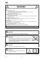
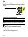
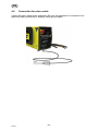
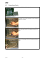
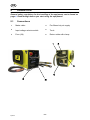
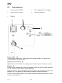
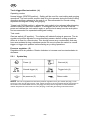
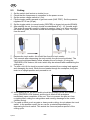
GB Powercut 1600 Instruction manual 0449 551 001 GB 101222 Valid for serial no. 034-xxx-xxxx -2- 1 SAFETY . . . . . . . . . . . . . . . . . . . . . . . . . . . . . . . . . . . . . . . . . . . . . . . . . . . . . . . . . . . 2 INTRODUCTION . . . . . . . . . . . . . . . . . . . . . . . . . . . . . . . . . . . . . . . . . . . . . . . . . . . 2.1 4 6 Equipment . . . . . . . . . . . . . . . . . . . . . . . . . . . . . . . . . . . . . . . . . . . . . . . . . . . . . . . . . . . . . . . . 6 3 TECHNICAL DATA . . . . . . . . . . . . . . . . . . . . . . . . . . . . . . . . . . . . . . . . . . . . . . . . . 4 INSTALLATION . . . . . . . . . . . . . . . . . . . . . . . . . . . . . . . . . . . . . . . . . . . . . . . . . . . . 6 7 4.1 4.2 4.3 4.4 4.5 Delivery check and location . . . . . . . . . . . . . . . . . . . . . . . . . . . . . . . . . . . . . . . . . . . . . . . . . Mains power supply . . . . . . . . . . . . . . . . . . . . . . . . . . . . . . . . . . . . . . . . . . . . . . . . . . . . . . . . Input air connection . . . . . . . . . . . . . . . . . . . . . . . . . . . . . . . . . . . . . . . . . . . . . . . . . . . . . . . . Connection for return cable . . . . . . . . . . . . . . . . . . . . . . . . . . . . . . . . . . . . . . . . . . . . . . . . . Connection of torch . . . . . . . . . . . . . . . . . . . . . . . . . . . . . . . . . . . . . . . . . . . . . . . . . . . . . . . . 8 9 9 10 11 5 OPERATION . . . . . . . . . . . . . . . . . . . . . . . . . . . . . . . . . . . . . . . . . . . . . . . . . . . . . . . 12 5.1 Connections . . . . . . . . . . . . . . . . . . . . . . . . . . . . . . . . . . . . . . . . . . . . . . . . . . . . . . . . . . . . . . 5.2 Control devices . . . . . . . . . . . . . . . . . . . . . . . . . . . . . . . . . . . . . . . . . . . . . . . . . . . . . . . . . . . 5.2.1 Symbol key . . . . . . . . . . . . . . . . . . . . . . . . . . . . . . . . . . . . . . . . . . . . . . . . . . . . . . . . . . 5.3 Cutting . . . . . . . . . . . . . . . . . . . . . . . . . . . . . . . . . . . . . . . . . . . . . . . . . . . . . . . . . . . . . . . . . . . 12 13 14 15 6 MAINTENANCE . . . . . . . . . . . . . . . . . . . . . . . . . . . . . . . . . . . . . . . . . . . . . . . . . . . . 16 6.1 Inspection and cleaning . . . . . . . . . . . . . . . . . . . . . . . . . . . . . . . . . . . . . . . . . . . . . . . . . . . . 16 7 FAULT TRACING . . . . . . . . . . . . . . . . . . . . . . . . . . . . . . . . . . . . . . . . . . . . . . . . . . 17 7.1 Fault codes . . . . . . . . . . . . . . . . . . . . . . . . . . . . . . . . . . . . . . . . . . . . . . . . . . . . . . . . . . . . . . . 18 8 ORDERING SPARE PARTS . . . . . . . . . . . . . . . . . . . . . . . . . . . . . . . . . . . . . . . . . DIAGRAM . . . . . . . . . . . . . . . . . . . . . . . . . . . . . . . . . . . . . . . . . . . . . . . . . . . . . . . . . . . . ORDERING NUMBER . . . . . . . . . . . . . . . . . . . . . . . . . . . . . . . . . . . . . . . . . . . . . . . . . ACCESSORIES . . . . . . . . . . . . . . . . . . . . . . . . . . . . . . . . . . . . . . . . . . . . . . . . . . . . . . . 19 20 22 23 Rights reserved to alter specifications without notice. TOCe -3- GB 1 SAFETY Users of ESAB equipment have the ultimate responsibility for ensuring that anyone who works on or near the equipment observes all the relevant safety precautions. Safety precautions must meet the requirements that apply to this type of equipment. The following recommendations should be ob served in addition to the standard regulations that apply to the workplace. All work must be carried out by trained personnel well-acquainted with the operation of the equip ment. Incorrect operation of the equipment may lead to hazardous situations which can result in in jury to the operator and damage to the equipment. 1. Anyone who uses the equipment must be familiar with: S its operation S location of emergency stops S its function S relevant safety precautions S welding and cutting 2. The operator must ensure that: S no unauthorized person is stationed within the working area of the equipment when it is started up. S no-one is unprotected when the arc is struck 3. The workplace must: S be suitable for the purpose S be free from drafts 4. Personal safety equipment S Always wear recommended personal safety equipment, such as safety glasses, flame-proof clothing, safety gloves. Note! Do not use safety gloves when replacing wire. S Do not wear loose-fitting items, such as scarves, bracelets, rings, etc., which could become trapped or cause burns. 5. General precautions S Make sure the return cable is connected securely. S Work on high voltage equipment may only be carried out by a qualified electrician. S Appropriate fire extinquishing equipment must be clearly marked and close at hand. S Lubrication and maintenance must not be carried out on the equipment during operation. -4bp16ea GB WARNING Arc welding and cutting can be injurious to yourself and others. Take precausions when welding and cutting. Ask for your employer's safety practices which should be based on manufacturers' hazard data. ELECTRIC SHOCK - Can kill S Install and earth the unit in accordance with applicable standards. S Do not touch live electrical parts or electrodes with bare skin, wet gloves or wet clothing. S Insulate yourself from earth and the workpiece. S Ensure your working stance is safe. FUMES AND GASES - Can be dangerous to health S Keep your head out of the fumes. S Use ventilation, extraction at the arc, or both, to take fumes and gases away from your breathing zone and the general area. ARC RAYS - Can injure eyes and burn skin. S Protect your eyes and body. Use the correct welding screen and filter lens and wear protective clothing. S Protect bystanders with suitable screens or curtains. FIRE HAZARD S Sparks (spatter) can cause fire. Make sure therefore that there are no inflammable materials nearby. NOISE - Excessive noise can damage hearing S Protect your ears. Use earmuffs or other hearing protection. S Warn bystanders of the risk. MALFUNCTION - Call for expert assistance in the event of malfunction. Read and understand the instruction manual before installing or operating. PROTECT YOURSELF AND OTHERS! WARNING Do not use the power source for thawing frozen pipes. CAUTION Class A equipment is not intended for use in residential locations where the electrical power is provided by the public low-voltage supply system. There may be potential difficulties in ensuring electromagnetic compatibility of class A equipment in those locations, due to conducted as well as radiated disturbances. CAUTION This product is solely intended for plasma cutting. CAUTION Read and understand the instruction manual before installing or operating. -5bp16ea GB Dispose of electronic equipment at the recycling facility! In observance of European Directive 2002/96/EC on Waste Electrical and Electronic Equipment and its implementation in accordance with national law, electrical and/or electronic equipment that has reached the end of its life must be disposed of at a recycling facility. As the person responsible for the equipment, it is your responsibility to obtain information on approved collection stations. For further information contact the nearest ESAB dealer. ESAB can provide you with all necessary cutting protection and accessories. 2 INTRODUCTION The plasma power source Powercut 1600 and the plasma cutting torch PT-38 are a complete and safe plasma cutting system for manual cutting and gouging. It delivers cutting power for severing materials up to 45 mm thickness. ESAB's accessories for the product can be found on page 23. 2.1 Equipment The power source is supplied with: S mains cable, 3 m S instruction manual S return cable incl clamp S plasma cutting torch, 7.5 m, supplied according to the denomination on page 22. 3 TECHNICAL DATA Powercut 1600 Mains voltage 3 400 V $10 % 50/60 Hz Mains supply Ssc min. 4.0 MVA Zmax. 0.04 Setting range 20 – 90 A Permitted load 60 % duty cycle 100 % duty cycle 90 A / 115 V 70 A / 115 V Efficiency at maximum current 89 % Open-circuit voltage U0 280 V Operating temperature –10 to 40 °C Transportation temperature –20 to 55 °C Sound pressure at no load < 70 db (A) Dimensions, l x w x h 706 x 322 x 379 mm Weight 41 kg Insulation class transformer H Enclosure class IP 23 -6bp16ea GB Mains supply, Ssc min Minimum short circuit power on the network in accordance with IEC 61000-3-12 Mains supply, Zmax Maximum permissible line impedance of the network in accordance with IEC 61000-3-11. Duty cycle The duty cycle refers to the time as a percentage of a ten-minute period that you can weld or cut at a certain load without overloading. The duty cycle is valid for 40° C. Enclosure class The IP code indicates the enclosure class, i. e. the degree of protection against penetration by solid objects or water. Equipment marked IP23 is designed for indoor and outdoor use. 4 INSTALLATION The installation must be executed by a professional. Correct installation is very important for trouble-free operation and good cutting results. Carefully read and follow each step in this chapter. WARNING ELECTRIC SHOCKS CAN KILL Take precautionary measures against electric shocks. Ensure that all power supplies are disconnected – switch off the switch at the wall socket and pull out the equipment's power cable from the socket before making any electrical connections in the power source. WARNING It is very important that the chassis is connected to the approved electric protective earth, to prevent electric shocks and electrical accidents. Ensure that protective earth is not connected to any phase conductors by mistake. WARNING Poor connections or failure to connect the return cable to the workpiece can result in fatal electric shock. WARNING Air filter devices may not be used – installation or mounting of any form of air filter device prevents the cold air flow and causes a risk of overheating. The warranty is invalidated if any type of air filter is used. -7bp16ea GB WARNING Do NOT start the equipment with the cover removed. Do NOT connect the equipment under tension or when you are holding it or carrying it. Do NOT touch any of the torch's parts when the power supply is on. CAUTION This product is intended for industrial use. In a domestic environment this product may cause radio interference. It is the user's responsibility to take adequate precautions. CAUTION Place the power source at least 3 metres from the cutting area as sparks and slag spray can damage the power source 4.1 Delivery check and location 1. Remove the packaging. Inspect the equipment for damage that was not immediately apparent upon reception of the delivery. Immediately report any damage to the delivery company. 2. Check for any loose parts in the packaging. Check that the air ducts in the cover's rear panel are not blocked with packaging material that can prevent the air flow through the power source. The power source has a lifting eyelet and can be lifted easily. Check that the lifting equipment that is to be used can withstand the weight of the power source. The weight is stated in the table TECHNICAL DATA, see chapter 3. WARNING The product must be lifted as follows: 3. Position the power source so that its cooling air inlets and outlets are not obstructed. Minimum permitted distance to wall or other obstruction is 30 cm. 4. An air source that gives clean and dry air, at least 236 l/m at 6.2 bar (90 psig), is required for cutting. The cutting air pressure must not exceed 10.3 bar (150 psig), which is the maximum inlet pressure for the filter regulator that is included in the delivery. -8bp16ea GB 4.2 Mains power supply Make sure that the power source is connected to the correct supply voltage and that it is protected by the correct fuse rating. The outlet shall have a protectiv earth connection. Rating plate with supply connection data Recommended fuse sizes and minimum cable area Powercut 1600 50 Hz Mains voltage Mains cable area mm 400 V 2 4G6 Phase current I1eff 20 A Fuse, anti-surge 25 A NOTE! The mains cable areas and fuse sizes as shown above are in accordance with Swedish regulations. Use the power source in accordance with the relevant national regulations. WARNING Make sure the power source is switched off before removing the fuse. 4.3 Input air connection Connect your air supply to the inlet connection of the filter. -9bp16ea GB 4.4 Connection for return cable Clamp the return cable to the workpiece. Be sure the workpiece is connected to an approved earth ground with a properly sized ground cable. - 10 bp16ea GB 4.5 Connection of torch Open the lid on the front panel. Connect the torch cable receptacle to the panel receptacle. Check the orientation of the sockets to ensure a correct fit. Connect the air hose to the quick-connect fitting. Place the strain relief in the square cutout in the front. Connect the mains cable into the plug on the front and turn it clockwise until it is secured. Put the lid back. - 11 bp16ea GB 5 OPERATION General safety regulations for the handling of the equipment can be found on page 4. Read through before you start using the equipment! 5.1 Connections 1 Mains cable 4 Pre-filtered dry air supply 2 Input voltage selector switch 5 Torch 3 Fuse (2A) 6 Return cable with clamp - 12 bp16ea GB 5.2 Control devices 1 Power switch ON/OFF 4 Torch trigger/ Gas test trigger 2 Output current control 5 Pressure regulator 3 Display Power switch - (1) Turn the knob clockwise to “ON” position for normal operation. Turn the knob counterclockwise to switch “OFF”. Output current control - (2) Adjustable from 20 to 90 A. For settings see cut data charts in the torch manual. Display - (3) Shows current settings during normal operation. When the unit is initially switched on, the software version will be briefly displayed. When the unit is in the “GAS TEST” mode, the display will indicate the air pressure setting in bar. The setting can be switched to psi by a service technician. Should a fault condition exist in the normal operation, the display will show a code number, see chapter 7.1. - 13 bp16ea GB Torch trigger/Gas test switch - (4) Operating modes: Normal trigger (CENTER position) - Setting will be used for most cutting and gouging operations. The torch switch must be held in by the operator during the entire cutting operation and then released at the end of cut. Recommended for normal cutting, expanded metal/grate cutting and gouging. Trigger lock (DOWN position) - allows the torch switch to be released after triggering and the cutting arc has been initiated. To extinguish the arc at the end of the cut, press and release the torch switch again or pull the torch away from the work piece. Not recommended for expanded metal/grate cutting. Test mode: Gas test switch (UP position) - The display will indicate flowing air pressure. The air regulator should be adjusted to recommended pressure before cutting operations. Allow air to flow for a few minutes. This should remove any condensation that may have accumulated during a shutdown period. Be sure to place the switch in normal trigger or trigger lock position before starting any cutting operations. Pressure regulator - (5) Regulates torch air pressure. Rotate clockwise to increase and counterclockwise to decrease. 5.2.1 Symbol key Power (1) Gas test (4) Normal trigger (4) Trigger lock (4) Air pressure (5) Return cable NOTE! The unit is supplied from the factory with the regulator set to give 5.5 bar (80 psig) to the torch from a 6.5 bar (95 psig) supply. If the supply pressure to the unit exceeds 6.5 bar (95 psig)up to the maximum recommended 10.3 bar (150 psig), turn the pressure regulator counterclockwise to reduce the pressure to the torch to 5.5 bar (80 psig). Follow the gas testing instructions above. - 14 bp16ea GB 5.3 Cutting 1. 2. 3. 4. Set the switch (wall socket or similar) to on. Check that the compressor is connected to the power source. Set the mains voltage switch to I (On). Flip the toggle switch upwards to gas test mode (GAS TEST). Set the pressure regulator to 5.5 bar (80 psi). 5. Set the toggle switch to normal mode (CENTER) or trigger lock mode (DOWN). 6. After starting the cut, the torch should be maintained at a 5 - 15 forward angle. This angle is especially useful in helping to create a “drop” cut. When not using the stand-off guide, the nozzle should be held approximately 3.2 mm - 6.4 mm from the work. 7. Depress the torch switch. Air should flow from the torch nozzle. 8. Two seconds after depressing the torch switch, the pilot arc should start. The main arc should immediately follow, allowing the cut to begin. (If using the TRIGGER LOCK feature, the torch switch may be released after establishing the cutting arc.) 9. To start a cut, tilt the torch to prevent molten material from coming back against and damaging the torch. When the arc breaks through the workpiece, bring the torch to an upright position and proceed to cut. 10. When ending a cut, the torch switch should be released (press and release if using TRIGGER LOCK feature) and the torch lifted off the workpiece immediately upon completion of the cut. This is to prevent the pilot arc from re-igniting after cutting arc extinguishes and causing damange to the nozzle (double arcing). 11. For rapid re-starts, such as grate or heavy mesh cutting, do not release the torch switch. In the postflow mode, the arc can be re-started immediately by depressing the torch switch. This avoids the 2-second preflow portion of the cutting cycle. - 15 bp16ea GB 6 MAINTENANCE Regular maintenance is important for safe, reliable operation. Only those persons who have appropriate electrical knowledge (authorized personnel) may remove the safety plates. WARNING Ensure that the mains voltage supply to the machine has been disconnected externally. Switch off the switch at the wall socket before inspecting or working in the power source. WARNING Water or oil can collect in the compressed air lines. Always direct the first stream of air away from the equipment, to prevent damage. CAUTION All guarantee undertakings from the supplier cease to apply if the customer himself attempts any work in the product during the guarantee period in order to rectify any faults. If the equipment does not work correctly, stop work immediately and determine the cause of the problem. Maintenance work may only be carried out by persons with the applicable knowledge. Electrical work may only be carried out by authorised electricians. Never allow persons other than those with the applicable knowledge to check, clean or repair the equipment. Only use recommended spare parts. 6.1 Inspection and cleaning The following points on the power source should be checked and/or cleaned regularly. 1. Check the return cable connection to the work piece. 2. Check that the protective earth from the work piece is securely connected to the power source chassis earth. 3. Check the torch heat shield. Replace it if it is damaged. 4. Check the electrode and the nozzle for wear daily. Remove any splash, replace the electrode and nozzle as necessary. If the electrode has a pit which is more than 1.5 mm deep at its center, it must be replaced. If the electrode is used beyond this recommended wear limit, damage to the torch and power source may occur. Nozzle life is also greatly reduced when using the electrode below the recommended limit. 5. Check that the cables or hoses are not damaged or bent. 6. Check that all plugs and connections and ground terminals are firmly connected. 7. Ensure that all incoming power supplies are disconnected. Use goggles and face mask and blow clean the power source internally using dry compressed air at low pressure . 8. Regularly drain any water from the filter below the air regulators. - 16 bp16ea GB 7 FAULT TRACING WARNING ELECTRIC SHOCKS CAN KILL Ensure that the mains voltage supply to the machine has been disconnected externally. Switch off the switch at the mains socket before inspecting or working in the power source. WARNING Plasma cutting equipment uses extremely high voltages that can cause severe injury or even death. Observe extreme caution when working with the covers removed. Try these recommended checks and inspections before sending for an authorized service technician. Type of fault No arc. Corrective action S S S The current is interrupted during cutting. S S Check that the mains power supply switch is turned on. Check that the current supply and return cables are correctly connected. Check that the correct current value is set. Check whether the thermal overload trips have operated. Check the mains power supply fuses. The thermal cut-out trips frequently. S Make sure that you are not exceeding the rated data for the power source (i.e. that the unit is not being overloaded). Poor cutting performance. S Check that the current supply and return cables are correctly connected. Check that the correct current value is set. Check that the correct electrode is being used. Check the mains power supply fuses. S S S If you cannot locate the problem switch off the incoming power supply, open the unit and check all components and conductors visually. Look for swollen or leaking condensers and other signs of damage or discolouration. - 17 bp16ea GB 7.1 Fault codes Should a fault condition exist in normal operation, the display will show a code number. All fault signals will remain on for a minimum of 10 seconds. If the fault is cleared, all will reset automatically except for over-current. To clear over-current, the power must be shut off for 5 seconds and then turned back on. Code Problem Cause Solution 1 Mains voltage, idle +/– 15 % Incoming mains voltage may have fallen below or risen above the set nominal value. Check the mains voltage. 2 Mains voltage, cutting +/– 20 % Incoming mains voltage may have fallen below or risen above the set nominal value during ongoing cutting. Check the mains voltage. 3 Operating pre-tensioning, +/– The operating circuit transformer does not supply 15 V pre-tensioning the correct voltage to the distribution operating circuits. Check the transformer and control board. 4 Thermal switches Thermal switches off – equipment overheated. Let the equipment cool. Check that the ventilation is adequate. 5 Pressure The air pressure is outside the permitted interval., min 5.1 bar and max 6.5 bar. Check the supply compressed air and pressure setting. 6 The arc does not strike. Arc transfer could not occur. Check the ground lead. 7 Pilot arc time limit (approx 5 seconds) exceeded. The cutting process did not begin with the 5 second limit. Start within 5 seconds: 8 Torch fault The electrode touches the nozzle (cannot separate). Check/replace consumables. 10 Reconnection problem. The problem primarily occurs if the hall sensor is not connected. Check the cable connection between the current sensor board and the control board. Check the torch for a short circuit between the nozzle and the work piece. Remove any scrap from the front section of the torch. 11 Over current on the primary side. Converter fault. Send the unit to the authorised service workshop for repair. 12 Phase drop, switch off, on the primary side (mains supply) Exceeded single phase duty cycle rating Check the mains power supply fuses. 13 Open circuit voltage fault Neither voltage nor current could be detected at automatic Parts In Place (PIP) check of consumables. Send the unit to the authorised service workshop for repair. 14 Overtemperature in the apparatus sheath. The temperature is higher than the permitted operational limit. Check the ventilation around the unit. Check the cooling air gaps and ensure that any obstacles are removed from there. - 18 bp16ea GB Code Problem Cause Solution 15 Bus charging fault Under voltage on the primary bus. Check the bus charger. 19 Torch trigger early engagement Torch trigger depressed at power up. Check the trigger. 20 No return at PIP (Parts In Place) check of consum ables. The piston was not withdrawn when air was released. Check/clean consumables. Check the compressed air supply. 21 No unbroken current path at PIP (Parts In Place) check of consumables. The piston did not fall back when the air supply was removed. Check/clean consumables. 8 ORDERING SPARE PARTS Repair and electrical work should be performed by an authorized ESAB serviceman. Use only ESAB original spare and wear parts. Powercut 1600 is designed and tested in accordance with the international and Euro pean standards 60974-1 and 60974-10. It is the obligation of the service unit which has carried out the service or repair work to make sure that the product still conforms to the said standard. Always provide the serial number of the unit on which the parts will be used. The serialnumber is stamped on the units measuring plate. Spare parts may be ordered through your nearest ESAB dealer, see the last page of this publication. - 19 bp16ea Diagram - 20 bp16e Edition 101222 - 21 bp16e Edition 101222 Powercut 1600 Ordering number Ordering no. Denomination Type Notes 0558 007 235 Power source for plasma cutting and torch Powercut 1600 + PT38 400 V 0558 007 234 Power source for plasma cutting Powercut 1600 400 V 0558 006 786 Torch 0558 008 016 Service manual PT38 Powercut 1600 7.5 m - 22 bp16o Edition 101222 Powercut 1600 Accessories Trolley . . . . . . . . . . . . . . . . . . . . . . . . . . . . . . . . . . 0558 007 898 Gas flow measuring kit . . . . . . . . . . . . . . . . . . . 0558 000 739 Water separator . . . . . . . . . . . . . . . . . . . . . . . . . . 0558 007 897 PT38 torch, 15.2 m . . . . . . . . . . . . . . . . . . . . . . . 0558 006 787 - 23 bp16a Edition 101222 ESAB subsidiaries and representative offices Europe AUSTRIA ESAB Ges.m.b.H Vienna-Liesing Tel: +43 1 888 25 11 Fax: +43 1 888 25 11 85 BELGIUM S.A. ESAB N.V. Brussels Tel: +32 2 745 11 00 Fax: +32 2 745 11 28 NORWAY AS ESAB Larvik Tel: +47 33 12 10 00 Fax: +47 33 11 52 03 POLAND ESAB Sp.zo.o. Katowice Tel: +48 32 351 11 00 Fax: +48 32 351 11 20 BULGARIA ESAB Kft Representative Office Sofia Tel/Fax: +359 2 974 42 88 PORTUGAL ESAB Lda Lisbon Tel: +351 8 310 960 Fax: +351 1 859 1277 THE CZECH REPUBLIC ESAB VAMBERK s.r.o. Vamberk Tel: +420 2 819 40 885 Fax: +420 2 819 40 120 ROMANIA ESAB Romania Trading SRL Bucharest Tel: +40 316 900 600 Fax: +40 316 900 601 DENMARK Aktieselskabet ESAB Herlev Tel: +45 36 30 01 11 Fax: +45 36 30 40 03 RUSSIA LLC ESAB Moscow Tel: +7 (495) 663 20 08 Fax: +7 (495) 663 20 09 FINLAND ESAB Oy Helsinki Tel: +358 9 547 761 Fax: +358 9 547 77 71 SLOVAKIA ESAB Slovakia s.r.o. Bratislava Tel: +421 7 44 88 24 26 Fax: +421 7 44 88 87 41 FRANCE ESAB France S.A. Cergy Pontoise Tel: +33 1 30 75 55 00 Fax: +33 1 30 75 55 24 SPAIN ESAB Ibérica S.A. Alcalá de Henares (MADRID) Tel: +34 91 878 3600 Fax: +34 91 802 3461 GERMANY ESAB GmbH Solingen Tel: +49 212 298 0 Fax: +49 212 298 218 SWEDEN ESAB Sverige AB Gothenburg Tel: +46 31 50 95 00 Fax: +46 31 50 92 22 GREAT BRITAIN ESAB Group (UK) Ltd Waltham Cross Tel: +44 1992 76 85 15 Fax: +44 1992 71 58 03 ESAB international AB Gothenburg Tel: +46 31 50 90 00 Fax: +46 31 50 93 60 ESAB Automation Ltd Andover Tel: +44 1264 33 22 33 Fax: +44 1264 33 20 74 SWITZERLAND ESAB AG Dietikon Tel: +41 1 741 25 25 Fax: +41 1 740 30 55 HUNGARY ESAB Kft Budapest Tel: +36 1 20 44 182 Fax: +36 1 20 44 186 UKRAINE ESAB Ukraine LLC Kiev Tel: +38 (044) 501 23 24 Fax: +38 (044) 575 21 88 ITALY ESAB Saldatura S.p.A. Mesero (Mi) Tel: +39 02 97 96 81 Fax: +39 02 97 28 91 81 North and South America ARGENTINA CONARCO Buenos Aires Tel: +54 11 4 753 4039 Fax: +54 11 4 753 6313 BRAZIL ESAB S.A. Contagem-MG Tel: +55 31 2191 4333 Fax: +55 31 2191 4440 CANADA ESAB Group Canada Inc. Missisauga, Ontario Tel: +1 905 670 02 20 Fax: +1 905 670 48 79 MEXICO ESAB Mexico S.A. Monterrey Tel: +52 8 350 5959 Fax: +52 8 350 7554 USA ESAB Welding & Cutting Products Florence, SC Tel: +1 843 669 44 11 Fax: +1 843 664 57 48 Asia/Pacific SOUTH KOREA ESAB SeAH Corporation Kyungnam Tel: +82 55 269 8170 Fax: +82 55 289 8864 UNITED ARAB EMIRATES ESAB Middle East FZE Dubai Tel: +971 4 887 21 11 Fax: +971 4 887 22 63 Africa EGYPT ESAB Egypt Dokki-Cairo Tel: +20 2 390 96 69 Fax: +20 2 393 32 13 SOUTH AFRICA ESAB Africa Welding & Cutting Ltd Durbanvill 7570 - Cape Town Tel: +27 (0)21 975 8924 Distributors For addresses and phone numbers to our distributors in other countries, please visit our home page www.esab.com CHINA Shanghai ESAB A/P Shanghai Tel: +86 21 2326 3000 Fax: +86 21 6566 6622 INDIA ESAB India Ltd Calcutta Tel: +91 33 478 45 17 Fax: +91 33 468 18 80 INDONESIA P.T. ESABindo Pratama Jakarta Tel: +62 21 460 0188 Fax: +62 21 461 2929 JAPAN ESAB Japan Tokyo Tel: +81 45 670 7073 Fax: +81 45 670 7001 MALAYSIA ESAB (Malaysia) Snd Bhd USJ Tel: +603 8023 7835 Fax: +603 8023 0225 SINGAPORE ESAB Asia/Pacific Pte Ltd Singapore Tel: +65 6861 43 22 Fax: +65 6861 31 95 THE NETHERLANDS ESAB Nederland B.V. Amersfoort Tel: +31 33 422 35 55 Fax: +31 33 422 35 44 ESAB AB SE-695 81 LAXÅ SWEDEN Phone +46 584 81 000 www.esab.com 101217